WO2017163976A1 - 転がり軸受 - Google Patents
転がり軸受 Download PDFInfo
- Publication number
- WO2017163976A1 WO2017163976A1 PCT/JP2017/009961 JP2017009961W WO2017163976A1 WO 2017163976 A1 WO2017163976 A1 WO 2017163976A1 JP 2017009961 W JP2017009961 W JP 2017009961W WO 2017163976 A1 WO2017163976 A1 WO 2017163976A1
- Authority
- WO
- WIPO (PCT)
- Prior art keywords
- rolling
- raceway surface
- inner ring
- bearing
- outer ring
- Prior art date
- Legal status (The legal status is an assumption and is not a legal conclusion. Google has not performed a legal analysis and makes no representation as to the accuracy of the status listed.)
- Ceased
Links
Images



Classifications
-
- F—MECHANICAL ENGINEERING; LIGHTING; HEATING; WEAPONS; BLASTING
- F16—ENGINEERING ELEMENTS AND UNITS; GENERAL MEASURES FOR PRODUCING AND MAINTAINING EFFECTIVE FUNCTIONING OF MACHINES OR INSTALLATIONS; THERMAL INSULATION IN GENERAL
- F16C—SHAFTS; FLEXIBLE SHAFTS; ELEMENTS OR CRANKSHAFT MECHANISMS; ROTARY BODIES OTHER THAN GEARING ELEMENTS; BEARINGS
- F16C19/00—Bearings with rolling contact, for exclusively rotary movement
- F16C19/02—Bearings with rolling contact, for exclusively rotary movement with bearing balls essentially of the same size in one or more circular rows
- F16C19/14—Bearings with rolling contact, for exclusively rotary movement with bearing balls essentially of the same size in one or more circular rows for both radial and axial load
- F16C19/16—Bearings with rolling contact, for exclusively rotary movement with bearing balls essentially of the same size in one or more circular rows for both radial and axial load with a single row of balls
-
- F—MECHANICAL ENGINEERING; LIGHTING; HEATING; WEAPONS; BLASTING
- F16—ENGINEERING ELEMENTS AND UNITS; GENERAL MEASURES FOR PRODUCING AND MAINTAINING EFFECTIVE FUNCTIONING OF MACHINES OR INSTALLATIONS; THERMAL INSULATION IN GENERAL
- F16C—SHAFTS; FLEXIBLE SHAFTS; ELEMENTS OR CRANKSHAFT MECHANISMS; ROTARY BODIES OTHER THAN GEARING ELEMENTS; BEARINGS
- F16C33/00—Parts of bearings; Special methods for making bearings or parts thereof
- F16C33/30—Parts of ball or roller bearings
- F16C33/38—Ball cages
- F16C33/44—Selection of substances
-
- F—MECHANICAL ENGINEERING; LIGHTING; HEATING; WEAPONS; BLASTING
- F16—ENGINEERING ELEMENTS AND UNITS; GENERAL MEASURES FOR PRODUCING AND MAINTAINING EFFECTIVE FUNCTIONING OF MACHINES OR INSTALLATIONS; THERMAL INSULATION IN GENERAL
- F16C—SHAFTS; FLEXIBLE SHAFTS; ELEMENTS OR CRANKSHAFT MECHANISMS; ROTARY BODIES OTHER THAN GEARING ELEMENTS; BEARINGS
- F16C33/00—Parts of bearings; Special methods for making bearings or parts thereof
- F16C33/30—Parts of ball or roller bearings
- F16C33/66—Special parts or details in view of lubrication
Definitions
- the present invention relates to a solid lubrication type rolling bearing, and more particularly to a rolling bearing suitably used for an apparatus that performs a swinging motion.
- Rolling bearings equipped with rolling elements, such as balls and rollers, between the raceways formed on the outer peripheral surface of the inner ring and the inner peripheral surface of the outer ring, respectively, and with a cage that keeps the spacing between the rolling elements.
- a suitable one is appropriately employed according to the application and purpose of the bearing.
- a solid lubrication method is often employed (Patent Document 1).
- the solid lubrication type rolling bearing adopts, for example, a configuration in which the lubricant is supplied to the inner / outer ring raceway surface via a rolling element from a cage having a function of supplying the lubricant.
- bearings for antenna support parts used in outer space are required to be operated with high rotational accuracy while being accompanied by oscillating motion under the solid lubrication method, so a preload is applied to increase the rigidity.
- the diameter of the rolling element should be increased as much as possible for the purpose of reducing the contact surface pressure between the rolling element and the raceway surface and improving the load capacity of the bearing. Is desirable.
- the rolling element pitch circle If the rolling element diameter (dw) is too large with respect to the diameter (dp), the solid lubricant is not properly transferred to the inner and outer ring raceway surfaces, resulting in poor lubrication.
- the solid lubricant is passed from the cage 7 through the rolling elements 6 to the track surface 4 of the inner ring 2 and the track of the outer ring 3.
- the rolling element 6 needs to autorotate at least 180 degrees (1/2 rotation) or more.
- the rolling element diameter (dw) is too large with respect to the rolling element pitch circle diameter (dp)
- the rolling element cannot rotate 180 ° (1/2 rotation) or more.
- the solid lubricant cannot be transferred from the cage 7 to the raceway surface 4 of the inner ring 2 and the raceway surface 5 of the outer ring 3 via the rolling elements 6.
- the present invention provides a rolling bearing that performs a swinging motion at a swinging angle ⁇ so that the solid lubricant is appropriately transferred from the cage to the raceway surface of the inner ring and the raceway surface of the outer ring through the rolling elements.
- a rolling bearing that performs a swinging motion at a swinging angle ⁇ so that the solid lubricant is appropriately transferred from the cage to the raceway surface of the inner ring and the raceway surface of the outer ring through the rolling elements.
- the present invention provides a bearing specification for transferring a solid lubricant from a cage to a raceway surface of an inner ring and a raceway surface of an outer ring via a rolling element.
- the rolling element diameter (dw) is the rolling element diameter (dw).
- Equation 1 the relationship between the rotation number n a [rpm] of the rolling element and the inner ring rotation number n i [rpm] is expressed by Equation 1.
- dp rolling element pitch circle diameter [mm]
- dw rolling element diameter [mm]
- ⁇ inner ring rocking angle [°]
- ⁇ contact angle [°].
- n 1
- the conditions for the rolling element to rotate 180 ° (1/2 rotation) or more by one swing are as follows from equations (1) and (2): .
- dp / dw required to transfer the solid lubricant from the cage to the raceway surface of the inner ring and the raceway surface of the outer ring based on the above formula (5) is obtained. it can.
- FIG. 4B is a side view showing the rotation motion of the rolling element in the rolling bearing having a dp / dw smaller than that in FIG. 4A.
- 6 is a graph showing the relationship between the swing angle and dp / dw necessary for transferring the solid lubricant to the inner and outer ring raceway surfaces, the contact surface pressure of the bearing, and the load capacity.
- the rolling bearing according to the present invention is a rolling bearing applied for use in a cryogenic environment such as outer space, and is used for, for example, an artificial satellite.
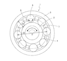
- the rolling bearing 1 includes an inner ring 2 having a raceway surface 4 on an outer peripheral surface, an outer ring 3 having a raceway surface 5 on an inner peripheral surface, a raceway surface 4 of the inner ring 2 and a raceway surface of the outer ring 3.
- 5 is an angular ball bearing comprising a plurality of balls 6 which are a plurality of rolling elements arranged between 5 and a cage 7 which holds the plurality of balls 6 at intervals in the circumferential direction.
- a normal bearing material can be used, for example, martensitic stainless steel can be used.
- the balls 6 may be ceramic balls.
- silicon nitride (Si 3 N 4 ), silicon carbide (SIC), alumina (AI 2 O 3 ), zirconia (ZrO 2 ), sialon and the like can be mentioned.
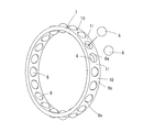
- the cage 7 is made of metal or synthetic resin, and has a plurality of pockets 8 in which balls 6 are accommodated one by one as shown in FIG. Provided at intervals.
- the ball 6 is held in contact with the pocket surface 8 a of each pocket 8 and held in the pocket 8.
- the cage 7 used in the rolling bearing 1 according to the present embodiment is an outer ring guide type cage whose radial position is guided by the inner peripheral surface of the outer ring 3.
- the rolling bearing 1 is lubricated by a solid lubrication method, and a solid lubricant layer made of a solid lubricant or a composite containing the same is provided on the pocket surface 8a of the cage 7.
- a cage in which glass fiber is impregnated with PTFE (polytetrafluoroethylene) and the surface glass fiber is melted to expose the PTFE layer on the surface is also used.
- PTFE polytetrafluoroethylene
- the lubricating coating provided only on the surface of the base is worn, the lubricating performance is lost.
- the lubricating layer is successively displayed even if the surface layer is worn, so that the lubricating performance is maintained.
- the solid lubricant graphite, tungsten disulfide or molybdenum disulfide, and PTFE are used. Further, an appropriate amount of lubricant is supplied from the cage 7 and is supplied to the raceway surfaces 4 and 5 of the inner ring 2 and the outer ring 3 through the balls 6 that are in contact with the pocket surface 8a during operation.
- the angular ball bearing is not limited to an angular ball bearing,
- this invention is not limited to an angular ball bearing,
- the present invention can be applied to various rolling bearings such as roller bearings, tapered roller bearings, and self-aligning roller bearings.
- the solid lubricant is supplied from the cage 7 for each swing angle ⁇ , and the raceway surfaces of the inner ring 2 and the outer ring 3 through the balls 6.
- d p / d w required to transfer to 4, 5 can be obtained.
- FIG. 5 shows the relationship between the swing angle ⁇ , dp / dw required for transferring the solid lubricant to the raceway surfaces 4 and 5 of the inner ring 2 and the outer ring 3, and the contact surface pressure and load capacity of the rolling bearing 1.
- the range in which the rolling element can rotate 180 ° (1/2 rotation) or more is the shaded portion in FIG.
- the rolling element can rotate 180 ° (1/2 rotation) or more, and it can reduce the contact surface pressure of the bearing and increase the load capacity of the bearing. This is when the relationship of the moving body diameter (dw) satisfies the relationship of the equation (6), which is on the parabola of FIG.
- Rolling bearing 2 Inner ring 3: Outer ring 4: Inner ring raceway surface 5: Outer ring raceway surface 6: Ball 7: Cage 8: Cage pocket 8a: Cage pocket surface ⁇ : Swing angle
Landscapes
- Engineering & Computer Science (AREA)
- General Engineering & Computer Science (AREA)
- Mechanical Engineering (AREA)
- Rolling Contact Bearings (AREA)
Abstract
揺動角(θ)で揺動運動を行う転がり軸受(1)において、保持器(7)から固体潤滑剤を転動体(6)を介して内輪(2)の軌道面(4)と外輪(3)の軌道面(5)に適切に移着されるようにして、潤滑不良の発生を防止することを課題とする。保持器(7)から固体潤滑剤を、転動体(6)を介して内輪(2)の軌道面(4)と外輪(3)の軌道面(5)とに移着させるための軸受仕様を、転動体ピッチ円径(dp)と転動体径(dw)との関係式から導いた。
Description
この発明は、固体潤滑方式の転がり軸受に関し、特に、揺動運動を行なう装置に好適に使用される転がり軸受に関する。
内輪の外周面と外輪の内周面とにそれぞれ形成された軌道面の間に、玉やころなどの転動体を組み込み、各転動体相互の間の間隔を保つ保持器を備えた転がり軸受の潤滑方式は、軸受の用途や目的に応じて適宜好適なものが採用されている。例えば、宇宙空間など極低温真空環境での使用を目的とする場合には、固体潤滑方式が採用されることが多い(特許文献1)。
固体潤滑方式の転がり軸受は、例えば、潤滑剤を供給する機能を有した保持器から転動体を介して潤滑剤を内・外輪軌道面に供給する構成を採用する。
ところで、宇宙空間で使用されるアンテナ支持部用等の軸受では、固体潤滑方式のもとで揺動運動を伴いながら高回転精度での運転が求められるため、高剛性化を目的に予圧を負荷した状態で使用される。そのような軸受の場合、固体潤滑剤の破断を防ぐため、転動体と軌道面間での接触面圧の低減や軸受の負荷容量の向上を目的として、可能な限り転動体径を大きくすることが望ましい。
しかしながら、固体潤滑剤を供給する機能を有した保持器から転動体を介して固体潤滑剤を内・外輪軌道面に移着させる潤滑方式で揺動運動をする転がり軸受の場合、転動体ピッチ円径(dp)に対して転動体径(dw)が大きすぎると、内・外輪軌道面への固体潤滑剤の移着が適切に行われず、潤滑不良が発生する。
すなわち、図3に示すように、揺動角θで揺動運動を行う転がり軸受1の場合、保持器7から転動体6を介して固体潤滑剤を内輪2の軌道面4と外輪3の軌道面5に移着させるためには、図4Aに示すように、転動体6は少なくとも180°(1/2回転)以上自転する必要がある。ここで、図4Bに示すように、転動体ピッチ円径(dp)に対して転動体径(dw)が大きすぎると、転動体は180°(1/2回転)以上自転することができず、保持器7から転動体6を介して固体潤滑剤を内輪2の軌道面4と外輪3の軌道面5に移着させることができない。
そこで、この発明は、揺動角θで揺動運動を行う転がり軸受において、保持器から転動体を介して固体潤滑剤を内輪の軌道面と外輪の軌道面に適切に移着されるようにして、潤滑不良の発生を防止することを課題とする。
上記の課題を解決するため、この発明は、保持器から転動体を介して固体潤滑剤を内輪の軌道面と外輪の軌道面に移着させるための軸受仕様を、転動体ピッチ円径(dp)と転動体径(dw)との関係から次のようにして導いたものである。
内輪回転の場合、転動体の自転数na[rpm]と内輪回転数ni[rpm]の関係は式1で表される。

次に、1分間あたりの揺動回数nに対して、内輪回転数は式(2)で表される。

1回の揺動に着目するとn=1となり、1回の揺動で転動体が180°(1/2回転)以上自転するための条件は、式(1)及び(2)から以下となる。
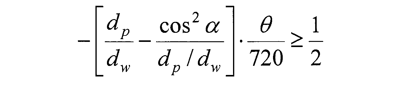
式(3)をdp/dwについて整理すると、式(4)が得られる。

式(4)より、以下の関係式(5)が導かれる。

この発明によれば、上記式(5)に基づき、保持器から転動体を介して固体潤滑剤を内輪の軌道面と外輪の軌道面に移着させるのに必要なdp/dwを求めることができる。
以下、この発明の実施の形態を説明する。
この発明にかかる転がり軸受は、宇宙空間などの極低温環境下での使用に適用した転がり軸受であり、例えば、人工衛星などに用いられる。
この転がり軸受1は、図1に示すように、外周面に軌道面4を有する内輪2と、内周面に軌道面5を有する外輪3と、内輪2の軌道面4と外輪3の軌道面5の間に配置された複数の転動体である玉6と、この複数の玉6を周方向に間隔をおいて保持する保持器7とを備えるアンギュラ玉軸受である。
内輪2、外輪3、及び玉6は、通常の軸受材料を使用することができ、例えば、マルテンサイト系ステンレス鋼を用いることができる。なお、玉6としては、セラミックスボールであってもよい。セラミックスを使用する場合、窒化珪素(Si3N4)、炭化珪素(SIC)、アルミナ(AI2O3)、ジルコニア(ZrO2)、サイアロン等が挙げられる。
保持器7は、金属又は合成樹脂で構成され、図2に示すように、玉6が1つずつ収容される複数のポケット8を有し、図示例では20個のポケット8が円周方向等間隔に設けられる。玉6は、各ポケット8のポケット面8aで接触支持されて、ポケット8内に保持される。本実施形態にかかる転がり軸受1に使用される保持器7は、径方向の位置が外輪3の内周面によって案内される外輪案内方式の保持器となっている。図示を省略しているが、この転がり軸受1の潤滑は、固体潤滑方式であり、保持器7のポケット面8aに固体潤滑剤又はこれを含んだ複合体による固体潤滑層が設けられる。更に、例えば、ガラス繊維にPTFE(ポリテトラフロオロエチレン)を含侵させ、表層のガラス繊維を溶かしてPTFE層を表面に露出させた保持器なども用いられる。母体表面にのみ設けた潤滑被膜は摩耗すると潤滑性能が消失するが、この場合、表層が摩耗しても順次潤滑層が現れるので潤滑性能は維持される。固体潤滑剤としては、グラファイト、二硫化タングステン又は二硫化モリブデン、PTFEが使用される。また、保持器7から適量の潤滑剤が供給され、運転時において、ポケット面8aに接触する玉6を介して内輪2及び外輪3の軌道面4、5に供給される。
なお、以上の実施形態は、アンギュラ玉軸受について述べたが、本発明は、アンギュラ玉軸受に限定されるものではなく、例えば、深溝玉軸受、4点接触玉軸受、自動調心玉軸受、円筒ころ軸受、円錐ころ軸受、自動調心ころ軸受など、種々の転がり軸受に適用可能である。
この発明によれば、上記のように、式(5)を基に、各揺動角θ毎に対して保持器7から固体潤滑剤を、玉6を介して内輪2及び外輪3の軌道面4、5に移着させるのに必要なdp/dwを表1の通り求めることができる。
この発明によれば、上記のように、式(5)を基に、各揺動角θ毎に対して保持器7から固体潤滑剤を、玉6を介して内輪2及び外輪3の軌道面4、5に移着させるのに必要なdp/dwを表1の通り求めることができる。
揺動角θと内輪2及び外輪3の軌道面4、5への固体潤滑剤の移着に必要なdp/dwと、転がり軸受1の接触面圧及び負荷容量の関係は図5の通りであり、転動体が180°(1/2回転)以上自転可能な範囲は図5の斜線部分である。転動体が180°(1/2回転)以上自転可能であり、最も軸受の接触面圧を低減させ、軸受の負荷容量を大きくすることができるのは、転動体ピッチ円径(dp)と転動体径(dw)の関係が図5の放物線上にあたる式(6)の関係を満足する仕様の時である。


以上、図面を参照してこの発明の実施形態を説明したが、この発明は、図示した実施形態のものに限定されない。図示した実施形態に対して、この発明と同一の範囲内において、あるいは均等の範囲内において、種々の修正や変形を加えることが可能である。
1 :転がり軸受
2 :内輪
3 :外輪
4 :内輪軌道面
5 :外輪軌道面
6 :玉
7 :保持器
8 :保持器ポケット
8a :保持器ポケット面
θ :揺動角
2 :内輪
3 :外輪
4 :内輪軌道面
5 :外輪軌道面
6 :玉
7 :保持器
8 :保持器ポケット
8a :保持器ポケット面
θ :揺動角
Claims (4)
- 外周面に軌道面が形成された内輪と、内周面に軌道面が形成された外輪と、前記内輪と外輪の軌道面との間に組み込まれる複数の転動体と、前記内輪及び外輪の間に組み込まれ、転動体を介して固体潤滑剤を内輪の軌道面と外輪の軌道面とに移着させる保持器とを備え、揺動角θで揺動運動を行う転がり軸受において、転動体ピッチ円径(dp)と転動体径(dw)の関係が、次式を満足する軸受仕様であることを特徴とする転がり軸受。

dw:転動体径[mm]
θ:内輪揺動角[°]
α:接触角[°]
- 保持器から供給する固体潤滑剤として、二硫化モリブデン、二硫化タングステン、グラファイト、ポリテトラフルオロエチレンのいずれかを用いた請求項1に記載の転がり軸受。
- 宇宙空間用として使用される前記請求項1又は2に記載の転がり軸受。
- アンギュラ玉軸受である請求項1~3のいずれかに記載の転がり軸受。
Applications Claiming Priority (2)
| Application Number | Priority Date | Filing Date | Title |
|---|---|---|---|
| JP2016057824A JP2017172649A (ja) | 2016-03-23 | 2016-03-23 | 転がり軸受 |
| JP2016-057824 | 2016-03-23 |
Publications (1)
| Publication Number | Publication Date |
|---|---|
| WO2017163976A1 true WO2017163976A1 (ja) | 2017-09-28 |
Family
ID=59899489
Family Applications (1)
| Application Number | Title | Priority Date | Filing Date |
|---|---|---|---|
| PCT/JP2017/009961 Ceased WO2017163976A1 (ja) | 2016-03-23 | 2017-03-13 | 転がり軸受 |
Country Status (2)
| Country | Link |
|---|---|
| JP (1) | JP2017172649A (ja) |
| WO (1) | WO2017163976A1 (ja) |
Cited By (1)
| Publication number | Priority date | Publication date | Assignee | Title |
|---|---|---|---|---|
| JPWO2023002630A1 (ja) * | 2021-07-21 | 2023-01-26 |
Families Citing this family (1)
| Publication number | Priority date | Publication date | Assignee | Title |
|---|---|---|---|---|
| PL233795B1 (pl) * | 2017-11-16 | 2019-11-29 | Zbigniew Kusznierewicz | Lozysko toczne |
Citations (3)
| Publication number | Priority date | Publication date | Assignee | Title |
|---|---|---|---|---|
| JP2009236314A (ja) * | 2008-03-03 | 2009-10-15 | Nsk Ltd | 玉軸受 |
| JP2011226624A (ja) * | 2010-04-23 | 2011-11-10 | Nsk Ltd | 搬送ローラ用転がり軸受 |
| JP2014020530A (ja) * | 2012-07-23 | 2014-02-03 | Nsk Ltd | 転がり軸受 |
-
2016
- 2016-03-23 JP JP2016057824A patent/JP2017172649A/ja active Pending
-
2017
- 2017-03-13 WO PCT/JP2017/009961 patent/WO2017163976A1/ja not_active Ceased
Patent Citations (3)
| Publication number | Priority date | Publication date | Assignee | Title |
|---|---|---|---|---|
| JP2009236314A (ja) * | 2008-03-03 | 2009-10-15 | Nsk Ltd | 玉軸受 |
| JP2011226624A (ja) * | 2010-04-23 | 2011-11-10 | Nsk Ltd | 搬送ローラ用転がり軸受 |
| JP2014020530A (ja) * | 2012-07-23 | 2014-02-03 | Nsk Ltd | 転がり軸受 |
Cited By (4)
| Publication number | Priority date | Publication date | Assignee | Title |
|---|---|---|---|---|
| JPWO2023002630A1 (ja) * | 2021-07-21 | 2023-01-26 | ||
| WO2023002630A1 (ja) * | 2021-07-21 | 2023-01-26 | 株式会社ハーモニック・ドライブ・システムズ | 宇宙用転がり軸受および宇宙用波動歯車装置 |
| JP7520474B2 (ja) | 2021-07-21 | 2024-07-23 | 株式会社ハーモニック・ドライブ・システムズ | 宇宙用転がり軸受および宇宙用波動歯車装置 |
| US12359710B2 (en) | 2021-07-21 | 2025-07-15 | Harmonic Drive Systems Inc. | Space rolling bearing and space strain wave gearing device |
Also Published As
| Publication number | Publication date |
|---|---|
| JP2017172649A (ja) | 2017-09-28 |
Similar Documents
| Publication | Publication Date | Title |
|---|---|---|
| JP2008240796A (ja) | シール付きアンギュラ玉軸受及び主軸装置 | |
| CN1297757C (zh) | 滚动轴承 | |
| WO2017163976A1 (ja) | 転がり軸受 | |
| US20080019623A1 (en) | Rolling bearing and cage for rolling bearing | |
| JP2011112201A (ja) | 玉軸受 | |
| JP2003139146A (ja) | ボールねじ支持用多点接触玉軸受 | |
| JP2000120707A (ja) | 転がり軸受 | |
| JP2009222145A (ja) | 多列転がり軸受 | |
| JPH1182522A (ja) | 磁気軸受装置のタッチダウン軸受 | |
| US20180256290A1 (en) | Ball bearing construction with tilt compensation | |
| JPH1089364A (ja) | 固体潤滑クロスロ−ラ軸受 | |
| JP2017115966A (ja) | 転がり軸受 | |
| JP2018204740A (ja) | 転がり軸受用保持器および転がり軸受 | |
| JP2010196861A (ja) | 転がり軸受 | |
| JP5985684B2 (ja) | スラスト軸受及びその保持器 | |
| JP2017172678A (ja) | 極低温環境用転がり軸受 | |
| JP2016180457A (ja) | 転がり軸受 | |
| CN215293280U (zh) | 轴承装置 | |
| JP2007232092A (ja) | 球面滑り軸受 | |
| JP2010270819A (ja) | 玉軸受 | |
| JP2007285445A (ja) | 固体潤滑転がり軸受 | |
| JP2011112195A (ja) | 玉軸受 | |
| JP2017106560A (ja) | 組合わせ転がり軸受 | |
| JP2004347001A (ja) | 人工衛星姿勢制御フライホイール用組合せ転がり軸受 | |
| JP2016196945A (ja) | 転がり軸受 |
Legal Events
| Date | Code | Title | Description |
|---|---|---|---|
| NENP | Non-entry into the national phase |
Ref country code: DE |
|
| 121 | Ep: the epo has been informed by wipo that ep was designated in this application |
Ref document number: 17770019 Country of ref document: EP Kind code of ref document: A1 |
|
| 122 | Ep: pct application non-entry in european phase |
Ref document number: 17770019 Country of ref document: EP Kind code of ref document: A1 |