WO2017163684A1 - Electric power steering device and method for manufacturing electric power steering device - Google Patents
Electric power steering device and method for manufacturing electric power steering device Download PDFInfo
- Publication number
- WO2017163684A1 WO2017163684A1 PCT/JP2017/005736 JP2017005736W WO2017163684A1 WO 2017163684 A1 WO2017163684 A1 WO 2017163684A1 JP 2017005736 W JP2017005736 W JP 2017005736W WO 2017163684 A1 WO2017163684 A1 WO 2017163684A1
- Authority
- WO
- WIPO (PCT)
- Prior art keywords
- insertion hole
- electric power
- power steering
- bearing
- plug
- Prior art date
Links
- 238000004519 manufacturing process Methods 0.000 title claims description 18
- 238000000034 method Methods 0.000 title claims description 10
- 238000003780 insertion Methods 0.000 claims abstract description 87
- 230000037431 insertion Effects 0.000 claims abstract description 87
- 230000002093 peripheral effect Effects 0.000 claims description 80
- 229910000831 Steel Inorganic materials 0.000 description 4
- XAGFODPZIPBFFR-UHFFFAOYSA-N aluminium Chemical compound [Al] XAGFODPZIPBFFR-UHFFFAOYSA-N 0.000 description 4
- 229910052782 aluminium Inorganic materials 0.000 description 4
- 239000010959 steel Substances 0.000 description 4
- 230000006835 compression Effects 0.000 description 2
- 238000007906 compression Methods 0.000 description 2
- 230000004048 modification Effects 0.000 description 2
- 238000012986 modification Methods 0.000 description 2
- 238000005452 bending Methods 0.000 description 1
- 230000000903 blocking effect Effects 0.000 description 1
- 239000003638 chemical reducing agent Substances 0.000 description 1
- 230000008602 contraction Effects 0.000 description 1
- 238000010586 diagram Methods 0.000 description 1
- 230000000694 effects Effects 0.000 description 1
- 238000005516 engineering process Methods 0.000 description 1
- 239000007788 liquid Substances 0.000 description 1
- 238000003825 pressing Methods 0.000 description 1
- 238000007789 sealing Methods 0.000 description 1
- 238000009751 slip forming Methods 0.000 description 1
- 238000004078 waterproofing Methods 0.000 description 1
Images


Classifications
-
- F—MECHANICAL ENGINEERING; LIGHTING; HEATING; WEAPONS; BLASTING
- F16—ENGINEERING ELEMENTS AND UNITS; GENERAL MEASURES FOR PRODUCING AND MAINTAINING EFFECTIVE FUNCTIONING OF MACHINES OR INSTALLATIONS; THERMAL INSULATION IN GENERAL
- F16C—SHAFTS; FLEXIBLE SHAFTS; ELEMENTS OR CRANKSHAFT MECHANISMS; ROTARY BODIES OTHER THAN GEARING ELEMENTS; BEARINGS
- F16C19/00—Bearings with rolling contact, for exclusively rotary movement
- F16C19/02—Bearings with rolling contact, for exclusively rotary movement with bearing balls essentially of the same size in one or more circular rows
- F16C19/04—Bearings with rolling contact, for exclusively rotary movement with bearing balls essentially of the same size in one or more circular rows for radial load mainly
- F16C19/06—Bearings with rolling contact, for exclusively rotary movement with bearing balls essentially of the same size in one or more circular rows for radial load mainly with a single row or balls
-
- B—PERFORMING OPERATIONS; TRANSPORTING
- B62—LAND VEHICLES FOR TRAVELLING OTHERWISE THAN ON RAILS
- B62D—MOTOR VEHICLES; TRAILERS
- B62D5/00—Power-assisted or power-driven steering
- B62D5/04—Power-assisted or power-driven steering electrical, e.g. using an electric servo-motor connected to, or forming part of, the steering gear
- B62D5/0442—Conversion of rotational into longitudinal movement
- B62D5/0454—Worm gears
-
- B—PERFORMING OPERATIONS; TRANSPORTING
- B62—LAND VEHICLES FOR TRAVELLING OTHERWISE THAN ON RAILS
- B62D—MOTOR VEHICLES; TRAILERS
- B62D3/00—Steering gears
- B62D3/02—Steering gears mechanical
- B62D3/04—Steering gears mechanical of worm type
-
- B—PERFORMING OPERATIONS; TRANSPORTING
- B62—LAND VEHICLES FOR TRAVELLING OTHERWISE THAN ON RAILS
- B62D—MOTOR VEHICLES; TRAILERS
- B62D5/00—Power-assisted or power-driven steering
- B62D5/04—Power-assisted or power-driven steering electrical, e.g. using an electric servo-motor connected to, or forming part of, the steering gear
- B62D5/0403—Power-assisted or power-driven steering electrical, e.g. using an electric servo-motor connected to, or forming part of, the steering gear characterised by constructional features, e.g. common housing for motor and gear box
-
- B—PERFORMING OPERATIONS; TRANSPORTING
- B62—LAND VEHICLES FOR TRAVELLING OTHERWISE THAN ON RAILS
- B62D—MOTOR VEHICLES; TRAILERS
- B62D5/00—Power-assisted or power-driven steering
- B62D5/04—Power-assisted or power-driven steering electrical, e.g. using an electric servo-motor connected to, or forming part of, the steering gear
- B62D5/0409—Electric motor acting on the steering column
-
- F—MECHANICAL ENGINEERING; LIGHTING; HEATING; WEAPONS; BLASTING
- F16—ENGINEERING ELEMENTS AND UNITS; GENERAL MEASURES FOR PRODUCING AND MAINTAINING EFFECTIVE FUNCTIONING OF MACHINES OR INSTALLATIONS; THERMAL INSULATION IN GENERAL
- F16C—SHAFTS; FLEXIBLE SHAFTS; ELEMENTS OR CRANKSHAFT MECHANISMS; ROTARY BODIES OTHER THAN GEARING ELEMENTS; BEARINGS
- F16C35/00—Rigid support of bearing units; Housings, e.g. caps, covers
- F16C35/04—Rigid support of bearing units; Housings, e.g. caps, covers in the case of ball or roller bearings
- F16C35/06—Mounting or dismounting of ball or roller bearings; Fixing them onto shaft or in housing
- F16C35/067—Fixing them in a housing
-
- F—MECHANICAL ENGINEERING; LIGHTING; HEATING; WEAPONS; BLASTING
- F16—ENGINEERING ELEMENTS AND UNITS; GENERAL MEASURES FOR PRODUCING AND MAINTAINING EFFECTIVE FUNCTIONING OF MACHINES OR INSTALLATIONS; THERMAL INSULATION IN GENERAL
- F16C—SHAFTS; FLEXIBLE SHAFTS; ELEMENTS OR CRANKSHAFT MECHANISMS; ROTARY BODIES OTHER THAN GEARING ELEMENTS; BEARINGS
- F16C35/00—Rigid support of bearing units; Housings, e.g. caps, covers
- F16C35/04—Rigid support of bearing units; Housings, e.g. caps, covers in the case of ball or roller bearings
- F16C35/06—Mounting or dismounting of ball or roller bearings; Fixing them onto shaft or in housing
- F16C35/07—Fixing them on the shaft or housing with interposition of an element
- F16C35/077—Fixing them on the shaft or housing with interposition of an element between housing and outer race ring
-
- F—MECHANICAL ENGINEERING; LIGHTING; HEATING; WEAPONS; BLASTING
- F16—ENGINEERING ELEMENTS AND UNITS; GENERAL MEASURES FOR PRODUCING AND MAINTAINING EFFECTIVE FUNCTIONING OF MACHINES OR INSTALLATIONS; THERMAL INSULATION IN GENERAL
- F16H—GEARING
- F16H1/00—Toothed gearings for conveying rotary motion
- F16H1/02—Toothed gearings for conveying rotary motion without gears having orbital motion
- F16H1/04—Toothed gearings for conveying rotary motion without gears having orbital motion involving only two intermeshing members
- F16H1/12—Toothed gearings for conveying rotary motion without gears having orbital motion involving only two intermeshing members with non-parallel axes
- F16H1/16—Toothed gearings for conveying rotary motion without gears having orbital motion involving only two intermeshing members with non-parallel axes comprising worm and worm-wheel
- F16H1/166—Toothed gearings for conveying rotary motion without gears having orbital motion involving only two intermeshing members with non-parallel axes comprising worm and worm-wheel with members rotating around axes on the worm or worm-wheel
-
- F—MECHANICAL ENGINEERING; LIGHTING; HEATING; WEAPONS; BLASTING
- F16—ENGINEERING ELEMENTS AND UNITS; GENERAL MEASURES FOR PRODUCING AND MAINTAINING EFFECTIVE FUNCTIONING OF MACHINES OR INSTALLATIONS; THERMAL INSULATION IN GENERAL
- F16H—GEARING
- F16H55/00—Elements with teeth or friction surfaces for conveying motion; Worms, pulleys or sheaves for gearing mechanisms
- F16H55/02—Toothed members; Worms
- F16H55/22—Toothed members; Worms for transmissions with crossing shafts, especially worms, worm-gears
- F16H55/24—Special devices for taking up backlash
-
- F—MECHANICAL ENGINEERING; LIGHTING; HEATING; WEAPONS; BLASTING
- F16—ENGINEERING ELEMENTS AND UNITS; GENERAL MEASURES FOR PRODUCING AND MAINTAINING EFFECTIVE FUNCTIONING OF MACHINES OR INSTALLATIONS; THERMAL INSULATION IN GENERAL
- F16H—GEARING
- F16H57/00—General details of gearing
- F16H57/02—Gearboxes; Mounting gearing therein
- F16H57/021—Shaft support structures, e.g. partition walls, bearing eyes, casing walls or covers with bearings
-
- F—MECHANICAL ENGINEERING; LIGHTING; HEATING; WEAPONS; BLASTING
- F16—ENGINEERING ELEMENTS AND UNITS; GENERAL MEASURES FOR PRODUCING AND MAINTAINING EFFECTIVE FUNCTIONING OF MACHINES OR INSTALLATIONS; THERMAL INSULATION IN GENERAL
- F16C—SHAFTS; FLEXIBLE SHAFTS; ELEMENTS OR CRANKSHAFT MECHANISMS; ROTARY BODIES OTHER THAN GEARING ELEMENTS; BEARINGS
- F16C2361/00—Apparatus or articles in engineering in general
- F16C2361/61—Toothed gear systems, e.g. support of pinion shafts
-
- F—MECHANICAL ENGINEERING; LIGHTING; HEATING; WEAPONS; BLASTING
- F16—ENGINEERING ELEMENTS AND UNITS; GENERAL MEASURES FOR PRODUCING AND MAINTAINING EFFECTIVE FUNCTIONING OF MACHINES OR INSTALLATIONS; THERMAL INSULATION IN GENERAL
- F16H—GEARING
- F16H57/00—General details of gearing
- F16H57/02—Gearboxes; Mounting gearing therein
- F16H57/021—Shaft support structures, e.g. partition walls, bearing eyes, casing walls or covers with bearings
- F16H2057/0213—Support of worm gear shafts
Definitions
- the present invention relates to an electric power steering apparatus and a method for manufacturing the electric power steering apparatus.
- JP2012-197029A discloses an electric power steering device in which a spring is compressed between the outer peripheral surface of the bearing and the plug by press-fitting the plug into a through hole formed in the gear case. Has been.
- An O-ring is interposed between the outer peripheral surface of the gear case and the head of the plug. The gap between the gear case and the plug is sealed by the O-ring, and the gear case is sealed.
- an O-ring is provided between the plug and the gear case, and the number of parts is large. Further, before the plug is press-fitted into the through hole of the gear case, an O-ring must be assembled to the plug. Therefore, it takes time to manufacture the power steering device.
- An object of the present invention is to make it possible to reduce the number of parts of an electric power steering device while preventing mixing of shavings into a gear case.
- an electric power steering device includes a worm shaft that rotates as the electric motor is driven, a worm shaft that meshes with the worm shaft and transmits the rotational force of the electric motor to a rack shaft that steers the wheel.
- a wheel, a bearing that rotatably supports the worm shaft, a biasing member that biases the worm shaft toward the worm wheel via the bearing, a worm shaft and the bearing are accommodated, and the biasing member can be inserted.
- a gear case having an insertion hole; and a closing member that closes the insertion hole.
- the closing member is disposed in the insertion hole and is in contact with the inner peripheral surface of the insertion hole, and is continuous with the body portion toward the bearing.
- a support portion that supports the biasing member, and the outer peripheral surface of the closing member is formed in a curved shape from the main body portion to the support portion.
- the present invention also provides an urging member for urging the worm shaft toward the worm wheel via a bearing, a case that houses the worm shaft and the bearing, and has an insertion hole through which the urging member can be inserted, A closing member that closes the hole, and the closing member is disposed in the insertion hole and is in contact with the inner peripheral surface of the insertion hole, and is formed continuously from the body portion toward the bearing to support the biasing member.
- a method for manufacturing an electric power steering apparatus includes a step of press-fitting a closing member into an insertion hole in a state where a protruding portion protruding from a bottom portion is supported.
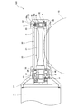
- FIG. 1 is a cross-sectional view showing an electric power steering apparatus according to a first embodiment of the present invention.
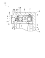
- FIG. 2 is an enlarged cross-sectional view showing the periphery of the closing member in FIG.
- FIG. 3 is an enlarged cross-sectional view corresponding to FIG. 2 showing an electric power steering apparatus according to a modification of the first embodiment.
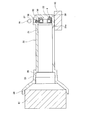
- FIG. 4 is a view for explaining the method for manufacturing the electric power steering apparatus according to the first embodiment.
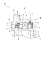
- FIG. 5 is a cross-sectional view showing an electric power steering apparatus according to the second embodiment of the present invention.
- 6 is an enlarged cross-sectional view showing the periphery of the closing member in FIG.
- FIG. 7 is a diagram for explaining a method of manufacturing the electric power steering apparatus according to the second embodiment.
- an electric power steering apparatus 100 according to a first embodiment of the present invention will be described with reference to FIGS. 1 to 4.
- the electric power steering device 100 is mounted on a vehicle and assists the steering force applied by the driver to the steering wheel.
- the electric power steering apparatus 100 includes a worm shaft 20 connected to the output shaft of the electric motor 1 and a worm wheel 10 that meshes with the worm shaft 20.
- the worm shaft 20 rotates as the electric motor 1 is driven.
- the worm wheel 10 rotates as the worm shaft 20 rotates, and transmits the rotational force of the electric motor 1 to the rack shaft that steers the wheel.
- the rotation of the worm shaft 20 is decelerated and transmitted to the worm wheel 10.
- the worm wheel 10 and the worm shaft 20 constitute a worm speed reducer.
- the steering shaft (not shown) includes an input shaft connected to the steering handle, an output shaft connected to the rack shaft, and a torsion bar connecting the input shaft and the output shaft.
- the worm wheel 10 is provided on the output shaft of the steering shaft.
- the torsion bar is twisted by the relative rotation between the input shaft and the output shaft.
- the electric motor 1 outputs a torque corresponding to the steering torque calculated based on the torsion amount of the torsion bar.
- the torque output from the electric motor 1 is transmitted from the worm shaft 20 to the worm wheel 10 and applied as an assist torque to the output shaft of the steering shaft.
- the worm shaft 20 is accommodated in a gear case 30 made of aluminum.
- the gear case 30 is formed in a bag shape.
- the gear case 30 includes a cylindrical portion 31 that surrounds the worm shaft 20 around the axis of the worm shaft 20, and a bottom portion 32 that closes one open end of the cylindrical portion 31.
- the cylindrical part 31 and the bottom part 32 are integrally formed. Since liquid does not flow into the cylindrical portion 31 from between the cylindrical portion 31 and the bottom portion 32, the bag-shaped gear case 30 is sealed with a lid member separate from the cylindrical portion 31 in the opening of the cylindrical portion 31. Excellent waterproofing compared to the stopped structure.
- the gear case 30 further includes a first large diameter portion 33 having an inner diameter larger than the inner diameter of the cylindrical portion 31 and a second large diameter portion 34 having an inner diameter larger than the inner diameter of the first large diameter portion 33.
- the first large diameter portion 33 is formed continuously from the other opening end of the cylindrical portion 31, and the second large diameter portion 34 is formed continuously from the first large diameter portion 33.
- the electric motor 1 is attached to the second large diameter portion 34.
- the cylindrical part 31 of the gear case 30 has a wheel hole 31a through which a part of the worm wheel 10 can be inserted.
- the wheel hole 31 a extends between the outer peripheral surface and the inner peripheral surface of the cylindrical portion 31 and extends in the axial direction of the worm shaft 20.
- a tooth portion 21 that meshes with a tooth portion (not shown) of the worm wheel 10 is formed on a part of the worm shaft 20.
- the tooth portion 21 of the worm shaft 20 and the tooth portion of the worm wheel 10 mesh with each other through the wheel hole 31a.
- Both end portions 22 and 23 of the worm shaft 20 are rotatably supported by a first bearing 40 and a second bearing 50, respectively.
- the end portion 22 located on the electric motor 1 side with respect to the tooth portion 21 is also referred to as a “base end portion 22”
- the end portion 23 located on the opposite side of the tooth portion 21 from the electric motor 1 is referred to as “ Also referred to as “tip portion 23”.
- the first bearing 40 supports the base end portion 22 and the second bearing 50 supports the distal end portion 23.
- Each of the first and second bearings 40 and 50 is a bearing including an annular inner ring, an annular outer ring, and a ball disposed between the inner ring and the outer ring.
- the outer ring of the first bearing 40 is fixed to the inner peripheral surface of the first large diameter portion 33 of the gear case 30. Specifically, a step portion 35 is formed on the inner peripheral surface of the gear case 30, and the lock nut 2 is fastened in the first large diameter portion 33. The outer ring of the first bearing 40 is sandwiched between the step portion 35 and the lock nut 2.
- the inner ring of the first bearing 40 is fixed to the outer peripheral surface of the base end portion 22 of the worm shaft 20. Specifically, a step portion 24 is formed on the outer peripheral surface of the worm shaft 20, and the joint 3 is press-fitted into the worm shaft 20. The inner ring of the first bearing 40 is sandwiched between the step portion 24 and the joint 3.
- the second bearing 50 is accommodated in the holder 4.
- the holder 4 is disposed in a bearing housing portion 36 formed on the bottom portion 32 side of the cylindrical portion 31.
- the inner peripheral surface 36a of the bearing accommodating portion 36 is formed in a circular shape.
- the second bearing 50 is urged by a coil spring 60 as an urging member so that the gap between the tooth portion 21 of the worm shaft 20 and the tooth portion of the worm wheel 10 is reduced. That is, the electric power steering apparatus 100 includes the coil spring 60 that urges the worm shaft 20 toward the worm wheel 10 via the second bearing 50.
- An insertion hole 37 through which the coil spring 60 can be inserted is formed in the vicinity of the bottom 32 in the cylindrical portion 31.
- the insertion hole 37 is formed in a hole forming portion 38 that protrudes from the outer peripheral surface of the cylindrical portion 31 in the radial direction of the worm shaft 20.
- the insertion hole 37 penetrates between the outer surface 38 a of the hole forming portion 38 and the inner peripheral surface 36 a of the bearing housing portion 36.
- the central axis of the insertion hole 37 substantially coincides with the radial direction of the worm shaft 20.
- the insertion hole 37 is sealed with a steel plug 70 as a closing member.
- the coil spring 60 is compressed between the plug 70 and the second bearing 50. Therefore, the coil spring 60 exhibits a restoring force, and this restoring force acts on the second bearing 50 as a biasing force that biases the worm shaft 20 toward the worm wheel 10.
- the inner peripheral surface of the holder 4 is formed in a long hole shape so that the second bearing 50 can move in the biasing direction of the coil spring 60.
- a pair of plane portions facing each other are formed on the inner peripheral surface of the holder 4.
- the pair of flat portions extend in the biasing direction of the coil spring 60. Further, the distance between the pair of flat portions is slightly larger than the outer diameter of the second bearing 50. Therefore, the movement of the second bearing 50 is not restricted by the inner peripheral surface of the holder 4, and the second bearing 50 can move in the holder 4 in the biasing direction of the coil spring 60.
- the second bearing 50 may not be accommodated in the holder 4.
- the second bearing 50 may be directly accommodated in the bearing accommodating portion 36 as long as it can move in the biasing direction of the coil spring 60.
- the teeth 21 of the worm shaft 20 and the teeth of the worm wheel 10 are worn. Since the second bearing 50 is biased by the coil spring 60, the second bearing 50 moves in the holder 4 according to the wear amount of the tooth portion 21 of the worm shaft 20 and the tooth portion of the worm wheel 10. Therefore, backlash at the tooth portion 21 of the worm shaft 20 and the tooth portion of the worm wheel 10 is reduced.
- FIG. 2 is an enlarged cross-sectional view showing the periphery of the plug 70.
- the plug 70 is formed in a spherical shape.
- the outer diameter of the plug 70 is larger than the coil diameter of the coil spring 60.
- the insertion hole 37 has an outer hole portion 37 a that opens to the outer surface 38 a of the hole forming portion 38, and an inner hole portion 37 b that opens to the inner peripheral surface 36 a of the bearing housing portion 36.
- the inner diameter of the inner hole portion 37b is smaller than the inner diameter of the outer hole portion 37a, and the inner hole portion 37b and the outer hole portion 37a are continuously formed coaxially. That is, the central axis C of the insertion hole 37 coincides with the central axis of the outer hole part 37a and coincides with the central axis of the inner hole part 37b.
- a step portion 37d is formed between the outer hole portion 37a and the inner hole portion 37b.
- the outer hole 37a is formed so that the plug 70 can be press-fitted.
- the outer hole portion 37a has an inner diameter that is slightly smaller than the outer diameter of the plug 70 in a state before the plug 70 is press-fitted.
- the inner hole portion 37b has an inner diameter that is smaller than the outer diameter of the plug 70, and is formed so that the plug 70 cannot be press-fitted.
- the outer surface 38a of the hole forming portion 38 is formed in a flat shape.
- the plug 70 is disposed in the outer hole portion 37a so that the tangent plane on the surface of the plug 70 forms the same plane as the outer surface 38a.
- a gap is formed between the step portion 37d and the plug 70. Since the plug 70 does not contact the stepped portion 37d, the plug 70 may be pressed into the outer hole portion 37a until the tangential plane of the plug 70 forms the same plane as the outer surface 38a of the hole forming portion 38. Management becomes easy.
- the coil spring 60 is disposed through the inner hole 37b.
- the inner diameter of the inner hole portion 37 b is slightly larger than the coil diameter of the coil spring 60. Therefore, the inner hole portion 37 b prevents the coil spring 60 from bending without restricting expansion and contraction of the coil spring 60.
- the central portion 70a of the plug 70 in the central axis direction of the insertion hole 37 is in contact with the inner peripheral surface of the outer hole portion 37a. Therefore, no gap is formed between the outer peripheral surface of the central portion 70a and the outer hole portion 37a, and the gear case 30 is sealed.
- the lower part 70b of the plug 70 located on the coil spring 60 side with respect to the central part 70a supports the coil spring 60. Since the plug 70 closes the insertion hole 37 and supports the coil spring 60, it is not necessary to provide a member for supporting the coil spring 60 in the electric power steering apparatus 100 separately from the plug 70. Therefore, the number of parts of the electric power steering apparatus 100 can be reduced.
- the surface of the lower portion 70 b of the plug 70 is formed in a spherical shape, when the coil spring 60 is supported by the plug 70 by press-fitting the plug 70 into the outer hole portion 37 a, the axis of the coil spring 60 is aligned with the insertion hole 37.
- the coil spring 60 moves so as to coincide with the central axis C. Therefore, the coil spring 60 can be easily disposed at a desired position.
- the plug 70 Since the plug 70 has a spherical shape, no corner is formed on the plug 70. Therefore, when the plug 70 is press-fitted into the outer hole portion 37 a of the insertion hole 37, the outer peripheral surface of the plug 70 and the inner peripheral surface of the outer hole portion 37 a are difficult to be cut. Therefore, mixing of shavings into the gear case 30 can be prevented while increasing the outer diameter of the plug 70.
- the inner peripheral surface of the outer hole 37a can be deformed to fit the outer peripheral surface of the plug 70 as the plug 70 is press-fitted. Therefore, when the plug 70 is press-fitted, no gap is formed between the inner peripheral surface of the outer hole portion 37 a and the outer peripheral surface of the plug 70, and the insertion hole 37 is closed by the plug 70. Therefore, since it is not necessary to provide a seal member between the inner peripheral surface of the outer hole 37a and the outer peripheral surface of the plug 70, the number of parts of the electric power steering device 100 can be reduced.
- the plug 70 or the outer hole portion 37a is sealed when the electric power steering device 100 is manufactured (assembled).
- the process of assembling the members is not necessary. Therefore, the manufacturing time of the electric power steering apparatus 100 can be shortened.
- the electric power steering apparatus 100 it is possible to reduce the number of parts and the manufacturing time while preventing the mixing of shavings into the gear case 30.
- the plug 70 is made of steel, and the hole forming portion 38 is made of aluminum. Since the hardness of steel is higher than that of aluminum, the plug 70 is not easily chipped when the plug 70 is press-fitted into the outer hole 37a, and between the outer peripheral surface of the plug 70 and the inner peripheral surface of the outer hole 37a. Wear is unlikely to occur. Therefore, it is possible to more reliably prevent the generation of shavings when the plug 70 is press-fitted into the outer hole portion 37a.
- the electric power steering apparatus 100 is not limited to a form in which the plug 70 is made of steel and the hole forming portion 38 is made of aluminum. If the hardness of the plug 70 is higher than the hardness of the inner peripheral wall of the insertion hole 37, the generation of shavings can be prevented.
- Spherical members are used in many devices, and technology for producing spherical members has been established.
- the plug 70 is formed in a spherical shape, the plug 70 can be manufactured more easily.
- FIG. 3 is an enlarged cross-sectional view showing an electric power steering apparatus 101 according to a modification of the first embodiment corresponding to FIG.
- the electric power steering apparatus 101 includes a non-spherical plug 71 as a closing member instead of the spherical plug 70.
- the plug 71 has a main body portion 71 a disposed in the outer hole portion 37 a and a support portion 71 b that supports the coil spring 60.
- the main body 71a is formed in a columnar shape and is in contact with the inner peripheral surface of the outer hole 37a.
- the support portion 71 b is formed continuously with the main body portion 71 a toward the second bearing 50.
- the outer peripheral surface of the plug 71 is formed in a curved shape inward of the insertion hole 37 from the main body portion 71a to the support portion 71b. In other words, there is no corner at the boundary between the main body 71a and the support 71b. Since the boundary portion between the main body portion 71a and the support portion 71b has a curved shape, the outer peripheral surface of the plug 71 and the inner peripheral surface of the outer hole portion 37a are difficult to be scraped when the plug 71 is press-fitted. Therefore, similarly to the spherical plug 70 (see FIGS. 1 and 2), it is possible to reduce the number of parts and the manufacturing time while preventing mixing of shavings into the gear case 30.
- the closing member is not limited to a spherical shape.
- the blocking member only needs to have a main body portion disposed in the insertion hole 37 and a support portion that supports the coil spring 60. And the outer peripheral surface of a closure member should just be formed in the curved surface form from the main-body part to the support part.
- the central portion 70a corresponds to the main body portion
- the lower portion 70b corresponds to the support portion.
- the second bearing 50 is accommodated in the holder 4 and the holder 4 is accommodated in the bearing accommodating portion 36.
- the coil spring 60 is inserted into the insertion hole 37.
- the gear case 30 is supported using the support tools 81 and 82.
- the support member 81 is fitted into the second large diameter portion 34, and the tubular portion 31 is placed on the support member 82.
- the tubular portion 31 is placed on the support member 82 so that the hole forming portion 38 is located on the opposite side of the support member 82 with respect to the central axis of the tubular portion 31.
- the plug 70 is press-fitted into the outer hole 37 a of the insertion hole 37, and the coil spring 60 is compressed between the second bearing 50 and the plug 70. Since the hole forming portion 38 is located on the side opposite to the support tool 82, the plug 70 is press-fitted toward the support tool 82. Therefore, the cylindrical part 31 is reliably supported and the plug 70 can be easily press-fitted into the outer hole part 37a.
- the inner peripheral surface of the outer hole portion 37a is deformed to fit the outer peripheral surface of the plug 70 when the plug 70 is press-fitted. Therefore, no gap is formed between the inner peripheral surface of the outer hole portion 37 a and the outer peripheral surface of the plug 70, and the insertion hole 37 can be closed only by the plug 70.
- the support 81 is extracted from the second large diameter portion 34.
- the worm shaft 20 is inserted into the gear case 30, and the distal end portion 23 of the worm shaft 20 is inserted into the second bearing 50.
- the assembly of the electric motor 1 and the worm wheel 10 to the gear case 30 is omitted here.
- the outer peripheral surface of the plug 70 is formed in a curved shape from the central portion 70a to the lower portion 70b, the outer peripheral surface of the plug 70 and the inner peripheral surface of the outer hole portion 37a are scraped when the plug 70 is press-fitted. hard. Therefore, mixing of shavings into the gear case 30 can be prevented.
- the gear case 230 further includes a protrusion 239 that protrudes from the bottom 32 in the axial direction of the worm shaft 20.
- the protrusion 239 is supported when the plug 70 is press-fitted into the outer hole 37a. That is, the protruding portion 239 functions as a pressure receiving portion that receives a press-fitting load when the plug 70 is press-fitted into the insertion hole 37 when the electric power steering device 200 is assembled.
- the plug 70 when the plug 70 is press-fitted into the outer hole portion 37a in a state where the cylindrical portion 31 is supported, a force is applied to the cylindrical portion 31. For this reason, the cylindrical portion 31 may be deformed, and the bearing housing portion 36 and the holder 4 may be crushed in the biasing direction of the coil spring 60. If the bearing housing portion 36 and the holder 4 are crushed, the moving range of the second bearing 50 may be narrowed. Depending on the degree of collapse of the bearing housing portion 36 and the holder 4, the movement of the second bearing 50 may be completely restricted.
- the protruding portion 239 is located closer to the insertion hole 37 than the intersection P between the inner peripheral surface 36 a of the bearing housing portion 36 and the central axis C of the insertion hole 37. For this reason, when the plug 70 is press-fitted into the outer hole portion 37a with the protruding portion 239 supported, no force is applied to the portion 32a between the protruding portion 239 and the intersection P in the bottom portion 32. Therefore, the compression of the portion 32a due to the press-fitting of the plug 70 can be prevented, and the bearing housing portion 36 and the holder 4 can be more reliably prevented from being crushed.
- the protruding portion 239 is located closer to the insertion hole 37 than the opening 37c of the insertion hole 37 formed on the inner peripheral surface of the cylindrical portion 31. Since no force is applied to the entire bottom portion 32 when the plug 70 is press-fitted, the bottom portion 32 can be prevented from being compressed, and the bearing housing portion 36 and the holder 4 can be more reliably prevented from being crushed.
- the second bearing 50 is accommodated in the holder 4, the holder 4 is accommodated in the bearing accommodating portion 36, and the coil spring 60 is inserted into the insertion hole 37.
- the gear case 30 is supported using the support tools 81 and 82.
- the support tool 81 is fitted into the second large diameter portion 34, and the protruding portion 239 is placed on the support tool 82.
- the plug 70 is press-fitted into the outer hole portion 37 a of the insertion hole 37, and the support tool 81 is extracted from the second large diameter portion 34. Thereafter, the worm shaft 20 is inserted into the gear case 30, and the tip 23 of the worm shaft 20 is inserted into the second bearing 50. The assembly of the electric motor 1 and the worm wheel 10 to the gear case 30 is omitted here.
- the plug 70 is press-fitted into the insertion hole 37 with the protruding portion 239 supported, it is possible to prevent the cylindrical portion 31 from being applied with force, and the bearing housing portion 36 and the holder 4 are crushed. Can be prevented. As a result, it is possible to prevent the movement range of the second bearing 50 from being narrowed.
- the protruding portion 239 Since the protruding portion 239 is located closer to the hole forming portion 38 than the intersection P between the inner peripheral surface 36a of the bearing housing portion 36 and the center axis C of the insertion hole 37, the protruding portion 239 and the intersection P of the bottom portion 32 No force is applied to the portion 32a between the two. Therefore, the compression of the portion 32a due to the press-fitting of the plug 70 can be prevented, and the bearing housing portion 36 and the holder 4 can be more reliably prevented from being crushed.
- the protruding portion 239 may be removed from the gear case 230.
- the electric power steering devices 100, 101, and 200 are a worm shaft 20 that rotates as the electric motor 1 is driven, and a worm that meshes with the worm shaft 20 and transmits the rotational force of the electric motor 1 to a rack shaft that steers a wheel.
- the wheel 10 a bearing 50 that rotatably supports the worm shaft 20, a coil spring 60 that biases the worm shaft 20 toward the worm wheel 10 via the bearing 50, and the worm shaft 20 and the bearing 50 are accommodated.
- gear cases 30 and 230 having insertion holes 37 through which the coil springs 60 can be inserted, and plugs 70 and 71 for closing the insertion holes 37.
- the plugs 70 and 71 are disposed in the insertion holes 37 and are inserted into the insertion holes 37.
- Main body portions 70a and 71a in contact with the inner peripheral surface of the main body portion 70 and main body portions 70a and 71 toward the bearing 50 And the support portions 70b and 71b that support the coil spring 60.
- the outer peripheral surfaces of the plugs 70 and 71 are formed in a curved shape from the main body portions 70a and 71a to the support portions 70b and 71b. Is done.
- the outer peripheral surfaces of the plugs 70 and 71 are formed in a curved shape from the main body portions 70a and 71a to the support portions 70b and 71b, even if the outer diameters of the plugs 70 and 71 are increased, the plug 70 , 71 are press-fitted into the insertion hole 37, the outer peripheral surface of the plugs 70, 71 and the inner peripheral surface of the insertion hole 37 are difficult to be cut. Therefore, mixing of shavings into the gear cases 30 and 230 can be prevented while increasing the outer diameter of the plugs 70 and 71.
- the outer diameters of the plugs 70 and 71 can be increased, it is not necessary to provide a seal member between the inner peripheral surface of the insertion hole 37 and the outer peripheral surface of the plugs 70 and 71. Therefore, the number of parts can be reduced and the manufacturing time can be shortened.
- the hardness of the plugs 70, 71 is higher than the hardness of the inner peripheral wall of the insertion hole 37.
- the plugs 70 and 71 are not easily chipped when the plugs 70 and 71 are press-fitted into the insertion hole 37. , 71 and the inner peripheral surface of the insertion hole 37 are less likely to wear. Therefore, it is possible to more reliably prevent the generation of shavings when the plugs 70 and 71 are press-fitted into the insertion hole 37.
- the plug 70 is formed in a spherical shape.
- the plug 70 since the plug 70 is formed in a spherical shape, the plug 70 has no corners. Therefore, it is possible to more reliably prevent the generation of shavings when the plug 70 is press-fitted into the insertion hole 37.
- the gear case 230 includes a cylindrical portion 31 that surrounds the worm shaft 20 and the bearing 50, the bottom portion 32 that closes the opening end of the cylindrical portion 31, and the bottom portion 32.
- the projecting portion 239 functions as a pressure receiving portion that receives a press-fit load when the plugs 70 and 71 are press-fitted into the insertion hole 37 when the electric power steering apparatus 200 is assembled.
- the plugs 70 and 71 may be press-fitted into the insertion hole 37 with the protruding portion 239 being supported, and no force is applied to the tubular portion 31. Therefore, deformation of the cylindrical portion 31 can be prevented.
- the protruding portion 239 is positioned closer to the insertion hole 37 than the intersection P between the inner peripheral surface of the cylindrical portion 31 and the central axis C of the insertion hole 37.
- the protruding portion 239 is positioned closer to the insertion hole 37 than the intersection P between the inner peripheral surface of the cylindrical portion 31 and the central axis C of the insertion hole 37. Therefore, when the plugs 70 and 71 are press-fitted into the insertion hole 37 with the protrusion 239 supported, no force is applied to the portion 32 a between the protrusion 239 and the intersection P in the bottom 32. Therefore, the deformation of the portion 32a accompanying the press fitting of the plugs 70 and 71 can be prevented.
- the projecting portion 239 is positioned closer to the insertion hole 37 than the opening 37c of the insertion hole 37 formed on the inner peripheral surface of the cylindrical portion 31.
- the protrusion 239 is positioned closer to the insertion hole 37 than the opening 37c of the insertion hole 37 formed on the inner peripheral surface of the cylindrical portion 31. Therefore, when the plugs 70 and 71 are press-fitted into the insertion hole 37 with the protruding portion 239 supported, no force is applied to the entire bottom portion 32. Therefore, the deformation of the bottom portion 32 due to the press fitting of the plugs 70 and 71 can be prevented.
- the electric power steering apparatus 200 accommodates the coil spring 60 that urges the worm shaft 20 toward the worm wheel 10 via the bearing 50, the worm shaft 20 and the bearing 50, and the coil spring 60 can be inserted therethrough.
- a gear case 230 having an insertion hole 37 and plugs 70 and 71 for closing the insertion hole 37 are provided.
- the plugs 70 and 71 are disposed in the insertion hole 37 and are in contact with the inner peripheral surface of the insertion hole 37.
- 71a and support portions 70b and 71b that are formed continuously from the main body portions 70a and 71a toward the bearing 50 and support the coil spring 60.
- the outer peripheral surfaces of the plugs 70 and 71 are the main body portions 70a and 71a.
- the gear case 230 surrounds the worm shaft 20 and the bearing 50.
- a through hole 37 is formed a cylindrical portion 31, a bottom portion 32 which closes the open end of the cylindrical portion 31, a.
- the method for manufacturing the electric power steering apparatus 200 includes a step of press-fitting the plugs 70 and 71 into the insertion hole 37 in a state where the protruding portion 239 protruding from the bottom portion 32 is supported.
- the worm wheel 10 is provided on the output shaft of the steering shaft.
- the worm wheel 10 may be provided on a pinion shaft that is provided separately from the steering shaft and meshes with the rack shaft.
- the electric power steering devices 100, 101, and 200 assist the steering force that the driver applies to the steering wheel.
- the electric power steering devices 100, 101, and 200 may be used as a steering device during automatic driving of the vehicle.
- the coil spring 60 is used as the biasing member.
- the biasing member may be an elastic body such as a leaf spring or rubber.
Abstract
This electric power steering device 100 is provided with: a worm shaft 20; a shaft bearing 50 that rotatably supports the worm shaft 20; a coil spring 60 that urges the worm shaft 20 toward a worm wheel 10 via the shaft bearing 50; a gear case 30 having an insertion hole 37 into which the coil spring 60 can be inserted; and a plug 70 for closing the insertion hole 37. The plug 70 has a body part 70a and a support part 70b that supports the coil spring 60, and the outer circumferential surface of the plug 70 is formed in a curved shape from the body part 70a across the support part 70b.
Description
本発明は、電動パワーステアリング装置、及び電動パワーステアリング装置を製造する方法に関する。
The present invention relates to an electric power steering apparatus and a method for manufacturing the electric power steering apparatus.
従来のパワーステアリング装置として、ウォームホイールと噛み合うウォームシャフトを支持する軸受をスプリングにて付勢することによって、ウォームホイールとウォームシャフトとの歯のバックラッシュを低減するものが知られている。
As a conventional power steering device, there is known a device that reduces tooth backlash between the worm wheel and the worm shaft by biasing a bearing that supports the worm shaft that meshes with the worm wheel by a spring.
この種のパワーステアリング装置において、JP2012-197029Aには、ギヤケースに形成された貫通孔にプラグを圧入することによって、スプリングが軸受の外周面とプラグとの間で圧縮された電動パワーステアリング装置が開示されている。ギヤケースの外周面とプラグの頭部との間にはOリングが介装される。Oリングによって、ギヤケースとプラグとの間の隙間が封止され、ギヤケースが密封される。
In this type of power steering device, JP2012-197029A discloses an electric power steering device in which a spring is compressed between the outer peripheral surface of the bearing and the plug by press-fitting the plug into a through hole formed in the gear case. Has been. An O-ring is interposed between the outer peripheral surface of the gear case and the head of the plug. The gap between the gear case and the plug is sealed by the O-ring, and the gear case is sealed.
JP2012-197029Aに開示される電動パワーステアリング装置では、プラグとギヤケースとの間にOリングが設けられており、部品点数が多い。また、ギヤケースの貫通孔にプラグを圧入する前に、プラグにOリングを組み付けなければならない。そのため、パワーステアリング装置の製造に時間がかかる。
In the electric power steering apparatus disclosed in JP2012-197029A, an O-ring is provided between the plug and the gear case, and the number of parts is large. Further, before the plug is press-fitted into the through hole of the gear case, an O-ring must be assembled to the plug. Therefore, it takes time to manufacture the power steering device.
部品点数を削減し製造時間を短縮するために、プラグの圧入のみによって貫通孔を閉塞しOリングをなくすことが考えられる。このためには、プラグの外径をより大きくし、プラグが圧入された状態でギヤケースとプラグとの間に隙間が形成されないようにする必要がある。
In order to reduce the number of parts and shorten the manufacturing time, it is conceivable to close the through hole only by press-fitting the plug and eliminate the O-ring. For this purpose, it is necessary to increase the outer diameter of the plug so that no gap is formed between the gear case and the plug when the plug is press-fitted.
しかしながら、JP2012-197029Aに開示される電動パワーステアリング装置では、プラグの外径を大きくすると、プラグの圧入時にプラグの外周面又は貫通孔の内周面が削られ、削りくずがギヤケース内に混入する虞がある。
However, in the electric power steering device disclosed in JP2012-197029A, when the outer diameter of the plug is increased, the outer peripheral surface of the plug or the inner peripheral surface of the through hole is scraped when the plug is press-fitted, and shavings are mixed into the gear case. There is a fear.
本発明は、ギヤケース内への削りくずの混入を防ぎつつ、電動パワーステアリング装置の部品点数の削減を可能にすることを目的とする。
An object of the present invention is to make it possible to reduce the number of parts of an electric power steering device while preventing mixing of shavings into a gear case.
本発明のある態様によれば、電動パワーステアリング装置は、電動モータの駆動に伴って回転するウォームシャフトと、ウォームシャフトと噛み合い、車輪を転舵するラック軸に電動モータの回転力を伝達するウォームホイールと、ウォームシャフトを回転自在に支持する軸受と、軸受を介してウォームシャフトをウォームホイールに向けて付勢する付勢部材と、ウォームシャフトと軸受とを収容し、付勢部材が挿通可能な挿通孔を有するギヤケースと、挿通孔を閉塞する閉塞部材と、を備え、閉塞部材は、挿通孔内に配置され挿通孔の内周面に接する本体部と、軸受に向かって本体部に連続して形成され付勢部材を支持する支持部と、を有し、閉塞部材の外周面は、本体部から支持部に亘って曲面状に形成される。
According to an aspect of the present invention, an electric power steering device includes a worm shaft that rotates as the electric motor is driven, a worm shaft that meshes with the worm shaft and transmits the rotational force of the electric motor to a rack shaft that steers the wheel. A wheel, a bearing that rotatably supports the worm shaft, a biasing member that biases the worm shaft toward the worm wheel via the bearing, a worm shaft and the bearing are accommodated, and the biasing member can be inserted. A gear case having an insertion hole; and a closing member that closes the insertion hole. The closing member is disposed in the insertion hole and is in contact with the inner peripheral surface of the insertion hole, and is continuous with the body portion toward the bearing. And a support portion that supports the biasing member, and the outer peripheral surface of the closing member is formed in a curved shape from the main body portion to the support portion.
また、本発明は、軸受を介してウォームシャフトをウォームホイールに向けて付勢する付勢部材と、ウォームシャフトと軸受とを収容し、付勢部材が挿通可能な挿通孔を有するヤケースと、挿通孔を閉塞する閉塞部材と、を備え、閉塞部材は、挿通孔内に配置され挿通孔の内周面に接する本体部と、軸受に向かって本体部に連続して形成され付勢部材を支持する支持部と、を有し、閉塞部材の外周面は、本体部から支持部に亘って曲面状に形成され、ギヤケースは、ウォームシャフト及び軸受を囲み挿通孔が形成された筒状部と、筒状部の開口端を閉塞する底部と、を有する電動パワーステアリング装置を製造する方法に係る。本発明のある態様によれば、電動パワーステアリング装置の製造方法は、底部から突出する突出部を支持した状態で閉塞部材を挿通孔に圧入する工程を備える。
The present invention also provides an urging member for urging the worm shaft toward the worm wheel via a bearing, a case that houses the worm shaft and the bearing, and has an insertion hole through which the urging member can be inserted, A closing member that closes the hole, and the closing member is disposed in the insertion hole and is in contact with the inner peripheral surface of the insertion hole, and is formed continuously from the body portion toward the bearing to support the biasing member. An outer peripheral surface of the closing member is formed in a curved shape from the main body portion to the support portion, and the gear case surrounds the worm shaft and the bearing, and a cylindrical portion in which an insertion hole is formed; The present invention relates to a method of manufacturing an electric power steering device having a bottom portion that closes an open end of a cylindrical portion. According to an aspect of the present invention, a method for manufacturing an electric power steering apparatus includes a step of press-fitting a closing member into an insertion hole in a state where a protruding portion protruding from a bottom portion is supported.
以下、図面を参照して、本発明の実施形態に係る電動パワーステアリング装置100について説明する。
Hereinafter, an electric power steering apparatus 100 according to an embodiment of the present invention will be described with reference to the drawings.
<第1実施形態>
まず、図1から図4を参照して、本発明の第1実施形態に係る電動パワーステアリング装置100について説明する。電動パワーステアリング装置100は、車両に搭載され、ドライバーが操舵ハンドルに加える操舵力を補助する。 <First Embodiment>
First, an electricpower steering apparatus 100 according to a first embodiment of the present invention will be described with reference to FIGS. 1 to 4. The electric power steering device 100 is mounted on a vehicle and assists the steering force applied by the driver to the steering wheel.
まず、図1から図4を参照して、本発明の第1実施形態に係る電動パワーステアリング装置100について説明する。電動パワーステアリング装置100は、車両に搭載され、ドライバーが操舵ハンドルに加える操舵力を補助する。 <First Embodiment>
First, an electric
図1に示すように、電動パワーステアリング装置100は、電動モータ1の出力軸に連結されるウォームシャフト20と、ウォームシャフト20と噛み合うウォームホイール10と、を備える。ウォームシャフト20は電動モータ1の駆動に伴って回転する。ウォームホイール10は、ウォームシャフト20の回転に伴って回転し、車輪を転舵するラック軸に電動モータ1の回転力を伝達する。ウォームシャフト20の回転は、減速してウォームホイール10に伝達される。このように、ウォームホイール10とウォームシャフト20にてウォーム減速機が構成される。
1, the electric power steering apparatus 100 includes a worm shaft 20 connected to the output shaft of the electric motor 1 and a worm wheel 10 that meshes with the worm shaft 20. The worm shaft 20 rotates as the electric motor 1 is driven. The worm wheel 10 rotates as the worm shaft 20 rotates, and transmits the rotational force of the electric motor 1 to the rack shaft that steers the wheel. The rotation of the worm shaft 20 is decelerated and transmitted to the worm wheel 10. Thus, the worm wheel 10 and the worm shaft 20 constitute a worm speed reducer.
操舵軸(不図示)は、操舵ハンドルに連結された入力軸と、ラック軸に連結された出力軸と、入力軸と出力軸を連結するトーションバーと、を備える。ウォームホイール10は操舵軸の出力軸に設けられる。
The steering shaft (not shown) includes an input shaft connected to the steering handle, an output shaft connected to the rack shaft, and a torsion bar connecting the input shaft and the output shaft. The worm wheel 10 is provided on the output shaft of the steering shaft.
トーションバーは、入力軸と出力軸との相対回転によって捩られる。電動モータ1は、トーションバーの捩れ量に基づいて演算される操舵トルクに対応するトルクを出力する。電動モータ1から出力されたトルクは、ウォームシャフト20からウォームホイール10に伝達されて操舵軸の出力軸にアシストトルクとして付与される。
The torsion bar is twisted by the relative rotation between the input shaft and the output shaft. The electric motor 1 outputs a torque corresponding to the steering torque calculated based on the torsion amount of the torsion bar. The torque output from the electric motor 1 is transmitted from the worm shaft 20 to the worm wheel 10 and applied as an assist torque to the output shaft of the steering shaft.
ウォームシャフト20はアルミニウムからなるギヤケース30に収容される。ギヤケース30は、袋状に形成される。具体的には、ギヤケース30は、ウォームシャフト20の軸周りにウォームシャフト20を囲む筒状部31と、筒状部31の一方の開口端を閉塞する底部32と、有する。筒状部31と底部32とは一体に形成される。筒状部31と底部32との間から液体が筒状部31内に流入しないので、袋状のギヤケース30は、筒状部31の開口が筒状部31とは別体の蓋部材によって封止された構造と比較して防水性に優れる。
The worm shaft 20 is accommodated in a gear case 30 made of aluminum. The gear case 30 is formed in a bag shape. Specifically, the gear case 30 includes a cylindrical portion 31 that surrounds the worm shaft 20 around the axis of the worm shaft 20, and a bottom portion 32 that closes one open end of the cylindrical portion 31. The cylindrical part 31 and the bottom part 32 are integrally formed. Since liquid does not flow into the cylindrical portion 31 from between the cylindrical portion 31 and the bottom portion 32, the bag-shaped gear case 30 is sealed with a lid member separate from the cylindrical portion 31 in the opening of the cylindrical portion 31. Excellent waterproofing compared to the stopped structure.
また、ギヤケース30は、筒状部31の内径よりも大きい内径を有する第1大径部33と、第1大径部33の内径よりも大きい内径を有する第2大径部34と、を更に有する。第1大径部33は筒状部31の他方の開口端から連続して形成され、第2大径部34は第1大径部33から連続して形成される。電動モータ1は、第2大径部34に取り付けられる。
The gear case 30 further includes a first large diameter portion 33 having an inner diameter larger than the inner diameter of the cylindrical portion 31 and a second large diameter portion 34 having an inner diameter larger than the inner diameter of the first large diameter portion 33. Have. The first large diameter portion 33 is formed continuously from the other opening end of the cylindrical portion 31, and the second large diameter portion 34 is formed continuously from the first large diameter portion 33. The electric motor 1 is attached to the second large diameter portion 34.
ギヤケース30の筒状部31は、ウォームホイール10の一部が挿通可能なホイール孔31aを有する。ホイール孔31aは、筒状部31の外周面と内周面との間を貫通するとともに、ウォームシャフト20の軸方向に延在する。
The cylindrical part 31 of the gear case 30 has a wheel hole 31a through which a part of the worm wheel 10 can be inserted. The wheel hole 31 a extends between the outer peripheral surface and the inner peripheral surface of the cylindrical portion 31 and extends in the axial direction of the worm shaft 20.
ウォームシャフト20の一部には、ウォームホイール10の歯部(不図示)と噛み合う歯部21が形成される。ウォームシャフト20の歯部21とウォームホイール10の歯部とは、ホイール孔31aを通じて噛み合う。
A tooth portion 21 that meshes with a tooth portion (not shown) of the worm wheel 10 is formed on a part of the worm shaft 20. The tooth portion 21 of the worm shaft 20 and the tooth portion of the worm wheel 10 mesh with each other through the wheel hole 31a.
ウォームシャフト20の両端部22,23は、それぞれ、第1軸受40及び第2軸受50によって回転自在に支持される。以下、歯部21に対して電動モータ1の側に位置する端部22を「基端部22」とも称し、歯部21に対して電動モータ1とは反対側に位置する端部23を「先端部23」とも称する。
Both end portions 22 and 23 of the worm shaft 20 are rotatably supported by a first bearing 40 and a second bearing 50, respectively. Hereinafter, the end portion 22 located on the electric motor 1 side with respect to the tooth portion 21 is also referred to as a “base end portion 22”, and the end portion 23 located on the opposite side of the tooth portion 21 from the electric motor 1 is referred to as “ Also referred to as “tip portion 23”.
第1軸受40は基端部22を支持し、第2軸受50は先端部23を支持する。第1及び第2軸受40,50の各々は、環状の内輪と、環状の外輪と、内輪と外輪との間に配置されたボールと、を備える軸受である。
The first bearing 40 supports the base end portion 22 and the second bearing 50 supports the distal end portion 23. Each of the first and second bearings 40 and 50 is a bearing including an annular inner ring, an annular outer ring, and a ball disposed between the inner ring and the outer ring.
第1軸受40の外輪は、ギヤケース30の第1大径部33の内周面に固定される。具体的には、ギヤケース30の内周面には段部35が形成されており、第1大径部33内にはロックナット2が締結される。第1軸受40の外輪は段部35とロックナット2とにより挟持される。
The outer ring of the first bearing 40 is fixed to the inner peripheral surface of the first large diameter portion 33 of the gear case 30. Specifically, a step portion 35 is formed on the inner peripheral surface of the gear case 30, and the lock nut 2 is fastened in the first large diameter portion 33. The outer ring of the first bearing 40 is sandwiched between the step portion 35 and the lock nut 2.
第1軸受40の内輪は、ウォームシャフト20の基端部22の外周面に固定される。具体的には、ウォームシャフト20の外周面には段部24が形成されており、ウォームシャフト20にはジョイント3が圧入される。第1軸受40の内輪は、段部24とジョイント3とにより挟持される。
The inner ring of the first bearing 40 is fixed to the outer peripheral surface of the base end portion 22 of the worm shaft 20. Specifically, a step portion 24 is formed on the outer peripheral surface of the worm shaft 20, and the joint 3 is press-fitted into the worm shaft 20. The inner ring of the first bearing 40 is sandwiched between the step portion 24 and the joint 3.
第1軸受40の外輪がギヤケース30の内周面に固定され第1軸受40の内輪がウォームシャフト20の外周面に固定されているので、ギヤケース30に対する軸方向へのウォームシャフト20の移動が規制される。
Since the outer ring of the first bearing 40 is fixed to the inner peripheral surface of the gear case 30 and the inner ring of the first bearing 40 is fixed to the outer peripheral surface of the worm shaft 20, the movement of the worm shaft 20 in the axial direction with respect to the gear case 30 is restricted. Is done.
第2軸受50は、ホルダ4に収容されている。ホルダ4は、筒状部31における底部32側に形成された軸受収容部36内に配置される。軸受収容部36の内周面36aは円形に形成されている。
The second bearing 50 is accommodated in the holder 4. The holder 4 is disposed in a bearing housing portion 36 formed on the bottom portion 32 side of the cylindrical portion 31. The inner peripheral surface 36a of the bearing accommodating portion 36 is formed in a circular shape.
第2軸受50は、付勢部材としてのコイルスプリング60によって、ウォームシャフト20の歯部21とウォームホイール10の歯部との隙間が小さくなる方向に付勢される。つまり、電動パワーステアリング装置100は、第2軸受50を介してウォームシャフト20をウォームホイール10に向けて付勢するコイルスプリング60を備える。
The second bearing 50 is urged by a coil spring 60 as an urging member so that the gap between the tooth portion 21 of the worm shaft 20 and the tooth portion of the worm wheel 10 is reduced. That is, the electric power steering apparatus 100 includes the coil spring 60 that urges the worm shaft 20 toward the worm wheel 10 via the second bearing 50.
筒状部31における底部32の近傍には、コイルスプリング60が挿通可能な挿通孔37が形成される。具体的には、挿通孔37は、筒状部31の外周面からウォームシャフト20の径方向に突出する孔形成部38に形成される。挿通孔37は、孔形成部38の外面38aと軸受収容部36の内周面36aとの間を貫通する。挿通孔37の中心軸は、ウォームシャフト20の径方向に略一致する。
An insertion hole 37 through which the coil spring 60 can be inserted is formed in the vicinity of the bottom 32 in the cylindrical portion 31. Specifically, the insertion hole 37 is formed in a hole forming portion 38 that protrudes from the outer peripheral surface of the cylindrical portion 31 in the radial direction of the worm shaft 20. The insertion hole 37 penetrates between the outer surface 38 a of the hole forming portion 38 and the inner peripheral surface 36 a of the bearing housing portion 36. The central axis of the insertion hole 37 substantially coincides with the radial direction of the worm shaft 20.
挿通孔37は、閉塞部材としてのスチール製のプラグ70によって封止される。コイルスプリング60は、プラグ70と第2軸受50との間で圧縮されている。したがって、コイルスプリング60は復元力を発揮し、この復元力が、ウォームシャフト20をウォームホイール10に向けて付勢する付勢力として第2軸受50に作用する。
The insertion hole 37 is sealed with a steel plug 70 as a closing member. The coil spring 60 is compressed between the plug 70 and the second bearing 50. Therefore, the coil spring 60 exhibits a restoring force, and this restoring force acts on the second bearing 50 as a biasing force that biases the worm shaft 20 toward the worm wheel 10.
ホルダ4の内周面は、第2軸受50がコイルスプリング60の付勢方向に移動可能に長穴状に形成される。具体的には、ホルダ4の内周面には、互いに対向する一対の平面部が形成される。一対の平面部は、コイルスプリング60の付勢方向に延在する。また、一対の平面部の間の間隔は、第2軸受50の外径よりやや大きい。したがって、第2軸受50の移動はホルダ4の内周面によって拘束されず、第2軸受50はコイルスプリング60の付勢方向にホルダ4内を移動可能である。
The inner peripheral surface of the holder 4 is formed in a long hole shape so that the second bearing 50 can move in the biasing direction of the coil spring 60. Specifically, a pair of plane portions facing each other are formed on the inner peripheral surface of the holder 4. The pair of flat portions extend in the biasing direction of the coil spring 60. Further, the distance between the pair of flat portions is slightly larger than the outer diameter of the second bearing 50. Therefore, the movement of the second bearing 50 is not restricted by the inner peripheral surface of the holder 4, and the second bearing 50 can move in the holder 4 in the biasing direction of the coil spring 60.
第2軸受50は、ホルダ4に収容されていなくてもよい。第2軸受50は、コイルスプリング60の付勢方向に移動可能であれば、軸受収容部36に直接収容されていてもよい。
The second bearing 50 may not be accommodated in the holder 4. The second bearing 50 may be directly accommodated in the bearing accommodating portion 36 as long as it can move in the biasing direction of the coil spring 60.
電動パワーステアリング装置100の駆動に伴って、ウォームシャフト20の歯部21とウォームホイール10の歯部が摩耗する。第2軸受50がコイルスプリング60により付勢されているので、第2軸受50は、ウォームシャフト20の歯部21及びウォームホイール10の歯部の摩耗量に応じてホルダ4内を移動する。したがって、ウォームシャフト20の歯部21とウォームホイール10の歯部におけるバックラッシュが低減される。
As the electric power steering device 100 is driven, the teeth 21 of the worm shaft 20 and the teeth of the worm wheel 10 are worn. Since the second bearing 50 is biased by the coil spring 60, the second bearing 50 moves in the holder 4 according to the wear amount of the tooth portion 21 of the worm shaft 20 and the tooth portion of the worm wheel 10. Therefore, backlash at the tooth portion 21 of the worm shaft 20 and the tooth portion of the worm wheel 10 is reduced.
次に、図2を参照して、プラグ70について具体的に説明する。図2は、プラグ70の周辺を示す拡大断面図である。
Next, the plug 70 will be described in detail with reference to FIG. FIG. 2 is an enlarged cross-sectional view showing the periphery of the plug 70.
プラグ70は球状に形成される。プラグ70の外径はコイルスプリング60のコイル径よりも大きい。
The plug 70 is formed in a spherical shape. The outer diameter of the plug 70 is larger than the coil diameter of the coil spring 60.
挿通孔37は、孔形成部38の外面38aに開口する外側孔部37aと、軸受収容部36の内周面36aに開口する内側孔部37bと、を有する。内側孔部37bの内径は外側孔部37aの内径よりも小さく、内側孔部37bと外側孔部37aとは同軸状に連続して形成される。つまり、挿通孔37の中心軸Cは、外側孔部37aの中心軸と一致するとともに、内側孔部37bの中心軸と一致する。外側孔部37aと内側孔部37bとの間には、段部37dが形成される。
The insertion hole 37 has an outer hole portion 37 a that opens to the outer surface 38 a of the hole forming portion 38, and an inner hole portion 37 b that opens to the inner peripheral surface 36 a of the bearing housing portion 36. The inner diameter of the inner hole portion 37b is smaller than the inner diameter of the outer hole portion 37a, and the inner hole portion 37b and the outer hole portion 37a are continuously formed coaxially. That is, the central axis C of the insertion hole 37 coincides with the central axis of the outer hole part 37a and coincides with the central axis of the inner hole part 37b. A step portion 37d is formed between the outer hole portion 37a and the inner hole portion 37b.
外側孔部37aは、プラグ70が圧入可能に形成される。具体的には、外側孔部37aは、プラグ70が圧入される前の状態において、プラグ70の外径と比較してやや小さい内径を有する。外側孔部37aへプラグ70を圧入することによって、プラグ70は、外側孔部37a内に配置される。内側孔部37bは、プラグ70の外径と比較して小さい内径を有し、プラグ70を圧入できないように形成されている。
The outer hole 37a is formed so that the plug 70 can be press-fitted. Specifically, the outer hole portion 37a has an inner diameter that is slightly smaller than the outer diameter of the plug 70 in a state before the plug 70 is press-fitted. By pressing the plug 70 into the outer hole portion 37a, the plug 70 is disposed in the outer hole portion 37a. The inner hole portion 37b has an inner diameter that is smaller than the outer diameter of the plug 70, and is formed so that the plug 70 cannot be press-fitted.
孔形成部38の外面38aは平面状に形成される。プラグ70は、プラグ70の表面における接平面が外面38aと同一平面を形成するように外側孔部37a内に配置される。段部37dとプラグ70との間には隙間が形成される。プラグ70が段部37dに接しないので、プラグ70の接平面が孔形成部38の外面38aと同一平面を形成するまでプラグ70を外側孔部37aに圧入すればよく、プラグ70の押込量の管理が容易になる。
The outer surface 38a of the hole forming portion 38 is formed in a flat shape. The plug 70 is disposed in the outer hole portion 37a so that the tangent plane on the surface of the plug 70 forms the same plane as the outer surface 38a. A gap is formed between the step portion 37d and the plug 70. Since the plug 70 does not contact the stepped portion 37d, the plug 70 may be pressed into the outer hole portion 37a until the tangential plane of the plug 70 forms the same plane as the outer surface 38a of the hole forming portion 38. Management becomes easy.
コイルスプリング60は内側孔部37bを挿通して配置される。内側孔部37bの内径は、コイルスプリング60のコイル径と比較してやや大きい。そのため、内側孔部37bは、コイルスプリング60の伸縮を拘束することなく、コイルスプリング60の曲がりを防止する。
The coil spring 60 is disposed through the inner hole 37b. The inner diameter of the inner hole portion 37 b is slightly larger than the coil diameter of the coil spring 60. Therefore, the inner hole portion 37 b prevents the coil spring 60 from bending without restricting expansion and contraction of the coil spring 60.
挿通孔37の中心軸方向におけるプラグ70の中央部70aは、外側孔部37aの内周面に接している。したがって、中央部70aの外周面と外側孔部37aとの間に隙間が形成されず、ギヤケース30が密閉される。
The central portion 70a of the plug 70 in the central axis direction of the insertion hole 37 is in contact with the inner peripheral surface of the outer hole portion 37a. Therefore, no gap is formed between the outer peripheral surface of the central portion 70a and the outer hole portion 37a, and the gear case 30 is sealed.
中央部70aよりもコイルスプリング60の側に位置するプラグ70の下部70bは、コイルスプリング60を支持する。プラグ70が挿通孔37を閉塞するとともにコイルスプリング60を支持するので、コイルスプリング60を支持する部材をプラグ70とは別に電動パワーステアリング装置100に設ける必要がない。したがって、電動パワーステアリング装置100の部品点数を削減することができる。
The lower part 70b of the plug 70 located on the coil spring 60 side with respect to the central part 70a supports the coil spring 60. Since the plug 70 closes the insertion hole 37 and supports the coil spring 60, it is not necessary to provide a member for supporting the coil spring 60 in the electric power steering apparatus 100 separately from the plug 70. Therefore, the number of parts of the electric power steering apparatus 100 can be reduced.
プラグ70の下部70bの表面は球面状に形成されるので、外側孔部37aへのプラグ70の圧入によってコイルスプリング60がプラグ70に支持される際に、コイルスプリング60の軸が挿通孔37の中心軸Cと一致するようにコイルスプリング60が移動する。したがって、コイルスプリング60を所望の位置に容易に配置することができる。
Since the surface of the lower portion 70 b of the plug 70 is formed in a spherical shape, when the coil spring 60 is supported by the plug 70 by press-fitting the plug 70 into the outer hole portion 37 a, the axis of the coil spring 60 is aligned with the insertion hole 37. The coil spring 60 moves so as to coincide with the central axis C. Therefore, the coil spring 60 can be easily disposed at a desired position.
プラグ70が球形状を有するので、プラグ70には角部が形成されない。そのため、プラグ70を挿通孔37の外側孔部37aに圧入する際に、プラグ70の外周面及び外側孔部37aの内周面が削られ難い。したがって、プラグ70の外径を大きくしつつ、ギヤケース30内への削りくずの混入を防ぐことができる。
Since the plug 70 has a spherical shape, no corner is formed on the plug 70. Therefore, when the plug 70 is press-fitted into the outer hole portion 37 a of the insertion hole 37, the outer peripheral surface of the plug 70 and the inner peripheral surface of the outer hole portion 37 a are difficult to be cut. Therefore, mixing of shavings into the gear case 30 can be prevented while increasing the outer diameter of the plug 70.
また、プラグ70の外径を大きくすることによって、プラグ70の圧入に伴って外側孔部37aの内周面をプラグ70の外周面に適合するように変形させることができる。そのため、プラグ70が圧入された状態では、外側孔部37aの内周面とプラグ70の外周面との間に隙間が形成されず、挿通孔37はプラグ70によって閉塞される。したがって、外側孔部37aの内周面とプラグ70の外周面との間にシール部材を設ける必要がないため、電動パワーステアリング装置100の部品点数を削減することができる。
Also, by increasing the outer diameter of the plug 70, the inner peripheral surface of the outer hole 37a can be deformed to fit the outer peripheral surface of the plug 70 as the plug 70 is press-fitted. Therefore, when the plug 70 is press-fitted, no gap is formed between the inner peripheral surface of the outer hole portion 37 a and the outer peripheral surface of the plug 70, and the insertion hole 37 is closed by the plug 70. Therefore, since it is not necessary to provide a seal member between the inner peripheral surface of the outer hole 37a and the outer peripheral surface of the plug 70, the number of parts of the electric power steering device 100 can be reduced.
さらに、シール部材を外側孔部37aの内周面とプラグ70の外周面との間に必要としないので、電動パワーステアリング装置100の製造時(組立時)にプラグ70または外側孔部37aにシール部材を組み付ける工程を必要としない。したがって、電動パワーステアリング装置100の製造時間を短縮することができる。
Further, since a sealing member is not required between the inner peripheral surface of the outer hole portion 37a and the outer peripheral surface of the plug 70, the plug 70 or the outer hole portion 37a is sealed when the electric power steering device 100 is manufactured (assembled). The process of assembling the members is not necessary. Therefore, the manufacturing time of the electric power steering apparatus 100 can be shortened.
このように、電動パワーステアリング装置100によれば、ギヤケース30内への削りくずの混入を防ぎつつ、部品点数の削減及び製造時間の短縮が可能になる。
As described above, according to the electric power steering apparatus 100, it is possible to reduce the number of parts and the manufacturing time while preventing the mixing of shavings into the gear case 30.
また、プラグ70はスチールからなり、孔形成部38はアルミニウムからなる。スチールの硬度はアルミニウムの硬度と比較して高いので、プラグ70を外側孔部37aに圧入する際にプラグ70が欠け難く、かつプラグ70の外周面と外側孔部37aの内周面との間で摩耗が生じ難い。したがって、プラグ70を外側孔部37aに圧入する際に削りくずが発生するのをより確実に防ぐことができる。
The plug 70 is made of steel, and the hole forming portion 38 is made of aluminum. Since the hardness of steel is higher than that of aluminum, the plug 70 is not easily chipped when the plug 70 is press-fitted into the outer hole 37a, and between the outer peripheral surface of the plug 70 and the inner peripheral surface of the outer hole 37a. Wear is unlikely to occur. Therefore, it is possible to more reliably prevent the generation of shavings when the plug 70 is press-fitted into the outer hole portion 37a.
電動パワーステアリング装置100は、プラグ70がスチールからなり孔形成部38がアルミニウムからなる形態に限られない。プラグ70の硬度が挿通孔37の内周壁の硬度よりも高ければ、削りくずの発生を防ぐことができる。
The electric power steering apparatus 100 is not limited to a form in which the plug 70 is made of steel and the hole forming portion 38 is made of aluminum. If the hardness of the plug 70 is higher than the hardness of the inner peripheral wall of the insertion hole 37, the generation of shavings can be prevented.
球状の部材は、多くの装置で用いられており、球状の部材を製作する技術は確立されている。電動パワーステアリング装置100ではプラグ70が球状に形成されているので、プラグ70をより容易に製作することができる。
Spherical members are used in many devices, and technology for producing spherical members has been established. In the electric power steering apparatus 100, since the plug 70 is formed in a spherical shape, the plug 70 can be manufactured more easily.
図3は、第1実施形態の変形例に係る電動パワーステアリング装置101を図2に対応して示す拡大断面図である。電動パワーステアリング装置101は、球状のプラグ70に代えて、非球状のプラグ71を閉塞部材として備える。
FIG. 3 is an enlarged cross-sectional view showing an electric power steering apparatus 101 according to a modification of the first embodiment corresponding to FIG. The electric power steering apparatus 101 includes a non-spherical plug 71 as a closing member instead of the spherical plug 70.
プラグ71は、外側孔部37a内に配置された本体部71aと、コイルスプリング60を支持する支持部71bと、を有する。本体部71aは、円柱状に形成され、外側孔部37aの内周面に接している。支持部71bは、第2軸受50に向かって本体部71aに連続して形成されている。
The plug 71 has a main body portion 71 a disposed in the outer hole portion 37 a and a support portion 71 b that supports the coil spring 60. The main body 71a is formed in a columnar shape and is in contact with the inner peripheral surface of the outer hole 37a. The support portion 71 b is formed continuously with the main body portion 71 a toward the second bearing 50.
プラグ71の外周面は、本体部71aから支持部71bに亘って、挿通孔37の内向きに曲面状に形成されている。言い換えれば、本体部71aと支持部71bとの境界部分に角部がない。本体部71aと支持部71bとの境界部分が曲面状であるため、プラグ71の圧入の際に、プラグ71の外周面及び外側孔部37aの内周面が削られ難い。したがって、球状のプラグ70(図1及び図2参照)と同様に、ギヤケース30内への削りくずの混入を防ぎつつ、部品点数の削減及び製造時間の短縮が可能になる。
The outer peripheral surface of the plug 71 is formed in a curved shape inward of the insertion hole 37 from the main body portion 71a to the support portion 71b. In other words, there is no corner at the boundary between the main body 71a and the support 71b. Since the boundary portion between the main body portion 71a and the support portion 71b has a curved shape, the outer peripheral surface of the plug 71 and the inner peripheral surface of the outer hole portion 37a are difficult to be scraped when the plug 71 is press-fitted. Therefore, similarly to the spherical plug 70 (see FIGS. 1 and 2), it is possible to reduce the number of parts and the manufacturing time while preventing mixing of shavings into the gear case 30.
このように、閉塞部材は、球形状に限られない。閉塞部材は、挿通孔37内に配置される本体部と、コイルスプリング60を支持する支持部と、を有していればよい。そして、閉塞部材の外周面は、本体部から支持部に亘って曲面状に形成されていればよい。図2に示す球状のプラグ70では、中央部70aが本体部に相当し、下部70bが支持部に相当する。
Thus, the closing member is not limited to a spherical shape. The blocking member only needs to have a main body portion disposed in the insertion hole 37 and a support portion that supports the coil spring 60. And the outer peripheral surface of a closure member should just be formed in the curved surface form from the main-body part to the support part. In the spherical plug 70 shown in FIG. 2, the central portion 70a corresponds to the main body portion, and the lower portion 70b corresponds to the support portion.
次に、電動パワーステアリング装置100の製造方法について、図4を参照して説明する。
Next, a method for manufacturing the electric power steering apparatus 100 will be described with reference to FIG.
まず、第2軸受50をホルダ4に収容し、ホルダ4を軸受収容部36に収容する。次に、コイルスプリング60を挿通孔37に挿入する。
First, the second bearing 50 is accommodated in the holder 4 and the holder 4 is accommodated in the bearing accommodating portion 36. Next, the coil spring 60 is inserted into the insertion hole 37.
次に、図4に示すように、支持具81,82を用いてギヤケース30を支持する。具体的には、第2大径部34に支持具81を嵌め込むとともに、筒状部31を支持具82上に載置する。このとき、孔形成部38が筒状部31の中心軸に対して支持具82とは反対側に位置するように筒状部31を支持具82上に載置する。
Next, as shown in FIG. 4, the gear case 30 is supported using the support tools 81 and 82. Specifically, the support member 81 is fitted into the second large diameter portion 34, and the tubular portion 31 is placed on the support member 82. At this time, the tubular portion 31 is placed on the support member 82 so that the hole forming portion 38 is located on the opposite side of the support member 82 with respect to the central axis of the tubular portion 31.
次に、プラグ70を挿通孔37の外側孔部37aに圧入し、コイルスプリング60を第2軸受50とプラグ70との間で圧縮する。孔形成部38が支持具82とは反対側に位置するので、プラグ70は支持具82に向かって圧入される。したがって、筒状部31が確実に支持され、プラグ70を外側孔部37aに容易に圧入することができる。
Next, the plug 70 is press-fitted into the outer hole 37 a of the insertion hole 37, and the coil spring 60 is compressed between the second bearing 50 and the plug 70. Since the hole forming portion 38 is located on the side opposite to the support tool 82, the plug 70 is press-fitted toward the support tool 82. Therefore, the cylindrical part 31 is reliably supported and the plug 70 can be easily press-fitted into the outer hole part 37a.
プラグ70の圧入に伴って、外側孔部37aの内周面は、プラグ70の圧入時にプラグ70の外周面に適合するように変形する。したがって、外側孔部37aの内周面とプラグ70の外周面との間に隙間が形成されず、プラグ70だけで挿通孔37を閉塞することができる。
As the plug 70 is press-fitted, the inner peripheral surface of the outer hole portion 37a is deformed to fit the outer peripheral surface of the plug 70 when the plug 70 is press-fitted. Therefore, no gap is formed between the inner peripheral surface of the outer hole portion 37 a and the outer peripheral surface of the plug 70, and the insertion hole 37 can be closed only by the plug 70.
次に、支持具81を第2大径部34から抜き出す。ウォームシャフト20をギヤケース30に挿入し、ウォームシャフト20の先端部23を第2軸受50内に挿入する。ギヤケース30への電動モータ1及びウォームホイール10の組付けについては、ここでは省略する。
Next, the support 81 is extracted from the second large diameter portion 34. The worm shaft 20 is inserted into the gear case 30, and the distal end portion 23 of the worm shaft 20 is inserted into the second bearing 50. The assembly of the electric motor 1 and the worm wheel 10 to the gear case 30 is omitted here.
本実施形態では、プラグ70の外周面が中央部70aから下部70bに亘って曲面状に形成されるので、プラグ70の圧入時にプラグ70の外周面及び外側孔部37aの内周面が削られ難い。したがって、ギヤケース30内への削りくずの混入を防ぐことができる。
In the present embodiment, since the outer peripheral surface of the plug 70 is formed in a curved shape from the central portion 70a to the lower portion 70b, the outer peripheral surface of the plug 70 and the inner peripheral surface of the outer hole portion 37a are scraped when the plug 70 is press-fitted. hard. Therefore, mixing of shavings into the gear case 30 can be prevented.
また、外側孔部37aの内周面とプラグ70の外周面との間に隙間が形成されないので、外側孔部37aの内周面とプラグ70の外周面との間にシール部材を設ける必要がない。したがって、シール部材をプラグ70又は外側孔部37aに組み付ける工程を省略することができ、製造時間を短縮することができる。
Further, since no gap is formed between the inner peripheral surface of the outer hole 37a and the outer peripheral surface of the plug 70, it is necessary to provide a seal member between the inner peripheral surface of the outer hole 37a and the outer peripheral surface of the plug 70. Absent. Therefore, the process of assembling the seal member to the plug 70 or the outer hole portion 37a can be omitted, and the manufacturing time can be shortened.
<第2実施形態>
以下、図5から図7を参照して、本発明の第2実施形態に係る電動パワーステアリング装置200について説明する。第1実施形態における構成と同じ構成については同一の符号を付し、その説明を省略する。 Second Embodiment
Hereinafter, an electricpower steering apparatus 200 according to a second embodiment of the present invention will be described with reference to FIGS. The same components as those in the first embodiment are denoted by the same reference numerals, and description thereof is omitted.
以下、図5から図7を参照して、本発明の第2実施形態に係る電動パワーステアリング装置200について説明する。第1実施形態における構成と同じ構成については同一の符号を付し、その説明を省略する。 Second Embodiment
Hereinafter, an electric
図5及び図6に示すように、ギヤケース230は、ウォームシャフト20の軸方向に底部32から突出する突出部239を更に有する。突出部239は、プラグ70を外側孔部37aに圧入する際に支持される。つまり、突出部239は、電動パワーステアリング装置200の組立時において、プラグ70を挿通孔37に圧入する際の圧入荷重を受ける受圧部として機能する。
As shown in FIGS. 5 and 6, the gear case 230 further includes a protrusion 239 that protrudes from the bottom 32 in the axial direction of the worm shaft 20. The protrusion 239 is supported when the plug 70 is press-fitted into the outer hole 37a. That is, the protruding portion 239 functions as a pressure receiving portion that receives a press-fitting load when the plug 70 is press-fitted into the insertion hole 37 when the electric power steering device 200 is assembled.
第1実施形態で示したように筒状部31を支持した状態でプラグ70を外側孔部37aに圧入すると、筒状部31に力がかかる。そのため、筒状部31が変形し、軸受収容部36及びホルダ4がコイルスプリング60の付勢方向に潰れる虞がある。軸受収容部36及びホルダ4が潰れると、第2軸受50の移動範囲が狭まる虞がある。軸受収容部36及びホルダ4の潰れの程度によっては、第2軸受50の移動が完全に拘束される虞がある。
As shown in the first embodiment, when the plug 70 is press-fitted into the outer hole portion 37a in a state where the cylindrical portion 31 is supported, a force is applied to the cylindrical portion 31. For this reason, the cylindrical portion 31 may be deformed, and the bearing housing portion 36 and the holder 4 may be crushed in the biasing direction of the coil spring 60. If the bearing housing portion 36 and the holder 4 are crushed, the moving range of the second bearing 50 may be narrowed. Depending on the degree of collapse of the bearing housing portion 36 and the holder 4, the movement of the second bearing 50 may be completely restricted.
電動パワーステアリング装置200では、突出部239を支持した状態でプラグ70を外側孔部37aに圧入すればよく、筒状部31を支持する必要がない。そのため、筒状部31に力がかかるのを防ぐことができ、軸受収容部36及びホルダ4が潰れるのを防ぐことができる。その結果、第2軸受50の移動範囲が狭まるのを防ぐことができる。
In the electric power steering apparatus 200, it is only necessary to press-fit the plug 70 into the outer hole 37a while supporting the protruding portion 239, and it is not necessary to support the cylindrical portion 31. Therefore, force can be prevented from being applied to the cylindrical portion 31, and the bearing housing portion 36 and the holder 4 can be prevented from being crushed. As a result, it is possible to prevent the movement range of the second bearing 50 from being narrowed.
突出部239は、軸受収容部36の内周面36aと挿通孔37の中心軸Cとの交点Pよりも挿通孔37の側に位置する。そのため、突出部239を支持した状態でプラグ70を外側孔部37aに圧入する際に、底部32のうち突出部239と交点Pとの間の部分32aに力がかからない。したがって、プラグ70の圧入による部分32aの圧縮を防ぐことができ、軸受収容部36及びホルダ4が潰れるのをより確実に防ぐことができる。
The protruding portion 239 is located closer to the insertion hole 37 than the intersection P between the inner peripheral surface 36 a of the bearing housing portion 36 and the central axis C of the insertion hole 37. For this reason, when the plug 70 is press-fitted into the outer hole portion 37a with the protruding portion 239 supported, no force is applied to the portion 32a between the protruding portion 239 and the intersection P in the bottom portion 32. Therefore, the compression of the portion 32a due to the press-fitting of the plug 70 can be prevented, and the bearing housing portion 36 and the holder 4 can be more reliably prevented from being crushed.
突出部239は、筒状部31の内周面に形成される挿通孔37の開口部37cよりも挿通孔37の側に位置することがより好ましい。プラグ70の圧入時に底部32の全体に力がかからないので、底部32の圧縮を防ぐことができ、軸受収容部36及びホルダ4が潰れるのをより確実に防ぐことができる。
More preferably, the protruding portion 239 is located closer to the insertion hole 37 than the opening 37c of the insertion hole 37 formed on the inner peripheral surface of the cylindrical portion 31. Since no force is applied to the entire bottom portion 32 when the plug 70 is press-fitted, the bottom portion 32 can be prevented from being compressed, and the bearing housing portion 36 and the holder 4 can be more reliably prevented from being crushed.
次に、電動パワーステアリング装置200の製造方法について、図7を参照して説明する。
Next, a method for manufacturing the electric power steering apparatus 200 will be described with reference to FIG.
第1実施形態と同様に、第2軸受50をホルダ4に収容し、ホルダ4を軸受収容部36に収容し、コイルスプリング60を挿通孔37に挿入する。
As in the first embodiment, the second bearing 50 is accommodated in the holder 4, the holder 4 is accommodated in the bearing accommodating portion 36, and the coil spring 60 is inserted into the insertion hole 37.
次に、図7に示すように、支持具81,82を用いてギヤケース30を支持する。具体的には、第2大径部34に支持具81を嵌め込むとともに、突出部239を支持具82上に載置する。
Next, as shown in FIG. 7, the gear case 30 is supported using the support tools 81 and 82. Specifically, the support tool 81 is fitted into the second large diameter portion 34, and the protruding portion 239 is placed on the support tool 82.
次に、プラグ70を挿通孔37の外側孔部37aに圧入し、支持具81を第2大径部34から抜き出す。その後、ウォームシャフト20をギヤケース30に挿入し、ウォームシャフト20の先端部23を第2軸受50内に挿入する。ギヤケース30への電動モータ1及びウォームホイール10の組付けについては、ここでは省略する。
Next, the plug 70 is press-fitted into the outer hole portion 37 a of the insertion hole 37, and the support tool 81 is extracted from the second large diameter portion 34. Thereafter, the worm shaft 20 is inserted into the gear case 30, and the tip 23 of the worm shaft 20 is inserted into the second bearing 50. The assembly of the electric motor 1 and the worm wheel 10 to the gear case 30 is omitted here.
本実施形態では、突出部239を支持した状態でプラグ70が挿通孔37に圧入されるので、筒状部31に力がかかるのを防ぐことができ、軸受収容部36及びホルダ4が潰れるのを防ぐことができる。その結果、第2軸受50の移動範囲が狭まるのを防ぐことができる。
In the present embodiment, since the plug 70 is press-fitted into the insertion hole 37 with the protruding portion 239 supported, it is possible to prevent the cylindrical portion 31 from being applied with force, and the bearing housing portion 36 and the holder 4 are crushed. Can be prevented. As a result, it is possible to prevent the movement range of the second bearing 50 from being narrowed.
突出部239は、軸受収容部36の内周面36aと挿通孔37の中心軸Cとの交点Pよりも孔形成部38の側に位置するので、底部32のうち突出部239と交点Pとの間の部分32aに力がかからない。したがって、プラグ70の圧入による部分32aの圧縮を防ぐことができ、軸受収容部36及びホルダ4が潰れるのをより確実に防ぐことができる。
Since the protruding portion 239 is located closer to the hole forming portion 38 than the intersection P between the inner peripheral surface 36a of the bearing housing portion 36 and the center axis C of the insertion hole 37, the protruding portion 239 and the intersection P of the bottom portion 32 No force is applied to the portion 32a between the two. Therefore, the compression of the portion 32a due to the press-fitting of the plug 70 can be prevented, and the bearing housing portion 36 and the holder 4 can be more reliably prevented from being crushed.
プラグ70を挿通孔37に圧入した後に、突出部239をギヤケース230から除去してもよい。
After the plug 70 is press-fitted into the insertion hole 37, the protruding portion 239 may be removed from the gear case 230.
以下、本発明の実施形態の構成、作用、及び効果をまとめて説明する。
Hereinafter, the configuration, operation, and effect of the embodiment of the present invention will be described together.
電動パワーステアリング装置100,101,200は、電動モータ1の駆動に伴って回転するウォームシャフト20と、ウォームシャフト20と噛み合い、車輪を転舵するラック軸に電動モータ1の回転力を伝達するウォームホイール10と、ウォームシャフト20を回転自在に支持する軸受50と、軸受50を介してウォームシャフト20をウォームホイール10に向けて付勢するコイルスプリング60と、ウォームシャフト20と軸受50とを収容し、コイルスプリング60が挿通可能な挿通孔37を有するギヤケース30,230と、挿通孔37を閉塞するプラグ70,71と、を備え、プラグ70,71は、挿通孔37内に配置され挿通孔37の内周面に接する本体部70a,71aと、軸受50に向かって本体部70a,71aに連続して形成されコイルスプリング60を支持する支持部70b,71bと、を有し、プラグ70,71の外周面は、本体部70a,71aから支持部70b,71bに亘って曲面状に形成される。
The electric power steering devices 100, 101, and 200 are a worm shaft 20 that rotates as the electric motor 1 is driven, and a worm that meshes with the worm shaft 20 and transmits the rotational force of the electric motor 1 to a rack shaft that steers a wheel. The wheel 10, a bearing 50 that rotatably supports the worm shaft 20, a coil spring 60 that biases the worm shaft 20 toward the worm wheel 10 via the bearing 50, and the worm shaft 20 and the bearing 50 are accommodated. And gear cases 30 and 230 having insertion holes 37 through which the coil springs 60 can be inserted, and plugs 70 and 71 for closing the insertion holes 37. The plugs 70 and 71 are disposed in the insertion holes 37 and are inserted into the insertion holes 37. Main body portions 70a and 71a in contact with the inner peripheral surface of the main body portion 70 and main body portions 70a and 71 toward the bearing 50 And the support portions 70b and 71b that support the coil spring 60. The outer peripheral surfaces of the plugs 70 and 71 are formed in a curved shape from the main body portions 70a and 71a to the support portions 70b and 71b. Is done.
この構成では、プラグ70,71の外周面が、本体部70a,71aから支持部70b,71bに亘って曲面状に形成されるので、プラグ70,71の外径を大きくしても、プラグ70,71を挿通孔37に圧入する際にプラグ70,71の外周面及び挿通孔37の内周面が削られ難い。したがって、プラグ70,71の外径を大きくしつつ、ギヤケース30,230内への削りくずの混入を防ぐことができる。また、プラグ70,71の外径を大きくすることができるので、挿通孔37の内周面とプラグ70,71の外周面との間にシール部材を設ける必要がない。したがって、部品点数を削減することができるとともに製造時間を短縮することができる。
In this configuration, since the outer peripheral surfaces of the plugs 70 and 71 are formed in a curved shape from the main body portions 70a and 71a to the support portions 70b and 71b, even if the outer diameters of the plugs 70 and 71 are increased, the plug 70 , 71 are press-fitted into the insertion hole 37, the outer peripheral surface of the plugs 70, 71 and the inner peripheral surface of the insertion hole 37 are difficult to be cut. Therefore, mixing of shavings into the gear cases 30 and 230 can be prevented while increasing the outer diameter of the plugs 70 and 71. Further, since the outer diameters of the plugs 70 and 71 can be increased, it is not necessary to provide a seal member between the inner peripheral surface of the insertion hole 37 and the outer peripheral surface of the plugs 70 and 71. Therefore, the number of parts can be reduced and the manufacturing time can be shortened.
また、電動パワーステアリング装置100,101,200では、プラグ70,71の硬度は、挿通孔37の内周壁の硬度と比較して高い。
Further, in the electric power steering apparatus 100, 101, 200, the hardness of the plugs 70, 71 is higher than the hardness of the inner peripheral wall of the insertion hole 37.
この構成では、プラグ70,71の硬度が挿通孔37の内周壁の硬度と比較して高いので、プラグ70,71を挿通孔37に圧入する際にプラグ70,71が欠け難く、かつプラグ70,71の外周面と挿通孔37の内周面との間で摩耗が生じ難い。したがって、プラグ70,71を挿通孔37に圧入する際に削りくずが発生するのをより確実に防ぐことができる。
In this configuration, since the hardness of the plugs 70 and 71 is higher than the hardness of the inner peripheral wall of the insertion hole 37, the plugs 70 and 71 are not easily chipped when the plugs 70 and 71 are press-fitted into the insertion hole 37. , 71 and the inner peripheral surface of the insertion hole 37 are less likely to wear. Therefore, it is possible to more reliably prevent the generation of shavings when the plugs 70 and 71 are press-fitted into the insertion hole 37.
また、電動パワーステアリング装置100,200では、プラグ70が、球状に形成される。
Further, in the electric power steering devices 100 and 200, the plug 70 is formed in a spherical shape.
この構成では、プラグ70が球状に形成されるので、プラグ70に角部がない。したがって、プラグ70を挿通孔37に圧入する際に削りくずが発生するのをより確実に防ぐことができる。
In this configuration, since the plug 70 is formed in a spherical shape, the plug 70 has no corners. Therefore, it is possible to more reliably prevent the generation of shavings when the plug 70 is press-fitted into the insertion hole 37.
また、電動パワーステアリング装置200では、ギヤケース230が、ウォームシャフト20及び軸受50を囲み挿通孔37が形成された筒状部31と、筒状部31の開口端を閉塞する底部32と、底部32から突出する突出部239と、を有し、突出部239は、電動パワーステアリング装置200の組立時において、プラグ70,71を挿通孔37に圧入する際の圧入荷重を受ける受圧部として機能する。
In the electric power steering apparatus 200, the gear case 230 includes a cylindrical portion 31 that surrounds the worm shaft 20 and the bearing 50, the bottom portion 32 that closes the opening end of the cylindrical portion 31, and the bottom portion 32. The projecting portion 239 functions as a pressure receiving portion that receives a press-fit load when the plugs 70 and 71 are press-fitted into the insertion hole 37 when the electric power steering apparatus 200 is assembled.
この構成では、突出部239を支持した状態でプラグ70,71を挿通孔37に圧入すればよく、筒状部31に力がかからない。したがって、筒状部31の変形を防ぐことができる。
In this configuration, the plugs 70 and 71 may be press-fitted into the insertion hole 37 with the protruding portion 239 being supported, and no force is applied to the tubular portion 31. Therefore, deformation of the cylindrical portion 31 can be prevented.
また、電動パワーステアリング装置200では、突出部239が、筒状部31の内周面と挿通孔37の中心軸Cとの交点Pよりも挿通孔37の側に位置する。
Further, in the electric power steering apparatus 200, the protruding portion 239 is positioned closer to the insertion hole 37 than the intersection P between the inner peripheral surface of the cylindrical portion 31 and the central axis C of the insertion hole 37.
この構成では、突出部239が筒状部31の内周面と挿通孔37の中心軸Cとの交点Pよりも挿通孔37の側に位置する。そのため、突出部239を支持した状態でプラグ70,71を挿通孔37に圧入する際に、底部32のうち突出部239と交点Pとの間の部分32aに力がかからない。したがって、プラグ70,71の圧入に伴う部分32aの変形を防ぐことができる。
In this configuration, the protruding portion 239 is positioned closer to the insertion hole 37 than the intersection P between the inner peripheral surface of the cylindrical portion 31 and the central axis C of the insertion hole 37. Therefore, when the plugs 70 and 71 are press-fitted into the insertion hole 37 with the protrusion 239 supported, no force is applied to the portion 32 a between the protrusion 239 and the intersection P in the bottom 32. Therefore, the deformation of the portion 32a accompanying the press fitting of the plugs 70 and 71 can be prevented.
また、電動パワーステアリング装置200では、突出部239が筒状部31の内周面に形成される挿通孔37の開口部37cよりも挿通孔37の側に位置する。
Further, in the electric power steering apparatus 200, the projecting portion 239 is positioned closer to the insertion hole 37 than the opening 37c of the insertion hole 37 formed on the inner peripheral surface of the cylindrical portion 31.
この構成では、突出部239が筒状部31の内周面に形成される挿通孔37の開口部37cよりも挿通孔37の側に位置する。そのため、突出部239を支持した状態でプラグ70,71を挿通孔37に圧入する際に、底部32の全体に力がかからない。したがって、プラグ70,71の圧入に伴う底部32の変形を防ぐことができる。
In this configuration, the protrusion 239 is positioned closer to the insertion hole 37 than the opening 37c of the insertion hole 37 formed on the inner peripheral surface of the cylindrical portion 31. Therefore, when the plugs 70 and 71 are press-fitted into the insertion hole 37 with the protruding portion 239 supported, no force is applied to the entire bottom portion 32. Therefore, the deformation of the bottom portion 32 due to the press fitting of the plugs 70 and 71 can be prevented.
また、電動パワーステアリング装置200は、軸受50を介してウォームシャフト20をウォームホイール10に向けて付勢するコイルスプリング60と、ウォームシャフト20と軸受50とを収容し、コイルスプリング60が挿通可能な挿通孔37を有するギヤケース230と、挿通孔37を閉塞するプラグ70,71と、を備え、プラグ70,71は、挿通孔37内に配置され挿通孔37の内周面に接する本体部70a,71aと、軸受50に向かって本体部70a,71aに連続して形成されコイルスプリング60を支持する支持部70b,71bと、を有し、プラグ70,71の外周面は、本体部70a,71aから支持部70b,71bに亘って曲面状に形成され、ギヤケース230は、ウォームシャフト20及び軸受50を囲み挿通孔37が形成された筒状部31と、筒状部31の開口端を閉塞する底部32と、を有する。電動パワーステアリング装置200の製造方法は、底部32から突出する突出部239を支持した状態でプラグ70,71を挿通孔37に圧入する工程を備える。
In addition, the electric power steering apparatus 200 accommodates the coil spring 60 that urges the worm shaft 20 toward the worm wheel 10 via the bearing 50, the worm shaft 20 and the bearing 50, and the coil spring 60 can be inserted therethrough. A gear case 230 having an insertion hole 37 and plugs 70 and 71 for closing the insertion hole 37 are provided. The plugs 70 and 71 are disposed in the insertion hole 37 and are in contact with the inner peripheral surface of the insertion hole 37. 71a and support portions 70b and 71b that are formed continuously from the main body portions 70a and 71a toward the bearing 50 and support the coil spring 60. The outer peripheral surfaces of the plugs 70 and 71 are the main body portions 70a and 71a. The gear case 230 surrounds the worm shaft 20 and the bearing 50. A through hole 37 is formed a cylindrical portion 31, a bottom portion 32 which closes the open end of the cylindrical portion 31, a. The method for manufacturing the electric power steering apparatus 200 includes a step of press-fitting the plugs 70 and 71 into the insertion hole 37 in a state where the protruding portion 239 protruding from the bottom portion 32 is supported.
この構成では、突出部239を支持した状態でプラグ70,71が挿通孔37に圧入されるので、筒状部31に力がかからない。したがって、筒状部31が変形するのを防ぐことができる。
In this configuration, since the plugs 70 and 71 are press-fitted into the insertion hole 37 with the protruding portion 239 supported, no force is applied to the tubular portion 31. Therefore, it can prevent that the cylindrical part 31 deform | transforms.
以上、本発明の実施形態について説明したが、上記実施形態は本発明の適用例の一部を示したに過ぎず、本発明の技術的範囲を上記実施形態の具体的構成に限定する趣旨ではない。
The embodiment of the present invention has been described above. However, the above embodiment only shows a part of application examples of the present invention, and the technical scope of the present invention is limited to the specific configuration of the above embodiment. Absent.
例えば、上記実施形態では、ウォームホイール10は操舵軸の出力軸に設けられる。この構成に代え、ウォームホイール10を、操舵軸とは別体に設けられラック軸に噛み合うピニオン軸に設けるようにしてもよい。
For example, in the above embodiment, the worm wheel 10 is provided on the output shaft of the steering shaft. Instead of this configuration, the worm wheel 10 may be provided on a pinion shaft that is provided separately from the steering shaft and meshes with the rack shaft.
また、上記実施形態では、電動パワーステアリング装置100,101,200は、ドライバーが操舵ハンドルに加える操舵力を補助する。この用途に代え、電動パワーステアリング装置100,101,200を車両の自動運転時の操舵装置として用いてもよい。
In the above embodiment, the electric power steering devices 100, 101, and 200 assist the steering force that the driver applies to the steering wheel. Instead of this application, the electric power steering devices 100, 101, and 200 may be used as a steering device during automatic driving of the vehicle.
また、上記実施形態では、付勢部材としてコイルスプリング60が用いられている。付勢部材は、板バネやゴム等の弾性体であってもよい。
In the above embodiment, the coil spring 60 is used as the biasing member. The biasing member may be an elastic body such as a leaf spring or rubber.
本願は2016年3月25日に日本国特許庁に出願された特願2016-62161に基づく優先権を主張し、この出願の全ての内容は参照により本明細書に組み込まれる。
This application claims priority based on Japanese Patent Application No. 2016-62161 filed with the Japan Patent Office on March 25, 2016, the entire contents of which are incorporated herein by reference.
Claims (7)
- 電動パワーステアリング装置であって、
電動モータの駆動に伴って回転するウォームシャフトと、
前記ウォームシャフトと噛み合い、車輪を転舵するラック軸に前記電動モータの回転力を伝達するウォームホイールと、
前記ウォームシャフトを回転自在に支持する軸受と、
前記軸受を介して前記ウォームシャフトを前記ウォームホイールに向けて付勢する付勢部材と、
前記ウォームシャフトと前記軸受とを収容し、前記付勢部材が挿通可能な挿通孔を有するギヤケースと、
前記挿通孔を閉塞する閉塞部材と、を備え、
前記閉塞部材は、前記挿通孔内に配置され前記挿通孔の内周面に接する本体部と、前記軸受に向かって前記本体部に連続して形成され前記付勢部材を支持する支持部と、を有し、
前記閉塞部材の外周面は、前記本体部から前記支持部に亘って曲面状に形成される
電動パワーステアリング装置。 An electric power steering device,
A worm shaft that rotates as the electric motor is driven;
A worm wheel that meshes with the worm shaft and transmits the rotational force of the electric motor to a rack shaft that steers the wheel;
A bearing that rotatably supports the worm shaft;
A biasing member that biases the worm shaft toward the worm wheel via the bearing;
A gear case that houses the worm shaft and the bearing and has an insertion hole through which the biasing member can be inserted;
A closing member that closes the insertion hole,
The closing member is disposed in the insertion hole and is in contact with the inner peripheral surface of the insertion hole; a support part that is formed continuously to the body part toward the bearing and supports the biasing member; Have
An electric power steering apparatus in which an outer peripheral surface of the closing member is formed in a curved shape from the main body portion to the support portion. - 請求項1に記載の電動パワーステアリング装置であって、
前記閉塞部材の硬度は、前記挿通孔の内周壁の硬度と比較して高い
電動パワーステアリング装置。 The electric power steering apparatus according to claim 1,
The electric power steering apparatus has a higher hardness of the closing member than the hardness of the inner peripheral wall of the insertion hole. - 請求項1に記載の電動パワーステアリング装置であって、
前記閉塞部材は、球状に形成される
電動パワーステアリング装置。 The electric power steering apparatus according to claim 1,
The closing member is an electric power steering device formed in a spherical shape. - 請求項1に記載の電動パワーステアリング装置であって、
前記ギヤケースは、前記ウォームシャフト及び前記軸受を囲み前記挿通孔が形成された筒状部と、前記筒状部の開口端を閉塞する底部と、前記底部から突出する突出部と、を有し、
前記突出部は、電動パワーステアリング装置の組立時において、前記閉塞部材を前記挿通孔に圧入する際の圧入荷重を受ける受圧部として機能する
電動パワーステアリング装置。 The electric power steering apparatus according to claim 1,
The gear case includes a cylindrical portion that surrounds the worm shaft and the bearing and has the insertion hole formed therein, a bottom portion that closes an opening end of the cylindrical portion, and a protruding portion that protrudes from the bottom portion,
The protrusion is an electric power steering device that functions as a pressure receiving portion that receives a press-fitting load when the closing member is press-fitted into the insertion hole when the electric power steering device is assembled. - 請求項4に記載の電動パワーステアリング装置であって、
前記突出部は、前記筒状部の内周面と前記挿通孔の中心軸との交点よりも前記挿通孔の側に位置する
電動パワーステアリング装置。 The electric power steering device according to claim 4,
The projecting portion is an electric power steering device that is located closer to the insertion hole than an intersection of an inner peripheral surface of the cylindrical portion and a central axis of the insertion hole. - 請求項5に記載の電動パワーステアリング装置であって、
前記突出部は、前記筒状部の内周面に形成される前記挿通孔の開口部よりも前記挿通孔の側に位置する
電動パワーステアリング装置。 The electric power steering apparatus according to claim 5,
The electric power steering apparatus, wherein the protrusion is positioned closer to the insertion hole than an opening of the insertion hole formed on the inner peripheral surface of the cylindrical portion. - 軸受を介してウォームシャフトをウォームホイールに向けて付勢する付勢部材と、
前記ウォームシャフトと前記軸受とを収容し、前記付勢部材が挿通可能な挿通孔を有するギヤケースと、
前記挿通孔を閉塞する閉塞部材と、を備え、
前記閉塞部材は、前記挿通孔内に配置され前記挿通孔の内周面に接する本体部と、前記軸受に向かって前記本体部に連続して形成され前記付勢部材を支持する支持部と、を有し、
前記閉塞部材の外周面は、前記本体部から前記支持部に亘って曲面状に形成され、
前記ギヤケースは、前記ウォームシャフト及び前記軸受を囲み前記挿通孔が形成された筒状部と、前記筒状部の開口端を閉塞する底部と、を有する電動パワーステアリング装置の製造方法であって、
前記底部から突出する突出部を支持した状態で前記閉塞部材を前記挿通孔に圧入する工程を備える
電動パワーステアリング装置の製造方法。 A biasing member that biases the worm shaft toward the worm wheel via the bearing;
A gear case that houses the worm shaft and the bearing and has an insertion hole through which the biasing member can be inserted;
A closing member that closes the insertion hole,
The closing member is disposed in the insertion hole and is in contact with the inner peripheral surface of the insertion hole; a support part that is formed continuously to the body part toward the bearing and supports the biasing member; Have
The outer peripheral surface of the closing member is formed in a curved shape from the main body part to the support part,
The gear case is a method of manufacturing an electric power steering apparatus having a cylindrical portion that surrounds the worm shaft and the bearing and has the insertion hole formed therein, and a bottom portion that closes an opening end of the cylindrical portion,
A method for manufacturing an electric power steering apparatus, comprising: a step of press-fitting the closing member into the insertion hole in a state where a protruding portion protruding from the bottom portion is supported.
Priority Applications (3)
| Application Number | Priority Date | Filing Date | Title |
|---|---|---|---|
| US16/086,007 US20190031228A1 (en) | 2016-03-25 | 2017-02-16 | Electric power steering device and method for manufacturing electric power steering device |
| CN201780019520.9A CN108778898A (en) | 2016-03-25 | 2017-02-16 | The manufacturing method of electric power steering device and electric power steering device |
| DE112017001531.6T DE112017001531T5 (en) | 2016-03-25 | 2017-02-16 | Electric power steering apparatus and method of manufacturing the electric power steering apparatus |
Applications Claiming Priority (2)
| Application Number | Priority Date | Filing Date | Title |
|---|---|---|---|
| JP2016-062161 | 2016-03-25 | ||
| JP2016062161A JP6167198B1 (en) | 2016-03-25 | 2016-03-25 | Electric power steering device and method of manufacturing electric power steering device |
Publications (1)
| Publication Number | Publication Date |
|---|---|
| WO2017163684A1 true WO2017163684A1 (en) | 2017-09-28 |
Family
ID=59351431
Family Applications (1)
| Application Number | Title | Priority Date | Filing Date |
|---|---|---|---|
| PCT/JP2017/005736 WO2017163684A1 (en) | 2016-03-25 | 2017-02-16 | Electric power steering device and method for manufacturing electric power steering device |
Country Status (5)
| Country | Link |
|---|---|
| US (1) | US20190031228A1 (en) |
| JP (1) | JP6167198B1 (en) |
| CN (1) | CN108778898A (en) |
| DE (1) | DE112017001531T5 (en) |
| WO (1) | WO2017163684A1 (en) |
Families Citing this family (8)
| Publication number | Priority date | Publication date | Assignee | Title |
|---|---|---|---|---|
| KR101957349B1 (en) * | 2016-12-29 | 2019-06-19 | 이래에이엠에스 주식회사 | Motor-driven power steering system |
| FR3067084B1 (en) * | 2017-05-31 | 2019-07-19 | Jtekt Europe | SEAL PLUG FOR REDUCER HOUSING CARRYING A GEAR SET COMPENSATION TROLLEY |
| JP2019098940A (en) * | 2017-12-04 | 2019-06-24 | 株式会社ジェイテクト | Manufacturing method of worm reducer and worm reducer |
| KR101993295B1 (en) * | 2017-12-19 | 2019-06-26 | 주식회사 만도 | Reducer of Electric Power Steering Apparatus |
| KR102033558B1 (en) * | 2018-05-18 | 2019-10-17 | 주식회사 만도 | Reducer of Electric power steering apparatus |
| CN109973621B (en) * | 2019-04-02 | 2021-09-21 | 重庆市綦江区祥虎齿轮有限公司 | Double-coupling clutch gear box |
| JP7280763B2 (en) * | 2019-06-27 | 2023-05-24 | Kyb株式会社 | Worm shaft, worm reduction gear, and method for manufacturing worm shaft |
| US10840032B1 (en) * | 2020-03-24 | 2020-11-17 | Yazaki Corporation | Supercapacitor cell with high-purity binder-free carbonaceous electrode |
Citations (7)
| Publication number | Priority date | Publication date | Assignee | Title |
|---|---|---|---|---|
| JP2000043739A (en) * | 1998-07-27 | 2000-02-15 | Koyo Seiko Co Ltd | Electric steering device |
| US20110067946A1 (en) * | 2009-09-24 | 2011-03-24 | Mando Corporation | Reducer of electric power steering apparatus |
| JP2013087868A (en) * | 2011-10-18 | 2013-05-13 | Jtekt Corp | Electric power steering device |
| JP2013129417A (en) * | 2011-11-25 | 2013-07-04 | Jtekt Corp | Electric power steering system |
| WO2014103784A1 (en) * | 2012-12-26 | 2014-07-03 | カヤバ工業株式会社 | Power steering device |
| JP2014184738A (en) * | 2013-03-21 | 2014-10-02 | Hitachi Automotive Systems Steering Ltd | Power steering device |
| JP2015123769A (en) * | 2013-12-25 | 2015-07-06 | カヤバ工業株式会社 | Power steering device |
Family Cites Families (2)
| Publication number | Priority date | Publication date | Assignee | Title |
|---|---|---|---|---|
| JP6130988B2 (en) | 2011-03-22 | 2017-05-17 | Kyb株式会社 | Power steering device |
| JP6262625B2 (en) | 2014-09-16 | 2018-01-17 | ローレル精機株式会社 | Coin processing equipment |
-
2016
- 2016-03-25 JP JP2016062161A patent/JP6167198B1/en not_active Expired - Fee Related
-
2017
- 2017-02-16 DE DE112017001531.6T patent/DE112017001531T5/en not_active Withdrawn
- 2017-02-16 US US16/086,007 patent/US20190031228A1/en not_active Abandoned
- 2017-02-16 CN CN201780019520.9A patent/CN108778898A/en active Pending
- 2017-02-16 WO PCT/JP2017/005736 patent/WO2017163684A1/en active Application Filing
Patent Citations (7)
| Publication number | Priority date | Publication date | Assignee | Title |
|---|---|---|---|---|
| JP2000043739A (en) * | 1998-07-27 | 2000-02-15 | Koyo Seiko Co Ltd | Electric steering device |
| US20110067946A1 (en) * | 2009-09-24 | 2011-03-24 | Mando Corporation | Reducer of electric power steering apparatus |
| JP2013087868A (en) * | 2011-10-18 | 2013-05-13 | Jtekt Corp | Electric power steering device |
| JP2013129417A (en) * | 2011-11-25 | 2013-07-04 | Jtekt Corp | Electric power steering system |
| WO2014103784A1 (en) * | 2012-12-26 | 2014-07-03 | カヤバ工業株式会社 | Power steering device |
| JP2014184738A (en) * | 2013-03-21 | 2014-10-02 | Hitachi Automotive Systems Steering Ltd | Power steering device |
| JP2015123769A (en) * | 2013-12-25 | 2015-07-06 | カヤバ工業株式会社 | Power steering device |
Also Published As
| Publication number | Publication date |
|---|---|
| CN108778898A (en) | 2018-11-09 |
| JP6167198B1 (en) | 2017-07-19 |
| DE112017001531T5 (en) | 2018-12-06 |
| JP2017171229A (en) | 2017-09-28 |
| US20190031228A1 (en) | 2019-01-31 |
Similar Documents
| Publication | Publication Date | Title |
|---|---|---|
| WO2017163684A1 (en) | Electric power steering device and method for manufacturing electric power steering device | |
| CN103569192B (en) | Driven steering device | |
| CN108725572B (en) | Worm gear reducer and electric power steering device | |
| JP6130988B2 (en) | Power steering device | |
| US20130075189A1 (en) | Motor-driven power steering apparatus | |
| WO2016038927A1 (en) | Electrically driven power steering device | |
| WO2016047189A1 (en) | Electric power steering device | |
| US7458291B2 (en) | Self-sealing yoke assembly for a steering apparatus | |
| JP6052988B2 (en) | Power steering device | |
| JP2017036767A (en) | Shaft connecting structure and electric power steering device | |
| US7765888B2 (en) | Steering apparatus | |
| JP5859890B2 (en) | Electric power steering device | |
| WO2021241135A1 (en) | Worm speed reducer and electric power assist device | |
| JP2002249056A (en) | Electric power steering device | |
| JP2010001966A (en) | Rotating shaft coupling, and rotation drive with worm reducer | |
| JP7404688B2 (en) | Worm reducer and electric assist device | |
| JP2012136105A (en) | Electric power steering device | |
| JP5181747B2 (en) | Electric power steering device | |
| JP2013203267A (en) | Electric power steering device | |
| JP2013071681A (en) | Electric power steering device | |
| JP2013117271A (en) | Sliding spline shaft device | |
| JP5607463B2 (en) | Electric power steering device | |
| JP2003104213A (en) | Rack and pinion type steering device | |
| JP4085802B2 (en) | Electric power steering device | |
| WO2021161869A1 (en) | Method for manufacturing steering device |
Legal Events
| Date | Code | Title | Description |
|---|---|---|---|
| 121 | Ep: the epo has been informed by wipo that ep was designated in this application |
Ref document number: 17769731 Country of ref document: EP Kind code of ref document: A1 |
|
| 122 | Ep: pct application non-entry in european phase |
Ref document number: 17769731 Country of ref document: EP Kind code of ref document: A1 |