JP7280763B2 - Worm shaft, worm reduction gear, and method for manufacturing worm shaft - Google Patents
Worm shaft, worm reduction gear, and method for manufacturing worm shaft Download PDFInfo
- Publication number
- JP7280763B2 JP7280763B2 JP2019119919A JP2019119919A JP7280763B2 JP 7280763 B2 JP7280763 B2 JP 7280763B2 JP 2019119919 A JP2019119919 A JP 2019119919A JP 2019119919 A JP2019119919 A JP 2019119919A JP 7280763 B2 JP7280763 B2 JP 7280763B2
- Authority
- JP
- Japan
- Prior art keywords
- worm shaft
- tapered portion
- worm
- tooth
- manufacturing
- Prior art date
- Legal status (The legal status is an assumption and is not a legal conclusion. Google has not performed a legal analysis and makes no representation as to the accuracy of the status listed.)
- Active
Links
- 238000004519 manufacturing process Methods 0.000 title claims description 28
- 238000000034 method Methods 0.000 title claims description 12
- 230000002093 peripheral effect Effects 0.000 claims description 38
- 238000005520 cutting process Methods 0.000 claims description 30
- 239000000463 material Substances 0.000 claims description 27
- 238000003780 insertion Methods 0.000 claims description 9
- 230000037431 insertion Effects 0.000 claims description 9
- 230000001154 acute effect Effects 0.000 claims description 4
- 239000003638 chemical reducing agent Substances 0.000 description 13
- 230000004323 axial length Effects 0.000 description 10
- 230000000052 comparative effect Effects 0.000 description 10
- 238000012986 modification Methods 0.000 description 6
- 230000004048 modification Effects 0.000 description 6
- 238000005096 rolling process Methods 0.000 description 5
- 230000000694 effects Effects 0.000 description 3
- 238000002360 preparation method Methods 0.000 description 3
- 238000010276 construction Methods 0.000 description 1
- 238000001514 detection method Methods 0.000 description 1
- 238000010586 diagram Methods 0.000 description 1
- 238000002474 experimental method Methods 0.000 description 1
- 238000007730 finishing process Methods 0.000 description 1
- 239000002184 metal Substances 0.000 description 1
- 238000012545 processing Methods 0.000 description 1
Images


Classifications
-
- F—MECHANICAL ENGINEERING; LIGHTING; HEATING; WEAPONS; BLASTING
- F16—ENGINEERING ELEMENTS AND UNITS; GENERAL MEASURES FOR PRODUCING AND MAINTAINING EFFECTIVE FUNCTIONING OF MACHINES OR INSTALLATIONS; THERMAL INSULATION IN GENERAL
- F16H—GEARING
- F16H57/00—General details of gearing
- F16H57/02—Gearboxes; Mounting gearing therein
- F16H57/021—Shaft support structures, e.g. partition walls, bearing eyes, casing walls or covers with bearings
-
- F—MECHANICAL ENGINEERING; LIGHTING; HEATING; WEAPONS; BLASTING
- F16—ENGINEERING ELEMENTS AND UNITS; GENERAL MEASURES FOR PRODUCING AND MAINTAINING EFFECTIVE FUNCTIONING OF MACHINES OR INSTALLATIONS; THERMAL INSULATION IN GENERAL
- F16H—GEARING
- F16H1/00—Toothed gearings for conveying rotary motion
- F16H1/02—Toothed gearings for conveying rotary motion without gears having orbital motion
- F16H1/04—Toothed gearings for conveying rotary motion without gears having orbital motion involving only two intermeshing members
- F16H1/12—Toothed gearings for conveying rotary motion without gears having orbital motion involving only two intermeshing members with non-parallel axes
- F16H1/16—Toothed gearings for conveying rotary motion without gears having orbital motion involving only two intermeshing members with non-parallel axes comprising worm and worm-wheel
-
- F—MECHANICAL ENGINEERING; LIGHTING; HEATING; WEAPONS; BLASTING
- F16—ENGINEERING ELEMENTS AND UNITS; GENERAL MEASURES FOR PRODUCING AND MAINTAINING EFFECTIVE FUNCTIONING OF MACHINES OR INSTALLATIONS; THERMAL INSULATION IN GENERAL
- F16H—GEARING
- F16H55/00—Elements with teeth or friction surfaces for conveying motion; Worms, pulleys or sheaves for gearing mechanisms
- F16H55/02—Toothed members; Worms
- F16H55/22—Toothed members; Worms for transmissions with crossing shafts, especially worms, worm-gears
- F16H55/24—Special devices for taking up backlash
-
- B—PERFORMING OPERATIONS; TRANSPORTING
- B62—LAND VEHICLES FOR TRAVELLING OTHERWISE THAN ON RAILS
- B62D—MOTOR VEHICLES; TRAILERS
- B62D5/00—Power-assisted or power-driven steering
- B62D5/04—Power-assisted or power-driven steering electrical, e.g. using an electric servo-motor connected to, or forming part of, the steering gear
- B62D5/0409—Electric motor acting on the steering column
-
- F—MECHANICAL ENGINEERING; LIGHTING; HEATING; WEAPONS; BLASTING
- F16—ENGINEERING ELEMENTS AND UNITS; GENERAL MEASURES FOR PRODUCING AND MAINTAINING EFFECTIVE FUNCTIONING OF MACHINES OR INSTALLATIONS; THERMAL INSULATION IN GENERAL
- F16H—GEARING
- F16H57/00—General details of gearing
- F16H57/02—Gearboxes; Mounting gearing therein
- F16H2057/02039—Gearboxes for particular applications
- F16H2057/02082—Gearboxes for particular applications for application in vehicles other than propelling, e.g. adjustment of parts
-
- F—MECHANICAL ENGINEERING; LIGHTING; HEATING; WEAPONS; BLASTING
- F16—ENGINEERING ELEMENTS AND UNITS; GENERAL MEASURES FOR PRODUCING AND MAINTAINING EFFECTIVE FUNCTIONING OF MACHINES OR INSTALLATIONS; THERMAL INSULATION IN GENERAL
- F16H—GEARING
- F16H57/00—General details of gearing
- F16H57/02—Gearboxes; Mounting gearing therein
- F16H57/021—Shaft support structures, e.g. partition walls, bearing eyes, casing walls or covers with bearings
- F16H2057/0213—Support of worm gear shafts
-
- F—MECHANICAL ENGINEERING; LIGHTING; HEATING; WEAPONS; BLASTING
- F16—ENGINEERING ELEMENTS AND UNITS; GENERAL MEASURES FOR PRODUCING AND MAINTAINING EFFECTIVE FUNCTIONING OF MACHINES OR INSTALLATIONS; THERMAL INSULATION IN GENERAL
- F16H—GEARING
- F16H57/00—General details of gearing
- F16H57/02—Gearboxes; Mounting gearing therein
- F16H57/021—Shaft support structures, e.g. partition walls, bearing eyes, casing walls or covers with bearings
- F16H57/022—Adjustment of gear shafts or bearings
- F16H2057/0222—Lateral adjustment
-
- F—MECHANICAL ENGINEERING; LIGHTING; HEATING; WEAPONS; BLASTING
- F16—ENGINEERING ELEMENTS AND UNITS; GENERAL MEASURES FOR PRODUCING AND MAINTAINING EFFECTIVE FUNCTIONING OF MACHINES OR INSTALLATIONS; THERMAL INSULATION IN GENERAL
- F16H—GEARING
- F16H57/00—General details of gearing
- F16H57/12—Arrangements for adjusting or for taking-up backlash not provided for elsewhere
- F16H2057/126—Self-adjusting during operation, e.g. by a spring
- F16H2057/127—Self-adjusting during operation, e.g. by a spring using springs
Description
本発明は、ウォームシャフト、ウォーム減速機及びウォームシャフトの製造方法に関する。 The present invention relates to a worm shaft, a worm speed reducer, and a method of manufacturing a worm shaft.
電動モータに連結されるウォームシャフトと、ウォームシャフトに噛み合うウォームホイールと、ウォームシャフトを回転可能に支持する一対の軸受と、を備えるウォーム減速機が知られている(特許文献1参照)。特許文献1に記載のウォームシャフト18には、その先端側に軸受34の内輪40の一方の端面に当接する位置決め段部42が形成されている(特許文献1の図2参照)。 A worm reduction gear is known that includes a worm shaft that is connected to an electric motor, a worm wheel that meshes with the worm shaft, and a pair of bearings that rotatably support the worm shaft (see Patent Document 1). The worm shaft 18 described in Patent Document 1 is formed with a positioning stepped portion 42 on the distal end side thereof, the positioning stepped portion 42 coming into contact with one end face of the inner ring 40 of the bearing 34 (see FIG. 2 of Patent Document 1).
特許文献1に記載のウォームシャフト18の位置決め段部42は、ウォームシャフト18が軸受34の外輪43と接触しないように、歯部18cの外径よりも小径に形成されている。位置決め段部42と歯部18cとの間には、円柱部と、円柱部と歯部18cとを接続するテーパ部と、が形成されている。 The positioning stepped portion 42 of the worm shaft 18 described in Patent Document 1 is formed to have a diameter smaller than the outer diameter of the tooth portion 18c so that the worm shaft 18 does not come into contact with the outer ring 43 of the bearing 34 . A cylindrical portion and a tapered portion connecting the cylindrical portion and the tooth portion 18c are formed between the positioning step portion 42 and the tooth portion 18c.
このようなウォーム減速機では、ウォームシャフトは、ハウジングの開口部からその軸方向に沿って挿入され、ウォームホイールに噛み合いながら組み付けられる。このため、ウォームシャフトの歯部の長さは、ウォームシャフトの組み付けが可能な長さに設定される。したがって、ウォーム減速機によっては、ウォームシャフトの先端部に設けられるテーパ部まで歯部が形成される場合がある。 In such a worm speed reducer, the worm shaft is inserted along the axial direction from the opening of the housing and assembled while meshing with the worm wheel. Therefore, the length of the teeth of the worm shaft is set to a length that allows the worm shaft to be assembled. Therefore, depending on the worm speed reducer, the tooth portion may be formed up to the tapered portion provided at the tip portion of the worm shaft.
しかしながら、テーパ部まで歯部を形成する場合、テーパ部においてバリが発生するおそれがある。バリが発生すると、バリを取り除くための処理を行う必要があり、製造に手間がかかり、製造コストが増加してしまうという問題がある。 However, when the teeth are formed up to the tapered portion, burrs may occur at the tapered portion. When burrs occur, it is necessary to perform a process for removing the burrs, which causes a problem that manufacturing takes time and labor and manufacturing costs increase.
本発明は、上記の問題点に鑑みてなされたものであり、ウォームシャフトの製造コストの低減を図ることを目的とする。 SUMMARY OF THE INVENTION An object of the present invention is to reduce the manufacturing cost of a worm shaft.
本発明は、一対の軸受によって先端側及び基端側が回転自在に支持され、円盤状のウォームホイールに噛み合う歯部を有するウォームシャフトであって、先端側に形成され、軸受に挿入される挿入部と、挿入部の端部から径方向外側に立ち上がるように形成される壁面と、壁面から基端側に向かうにしたがって径が大きくなるように形成されるテーパ部と、テーパ部から基端側に向かって延在する本体部と、を備え、ウォームホイールは、ウォームシャフトと並んで配置されてウォームシャフトの回転に伴い周方向に回転し、歯部は、ウォームシャフトの略周方向に形成されるとともに、歯部の歯底がウォームシャフトの回転中心軸と平行かつ壁面とテーパ部との境界を通る直線よりも径方向外側に位置するように、本体部及びテーパ部に形成されていることを特徴とする。 The present invention relates to a worm shaft rotatably supported by a pair of bearings at its distal end and proximal end, and having a tooth portion that meshes with a disk-shaped worm wheel. , a wall surface that rises radially outward from the end of the insertion portion, a tapered portion that increases in diameter from the wall surface toward the proximal end, and a tapered portion that extends toward the proximal end. a main body portion extending toward the worm shaft, the worm wheel being arranged side by side with the worm shaft to rotate in the circumferential direction as the worm shaft rotates, and the tooth portion being formed substantially in the circumferential direction of the worm shaft. In addition, the main body portion and the tapered portion are formed so that the tooth bottom of the tooth portion is parallel to the rotation center axis of the worm shaft and positioned radially outside a straight line passing through the boundary between the wall surface and the tapered portion. Characterized by
この発明では、壁面から基端側に向かうにしたがって径が大きくなるようにテーパ部が形成されているため、ウォームシャフトの回転中心軸に対するテーパ部の外周面の傾斜角度を小さく抑えることができる。これにより、テーパ部に歯部を形成する際に、テーパ部でのバリの発生を抑制することができる。 In this invention, since the tapered portion is formed so that the diameter increases from the wall surface toward the base end side, the inclination angle of the outer peripheral surface of the tapered portion with respect to the rotation center axis of the worm shaft can be kept small. As a result, it is possible to suppress the occurrence of burrs in the tapered portion when forming the toothed portion in the tapered portion.
本発明は、ウォームシャフトの回転中心軸に対するテーパ部の外周面の傾斜角度が、45度以下であることを特徴とする。 The present invention is characterized in that the inclination angle of the outer peripheral surface of the tapered portion with respect to the rotation center axis of the worm shaft is 45 degrees or less.
この発明では、テーパ部に歯部を形成する際に、テーパ部でのバリの発生を効果的に抑制できる。 According to the present invention, it is possible to effectively suppress the generation of burrs in the tapered portion when the teeth are formed in the tapered portion.
本発明は、ウォームシャフトの回転中心軸に対するテーパ部の外周面の傾斜角度が、30度以上であることを特徴とする。 The present invention is characterized in that the inclination angle of the outer peripheral surface of the tapered portion with respect to the rotation center axis of the worm shaft is 30 degrees or more.
この発明では、ウォームシャフトの軸長を短くすることができる。 In this invention, the axial length of the worm shaft can be shortened.
本発明は、ウォームシャフトの歯部に噛み合う前記ウォームホイールと、を備えることを特徴とするウォーム減速機である。 The present invention is a worm speed reducer comprising: the worm wheel that meshes with the teeth of the worm shaft.
この発明では、製造コストの低減を図ることのできるウォーム減速機を提供することができる。 According to the present invention, it is possible to provide a worm speed reducer capable of reducing manufacturing costs.
本発明は、上記ウォームシャフトの製造方法であって、テーパ部を有する棒状の素材に対して、テーパ部及びテーパ部から延在する本体部に歯切り加工を施すことにより、歯部を形成する歯部形成工程を備え、歯部形成工程では、円板の外周に歯が形成された工具により歯部が形成され、歯部形成工程において、ウォームシャフトの中心軸と、工具と、が成す鋭角は、ウォームシャフトの中心軸と、テーパ部の垂線と、が成す鋭角よりも大きいことを特徴とする。また、本発明は、上記ウォームシャフトの製造方法であって、テーパ部を有する棒状の素材に対して、テーパ部及びテーパ部から延在する本体部に歯切り加工を施すことにより、歯部を形成する歯部形成工程と、本体部に形成された歯部を仕上げる仕上げ工程と、を備えることを特徴とする。 The present invention is a method for manufacturing the above-described worm shaft, wherein the tapered portion and the main body portion extending from the tapered portion of the rod-shaped material having the tapered portion are gear-cut to form the teeth. In the tooth forming step, the tooth portion is formed by a tool having teeth formed on the outer periphery of a disk, and in the tooth forming step, an acute angle formed between the central axis of the worm shaft and the tool is formed. is larger than the acute angle formed by the central axis of the worm shaft and the perpendicular to the tapered portion. Further, the present invention is a method for manufacturing the above worm shaft, wherein the tapered portion and the main body portion extending from the tapered portion of the rod-shaped material having the tapered portion are subjected to gear cutting to form the tooth portion. and a finishing step of finishing the teeth formed on the main body.
本発明は、歯部形成工程に先立って、棒状の素材にテーパ部を形成するテーパ部形成工程をさらに備えることを特徴とする。 The present invention is characterized by further comprising a tapered portion forming step of forming a tapered portion on the rod-shaped material prior to the tooth portion forming step.
これらの発明では、テーパ部に歯部を形成する際に、テーパ部でのバリの発生を抑制可能なウォームシャフトの製造方法を提供することができる。 In these inventions, it is possible to provide a method of manufacturing a worm shaft that is capable of suppressing the generation of burrs in the tapered portion when the teeth are formed in the tapered portion.
本発明によれば、ウォームシャフトの製造コストの低減を図ることができる。 According to the present invention, it is possible to reduce the manufacturing cost of the worm shaft.
図面を参照して、本発明の実施形態に係るウォーム減速機を備えたパワーステアリング装置について説明する。パワーステアリング装置は、車両に搭載されドライバーが操舵ハンドルに加える操舵力を補助する装置である。 A power steering apparatus having a worm speed reducer according to an embodiment of the present invention will be described with reference to the drawings. A power steering device is a device that is mounted on a vehicle and assists the steering force applied to the steering wheel by the driver.
図1及び図2に示すように、パワーステアリング装置10は、ウォーム減速機100と、駆動源としての電動モータ7と、を備える。ウォーム減速機100は、電動モータ7の出力シャフト7aに連結され電動モータ7の駆動に伴って回転するウォームシャフト2と、ウォームシャフト2の歯部129に噛み合うウォームホイール1と、ウォームシャフト2及びウォームホイール1を収容するギヤケース3と、を備える。ウォームシャフト2と電動モータ7の出力シャフト7aとは、軸ずれを許容する軸連結器19によって連結される。
As shown in FIGS. 1 and 2, the
操舵ハンドル16にはステアリングシャフト20が連結され、ステアリングシャフト20は操舵ハンドル16の回転に伴って回転する。ステアリングシャフト20は、操舵ハンドル16に連係する入力軸21と、ラック軸8に連係する出力軸22と、入力軸21と出力軸22を連結するトーションバー23と、を備える。ウォームホイール1は出力軸22に設けられる。
A
パワーステアリング装置10は、運転者によるステアリング操作に伴う入力軸21と出力軸22との相対回転によってトーションバー23に作用する操舵トルクを検出するトルクセンサ24と、トルクセンサ24にて検出された操舵トルクに基づいて電動モータ7の駆動を制御するコントローラ25と、をさらに備える。電動モータ7から出力されたトルクは、ウォームシャフト2からウォームホイール1に伝達されて出力軸22にアシストトルクとして付与される。このように、パワーステアリング装置10は、トルクセンサ24の検出結果に基づいて電動モータ7の駆動をコントローラ25にて制御して運転者のステアリング操作を補助する。
The
ウォーム減速機100は、電動モータ7の駆動に伴ってウォームシャフト2が回転すると、ウォームシャフト2の回転を減速してウォームホイール1に伝達する。これにより、ウォームホイール1が設けられる出力軸22が、車輪6を転舵するラック軸8に電動モータ7の回転力を伝達する。
When the
図2に示すように、ウォームシャフト2は金属製のギヤケース3に収容され、電動モータ7はギヤケース3に取り付けられる。ウォームシャフト2には、ウォームホイール1の歯部119に噛み合う歯部129が形成される。ギヤケース3には歯部129に対応する位置に開口部3cが形成され、その開口部3cを通じてウォームシャフト2の歯部129とウォームホイール1の歯部119とが噛み合う。
As shown in FIG. 2, the
ウォーム減速機100は、ウォームシャフト2の基端側(電動モータ7側)を回転自在に支持する第1軸受4と、ウォームシャフト2の先端側(電動モータ7側とは反対側)を回転自在に支持する第2軸受11と、第2軸受11を介して、ウォームシャフト2をウォームホイール1へ向けて付勢する付勢部材としてのコイルスプリング12と、を備える。つまり、ウォームシャフト2は、ギヤケース3内において、一対の軸受(第1軸受4及び第2軸受11)によって回転自在に支持される。以下、ウォームシャフト2の回転中心軸90(図6参照)に沿う方向を単に軸方向と記し、ウォームシャフト2の回転中心軸90を中心とする放射方向を径方向と記す。
The
第1軸受4は、環状の外輪と内輪の間に転動体としてのボール(玉)が介在される深溝玉軸受である。第1軸受4の外輪は、ギヤケース3に形成された段部3aとギヤケース3内に締結されたロックナット5との間で軸方向に挟持される。第1軸受4の内輪は、ウォームシャフト2の段部2bとウォームシャフト2に接続された軸連結器19のウォーム側ジョイント9との間で軸方向に挟持される。
The first bearing 4 is a deep groove ball bearing in which balls as rolling elements are interposed between an annular outer ring and an inner ring. The outer ring of the first bearing 4 is axially sandwiched between a
第2軸受11は、環状の外輪141と内輪142の間に転動体としてのボール(玉)143が介在される深溝玉軸受である。第2軸受11は、ギヤケース3の底部に収装される。
The second bearing 11 is a deep groove ball bearing in which
ウォームシャフト2は、その先端側に形成され第2軸受11の内輪142に挿入される円柱形状の挿入部111と、挿入部111の基端部から径方向外側に向かって垂直に立ち上がるように形成され第2軸受11の内輪142に当接可能な壁面121と、壁面121からウォームシャフト2の基端側(図示右側)に向かうにしたがって径が大きくなるように形成されるテーパ部112と、テーパ部112からウォームシャフト2の基端側(図示右側)に向かって延在する本体部113と、を備える。
The
ギヤケース3の外周面には、端面17aが平面状のフランジ部17が突出して形成される。フランジ部17には、第2軸受11の外周面に臨んで開口する貫通孔13が形成される。フランジ部17の端面17aに開口する貫通孔13の開口部はプラグ14によって閉塞される。
A flange portion 17 having a planar end surface 17a is formed on the outer peripheral surface of the
コイルスプリング12は、貫通孔13において、プラグ14の先端面と第2軸受11の外周面との間で圧縮された状態で収装される。コイルスプリング12は、ウォームシャフト2の歯部129とウォームホイール1の歯部119との隙間が小さくなる方向に、つまりウォームシャフト2がウォームホイール1に噛み合う方向に、第2軸受11を付勢する。
The
ギヤケース3における第2軸受11の外周面を囲う内周面3bは、第2軸受11がコイルスプリング12の付勢力によってウォームホイール1に向けて移動できるように、互いに平行な一対の平面部を有する長穴形状に形成される。なお、内周面3bは、第2軸受11が内周面3bの内側で移動できる限り、どのような形状であってもよい。例えば、内周面3bは、その内径が第2軸受11の外径よりも大きい丸穴形状であってもよく、互いに平行な一対の平面部が形成されている必要はない。
An inner
ギヤケース3内へのウォームシャフト2の組み付けが完了した初期時点では、第2軸受11は、コイルスプリング12の付勢力によってウォームホイール1側に付勢され、ウォームシャフト2とウォームホイール1との間のバックラッシ(隙間)がない状態となる。この状態では、ウォームシャフト2は、コイルスプリング12の付勢力によって第1軸受4を支点として傾く。
At the initial point when the
パワーステアリング装置10では、使用が継続されることに伴って、ウォームシャフト2の歯部129とウォームホイール1の歯部119の摩耗が進む。本実施形態では、歯部119,129の摩耗が進んだ場合であっても、コイルスプリング12の付勢力によって第2軸受11がギヤケース3の長穴内を移動し、ウォームシャフト2の歯部129とウォームホイール1との歯部119のバックラッシが低減する。このため、本実施形態に係るウォーム減速機100では、使用が継続され歯部119,129の摩耗が進んだ場合であっても、ウォームシャフト2の歯部129とウォームホイール1の歯部119の歯打ち音が抑制される。
In the
本実施形態に係るウォームシャフト2では、歯部129は、その歯底129aがウォームシャフト2の回転中心軸90と平行かつ壁面121とテーパ部112との境界を通る直線SLよりも径方向外側に位置するように、本体部113及びテーパ部112に形成されている。また、歯部129は、その歯底129aの軸方向端部がテーパ部112の外周面、すなわち壁面121の外周縁と本体部113の外周縁との間の部分に位置するように形成される。このように、本体部113だけでなく、テーパ部112に歯部129を形成することにより、ウォームシャフト2の軸長を抑えつつ、歯部129の長さを確保することができる。ここで、歯部129を本体部113にのみ形成し、テーパ部112には形成しない場合、歯部129の長さが不足することがある。
In the
本実施形態に係るウォーム減速機100では、ギヤケース3にウォームホイール1を組み付けた後、ウォームシャフト2がギヤケース3の開口部からその軸方向に沿って挿入され、ウォームホイール1に噛み合いながら組み付けられる。このため、歯部129の長さが十分でない場合、ウォームシャフト2を組み付ける際に、ウォームシャフト2がウォームホイール1と干渉し、ウォームシャフト2を適切に組み付けることができないおそれがある。したがって、ウォームシャフト2の歯部129の長さは、ウォームシャフト2の組み付けが可能な長さに設定する必要がある。
In the
なお、ウォームシャフト2の軸長を十分に長くすることにより、本体部113にのみ歯部129を形成する場合であっても、歯部129の長さを確保することができる。しかしながら、この場合、第2軸受11の位置が図2に示す位置よりも左側(ギヤケース3の底部側)に位置することになる。つまり、第1軸受4と第2軸受11との間の距離が大きくなる。その結果、コイルスプリング12の付勢力により付勢される第2軸受11の可動量が大きくなってしまい、ウォームシャフト2の歯部129とウォームホイール1の歯部119の歯打ち音が大きくなってしまうおそれがある。
By making the axial length of the
これに対して、本実施形態では、本体部113だけでなく、テーパ部112にも歯部129を形成することにより、ウォームシャフト2の軸長を長くすることなく、ウォームシャフト2の組み付けが可能な歯部129の長さを確保することができる。このため、本実施形態では、第2軸受11の可動量の増加を抑えることができ、歯打ち音の発生を抑制することができる。
On the other hand, in the present embodiment, the
壁面121は、挿入部111の外周面とテーパ部112の外周面との間に形成された段差面であり、円環状に形成される。本実施形態では、本体部113の外径は、外輪141の内径よりも大きい。このため、仮に、壁面121の外径が、本体部113の外径と同一の場合、壁面121が外輪141に当接してしまうおそれがある。本実施形態では、円環状の壁面121の外径は、内輪142の内径よりも大きく、外輪141の内径よりも小さい。つまり、壁面121の外径は、壁面121が第2軸受11の内輪142にのみ当接可能な外径に設定されている。
The
本実施形態では、ウォーム減速機100が動作しているときに、壁面121が第2軸受11の内輪142に当接している。なお、ウォーム減速機100が動作しているときに、壁面121が第2軸受11の内輪142に当接していなくてもよい。第2軸受11が位置ずれしたときなどに、壁面121が第2軸受11に当接し、その移動を規制可能な構成であればよい。
In this embodiment, the
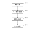
次に、ウォームシャフト2の製造方法の一例について説明する。図3に示すように、ウォームシャフト2の製造方法は、準備工程S110と、テーパ部形成工程S120と、歯部形成工程S130と、仕上げ工程S140と、を備える。ウォームシャフト2の製造方法では、図示するように、準備工程S110、テーパ部形成工程S120、歯部形成工程S130、仕上げ工程S140をこの順で行う。
Next, an example of a method for manufacturing the
準備工程S110では、図4に示すように、棒状の素材102Aを準備する。素材102Aは、その先端部に形成された円柱形状の小径円柱部111Aと、小径円柱部111Aから軸方向に延在する円柱形状の大径円柱部113Aと、を有する。大径円柱部113Aの外径は、小径円柱部111Aの外径よりも大きい。
In the preparation step S110, as shown in FIG. 4, a rod-shaped
テーパ部形成工程S120では、棒状の素材102Aの基端側を旋盤のチャックに支持させ、切削工具により、棒状の素材102Aに対して切削加工を施すことにより、大径円柱部113Aの先端部にテーパ部112B(図5参照)を形成する。
In the taper portion forming step S120, the base end side of the rod-shaped
図5に示すように、テーパ部形成工程S120により、テーパ部112Bを有する素材102Bが作製される。なお、テーパ部112Bは、円錐台形状であり、上記ウォームシャフト2のテーパ部112の歯部形成前の部位に相当する。テーパ部112Bから延在する大径円柱部113Bは、円柱形状であり、上記ウォームシャフト2の本体部113の歯部形成前の部位に相当する。
As shown in FIG. 5, the tapered portion forming step S120 produces a material 102B having a tapered
テーパ部112B(112)の外周面の傾斜角度θについて説明する。なお、テーパ部112B(112)の外周面の傾斜角度θとは、ウォームシャフト2の回転中心軸90に対する傾斜角度のことを指す。
The inclination angle θ of the outer peripheral surface of the tapered
ここで、実験により、テーパ部112B(112)の外周面の傾斜角度θが45度よりも大きいと、後述する歯部形成工程S130においてバリが発生しやすいことがわかった。このため、テーパ部112B(112)の外周面の傾斜角度θは、45度以下の角度に設定することが好ましい。テーパ部112B(112)の外周面の傾斜角度θが45度以下の角度である場合、後述する歯部形成工程S130において、効果的にバリが発生することを抑制することができる。
Here, it has been found from experiments that if the inclination angle θ of the outer peripheral surface of the tapered
一方、テーパ部112B(112)の外周面の傾斜角度θが30度未満であると、ウォームホイール1の歯部119に噛み合う歯部129の有効ねじ部の長さ(有効長)を十分に確保できないおそれがある。有効長を確保するために、ウォームシャフト2の軸長を長くする場合、上述のとおり、第2軸受11の可動量が増加し、歯打ち音が大きくなってしまうおそれがある。また、ウォームシャフト2の軸長が長くなることで、ウォーム減速機100が大型化してしまうおそれもある。このため、テーパ部112B(112)の外周面の傾斜角度θは、30度以上の角度に設定することが好ましい。これにより、ウォームシャフト2の軸長を短くすることができ、歯打ち音の低減及びウォーム減速機100の小型化を図ることができる。
On the other hand, if the inclination angle .theta. It may not be possible. When the axial length of the
このように、テーパ部112B(112)の外周面は、その傾斜角度θが、30度以上45度以下の角度に設定することが好ましい。また、テーパ部112B(112)の外周面は、その傾斜角度θが35度以上40度以下となるように形成することが、より好ましい。
Thus, it is preferable to set the inclination angle θ of the outer peripheral surface of the tapered
歯部形成工程S130では、テーパ部形成工程S120によって形成されたテーパ部112B(112)及びテーパ部112B(112)から延在する大径円柱部113B(本体部113)に歯部129(図6参照)を形成する。本実施形態では、ウォーム盤等の歯切り加工装置によって、テーパ部112B(112)を有する棒状の素材102Bに対して、歯切り加工を施すことにより、歯部129を形成する。歯切り加工装置は、図5において、二点鎖線で模式的に示すように、円板の外周に粗削り用の歯が形成された一枚歯の工具190を有する。
In the tooth portion forming step S130, the tapered
歯切り加工では、高速回転する工具190によって素材102Bが切削される。また、素材102Bは、その回転中心軸90を中心に低速で回転するとともに、回転中心軸90に沿う方向に低速で移動する。これにより、螺旋状の歯部129(図6参照)が形成される。なお、歯部129は、その歯底円直径が、円環状の壁面121の外径よりも大きくなるように形成される。歯切り加工は、素材102Bの基端側(図示右端側)の歯切り開始点P1から素材102Bの先端側(図示左端側)の歯切り終点P2までの所定幅L1の範囲で行われる。歯切り開始点P1とは、工具190による歯切り加工を開始する位置であり、歯切り終点P2とは、工具190による歯切り加工を終了する位置である。図示するように、歯切り終点P2は、テーパ部112B(112)に設定されている。
In gear cutting, the
図6に示すように、仕上げ工程S140では、所定幅L1の歯部形成範囲の内側の所定幅L2において、仕上げ加工が施される。本実施形態では、本体部113に形成された歯部129のみを仕上げるように、仕上げ加工が施される。仕上げ加工では、シェービングカッターを備える工具によって、本体部113における所定幅L2の歯部129に対して、シェービング加工を施すことにより、歯部129が仕上げられる。
As shown in FIG. 6, in the finishing step S140, finishing is performed in a predetermined width L2 inside the tooth forming range of the predetermined width L1. In this embodiment, finishing is performed so as to finish only the
なお、シェービング加工に代えて、一対のロールダイスを備えた転造装置(不図示)によって、転造加工を施すようにしてもよい。転造加工では、外周に仕上げ用の成形刃を有する一対のロールダイス間に素材を挟み込みつつ、一対のロールダイスを回転させ、素材を変形させることにより、歯部129が仕上げられる。仕上げ加工が施された所定幅L2の歯部(ねじ部)が、ウォームホイール1の歯部119と噛み合う有効ねじ部となる。
Instead of shaving, rolling may be performed by a rolling device (not shown) having a pair of roll dies. In the rolling process, the
本実施形態により得られる作用効果を本実施形態の比較例と比較して説明する。図7は、ウォームシャフト2の先端部を拡大して示す拡大図である。図7では、本実施形態に係るウォームシャフト2の先端部を実線で示し、本実施形態の比較例に係るウォームシャフトの先端部を二点鎖線で示している。
Effects obtained by this embodiment will be described in comparison with a comparative example of this embodiment. FIG. 7 is an enlarged view showing the tip of the
図7に示すように、本実施形態の比較例に係るウォームシャフトでは、挿入部111とテーパ部912との間に、円柱部915が形成されている。なお、本実施形態における壁面121から本体部113までの距離は、比較例における壁面121から本体部113までの距離と同一である。
As shown in FIG. 7 , in the worm shaft according to the comparative example of this embodiment, a
このため、本実施形態の比較例では、壁面121とテーパ部912とが円柱部915の軸方向長さの分だけ離れている。これに対して、本実施形態に係るウォームシャフト2では、壁面121がテーパ部112の外周面に直接接続されている。
Therefore, in the comparative example of the present embodiment, the
このため、本実施形態のテーパ部112の外周面の傾斜角度θは、比較例のテーパ部912の外周面の傾斜角度αに比べて小さくなる。比較例では、テーパ部912の外周面の傾斜角度αが45度よりも大きく、歯切り加工における歯切り終点近傍の歯が鋭利となるため、歯切り終点近傍においてバリが発生するおそれがある。これに対して、本実施形態では、テーパ部112の外周面の傾斜角度θが、比較例のテーパ部912の外周面の傾斜角度αに比べて小さく形成されている(例えば、傾斜角度θは35度程度)ので、歯切り終点P2近傍の歯が鋭利になることが抑制され、歯の剛性が確保される。このため、本実施形態では、歯切り終点P2近傍においてバリが発生することが抑制される。つまり、本実施形態によれば、比較例に対して、軸長を長くすることなく、バリの発生を抑制することができる。
Therefore, the inclination angle θ of the outer peripheral surface of the tapered
また、歯底129aがウォームシャフト2の回転中心軸90と平行かつ壁面121とテーパ部112との境界を通る直線SLよりも径方向内側に位置する場合であって、歯底129aの軸方向端部が壁面121に位置する場合では、歯切り終点が設定される壁面121の傾斜角度が90度であるため、歯切り終点近傍においてバリが発生するおそれがある。これに対して、本実施形態では、歯部129は、その歯底129aがウォームシャフト2の回転中心軸90と平行かつ壁面121とテーパ部112との境界を通る直線SLよりも径方向外側に位置するように、本体部113及びテーパ部112に形成され、歯底129aの軸方向端部がテーパ部112の外周面に位置しているのでバリの発生を抑制することができる。
Further, when the
上述した実施形態によれば、次の作用効果を奏する。 According to the embodiment described above, the following effects are obtained.
ウォームシャフト2は、壁面121からウォームシャフト2の基端側に向かうにしたがって外径が大きくなるように形成されるテーパ部112と、テーパ部112からウォームシャフト2の基端側に向かって延在する本体部113と、を備え、歯部129が、その歯底129aがウォームシャフト2の回転中心軸90と平行かつ壁面121とテーパ部112との境界を通る直線SLよりも径方向外側に位置するように、本体部113及びテーパ部112に形成されている。壁面121と、テーパ部112の外周面とが直接接続される構成であるため、ウォームシャフト2の軸長を長くすることなく、テーパ部112の外周面の傾斜角度θを小さく抑えることができる。
The
したがって、テーパ部112を有する棒状の素材102Bに対して歯切り加工を施すことにより、歯部129を形成する際に、テーパ部112でのバリの発生を抑制することができる。このため、バリを取り除くための処理を省略あるいは簡略化することができるので、ウォームシャフト2の製造コストの低減を図ることができる。つまり、本実施形態によれば、テーパ部112に歯部129を形成する際に、テーパ部112でのバリの発生を抑制可能なウォームシャフト2の製造方法を提供することができる。さらに、製造コストの低減を図ることのできるウォームシャフト2及びウォーム減速機100を提供することができる。
Therefore, by subjecting the rod-shaped
次のような変形例も本発明の範囲内であり、変形例に示す構成と上述の実施形態で説明した構成を組み合わせたり、以下の異なる変形例で説明する構成同士を組み合わせたりすることも可能である。 The following modifications are also within the scope of the present invention, and it is also possible to combine the configurations shown in the modifications with the configurations described in the above embodiments, or to combine the configurations described in the following different modifications. is.
<変形例1>
上記実施形態では、歯部形成工程S130に先立って、テーパ部形成工程S120を行う例について説明したが、本発明はこれに限定されない。予め、テーパ部112を有する棒状の素材102Bを準備し、テーパ部112及び本体部113に対して歯部129を形成するようにしてもよい。本変形例によれば、上記実施形態と同様、テーパ部112に歯部129を形成する際に、テーパ部112でのバリの発生を抑制可能なウォームシャフト2の製造方法を提供することができる。
<Modification 1>
In the above embodiment, an example in which the taper portion forming step S120 is performed prior to the tooth portion forming step S130 has been described, but the present invention is not limited to this. A rod-shaped material 102</b>B having a
<変形例2>
上記実施形態では、歯部形成工程S130において、外周に粗削り用の歯が形成された円板状の工具190を高速回転させることによって、素材102Bに歯切り加工を施す例について説明したが、本発明はこれに限定されない。円板状の工具190に代えて、内周に粗削り用の歯が形成された円環状の工具を高速回転させることによって、素材102Bに歯切り加工を施してもよい。
<
In the above-described embodiment, in the tooth portion forming step S130, the disk-shaped
<変形例3>
上記実施形態では、パワーステアリング装置10のウォーム減速機100に本発明を適用する例について説明したが、コンベア、ウィンチ、工作機械、建設機械等、種々の機械のウォーム減速機に本発明を適用することができる。
<
In the above embodiment, an example in which the present invention is applied to the
以上のように構成された本発明の実施形態の構成、作用、および効果をまとめて説明する。 The configuration, action, and effects of the embodiment of the present invention configured as described above will be collectively described.
ウォームシャフト2は、一対の軸受4,11によって先端側及び基端側が回転自在に支持され、ウォームホイール1に噛み合う歯部129を有するウォームシャフトであって、先端側に形成され、軸受11に挿入される挿入部111と、挿入部111の端部から径方向外側に立ち上がるように形成される壁面121と、壁面121から基端側に向かうにしたがって径が大きくなるように形成されるテーパ部112と、テーパ部112から基端側に向かって延在する本体部113と、を備え、歯部129は、歯部129の歯底129aがウォームシャフト2の回転中心軸90と平行かつ壁面121とテーパ部112との境界を通る直線SLよりも径方向外側に位置するように、本体部113及びテーパ部112に形成されている。
The
この構成では、壁面121から基端側に向かうにしたがって径が大きくなるようにテーパ部112が形成されているため、ウォームシャフト2の回転中心軸90に対するテーパ部112の外周面の傾斜角度θを小さく抑えることができる。これにより、テーパ部112に歯部129を形成する際に、テーパ部112でのバリの発生を抑制することができる。したがって、ウォームシャフト2の製造コストの低減を図ることができる。
In this configuration, since the tapered
ウォームシャフト2は、ウォームシャフト2の回転中心軸90に対するテーパ部112の外周面の傾斜角度θが、45度以下である。
In the
この構成では、テーパ部112に歯部129を形成する際に、テーパ部112でのバリの発生を効果的に抑制できる。
With this configuration, it is possible to effectively suppress the generation of burrs at the tapered
ウォームシャフト2は、ウォームシャフト2の回転中心軸90に対するテーパ部112の外周面の傾斜角度θが、30度以上である。
In the
この構成では、ウォームシャフト2の軸長を短くすることができる。
With this configuration, the axial length of the
ウォーム減速機100は、ウォームシャフト2の歯部129に噛み合う前記ウォームホイール1と、を備える。
The
この構成では、製造コストの低減を図ることのできるウォーム減速機100を提供することができる。
With this configuration, it is possible to provide the
上記ウォームシャフト2の製造方法は、テーパ部112(112B)を有する棒状の素材102Bに対して、テーパ部112(112B)及びテーパ部112(112B)から延在する本体部113(大径円柱部113B)に歯切り加工を施すことにより、歯部129を形成する歯部形成工程S130と、本体部113(大径円柱部113B)に形成された歯部129を仕上げる仕上げ工程S140と、を備える。
The manufacturing method of the
上記ウォームシャフト2の製造方法は、歯部形成工程S130に先立って、棒状の素材102Aにテーパ部112(112B)を形成するテーパ部形成工程S120をさらに備える。
The method for manufacturing the
これらの構成では、テーパ部112(112B)に歯部129を形成する際に、テーパ部112(112B)でのバリの発生を抑制可能なウォームシャフト2の製造方法を提供することができる。
With these configurations, it is possible to provide a method of manufacturing the
以上、本発明の実施形態について説明したが、上記実施形態は本発明の適用例の一部を示したに過ぎず、本発明の技術的範囲を上記実施形態の具体的構成に限定する趣旨ではない。 Although the embodiments of the present invention have been described above, the above embodiments merely show a part of application examples of the present invention, and the technical scope of the present invention is not limited to the specific configurations of the above embodiments. do not have.
1・・・ウォームホイール、2・・・ウォームシャフト、4・・・第1軸受(軸受)、11・・・第2軸受(軸受)、90・・・回転中心軸、100・・・ウォーム減速機、102A,102B・・・素材、111・・・挿入部、112,112B・・・テーパ部、113・・・本体部、113B・・・大径円柱部(本体部)、121・・・壁面、129・・・歯部、129a・・・歯底、142・・・内輪、S120・・・テーパ部形成工程、S130・・・歯部形成工程、S140・・・仕上げ工程、SL・・・直線、θ・・・傾斜角度
DESCRIPTION OF SYMBOLS 1... Worm wheel, 2... Worm shaft, 4... 1st bearing (bearing), 11... 2nd bearing (bearing), 90... Rotation center shaft, 100...
Claims (7)
前記先端側に形成され、前記軸受に挿入される挿入部と、
前記挿入部の端部から径方向外側に立ち上がるように形成される壁面と、
前記壁面から前記基端側に向かうにしたがって径が大きくなるように形成されるテーパ部と、
前記テーパ部から前記基端側に向かって延在する本体部と、を備え、
前記ウォームホイールは、前記ウォームシャフトと並んで配置されて前記ウォームシャフトの回転に伴い周方向に回転し、
前記歯部は、前記ウォームシャフトの略周方向に形成されるとともに、前記歯部の歯底が前記ウォームシャフトの回転中心軸と平行かつ前記壁面と前記テーパ部との境界を通る直線よりも径方向外側に位置するように、前記本体部及び前記テーパ部に形成されている
ことを特徴とするウォームシャフト。 A worm shaft rotatably supported at its distal end and proximal end by a pair of bearings, and having teeth meshing with a disk-shaped worm wheel,
an insertion portion formed on the distal end side and inserted into the bearing;
a wall surface formed to rise radially outward from an end of the insertion portion;
a taper portion formed so that the diameter increases from the wall surface toward the base end;
a main body portion extending from the tapered portion toward the proximal side,
The worm wheel is arranged side by side with the worm shaft and rotates in the circumferential direction as the worm shaft rotates,
The tooth portion is formed substantially in the circumferential direction of the worm shaft, and the tooth bottom of the tooth portion is parallel to the rotation center axis of the worm shaft and has a diameter larger than a straight line passing through the boundary between the wall surface and the tapered portion. The worm shaft is formed in the body portion and the tapered portion so as to be positioned outward in the direction.
前記ウォームシャフトの回転中心軸に対する前記テーパ部の外周面の傾斜角度は、45度以下である
ことを特徴とするウォームシャフト。 A worm shaft according to claim 1,
A worm shaft, wherein an inclination angle of the outer peripheral surface of the tapered portion with respect to the rotation center axis of the worm shaft is 45 degrees or less.
前記ウォームシャフトの回転中心軸に対する前記テーパ部の外周面の傾斜角度は、30度以上である
ことを特徴とするウォームシャフト。 A worm shaft according to claim 1 or claim 2,
A worm shaft, wherein an inclination angle of the outer peripheral surface of the tapered portion with respect to the rotation center axis of the worm shaft is 30 degrees or more.
前記ウォームシャフトの歯部に噛み合う前記ウォームホイールと、を備える
ことを特徴とするウォーム減速機。 a worm shaft according to any one of claims 1 to 3;
A worm reduction gear comprising: the worm wheel that meshes with the teeth of the worm shaft.
前記テーパ部を有する棒状の素材に対して、前記テーパ部及び前記テーパ部から延在する前記本体部に歯切り加工を施すことにより、前記歯部を形成する歯部形成工程を備え、 A tooth portion forming step of forming the tooth portions by subjecting the tapered portion and the main body portion extending from the tapered portion to gear cutting of the rod-shaped material having the tapered portion,
前記歯部形成工程では、円板の外周に歯が形成された工具により前記歯部が形成され、 In the tooth portion forming step, the tooth portion is formed by a tool having teeth formed on the outer periphery of a disc,
前記歯部形成工程において、前記ウォームシャフトの中心軸と、前記工具と、が成す鋭角は、前記ウォームシャフトの中心軸と、前記テーパ部の垂線と、が成す鋭角よりも大きいことを特徴とするウォームシャフトの製造方法。 In the tooth forming step, an acute angle formed between the central axis of the worm shaft and the tool is larger than an acute angle formed between the central axis of the worm shaft and the perpendicular to the tapered portion. Worm shaft manufacturing method.
前記テーパ部を有する棒状の素材に対して、前記テーパ部及び前記テーパ部から延在する前記本体部に歯切り加工を施すことにより、前記歯部を形成する歯部形成工程と、
前記本体部に形成された前記歯部を仕上げる仕上げ工程と、を備える
ことを特徴とするウォームシャフトの製造方法。 A method for manufacturing a worm shaft according to any one of claims 1 to 3,
a tooth forming step of forming the tooth by subjecting the tapered portion and the main body portion extending from the tapered portion to a tooth cutting process with respect to the rod-shaped material having the tapered portion;
and a finishing step of finishing the teeth formed on the main body.
前記歯部形成工程に先立って、棒状の素材に前記テーパ部を形成するテーパ部形成工程をさらに備える
ことを特徴とするウォームシャフトの製造方法。 A method for manufacturing a worm shaft according to claim 6 ,
A method of manufacturing a worm shaft, further comprising, prior to the tooth forming step, a tapered portion forming step of forming the tapered portion in a rod-shaped material.
Priority Applications (5)
| Application Number | Priority Date | Filing Date | Title |
|---|---|---|---|
| JP2019119919A JP7280763B2 (en) | 2019-06-27 | 2019-06-27 | Worm shaft, worm reduction gear, and method for manufacturing worm shaft |
| CN202080047103.7A CN114127440B (en) | 2019-06-27 | 2020-03-03 | Worm shaft, worm reducer, and method for manufacturing worm shaft |
| US17/617,551 US20220243798A1 (en) | 2019-06-27 | 2020-03-03 | Worm shaft, worm speed reducer, and manufacturing method of worm shaft |
| PCT/JP2020/008901 WO2020261652A1 (en) | 2019-06-27 | 2020-03-03 | Worm shaft, worm reduction gear, and method for manufacturing worm shaft |
| DE112020003087.3T DE112020003087T5 (en) | 2019-06-27 | 2020-03-03 | Worm shaft, worm reduction gear and manufacturing method of a worm shaft |
Applications Claiming Priority (1)
| Application Number | Priority Date | Filing Date | Title |
|---|---|---|---|
| JP2019119919A JP7280763B2 (en) | 2019-06-27 | 2019-06-27 | Worm shaft, worm reduction gear, and method for manufacturing worm shaft |
Publications (2)
| Publication Number | Publication Date |
|---|---|
| JP2021004667A JP2021004667A (en) | 2021-01-14 |
| JP7280763B2 true JP7280763B2 (en) | 2023-05-24 |
Family
ID=74060112
Family Applications (1)
| Application Number | Title | Priority Date | Filing Date |
|---|---|---|---|
| JP2019119919A Active JP7280763B2 (en) | 2019-06-27 | 2019-06-27 | Worm shaft, worm reduction gear, and method for manufacturing worm shaft |
Country Status (5)
| Country | Link |
|---|---|
| US (1) | US20220243798A1 (en) |
| JP (1) | JP7280763B2 (en) |
| CN (1) | CN114127440B (en) |
| DE (1) | DE112020003087T5 (en) |
| WO (1) | WO2020261652A1 (en) |
Families Citing this family (1)
| Publication number | Priority date | Publication date | Assignee | Title |
|---|---|---|---|---|
| US11745790B2 (en) * | 2021-09-13 | 2023-09-05 | Zf Automotive Germany Gmbh | Gear assembly and steering system |
Citations (4)
| Publication number | Priority date | Publication date | Assignee | Title |
|---|---|---|---|---|
| JP2001322554A (en) | 2000-05-17 | 2001-11-20 | Koyo Seiko Co Ltd | Electric power steering device |
| JP2010173380A (en) | 2009-01-27 | 2010-08-12 | Showa Corp | Electric power steering device |
| JP2014238141A (en) | 2013-06-07 | 2014-12-18 | 日本精工株式会社 | Worm reduction gear and dual pinion type electric power steering device |
| JP2015155745A (en) | 2013-09-20 | 2015-08-27 | 日本精工株式会社 | Worm reduction gear and dual pinion type electric power steering device |
Family Cites Families (25)
| Publication number | Priority date | Publication date | Assignee | Title |
|---|---|---|---|---|
| JP3077823B2 (en) * | 1991-05-20 | 2000-08-21 | 住友重機械工業株式会社 | Worm, worm wheel and method of manufacturing the same |
| US20050172744A1 (en) * | 2003-08-18 | 2005-08-11 | Nsk Ltd. | Reduction gear and method and apparatus for manufacturing the reduction gear concerned, and electric power steering system with the reduction gear concerned |
| JP2005091826A (en) * | 2003-09-18 | 2005-04-07 | Fuji Xerox Co Ltd | Image forming apparatus, driving mechanism for image forming apparatus and manufacturing method of worm gear set |
| JP4382454B2 (en) * | 2003-11-28 | 2009-12-16 | マブチモーター株式会社 | Small motor gear unit and manufacturing method thereof |
| DE102005008073B4 (en) * | 2004-02-24 | 2014-01-16 | Asmo Co., Ltd. | Motor having a control circuit part, a control circuit part and method for manufacturing the motor |
| JP2006103391A (en) * | 2004-10-01 | 2006-04-20 | Nsk Ltd | Electric power steering device |
| JP4834978B2 (en) * | 2004-11-16 | 2011-12-14 | 日本精工株式会社 | Worm wheel manufacturing method and worm reducer |
| JP4598594B2 (en) * | 2005-05-13 | 2010-12-15 | アスモ株式会社 | Geared motor |
| JP2008002526A (en) * | 2006-06-21 | 2008-01-10 | Asmo Co Ltd | Worm and motor device |
| US8905185B2 (en) * | 2009-12-23 | 2014-12-09 | Mando Corporation | Reducer of electric power steering apparatus |
| JP5053399B2 (en) * | 2010-02-22 | 2012-10-17 | ユニオンツール株式会社 | Rolling dies |
| BR112012023644B1 (en) * | 2010-03-24 | 2020-04-07 | Asmo Co Ltd | speed reduction mechanism, engine with speed reduction mechanism, and method for producing a speed reduction mechanism |
| JP6130988B2 (en) * | 2011-03-22 | 2017-05-17 | Kyb株式会社 | Power steering device |
| JP2016064790A (en) * | 2014-09-25 | 2016-04-28 | 株式会社ショーワ | Steering device |
| WO2016093247A1 (en) * | 2014-12-11 | 2016-06-16 | 日本精工株式会社 | Worm reducer and electrically driven assist device |
| KR102281681B1 (en) * | 2015-01-12 | 2021-07-27 | 주식회사 만도 | Reducer for vehicle |
| JP6167198B1 (en) * | 2016-03-25 | 2017-07-19 | Kyb株式会社 | Electric power steering device and method of manufacturing electric power steering device |
| JP6714845B2 (en) | 2016-05-24 | 2020-07-01 | 株式会社ジェイテクト | Worm reducer and electric power steering device |
| WO2018056296A1 (en) * | 2016-09-21 | 2018-03-29 | 日本精工株式会社 | Worm gear reducer |
| KR102566963B1 (en) * | 2016-10-05 | 2023-08-14 | 에이치엘만도 주식회사 | Reducer of Electric Power Steering Apparatus |
| KR102566335B1 (en) * | 2016-10-10 | 2023-08-14 | 에이치엘만도 주식회사 | Reducer of Electric Power Steering Apparatus |
| JP2018155301A (en) * | 2017-03-16 | 2018-10-04 | 株式会社ジェイテクト | Method for manufacturing worm reducer, worm reducer, and electric power steering device |
| CN207013815U (en) * | 2017-07-28 | 2018-02-16 | 瀚德汽车产品(苏州)有限公司 | A kind of automatic clearance adjuster worm screw part automatically removing burr equipment |
| JP6994241B2 (en) | 2018-01-10 | 2022-01-14 | 株式会社ユーパテンター | Plasma CVD equipment, plasma CVD method and manufacturing method of fine particles or electronic components |
| GB2611512A (en) * | 2021-07-23 | 2023-04-12 | Zf Steering Systems Poland Sp Z O O | A gearbox assembly for an electric power steering apparatus |
-
2019
- 2019-06-27 JP JP2019119919A patent/JP7280763B2/en active Active
-
2020
- 2020-03-03 WO PCT/JP2020/008901 patent/WO2020261652A1/en active Application Filing
- 2020-03-03 US US17/617,551 patent/US20220243798A1/en active Pending
- 2020-03-03 DE DE112020003087.3T patent/DE112020003087T5/en active Pending
- 2020-03-03 CN CN202080047103.7A patent/CN114127440B/en active Active
Patent Citations (4)
| Publication number | Priority date | Publication date | Assignee | Title |
|---|---|---|---|---|
| JP2001322554A (en) | 2000-05-17 | 2001-11-20 | Koyo Seiko Co Ltd | Electric power steering device |
| JP2010173380A (en) | 2009-01-27 | 2010-08-12 | Showa Corp | Electric power steering device |
| JP2014238141A (en) | 2013-06-07 | 2014-12-18 | 日本精工株式会社 | Worm reduction gear and dual pinion type electric power steering device |
| JP2015155745A (en) | 2013-09-20 | 2015-08-27 | 日本精工株式会社 | Worm reduction gear and dual pinion type electric power steering device |
Also Published As
| Publication number | Publication date |
|---|---|
| US20220243798A1 (en) | 2022-08-04 |
| JP2021004667A (en) | 2021-01-14 |
| WO2020261652A1 (en) | 2020-12-30 |
| CN114127440B (en) | 2024-02-27 |
| DE112020003087T5 (en) | 2022-03-10 |
| CN114127440A (en) | 2022-03-01 |
Similar Documents
| Publication | Publication Date | Title |
|---|---|---|
| JP4875601B2 (en) | Barrel-shaped worm-like tool | |
| JP2008281063A (en) | Ball screw mechanism | |
| JP4984607B2 (en) | Steering device | |
| JP2010253674A (en) | Method and apparatus for removing secondary burr on end-cut workpiece wheel | |
| JP4483257B2 (en) | Method for processing joint of ball screw and its nut and electric power steering apparatus | |
| JP7280763B2 (en) | Worm shaft, worm reduction gear, and method for manufacturing worm shaft | |
| JP4640135B2 (en) | Ball screw and ball screw nut manufacturing method | |
| JP2004510591A (en) | Method and apparatus for manufacturing a cutting tool having a groove | |
| JP4888760B2 (en) | Screw shaft forming method and screw shaft of ball screw mechanism | |
| JP5163024B2 (en) | Worm wheel manufacturing method and worm reducer | |
| JP5536521B2 (en) | Connection configuration of tool wheel and tool holding fixture | |
| JP7124891B2 (en) | Linear drive shaft for electric power steering device, electric power steering device, and manufacturing method thereof | |
| JP5392388B2 (en) | Worm wheel manufacturing method and worm reducer | |
| JP6187280B2 (en) | Differential gear device and manufacturing method thereof | |
| JP5772586B2 (en) | Ball screw nut | |
| JP7211433B2 (en) | Linear motion shaft for steering device, steering device, and manufacturing method thereof | |
| JP5091041B2 (en) | Power steering device, pinion shaft, and method of manufacturing pinion shaft | |
| JP5282810B2 (en) | Ball screw mechanism | |
| JP5908358B2 (en) | Electric power steering device | |
| JP2016112955A (en) | Power steering device | |
| JP2009192058A (en) | Worm wheel and its manufacturing method | |
| JP2005224911A (en) | Chuck holding method for restraining perpendicularity in turning of inner peripheral surface of forged angular bearing inner race blank | |
| JP2010001937A (en) | Worm shaft, method of manufacturing thereof, and electric power steering device | |
| JP2013061014A (en) | Method for manufacturing shaft coupling | |
| JP2000158230A (en) | Broach |
Legal Events
| Date | Code | Title | Description |
|---|---|---|---|
| A621 | Written request for application examination |
Free format text: JAPANESE INTERMEDIATE CODE: A621 Effective date: 20211221 |
|
| A131 | Notification of reasons for refusal |
Free format text: JAPANESE INTERMEDIATE CODE: A131 Effective date: 20221213 |
|
| A601 | Written request for extension of time |
Free format text: JAPANESE INTERMEDIATE CODE: A601 Effective date: 20230202 |
|
| A521 | Request for written amendment filed |
Free format text: JAPANESE INTERMEDIATE CODE: A523 Effective date: 20230404 |
|
| TRDD | Decision of grant or rejection written | ||
| A01 | Written decision to grant a patent or to grant a registration (utility model) |
Free format text: JAPANESE INTERMEDIATE CODE: A01 Effective date: 20230418 |
|
| A61 | First payment of annual fees (during grant procedure) |
Free format text: JAPANESE INTERMEDIATE CODE: A61 Effective date: 20230512 |
|
| R151 | Written notification of patent or utility model registration |
Ref document number: 7280763 Country of ref document: JP Free format text: JAPANESE INTERMEDIATE CODE: R151 |
|
| S533 | Written request for registration of change of name |
Free format text: JAPANESE INTERMEDIATE CODE: R313533 |
|
| R350 | Written notification of registration of transfer |
Free format text: JAPANESE INTERMEDIATE CODE: R350 |