WO2017163547A1 - 圧力制御装置および変速機 - Google Patents
圧力制御装置および変速機 Download PDFInfo
- Publication number
- WO2017163547A1 WO2017163547A1 PCT/JP2017/000918 JP2017000918W WO2017163547A1 WO 2017163547 A1 WO2017163547 A1 WO 2017163547A1 JP 2017000918 W JP2017000918 W JP 2017000918W WO 2017163547 A1 WO2017163547 A1 WO 2017163547A1
- Authority
- WO
- WIPO (PCT)
- Prior art keywords
- pressure
- control device
- pilot valve
- pilot
- output
- Prior art date
- Legal status (The legal status is an assumption and is not a legal conclusion. Google has not performed a legal analysis and makes no representation as to the accuracy of the status listed.)
- Ceased
Links
Images



Classifications
-
- F—MECHANICAL ENGINEERING; LIGHTING; HEATING; WEAPONS; BLASTING
- F16—ENGINEERING ELEMENTS AND UNITS; GENERAL MEASURES FOR PRODUCING AND MAINTAINING EFFECTIVE FUNCTIONING OF MACHINES OR INSTALLATIONS; THERMAL INSULATION IN GENERAL
- F16H—GEARING
- F16H61/00—Control functions within control units of change-speed- or reversing-gearings for conveying rotary motion ; Control of exclusively fluid gearing, friction gearing, gearings with endless flexible members or other particular types of gearing
-
- F—MECHANICAL ENGINEERING; LIGHTING; HEATING; WEAPONS; BLASTING
- F16—ENGINEERING ELEMENTS AND UNITS; GENERAL MEASURES FOR PRODUCING AND MAINTAINING EFFECTIVE FUNCTIONING OF MACHINES OR INSTALLATIONS; THERMAL INSULATION IN GENERAL
- F16H—GEARING
- F16H63/00—Control outputs from the control unit to change-speed- or reversing-gearings for conveying rotary motion or to other devices than the final output mechanism
- F16H63/02—Final output mechanisms therefor; Actuating means for the final output mechanisms
- F16H63/04—Final output mechanisms therefor; Actuating means for the final output mechanisms a single final output mechanism being moved by a single final actuating mechanism
-
- F—MECHANICAL ENGINEERING; LIGHTING; HEATING; WEAPONS; BLASTING
- F16—ENGINEERING ELEMENTS AND UNITS; GENERAL MEASURES FOR PRODUCING AND MAINTAINING EFFECTIVE FUNCTIONING OF MACHINES OR INSTALLATIONS; THERMAL INSULATION IN GENERAL
- F16K—VALVES; TAPS; COCKS; ACTUATING-FLOATS; DEVICES FOR VENTING OR AERATING
- F16K31/00—Actuating devices; Operating means; Releasing devices
- F16K31/02—Actuating devices; Operating means; Releasing devices electric; magnetic
- F16K31/06—Actuating devices; Operating means; Releasing devices electric; magnetic using a magnet, e.g. diaphragm valves, cutting off by means of a liquid
Definitions
- the present invention relates to a pressure control device for controlling the pressure of a pressure medium and a transmission using the same.
- the transmission system of an automobile is equipped with a system for controlling the hydraulic pressure supplied to the load.
- the hydraulic pressure supplied to the load is measured by a pressure sensor, and the control circuit drives the pressure control device using the pressure sensor value and the target pressure value to control the hydraulic pressure supplied to the load.
- Patent Document 1 states that “the hydraulic oil supplied to the secondary pulley 21 is regulated to the line pressure PL via the line pressure control valve 42 and regulated to the secondary pressure Ps via the secondary pressure control valve 43.
- the secondary pressure control valve 43 includes a push plug 93 that biases the spool valve shaft 92, the line pressure PL is introduced into the pilot pressure chamber 43d, and the secondary pressure Ps is introduced into the pilot pressure chamber 43e.
- Patent Document 1 an urging piece for urging the spool valve shaft toward the communication position by a spring force is provided in the control valve, and the primary side control pressure chamber defined between the spool valve shaft and the urging piece is provided in the control valve.
- the present application includes a plurality of means for solving the above-described problems.
- a pressure control device that controls the pressure of a pressure medium supplied to a plurality of actuators that operate a transmission includes the plurality of actuators”.
- a plurality of transmission systems provided for each, each pressure control device includes a movable part driven by a magnetic circuit, and a pressure output unit for outputting an output pressure generated by the operation of the movable part, Furthermore, a pressure measuring unit having a pressure sensor for measuring the pressure of the pressure medium supplied to the actuator is incorporated. ”
- the pressure sensor casing can be made common with the pressure control valve casing, thereby reducing the size. it can. Further, by introducing the load pressure into the pressure measuring unit and performing the control based on the load pressure, the load pressure control similar to the conventional one can be performed. Problems, configurations, and effects other than those described above will be clarified by the following description of embodiments.
- FIG. 6 is a diagram illustrating a structure example of a pilot valve in the second embodiment. It is a figure showing the example of a structure of the pressure control apparatus in Example 3.
- FIG. 6 is a diagram illustrating a structure example of a pilot valve in a third embodiment.
- FIG. 1 is a diagram showing a configuration example of an automobile drive device.
- the power supplied from the engine 1 is transmitted to the axle 11 via the transmission 2 and rotates the wheels 12a and 12b.
- the transmission 2 includes a torque converter 3, a forward / reverse switching mechanism 4, pulleys 5 a and 5 b, a belt 6, a pressure control device 7, a reduction gear 9, and a differential gear 10.
- the torque converter 3 is a device that amplifies the power supplied from the engine 1 and transmits the amplified power to the forward / reverse switching mechanism 4.
- the forward / reverse switching mechanism 4 receives a shift signal 13 from the outside, switches the rotational direction of the power output from the torque converter 3 to the forward direction or the reverse direction, or cuts off the power supplied to the pulley 5a. To do.
- the pulleys 5 a and 5 b rotate during operation, and transmit the power supplied from the forward / reverse switching mechanism 3 to the reduction gear 9.
- the groove widths of the pulleys 5a and 5b change in response to the load pressures 8a and 8b output from the pressure control device 7. Due to the change in the groove width, the length of the belt 6 changes, and the transmission gear ratio (the ratio of the power supplied from the forward / reverse switching mechanism to the power supplied to the reduction gear) changes.
- a continuously variable transmission is used as an example of the transmission 2, but other transmissions such as a manual transmission (MT) or an automatic transmission (MT) are also exemplified.
- AT Automatic Transmission
- gears are used in place of the pulleys 5a and 5b as means for changing the gear ratio.
- the pressure control device 7 calculates the load pressures 8a and 8b based on the accelerator pedal opening 14, the engine speed 15 and the vehicle speed 16 from the outside, and controls the load pressures 8a and 8b applied to the pulleys 5a and 5b. .
- the internal structure of the pressure control device 7 will be described later with reference to FIG.
- the reduction gear 9 reduces the power supplied from the pulley 5 b and transmits it to the differential gear 10.
- the differential gear 10 distributes the power supplied from the reduction gear 9 to the left and right wheels 12a and 12b through the axle 11.
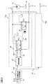
- FIG. 2 is a diagram illustrating a configuration example of the pressure control device according to the first embodiment.
- the pressure control device 7 includes a tank 70, a pump 71, a target pressure generation circuit 73, and pressure control circuits 75a and 75b.
- the tank 70 is a container for accumulating oil to be supplied into the pressure control device 7.
- Pump 71 draws up oil from tank 70 and pressurizes the drawn up oil to generate line pressure 72.
- the target pressure generating circuit 73 calculates the target pressures 74a and 74b based on the accelerator pedal opening 14, the engine speed 15 and the vehicle speed 16 inputted from the outside, and outputs them to the pressure control circuits 75a and 75b, respectively.
- the pressure control circuits 75a and 75b control the load pressures 8a and 8b according to the target pressures 74a and 74b input from the target pressure generation circuit 73, respectively.
- the pressure control circuit 75a has a pilot valve 80, a secondary valve 81, and a control circuit 82 therein. Since the internal circuit configuration of the pressure control circuit 75b is the same as that of the pressure control circuit 75a, the internal circuit of the pressure control circuit 75b is omitted.
- the pilot valve 80 controls the amount of oil flowing from the line pressure 72 to the pilot pressure 84 and the amount of oil discharged from the pilot pressure 84 to the tank 70 based on the drive signal 83 input from the control circuit 82.
- the pressure of the pilot pressure 84 is controlled.
- the pilot valve 80 has a pressure sensor inside and measures the load pressure 8a. The measured pressure value 85 is transmitted to the control circuit 82.
- the secondary valve 81 controls the amount of oil flowing from the line pressure 72 to the load pressure 8a and the amount of oil discharged from the load pressure 8a portion to the tank 2 based on the pilot pressure 84 supplied from the pilot valve 80. Thereby, the load pressure 8a is controlled.
- pilot pressure 84 output from the pilot valve 80 to the pulleys 5a and 5b as the load pressures 8a and 8b without using the secondary valve 81.
- the diameter of the pilot valve 80 must be increased in order to cope with a large flow rate.
- the diameter of the movable portion 92 is also increased, and it is necessary to increase the amount of current flowing through the magnetic circuit 91 in order to operate the movable portion.
- the control circuit 82 generates a drive signal 83 based on the target pressure 74 a output from the target pressure generation circuit 73 and the pressure value 85 output from the pilot valve 80, and outputs this drive signal 83 to the pilot valve 80.
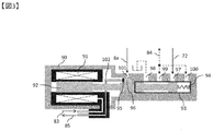
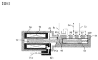
- FIG. 3 is a diagram showing an example of the internal structure of the pilot valve 80 in the first embodiment.
- the pilot valve 80 in FIG. 3 is covered with a casing 90, and includes a magnetic circuit 91, a movable portion 92, a pressure output portion 93, a spring 94, a pressure sensor 95, a pressure measuring portion 96, an input port 97, a discharge port 98, and an output.
- a port 99, a feedback port 100, a measurement port 101, and a wiring 102 are provided.
- the magnetic circuit 91 receives the drive signal 83 from the control circuit 82 and generates a magnetic field around it.
- the movable portion 92 receives the force due to the magnetic field generated by the magnetic circuit 91 and the force due to the spring 94, and drives left and right in the case of the structural example of FIG.
- the oil flows into the pressure output section 93 from the line pressure 72 through the input port 97 and is discharged into the tank 70 through the discharge port 98.
- the amount of oil inflow and discharge varies depending on the position of the movable portion 92. Therefore, the pilot pressure 84 output from the output port 99 also changes according to the position of the movable portion 92. Further, the pilot pressure 84 is inputted to the portion where the spring 94 is located through the feedback port 100.
- the oil in the pressure output portion 93 is discharged to the tank 70 through the discharge port 98, so that the pilot pressure 84 decreases.
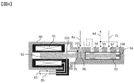
- the oil flows from the line pressure 72 into the pressure output portion 93 through the input port 97, so that the pilot pressure 84 rises.
- the pilot pressure 84 increases or decreases depending on the difference between the amount of oil flowing in through the input port 97 and the amount of oil discharged through the discharge port 98. To do.
- the pressure sensor 95 measures the hydraulic pressure in the pressure measuring unit 96 and transmits the measured pressure value 85 to the control circuit 82 via the wiring 102.
- the conventional pressure sensor for example, a sensor using a strain gauge or a sensor using a capacitance is used.
- the conventional pressure sensor includes a housing 200, an input port 201, a sensor element 202, an internal wiring 203, an electronic circuit 204, and an output wiring 205.
- the sensor element 202 converts the pressure input from the input port 201 into an electric signal, and the electric signal is corrected and amplified by the electronic circuit 204 and output to the outside via the output wiring 205.
- the pressure sensor 95 included in the pilot valve 80 is obtained by extracting only the sensor element 202, the internal wiring 203, and the electronic circuit 204 from the conventional pressure sensor shown in FIG.
- the casing 200 portion of the pressure sensor is removed by unifying it with the casing 90 of the pilot valve 80, and the size of the pressure sensor 95 is made smaller than before.
- Oil is introduced into the pressure measuring unit 96 from the load pressure 8a through the measurement port 101.
- the pressure measuring unit 96 has a structure in which internal oil does not come into contact with the movable unit 92. By doing so, it is possible to suppress the oil in the pressure measurement unit 96 from moving with the left and right movements of the movable unit 52, and to stably measure the hydraulic pressure in the pressure measurement unit 96.
- the pilot valve 80 includes the pressure measuring unit 96 and the pressure sensor 95 inside, and the load pressure 8a is introduced into the pressure measuring unit 96, thereby the load pressure 8a.
- the control is implemented.
- the pressure sensor 95 can be made smaller than before by sharing the housing portion with the pilot valve 80.
- the load pressures 8a and 8b can be controlled while downsizing the entire pressure control device 7.
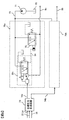
- FIG. 6 shows a configuration example of the pressure control device in the second embodiment.
- the pressure control device in FIG. 6 has pilot valves 80a and 80b different from the pilot valve 80 in the first embodiment.
- the pilot valve 80a controls the pressure of the pilot pressure 84 by controlling the amount of oil flowing from the line pressure 72 to the pilot pressure 84 based on the drive signal 83a output from the control circuit 82.
- the pilot valve 80a has a pressure sensor inside and measures the load pressure 8a. The measured pressure value 85a is transmitted to the control circuit 82.
- the pilot valve 80 b controls the pressure of the pilot pressure 84 by controlling the amount of oil discharged from the pilot pressure 84 to the tank 70 based on the drive signal 83 b output from the control circuit 82.
- the pilot valve 80b has a pressure sensor inside, and measures the load pressure 8a. The measured pressure value 85b is transmitted to the control circuit 82.
- the control circuit 82 generates drive signals 83a and 83b based on the target pressure 74a output from the target pressure generation circuit 73, the pressure value 85a transmitted from the pilot valve 80a, and the pressure value 85b transmitted from the pilot valve 80b.
- the drive signals 83a and 83b are output to the pilot valves 80a and 80b, respectively.
- control circuit 82 does not necessarily have to use both the pressure values 85a and 85b for determining the drive signals 83a and 83b.
- the control circuit 82 may determine the drive signals 83a and 83b using the target pressure 74a and one of the pressure values 85a and 85b.
- FIG. 7 is a view showing an example of the structure of the pilot valve 80a in the second embodiment. Unlike the pilot valve 80 of the first embodiment, the pilot valve 80 a does not have the discharge port 98. The other structure is the same as that of the pilot valve 80 of the first embodiment.
- the input port 97 is connected to the line pressure 72 and the output port 99 is connected to the pilot pressure 84.
- the pilot valve 80b has the same internal structure as the pilot valve 80a, but the port connection destination is different.
- the input port 97 is connected to the pilot pressure 84, and the output port 99 is connected to the tank 70.
- the present embodiment shows a configuration in which the pilot valve 80 which is the linear solenoid type in the first embodiment is replaced with the pilot valves 80a and 80b which are ON / OFF valve types. Also in this configuration, as in the first embodiment, the load pressure control can be performed while reducing the size of the pressure control device by integrating the pilot valve 80a and the pressure sensor 95.
- FIG. 8 shows a configuration example of the pressure control device according to the third embodiment.
- the pressure control device in FIG. 8 has a pilot valve 80c different from the pilot valve 80 in the first embodiment. Further, in the pressure control apparatus of the present embodiment, the target pressure 74a output from the target pressure generation circuit 73 is directly input to the pilot valve 80c.
- the pilot valve 80 c controls the amount of oil flowing from the line pressure 72 to the pilot pressure 84 and the amount of oil discharged from the pilot pressure 84 to the tank 70 based on the target pressure 74 a output from the target pressure generating circuit 73.
- the pilot pressure 84 is controlled.
- the pilot valve 80 has a pressure sensor inside and measures the load pressure 8a.
- FIG. 9 is a view showing a structure example of the pilot valve 80c in the third embodiment.
- the pilot valve 80c includes a pressure sensor 95a different from the pressure sensor 95 included in the pilot valve 80c in the first embodiment.
- the pilot valve 80c also has a control circuit 103 inside.
- the pressure sensor 95 in the first embodiment includes the sensor element 202, the internal wiring 203, and the electronic circuit 204 in FIG. 5, but the pressure sensor 95a in the third embodiment has only the sensor element 202.
- the electronic circuit 203 and the internal wiring 203 can be eliminated by moving the correction and amplification function of the sensor signal, which has been conventionally performed by the electronic circuit 203, into the control circuit 103. Further, in addition to the first embodiment, the electronic circuit 203 can be further downsized and reduced in size. Costs are being reduced.
- the control circuit 103 inside the pilot valve 80c generates a drive signal based on the target pressure 74a output from the target pressure generation circuit 73 and the pressure value measured by the pressure sensor 95a, like the control circuit 82 in the first embodiment. Then, the magnetic circuit 51 is driven.
- the control circuit 103 also has a sensor signal correction and amplification function of the electronic circuit 204 that the pressure sensor 95 has in the first embodiment.
- the control circuit 103 is incorporated in the pilot valve 80c.
- the control circuit 103 has a pressure sensor value correction and signal amplification function in addition to the pressure control function.
- the function divided by the electronic circuit 204 and the control circuit 82 in the pressure sensor 95 is integrated as one pressure control circuit 103, thereby simplifying the structure of the pressure sensor 95a. Therefore, it is possible to mount it at a smaller size and at a lower cost than the pressure sensor 95. Thereby, further downsizing and cost reduction of the pressure control device can be realized.
- this invention is not limited to the above-mentioned Example, Various modifications are included.
- the above-described embodiment has been described with respect to a hydraulic circuit, the same effect can be obtained for circuits using other pressure media such as air or water.
- the above-described embodiments have been described in detail for easy understanding of the present invention, and are not necessarily limited to those having all the configurations described. Further, a part of the configuration of one embodiment can be replaced with the configuration of another embodiment, and the configuration of another embodiment can be added to the configuration of one embodiment. Further, it is possible to add, delete, and replace other configurations for a part of the configuration of each embodiment.
- Each of the above-described configurations, functions, processing units, processing means, and the like may be realized by hardware by designing a part or all of them with, for example, an integrated circuit.
- Each of the above-described configurations, functions, and the like may be realized by software by interpreting and executing a program that realizes each function by the processor.
- Information such as programs, tables, and files for realizing each function can be stored in a memory, a hard disk, a recording device such as an SSD (Solid State Drive), or a recording medium such as an IC card, an SD card, or a DVD.
Landscapes
- Engineering & Computer Science (AREA)
- General Engineering & Computer Science (AREA)
- Mechanical Engineering (AREA)
- Control Of Fluid Pressure (AREA)
- Magnetically Actuated Valves (AREA)
- Gear-Shifting Mechanisms (AREA)
- Control Of Transmission Device (AREA)
Abstract
圧力制御装置を小型化しつつ、負荷圧力の制御を実施する 変速機を動作させる複数のアクチュエータに供給される圧力媒体の圧力を制御する圧力制御装置が前記複数のアクチュエータごとに複数設けられる変速機システムであって、 前記各圧力制御装置は、磁気回路によって駆動される可動部と、前記可動部の動作によって生成される出力圧力を出力する圧力出力部とを備え、さらに、前記アクチュエータに供給される圧力媒体の圧力を測定する圧力センサを有する圧力測定部が組み込まれることを特徴とする変速機システム
Description
本発明は圧力媒体の圧力を制御するための圧力制御装置とそれを用いた変速機に関する。
自動車の変速機装置には、負荷に供給する油圧を制御するためのシステムが搭載されている。これらの装置では、負荷への供給油圧を圧力センサによって測定し、この圧力センサ値と目標圧力値を用いて、制御回路が圧力制御装置を駆動させ、負荷に供給する油圧を制御している。
近年、燃費や乗り心地向上のために、変速機装置内に搭載される負荷の数が増えている。また、車両全体のコンパクト化などに伴い、エンジンルームの容積を削減する動きがあり、変速機装置の小型化も要求されている。そのため、変速機装置は小型化を行いつつ、制御負荷の増加に対応していかなければならない状況となっている。
この技術分野の背景技術として、特開2006-307927(特許文献1)がある。特許文献1には、「セカンダリプーリ21に供給される作動油は、ライン圧制御弁42を介してライン圧PLに調圧され、セカンダリ圧制御弁43を介してセカンダリ圧Psに調圧される。セカンダリ圧制御弁43は、スプール弁軸92を付勢するプッシュプラグ93を備え、パイロット圧室43dにはライン圧PLが導入され、パイロット圧室43eにはセカンダリ圧Psが導入される。ライン圧PLが低くプッシュプラグ93とスプール弁軸92とが接するときには、ライン圧PLがスプール弁軸92に作用しないため、減圧されたライン圧PLがセカンダリ圧Psとして出力される。ライン圧PLが高くプッシュプラグ93とスプール弁軸92とが離れるときには、ライン圧PLがスプール弁軸92に作用するため、ライン圧PLがそのままセカンダリ圧Psとして出力される」と記載されている。
特許文献1では、制御弁内にバネ力によってスプール弁軸を連通位置に向けて付勢する付勢駒を設け、スプール弁軸と付勢駒との間に区画される一次側制御圧室に入力圧を導入する構成にすることで、入力圧によって制御弁の出力圧の特性を変化させることを可能にしている。また、この制御弁を圧力制御装置に用いることで、プーリー側の受圧面積を小さくでき、圧力制御装置の小型化を実現している。
しかし、本特許文献の効果はプーリー側受圧面積の低減のみであり、制御に必要な回路構成素子、例えば圧力センサや制御弁を除外した場合と比べて小型化の効果が小さい。
上記課題を解決するために、例えば特許請求の範囲に記載の構成を採用する。
本願は上記課題を解決する手段を複数含んでいるが、その一例を挙げるならば、「変速機を動作させる複数のアクチュエータに供給される圧力媒体の圧力を制御する圧力制御装置が前記複数のアクチュエータごとに複数設けられる変速機システムであって、前記各圧力制御装置は、磁気回路によって駆動される可動部と、前記可動部の動作によって生成される出力圧力を出力する圧力出力部とを備え、さらに、前記アクチュエータに供給される圧力媒体の圧力を測定する圧力センサを有する圧力測定部が組み込まれること」を特徴とする。
本発明によれば、圧力制御弁内に圧力測定部を設けてそこに圧力センサを一体化することで、圧力センサの筐体を圧力制御弁の筐体と共通化し、小型化を行うことができる。また、負荷圧力を圧力測定部に導入し、負荷圧力に基づいた制御を行うことで従来と同様の負荷圧力制御が可能となる。上記以外の課題、構成及び効果は、以下の実施形態の説明により明らかにされる。
以下、図面を用いて実施例を説明する。
本実施例では、圧力制御装置を小型化しつつ、負荷圧力の制御が可能な圧力制御装置の例を示す。
図1は、自動車の駆動装置の構成例を表した図である。エンジン1から供給される動力は、変速機2を介して車軸11へと伝達され、車輪12aおよび12bを回転させる。変速機2は、内部にトルクコンバータ3、前進/後退切替機構4、プーリー5aおよび5b、ベルト6、圧力制御装置7、減速歯車9、差動歯車10を有している。
トルクコンバータ3は、エンジン1から供給される動力を増幅させて、前進/後退切替機構4に伝達する装置である。
前進/後退切替機構4は、外部からのシフト信号13を受けて、トルクコンバータ3から出力された動力の回転方向を前進方向や後退方向に切り替えたり、あるいはプーリー5aに供給する動力を遮断したりする。
プーリー5aおよび5bは、稼働中は回転しており、前進/後退切替機構3から供給された動力を減速歯車9へ伝達する。プーリー5aおよび5bの溝幅は、圧力制御装置7から出力される負荷圧力8aおよび8bを受けて変化する。この溝幅の変化により、ベルト6の長さが変わり、変速比(前進/後退切替機構から供給される動力と減速歯車へ供給する動力の比率)が変化する。
なお、本実施例では、変速機2として無段変速機(CVT:Continuously Variable Transmission)を例に挙げているが、他の変速機、例えば手動変速機(MT:Manual Transmisson)や自動変速機(AT:Automatic Transmission)でも良い。手動変速機や自動変速機の場合には、変速比を変える手段として、プーリー5aおよび5bの代わりに歯車が用いられる。
圧力制御装置7は、外部からのアクセルペダル開度14、エンジン回転数15、車速16をもとに負荷圧力8aおよび8bを計算し、プーリー5aおよび5bに与えられる負荷圧力8aおよび8bを制御する。圧力制御装置7の内部構造は、図2において後述する。
減速歯車9は、プーリー5bから供給された動力を小さくし、差動歯車10へ伝達する。差動歯車10は、減速歯車9から供給された動力を車軸11を通して左右の車輪12aおよび12bへ分配する。
図2は、実施例1における圧力制御装置の構成例を示した図である。圧力制御装置7は、内部にタンク70、ポンプ71、目標圧力生成回路73、圧力制御回路75aおよび75bを有している。
タンク70は、圧力制御装置7内部に供給する油を蓄積するための容器である。
ポンプ71は、タンク70から油をくみ上げ、くみ上げた油を加圧してライン圧72を生成する。
目標圧力生成回路73は、外部から入力されたアクセルペダル開度14、エンジン回転数15、車速16をもとに、目標圧力74aおよび74bを計算し、圧力制御回路75aおよび75bにそれぞれ出力する。
圧力制御回路75aおよび75bは、目標圧力生成回路73から入力された目標圧力74aおよび74bに従って、負荷圧力8aおよび8bの制御をそれぞれ行う。
圧力制御回路75aは、内部にパイロット弁80、二次弁81、制御回路82を有している。圧力制御回路75bの内部回路構成は圧力制御回路75aと同様であるため、圧力制御回路75bの内部回路は省略している。
パイロット弁80は、制御回路82から入力される駆動信号83をもとに、ライン圧72からパイロット圧84への油の流入量とパイロット圧84からタンク70への油の排出量を制御し、パイロット圧84の圧力を制御する。また、パイロット弁80は内部に圧力センサを有しており、負荷圧力8aを測定している。この測定した圧力値85は、制御回路82に伝達される。
二次弁81は、パイロット弁80から供給されるパイロット圧84に基づいて、ライン圧72から負荷圧力8aへの油の流入量と負荷圧力8a部分からタンク2への油の排出量を制御し、それによって負荷圧力8aを制御している。
なお、二次弁81を利用せず、パイロット弁80から出力されるパイロット圧84を負荷圧力8aおよび8bとしてプーリー5aおよび5bに供給することも可能である。ただし、プーリー5aおよび5bの駆動に多量の油が必要である場合に二次弁81を取り除くと、大流量に対応するためにパイロット弁80の径を大きくしなければならない。パイロット弁80の径を大きくすると、可動部92の径も大きくなり、可動部を動作させるために磁気回路91に流す電流量を多くする必要がある。そうなると、大電流を流せるように制御回路82を設計する必要がある他、電流量の増加に伴う発熱も問題となる。このように、負荷に供給する油の流量が多い場合には、二次弁81を用いて負荷圧力8aおよび8bを供給することが望ましい。
制御回路82は、目標圧力生成回路73から出力された目標圧力74aとパイロット弁80から出力される圧力値85に基づいて駆動信号83を生成し、この駆動信号83をパイロット弁80に出力する。
図3は、実施例1におけるパイロット弁80の内部構造例を示した図である。図3のパイロット弁80は筐体90で覆われ、内部に磁気回路91、可動部92、圧力出力部93、ばね94、圧力センサ95、圧力測定部96、入力ポート97、排出ポート98、出力ポート99、フィードバックポート100、測定用ポート101、配線102を有する。
磁気回路91は、制御回路82からの駆動信号83を受けて、周囲に磁界を発生させる。可動部92は、磁気回路91が発生する磁界による力と、ばね94による力を受けて、図3の構造例の場合には左右に駆動する。
圧力出力部93には、入力ポート97を通してライン圧72から油が流入し、排出ポート98を通してタンク70に油が排出される。この油の流入量及び排出量は可動部92の位置に応じて変化する。そのため、出力ポート99から出力されるパイロット圧84も可動部92の位置に応じて変化する。また、フィードバックポート100を通して、ばね94がある部分にはパイロット圧84を入力している。
可動部92が図3で示した位置である場合、圧力出力部93内の油は排出ポート98を通してタンク70に排出されるため、パイロット圧84は低下する。可動部92が図4で示した位置にある場合、入力ポート97を通してライン圧72から圧力出力部93内に油が流入するため、パイロット圧84は上昇する。可動部92が図3と図4で示した位置の中間にある場合、入力ポート97を通して流入する油量と排出ポート98を通して排出される油量の差に応じて、パイロット圧84は上昇もしくは低下する。
圧力センサ95は、圧力測定部96内の油圧を測定し、測定した圧力値85を配線102を介して制御回路82に伝達する。
なお、この圧力センサ95には、例えばひずみゲージを用いた方式のセンサや静電容量を用いた方式のセンサが用いられる。従来の圧力センサは、図5に示すように、筐体200、入力ポート201、センサ素子202、内部配線203、電子回路204、出力配線205から構成される。入力ポート201から入力された圧力をセンサ素子202が電気信号に変換し、その電気信号を電子回路204が補正および増幅して、出力配線205を介して外部に出力する形となっている。
パイロット弁80が有している圧力センサ95は、図5で示した従来の圧力センサのうち、センサ素子202、内部配線203、電子回路204のみを抜き出したものとなっている。圧力センサの筐体200部分は、パイロット弁80の筐体90と統一化することで取り除き、圧力センサ95のサイズを従来よりも小さくしている。
圧力測定部96には、測定ポート101を通して負荷圧力8a部分から油が導入される。なお、圧力測定部96は、内部の油が可動部92と接触しない構造となっている。こうすることで、可動部52の左右の動作に伴って圧力測定部96内部の油が動くことを抑制でき、圧力測定部96内の油圧を安定して測定することができる。
以上のように、本実施例によれば、パイロット弁80は内部に圧力測定部96および圧力センサ95を有しており、この圧力測定部96に負荷圧力8aを導入することで、負荷圧力8aの制御を実施している。また、圧力センサ95は筐体部分をパイロット弁80と共通化することで、従来よりも小型化が可能である。このように、パイロット弁80と小型化された圧力センサ95を一体化することで、圧力制御装置7全体を小型化しつつ、負荷圧力8aおよび8bの制御を行うことができる。
本実施例では、実施例1とは別の回路構成において、圧力制御装置を小型化しつつ、負荷圧力の制御が可能な圧力制御装置の例を示す。
なお、実施例2で示す図面において、実施例1と同じ構成要素に対しては実施例1と同じ符号を割り当てている。そのため、同じ符号の構成要素に対しては説明を省略する。
図6は、実施例2における圧力制御装置の構成例を示したものである。図6の圧力制御装置は、実施例1におけるパイロット弁80とは異なるパイロット弁80aおよび80bを有している。
パイロット弁80aは、制御回路82から出力される駆動信号83aに基づき、ライン圧72からパイロット圧84への油の流入量を制御することで、パイロット圧84の圧力を制御する。また、パイロット弁80aは、内部に圧力センサを有しており、負荷圧力8aを測定している。この測定した圧力値85aは、制御回路82に伝達される。
パイロット弁80bは、制御回路82から出力される駆動信号83bに基づき、パイロット圧84からタンク70への油の排出量を制御することで、パイロット圧84の圧力を制御する。また、パイロット弁80bは、内部に圧力センサを有しており、負荷圧力8aを測定している。この測定した圧力値85bは、制御回路82に伝達される。
制御回路82は、目標圧力生成回路73から出力された目標圧力74a、パイロット弁80aから伝達される圧力値85a、パイロット弁80bから伝達される圧力値85bに基づいて駆動信号83a、83bを生成し、この駆動信号83a、83bをパイロット弁80a、80bにそれぞれ出力する。
なお、ここで制御回路82は、駆動信号83a、83bの決定に必ずしも圧力値85aと85bを両方用いなければならないわけではない。制御回路82は、目標圧力74aと、圧力値85aと85bのいずれか片方を用いて、駆動信号83a、83bを決定しても良い。
図7は、実施例2におけるパイロット弁80aの構造例を示した図である。パイロット弁80aは実施例1のパイロット弁80とは異なり、排出ポート98を有していない。それ以外の構造は実施例1のパイロット弁80と同様である。なお、パイロット弁80aにおいては、入力ポート97はライン圧72に接続されており、出力ポート99はパイロット圧84と接続されている。
パイロット弁80bも内部構造はパイロット弁80aと同様であるが、ポートの接続先は異なる。パイロット弁80bにおいては、入力ポート97はパイロット圧84に接続されており、出力ポート99はタンク70と接続されている。
以上より、本実施例では、実施例1におけるリニアソレノイドタイプであったパイロット弁80をON/OFF弁タイプであるパイロット弁80aおよび80bに置き換えた構成を示している。本構成においても実施例1と同様に、パイロット弁80aと圧力センサ95の一体化により圧力制御装置の小型化を行いつつ、負荷圧力制御を行うことができる。
本実施例では、圧力制御装置をさらに小型、低コストで実現できる圧力制御装置の例を示す。
なお、実施例3で示す図面において、実施例1と同じ構成要素に対しては実施例1と同じ符号を割り当てている。そのため、同じ符号の構成要素に対しては説明を省略する。
図8は、実施例3における圧力制御装置の構成例を示したものである。図8の圧力制御装置は、実施例1におけるパイロット弁80とは異なるパイロット弁80cを有している。また、本実施例の圧力制御装置においては、目標圧力生成回路73から出力された目標圧力74aは、直接パイロット弁80cに入力される。
パイロット弁80cは、目標圧力生成回路73から出力された目標圧力74aをもとに、ライン圧72からパイロット圧84への油の流入量とパイロット圧84からタンク70への油の排出量を制御し、パイロット圧84の圧力を制御する。また、パイロット弁80は内部に圧力センサを有しており、負荷圧力8aを測定している。
図9は、実施例3におけるパイロット弁80cの構造例を示した図である。パイロット弁80cは実施例1におけるパイロット弁80cが有する圧力センサ95とは異なる圧力センサ95aを有する。また、パイロット弁80cは内部に制御回路103も有する。
実施例1における圧力センサ95は、図5におけるセンサ素子202、内部配線203、電子回路204から構成されているが、実施例3における圧力センサ95aはこのうちのセンサ素子202しか有していない。電子回路203が従来行っていたセンサ信号の補正および増幅機能を制御回路103内部に移すことで、電子回路204および内部配線203を廃することができ、実施例1に加えてさらなる小型化および低コスト化を行っている。
パイロット弁80c内部の制御回路103は、実施例1における制御回路82と同様に、目標圧力生成回路73から出力される目標圧力74aと圧力センサ95aが測定した圧力値をもとに駆動信号を生成し、磁気回路51を駆動させる。なお、制御回路103は、上記の機能の他に、実施例1で圧力センサ95が有していた電子回路204のセンサ信号補正および増幅機能も有している。
以上のように、本実施例によれば、パイロット弁80c内に制御回路103を組み込んでいる。また、制御回路103は、圧力制御機能のほかに圧力センサ値の補正および信号増幅機能を有している。このように、実施例1においては、圧力センサ95内の電子回路204と制御回路82で分かれていた機能を1つの圧力制御回路103として統合することで、圧力センサ95aの構造を簡素化し、従来の圧力センサ95よりも小型、低コストで実装することが可能となる。それにより、圧力制御装置のさらなる小型化、低コスト化を実現することができる。
なお、本発明は上記した実施例に限定されるものではなく、様々な変形例が含まれる。例えば、上記実施例は油圧回路について記載したものであるが、その他の圧力媒体、例えば空気や水を用いた回路に対しても同様に効果を発揮することができる。また、上記した実施例は本発明を分かりやすく説明するために詳細に説明したものであり、必ずしも説明した全ての構成を備えるものに限定されるものではない。また、ある実施例の構成の一部を他の実施例の構成に置き換えることが可能であり、また、ある実施例の構成に他の実施例の構成を加えることも可能である。また、各実施例の構成の一部について、他の構成の追加・削除・置換をすることが可能である。また、上記の各構成、機能、処理部、処理手段等は、それらの一部又は全部を、例えば集積回路で設計する等によりハードウェアで実現しても良い。また、上記の各構成、機能等は、プロセッサがそれぞれの機能を実現するプログラムを解釈し、実行することによりソフトウェアで実現しても良い。各機能を実現するプログラム、テーブル、ファイル等の情報は、メモリや、ハードディスク、SSD(Solid State Drive)等の記録装置、または、ICカード、SDカード、DVD等の記録媒体に置くことができる。
2・・・変速機、5a、5b・・・プーリー、7・・・圧力制御装置、8a、8b・・・負荷圧力、80、80a、80b、80c・・・パイロット弁、81・・・二次弁、84・・・パイロット圧、91・・・磁気回路、92・・・可動部、93・・・圧力出力部、95、95a・・・圧力センサ、96・・・圧力測定部
Claims (5)
- 変速機を動作させる複数のアクチュエータに供給される圧力媒体の圧力を制御する圧力制御装置が前記複数のアクチュエータごとに複数設けられる変速機システムであって、
前記各圧力制御装置は、磁気回路によって駆動される可動部と、前記可動部の動作によって生成される出力圧力を出力する圧力出力部とを備え、さらに、前記アクチュエータに供給される圧力媒体の圧力を測定する圧力センサを有する圧力測定部が組み込まれることを特徴とする変速機システム - 圧力媒体の圧力を制御する圧力制御装置であって、
前記圧力制御装置は、磁気回路によって駆動される可動部と、
前記可動部の動作によって生成される出力圧力を出力する圧力出力部と、
前記出力圧力以外の圧力媒体の圧力を測定する圧力センサを有する圧力測定部と、
を備え、
前記圧力測定部内の圧力媒体は、前記可動部とは非接触であることを特徴とする圧力制御装置。 - 請求項1または請求項2に記載の圧力制御装置において、
前記圧力制御装置は、内部に前記磁気回路を駆動するための駆動信号を生成する制御回路を有することを特徴とする圧力制御装置。 - 負荷に供給される圧力媒体の圧力を制御する圧力制御弁を制御するパイロット圧を生成するパイロット弁であって、
前記パイロット弁は、磁気回路によって駆動される可動部と、
前記可動部の動作によって生成されるパイロット圧を出力する圧力出力部と、
前記圧力制御装置と前記負荷との間の圧力媒体が導入され、該圧力媒体の圧力を測定する圧力センサを有する圧力測定部と、を備え、
前記圧力測定部内の圧力媒体は、前記可動部とは非接触であることを特徴とするパイロット弁。 - 請求項4に記載のパイロット弁において、
前記パイロット弁は、内部に前記磁気回路を駆動するための駆動信号を生成する制御回路を有することを特徴とするパイロット弁。
Applications Claiming Priority (2)
| Application Number | Priority Date | Filing Date | Title |
|---|---|---|---|
| JP2016-061083 | 2016-03-25 | ||
| JP2016061083A JP2017172740A (ja) | 2016-03-25 | 2016-03-25 | 圧力制御装置および変速機 |
Publications (1)
| Publication Number | Publication Date |
|---|---|
| WO2017163547A1 true WO2017163547A1 (ja) | 2017-09-28 |
Family
ID=59901011
Family Applications (1)
| Application Number | Title | Priority Date | Filing Date |
|---|---|---|---|
| PCT/JP2017/000918 Ceased WO2017163547A1 (ja) | 2016-03-25 | 2017-01-13 | 圧力制御装置および変速機 |
Country Status (2)
| Country | Link |
|---|---|
| JP (1) | JP2017172740A (ja) |
| WO (1) | WO2017163547A1 (ja) |
Citations (3)
| Publication number | Priority date | Publication date | Assignee | Title |
|---|---|---|---|---|
| JPH09101826A (ja) * | 1995-10-05 | 1997-04-15 | Ckd Corp | 圧力比例制御弁における圧力制御方法及び圧力比例制御弁 |
| JP2005304298A (ja) * | 2005-04-14 | 2005-10-27 | Smc Corp | 電磁アクチュエーター |
| JP2013117265A (ja) * | 2011-12-02 | 2013-06-13 | Aisin Aw Co Ltd | 自動変速機の油圧制御装置 |
-
2016
- 2016-03-25 JP JP2016061083A patent/JP2017172740A/ja active Pending
-
2017
- 2017-01-13 WO PCT/JP2017/000918 patent/WO2017163547A1/ja not_active Ceased
Patent Citations (3)
| Publication number | Priority date | Publication date | Assignee | Title |
|---|---|---|---|---|
| JPH09101826A (ja) * | 1995-10-05 | 1997-04-15 | Ckd Corp | 圧力比例制御弁における圧力制御方法及び圧力比例制御弁 |
| JP2005304298A (ja) * | 2005-04-14 | 2005-10-27 | Smc Corp | 電磁アクチュエーター |
| JP2013117265A (ja) * | 2011-12-02 | 2013-06-13 | Aisin Aw Co Ltd | 自動変速機の油圧制御装置 |
Also Published As
| Publication number | Publication date |
|---|---|
| JP2017172740A (ja) | 2017-09-28 |
Similar Documents
| Publication | Publication Date | Title |
|---|---|---|
| KR101339232B1 (ko) | 자동변속기의 유압제어장치 및 그 방법 | |
| JP4248147B2 (ja) | 連続可変変速機 | |
| CN103591084B (zh) | 液压装置中的温度检测方法 | |
| JP5265981B2 (ja) | 車両駆動列から車両の複数の車輪へトルクを伝達する装置及び少なくとも2つの車両駆動部品へトルクを伝達する方法 | |
| JP7098612B2 (ja) | 作業車両、及び、作業車両の制御方法 | |
| JP5141350B2 (ja) | 油圧制御装置 | |
| KR20130060043A (ko) | 전동식 오일펌프 제어 시스템 | |
| JP4653095B2 (ja) | 車両のトランスミッションの潤滑油供給制御装置 | |
| US8935439B2 (en) | Oil pressure control system of automatic transmission for vehicle | |
| JP5233956B2 (ja) | オイル供給装置 | |
| CN106870357B (zh) | 可变排量叶片泵 | |
| CN110226058A (zh) | 作业车辆以及作业车辆的控制方法 | |
| JP2016145635A (ja) | 車両用駆動装置 | |
| US20110011690A1 (en) | Hydraulic pressure control apparatus for torque converter | |
| US20180080545A1 (en) | Directional valve for multi-pressure hydraulic control system | |
| JP2017172740A (ja) | 圧力制御装置および変速機 | |
| US20190136878A1 (en) | Hydraulic control system having four-position main pressure regulator | |
| JP2008275057A (ja) | インチングバルブ構造 | |
| CN104870865A (zh) | 液压控制装置 | |
| US20180087661A1 (en) | Multi-pressure hydraulic control system for a step-gear automatic transmission | |
| CN117307461A (zh) | 用于控制泵系统的方法 | |
| US20180100577A1 (en) | Multi-pressure hydraulic control system for a dual clutch automatic transmission | |
| CN104121252A (zh) | 一种辅助控制变量的最小化延迟检测 | |
| CN109964059B (zh) | 无级变速器 | |
| JP6420190B2 (ja) | 車両用動力伝達装置 |
Legal Events
| Date | Code | Title | Description |
|---|---|---|---|
| NENP | Non-entry into the national phase |
Ref country code: DE |
|
| 121 | Ep: the epo has been informed by wipo that ep was designated in this application |
Ref document number: 17769594 Country of ref document: EP Kind code of ref document: A1 |
|
| 122 | Ep: pct application non-entry in european phase |
Ref document number: 17769594 Country of ref document: EP Kind code of ref document: A1 |