WO2017163539A1 - Electrically driven fluid machine - Google Patents
Electrically driven fluid machine Download PDFInfo
- Publication number
- WO2017163539A1 WO2017163539A1 PCT/JP2017/000514 JP2017000514W WO2017163539A1 WO 2017163539 A1 WO2017163539 A1 WO 2017163539A1 JP 2017000514 W JP2017000514 W JP 2017000514W WO 2017163539 A1 WO2017163539 A1 WO 2017163539A1
- Authority
- WO
- WIPO (PCT)
- Prior art keywords
- motor
- cluster block
- hole
- rotary shaft
- stator
- Prior art date
Links
Images


Classifications
-
- F—MECHANICAL ENGINEERING; LIGHTING; HEATING; WEAPONS; BLASTING
- F04—POSITIVE - DISPLACEMENT MACHINES FOR LIQUIDS; PUMPS FOR LIQUIDS OR ELASTIC FLUIDS
- F04B—POSITIVE-DISPLACEMENT MACHINES FOR LIQUIDS; PUMPS
- F04B39/00—Component parts, details, or accessories, of pumps or pumping systems specially adapted for elastic fluids, not otherwise provided for in, or of interest apart from, groups F04B25/00 - F04B37/00
-
- F—MECHANICAL ENGINEERING; LIGHTING; HEATING; WEAPONS; BLASTING
- F04—POSITIVE - DISPLACEMENT MACHINES FOR LIQUIDS; PUMPS FOR LIQUIDS OR ELASTIC FLUIDS
- F04C—ROTARY-PISTON, OR OSCILLATING-PISTON, POSITIVE-DISPLACEMENT MACHINES FOR LIQUIDS; ROTARY-PISTON, OR OSCILLATING-PISTON, POSITIVE-DISPLACEMENT PUMPS
- F04C29/00—Component parts, details or accessories of pumps or pumping installations, not provided for in groups F04C18/00 - F04C28/00
-
- H—ELECTRICITY
- H02—GENERATION; CONVERSION OR DISTRIBUTION OF ELECTRIC POWER
- H02K—DYNAMO-ELECTRIC MACHINES
- H02K5/00—Casings; Enclosures; Supports
- H02K5/04—Casings or enclosures characterised by the shape, form or construction thereof
- H02K5/22—Auxiliary parts of casings not covered by groups H02K5/06-H02K5/20, e.g. shaped to form connection boxes or terminal boxes
Definitions
- the present invention relates to an electric fluid machine having an electric motor for rotating a rotating shaft and a drive circuit for driving the electric motor.
- the electric compressor includes a compression unit that is driven by the rotation of the rotation shaft to compress the refrigerant.
- the housing of the electric compressor is cylindrical and accommodates the compression unit and the electric motor.
- the electric motor includes a stator fixed to the inner peripheral surface of the housing, and a rotor that rotates integrally with the rotation shaft.
- the stator has a cylindrical stator core and a coil wound around the stator core. An annular coil end projects from an end face of the stator core located in the axial direction of the rotation shaft. Motor wiring is drawn out from the coil end.
- the drive circuit is provided with circuit wiring electrically connected to the motor wiring.
- an insulating cluster block is disposed which accommodates a conductive member for electrically connecting the motor wiring and the circuit wiring.
- the cluster block has a first insertion hole into which the motor wiring is inserted and a second insertion hole into which the circuit wiring is inserted.
- a stator coil end cover is attached to a bobbin of a stator.
- Two claws are integrally formed on the stator coil end cover.
- two mounting holes are provided in the cluster block. Then, each claw portion is inserted into each mounting hole, and each claw portion is fitted to each mounting hole, whereby the cluster block is mounted to the stator via the stator coil end cover.
- the respective claws may come off the respective mounting holes, and the cluster block may come off the stator.
- the present invention has been made to solve the above-mentioned problems, and it is an object of the present invention to provide an electric fluid machine in which a cluster block is less likely to come off the stator when circuit wiring is pulled out of the cluster block. is there.
- An electric fluid machine to solve the above problems is a cylindrical housing, a rotary shaft housed in the housing, and an electric motor housed in the housing and rotating the rotary shaft, the stator core and the like
- An electric motor including a stator having a coil wound around a stator core, a drive circuit for driving the electric motor, a motor wiring drawn from the coil, a circuit wiring provided in the drive circuit, and the housing
- An electrically-conductive fluid machine including: an insulating, hollow cluster block that accommodates and accommodates a conductive member electrically connected to the motor wiring and the circuit wiring, wherein the axial line of the rotation shaft And a mounting member attached to the stator, and the cluster block includes the rotation member.
- a connecting portion extending in the axial direction, a partition wall of the cluster block, and a first insertion hole into which the motor wiring is inserted; and a partition wall of the cluster block in the axial direction of the rotation shaft;
- the insertion direction in which the convex portion is inserted into the hole crosses the insertion direction in which the circuit wiring is inserted into the second insertion hole. Therefore, when the circuit wiring is pulled out from the second insertion hole, the cluster block is unlikely to come off the stator.
- the difference between the circumferential dimension of the rotary shaft in the hole and the circumferential dimension of the rotary shaft in the convex portion is the axial dimension of the rotary shaft in the hole It is preferable that the difference is larger than the difference between the dimension of the convex portion in the axial direction of the rotation axis.
- the connecting portion can move in the circumferential direction of the rotating shaft with respect to the mounting member, the cluster block can be moved even if positional deviation of the stator core occurs in the circumferential direction of the rotating shaft from the position aimed by the stator core. Circuit wiring can be inserted into the Furthermore, when the circuit wiring is pulled out from the second insertion hole, the cluster block is less likely to come off the stator.
- connection portion is integrally formed with the cluster block. According to this, the configuration can be simplified as compared with the case where the connecting part is separate from the cluster block.
- connection portion be sandwiched between the extension portion and the coil. According to this, the attachment to the stator in the cluster block can be made strong.
- the cluster block when the circuit wiring is pulled out of the cluster block, the cluster block does not easily come off the stator.
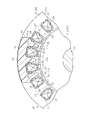
- the side sectional view which shows the electric compressor in embodiment.
- Sectional drawing which shows the attachment state of an attachment member and a stator.
- the perspective view of a cluster block and the periphery of an attachment member The perspective view of the periphery of a cluster block.
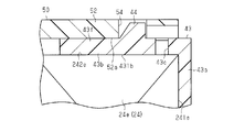
- Sectional drawing which shows the periphery of a convex part and a hole.
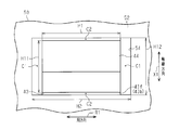
- the top view which shows the periphery of a convex part and a hole.
- the housing 11 of the electric compressor 10 has a bottomed cylindrical discharge housing 12 and a bottomed cylindrical motor housing 13 connected to the discharge housing 12.
- the discharge housing 12 and the motor housing 13 are made of a metal material (for example, made of aluminum).
- the motor housing 13 has a bottom wall 13 e and a side wall 13 a cylindrically extending from the outer peripheral edge of the bottom wall 13 e.
- a suction port 13h is formed on the side wall 13a.
- the suction port 13 h is connected to an external refrigerant circuit (not shown).
- a discharge chamber 12 a is formed in the discharge housing 12. In the discharge housing 12, a discharge port 12h communicating with the discharge chamber 12a is formed.
- the discharge port 12 h is connected to an external refrigerant circuit.
- the rotation shaft 14 is accommodated in the motor housing 13. Further, in the motor housing 13, a compression unit 15 that compresses the refrigerant by rotation of the rotary shaft 14 and an electric motor 20 that rotates the rotary shaft 14 are accommodated.
- the compression unit 15 and the electric motor 20 are arranged side by side in the direction (axial direction) in which the rotation axis L of the rotation shaft 14 extends.
- the electric motor 20 is disposed closer to the bottom wall 13 e of the motor housing 13 than the compression unit 15.
- a shaft support member 16 is provided between the compression unit 15 and the electric motor 20.
- An insertion hole 16 h through which one end of the rotary shaft 14 is inserted is formed in the central portion of the pivot support member 16.
- a bearing 17 a is provided between the insertion hole 16 h and one end of the rotary shaft 14.
- One end of the rotary shaft 14 is rotatably supported by the bearing 16 via a bearing 17 a.
- a cylindrical bearing 18 projects from the bottom wall 13 e of the motor housing 13.
- the other end of the rotary shaft 14 is inserted inside the bearing portion 18.
- a bearing 17 b is provided between the bearing 18 and the other end of the rotating shaft 14.
- the other end of the rotating shaft 14 is rotatably supported by the bearing 18 via a bearing 17 b.
- the compression unit 15 includes a fixed scroll 15 a fixed to the motor housing 13 and a movable scroll 15 b disposed to face the fixed scroll 15 a.
- the fixed scroll 15a and the movable scroll 15b mesh with each other.
- a compression chamber 15c whose volume can be changed is partitioned.
- the refrigerant sucked into the motor housing 13 from the suction port 13h is sucked into the compression chamber 15c by the turning (suction operation) of the movable scroll 15b.
- the refrigerant in the compression chamber 15c is compressed by the turning (discharge operation) of the movable scroll 15b and is discharged to the discharge chamber 12a.
- the refrigerant discharged to the discharge chamber 12a flows out to the external refrigerant circuit through the discharge port 12h, and returns to the inside of the motor housing 13 through the suction port 13h.
- a bottomed cylindrical cover member 19 is attached to the bottom wall 13 e of the motor housing 13.
- a drive circuit 30 for driving the electric motor 20 is accommodated in a space partitioned by the bottom wall 13 e of the motor housing 13 and the cover member 19.
- the compression unit 15, the electric motor 20 and the drive circuit 30 are arranged in this order along the rotation axis L of the rotation shaft 14.
- the electric motor 20 includes a rotor 21 that rotates integrally with the rotating shaft 14, and a stator 22 that surrounds the rotor 21.
- the rotor 21 has a rotor core 21 a fixed to the rotating shaft 14 and a plurality of permanent magnets (not shown) provided on the rotor core 21 a.
- the stator 22 has a cylindrical stator core 23 and a coil 24 wound around the stator core 23.
- the stator core 23 is assembled to the motor housing 13 by being fitted inside the motor housing 13 by shrink fitting.
- the motor housing 13 is heated and expanded to make the inner diameter of the motor housing 13 larger than the outer diameter of the stator core 23, and then the stator core 23 is inserted into the motor housing 13 to a predetermined shrink fit position. Then, the inner circumferential surface of the motor housing 13 is brought into pressure contact with the outer circumferential surface of the stator core 23 by the contraction accompanying the transition of the motor housing 13 to the normal temperature.
- a plurality of teeth 25 are arranged side by side in the circumferential direction of the rotating shaft 14. Slots 26 are formed between the teeth 25 adjacent in the circumferential direction of the rotating shaft 14. The plurality of slots 26 are arranged at equal pitches in the circumferential direction of the rotation shaft 14.
- the insulating sheet 27 is provided to extend along the axial direction of the rotating shaft 14 in the slot 26. Further, both axial ends of the insulating sheet 27 in the axial direction of the rotary shaft 14 project from both end faces 23 e of the stator core 23 located in the axial direction of the rotary shaft 14.
- cuff portions 27 e are formed bent at both axial end portions of the rotary shaft 14 in each insulating sheet 27, and the bent end of each cuff portion 27 e is engaged with each end face 23 e of the stator core 23. It has been stopped. Thus, the axial displacement of the insulating sheet 27 with respect to the stator core 23 in the slot 26 is prevented.
- the coil 24 is wound around the teeth 25 via a cylindrical insulating sheet 27. A portion of the coil 24 annularly protrudes from both end surfaces 23 e of the stator core 23 in the axial direction of the rotating shaft 14 to form a coil end 24 e.
- a part of the coil 24 is drawn out from the coil end 24 e disposed opposite to the bottom wall 13 e of the motor housing 13 as a motor wire 28 in a state of being coated with an insulating film. Specifically, three motor wires 28 are drawn out from the coil end 24 e corresponding to the U-phase, V-phase and W-phase coils 24.
- the gap 29 is a space formed by projecting both end portions in the axial direction of the rotary shaft 14 in the insulating sheet 27 from the end face 23 e of the stator core 23. And, by forming the gap 29, insulation between the end face 23e of the stator core 23 and the coil end 24e is secured.
- the drive circuit 30 is provided with three circuit wires 31 (only one is shown in FIG. 1) corresponding to the motor wires 28 of each phase.
- Three circuit wirings 31 extend from the drive circuit 30 into the motor housing 13 through the bottom wall 13 e of the motor housing 13.
- the cluster block 40 includes a main body 42 that accommodates the conductive member 41.
- a portion of the main body 42 is disposed radially inward of the rotary shaft 14 with respect to the coil end 24 e. That is, a part of the main body 42 and a part of the coil end 24 e are opposed in the radial direction of the rotating shaft 14.
- the main body portion 42 is constituted by three hollow prismatic members, and the three members are integrated in a state of being juxtaposed in the circumferential direction of the rotation shaft 14.
- the main body portion 42 has three first insertion holes 42 a into which the motor wires 28 are inserted, and three second insertion holes 42 b into which the circuit wires 31 are inserted.
- the first insertion hole 42a and the second insertion hole 42b are provided in each of the three members.
- Each first insertion hole 42 a penetrates the partition wall of the main body 42 in the radial direction of the rotary shaft 14.
- Each second insertion hole 42 b is disposed radially inward of the coil end 24 e with respect to the rotary shaft 14 and penetrates the partition wall of the main body 42 in the axial direction of the rotary shaft 14.
- Each motor wire 28 is inserted into each first insertion hole 42 a and connected to each conductive member 41.
- Each circuit wiring 31 is inserted into each second insertion hole 42 b and connected to each conductive member 41. Therefore, each motor wire 28 and each circuit wire 31 are electrically connected via each conductive member 41.
- the electric power controlled by the drive circuit 30 is supplied to the electric motor 20 through the circuit wiring 31, the conductive members 41, and the motor wiring 28, and the electric motor 20 is driven.
- the cluster block 40 is provided with a connecting portion 43.
- the connecting portion 43 is integrally formed with the main body portion 42, but may be fixed to the main body portion 42 after being formed as a separate member from the main body portion 42.
- the connecting portion 43 is continuous with the first connecting portion 43a which is continuous with the main body portion 42 and extends along the outer end portion 241e located in the axial direction of the rotary shaft 14 in the coil end 24e. And a second connecting portion 43b extending along an outer peripheral portion 242e of the end 24e (a portion of the end of the coil end 24e located in the radial direction of the rotating shaft 14 and radially outward of the rotating shaft 14).
- the first connecting portion 43a extends outward in the radial direction of the rotary shaft 14 from the main body 42
- the second connecting portion 43b is on the opposite side of the first connecting portion 43a to the main body 42 side. It extends from the edge toward the end face 23 e of the stator core 23 in the axial direction of the rotary shaft 14.
- the cluster block 40 has a connecting portion extending in the axial direction of the rotating shaft 14.
- first connection portion 43a is flat
- second connection portion 43b is an arc-shaped plate extending in the circumferential direction of the rotation shaft 14.
- the surface 431b of the second coupling portion 43b facing the outer peripheral portion 242e of the coil end 24e is in contact with the outer peripheral portion 242e of the coil end 24e.
- An elastic piece 43f is formed in the second connection portion 43b.
- the elastic piece 43f is formed in the second connection portion 43b by forming the through groove 43c in the second connection portion 43b.
- the elastic piece 43f can be bent with the base end as a base point.
- a projection 44 is provided at the tip of the elastic piece 43f. Therefore, the convex part 44 is provided in the connection part 43.
- the convex portion 44 protrudes outward in the radial direction of the rotation shaft 14 from the tip end portion of the elastic piece 43 f.
- the motor-driven compressor 10 includes an attachment member 50 attached to the stator 22.
- the mounting member 50 has a first extending portion 51 extending along the end face 23 e of the stator core 23.
- the first extending portion 51 includes an extending portion 51a extending in the circumferential direction of the rotating shaft 14 along the end face 23e of the stator core 23, and three projecting from the extending portion 51a in the circumferential direction of the rotating shaft 14 And an insertion protrusion 51b.
- Each insertion protrusion 51b has a tapered shape which becomes thinner as it goes away from the extension 51a.
- the insertion protrusions 51 b are inserted into the gaps 29 from the outer peripheral side of the coil end 24 e in the radial direction of the rotary shaft 14.
- the mounting member 50 is restricted from moving in the circumferential direction of the rotary shaft 14 with respect to the stator 22 by the contact between each insertion projection 51 b and the two insulating sheets 27 adjacent in the circumferential direction of the rotary shaft 14. .
- the mounting member 50 is restricted from moving in the axial direction of the rotary shaft 14 with respect to the stator 22 by the insertion projections 51b, the end face 23e of the stator core 23, and the insertion projections 51b and the coil end 24e.
- the second extending portion 52 is provided with a hole 54 into which the convex portion 44 is inserted.
- the hole 54 is a through hole that penetrates the second extending portion 52.
- the hole 54 is rectangular in plan view.
- the convex portion 44 abuts on the surface 52 a on the second connecting portion 43 b side in the second extending portion 52.
- the elastic piece 43 f bends with the base end as a base point.
- the elastic piece 43f is inserted. With the base end as a base point, the state before bending is restored, and the convex portion 44 is inserted into the hole 54 and locked in the hole 54.
- the connecting portion 43 and the mounting member 50 are connected by the locking of the convex portion 44 and the hole 54. Therefore, the cluster block 40 is attached to the stator 22 via the attachment member 50.
- the insertion direction in which the convex portion 44 is inserted into the hole 54 and the insertion direction in which each circuit wiring 31 is inserted into each second insertion hole 42 b cross each other, not in the same direction.
- the insertion direction in which the convex portion 44 is inserted into the hole 54 is the radial direction of the rotation shaft 14
- the insertion direction in which each circuit wiring 31 is inserted into the second insertion holes 42 b is the rotation shaft 14 in the axial direction.
- the difference between the dimension H1 in the circumferential direction (direction of arrow R1 shown in FIG. 6) of the rotary shaft 14 in the convex portion 44 and the dimension H2 in the circumferential direction of the rotary shaft 14 in the hole 54 is
- the difference between the dimension H11 in the axial direction (the direction of the arrow X1 shown in FIG. 6) of the rotary shaft 14 in the convex portion 44 and the dimension H12 in the axial direction of the rotary shaft 14 in the hole 54 is larger. Therefore, the clearance C1 in the circumferential direction of the rotary shaft 14 is larger than the clearance C2 in the axial direction of the rotary shaft 14 in the clearance between the convex portion 44 and the hole 54.
- the insertion direction in which the convex portion 44 is inserted into the hole 54 crosses the insertion direction in which the circuit wiring 31 is inserted into the second insertion holes 42 b. Therefore, when the circuit wiring 31 is pulled out from the second insertion hole 42 b, the cluster block 40 is less likely to come off the stator 22.
- stator core 23 is assembled to motor housing 13 with cluster block 40 attached to stator 22 if positional displacement of stator core 23 occurs in the circumferential direction of rotary shaft 14 from the aiming position, the position of circuit wiring 31 moves As a result, the circuit wiring 31 can not be inserted into the cluster block 40.
- the clearance C1 in the circumferential direction of the rotation shaft 14 is made larger than the clearance C2 in the axial direction of the rotation shaft 14.
- the connecting portion 43 can move in the circumferential direction of the rotary shaft 14 with respect to the mounting member 50. Therefore, even if positional deviation of the stator core 23 occurs in the circumferential direction of the rotary shaft 14 from the aiming position, It is possible to insert the circuit wiring 31 into the block 40.
- the clearance C2 is smaller than the clearance C1, when the circuit wiring 31 is pulled out from the second insertion hole 42b, the cluster block 40 does not easily come off the stator 22.
- the connecting portion 43 is provided with the convex portion 44 projecting in the radial direction of the rotation shaft 14, and the second extending portion 52 is provided with the hole 54 into which the convex portion 44 is inserted .
- the connecting portion 43 and the mounting member 50 are connected by the projection 44 being engaged with the hole 54. According to this, the insertion direction in which the convex portion 44 is inserted into the hole 54 intersects with the insertion direction in which the circuit wiring 31 is inserted into the second insertion hole 42 b. Therefore, when the circuit wiring 31 is pulled out from the second insertion hole 42 b, the cluster block 40 is unlikely to come off the stator 22.
- the connecting portion 43 is integrally formed with the cluster block 40. According to this, the configuration can be simplified as compared with the case where the connecting portion 43 is separate from the cluster block 40.
- the insertion projection 51b is inserted into the gap 29 formed between the end face 23e of the stator core 23 and the coil end 24e.
- the gap 29 is necessary to ensure insulation between the end face 23e of the stator core 23 and the coil end 24e. Therefore, for example, there is no need to separately form a space for inserting the insertion protrusion 51b into the coil end 24e. Therefore, the cluster block 40 can be attached to the stator 22 through the attachment member 50 by inserting the insertion projection 51b into the gap 29 between the end face 23e of the stator core 23 and the coil end 24e, which is an existing space portion. it can.
- each circuit wiring 31 is inserted into each second insertion hole 42b and each conductive member 41 is inserted.
- the second extending portion 52 may be provided with a protrusion
- the second connecting portion 43b may be provided with a hole into which the protrusion is inserted.
- the point is that a convex portion is provided on one of the second extending portion 52 and the second connection portion 43b, and a hole in which the convex portion is inserted is provided on the other, and the convex portion is locked in the hole.
- the connecting portion 43 may be connected to the mounting member 50.
- the protrusion 44 may protrude from the tip of the elastic piece 43 f in the direction oblique to the radial direction of the rotation shaft 14 and radially outward of the rotation shaft 14.
- the insertion direction of the convex portion 44 into the hole 54 may be a direction oblique to the radial direction of the rotary shaft 14 and a radial outer direction of the rotary shaft 14. The point is that the insertion direction of the convex portion 44 with respect to the hole portion 54 may be a direction intersecting the insertion direction of the circuit wiring 31 with respect to the second insertion hole 42 b.
- the second connecting portion 43 b is disposed so as to overlap the second extending portion 52 in the radial direction of the rotating shaft 14 outside the second extending portion 52 in the radial direction of the rotating shaft 14. It is also good. (Circle) in embodiment, the connection part 43 may not have the 1st connection part 43a, and the main-body part 42 may be following the 2nd connection part 43b. And each 2nd insertion hole 42b is not arrange
- the attachment member attached to the stator 22 may be, for example, an existing member constituting the stator 22, such as a coil bobbin.
- the connecting portion 43 may be a separate member from the cluster block 40.
- the hole 54 may be a recess not penetrating the second extending portion 52.
- the connecting portion 43 and the second extending portion 52 of the mounting member 50 may be disposed radially inward of the rotary shaft 14 with respect to the coil end 24e.
- the number of the insertion protrusions 51b is not particularly limited.
- the stator core 23 may be assembled to the inside of the motor housing 13 by a method other than shrink fitting.
- the compression unit 15, the electric motor 20, and the drive circuit 30 may not be arranged along the rotation axis L of the rotation shaft 14 in this order.
- the cover member 19 may be attached to the side wall 13 a of the motor housing 13, and the drive circuit 30 may be accommodated in the space defined by the side wall 13 a of the motor housing 13 and the cover member 19.
- the compression unit 15 is not limited to the type configured by the fixed scroll 15a and the movable scroll 15b, and may be changed to, for example, a piston type or a vane type.
- the electric compressor 10 may not be used for a vehicle air conditioner, and may be used for other air conditioners.
- the motor-driven fluid machine is embodied in the motor-driven compressor 10 for compressing the refrigerant.
- the present invention is not limited thereto.
- the motor-driven fluid machine is embodied in a pump used for pumping fluid. May be
- the electric fluid machine is an electric compressor that compresses a refrigerant.
Abstract
This electrically driven fluid machine comprises an insulative hollow cluster block accommodated within a housing. The cluster block is electrically connected to motor wiring extended from the coils of an electric motor, and also to circuit wiring provided in a drive circuit. A mounting member having an extension section extending in the axial direction of a rotating shaft is mounted to the stator of the electric motor. The cluster block comprises: a connection section extending in the axial direction of the rotating shaft; a first insertion hole which extends through a partition wall of the cluster block and into which the motor wiring is inserted; and a second insertion hole which extends through a partition wall in the axial direction of the rotating shaft and into which the circuit wiring is inserted. Either the extension section or the connection section is provided with a protrusion protruding in the radial direction of the rotating shaft, and the other of the extension section and the connection section is provided with a hole into which the protrusion is inserted. The engagement of the protrusion with the hole connects the connection section and the mounting member.
Description
本発明は、回転軸を回転させる電動モータと、電動モータを駆動させる駆動回路とを有する電動式流体機械に関する。
The present invention relates to an electric fluid machine having an electric motor for rotating a rotating shaft and a drive circuit for driving the electric motor.
電動圧縮機は、回転軸が回転することにより駆動して冷媒を圧縮する圧縮部を備えている。電動圧縮機のハウジングは筒状であり、圧縮部及び電動モータを収容している。電動モータは、ハウジングの内周面に固定されるステータと、回転軸と一体的に回転するロータとを備えている。ステータは、筒状のステータコアと、ステータコアに捲回されたコイルとを有している。ステータコアにおける回転軸の軸線方向に位置する端面からは、環状のコイルエンドが突出している。コイルエンドからはモータ配線が引き出されている。また、駆動回路には、モータ配線に電気的に接続される回路配線が設けられている。
The electric compressor includes a compression unit that is driven by the rotation of the rotation shaft to compress the refrigerant. The housing of the electric compressor is cylindrical and accommodates the compression unit and the electric motor. The electric motor includes a stator fixed to the inner peripheral surface of the housing, and a rotor that rotates integrally with the rotation shaft. The stator has a cylindrical stator core and a coil wound around the stator core. An annular coil end projects from an end face of the stator core located in the axial direction of the rotation shaft. Motor wiring is drawn out from the coil end. In addition, the drive circuit is provided with circuit wiring electrically connected to the motor wiring.
ハウジング内には、モータ配線と回路配線とを電気的に接続する導電部材を収容する絶縁性のクラスタブロックが配置されている。クラスタブロックは、モータ配線が挿入される第1挿入孔と、回路配線が挿入される第2挿入孔とを有する。モータ配線と回路配線とが導電部材を介して電気的に接続されることで、駆動回路から回路配線、導電部材及びモータ配線を介して電動モータに電力が供給されて電動モータが駆動し、電動モータの駆動に伴う回転軸の回転によって、圧縮部が駆動して冷媒が圧縮部により圧縮される。
In the housing, an insulating cluster block is disposed which accommodates a conductive member for electrically connecting the motor wiring and the circuit wiring. The cluster block has a first insertion hole into which the motor wiring is inserted and a second insertion hole into which the circuit wiring is inserted. By electrically connecting the motor wiring and the circuit wiring through the conductive member, electric power is supplied from the drive circuit to the electric motor through the circuit wiring, the conductive member and the motor wiring, and the electric motor is driven. The compression unit is driven by the rotation of the rotation shaft accompanying the drive of the motor, and the refrigerant is compressed by the compression unit.
例えば特許文献1に開示されている電動圧縮機においては、ステータのボビンにステータコイルエンドカバーが取り付けられている。ステータコイルエンドカバーには、2本の爪部が一体形成されている。また、クラスタブロックには、二つの取付孔が設けられている。そして、各爪部が、各取付孔に挿入されて、各爪部が各取付孔に嵌合されることにより、クラスタブロックがステータコイルエンドカバーを介してステータに取り付けられている。
For example, in the electric compressor disclosed in Patent Document 1, a stator coil end cover is attached to a bobbin of a stator. Two claws are integrally formed on the stator coil end cover. Further, two mounting holes are provided in the cluster block. Then, each claw portion is inserted into each mounting hole, and each claw portion is fitted to each mounting hole, whereby the cluster block is mounted to the stator via the stator coil end cover.
ところで、特許文献1の電動圧縮機においては、各爪部を各取付孔へ挿入する挿入方向と、ハーメチック端子(回路配線)をクラスタブロックの端子接続口(第2挿入孔)へ挿入する挿入方向とが同一方向となっている。このような場合、ハーメチック端子を端子接続口から引き抜こうとすると、各爪部が各取付孔から外れてしまい、クラスタブロックがステータから脱落してしまう虞がある。
By the way, in the motor-driven compressor of Patent Document 1, the insertion direction in which the claws are inserted into the mounting holes and the insertion direction in which the hermetic terminals (circuit wiring) are inserted into the terminal connection ports (second insertion holes) of the cluster block. And are in the same direction. In such a case, when it is attempted to pull out the hermetic terminal from the terminal connection port, there is a possibility that the respective claws may come off the respective mounting holes, and the cluster block may come off the stator.
本発明は、上記課題を解決するためになされたものであって、その目的は、回路配線をクラスタブロックから引き抜いた際に、クラスタブロックがステータから脱落しにくい電動式流体機械を提供することにある。
The present invention has been made to solve the above-mentioned problems, and it is an object of the present invention to provide an electric fluid machine in which a cluster block is less likely to come off the stator when circuit wiring is pulled out of the cluster block. is there.
上記課題を解決する電動式流体機械は、筒状のハウジングと、前記ハウジング内に収容される回転軸と、前記ハウジング内に収容され、前記回転軸を回転させる電動モータであって、ステータコアと当該ステータコアに捲回されたコイルとを有するステータを備える電動モータと、前記電動モータを駆動させる駆動回路と、前記コイルから引き出されるモータ配線と、前記駆動回路に設けられる回路配線と、前記ハウジング内に収容されるとともに、前記モータ配線及び前記回路配線と電気的に接続される導電部材を収容する絶縁性でかつ中空状のクラスタブロックと、を備える電動式流体機械であって、前記回転軸の軸線方向に延設する延設部を有し、前記ステータに取り付けられる取付部材を備え、前記クラスタブロックは、前記回転軸の軸線方向に延設する連結部と、前記クラスタブロックの隔壁を貫通し、前記モータ配線が挿入される第1挿入孔と、前記クラスタブロックの隔壁を前記回転軸の軸線方向に貫通し、前記回路配線が挿入される第2挿入孔と、を備え、前記延設部及び前記連結部の一方には、前記回転軸の径方向に突出する凸部が設けられるとともに、他方には前記凸部が挿入される孔部が設けられ、前記凸部が前記孔部に係止されることにより前記連結部と前記取付部材とが連結される。
An electric fluid machine to solve the above problems is a cylindrical housing, a rotary shaft housed in the housing, and an electric motor housed in the housing and rotating the rotary shaft, the stator core and the like An electric motor including a stator having a coil wound around a stator core, a drive circuit for driving the electric motor, a motor wiring drawn from the coil, a circuit wiring provided in the drive circuit, and the housing An electrically-conductive fluid machine including: an insulating, hollow cluster block that accommodates and accommodates a conductive member electrically connected to the motor wiring and the circuit wiring, wherein the axial line of the rotation shaft And a mounting member attached to the stator, and the cluster block includes the rotation member. A connecting portion extending in the axial direction, a partition wall of the cluster block, and a first insertion hole into which the motor wiring is inserted; and a partition wall of the cluster block in the axial direction of the rotation shaft; A second insertion hole into which a circuit wiring is inserted, and one of the extension portion and the connection portion is provided with a convex portion protruding in the radial direction of the rotation shaft, and the other is provided with the convex portion There is provided a hole into which the connector is inserted, and the connecting portion and the mounting member are connected by locking the convex portion in the hole.
これによれば、凸部を孔部に挿入する挿入方向と、回路配線を第2挿入孔に挿入する挿入方向とが、交差している。よって、回路配線を第2挿入孔から引き抜いた際に、クラスタブロックがステータから脱落しにくい。
According to this, the insertion direction in which the convex portion is inserted into the hole crosses the insertion direction in which the circuit wiring is inserted into the second insertion hole. Therefore, when the circuit wiring is pulled out from the second insertion hole, the cluster block is unlikely to come off the stator.
上記電動式流体機械において、前記孔部における前記回転軸の周方向の寸法と前記凸部における前記回転軸の周方向の寸法との差は、前記孔部における前記回転軸の軸線方向の寸法と前記凸部における前記回転軸の軸線方向の寸法との差よりも大きいことが好ましい。
In the above-mentioned electric fluid machine, the difference between the circumferential dimension of the rotary shaft in the hole and the circumferential dimension of the rotary shaft in the convex portion is the axial dimension of the rotary shaft in the hole It is preferable that the difference is larger than the difference between the dimension of the convex portion in the axial direction of the rotation axis.
これによれば、連結部は、取付部材に対して、回転軸の周方向に移動可能になるため、ステータコアのねらい位置から回転軸の周方向にステータコアの位置ズレが発生しても、クラスタブロックに回路配線を挿入することが可能となる。さらに、回路配線を第2挿入孔から引き抜いた際に、クラスタブロックがステータから脱落しにくくなる。
According to this, since the connecting portion can move in the circumferential direction of the rotating shaft with respect to the mounting member, the cluster block can be moved even if positional deviation of the stator core occurs in the circumferential direction of the rotating shaft from the position aimed by the stator core. Circuit wiring can be inserted into the Furthermore, when the circuit wiring is pulled out from the second insertion hole, the cluster block is less likely to come off the stator.
上記電動式流体機械において、前記連結部は、前記クラスタブロックに一体形成されていることが好ましい。これによれば、連結部がクラスタブロックとは別体である場合に比べて、構成を簡素化することができる。
In the motor-driven fluid machine, preferably, the connection portion is integrally formed with the cluster block. According to this, the configuration can be simplified as compared with the case where the connecting part is separate from the cluster block.
上記電動式流体機械において、前記連結部は、前記延設部と前記コイルとの間に挟み込まれていることが好ましい。これによれば、クラスタブロックにおけるステータに対する取り付けを強固なものとすることができる。
In the motor-driven fluid machine, it is preferable that the connection portion be sandwiched between the extension portion and the coil. According to this, the attachment to the stator in the cluster block can be made strong.
この発明によれば、回路配線をクラスタブロックから引き抜いた際に、クラスタブロックがステータから脱落しにくい。
According to the present invention, when the circuit wiring is pulled out of the cluster block, the cluster block does not easily come off the stator.
以下、電動式流体機械を電動圧縮機に具体化した一実施形態を図1~図6にしたがって説明する。なお、本実施形態の電動圧縮機は車両空調装置に用いられる。
図1に示すように、電動圧縮機10のハウジング11は、有底筒状の吐出ハウジング12と、吐出ハウジング12に連結される有底筒状のモータハウジング13とを有している。吐出ハウジング12及びモータハウジング13は金属材料製(例えばアルミニウム製)である。モータハウジング13は、底壁13eと、底壁13eの外周縁から筒状に延設する側壁13aとを有している。側壁13aには、吸入ポート13hが形成されている。吸入ポート13hは、図示しない外部冷媒回路に接続されている。吐出ハウジング12内には、吐出室12aが形成されている。吐出ハウジング12には、吐出室12aに連通する吐出ポート12hが形成されている。吐出ポート12hは、外部冷媒回路に接続されている。 An embodiment in which the motor-driven fluid machine is embodied as a motor-driven compressor will be described below with reference to FIGS. The electric compressor of the present embodiment is used for a vehicle air conditioner.
As shown in FIG. 1, the housing 11 of theelectric compressor 10 has a bottomed cylindrical discharge housing 12 and a bottomed cylindrical motor housing 13 connected to the discharge housing 12. The discharge housing 12 and the motor housing 13 are made of a metal material (for example, made of aluminum). The motor housing 13 has a bottom wall 13 e and a side wall 13 a cylindrically extending from the outer peripheral edge of the bottom wall 13 e. A suction port 13h is formed on the side wall 13a. The suction port 13 h is connected to an external refrigerant circuit (not shown). A discharge chamber 12 a is formed in the discharge housing 12. In the discharge housing 12, a discharge port 12h communicating with the discharge chamber 12a is formed. The discharge port 12 h is connected to an external refrigerant circuit.
図1に示すように、電動圧縮機10のハウジング11は、有底筒状の吐出ハウジング12と、吐出ハウジング12に連結される有底筒状のモータハウジング13とを有している。吐出ハウジング12及びモータハウジング13は金属材料製(例えばアルミニウム製)である。モータハウジング13は、底壁13eと、底壁13eの外周縁から筒状に延設する側壁13aとを有している。側壁13aには、吸入ポート13hが形成されている。吸入ポート13hは、図示しない外部冷媒回路に接続されている。吐出ハウジング12内には、吐出室12aが形成されている。吐出ハウジング12には、吐出室12aに連通する吐出ポート12hが形成されている。吐出ポート12hは、外部冷媒回路に接続されている。 An embodiment in which the motor-driven fluid machine is embodied as a motor-driven compressor will be described below with reference to FIGS. The electric compressor of the present embodiment is used for a vehicle air conditioner.
As shown in FIG. 1, the housing 11 of the
モータハウジング13内には、回転軸14が収容されている。また、モータハウジング13内には、回転軸14が回転することにより冷媒を圧縮する圧縮部15と、回転軸14を回転させる電動モータ20とが収容されている。圧縮部15及び電動モータ20は、回転軸14の回転軸線Lが延びる方向(軸線方向)に並んで配置されている。電動モータ20は、圧縮部15よりもモータハウジング13の底壁13e側に配置されている。
The rotation shaft 14 is accommodated in the motor housing 13. Further, in the motor housing 13, a compression unit 15 that compresses the refrigerant by rotation of the rotary shaft 14 and an electric motor 20 that rotates the rotary shaft 14 are accommodated. The compression unit 15 and the electric motor 20 are arranged side by side in the direction (axial direction) in which the rotation axis L of the rotation shaft 14 extends. The electric motor 20 is disposed closer to the bottom wall 13 e of the motor housing 13 than the compression unit 15.
モータハウジング13内において、圧縮部15と電動モータ20との間には軸支部材16が設けられている。軸支部材16の中央部には、回転軸14の一端部が挿通される挿通孔16hが形成されている。挿通孔16hと回転軸14の一端部との間にはベアリング17aが設けられている。回転軸14の一端部は、ベアリング17aを介して軸支部材16に回転可能に支持されている。
In the motor housing 13, a shaft support member 16 is provided between the compression unit 15 and the electric motor 20. An insertion hole 16 h through which one end of the rotary shaft 14 is inserted is formed in the central portion of the pivot support member 16. A bearing 17 a is provided between the insertion hole 16 h and one end of the rotary shaft 14. One end of the rotary shaft 14 is rotatably supported by the bearing 16 via a bearing 17 a.
モータハウジング13の底壁13eには、筒状の軸受部18が突設されている。軸受部18の内側には回転軸14の他端が挿入されている。軸受部18と回転軸14の他端との間にはベアリング17bが設けられている。回転軸14の他端は、ベアリング17bを介して軸受部18に回転可能に支持されている。
A cylindrical bearing 18 projects from the bottom wall 13 e of the motor housing 13. The other end of the rotary shaft 14 is inserted inside the bearing portion 18. A bearing 17 b is provided between the bearing 18 and the other end of the rotating shaft 14. The other end of the rotating shaft 14 is rotatably supported by the bearing 18 via a bearing 17 b.
圧縮部15は、モータハウジング13に固定された固定スクロール15aと、固定スクロール15aに対向配置された可動スクロール15bとを有している。固定スクロール15aと可動スクロール15bとは互いに噛み合っている。そして、固定スクロール15aと可動スクロール15bとの間には容積変更可能な圧縮室15cが区画されている。
The compression unit 15 includes a fixed scroll 15 a fixed to the motor housing 13 and a movable scroll 15 b disposed to face the fixed scroll 15 a. The fixed scroll 15a and the movable scroll 15b mesh with each other. And, between the fixed scroll 15a and the movable scroll 15b, a compression chamber 15c whose volume can be changed is partitioned.
吸入ポート13hからモータハウジング13内に吸入された冷媒は、可動スクロール15bの旋回(吸入動作)によって、圧縮室15cに吸入される。圧縮室15c内の冷媒は、可動スクロール15bの旋回(吐出動作)によって圧縮されて、吐出室12aに吐出される。吐出室12aに吐出された冷媒は、吐出ポート12hを介して外部冷媒回路へ流出し、吸入ポート13hを介してモータハウジング13内に還流する。
The refrigerant sucked into the motor housing 13 from the suction port 13h is sucked into the compression chamber 15c by the turning (suction operation) of the movable scroll 15b. The refrigerant in the compression chamber 15c is compressed by the turning (discharge operation) of the movable scroll 15b and is discharged to the discharge chamber 12a. The refrigerant discharged to the discharge chamber 12a flows out to the external refrigerant circuit through the discharge port 12h, and returns to the inside of the motor housing 13 through the suction port 13h.
モータハウジング13の底壁13eには、有底筒状のカバー部材19が取り付けられている。モータハウジング13の底壁13eとカバー部材19とで区画された空間には、電動モータ20を駆動させる駆動回路30が収容されている。圧縮部15、電動モータ20及び駆動回路30は、この順序で、回転軸14の回転軸線Lに沿って並んで配置されている。
A bottomed cylindrical cover member 19 is attached to the bottom wall 13 e of the motor housing 13. In a space partitioned by the bottom wall 13 e of the motor housing 13 and the cover member 19, a drive circuit 30 for driving the electric motor 20 is accommodated. The compression unit 15, the electric motor 20 and the drive circuit 30 are arranged in this order along the rotation axis L of the rotation shaft 14.
電動モータ20は、回転軸14と一体的に回転するロータ21と、ロータ21を取り囲むステータ22とを備えている。ロータ21は、回転軸14に止着されたロータコア21aと、ロータコア21aに設けられた複数の永久磁石(図示せず)とを有している。ステータ22は、筒状のステータコア23と、ステータコア23に捲回されたコイル24とを有している。
The electric motor 20 includes a rotor 21 that rotates integrally with the rotating shaft 14, and a stator 22 that surrounds the rotor 21. The rotor 21 has a rotor core 21 a fixed to the rotating shaft 14 and a plurality of permanent magnets (not shown) provided on the rotor core 21 a. The stator 22 has a cylindrical stator core 23 and a coil 24 wound around the stator core 23.
ステータコア23は、焼き嵌めによってモータハウジング13の内側に嵌め込まれることによりモータハウジング13に組み付けられている。この焼き嵌めは、モータハウジング13を加熱膨張させてモータハウジング13の内径をステータコア23の外径よりも大きくした後、モータハウジング13内にステータコア23を予め定められた焼き嵌め位置まで挿入する。そして、モータハウジング13の常温への移行に伴う収縮によってモータハウジング13の内周面をステータコア23の外周面に圧接させることにより行われる。
The stator core 23 is assembled to the motor housing 13 by being fitted inside the motor housing 13 by shrink fitting. In this shrink fitting, the motor housing 13 is heated and expanded to make the inner diameter of the motor housing 13 larger than the outer diameter of the stator core 23, and then the stator core 23 is inserted into the motor housing 13 to a predetermined shrink fit position. Then, the inner circumferential surface of the motor housing 13 is brought into pressure contact with the outer circumferential surface of the stator core 23 by the contraction accompanying the transition of the motor housing 13 to the normal temperature.
図2に示すように、ステータコア23には、複数のティース25が回転軸14の周方向に並んで配列されている。回転軸14の周方向で隣り合うティース25の間にはスロット26が形成されている。複数のスロット26は、回転軸14の周方向に等ピッチで配列されている。絶縁シート27は、スロット26内において回転軸14の軸線方向に沿って延びるように設けられている。そして、絶縁シート27における回転軸14の軸線方向の両端部は、ステータコア23における回転軸14の軸線方向に位置する両端面23eから突出している。
As shown in FIG. 2, in the stator core 23, a plurality of teeth 25 are arranged side by side in the circumferential direction of the rotating shaft 14. Slots 26 are formed between the teeth 25 adjacent in the circumferential direction of the rotating shaft 14. The plurality of slots 26 are arranged at equal pitches in the circumferential direction of the rotation shaft 14. The insulating sheet 27 is provided to extend along the axial direction of the rotating shaft 14 in the slot 26. Further, both axial ends of the insulating sheet 27 in the axial direction of the rotary shaft 14 project from both end faces 23 e of the stator core 23 located in the axial direction of the rotary shaft 14.
図1に示すように、各絶縁シート27における回転軸14の軸線方向の両端部には、カフス部27eが折り曲げ形成されており、各カフス部27eの折り曲げ先端はステータコア23の各端面23eに係止されている。これにより、スロット26内でのステータコア23に対する絶縁シート27の軸方向へのずれが防止されている。
As shown in FIG. 1, cuff portions 27 e are formed bent at both axial end portions of the rotary shaft 14 in each insulating sheet 27, and the bent end of each cuff portion 27 e is engaged with each end face 23 e of the stator core 23. It has been stopped. Thus, the axial displacement of the insulating sheet 27 with respect to the stator core 23 in the slot 26 is prevented.
コイル24は、筒状の絶縁シート27を介してティース25に捲回されている。
コイル24の一部分は、ステータコア23の両端面23eから回転軸14の軸線方向に環状に突出し、コイルエンド24eを形成する。 Thecoil 24 is wound around the teeth 25 via a cylindrical insulating sheet 27.
A portion of thecoil 24 annularly protrudes from both end surfaces 23 e of the stator core 23 in the axial direction of the rotating shaft 14 to form a coil end 24 e.
コイル24の一部分は、ステータコア23の両端面23eから回転軸14の軸線方向に環状に突出し、コイルエンド24eを形成する。 The
A portion of the
モータハウジング13の底壁13eに対向配置されるコイルエンド24eからは、コイル24の一部が、絶縁被膜によって被膜された状態でモータ配線28として引き出されている。具体的には、コイルエンド24eからは、U相、V相及びW相のコイル24に対応して3つのモータ配線28が引き出されている。
A part of the coil 24 is drawn out from the coil end 24 e disposed opposite to the bottom wall 13 e of the motor housing 13 as a motor wire 28 in a state of being coated with an insulating film. Specifically, three motor wires 28 are drawn out from the coil end 24 e corresponding to the U-phase, V-phase and W-phase coils 24.
図1及び図2に示すように、回転軸14の軸線方向において、ステータコア23の端面23eとコイルエンド24eとの間であり、且つ、ステータコア23の周方向において、隣り合う絶縁シート27同士の間には隙間29が形成されている。この隙間29は、絶縁シート27における回転軸14の軸線方向の両端部が、ステータコア23の端面23eから突出していることにより形成された空間部である。そして、この隙間29が形成されることにより、ステータコア23の端面23eとコイルエンド24eとの間の絶縁が確保されている。
As shown in FIGS. 1 and 2, in the axial direction of the rotary shaft 14, between the end face 23e of the stator core 23 and the coil end 24e, and in the circumferential direction of the stator core 23, between adjacent insulating sheets 27. A clearance 29 is formed in the. The gap 29 is a space formed by projecting both end portions in the axial direction of the rotary shaft 14 in the insulating sheet 27 from the end face 23 e of the stator core 23. And, by forming the gap 29, insulation between the end face 23e of the stator core 23 and the coil end 24e is secured.
図1に示すように、モータハウジング13の底壁13eに対向配置されるコイルエンド24eの内側には、軸受部18の一部が入り込んでいる。つまり、コイルエンド24eの一部分と軸受部18の一部分とは、回転軸14の径方向に対向している。
As shown in FIG. 1, a part of the bearing portion 18 intrudes into the inside of the coil end 24 e disposed opposite to the bottom wall 13 e of the motor housing 13. That is, a portion of the coil end 24 e and a portion of the bearing portion 18 are opposed in the radial direction of the rotating shaft 14.
図1に示すように、駆動回路30には、各相のモータ配線28に対応して3つの回路配線31(図1では1つのみ図示)が設けられている。3つの回路配線31は、駆動回路30からモータハウジング13の底壁13eを貫通してモータハウジング13内に延びている。
As shown in FIG. 1, the drive circuit 30 is provided with three circuit wires 31 (only one is shown in FIG. 1) corresponding to the motor wires 28 of each phase. Three circuit wirings 31 extend from the drive circuit 30 into the motor housing 13 through the bottom wall 13 e of the motor housing 13.
モータハウジング13内には、樹脂製である絶縁性のクラスタブロック40が収容されている。クラスタブロック40内には、U相、V相及びW相に対応して3つの導電部材41(図1では1つのみ図示)が収容されている。
In the motor housing 13, an insulating cluster block 40 made of resin is accommodated. In the cluster block 40, three conductive members 41 (only one is shown in FIG. 1) are accommodated corresponding to the U phase, the V phase and the W phase.
クラスタブロック40は、導電部材41を収容する本体部42を備えている。本体部42の一部分は、コイルエンド24eよりも回転軸14の径方向内側に配置されている。つまり、本体部42の一部分とコイルエンド24eの一部分とは、回転軸14の径方向に対向している。
The cluster block 40 includes a main body 42 that accommodates the conductive member 41. A portion of the main body 42 is disposed radially inward of the rotary shaft 14 with respect to the coil end 24 e. That is, a part of the main body 42 and a part of the coil end 24 e are opposed in the radial direction of the rotating shaft 14.
本体部42は、中空角柱状の3つの部材から構成され、3つの部材が回転軸14の周方向に並設された状態で一体化されている。
本体部42は、各モータ配線28が挿入される3つの第1挿入孔42aと、各回路配線31が挿入される3つの第2挿入孔42bとを有する。第1挿入孔42a及び第2挿入孔42bは、3つの部材各々に設けられている。 Themain body portion 42 is constituted by three hollow prismatic members, and the three members are integrated in a state of being juxtaposed in the circumferential direction of the rotation shaft 14.
Themain body portion 42 has three first insertion holes 42 a into which the motor wires 28 are inserted, and three second insertion holes 42 b into which the circuit wires 31 are inserted. The first insertion hole 42a and the second insertion hole 42b are provided in each of the three members.
本体部42は、各モータ配線28が挿入される3つの第1挿入孔42aと、各回路配線31が挿入される3つの第2挿入孔42bとを有する。第1挿入孔42a及び第2挿入孔42bは、3つの部材各々に設けられている。 The
The
各第1挿入孔42aは、本体部42の隔壁を回転軸14の径方向に貫通している。
各第2挿入孔42bは、コイルエンド24eよりも回転軸14の径方向内側に配置されるとともに、本体部42の隔壁を回転軸14の軸線方向に貫通している。 Eachfirst insertion hole 42 a penetrates the partition wall of the main body 42 in the radial direction of the rotary shaft 14.
Eachsecond insertion hole 42 b is disposed radially inward of the coil end 24 e with respect to the rotary shaft 14 and penetrates the partition wall of the main body 42 in the axial direction of the rotary shaft 14.
各第2挿入孔42bは、コイルエンド24eよりも回転軸14の径方向内側に配置されるとともに、本体部42の隔壁を回転軸14の軸線方向に貫通している。 Each
Each
各モータ配線28は、各第1挿入孔42aに挿入されて各導電部材41に接続される。
各回路配線31は、各第2挿入孔42bに挿入されて各導電部材41に接続される。
したがって、各モータ配線28と各回路配線31とが各導電部材41を介して電気的に接続される。これにより、駆動回路30によって制御された電力は、各回路配線31、各導電部材41及び各モータ配線28を介して電動モータ20に供給され、電動モータ20が駆動する。 Eachmotor wire 28 is inserted into each first insertion hole 42 a and connected to each conductive member 41.
Eachcircuit wiring 31 is inserted into each second insertion hole 42 b and connected to each conductive member 41.
Therefore, eachmotor wire 28 and each circuit wire 31 are electrically connected via each conductive member 41. Thus, the electric power controlled by the drive circuit 30 is supplied to the electric motor 20 through the circuit wiring 31, the conductive members 41, and the motor wiring 28, and the electric motor 20 is driven.
各回路配線31は、各第2挿入孔42bに挿入されて各導電部材41に接続される。
したがって、各モータ配線28と各回路配線31とが各導電部材41を介して電気的に接続される。これにより、駆動回路30によって制御された電力は、各回路配線31、各導電部材41及び各モータ配線28を介して電動モータ20に供給され、電動モータ20が駆動する。 Each
Each
Therefore, each
図4に示すように、クラスタブロック40には、連結部43が設けられている。本実施形態では、連結部43は、本体部42と一体形成されているが、本体部42とは別部材で形成した後、本体部42に固定されるようにしてもよい。
As shown in FIG. 4, the cluster block 40 is provided with a connecting portion 43. In the present embodiment, the connecting portion 43 is integrally formed with the main body portion 42, but may be fixed to the main body portion 42 after being formed as a separate member from the main body portion 42.
連結部43は、本体部42に連続するとともにコイルエンド24eにおける回転軸14の軸線方向に位置する外側端部241eに沿って延びる第1連結部43aと、第1連結部43aに連続するとともにコイルエンド24eの外周部242e(コイルエンド24eにおける回転軸14の径方向に位置する端部のうち、回転軸14の径方向外側の部分)に沿って延びる第2連結部43bとを有する。言い換えると、第1連結部43aは、本体部42から回転軸14の径方向外側に向かって延設し、第2連結部43bは、第1連結部43aの本体部42側とは反対側の縁部から回転軸14の軸線方向にステータコア23の端面23eに向かって延設する。よって、クラスタブロック40は、回転軸14の軸線方向に延設する連結部を有する。
The connecting portion 43 is continuous with the first connecting portion 43a which is continuous with the main body portion 42 and extends along the outer end portion 241e located in the axial direction of the rotary shaft 14 in the coil end 24e. And a second connecting portion 43b extending along an outer peripheral portion 242e of the end 24e (a portion of the end of the coil end 24e located in the radial direction of the rotating shaft 14 and radially outward of the rotating shaft 14). In other words, the first connecting portion 43a extends outward in the radial direction of the rotary shaft 14 from the main body 42, and the second connecting portion 43b is on the opposite side of the first connecting portion 43a to the main body 42 side. It extends from the edge toward the end face 23 e of the stator core 23 in the axial direction of the rotary shaft 14. Thus, the cluster block 40 has a connecting portion extending in the axial direction of the rotating shaft 14.
なお、本実施形態では、第1連結部43aは平板状であり、第2連結部43bは回転軸14の周方向に沿って延びる弧状に湾曲した板状である。本実施形態では、第2連結部43bにおけるコイルエンド24eの外周部242eと対向する面431bは、コイルエンド24eの外周部242eに接触している。
In the present embodiment, the first connection portion 43a is flat, and the second connection portion 43b is an arc-shaped plate extending in the circumferential direction of the rotation shaft 14. In the present embodiment, the surface 431b of the second coupling portion 43b facing the outer peripheral portion 242e of the coil end 24e is in contact with the outer peripheral portion 242e of the coil end 24e.
第2連結部43bには、弾性片43fが形成されている。弾性片43fは、第2連結部43bに貫通溝43cを形成することにより、第2連結部43bに形成されている。弾性片43fは、基端を基点として撓むことが可能になっている。弾性片43fの先端部には、凸部44が突設されている。よって、連結部43には、凸部44が設けられている。凸部44は、弾性片43fの先端部から回転軸14の径方向外側に向けて突出している。
An elastic piece 43f is formed in the second connection portion 43b. The elastic piece 43f is formed in the second connection portion 43b by forming the through groove 43c in the second connection portion 43b. The elastic piece 43f can be bent with the base end as a base point. At the tip of the elastic piece 43f, a projection 44 is provided. Therefore, the convex part 44 is provided in the connection part 43. The convex portion 44 protrudes outward in the radial direction of the rotation shaft 14 from the tip end portion of the elastic piece 43 f.
図3に示すように、電動圧縮機10は、ステータ22に取り付けられる取付部材50を備えている。
図2及び図3に示すように、取付部材50は、ステータコア23の端面23eに沿って延びる第1延設部51を有する。第1延設部51は、ステータコア23の端面23eに沿って回転軸14の周方向に延びる延在部51aと、延在部51aから回転軸14の周方向に間隔をおいて突出する3つの挿入突片51bとを有する。各挿入突片51bは、延在部51aから離れるにつれて細くなる先細形状である。 As shown in FIG. 3, the motor-drivencompressor 10 includes an attachment member 50 attached to the stator 22.
As shown in FIGS. 2 and 3, the mountingmember 50 has a first extending portion 51 extending along the end face 23 e of the stator core 23. The first extending portion 51 includes an extending portion 51a extending in the circumferential direction of the rotating shaft 14 along the end face 23e of the stator core 23, and three projecting from the extending portion 51a in the circumferential direction of the rotating shaft 14 And an insertion protrusion 51b. Each insertion protrusion 51b has a tapered shape which becomes thinner as it goes away from the extension 51a.
図2及び図3に示すように、取付部材50は、ステータコア23の端面23eに沿って延びる第1延設部51を有する。第1延設部51は、ステータコア23の端面23eに沿って回転軸14の周方向に延びる延在部51aと、延在部51aから回転軸14の周方向に間隔をおいて突出する3つの挿入突片51bとを有する。各挿入突片51bは、延在部51aから離れるにつれて細くなる先細形状である。 As shown in FIG. 3, the motor-driven
As shown in FIGS. 2 and 3, the mounting
各挿入突片51bは、回転軸14の径方向においてコイルエンド24eの外周側から各隙間29に挿入されている。そして、取付部材50は、各挿入突片51bと、回転軸14の周方向で隣り合う二つの絶縁シート27との接触により、ステータ22に対する回転軸14の周方向への移動が規制されている。また、取付部材50は、各挿入突片51bとステータコア23の端面23e、及び各挿入突片51bとコイルエンド24eにより、ステータ22に対する回転軸14の軸線方向への移動が規制される。
The insertion protrusions 51 b are inserted into the gaps 29 from the outer peripheral side of the coil end 24 e in the radial direction of the rotary shaft 14. The mounting member 50 is restricted from moving in the circumferential direction of the rotary shaft 14 with respect to the stator 22 by the contact between each insertion projection 51 b and the two insulating sheets 27 adjacent in the circumferential direction of the rotary shaft 14. . The mounting member 50 is restricted from moving in the axial direction of the rotary shaft 14 with respect to the stator 22 by the insertion projections 51b, the end face 23e of the stator core 23, and the insertion projections 51b and the coil end 24e.
よって、取付部材50は、ステータ22に取り付けられているといえる。
図3に示すように、取付部材50は、第1延設部51に連続するとともに連結部43が取り付けられる第2延設部52を有する。第2延設部52は、延在部51aにおける挿入突片51bが設けられる側とは反対側の縁部から回転軸14の軸線方向にモータハウジング13の底壁13eに向かって延設する。よって、取付部材50は、回転軸14の軸線方向に延設する延設部を有する。第2延設部52は、第2連結部43bよりも回転軸14の径方向外側で、第2連結部43bと回転軸14の径方向に重なるように配置される。 Therefore, it can be said that theattachment member 50 is attached to the stator 22.
As shown in FIG. 3, the mountingmember 50 has a second extending portion 52 which is continuous with the first extending portion 51 and to which the connecting portion 43 is attached. The second extending portion 52 extends toward the bottom wall 13 e of the motor housing 13 in the axial direction of the rotary shaft 14 from the edge of the extending portion 51 a on the opposite side to the side where the insertion protrusion 51 b is provided. Thus, the mounting member 50 has an extending portion extending in the axial direction of the rotary shaft 14. The second extending portion 52 is disposed so as to overlap the second connecting portion 43 b in the radial direction of the rotating shaft 14 outside the second connecting portion 43 b in the radial direction of the rotating shaft 14.
図3に示すように、取付部材50は、第1延設部51に連続するとともに連結部43が取り付けられる第2延設部52を有する。第2延設部52は、延在部51aにおける挿入突片51bが設けられる側とは反対側の縁部から回転軸14の軸線方向にモータハウジング13の底壁13eに向かって延設する。よって、取付部材50は、回転軸14の軸線方向に延設する延設部を有する。第2延設部52は、第2連結部43bよりも回転軸14の径方向外側で、第2連結部43bと回転軸14の径方向に重なるように配置される。 Therefore, it can be said that the
As shown in FIG. 3, the mounting
本実施形態の第2延設部52は、回転軸14の周方向に沿って延びる弧状に湾曲した板状である。第2延設部52における第2連結部43b側の面52aは、第2連結部43bに接触している。よって、第2連結部43bは、第2延設部52とコイルエンド24eとの間に挟み込まれている。
The second extending portion 52 of the present embodiment has a plate shape curved in an arc shape extending along the circumferential direction of the rotation shaft 14. The surface 52a on the second connecting portion 43b side of the second extending portion 52 is in contact with the second connecting portion 43b. Thus, the second connecting portion 43b is sandwiched between the second extending portion 52 and the coil end 24e.
第2延設部52には、凸部44が挿入される孔部54が設けられている。本実施形態では、孔部54は、第2延設部52を貫通する貫通孔である。孔部54は、平面視四角形状である。
The second extending portion 52 is provided with a hole 54 into which the convex portion 44 is inserted. In the present embodiment, the hole 54 is a through hole that penetrates the second extending portion 52. The hole 54 is rectangular in plan view.
第2連結部43bが、第2延設部52とコイルエンド24eとの間に挿入されると、凸部44が第2延設部52における第2連結部43b側の面52aに当接することにより、弾性片43fが、基端を基点として撓む。
When the second connecting portion 43 b is inserted between the second extending portion 52 and the coil end 24 e, the convex portion 44 abuts on the surface 52 a on the second connecting portion 43 b side in the second extending portion 52. Thus, the elastic piece 43 f bends with the base end as a base point.
図5に示すように、第2連結部43bが、凸部44が孔部54内に配置されるまで第2延設部52とコイルエンド24eとの間に挿入されると、弾性片43fが基端を基点として撓む前の状態に復帰し、凸部44が孔部54に挿入されて孔部54に係止される。この凸部44と孔部54との係止により、連結部43と取付部材50とが連結されている。したがって、クラスタブロック40は、取付部材50を介してステータ22に取り付けられている。
As shown in FIG. 5, when the second connecting portion 43b is inserted between the second extending portion 52 and the coil end 24e until the convex portion 44 is disposed in the hole 54, the elastic piece 43f is inserted. With the base end as a base point, the state before bending is restored, and the convex portion 44 is inserted into the hole 54 and locked in the hole 54. The connecting portion 43 and the mounting member 50 are connected by the locking of the convex portion 44 and the hole 54. Therefore, the cluster block 40 is attached to the stator 22 via the attachment member 50.
図3に示すように、凸部44を孔部54に挿入する挿入方向と、各回路配線31を各第2挿入孔42bに挿入する挿入方向とは、同一方向ではなく、交差している。
なお、本実施形態において、凸部44を孔部54に挿入する挿入方向は、回転軸14の径方向であり、各回路配線31を各第2挿入孔42bに挿入する挿入方向は、回転軸14の軸線方向である。 As shown in FIG. 3, the insertion direction in which theconvex portion 44 is inserted into the hole 54 and the insertion direction in which each circuit wiring 31 is inserted into each second insertion hole 42 b cross each other, not in the same direction.
In the present embodiment, the insertion direction in which theconvex portion 44 is inserted into the hole 54 is the radial direction of the rotation shaft 14, and the insertion direction in which each circuit wiring 31 is inserted into the second insertion holes 42 b is the rotation shaft 14 in the axial direction.
なお、本実施形態において、凸部44を孔部54に挿入する挿入方向は、回転軸14の径方向であり、各回路配線31を各第2挿入孔42bに挿入する挿入方向は、回転軸14の軸線方向である。 As shown in FIG. 3, the insertion direction in which the
In the present embodiment, the insertion direction in which the
図6に示すように、凸部44における回転軸14の周方向(図6に示す矢印R1の方向)の寸法H1と、孔部54における回転軸14の周方向の寸法H2との差は、凸部44における回転軸14の軸線方向(図6に示す矢印X1の方向)の寸法H11と、孔部54における回転軸14の軸線方向の寸法H12との差よりも大きくなっている。よって、凸部44と孔部54との間のクリアランスは、回転軸14の周方向のクリアランスC1のほうが回転軸14の軸線方向のクリアランスC2よりも大きい。
As shown in FIG. 6, the difference between the dimension H1 in the circumferential direction (direction of arrow R1 shown in FIG. 6) of the rotary shaft 14 in the convex portion 44 and the dimension H2 in the circumferential direction of the rotary shaft 14 in the hole 54 is The difference between the dimension H11 in the axial direction (the direction of the arrow X1 shown in FIG. 6) of the rotary shaft 14 in the convex portion 44 and the dimension H12 in the axial direction of the rotary shaft 14 in the hole 54 is larger. Therefore, the clearance C1 in the circumferential direction of the rotary shaft 14 is larger than the clearance C2 in the axial direction of the rotary shaft 14 in the clearance between the convex portion 44 and the hole 54.
次に、本実施形態の作用について説明する。
本実施形態によれば、凸部44を孔部54に挿入する挿入方向と、各回路配線31を各第2挿入孔42bに挿入する挿入方向とが、交差している。よって、回路配線31を第2挿入孔42bから引き抜いた際に、クラスタブロック40がステータ22から脱落しにくくなる。 Next, the operation of the present embodiment will be described.
According to the present embodiment, the insertion direction in which theconvex portion 44 is inserted into the hole 54 crosses the insertion direction in which the circuit wiring 31 is inserted into the second insertion holes 42 b. Therefore, when the circuit wiring 31 is pulled out from the second insertion hole 42 b, the cluster block 40 is less likely to come off the stator 22.
本実施形態によれば、凸部44を孔部54に挿入する挿入方向と、各回路配線31を各第2挿入孔42bに挿入する挿入方向とが、交差している。よって、回路配線31を第2挿入孔42bから引き抜いた際に、クラスタブロック40がステータ22から脱落しにくくなる。 Next, the operation of the present embodiment will be described.
According to the present embodiment, the insertion direction in which the
また、ステータコア23をモータハウジング13に組み付けた際に発生するステータコア23のねらい位置からの位置ズレは、回転軸14の軸線方向よりも回転軸14の周方向の方が大きくなりやすい。クラスタブロック40がステータ22に取り付けられた状態で、ステータコア23をモータハウジング13に組み付けた場合、ねらい位置から回転軸14の周方向にステータコア23の位置ズレが発生すると、回路配線31の位置は移動させることができないため、クラスタブロック40に回路配線31を挿入できなくなってしまう。
Further, the positional deviation from the target position of the stator core 23 generated when the stator core 23 is assembled to the motor housing 13 tends to be larger in the circumferential direction of the rotating shaft 14 than in the axial direction of the rotating shaft 14. When stator core 23 is assembled to motor housing 13 with cluster block 40 attached to stator 22, if positional displacement of stator core 23 occurs in the circumferential direction of rotary shaft 14 from the aiming position, the position of circuit wiring 31 moves As a result, the circuit wiring 31 can not be inserted into the cluster block 40.
しかし、本実施形態では、回転軸14の周方向のクリアランスC1を回転軸14の軸線方向のクリアランスC2よりも大きくしている。これにより、連結部43は、取付部材50に対して、回転軸14の周方向に移動可能となるため、ねらい位置から回転軸14の周方向にステータコア23の位置ズレが発生しても、クラスタブロック40に回路配線31を挿入することが可能となる。
However, in the present embodiment, the clearance C1 in the circumferential direction of the rotation shaft 14 is made larger than the clearance C2 in the axial direction of the rotation shaft 14. Thus, the connecting portion 43 can move in the circumferential direction of the rotary shaft 14 with respect to the mounting member 50. Therefore, even if positional deviation of the stator core 23 occurs in the circumferential direction of the rotary shaft 14 from the aiming position, It is possible to insert the circuit wiring 31 into the block 40.
さらに、クリアランスC2をクリアランスC1よりも小さくしているため、回路配線31を第2挿入孔42bから引き抜いた際に、クラスタブロック40がステータ22から脱落しにくくなる。
Furthermore, since the clearance C2 is smaller than the clearance C1, when the circuit wiring 31 is pulled out from the second insertion hole 42b, the cluster block 40 does not easily come off the stator 22.
上記実施形態では以下の効果を得ることができる。
(1)連結部43には、回転軸14の径方向に突出する凸部44が設けられるとともに、第2延設部52には、凸部44が挿入される孔部54が設けられている。凸部44が孔部54に係止されることにより連結部43と取付部材50とが連結される。これによれば、凸部44を孔部54に挿入する挿入方向と、回路配線31を第2挿入孔42bに挿入する挿入方向とが、交差している。よって、回路配線31を第2挿入孔42bから引き抜いた際に、クラスタブロック40がステータ22から脱落しにくい。 The following effects can be obtained in the above embodiment.
(1) The connectingportion 43 is provided with the convex portion 44 projecting in the radial direction of the rotation shaft 14, and the second extending portion 52 is provided with the hole 54 into which the convex portion 44 is inserted . The connecting portion 43 and the mounting member 50 are connected by the projection 44 being engaged with the hole 54. According to this, the insertion direction in which the convex portion 44 is inserted into the hole 54 intersects with the insertion direction in which the circuit wiring 31 is inserted into the second insertion hole 42 b. Therefore, when the circuit wiring 31 is pulled out from the second insertion hole 42 b, the cluster block 40 is unlikely to come off the stator 22.
(1)連結部43には、回転軸14の径方向に突出する凸部44が設けられるとともに、第2延設部52には、凸部44が挿入される孔部54が設けられている。凸部44が孔部54に係止されることにより連結部43と取付部材50とが連結される。これによれば、凸部44を孔部54に挿入する挿入方向と、回路配線31を第2挿入孔42bに挿入する挿入方向とが、交差している。よって、回路配線31を第2挿入孔42bから引き抜いた際に、クラスタブロック40がステータ22から脱落しにくい。 The following effects can be obtained in the above embodiment.
(1) The connecting
(2)孔部54における回転軸14の周方向の寸法H2と凸部44における回転軸14の周方向の寸法H1との差は、孔部54における回転軸14の軸線方向の寸法H12と凸部44における回転軸14の軸線方向の寸法H11との差よりも大きい。これによれば、連結部43は、取付部材50に対して、回転軸14の周方向に移動可能になるため、ステータコア23のねらい位置から回転軸14の周方向にステータコア23の位置ズレが発生しても、クラスタブロック40に回路配線31を挿入することが可能となる。さらに、回路配線31を第2挿入孔42bから引き抜いた際に、クラスタブロック40がステータ22から脱落しにくくなる。
(2) The difference between the circumferential dimension H2 of the rotary shaft 14 in the hole 54 and the circumferential dimension H1 of the rotary shaft 14 in the convex portion 44 is the axial dimension H12 of the rotary shaft 14 in the bore 54 and the convex The difference with the dimension H11 in the axial direction of the rotary shaft 14 in the portion 44 is larger. According to this, since the connecting portion 43 can move in the circumferential direction of the rotating shaft 14 with respect to the mounting member 50, positional deviation of the stator core 23 occurs in the circumferential direction of the rotating shaft 14 from the position of the stator core 23 Even in this case, the circuit wiring 31 can be inserted into the cluster block 40. Furthermore, when the circuit wiring 31 is pulled out from the second insertion hole 42 b, the cluster block 40 is less likely to come off the stator 22.
(3)連結部43は、クラスタブロック40に一体形成されている。これによれば、連結部43がクラスタブロック40とは別体である場合に比べて、構成を簡素化することができる。
(3) The connecting portion 43 is integrally formed with the cluster block 40. According to this, the configuration can be simplified as compared with the case where the connecting portion 43 is separate from the cluster block 40.
(4)第2連結部43bは、第2延設部52とコイルエンド24eとの間に挟み込まれている。これによれば、クラスタブロック40におけるステータ22に対する取り付けを強固なものとすることができる。
(4) The second connecting portion 43b is sandwiched between the second extending portion 52 and the coil end 24e. According to this, the attachment to the stator 22 in the cluster block 40 can be made strong.
(5)回転軸14の軸線方向において、ステータコア23の端面23eとコイルエンド24eとの間に形成される隙間29に挿入突片51bを挿入した。この隙間29は、ステータコア23の端面23eとコイルエンド24eとの間の絶縁を確保するために必要である。よって、例えば、コイルエンド24eに挿入突片51bを挿入するための空間部を別途形成する必要が無い。したがって、既存の空間部であるステータコア23の端面23eとコイルエンド24eとの間の隙間29に挿入突片51bを挿入することで、クラスタブロック40を取付部材50を介してステータ22に取り付けることができる。
(5) In the axial direction of the rotary shaft 14, the insertion projection 51b is inserted into the gap 29 formed between the end face 23e of the stator core 23 and the coil end 24e. The gap 29 is necessary to ensure insulation between the end face 23e of the stator core 23 and the coil end 24e. Therefore, for example, there is no need to separately form a space for inserting the insertion protrusion 51b into the coil end 24e. Therefore, the cluster block 40 can be attached to the stator 22 through the attachment member 50 by inserting the insertion projection 51b into the gap 29 between the end face 23e of the stator core 23 and the coil end 24e, which is an existing space portion. it can.
(6)第2連結部43bが、第2延設部52とコイルエンド24eとの間に挟み込まれているため、各回路配線31を各第2挿入孔42bに挿入して各導電部材41に接続する際に、クラスタブロック40が回転軸14の軸線方向に対して傾いてしまうことを抑制することができる。
(6) Since the second connection portion 43b is sandwiched between the second extending portion 52 and the coil end 24e, each circuit wiring 31 is inserted into each second insertion hole 42b and each conductive member 41 is inserted. When connecting, it is possible to suppress that the cluster block 40 is inclined with respect to the axial direction of the rotation shaft 14.
なお、上記実施形態は以下のように変更してもよい。
○ 実施形態において、第2延設部52に凸部が設けられるとともに、第2連結部43bに凸部が挿入される孔部が設けられていてもよい。要は、第2延設部52及び第2連結部43bの一方に凸部が設けられるとともに他方に凸部が挿入される孔部が設けられ、凸部が孔部に係止されることにより連結部43が取付部材50に連結される構成であればよい。 The above embodiment may be modified as follows.
In the embodiment, the second extendingportion 52 may be provided with a protrusion, and the second connecting portion 43b may be provided with a hole into which the protrusion is inserted. The point is that a convex portion is provided on one of the second extending portion 52 and the second connection portion 43b, and a hole in which the convex portion is inserted is provided on the other, and the convex portion is locked in the hole. The connecting portion 43 may be connected to the mounting member 50.
○ 実施形態において、第2延設部52に凸部が設けられるとともに、第2連結部43bに凸部が挿入される孔部が設けられていてもよい。要は、第2延設部52及び第2連結部43bの一方に凸部が設けられるとともに他方に凸部が挿入される孔部が設けられ、凸部が孔部に係止されることにより連結部43が取付部材50に連結される構成であればよい。 The above embodiment may be modified as follows.
In the embodiment, the second extending
○ 実施形態において、凸部44が、弾性片43fの先端部から、回転軸14の径方向に対して斜交する方向で、且つ回転軸14の径方向外側に向けて突出していてもよい。そして、凸部44における孔部54に対する挿入方向が、回転軸14の径方向に対して斜交する方向で、且つ回転軸14の径方向外側の方向であってもよい。要は、凸部44における孔部54に対する挿入方向が、回路配線31における第2挿入孔42bに対する挿入方向に対して交差する方向になっていればよい。
In the embodiment, the protrusion 44 may protrude from the tip of the elastic piece 43 f in the direction oblique to the radial direction of the rotation shaft 14 and radially outward of the rotation shaft 14. The insertion direction of the convex portion 44 into the hole 54 may be a direction oblique to the radial direction of the rotary shaft 14 and a radial outer direction of the rotary shaft 14. The point is that the insertion direction of the convex portion 44 with respect to the hole portion 54 may be a direction intersecting the insertion direction of the circuit wiring 31 with respect to the second insertion hole 42 b.
○ 実施形態において、第2連結部43bが、第2延設部52よりも回転軸14の径方向外側で、第2延設部52と回転軸14の径方向に重なるように配置されていてもよい。
○ 実施形態において、連結部43が第1連結部43aを有しておらず、本体部42が第2連結部43bに連続していてもよい。そして、各第2挿入孔42bが、コイルエンド24eよりも回転軸14の径方向内側に配置されておらず、例えば、コイルエンド24eの外側端部241eと回転軸14の軸線方向で重なる位置に配置されていてもよい。 In the embodiment, the second connectingportion 43 b is disposed so as to overlap the second extending portion 52 in the radial direction of the rotating shaft 14 outside the second extending portion 52 in the radial direction of the rotating shaft 14. It is also good.
(Circle) in embodiment, theconnection part 43 may not have the 1st connection part 43a, and the main-body part 42 may be following the 2nd connection part 43b. And each 2nd insertion hole 42b is not arrange | positioned inside the radial direction of the rotating shaft 14 rather than the coil end 24e, for example, the position where the outer end part 241e of the coil end 24e and the axial direction of the rotating shaft 14 overlap. It may be arranged.
○ 実施形態において、連結部43が第1連結部43aを有しておらず、本体部42が第2連結部43bに連続していてもよい。そして、各第2挿入孔42bが、コイルエンド24eよりも回転軸14の径方向内側に配置されておらず、例えば、コイルエンド24eの外側端部241eと回転軸14の軸線方向で重なる位置に配置されていてもよい。 In the embodiment, the second connecting
(Circle) in embodiment, the
○ 実施形態において、ステータ22に取り付けられる取付部材は、例えば、コイルボビンのような、ステータ22を構成する既存の部材であってもよい。
○ 実施形態において、連結部43がクラスタブロック40とは別部材であってもよい。 In the embodiment, the attachment member attached to thestator 22 may be, for example, an existing member constituting the stator 22, such as a coil bobbin.
In the embodiment, the connectingportion 43 may be a separate member from the cluster block 40.
○ 実施形態において、連結部43がクラスタブロック40とは別部材であってもよい。 In the embodiment, the attachment member attached to the
In the embodiment, the connecting
○ 実施形態において、孔部54が、第2延設部52を貫通していない凹みであってもよい。
○ 実施形態において、連結部43及び取付部材50の第2延設部52が、コイルエンド24eよりも回転軸14の径方向内側に配置されていてもよい。 In the embodiment, thehole 54 may be a recess not penetrating the second extending portion 52.
In the embodiment, the connectingportion 43 and the second extending portion 52 of the mounting member 50 may be disposed radially inward of the rotary shaft 14 with respect to the coil end 24e.
○ 実施形態において、連結部43及び取付部材50の第2延設部52が、コイルエンド24eよりも回転軸14の径方向内側に配置されていてもよい。 In the embodiment, the
In the embodiment, the connecting
○ 実施形態において、ステータコア23に挿入凹部を形成し、挿入突片51bが、挿入凹部に挿入されることにより、取付部材50がステータ22に取り付けられていてもよい。
In the embodiment, the mounting member 50 may be attached to the stator 22 by forming the insertion recess in the stator core 23 and inserting the insertion protrusion 51b into the insertion recess.
○ 実施形態において、挿入突片51bの数は特に限定されるものではない。
○ 実施形態において、ステータコア23は、焼き嵌め以外の方法で、モータハウジング13の内側に組み付けられていてもよい。 In the embodiment, the number of theinsertion protrusions 51b is not particularly limited.
In the embodiment, thestator core 23 may be assembled to the inside of the motor housing 13 by a method other than shrink fitting.
○ 実施形態において、ステータコア23は、焼き嵌め以外の方法で、モータハウジング13の内側に組み付けられていてもよい。 In the embodiment, the number of the
In the embodiment, the
○ 実施形態において、圧縮部15、電動モータ20及び駆動回路30がこの順序で回転軸14の回転軸線Lに沿って並んで配置されていなくてもよい。例えば、カバー部材19がモータハウジング13の側壁13aに取り付けられており、モータハウジング13の側壁13aとカバー部材19とで区画された空間に駆動回路30が収容されていてもよい。
In the embodiment, the compression unit 15, the electric motor 20, and the drive circuit 30 may not be arranged along the rotation axis L of the rotation shaft 14 in this order. For example, the cover member 19 may be attached to the side wall 13 a of the motor housing 13, and the drive circuit 30 may be accommodated in the space defined by the side wall 13 a of the motor housing 13 and the cover member 19.
○ 実施形態において、圧縮部15は、固定スクロール15aと可動スクロール15bとで構成されるタイプに限らず、例えば、ピストンタイプやベーンタイプなどに変更してもよい。
In the embodiment, the compression unit 15 is not limited to the type configured by the fixed scroll 15a and the movable scroll 15b, and may be changed to, for example, a piston type or a vane type.
○ 実施形態において、電動圧縮機10は、車両空調装置に用いられなくてもよく、その他の空調装置に用いられてもよい。
○ 実施形態では、電動式流体機械を、冷媒を圧縮する電動圧縮機10に具体化したが、これに限らず、例えば、電動式流体機械を、流体を圧送するために用いられるポンプに具体化してもよい。 In the embodiment, theelectric compressor 10 may not be used for a vehicle air conditioner, and may be used for other air conditioners.
In the embodiment, the motor-driven fluid machine is embodied in the motor-drivencompressor 10 for compressing the refrigerant. However, the present invention is not limited thereto. For example, the motor-driven fluid machine is embodied in a pump used for pumping fluid. May be
○ 実施形態では、電動式流体機械を、冷媒を圧縮する電動圧縮機10に具体化したが、これに限らず、例えば、電動式流体機械を、流体を圧送するために用いられるポンプに具体化してもよい。 In the embodiment, the
In the embodiment, the motor-driven fluid machine is embodied in the motor-driven
次に、上記実施形態及び別例から把握できる技術的思想について以下に追記する。
(イ)前記電動式流体機械は、冷媒を圧縮する電動圧縮機である。 Next, technical ideas that can be grasped from the above embodiment and another example will be additionally described below.
(A) The electric fluid machine is an electric compressor that compresses a refrigerant.
(イ)前記電動式流体機械は、冷媒を圧縮する電動圧縮機である。 Next, technical ideas that can be grasped from the above embodiment and another example will be additionally described below.
(A) The electric fluid machine is an electric compressor that compresses a refrigerant.
10…電動式流体機械である電動圧縮機、11…ハウジング、14…回転軸、20…電動モータ、22…ステータ、23…ステータコア、24…コイル、28…モータ配線、30…駆動回路、31…回路配線、40…クラスタブロック、41…導電部材、42a…第1挿入孔、42b…第2挿入孔、43…連結部、43b…第2連結部、44…凸部、50…取付部材、52…第2延設部、54…孔部。
DESCRIPTION OF SYMBOLS 10 ... Electric compressor which is an electrically driven fluid machine, 11 ... Housing, 14 ... Rotary shaft, 20 ... Electric motor, 22 ... Stator, 23 ... Stator core, 24 ... Coil, 28 ... Motor wiring, 30 ... Drive circuit, 31 ... Circuit wiring 40: cluster block 41: conductive member 42a: first insertion hole 42b: second insertion hole 43: connection portion 43b: second connection portion 44: convex portion 50: mounting member 52 ... 2nd extension, 54 ... hole.
Claims (4)
- 筒状のハウジングと、
前記ハウジング内に収容される回転軸と、
前記ハウジング内に収容され、前記回転軸を回転させる電動モータであって、ステータコアと当該ステータコアに捲回されたコイルとを有するステータを備える電動モータと、
前記電動モータを駆動させる駆動回路と、
前記コイルから引き出されるモータ配線と、
前記駆動回路に設けられる回路配線と、
前記ハウジング内に収容されるとともに、前記モータ配線及び前記回路配線と電気的に接続される導電部材を収容する絶縁性でかつ中空状のクラスタブロックと、を備える電動式流体機械であって、
前記回転軸の軸線方向に延設する延設部を有し、前記ステータに取り付けられる取付部材を備え、
前記クラスタブロックは、
前記回転軸の軸線方向に延設する連結部と、
前記クラスタブロックの隔壁を貫通し、前記モータ配線が挿入される第1挿入孔と、
前記クラスタブロックの隔壁を前記回転軸の軸線方向に貫通し、前記回路配線が挿入される第2挿入孔と、を備え、
前記延設部及び前記連結部の一方には、前記回転軸の径方向に突出する凸部が設けられるとともに、他方には前記凸部が挿入される孔部が設けられ、前記凸部が前記孔部に係止されることにより前記連結部と前記取付部材とが連結されることを特徴とする電動式流体機械。 With a cylindrical housing,
A rotary shaft housed in the housing;
An electric motor housed in the housing and rotating the rotation shaft, the electric motor comprising a stator having a stator core and a coil wound around the stator core;
A drive circuit for driving the electric motor;
Motor wiring drawn from the coil;
Circuit wiring provided in the drive circuit;
An electrically-conductive fluid machine comprising: an insulating and hollow cluster block which is accommodated in the housing and accommodates a conductive member electrically connected to the motor wiring and the circuit wiring;
It has an extending portion extending in the axial direction of the rotating shaft, and has a mounting member attached to the stator,
The cluster block is
A connecting portion extending in the axial direction of the rotating shaft;
A first insertion hole which penetrates the partition wall of the cluster block and into which the motor wiring is inserted;
And a second insertion hole which penetrates the partition wall of the cluster block in the axial direction of the rotation shaft and into which the circuit wiring is inserted.
A protrusion projecting in the radial direction of the rotating shaft is provided on one of the extending portion and the connecting portion, and a hole in which the protrusion is inserted is provided on the other, and the protrusion is the protrusion. A motor-driven fluid machine characterized in that the connecting portion and the mounting member are connected by being locked in a hole. - 前記孔部における前記回転軸の周方向の寸法と前記凸部における前記回転軸の周方向の寸法との差は、前記孔部における前記回転軸の軸線方向の寸法と前記凸部における前記回転軸の軸線方向の寸法との差よりも大きいことを特徴とする請求項1に記載の電動式流体機械。 The difference between the circumferential dimension of the rotary shaft in the hole and the circumferential dimension of the rotary shaft in the convex portion is the axial dimension of the rotary shaft in the hole and the rotary shaft in the convex portion The motor-driven fluid machine according to claim 1, wherein the difference is greater than the difference between the axial dimension and the axial dimension.
- 前記連結部は、前記クラスタブロックに一体形成されていることを特徴とする請求項1及び請求項2に記載の電動式流体機械。 The motor-driven fluid machine according to claim 1, wherein the connecting portion is integrally formed with the cluster block.
- 前記連結部は、前記延設部と前記コイルとの間に挟み込まれていることを特徴とする請求項1~請求項3のいずれか一項に記載の電動式流体機械。 The electric fluid machine according to any one of claims 1 to 3, wherein the connecting portion is sandwiched between the extending portion and the coil.
Applications Claiming Priority (2)
| Application Number | Priority Date | Filing Date | Title |
|---|---|---|---|
| JP2016-058725 | 2016-03-23 | ||
| JP2016058725 | 2016-03-23 |
Publications (1)
| Publication Number | Publication Date |
|---|---|
| WO2017163539A1 true WO2017163539A1 (en) | 2017-09-28 |
Family
ID=59899933
Family Applications (1)
| Application Number | Title | Priority Date | Filing Date |
|---|---|---|---|
| PCT/JP2017/000514 WO2017163539A1 (en) | 2016-03-23 | 2017-01-10 | Electrically driven fluid machine |
Country Status (1)
| Country | Link |
|---|---|
| WO (1) | WO2017163539A1 (en) |
Cited By (1)
| Publication number | Priority date | Publication date | Assignee | Title |
|---|---|---|---|---|
| WO2023189893A1 (en) * | 2022-03-29 | 2023-10-05 | 株式会社ヴァレオジャパン | Electric compressor and method for assembling electric compressor |
Citations (2)
| Publication number | Priority date | Publication date | Assignee | Title |
|---|---|---|---|---|
| JP2014088871A (en) * | 2012-10-02 | 2014-05-15 | Toyota Industries Corp | Electric compressor |
| JP2015183668A (en) * | 2014-03-26 | 2015-10-22 | サンデンホールディングス株式会社 | electric compressor |
-
2017
- 2017-01-10 WO PCT/JP2017/000514 patent/WO2017163539A1/en active Application Filing
Patent Citations (2)
| Publication number | Priority date | Publication date | Assignee | Title |
|---|---|---|---|---|
| JP2014088871A (en) * | 2012-10-02 | 2014-05-15 | Toyota Industries Corp | Electric compressor |
| JP2015183668A (en) * | 2014-03-26 | 2015-10-22 | サンデンホールディングス株式会社 | electric compressor |
Cited By (1)
| Publication number | Priority date | Publication date | Assignee | Title |
|---|---|---|---|---|
| WO2023189893A1 (en) * | 2022-03-29 | 2023-10-05 | 株式会社ヴァレオジャパン | Electric compressor and method for assembling electric compressor |
Similar Documents
| Publication | Publication Date | Title |
|---|---|---|
| JP5929611B2 (en) | Electric compressor | |
| JP6127797B2 (en) | Electric compressor | |
| EP3525323B1 (en) | Compressor driven by an electric motor | |
| JP5708592B2 (en) | Electric compressor | |
| JP4462356B2 (en) | Motor and motor-integrated pump equipped with the motor | |
| US10164495B2 (en) | Motor-driven fluid machine | |
| KR102191460B1 (en) | Device for driving a compressor and method for assembling the device | |
| CN102918270A (en) | Hermetically sealed electric motor compressor | |
| JPWO2018066112A1 (en) | Electric motor and compressor provided with the same | |
| JP2018119528A (en) | Motor compressor | |
| KR102118607B1 (en) | Device for driving a compressor | |
| JP2011200050A (en) | Stator, motor and compressor | |
| WO2017163539A1 (en) | Electrically driven fluid machine | |
| US20170284396A1 (en) | Electric compressor | |
| JP2016217291A (en) | Electric compressor and its manufacturing method | |
| US20170284395A1 (en) | Electric compressor | |
| JP6739529B2 (en) | Stator of rotating electric machine, rotating electric machine and compressor | |
| JP2018168835A (en) | Electric compressor | |
| JP7100276B2 (en) | Motors, compressors, and fan motors | |
| JP6760182B2 (en) | Electric compressor | |
| KR102003638B1 (en) | Motor-driven compressor | |
| JP2019152194A (en) | Motor compressor | |
| US20230107796A1 (en) | Motor-driven compressor and method for manufacturing motor-driven compressor | |
| JP2018168834A (en) | Electric compressor | |
| JP2023055606A (en) | Electric compressor and method for manufacturing electric compressor |
Legal Events
| Date | Code | Title | Description |
|---|---|---|---|
| NENP | Non-entry into the national phase |
Ref country code: DE |
|
| 121 | Ep: the epo has been informed by wipo that ep was designated in this application |
Ref document number: 17769586 Country of ref document: EP Kind code of ref document: A1 |
|
| 122 | Ep: pct application non-entry in european phase |
Ref document number: 17769586 Country of ref document: EP Kind code of ref document: A1 |
|
| NENP | Non-entry into the national phase |
Ref country code: JP |