WO2017163489A1 - Gas turbine characteristic evaluation device and gas turbine characteristic evaluation method - Google Patents
Gas turbine characteristic evaluation device and gas turbine characteristic evaluation method Download PDFInfo
- Publication number
- WO2017163489A1 WO2017163489A1 PCT/JP2016/085176 JP2016085176W WO2017163489A1 WO 2017163489 A1 WO2017163489 A1 WO 2017163489A1 JP 2016085176 W JP2016085176 W JP 2016085176W WO 2017163489 A1 WO2017163489 A1 WO 2017163489A1
- Authority
- WO
- WIPO (PCT)
- Prior art keywords
- gas turbine
- characteristic
- compressor
- correction value
- turbine
- Prior art date
Links
Images


Classifications
-
- G—PHYSICS
- G01—MEASURING; TESTING
- G01M—TESTING STATIC OR DYNAMIC BALANCE OF MACHINES OR STRUCTURES; TESTING OF STRUCTURES OR APPARATUS, NOT OTHERWISE PROVIDED FOR
- G01M15/00—Testing of engines
- G01M15/14—Testing gas-turbine engines or jet-propulsion engines
-
- G—PHYSICS
- G07—CHECKING-DEVICES
- G07C—TIME OR ATTENDANCE REGISTERS; REGISTERING OR INDICATING THE WORKING OF MACHINES; GENERATING RANDOM NUMBERS; VOTING OR LOTTERY APPARATUS; ARRANGEMENTS, SYSTEMS OR APPARATUS FOR CHECKING NOT PROVIDED FOR ELSEWHERE
- G07C3/00—Registering or indicating the condition or the working of machines or other apparatus, other than vehicles
-
- F—MECHANICAL ENGINEERING; LIGHTING; HEATING; WEAPONS; BLASTING
- F02—COMBUSTION ENGINES; HOT-GAS OR COMBUSTION-PRODUCT ENGINE PLANTS
- F02C—GAS-TURBINE PLANTS; AIR INTAKES FOR JET-PROPULSION PLANTS; CONTROLLING FUEL SUPPLY IN AIR-BREATHING JET-PROPULSION PLANTS
- F02C9/00—Controlling gas-turbine plants; Controlling fuel supply in air- breathing jet-propulsion plants
- F02C9/26—Control of fuel supply
- F02C9/28—Regulating systems responsive to plant or ambient parameters, e.g. temperature, pressure, rotor speed
-
- F—MECHANICAL ENGINEERING; LIGHTING; HEATING; WEAPONS; BLASTING
- F01—MACHINES OR ENGINES IN GENERAL; ENGINE PLANTS IN GENERAL; STEAM ENGINES
- F01D—NON-POSITIVE DISPLACEMENT MACHINES OR ENGINES, e.g. STEAM TURBINES
- F01D21/00—Shutting-down of machines or engines, e.g. in emergency; Regulating, controlling, or safety means not otherwise provided for
- F01D21/003—Arrangements for testing or measuring
-
- F—MECHANICAL ENGINEERING; LIGHTING; HEATING; WEAPONS; BLASTING
- F01—MACHINES OR ENGINES IN GENERAL; ENGINE PLANTS IN GENERAL; STEAM ENGINES
- F01D—NON-POSITIVE DISPLACEMENT MACHINES OR ENGINES, e.g. STEAM TURBINES
- F01D25/00—Component parts, details, or accessories, not provided for in, or of interest apart from, other groups
-
- F—MECHANICAL ENGINEERING; LIGHTING; HEATING; WEAPONS; BLASTING
- F02—COMBUSTION ENGINES; HOT-GAS OR COMBUSTION-PRODUCT ENGINE PLANTS
- F02C—GAS-TURBINE PLANTS; AIR INTAKES FOR JET-PROPULSION PLANTS; CONTROLLING FUEL SUPPLY IN AIR-BREATHING JET-PROPULSION PLANTS
- F02C7/00—Features, components parts, details or accessories, not provided for in, or of interest apart form groups F02C1/00 - F02C6/00; Air intakes for jet-propulsion plants
-
- F—MECHANICAL ENGINEERING; LIGHTING; HEATING; WEAPONS; BLASTING
- F02—COMBUSTION ENGINES; HOT-GAS OR COMBUSTION-PRODUCT ENGINE PLANTS
- F02C—GAS-TURBINE PLANTS; AIR INTAKES FOR JET-PROPULSION PLANTS; CONTROLLING FUEL SUPPLY IN AIR-BREATHING JET-PROPULSION PLANTS
- F02C9/00—Controlling gas-turbine plants; Controlling fuel supply in air- breathing jet-propulsion plants
-
- F—MECHANICAL ENGINEERING; LIGHTING; HEATING; WEAPONS; BLASTING
- F05—INDEXING SCHEMES RELATING TO ENGINES OR PUMPS IN VARIOUS SUBCLASSES OF CLASSES F01-F04
- F05D—INDEXING SCHEME FOR ASPECTS RELATING TO NON-POSITIVE-DISPLACEMENT MACHINES OR ENGINES, GAS-TURBINES OR JET-PROPULSION PLANTS
- F05D2260/00—Function
- F05D2260/80—Diagnostics
-
- F—MECHANICAL ENGINEERING; LIGHTING; HEATING; WEAPONS; BLASTING
- F05—INDEXING SCHEMES RELATING TO ENGINES OR PUMPS IN VARIOUS SUBCLASSES OF CLASSES F01-F04
- F05D—INDEXING SCHEME FOR ASPECTS RELATING TO NON-POSITIVE-DISPLACEMENT MACHINES OR ENGINES, GAS-TURBINES OR JET-PROPULSION PLANTS
- F05D2260/00—Function
- F05D2260/82—Forecasts
- F05D2260/821—Parameter estimation or prediction
-
- F—MECHANICAL ENGINEERING; LIGHTING; HEATING; WEAPONS; BLASTING
- F05—INDEXING SCHEMES RELATING TO ENGINES OR PUMPS IN VARIOUS SUBCLASSES OF CLASSES F01-F04
- F05D—INDEXING SCHEME FOR ASPECTS RELATING TO NON-POSITIVE-DISPLACEMENT MACHINES OR ENGINES, GAS-TURBINES OR JET-PROPULSION PLANTS
- F05D2260/00—Function
- F05D2260/83—Testing, e.g. methods, components or tools therefor
Definitions
- the present invention relates to a gas turbine characteristic evaluation apparatus and a gas turbine characteristic evaluation method.
- the gas turbine is composed of a compressor, a combustor, and a turbine. Then, the air taken in from the air intake is compressed by the compressor to become high-temperature and high-pressure compressed air. In the combustor, fuel is supplied to the compressed air and burned to burn it. A gas is obtained, a turbine is driven by the combustion gas, and a generator connected to the turbine is driven. The combustion gas that has driven the turbine is discharged as exhaust gas from the exhaust side of the turbine.
- the output may decrease due to contamination or deterioration. For this reason, monitoring the abnormality of the operation state of a gas turbine (for example, refer patent document 1), and evaluating the characteristic in a gas turbine are performed.
- the characteristics of the above gas turbine may change depending on the surrounding environment. For example, as the atmospheric temperature increases, the flow rate of air taken into the compressor decreases.
- the turbine inlet temperature is limited, when the flow rate of air taken into the compressor is reduced, it is necessary to reduce the amount of fuel supplied to the compressed air. This reduces the output of the gas turbine. Therefore, when it is intended to evaluate the change in the characteristics of the gas turbine due to dirt, deterioration, or the like, it is necessary to eliminate the influence of the change in characteristics caused by the environmental conditions.
- correction values corresponding to environmental conditions are set in advance, and the characteristics of the gas turbine are corrected based on the correction values, thereby reducing the effects of changes in characteristics caused by environmental conditions. Yes.
- the preset correction value is not set based on actual operation data, there is a possibility that a deviation occurs between the actual characteristic and the corrected gas turbine characteristic based on the correction value. There is. For this reason, the accuracy of evaluation may be reduced.
- the present invention has been made in view of the above, and an object of the present invention is to provide a gas turbine characteristic evaluation apparatus and a gas turbine characteristic evaluation method capable of performing highly accurate evaluation.
- An apparatus for evaluating characteristics of a gas turbine includes a compressor that compresses air, a combustor that burns compressed air that is supplied with fuel and compressed by the compressor, and a combustion gas that is generated by the combustor.
- An environmental condition in which the gas turbine is arranged among gas turbine characteristics including characteristics of at least one of the compressor, the combustor, and the turbine A correction value for correcting the influence of the gas turbine is calculated based on the operation data of the gas turbine, the gas turbine characteristic corrected based on the correction value is calculated, the corrected gas turbine characteristic and a predetermined reference
- a processing unit that evaluates the gas turbine by comparing the values is provided.
- the correction value for correcting the influence due to the environmental condition is calculated based on the operation data of the gas turbine, a highly accurate correction value can be obtained. Since the gas turbine characteristic corrected based on the correction value is calculated and the gas turbine characteristic is evaluated by comparing the corrected gas turbine characteristic with a predetermined reference value, a highly accurate evaluation can be performed. .
- the processing unit may calculate a model value of the gas turbine characteristic based on the operation data, and estimate the correction value based on the model value.
- the model value of the gas turbine characteristic is calculated based on the operation data, and the correction value is estimated based on the model value, so that a highly accurate correction value can be obtained.
- the gas turbine characteristics may include at least one of an output of the gas turbine, an intake air flow rate of the compressor, an efficiency of the compressor, and a pressure of the compressed air.
- the present invention it is possible to evaluate the output of the gas turbine, the intake air flow rate of the compressor, the efficiency of the compressor, and the pressure of the compressed air with high accuracy.
- the operation data may include an atmospheric temperature, an atmospheric pressure, and an operation time of the gas turbine in an environment where the gas turbine is disposed.
- the correction value is calculated based on the atmospheric temperature, the atmospheric pressure, and the operation time of the gas turbine in the environment where the gas turbine is placed, a highly accurate correction value can be obtained.
- the gas turbine characteristic evaluation method includes a compressor that compresses air, a combustor that burns compressed air that is supplied with fuel and compressed by the compressor, and a combustion gas that is generated by the combustor.
- the correction value for correcting the influence due to the environmental condition is calculated based on the operation data of the gas turbine, a highly accurate correction value can be obtained. Since the gas turbine characteristic corrected based on the correction value is calculated and the gas turbine characteristic is evaluated by comparing the corrected gas turbine characteristic with a predetermined reference value, a highly accurate evaluation can be performed. .
- FIG. 1 is a schematic diagram illustrating a gas turbine according to the present embodiment.
- FIG. 2 is a block diagram illustrating a configuration of the processing unit.
- FIG. 3 is a flowchart illustrating an example of a gas turbine characteristic evaluation method.
- FIG. 4 is a block diagram illustrating an example of the output model generation unit.
- FIG. 5 is a block diagram illustrating an example of the intake flow rate model generation unit.
- FIG. 6 is a block diagram illustrating an example of the compressor efficiency model generation unit.
- FIG. 7 is a block diagram illustrating an example of a vehicle compartment pressure model generation unit.
- FIG. 8 is a graph showing an example of correction values for the atmospheric temperature.
- FIG. 9 is a diagram schematically showing how a characteristic model is generated using a hierarchical neural network.
- FIG. 9 is a diagram schematically showing how a characteristic model is generated using a hierarchical neural network.
- FIG. 10 is a graph showing an example of a correction value for the atmospheric temperature.
- FIG. 11 is a flowchart showing a procedure for updating the characteristic model.
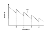
- FIG. 12 is a graph illustrating an example of a correction value for the operation time.
- FIG. 13 is a block diagram illustrating an example of an output model generation unit.
- FIG. 14 is a graph showing the relationship between the operation time of the gas turbine and the elapsed time since the periodic inspection.
- FIG. 15 is a graph showing the relationship between the operation time and the correction coefficient when periodic inspection is performed.
- FIG. 1 is a schematic diagram showing a gas turbine according to the present embodiment.
- the gas turbine 1 according to this embodiment includes a compressor 11, a combustor 12, and a turbine 13.
- a rotor 18 is disposed through the center of the compressor 11, the combustor 12, and the turbine 13, and the compressor 11 and the turbine 13 are coupled to each other by the rotor 18 so as to be integrally rotatable.
- the gas turbine 1 is controlled by a control device 14.
- the generator 15 is connected with the gas turbine 1, and electric power generation is possible.
- the gas turbine 1 also has a cooling air supply line 19 for supplying cooling air from the compressor 11 to the turbine 13.
- a cooling air control valve 20 is provided in the cooling air supply line 19.
- the compressor 11 compresses the air A taken in from the air intake port into compressed air A1.
- the compressor 11 is provided with an inlet guide vane (IGV: Inlet Guide Vane: intake valve) 22 that adjusts the intake amount of the air A taken in from the air intake.
- the intake air amount of the air A is adjusted by adjusting the opening degree of the inlet guide vane 22.
- the inlet guide vane 22 has a plurality of blade main bodies 22a and an IGV operating portion 22b for changing the blade angles of the plurality of blade main bodies 22a, and the blade angle of the blade main body 22a by the IGV operating portion 22b. Is adjusted, the opening degree of the inlet guide vane 22 is adjusted, and the intake amount of the air A is adjusted.
- the opening degree of the inlet guide vane 22 increases, the intake amount of the air A increases and the pressure ratio of the compressor 11 increases.
- the opening degree of the inlet guide vanes 22 decreases, so that the intake amount of the air A decreases, and the pressure ratio of the compressor 11 decreases.
- the combustor 12 supplies the fuel F to the compressed air A1 compressed by the compressor 11, mixes the compressed air A1 and the fuel F, and burns to generate combustion gas.
- the turbine 13 is rotated by the combustion gas generated by the combustor 12.
- the turbine 13 includes a rotor 18, a plurality of stages of stationary blades, and a plurality of stages of moving blades. The plurality of stages of stationary blades and the plurality of stages of moving blades are alternately provided in the axial direction of the rotor 18.
- the rotor 18 is rotatably supported at both axial ends by bearings (not shown), and is rotatable about the axis.
- the drive shaft of the generator 15 is connected to the end of the rotor 18 on the compressor 11 side.
- the generator 15 is provided coaxially with the turbine 13, and can generate power when the turbine 13 rotates.
- the air A taken in from the air intake port of the compressor 11 passes through the inside of the compressor 11 via the inlet guide vanes 22 and is compressed to become high-temperature / high-pressure compressed air A1.
- the fuel F is supplied from the combustor 12 to the compressed air A1, and the compressed air A1 and the fuel F are mixed and burned, whereby high-temperature and high-pressure combustion gas is generated.
- the high-temperature and high-pressure combustion gas generated in the combustor 12 passes through the inside of the turbine 13 to actuate (rotate) the turbine 13 to drive and rotate the rotor 18, and is connected to the rotor 18.
- the generator 15 is driven. Thereby, the generator 15 connected to the rotor 18 generates electric power by being rotationally driven.
- the combustion gas that has driven the turbine 13 recovers heat as exhaust gas and is released to the atmosphere.
- the gas turbine 1 is provided with a cabin pressure gauge 51, an intake state detector 52, a blade path thermometer 53, an exhaust gas thermometer 54, and a flow meter 55.
- the casing pressure gauge 51 is provided in a line through which the compressed air A1 flows from the compressor 11 toward the combustor 12, and is specifically provided in the interior of the casing of the combustor 12, and the pressure of the compressed air A1 (vehicle Measure the room pressure.
- the intake state detector 52 detects the intake temperature and intake pressure of the air A taken into the compressor 11.
- the blade path thermometer 53 is provided in a line through which the exhaust gas discharged from the turbine 13 circulates, and measures the temperature of the exhaust gas that has passed through the last stage blade provided downstream of the turbine 13 in the exhaust gas flow direction.
- the exhaust gas thermometer 54 is provided on the downstream side of the blade path thermometer 53 and measures the temperature of the exhaust gas.
- the flow meter 55 measures the flow rate of the cooling air flowing through the cooling air supply line 19.
- the gas turbine 1 is provided with an output meter 56 for detecting the output (load) of the gas turbine 1. Then, signals measured by the passenger compartment pressure gauge 51, the intake state detector 52, the blade path thermometer 53, the exhaust gas thermometer 54, the flow meter 55 and the output meter 56 are input to the control device 14.
- the control device 14 includes a control unit 61, a storage unit 62, and a processing unit (gas turbine characteristic evaluation device) 63.
- the control unit 61 controls the inlet guide vane 22, the fuel adjustment valve 35, and the like based on the measurement results of the cabin pressure gauge 51, the intake state detector 52, the blade path thermometer 53, the exhaust gas thermometer 54, the flow meter 55, and the like. To control the operation of the gas turbine 1. Further, the control unit 61 controls the operation of the gas turbine 1 according to the output of the gas turbine 1 (the output of the generator 15).
- control unit 61 determines the gas turbine characteristics and the inlet based on the measurement results of the cabin pressure gauge 51, the intake state detector 52, the blade path thermometer 53, the exhaust gas thermometer 54, the flow meter 55, and the output meter 56. Operation data such as pressure loss, outlet pressure loss, rotation speed, relative humidity, and operation time can be calculated.
- the gas turbine characteristics include characteristics for at least one of the compressor 11, the combustor 12, and the turbine 13. For example, the gas turbine characteristics include the output of the gas turbine 1, the intake air flow rate of the compressor 11, the efficiency of the compressor 11, the cabin pressure, and the like.
- the storage unit 62 stores various programs and data related to the operation of the gas turbine 1.
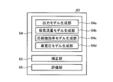
- FIG. 2 is a block diagram showing a configuration of the processing unit 63.
- the processing unit 63 includes a characteristic model generation unit 64, a correction unit 65, and an evaluation unit 66.
- the characteristic model generation unit 64 calculates a model value of the gas turbine characteristic based on the operation data of the gas turbine 1.
- the characteristic model generation unit 64 includes an output model generation unit 64a, an intake air flow model generation unit 64b, a compressor efficiency model generation unit 64c, and a vehicle interior pressure model generation unit 64d.
- the output model generation unit 64 a generates a model of output characteristics of the gas turbine 1.
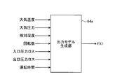
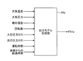
- FIG. 4 is a block diagram illustrating an example of the output model generation unit 64a.
- the output model generation unit 64a receives the atmospheric temperature, atmospheric pressure, relative humidity, rotation speed, inlet pressure loss, outlet pressure loss, and operation time as operation data.
- the output model generation unit 64a generates an output model FX1 that is a model of the output characteristics of the gas turbine 1 based on each of these operation data, and calculates a correction value for each transmission data based on the generated output model FX1.
- the output model generation unit 64a can use a known method such as linear multiple regression analysis, nonlinear multiple regression analysis, neural network, ensemble learning, and the like.
- the measured value and the reference value (measured value, reference value) of the operation data are respectively the atmospheric temperature (T, T0), atmospheric pressure (P, P0), relative humidity (H, H0), and rotation speed (R, R0).
- T, T0 atmospheric temperature
- P, P0 atmospheric pressure
- H, H0 relative humidity
- R, R0 rotation speed
- the output model FX1 is expressed by the following equation.
- FX1 ⁇ a (T ⁇ T0) ⁇ b (P ⁇ P0) ⁇ c (H ⁇ H0) ⁇ d (R ⁇ R0) -E (Pi-Pi0) -f (Pe-Pe0) -g (A-A0) + h
- a, b, c, d, e, f, g, and h are constants.
- h is a reference output (unit: MW).
- the reference values T0, P0, H0, R0, Pi0, Pe0, and A0 of the operation data are values under environmental conditions that serve as a reference for evaluating the output characteristics.
- the reference value can be set in advance.
- the output model generation unit 64a can obtain a correction value for each operation data using linear multiple regression analysis based on the generated output model.
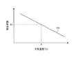
- FIG. 8 is a graph showing an example of a correction value for the atmospheric temperature.
- the vertical axis in FIG. 8 is the correction coefficient (correction value), and the horizontal axis is the atmospheric temperature.
- the straight line 101 of the atmospheric temperature obtained by the linear multiple regression analysis is, for example, a straight line such that the correction coefficient decreases as the atmospheric temperature increases.
- the characteristics such as the slope of the straight line 101 are merely examples, and the present invention is not limited to this.
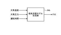
- FIG. 5 is a block diagram illustrating an example of the intake flow rate model generation unit 64b.
- the intake air flow rate model generation unit 64b receives the atmospheric temperature, atmospheric pressure, and operation time as operation data.
- the intake flow rate model generation unit 64b generates an intake flow rate model FX2 that is a model of the intake flow rate of the compressor 11 based on these operation data.
- the intake air flow model generation unit 64b generates an intake air flow model using a known method such as linear multiple regression analysis, nonlinear multiple regression analysis, neural network, ensemble learning, and the like. A correction value of each operation data can be obtained using regression analysis.
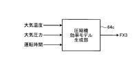
- FIG. 6 is a block diagram illustrating an example of the compressor efficiency model generation unit 64c.
- the compressor efficiency model generation unit 64c receives the atmospheric temperature, the atmospheric pressure, and the operation time as operation data. Similarly to the output model generation unit 64a, the compressor efficiency model generation unit 64c generates a compressor efficiency model FX3 that is a model of the efficiency of the compressor 11 based on these pieces of operation data.
- the compressor efficiency model generation unit 64c generates a compressor efficiency model using a known method such as linear multiple regression analysis, nonlinear multiple regression analysis, neural network, ensemble learning, and the like, and based on the generated compressor efficiency model.
- the correction value of each operation data can be obtained using linear multiple regression analysis.
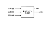
- FIG. 7 is a block diagram showing an example of the cabin pressure model generation unit 64d.
- the cabin pressure model generation unit 64d receives the atmospheric temperature, the atmospheric pressure, and the operation time as operation data. Similar to the output model generation unit 64a, the vehicle interior pressure model generation unit 64d generates a vehicle interior pressure model FX4 that is a model of the pressure characteristics (vehicle interior pressure characteristics) of the compressed air A1 based on these operation data. To do.
- the vehicle interior pressure model generating unit 64d generates a vehicle interior pressure model using a known method such as linear multiple regression analysis, nonlinear multiple regression analysis, neural network, ensemble learning, and the like, and based on the generated vehicle interior pressure model.
- the correction value of each operation data can be obtained using linear multiple regression analysis.
- the correction unit 65 shown in FIG. 2 obtains a corrected gas turbine characteristic obtained by removing or reducing the degree of influence due to environmental conditions for each gas turbine characteristic.
- the output of the gas turbine 1 will be described as an example of the gas turbine characteristics.
- the correction value for the atmospheric temperature is K1
- the correction value for the atmospheric pressure is K2
- the correction value for the relative humidity is K3
- the correction value for the rotational speed is K4
- the inlet pressure If the correction value for the loss is K5, the correction value for the outlet pressure loss is K6, the correction value for the operating time is K7, and the detection result of the output meter 56 is G
- G ' G / (K1, K2, K3, K4, K5, K6, K7)
- the value of the intake flow rate is X
- the value of the compressor efficiency is Y
- the value of the cabin pressure is Z.
- the intake air flow rate X ′, the compressor efficiency Y ′, and the passenger compartment pressure Z ′ can be obtained as follows.
- the evaluation unit 66 evaluates the corrected gas turbine characteristics obtained.
- the output G ′ corrected by the correction unit 65 is a value from which the influence due to the environmental condition is removed or reduced. Therefore, the evaluation unit 66 can evaluate a change in the output of the gas turbine 1 due to dirt, deterioration, or the like based on the output G ′ obtained by the correction unit 65, for example. In this case, the evaluation can be performed by obtaining in advance a reference value of the output of the gas turbine 1 under reference environmental conditions and comparing it with the reference value.
- the reference value can be, for example, the output of the gas turbine 1 in a state where there is no dirt or deterioration under the reference environmental conditions, or in a state where the dirt or deterioration is less than a predetermined threshold. Further, the evaluation unit 66 may evaluate the cause of the output change based on the difference between the reference value and the measured value of the output of the gas turbine 1.
- the evaluation unit 66 similarly changes the gas turbine characteristics due to dirt, deterioration, etc. based on the gas turbine characteristics corrected by the correction unit 65 for the intake air flow rate, the compressor efficiency, and the passenger compartment pressure, It is possible to evaluate factors that cause changes in gas turbine characteristics.
- each characteristic model is generated using linear multiple regression analysis. For this reason, when operation data such as atmospheric temperature is input to the output model generation unit 64a, the intake air flow rate model generation unit 64b, the compressor efficiency model generation unit 64c, and the cabin pressure model generation unit 64d, the theoretical values are used. Characteristics (output, intake air flow rate, compressor efficiency, and cabin pressure) are calculated. This characteristic is a value corresponding to the gas turbine characteristic corrected based on the correction value. Therefore, the evaluation unit 66 may perform the evaluation by comparing the measured values of the output, the intake air flow rate, the compressor efficiency, and the passenger compartment pressure with the theoretical values calculated by the linear multiple regression analysis.
- the value of the operation time is input to each unit of the characteristic model generation unit 64 as operation data. For this reason, the degree to which the gas turbine characteristics change over time, that is, the degree to which the gas turbine characteristics change due to deterioration is calculated. Therefore, the evaluation unit 66 may evaluate the deterioration by comparing the corrected gas turbine characteristic with the calculated degree of change in the gas turbine characteristic due to the deterioration.
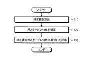
- FIG. 3 is a flowchart illustrating an example of a gas turbine characteristic evaluation method.
- the processing unit 63 calculates a correction value for correcting the influence on the gas turbine characteristics due to environmental conditions (step S ⁇ b> 10).
- the characteristic model generation unit 64 generates a characteristic model for each characteristic of the gas turbine 1 and calculates a correction value for the operation data based on the generated characteristic model.
- step S20 the processing unit 63 corrects the gas turbine characteristics based on the calculated correction value (step S20).
- the correction unit 65 obtains the corrected gas turbine characteristic in the reference environmental condition based on the correction value calculated for each gas turbine characteristic.
- the corrected gas turbine characteristic is a value in which the influence of environmental conditions is removed or reduced.
- step S30 the processing unit 63 evaluates based on the corrected gas turbine characteristics (step S30).
- the evaluation unit 66 evaluates the gas turbine characteristics by comparing the corrected gas turbine characteristics with the measured values of the gas turbine characteristics. Since the evaluation is based on the gas turbine characteristics in which the influence by the environmental conditions is removed or reduced, a highly accurate evaluation can be obtained.
- the gas turbine characteristic evaluation apparatus calculates a correction value for correcting the influence due to the environmental conditions based on the operation data of the gas turbine 1, and therefore provides a highly accurate correction value. Obtainable. Based on this correction value, the gas turbine characteristic is corrected, and the gas turbine characteristic is evaluated by comparing the corrected gas turbine characteristic with a predetermined reference value. Therefore, highly accurate evaluation can be performed.
- the gas turbine characteristic evaluation apparatus can calculate the degree of change in the gas turbine characteristics due to deterioration. Accordingly, it is possible to evaluate the deterioration characteristics according to the environmental conditions set for each gas turbine 1 and the individual operation data for each gas turbine 1, so that highly accurate evaluation can be performed.
- the technical scope of the present invention is not limited to the above-described embodiment, and appropriate modifications can be made without departing from the spirit of the present invention.
- the characteristic model generation unit 64 generates a characteristic model using linear multiple regression analysis has been described as an example.
- the present invention is not limited to this, and the characteristic model is generated by a non-linear method. May be generated.
- the characteristic model generation unit 64 can generate a characteristic model using, for example, a neural network as a nonlinear technique.
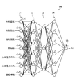
- FIG. 9 is a diagram schematically showing how a characteristic model is generated using a hierarchical neural network.
- the output model generation unit 64e that outputs the output model FX1 will be described as an example of the characteristic model generation unit.
- the output model generation unit 64e includes a first layer L1 that is an input layer, a second layer L2, a third layer L3, and a fourth layer L4 that are intermediate layers, and a fifth layer L5 that is an output layer. Yes.
- the output model generation unit 64e has a configuration in which the intermediate layer has three layers, but is not limited thereto, and may have a configuration in which the intermediate layer has two layers or less or four layers or more.
- the first layer L1, the second layer L2, the third layer L3, the fourth layer L4, and the fifth layer L5 have one or a plurality of nodes n.
- the first layer L1 has seven nodes n (n1, n2, n3, n4, n5, n6, n7).
- An atmospheric temperature is input to the node n1.
- Atmospheric pressure is input to the node n2.
- the relative humidity is input to the node n3.
- the rotation speed is input to the node n4.
- An inlet pressure loss is input to the node n5.
- An outlet pressure loss is input to the node n6.
- the operation time is input to the node n7.
- the seven nodes n of the first layer L1 output signals to the nodes n of the second layer L2.
- the second layer L2 has, for example, six nodes n.
- the signals output from the seven nodes n of the first layer L1 are input to the six nodes n of the second layer L2.
- the six nodes n of the second layer L2 output signals to the nodes n of the third layer L3.
- the number of nodes n is not limited to six, and may be five or less or seven or more.
- the second layer L3 has three nodes n.
- the signals output from the six nodes n of the second layer L2 are input to the three nodes n of the third layer L3.
- the six nodes n in the third layer L3 output signals to the respective nodes n in the fourth layer L4.
- the number of nodes n is not limited to three, and may be two or less or four or more.
- the fourth layer L4 has six nodes n.
- the signals output from the three nodes n of the third layer L3 are input to the six nodes n of the fourth layer L4.
- the six nodes n in the fourth layer L4 output signals to the node n in the fifth layer L5.
- the number of nodes n is not limited to six, and may be five or less or seven or more.
- the fifth layer L5 has one node n.
- the signals output from the six nodes n of the fourth layer L4 are input to the three nodes n of the fifth layer L5.
- the node n of the fifth layer L5 outputs the output model FX1.
- the number of nodes n is not limited to one and may be two or more.
- the intake flow rate model generating unit that outputs the intake flow rate model FX2 the compressor efficiency model generating unit that outputs the compressor efficiency model FX3, and the vehicle interior pressure model generating unit that outputs the vehicle interior pressure model FX4 are also as described above.
- a configuration may be used in which each characteristic model is output using a simple neural network. In this case, the number of nodes in the input layer, the number of layers in the intermediate layer, and the number of nodes in each layer can be appropriately changed according to the type of input signal.
- FIG. 9 the case where a hierarchical neural network is used has been described as an example.
- the present invention is not limited to this, and a neural network different from the hierarchical neural network, such as an interconnected neural network, is used. It may be a configuration.
- FIG. 10 is a graph showing an example of correction values for the atmospheric temperature.
- the vertical axis in FIG. 10 is the correction coefficient (correction value), and the horizontal axis is the atmospheric temperature.
- the atmospheric temperature curve 102 is curved, and the amount of decrease in the correction coefficient decreases as the atmospheric temperature increases, for example.
- a non-linear method such as the neural network shown in FIG. 9, it is possible to obtain not only a linear shape but also a curved curve 102, thereby obtaining a more accurate correction value. it can. For example, even when it is difficult to grasp the characteristics in advance, such as a change in the output of the gas turbine 1 with respect to the operation time, a more accurate correction value can be obtained.
- the characteristic model generation unit 64 may sequentially update the characteristic model of the gas turbine characteristic.
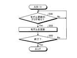
- FIG. 11 is a flowchart showing a procedure for updating the characteristic model.
- the characteristic model generation unit 64 detects the presence or absence of a flag for updating the characteristic model (step S40).
- a flag for updating the characteristic model for example, when a predetermined period has elapsed (for example, when one day has elapsed, one week has elapsed, one month has elapsed, etc.), or predetermined periodic inspection It can be generated when, for example, is performed.
- the characteristic model generation unit 64 repeats Step S40.
- the characteristic model generation unit 64 updates the characteristic model of the gas turbine characteristic (step S50).
- step S50 the characteristic model generation unit 64 newly generates a characteristic model based on the input operation data. Since the generated characteristic model is newly generated in a state where the operation data since the previous generation of the characteristic model has been accumulated, it becomes a more accurate characteristic model.
- the characteristic model generation unit 64 calculates a correction value for each operation data based on the generated characteristic model.
- the correction unit 65 corrects the gas turbine characteristics based on the newly calculated correction value.
- the evaluation unit 66 performs an evaluation based on the gas turbine characteristics corrected based on the new correction value. For this reason, highly accurate evaluation is obtained.
- the characteristic model generation unit 64 After updating the characteristic model, the characteristic model generation unit 64 repeatedly performs the operation from step S40 when the operation of the gas turbine 1 is not completed (No in step S60). When the operation of the gas turbine 1 is finished (Yes in step S60), the characteristic model generation unit 64 finishes the above process.
- the characteristic model generation unit 64 can calculate the correction value based on the accumulated operation data by updating the characteristic model. Thereby, when the gas turbine characteristic corrected based on the correction value is evaluated, a highly accurate evaluation is obtained.
- the characteristic model generation unit 64 may predict and calculate a future correction value based on the obtained correction value.
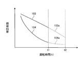
- FIG. 12 is a graph illustrating an example of a correction value for the operation time.
- the vertical axis in FIG. 12 is the correction coefficient (correction value), and the horizontal axis is the operating time.
- correction values up to time t1 are calculated as correction values for operating time.
- the straight line 103 is a correction value obtained by, for example, linear multiple regression analysis.
- a curve 104 is a correction value obtained by, for example, a nonlinear method. In any case, correction values up to time t1 are calculated.
- the characteristic model generation unit 64 may predict a future correction value, for example, a correction value until time t2 after time t1 based on the tendency of the straight line 103 and the curve 104.
- a straight line 103 a and a curve 104 a indicate correction values predicted based on the straight line 103 and the curve 104.
- the correction unit 65 may calculate the corrected gas turbine characteristic in the future by correcting the gas turbine characteristic based on the predicted correction value.
- the evaluation unit 66 may perform evaluation based on the calculated future corrected gas turbine characteristics. Thereby, the evaluation regarding the future gas turbine characteristic can be obtained.
- the output model generation unit 64a takes as an example a configuration in which atmospheric temperature, atmospheric pressure, relative humidity, rotation speed, inlet pressure loss, outlet pressure loss, and operation time are input as operation data.
- the present invention is not limited to this, and other operation data may be input.
- FIG. 13 is a block diagram illustrating an example of the output model generation unit 64a.
- the output model generation unit 64a may be configured to receive data on elapsed time since the periodic inspection in addition to the above operation data.
- the output model generation unit 64a generates an output model FX1a that is a model of the output characteristics of the gas turbine 1 based on each of these operation data, and calculates a correction value for each transmission data based on the generated output model FX1a. To do.
- FIG. 14 is a graph showing the relationship between the operation time of the gas turbine 1 and the elapsed time since the periodic inspection.
- the periodic inspection of the gas turbine 1 is periodically performed at, for example, times t3, t4, t5, and t6 from the start of operation.
- a broken line 105 indicates a state in which the elapsed time is reset for each periodic inspection.
- the periodic inspection includes, for example, a combustor inspection that is an inspection of the combustor 12, a turbine inspection that is an inspection of the turbine 13, and a major inspection. Combustor inspection is also performed by performing turbine inspection. By performing a major inspection, a turbine inspection and a combustor inspection are also performed.
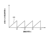
- FIG. 15 is a graph showing the relationship between the operation time and the correction coefficient when the periodic inspection is performed.
- the output model generation unit 64a corrects the correction value so that the influence of the output increase is excluded or reduced at each of the times t3, t4, t5, and t6 when the periodic inspection is performed from the start of operation. Is calculated.
- the shape of the broken line 106 indicating the correction value is in a state of rapidly rising at, for example, times t3, t4, t5, and t6.
Abstract
Description
-e(Pi-Pi0)-f(Pe-Pe0)-g(A-A0)+h FX1 = −a (T−T0) −b (P−P0) −c (H−H0) −d (R−R0)
-E (Pi-Pi0) -f (Pe-Pe0) -g (A-A0) + h
11 圧縮機
12 燃焼器
13 タービン
14 制御装置
15 発電機
18 ロータ
19 冷却用空気供給ライン
20 冷却用空気制御弁
22 入口案内翼
22a 翼本体
22b IGV作動部
35 燃料調整弁
51 車室圧力計
52 吸気状態検出器
53 ブレードパス温度計
54 排ガス温度計
55 流量計
56 出力計
61 制御部
62 記憶部
63 処理部
64 特性モデル生成部
64a,64e 出力モデル生成部
64b 吸気流量モデル生成部
64c 圧縮機効率モデル生成部
64d 車室圧モデル生成部
65 補正部
66 評価部
101,103,103a 直線
102,104,104a 曲線
105,106 折れ線
A 空気
A1 圧縮空気
F 燃料
H0,P0,R0,T0,Pe0,Pi0 基準値
FX1,FX1a 出力モデル
FX2 吸気流量モデル
FX3 圧縮機効率モデル
FX4 車室圧モデル
L1 第1層
L2 第2層
L3 第3層
L4 第4層
L5 第5層
n,n1,n2,n3,n4,n5,n6,n7 ノード
t1,t2,t3,t4,t5,t6 時刻 DESCRIPTION OF
Claims (5)
- 空気を圧縮する圧縮機と、
燃料が供給され前記圧縮機で圧縮された圧縮空気を燃焼させる燃焼器と、
前記燃焼器で生じた燃焼ガスにより回転するタービンと、
を備えるガスタービンの特性評価装置であって、
前記圧縮機、前記燃焼器及び前記タービンのうち少なくとも1つについての特性を含むガスタービン特性のうち前記ガスタービンが配置される環境条件による影響を補正するための補正値を前記ガスタービンの運転データに基づいて算出し、前記補正値に基づいて補正された前記ガスタービン特性を算出し、補正後の前記ガスタービン特性と所定の基準値とを比較することにより前記ガスタービンの評価を行う処理部を備える、ガスタービンの特性評価装置。 A compressor for compressing air;
A combustor for burning compressed air supplied with fuel and compressed by the compressor;
A turbine rotating by combustion gas generated in the combustor;
A gas turbine characteristic evaluation apparatus comprising:
Operation data of the gas turbine is used as a correction value for correcting an influence due to an environmental condition in which the gas turbine is arranged among gas turbine characteristics including characteristics of at least one of the compressor, the combustor, and the turbine. A processing unit that calculates the gas turbine characteristics corrected based on the correction value and evaluates the gas turbine by comparing the corrected gas turbine characteristics with a predetermined reference value A gas turbine characteristic evaluation apparatus comprising: - 前記処理部は、前記運転データに基づいて前記ガスタービン特性のモデル値を算出し、前記モデル値に基づいて前記補正値を推定する請求項1に記載のガスタービンの特性評価装置。 The gas turbine characteristic evaluation device according to claim 1, wherein the processing unit calculates a model value of the gas turbine characteristic based on the operation data, and estimates the correction value based on the model value.
- 前記ガスタービン特性は、前記ガスタービンの出力、前記圧縮機の吸気流量、前記圧縮機の効率、前記圧縮空気の圧力のうち少なくとも1つを含む請求項1又は請求項2に記載のガスタービンの特性評価装置。 3. The gas turbine according to claim 1, wherein the gas turbine characteristics include at least one of an output of the gas turbine, an intake air flow rate of the compressor, an efficiency of the compressor, and a pressure of the compressed air. Characteristic evaluation device.
- 前記運転データは、前記ガスタービンが配置される環境における大気温度、大気圧力、及び前記ガスタービンの運転時間を含む請求項1から請求項3のいずれか一項に記載のガスタービンの特性評価装置。 The gas turbine characteristic evaluation device according to any one of claims 1 to 3, wherein the operation data includes an atmospheric temperature, an atmospheric pressure, and an operation time of the gas turbine in an environment in which the gas turbine is disposed. .
- 空気を圧縮する圧縮機と、
燃料が供給され前記圧縮機で圧縮された圧縮空気を燃焼させる燃焼器と、
前記燃焼器で生じた燃焼ガスにより回転するタービンと、
を備えるガスタービンの特性評価方法であって、
前記圧縮機、前記燃焼器及び前記タービンのうち少なくとも1つについての特性を含むガスタービン特性のうち前記ガスタービンが配置される環境条件による影響を補正するための補正値を前記ガスタービンの運転データに基づいて算出することと、
前記補正値に基づいて補正された前記ガスタービン特性を算出することと、
補正後の前記ガスタービン特性と所定の基準値とを比較することにより前記ガスタービンの評価を行うことと、
を含むガスタービンの特性評価方法。 A compressor for compressing air;
A combustor for burning compressed air supplied with fuel and compressed by the compressor;
A turbine rotating by combustion gas generated in the combustor;
A gas turbine characteristic evaluation method comprising:
Operation data of the gas turbine is used as a correction value for correcting an influence due to an environmental condition in which the gas turbine is arranged among gas turbine characteristics including characteristics of at least one of the compressor, the combustor, and the turbine. To calculate based on
Calculating the gas turbine characteristic corrected based on the correction value;
Evaluating the gas turbine by comparing the corrected gas turbine characteristics with a predetermined reference value;
Of gas turbine characteristics including
Priority Applications (6)
| Application Number | Priority Date | Filing Date | Title |
|---|---|---|---|
| KR1020187026829A KR20180110678A (en) | 2016-03-22 | 2016-11-28 | Apparatus for evaluating characteristics of gas turbine and evaluation method of characteristics of gas turbine |
| US16/083,282 US10636224B2 (en) | 2016-03-22 | 2016-11-28 | Characteristic evaluation device for gas turbine and characteristic evaluation method for gas turbine |
| CN201680083800.1A CN108779713B (en) | 2016-03-22 | 2016-11-28 | Gas turbine characteristic evaluation device and gas turbine characteristic evaluation method |
| MX2018011093A MX2018011093A (en) | 2016-03-22 | 2016-11-28 | Gas turbine characteristic evaluation device and gas turbine characteristic evaluation method. |
| DE112016006642.2T DE112016006642B4 (en) | 2016-03-22 | 2016-11-28 | GAS TURBINE PROPERTIES EVALUATION DEVICE AND GAS TURBINE PROPERTIES EVALUATION METHOD |
| PH12018502009A PH12018502009A1 (en) | 2016-03-22 | 2018-09-19 | Characteristic evaluation device for gas turbine and characteristic evaluation method for gas turbine |
Applications Claiming Priority (2)
| Application Number | Priority Date | Filing Date | Title |
|---|---|---|---|
| JP2016057187A JP6786233B2 (en) | 2016-03-22 | 2016-03-22 | Gas turbine characterization device and gas turbine characterization method |
| JP2016-057187 | 2016-03-22 |
Publications (1)
| Publication Number | Publication Date |
|---|---|
| WO2017163489A1 true WO2017163489A1 (en) | 2017-09-28 |
Family
ID=59901089
Family Applications (1)
| Application Number | Title | Priority Date | Filing Date |
|---|---|---|---|
| PCT/JP2016/085176 WO2017163489A1 (en) | 2016-03-22 | 2016-11-28 | Gas turbine characteristic evaluation device and gas turbine characteristic evaluation method |
Country Status (8)
| Country | Link |
|---|---|
| US (1) | US10636224B2 (en) |
| JP (1) | JP6786233B2 (en) |
| KR (1) | KR20180110678A (en) |
| CN (1) | CN108779713B (en) |
| DE (1) | DE112016006642B4 (en) |
| MX (1) | MX2018011093A (en) |
| PH (1) | PH12018502009A1 (en) |
| WO (1) | WO2017163489A1 (en) |
Families Citing this family (4)
| Publication number | Priority date | Publication date | Assignee | Title |
|---|---|---|---|---|
| CA3135985A1 (en) | 2019-05-13 | 2020-11-19 | Rudy Charles Andre AULNETTE | Model resetting in a turbine engine |
| FR3096137B1 (en) * | 2019-05-13 | 2021-04-23 | Safran Aircraft Engines | PS3 model registration in a turbomachine |
| KR102452608B1 (en) * | 2021-03-04 | 2022-10-07 | 인하대학교 산학협력단 | Method for Gas turbine control based on artificial intelligence and apparatus thereof |
| JP7458357B2 (en) | 2021-09-24 | 2024-03-29 | 三菱パワー株式会社 | Model learning device, performance evaluation device, model learning method, and program |
Citations (2)
| Publication number | Priority date | Publication date | Assignee | Title |
|---|---|---|---|---|
| JP2002073156A (en) * | 2000-09-04 | 2002-03-12 | Kawasaki Heavy Ind Ltd | Method and device for diagnosing gas turbine operating state |
| JP2003083089A (en) * | 2001-09-14 | 2003-03-19 | Ishikawajima Harima Heavy Ind Co Ltd | Performance diagnosis method for gas turbine |
Family Cites Families (45)
| Publication number | Priority date | Publication date | Assignee | Title |
|---|---|---|---|---|
| JPH05195720A (en) * | 1992-01-21 | 1993-08-03 | Toshiba Corp | Managing method for degradation in performance of plant |
| US6823675B2 (en) * | 2002-11-13 | 2004-11-30 | General Electric Company | Adaptive model-based control systems and methods for controlling a gas turbine |
| US7577549B2 (en) | 2005-07-18 | 2009-08-18 | General Electric Company | System and method for trending exhaust gas temperature in a turbine engine |
| JP4801452B2 (en) | 2006-01-19 | 2011-10-26 | 三菱重工業株式会社 | Abnormality monitoring method and apparatus for gas turbine |
| US20110106680A1 (en) | 2009-10-30 | 2011-05-05 | General Electric Company | Turbine operation degradation determination system and method |
| US8171717B2 (en) * | 2010-05-14 | 2012-05-08 | General Electric Company | Model-based coordinated air-fuel control for a gas turbine |
| US8423161B2 (en) * | 2011-08-24 | 2013-04-16 | General Electric Company | Methods and systems for gas turbine modeling using adaptive kalman filter |
| US20130066615A1 (en) * | 2011-09-14 | 2013-03-14 | General Electric Company | System and method for simulating gas turbine operation |
| US8452515B2 (en) * | 2011-09-15 | 2013-05-28 | General Electric Company | System and method for simulating a gas turbine compressor |
| US9322333B2 (en) * | 2012-01-06 | 2016-04-26 | General Electric Company | System and method for determining a cooling flow parameter downstream from a gas turbine combustor |
| JP6236004B2 (en) * | 2012-08-03 | 2017-11-22 | 株式会社日立製作所 | Two-shaft gas turbine power generation system, control device and control method for gas turbine system |
| US9540944B2 (en) * | 2012-09-28 | 2017-01-10 | United Technologies Corporation | Real time model based compressor control |
| CN102953835B (en) * | 2012-11-09 | 2014-11-19 | 沈阳黎明航空发动机(集团)有限责任公司 | Control device and control method for stable running of gas turbine |
| JP6116871B2 (en) * | 2012-11-22 | 2017-04-19 | 三菱日立パワーシステムズ株式会社 | Power generation system and method for operating power generation system |
| US9255525B2 (en) * | 2012-11-30 | 2016-02-09 | General Electric Company | System and method for gas turbine operation |
| EP2738373A1 (en) * | 2012-12-03 | 2014-06-04 | Siemens Aktiengesellschaft | Gas turbine fuel supply method and arrangement |
| EP2738374A1 (en) * | 2012-12-03 | 2014-06-04 | Siemens Aktiengesellschaft | Method and arrangement for controlling fuel supply for a gas turbine |
| US10208677B2 (en) * | 2012-12-31 | 2019-02-19 | General Electric Company | Gas turbine load control system |
| US9291093B2 (en) * | 2013-02-08 | 2016-03-22 | GM Global Technology Operations LLC | Turbocharger flow control |
| US9856795B2 (en) * | 2013-02-26 | 2018-01-02 | Mitsubishi Hitachi Power Systems, Ltd. | Gas turbine system, controller, and gas turbine operation method |
| US9014945B2 (en) * | 2013-03-08 | 2015-04-21 | General Electric Company | Online enhancement for improved gas turbine performance |
| US10161313B2 (en) * | 2013-03-15 | 2018-12-25 | United Technologies Corporation | Compact aero-thermo model based engine material temperature control |
| GB201313140D0 (en) * | 2013-07-23 | 2013-09-04 | Rolls Royce Engine Control Systems Ltd | System for performing staging control of a multi-stage combustor |
| US9696697B2 (en) * | 2013-09-04 | 2017-07-04 | General Electric Company | Automatic switching of HMI screens based on process, task, and abnormal deviation in a power plant |
| ITBO20130480A1 (en) * | 2013-09-10 | 2015-03-11 | Magneti Marelli Spa | METHOD OF CORRECTION OF THE REDUCED MASS CAPACITY OF A COMPRESSOR IN AN INTERNAL TURBOCHROME COMBUSTION ENGINE BY A TURBOCHARGER |
| DE112014004262T5 (en) * | 2013-09-17 | 2016-06-23 | General Electric Company | System and method for controlling the operation of a gas turbine-based unit |
| EP2868898A1 (en) * | 2013-10-30 | 2015-05-06 | Siemens Aktiengesellschaft | Improved partial load operation of a gas turbine with an adjustable bypass flow channel |
| US20160252015A1 (en) * | 2013-11-27 | 2016-09-01 | Hitachi, Ltd. | Gas Turbine Corresponding to Renewable Energy and Control Method Therefor |
| US9453767B2 (en) * | 2013-12-18 | 2016-09-27 | Siemens Energy, Inc. | Active temperature monitoring in gas turbine combustors |
| US20150184549A1 (en) * | 2013-12-31 | 2015-07-02 | General Electric Company | Methods and systems for enhancing control of power plant generating units |
| US9404426B2 (en) * | 2013-12-31 | 2016-08-02 | General Electric Company | Methods and systems for enhancing control of power plant generating units |
| US9863267B2 (en) * | 2014-01-21 | 2018-01-09 | General Electric Company | System and method of control for a gas turbine engine |
| JP6257035B2 (en) * | 2014-03-25 | 2018-01-10 | 三菱日立パワーシステムズ株式会社 | Combustion control device, combustion control method and program for gas turbine |
| WO2015193979A1 (en) * | 2014-06-18 | 2015-12-23 | 株式会社日立製作所 | Multi-shaft variable-speed gas turbine device and control method therefor |
| US9885290B2 (en) * | 2014-06-30 | 2018-02-06 | General Electric Company | Erosion suppression system and method in an exhaust gas recirculation gas turbine system |
| EP2966525A1 (en) * | 2014-07-11 | 2016-01-13 | Alstom Technology Ltd | Method for the control and protection of a gas turbine and gas turbine using such method |
| US9528913B2 (en) * | 2014-07-24 | 2016-12-27 | General Electric Company | Method and systems for detection of compressor surge |
| US20160147204A1 (en) * | 2014-11-26 | 2016-05-26 | General Electric Company | Methods and systems for enhancing control of power plant generating units |
| US9932850B2 (en) * | 2015-02-03 | 2018-04-03 | General Electric Company | Correction system and method for gas turbine proportional droop governor |
| US10287988B2 (en) * | 2015-03-27 | 2019-05-14 | General Electric Company | Methods and systems for enhancing operation of power plant generating units and systems |
| JP6248993B2 (en) * | 2015-07-31 | 2017-12-20 | トヨタ自動車株式会社 | Control device for internal combustion engine |
| GB2532593A (en) * | 2015-10-12 | 2016-05-25 | Gm Global Tech Operations Llc | A method of controlling the operation of an air charging system of an internal combustion engine |
| US10466661B2 (en) * | 2015-12-18 | 2019-11-05 | General Electric Company | Model-based performance estimation |
| JP6706936B2 (en) * | 2016-03-09 | 2020-06-10 | 三菱日立パワーシステムズ株式会社 | Gas turbine control device and gas turbine control method |
| KR101971337B1 (en) * | 2017-04-24 | 2019-04-22 | 두산중공업 주식회사 | Gas Turbine System and Controlling Method thereof |
-
2016
- 2016-03-22 JP JP2016057187A patent/JP6786233B2/en active Active
- 2016-11-28 MX MX2018011093A patent/MX2018011093A/en unknown
- 2016-11-28 CN CN201680083800.1A patent/CN108779713B/en active Active
- 2016-11-28 WO PCT/JP2016/085176 patent/WO2017163489A1/en active Application Filing
- 2016-11-28 DE DE112016006642.2T patent/DE112016006642B4/en active Active
- 2016-11-28 US US16/083,282 patent/US10636224B2/en active Active
- 2016-11-28 KR KR1020187026829A patent/KR20180110678A/en not_active Application Discontinuation
-
2018
- 2018-09-19 PH PH12018502009A patent/PH12018502009A1/en unknown
Patent Citations (2)
| Publication number | Priority date | Publication date | Assignee | Title |
|---|---|---|---|---|
| JP2002073156A (en) * | 2000-09-04 | 2002-03-12 | Kawasaki Heavy Ind Ltd | Method and device for diagnosing gas turbine operating state |
| JP2003083089A (en) * | 2001-09-14 | 2003-03-19 | Ishikawajima Harima Heavy Ind Co Ltd | Performance diagnosis method for gas turbine |
Also Published As
| Publication number | Publication date |
|---|---|
| MX2018011093A (en) | 2018-11-22 |
| US20190080523A1 (en) | 2019-03-14 |
| PH12018502009A1 (en) | 2019-07-01 |
| US10636224B2 (en) | 2020-04-28 |
| CN108779713A (en) | 2018-11-09 |
| KR20180110678A (en) | 2018-10-10 |
| CN108779713B (en) | 2020-11-13 |
| JP2017172391A (en) | 2017-09-28 |
| JP6786233B2 (en) | 2020-11-18 |
| DE112016006642T5 (en) | 2018-12-20 |
| DE112016006642B4 (en) | 2023-07-06 |
Similar Documents
| Publication | Publication Date | Title |
|---|---|---|
| WO2017163489A1 (en) | Gas turbine characteristic evaluation device and gas turbine characteristic evaluation method | |
| US8452515B2 (en) | System and method for simulating a gas turbine compressor | |
| US8014929B2 (en) | Method of monitoring a gas turbine engine | |
| RU2406990C1 (en) | Procedure for operating gas turbine installation | |
| EP2570877A1 (en) | System and method for simulating gas turbine operation | |
| JP2003129866A (en) | Adaptive aero-thermodynamic engine model | |
| JP6636021B2 (en) | How to identify emission behavior | |
| JP2007138921A (en) | Estimation of repetition of model base of gas turbine engine component quality | |
| KR102120733B1 (en) | Diagnosis of defects during the test of the turbine unit | |
| US20070203669A1 (en) | Performance monitoring method and system for a single shaft combined cycle plant | |
| JP2018204604A (en) | Systems and methods for icing detection of compressors | |
| US11149654B2 (en) | Systems, program products, and methods for adjusting operating limit (OL) threshold for compressors of gas turbine systems based on mass flow loss | |
| US20170350271A1 (en) | Adaptive model-based method to quantify degradation of a power generation system | |
| KR101878625B1 (en) | State determining device, operation control device, gas turbine, and state determining method | |
| JP6906935B2 (en) | Equipment-specific stochastic controls, related control systems, computer program products, and methods for gas turbine regulation with respect to output-emission parameters. | |
| CN106050435B (en) | Regulation and control system, computer program product and method for a gas turbine | |
| US20160305343A1 (en) | Application of probabilistic control in gas turbine tuning for emissions-fuel flow parameters, related control systems, computer program products and methods | |
| JP6640534B2 (en) | Control system, computer program product, and method associated with application of fuel flow based stochastic control in gas turbine tuning under partial load | |
| CN105604703B (en) | For tuning computing device, the system and method for combustion gas turbine | |
| US20140358452A1 (en) | Method for estimating crack length progressions | |
| EP3373083A1 (en) | Power generation system control through adaptive learning | |
| US11225882B2 (en) | Method and apparatus for determining a present value based on previously obtained values of a measured variable of a gas turbine engine and/or a thermodynamic process | |
| US20160305344A1 (en) | Application of probabilistic control in gas turbine tuning for fuel flow-exhaust energy parameters, related control systems, computer program products and methods | |
| JP2001329855A (en) | Predicting method for turbine inlet temperature of gas turbine | |
| JP6666122B2 (en) | Control system, computer program product, and method related to applying stochastic control in gas turbine tuning in response to measurement error |
Legal Events
| Date | Code | Title | Description |
|---|---|---|---|
| WWE | Wipo information: entry into national phase |
Ref document number: MX/A/2018/011093 Country of ref document: MX |
|
| ENP | Entry into the national phase |
Ref document number: 20187026829 Country of ref document: KR Kind code of ref document: A |
|
| WWE | Wipo information: entry into national phase |
Ref document number: 1020187026829 Country of ref document: KR |
|
| 121 | Ep: the epo has been informed by wipo that ep was designated in this application |
Ref document number: 16895512 Country of ref document: EP Kind code of ref document: A1 |
|
| 122 | Ep: pct application non-entry in european phase |
Ref document number: 16895512 Country of ref document: EP Kind code of ref document: A1 |