EP2868898A1 - Improved partial load operation of a gas turbine with an adjustable bypass flow channel - Google Patents
Improved partial load operation of a gas turbine with an adjustable bypass flow channel Download PDFInfo
- Publication number
- EP2868898A1 EP2868898A1 EP20130190849 EP13190849A EP2868898A1 EP 2868898 A1 EP2868898 A1 EP 2868898A1 EP 20130190849 EP20130190849 EP 20130190849 EP 13190849 A EP13190849 A EP 13190849A EP 2868898 A1 EP2868898 A1 EP 2868898A1
- Authority
- EP
- European Patent Office
- Prior art keywords
- combustion chamber
- section
- opening cross
- gas turbine
- bypass flow
- Prior art date
- Legal status (The legal status is an assumption and is not a legal conclusion. Google has not performed a legal analysis and makes no representation as to the accuracy of the status listed.)
- Withdrawn
Links
- 238000002485 combustion reaction Methods 0.000 claims abstract description 111
- 239000000463 material Substances 0.000 claims abstract description 22
- 238000000034 method Methods 0.000 claims description 48
- 238000001816 cooling Methods 0.000 claims description 31
- 230000009467 reduction Effects 0.000 claims description 17
- 239000000523 sample Substances 0.000 claims description 6
- 238000011017 operating method Methods 0.000 abstract 1
- 239000007789 gas Substances 0.000 description 85
- 230000003068 static effect Effects 0.000 description 4
- 230000003247 decreasing effect Effects 0.000 description 3
- 230000033228 biological regulation Effects 0.000 description 2
- 238000004364 calculation method Methods 0.000 description 2
- 230000006378 damage Effects 0.000 description 2
- 230000007423 decrease Effects 0.000 description 2
- 230000006641 stabilisation Effects 0.000 description 2
- 238000011105 stabilization Methods 0.000 description 2
- 230000001133 acceleration Effects 0.000 description 1
- 230000015572 biosynthetic process Effects 0.000 description 1
- 238000006243 chemical reaction Methods 0.000 description 1
- 239000000567 combustion gas Substances 0.000 description 1
- 230000001419 dependent effect Effects 0.000 description 1
- 230000000694 effects Effects 0.000 description 1
- 239000000446 fuel Substances 0.000 description 1
- 238000005259 measurement Methods 0.000 description 1
- 238000013021 overheating Methods 0.000 description 1
- 230000003685 thermal hair damage Effects 0.000 description 1
- 238000011144 upstream manufacturing Methods 0.000 description 1
Images

Classifications
-
- F—MECHANICAL ENGINEERING; LIGHTING; HEATING; WEAPONS; BLASTING
- F02—COMBUSTION ENGINES; HOT-GAS OR COMBUSTION-PRODUCT ENGINE PLANTS
- F02C—GAS-TURBINE PLANTS; AIR INTAKES FOR JET-PROPULSION PLANTS; CONTROLLING FUEL SUPPLY IN AIR-BREATHING JET-PROPULSION PLANTS
- F02C9/00—Controlling gas-turbine plants; Controlling fuel supply in air- breathing jet-propulsion plants
- F02C9/48—Control of fuel supply conjointly with another control of the plant
- F02C9/50—Control of fuel supply conjointly with another control of the plant with control of working fluid flow
- F02C9/52—Control of fuel supply conjointly with another control of the plant with control of working fluid flow by bleeding or by-passing the working fluid
-
- F—MECHANICAL ENGINEERING; LIGHTING; HEATING; WEAPONS; BLASTING
- F23—COMBUSTION APPARATUS; COMBUSTION PROCESSES
- F23R—GENERATING COMBUSTION PRODUCTS OF HIGH PRESSURE OR HIGH VELOCITY, e.g. GAS-TURBINE COMBUSTION CHAMBERS
- F23R3/00—Continuous combustion chambers using liquid or gaseous fuel
- F23R3/02—Continuous combustion chambers using liquid or gaseous fuel characterised by the air-flow or gas-flow configuration
- F23R3/26—Controlling the air flow
-
- F—MECHANICAL ENGINEERING; LIGHTING; HEATING; WEAPONS; BLASTING
- F02—COMBUSTION ENGINES; HOT-GAS OR COMBUSTION-PRODUCT ENGINE PLANTS
- F02C—GAS-TURBINE PLANTS; AIR INTAKES FOR JET-PROPULSION PLANTS; CONTROLLING FUEL SUPPLY IN AIR-BREATHING JET-PROPULSION PLANTS
- F02C7/00—Features, components parts, details or accessories, not provided for in, or of interest apart form groups F02C1/00 - F02C6/00; Air intakes for jet-propulsion plants
- F02C7/04—Air intakes for gas-turbine plants or jet-propulsion plants
- F02C7/042—Air intakes for gas-turbine plants or jet-propulsion plants having variable geometry
-
- F—MECHANICAL ENGINEERING; LIGHTING; HEATING; WEAPONS; BLASTING
- F02—COMBUSTION ENGINES; HOT-GAS OR COMBUSTION-PRODUCT ENGINE PLANTS
- F02C—GAS-TURBINE PLANTS; AIR INTAKES FOR JET-PROPULSION PLANTS; CONTROLLING FUEL SUPPLY IN AIR-BREATHING JET-PROPULSION PLANTS
- F02C7/00—Features, components parts, details or accessories, not provided for in, or of interest apart form groups F02C1/00 - F02C6/00; Air intakes for jet-propulsion plants
- F02C7/12—Cooling of plants
- F02C7/16—Cooling of plants characterised by cooling medium
- F02C7/18—Cooling of plants characterised by cooling medium the medium being gaseous, e.g. air
-
- F—MECHANICAL ENGINEERING; LIGHTING; HEATING; WEAPONS; BLASTING
- F02—COMBUSTION ENGINES; HOT-GAS OR COMBUSTION-PRODUCT ENGINE PLANTS
- F02C—GAS-TURBINE PLANTS; AIR INTAKES FOR JET-PROPULSION PLANTS; CONTROLLING FUEL SUPPLY IN AIR-BREATHING JET-PROPULSION PLANTS
- F02C9/00—Controlling gas-turbine plants; Controlling fuel supply in air- breathing jet-propulsion plants
- F02C9/16—Control of working fluid flow
- F02C9/18—Control of working fluid flow by bleeding, bypassing or acting on variable working fluid interconnections between turbines or compressors or their stages
-
- F—MECHANICAL ENGINEERING; LIGHTING; HEATING; WEAPONS; BLASTING
- F05—INDEXING SCHEMES RELATING TO ENGINES OR PUMPS IN VARIOUS SUBCLASSES OF CLASSES F01-F04
- F05D—INDEXING SCHEME FOR ASPECTS RELATING TO NON-POSITIVE-DISPLACEMENT MACHINES OR ENGINES, GAS-TURBINES OR JET-PROPULSION PLANTS
- F05D2270/00—Control
- F05D2270/01—Purpose of the control system
- F05D2270/08—Purpose of the control system to produce clean exhaust gases
-
- F—MECHANICAL ENGINEERING; LIGHTING; HEATING; WEAPONS; BLASTING
- F05—INDEXING SCHEMES RELATING TO ENGINES OR PUMPS IN VARIOUS SUBCLASSES OF CLASSES F01-F04
- F05D—INDEXING SCHEME FOR ASPECTS RELATING TO NON-POSITIVE-DISPLACEMENT MACHINES OR ENGINES, GAS-TURBINES OR JET-PROPULSION PLANTS
- F05D2270/00—Control
- F05D2270/01—Purpose of the control system
- F05D2270/11—Purpose of the control system to prolong engine life
- F05D2270/112—Purpose of the control system to prolong engine life by limiting temperatures
-
- F—MECHANICAL ENGINEERING; LIGHTING; HEATING; WEAPONS; BLASTING
- F05—INDEXING SCHEMES RELATING TO ENGINES OR PUMPS IN VARIOUS SUBCLASSES OF CLASSES F01-F04
- F05D—INDEXING SCHEME FOR ASPECTS RELATING TO NON-POSITIVE-DISPLACEMENT MACHINES OR ENGINES, GAS-TURBINES OR JET-PROPULSION PLANTS
- F05D2270/00—Control
- F05D2270/30—Control parameters, e.g. input parameters
- F05D2270/303—Temperature
-
- F—MECHANICAL ENGINEERING; LIGHTING; HEATING; WEAPONS; BLASTING
- F23—COMBUSTION APPARATUS; COMBUSTION PROCESSES
- F23N—REGULATING OR CONTROLLING COMBUSTION
- F23N2241/00—Applications
- F23N2241/20—Gas turbines
-
- F—MECHANICAL ENGINEERING; LIGHTING; HEATING; WEAPONS; BLASTING
- F23—COMBUSTION APPARATUS; COMBUSTION PROCESSES
- F23R—GENERATING COMBUSTION PRODUCTS OF HIGH PRESSURE OR HIGH VELOCITY, e.g. GAS-TURBINE COMBUSTION CHAMBERS
- F23R2900/00—Special features of, or arrangements for continuous combustion chambers; Combustion processes therefor
- F23R2900/03043—Convection cooled combustion chamber walls with means for guiding the cooling air flow
-
- F—MECHANICAL ENGINEERING; LIGHTING; HEATING; WEAPONS; BLASTING
- F23—COMBUSTION APPARATUS; COMBUSTION PROCESSES
- F23R—GENERATING COMBUSTION PRODUCTS OF HIGH PRESSURE OR HIGH VELOCITY, e.g. GAS-TURBINE COMBUSTION CHAMBERS
- F23R2900/00—Special features of, or arrangements for continuous combustion chambers; Combustion processes therefor
- F23R2900/03342—Arrangement of silo-type combustion chambers
-
- F—MECHANICAL ENGINEERING; LIGHTING; HEATING; WEAPONS; BLASTING
- F23—COMBUSTION APPARATUS; COMBUSTION PROCESSES
- F23R—GENERATING COMBUSTION PRODUCTS OF HIGH PRESSURE OR HIGH VELOCITY, e.g. GAS-TURBINE COMBUSTION CHAMBERS
- F23R3/00—Continuous combustion chambers using liquid or gaseous fuel
- F23R3/02—Continuous combustion chambers using liquid or gaseous fuel characterised by the air-flow or gas-flow configuration
- F23R3/04—Air inlet arrangements
-
- Y—GENERAL TAGGING OF NEW TECHNOLOGICAL DEVELOPMENTS; GENERAL TAGGING OF CROSS-SECTIONAL TECHNOLOGIES SPANNING OVER SEVERAL SECTIONS OF THE IPC; TECHNICAL SUBJECTS COVERED BY FORMER USPC CROSS-REFERENCE ART COLLECTIONS [XRACs] AND DIGESTS
- Y02—TECHNOLOGIES OR APPLICATIONS FOR MITIGATION OR ADAPTATION AGAINST CLIMATE CHANGE
- Y02E—REDUCTION OF GREENHOUSE GAS [GHG] EMISSIONS, RELATED TO ENERGY GENERATION, TRANSMISSION OR DISTRIBUTION
- Y02E20/00—Combustion technologies with mitigation potential
- Y02E20/16—Combined cycle power plant [CCPP], or combined cycle gas turbine [CCGT]
Definitions
- the present invention relates to a method of operating a part-load gas turbine having a compressor air compressor, a combustion chamber provided with a burner, and an expansion turbine, further comprising a bypass flow passage configured to operate the gas turbine Compressor air past the burner and supply a hot gas flow generated in the combustion chamber.
- the present invention relates to such a gas turbine.
- Gas turbines are typically limited in their power range to the lower part load ranges due to limit requirements on CO emission levels. Namely, as the partial load operation decreases to lower powers, the primary zone temperature of combustion typically decreases. If this primary zone temperature for a gas turbine falls below typical temperature limits, the amount of CO emissions sometimes increases exponentially, since the combustion of CO to CO 2 can no longer be carried out sufficiently. When predetermined limit values are reached, therefore, the partial load operation must be restricted to lower powers so as not to violate the CO emission limit values. Such a restriction also affects the operation of a coupled with such a gas turbine steam turbine plant (in the sense of a gas and steam power plant, CCG), as a possibly desired by the operator performance reduction below a threshold will not be achieved.
- CCG gas and steam power plant
- a gas turbine suitable for carrying out a method as previously and also shown below, which has a compressor for providing compressor air, a combustion chamber provided with a burner and an expansion turbine, wherein a bypass flow channel is further provided adapted to supply compressor air past the burner and to a hot gas flow generated in the combustion chamber during operation of the gas turbine, and further wherein the opening cross section of the bypass flow channel can be adjusted by an adjusting means, further comprising a setting unit, which is adapted is, the opening cross section of the bypass flow channel such that the rate of change of the opening cross section is selected such that the primary zone temperature is substantially constant, and in particular varies no more than 10%, or that the rate of change of the opening cross section is such that the relative combustion chamber pressure loss or the material temperature of the combustion chamber in Is substantially constant, in particular that the relative combustion chamber pressure loss does not vary more than by 10%.
- the adjustment unit is preferably designed as a control unit, but may also be designed as a control unit.
- the setting unit allows the automatic adjustment of the rate of change of the opening cross section, or of the opening cross section.
- TPZ primary zone temperature
- the relative combustion chamber pressure loss can be determined as the quotient of the combustion chamber differential pressure and the compressor discharge pressure.
- the combustion chamber differential pressure results from a difference between two static pressures, which are determined at different measuring points on or in the combustion chamber.
- a pressure determination in front of the burner or in the region of the burner is determined, and a pressure value within the combustion chamber, approximately at the end of the combustion zone.
- the pressure difference between the two determined pressure values is related by quotient formation to the compressor discharge pressure, which, as the name implies, describes the static pressure at the end of the compressor and can also be detected metrologically.
- the material temperature of the combustion chamber relates to a directly and indirectly metrologically detected material temperature.
- a directly and indirectly metrologically detected material temperature is in particular a temperature of the combustion chamber wall, a temperature of the combustion chamber tiles, or about a temperature of a flame tube component, which is encompassed by the combustion chamber.
- the slots in order to avoid an independent acceleration of the gas turbine, are approximately abruptly moved to an end position, for example by a suitable operation, so as to avoid a bypass of the burner by the compressor air.
- a suitable operation for example by a suitable operation
- the present invention now utilizes adjustment of the opening cross-section of the bypass flow passage to conform to CO emission limits in a part-load operation To ensure driving style.
- the opening cross section of the bypass flow channel is changed over time, so that the rate of change of the opening cross-section is selected such that the primary zone temperature is substantially constant.
- the primary zone temperature preferably remains substantially constant below the power range of the gas turbine determined by the guide vane adjustment range.
- the primary zone temperature for example, when the minimum vane adjustment range is reached, is typically still above a temperature above which a significant increase in CO emissions is to be expected. Suitable estimates of this temperature are known from the prior art, or are numerically easily determined for a specific embodiment of the gas turbine.
- the opening cross section of the bypass flow channel can also be calculated for partial load lines, which are in particular below the power range of the gas turbine determined by the guide vane adjustment range, whereby an essentially constant primary zone temperature can be ensured as a boundary condition.
- Such estimates or calculation methods may sometimes also be based on experimental measurements. If a partial load operation is reduced to smaller values, a continuous adjustment of the opening cross section of the bypass flow channel to larger values occurs according to the invention, so that increasing pressure equalization between the downstream region of the bypass flow channel (combustion chamber) and the upstream region of the bypass Flow channel (Ver emphasizerluftplenum) results.
- the pressure difference which determines the flow velocity of the compressor air through the burner is also reduced.
- the cooling capacity can be changed for combustion chamber cooling, which due to the inflow of compressor air in the cooling channels of the combustion chamber for Cooling of hot gas parts in the combustion chamber results.
- the gas turbine type SGT X-2000E of the applicant to call in which such cooling channels are provided as cooling air holes for cooling the flame tube floors by impingement cooling (see, for example DE 43 39 724 C1 ).
- the primary zone temperature is initially used as a suitable setting variable, wherein after reaching a temperature limit that can not be exceeded further the relative combustion chamber pressure loss or the material temperature of the combustion chamber is used as a further adjustment variable.
- the combined mode of operation or the respective individual modes of operation according to claims 1 and 2 ensures that the CO emission values can be kept essentially constant or lie below predetermined CO limit values.
- the rate of change of the opening cross section of the bypass flow channel is thus adjusted in the course of the partial load operation such that a reduction of the partial load below plant-specific limits (such as determined by the Leitschaufelverstell Siemens) can be made possible.
- the change of the opening cross section of the bypass flow channel as a continuous and / or a stepwise change over time, wherein the respective changes are carried out such that the underlying adjustment variables (primary zone temperature or relative combustion chamber pressure loss) are substantially constant stay, but in particular do not vary more than 10%.
- the changes to be carried out in each case can be stored in a setting unit in the case of a discrete change in the sense of interpolation points, which then, if required, causes a suitable change in the opening cross section.
- the rate of change of the opening cross-section is to be understood here as a time average over the individual discrete interpolation points.
- the method according to claim 1 is carried out during a first time period, and the method according to claim 2 during a second time interval, wherein in particular the second time period directly adjoins the first time period.
- a particularly efficient driving style of the gas turbine can be achieved in partial load which enables CO compliant operation even at very low partial load ranges.
- the method according to claim 1 is carried out during a first time period until a first thermal characteristic reaches a predetermined first threshold, in which case the second period is followed, during which a method according to claim 2 is performed.
- the first thermal characteristic here is in particular a measure of the cooling capacity of hot gas parts of the combustion chamber.
- the method according to claim 2 is carried out at a partial load reduction until a second thermal parameter reaches a predetermined second limit, in which case the change of the opening cross-section is selected in particular such that the opening cross-section is reduced , in particular progressively reduced.
- a procedural precaution can sometimes be necessary because the relative combustion chamber pressure loss is dependent on the ambient conditions, and thus can not always ensure a sufficient cooling capacity of the hot gas components of the combustion chamber, when about the ambient temperatures are very high. If, despite continuous or stepwise enlargement of the opening cross-section of the bypass flow channel, no sufficient cooling capacity is provided, a second limit value of a second thermal parameter can be exceeded.
- the thermal characteristic is in particular a suitable setting variable, which detects the temperature load in the combustion chamber, and thus ensures the thermally safe operation of the gas turbine.
- a suitable parameter for this temperature load may, for example, be a measured material temperature (preferably in the combustion chamber) which was detected directly or indirectly via a thermocouple, or a substitute characteristic, such as the relative combustion chamber pressure loss or other suitable thermal variable.
- the opening cross-section of the bypass flow channel is reduced.
- this reduction is done in increments of about 10% of the total travel.
- the cooling air mass flow increases again and the hot gases of the combustion chamber are increasingly supplied with cooling power.
- this process can be repeated until the second thermal parameter reaches a value above a further third thermal limit value, in particular in the case of a stepwise change.
- the change in the opening cross section is selected such that the opening cross section is increased again, in particular gradually increased again.
- a stepwise enlargement can in this case preferably take place in steps of approximately 10% of the total travel path. Due to the hysteresis of a reduction in this way and then again enlargement of the opening cross section of the bypass flow channel, a stable regulation of the gas turbine operation can be achieved.
- the method is carried out below the Leitschaufelverstell Symposium Editions.
- the part-load power range be further reduced, but without fear of exceeding CO limits.
- the flexibility of the gas turbine operation can be significantly improved.
- a control circuit and a measuring probe are included, wherein the measuring probe is designed to detect a thermal characteristic and the control circuit is adapted to a partial load reduction upon reaching a predetermined limit value (second limit ) of the thermal characteristic (second thermal characteristic), the change in the opening cross-section is chosen such that the opening cross-section is reduced again, in particular, is gradually reduced.
- the gas turbine is designed such that the compressor air supplied to the burner is provided at least in part for cooling hot gas parts of the combustion chamber, in particular of flame tube floors, by means of conduit through cooling channels in the combustion chamber.
- the compressor air supplied to the burner is provided at least in part for cooling hot gas parts of the combustion chamber, in particular of flame tube floors, by means of conduit through cooling channels in the combustion chamber.
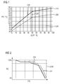
- FIG. 1 shows a diagrammatic representation of the course of the primary zone temperature TPZ (in ° C) as a function of the relative gas turbine power ⁇ GTP (in%).
- two fundamentally different operating modes of the gas turbine are shown, namely one with completely closed bypass flow channel (driving mode 200), and one with fully opened bypass flow channel (driving mode 210).
- driving mode 200 Driving mode 200
- driving mode 210 Driving mode 210
- Clearly recognizable in both driving modes 200 and 210 is a flatter course in the region of Leitschaufelverstell Schemes LSVB, via which the gas turbine can be operated at conventional partial load operation by suitable adjustment of the guide vanes in the Leitschaufelverstell Scheme LSVB at different partial load outputs.
- the areas accessible to the invention preferably relate to these underlying areas. As a result, they lie between the region 200 when the bypass flow channel is closed and the region 210, which represents a procedure with an open bypass flow channel.
- FIG. 1 two points 220, 230 are shown, which serve to illustrate further operating points.
- the operating point 220 represents a operating state with a minimum vane adjustment range which, when the bypass flow channel is partially open, reaches the primary zone temperature TPZ, as is the case for base load.
- the operating point 230 represents an operating state, which also reaches the primary zone temperature TPZ at base load, but this with fully open bypass flow channel.
- the operating point 230 is well below the technically possible minimum vane adjustment range LSVB in terms of relative gas turbine power.
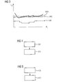
- FIG. 2 represents the functional profile of the relative opening cross section RQ as a function of the corrected turbine outlet temperature OTC.
- the relative opening cross section RQ relates to the ratio of the present, ie adjusted, opening cross section Q to the maximum possible opening cross section.
- the illustrated mode of operation below the Leitschaufelverstell Schemes LSVB on a travel curve, which has a plurality of nodes.
- a driving mode is initially selected during a first time period ZA1, which corresponds to an embodiment according to claim 1.
- the adjustment of the opening cross section Q of the bypass flow passage 10 is made such that the rate of change V of the opening area Q is selected such that the primary zone temperature TPZ is substantially constant, and in particular varies by not more than 10%.
- the rate of change V of the opening area Q is selected such that the primary zone temperature TPZ is substantially constant, and in particular varies by not more than 10%.
- the driving style is changed insofar as it now takes place according to an embodiment according to claim 2.
- the adjustment of the opening cross section Q of the bypass flow passage 10 is made such that the rate of change V of the opening area Q is selected such that the relative combustion chamber pressure loss ⁇ BDV or Material temperature MT of the combustion chamber 4 is substantially constant, in particular such that the relative combustion chamber pressure loss .DELTA.BDV or the material temperature MT of the combustion chamber 4 does not vary more than by 10%.
- Corrected turbine outlet temperature OTC corresponds to the turbine outlet temperature corrected in relation to the air temperature, as described, for example, in US Pat EP 1 462 633 A1 explained in detail.
- FIG. 3 shows a partial load reduction occurring change of the second thermal characteristic TK2 as a function of time.
- the partial load reduction also results in a reduction of the second thermal characteristic TK2.
- a predetermined second limit value GW2 is exceeded, however, the change in the cross-section Q of the bypass flow channel 10 is selected such that the opening cross-section Q is now reduced, in particular reduced stepwise.
- the gradual reduction is indicated here by the change behavior .DELTA.Q of the opening cross-section Q.
- FIG. 6 shows a perspective partial sectional view through a gas turbine 100 according to the invention, which substantially corresponds to the marketed by the applicant model SGT5-2000E.
- the gas turbine 100 has, in addition to a compressor 1 and an expansion turbine 5, a combustion chamber 4 provided with a plurality of burners 3.
- compressor air 2 is conveyed from the compressor 1 laterally on the outside of the combustion chamber 4 to the burners 3. Due to the static pressure difference between the combustion chamber 4 and the pressure of the compressor air 2 conducted on the outside of the combustion chamber 4, cooling air taken from this compressor air 2 flows through cooling channels 7 into the combustion chamber 4.
- the remaining compressor air 2 is supplied to the burners 3 and burnt with suitable fuel ,
- the combustion products are derived as hot gas stream 6 from the combustion chamber 4 and fed to the expansion turbine 5 for mechanical work.
- the gas turbine engine 100 shown has a bypass flow passage 10, not shown in detail, which is designed to supply compressor air 2 past the burner 3 and to a hot gas flow 6 generated in the combustion chamber 4 during operation of the gas turbine 100, wherein the opening cross section Q of the bypass flow channel 10 can be adjusted by an adjusting means 11. Also, this adjusting means 11 is not shown in detail here.
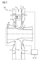
- FIG. 7 shows a schematic sectional view through the in FIG. 6 shown embodiment of the gas turbine 100, which represents both the bypass flow channels 10 and the adjusting means 11 for adjusting the opening cross-section Q of the bypass flow channel 10.
- compressor air 2 is first supplied from a compressor 1 (not further shown) to the combustion chamber 4.
- the compressor air 2 is in this case in a volume between the Combustion chamber 4 and an outer wall 8 to the burners 3 passed.
- the compressor air 2 flows past the bypass flow channel 10, which has an opening cross-section Q and connects the area between the combustion chamber 4 and the outer wall 8 with the combustion chamber 4 itself fluidically.
- the opening cross-section Q is adjustable by a trained as adjusting means slide 11 (more detailed information on this technology can from the DE 43 39 724 C1 be removed).
- the flow of the compressor air 2 is thus divided at the opening cross-section Q, wherein a part continues to flow to the burners 3 of the combustion chamber 4, another part but through the opening cross-section Q into the combustion chamber 4 for pressure equalization.
- the guided to the burners 3 stream of compressor air 2 is also reduced by the fact that a portion of this compressor air 2 can flow through not shown cooling channels 7 in the combustion chamber 4 and not shown here hot gas components, in particular the flame tube bottoms, the combustion chamber 4 cools.
- the cooling capacity is proportional to the voltage applied to the cooling channels static pressure difference.
- the gas turbine 100 has an adjustment unit 20, which comprises a control circuit 30, which is designed for the suitable adjustment of the opening cross-section Q of the bypass flow channel 10.
- the gas turbine 100 likewise has a measuring probe 40 which metrologically records a thermal characteristic (for example the turbine outlet temperature) and transmits the measured values to the setting unit 20 or the control circuit 30.
- the gas turbine 100 likewise has a second measuring probe 50 arranged in the combustion chamber 4, which is designed to metrologically detect the material temperature MT of the combustion chamber 4 and to transmit the measured values to the setting unit 20 or to the control circuit 30.
- the adjustment unit 20 ensures that the opening cross-section Q of the bypass flow passage 10 is set such that the rate of change V of the opening cross-section Q is selected such that the primary zone temperature TPZ is substantially constant, and in particular varies by not more than 10%, or that the rate of change V of the opening cross-section Q is chosen such that the relative combustion chamber pressure loss ⁇ BDV the material temperature MT of the combustion chamber 4 is substantially constant, in particular that the relative combustion chamber pressure loss ⁇ BDV the material temperature MT of the combustion chamber 4 does not vary more than 10%.
Landscapes
- Engineering & Computer Science (AREA)
- Chemical & Material Sciences (AREA)
- Combustion & Propulsion (AREA)
- Mechanical Engineering (AREA)
- General Engineering & Computer Science (AREA)
- Physics & Mathematics (AREA)
- Fluid Mechanics (AREA)
- Control Of Turbines (AREA)
Abstract
Die Erfindung betrifft eine Gasturbine (100) sowie geeignete Betriebsverfahren, wobei die Gasturbine 1 (100) einen Verdichter (1) zur Bereitstellung von Verdichterluft (2), eine mit einem Brenner (3) versehene Brennkammer (4) und eine Entspannungsturbine (5) aufweist, wobei weiterhin ein Bypass-Strömungskanal (10) vorgesehen ist, der dazu ausgebildet ist, bei Betrieb der Gasturbine (100) Verdichterluft (2) an dem Brenner (3) vorbei und einem in der Brennkammer (4) erzeugten Heißgasstrom (6) zuzuführen, und wobei weiterhin der Öffnungsquerschnitt (Q) des Bypass-Strömungskanals (10) durch ein Stellmittel (11) eingestellt werden kann, und wobei weiterhin eine Einstelleinheit (20) umfasst ist, welche dazu ausgebildet ist, den Öffnungsquerschnitt (Q) des Bypass-Strömungskanals (10) derart einzustellen, dass die Änderungsgeschwindigkeit (V) des Öffnungsquerschnitts (Q) derart gewählt ist, dass die Primärzonentemperatur (TPZ) im Wesentlichen konstant ist, und insbesondere nicht mehr als um 10% variiert, oder dass die Änderungsgeschwindigkeit des Öffnungsquerschnitts (Q) derart gewählt ist, dass der relative Brennkammerdruckverlust (BDV) oder eine Materialtemperatur (MT) der Brennkammer (4) im Wesentlichen konstant ist, insbesondere dass der relative Brennkammerdruckverlust (BDV) oder die Materialtemperatur (MT) der Brennkammer (4) nicht mehr als um 10% variiert.The invention relates to a gas turbine (100) and suitable operating methods, wherein the gas turbine 1 (100) has a compressor (1) for providing compressor air (2), a combustion chamber (4) provided with a burner (3) and an expansion turbine (5), wherein a bypass flow channel (10) is also provided, which is designed to supply compressor air (2) past the burner (3) and to a hot gas flow (6) generated in the combustion chamber (4) during operation of the gas turbine (100), and wherein the opening cross section (Q) of the bypass flow channel (10) can be adjusted by an adjusting means (11), and wherein an adjusting unit (20) is also included, which is designed to adjust the opening cross section (Q) of the bypass flow channel (10) such that the rate of change (V) of the opening cross section (Q) is selected such that the Primary zone temperature (TPZ) is essentially constant, and in particular does not vary by more than 10%, or that the rate of change of the opening cross section (Q) is selected such that the relative combustion chamber pressure loss (BDV) or a material temperature (MT) of the combustion chamber (4) is essentially constant, in particular that the relative combustion chamber pressure loss (BDV) or the material temperature (MT) of the combustion chamber (4) does not vary by more than 10%.
Description
Die vorliegende Erfindung betrifft ein Verfahren zum Betreiben einer Gasturbine in Teillast, die einen Verdichter zur Bereitstellung von Verdichterluft aufweist, eine mit einem Brenner versehene Brennkammer und eine Entspannungsturbine, wobei weiterhin ein Bypass-Strömungskanal vorgesehen ist, der dazu ausgebildet ist, bei Betrieb der Gasturbine Verdichterluft an dem Brenner vorbei und einem in der Brennkammer erzeugten Heißgasstrom zuzuführen. Ebenfalls betrifft die vorliegende Erfindung eine derartige Gasturbine.The present invention relates to a method of operating a part-load gas turbine having a compressor air compressor, a combustion chamber provided with a burner, and an expansion turbine, further comprising a bypass flow passage configured to operate the gas turbine Compressor air past the burner and supply a hot gas flow generated in the combustion chamber. Likewise, the present invention relates to such a gas turbine.
Gasturbinen sind typischerweise in ihrem Leistungsbereich zu den niedrigeren Teillastbereichen hin nur beschränkt betreibbar aufgrund von Grenzwertanforderungen an die CO-Emissionsmengen. Bei Verringerung des Teillastbetriebs zu kleineren Leistungen hin nimmt nämlich typischerweise die Primärzonentemperatur der Verbrennung zunehmend ab. Unterschreitet diese Primärzonentemperatur für eine Gasturbine typische Temperaturgrenzwerte, steigt die Menge an CO-Emissionen mitunter exponentiell an, da die Verbrennung von CO zu CO2 nicht mehr in ausreichendem Maße erfolgen kann. Bei Erreichen vorbestimmter Grenzwerte muss deshalb der Teillastbetrieb zu kleineren Leistungen hin eingeschränkt werden, um nicht gegen die CO-Emissionsgrenzwerte zu verstoßen. Eine solche Einschränkung wirkt sich ebenfalls auf den Betrieb einer mit einer solchen Gasturbine gekoppelten Dampfturbinenanlage (im Sinne einer Gas-und-Dampfkraftwerksanlage, GuD) aus, da eine vom Betreiber möglicherweise gewünschte Leistungsverminderung unterhalb eines Grenzwertes nicht zu erreichen sein wird.Gas turbines are typically limited in their power range to the lower part load ranges due to limit requirements on CO emission levels. Namely, as the partial load operation decreases to lower powers, the primary zone temperature of combustion typically decreases. If this primary zone temperature for a gas turbine falls below typical temperature limits, the amount of CO emissions sometimes increases exponentially, since the combustion of CO to CO 2 can no longer be carried out sufficiently. When predetermined limit values are reached, therefore, the partial load operation must be restricted to lower powers so as not to violate the CO emission limit values. Such a restriction also affects the operation of a coupled with such a gas turbine steam turbine plant (in the sense of a gas and steam power plant, CCG), as a possibly desired by the operator performance reduction below a threshold will not be achieved.
Aufgrund der Einhaltung vorbestimmter CO-Emissionsgrenzwerte ist also ein Kraftwerksbetreiber gezwungen, die Gasturbine bzw. eine mit dieser Gasturbine gekoppelte Dampfkraftwerksanlage zeitweise abzuschalten oder bei einem Teillastbereich zu verharren, der oberhalb der technisch möglichen Minimalleistung liegt.Due to compliance with predetermined CO emission limits so a power plant operator is forced to the gas turbine or a coupled with this gas turbine steam power plant temporarily shut down or to remain at a partial load range, which is above the technically possible minimum power.
Folglich stellt es sich als technisches Erfordernis dar, eine Gasturbine vorzuschlagen, bzw. ein Verfahren zum Betreiben einer solchen Gasturbine, welche erlauben, den Teillastbereich weiterhin nach unten abzusenken, ohne gleichzeitig CO-Emissionsgrenzwerte zu überschreiten. In anderen Worten soll also der Teillastbereich der Gasturbine unter Einhaltung von CO-Emissionsgrenzwerten insbesondere nach unten hin erweitert werden. Vor allem soll dieser Teillastbereich unterhalb des ansonsten technisch zugänglichen Lastbereiches vorgesehen sein, welcher durch geeignete Leitschaufelverstellung erreicht werden kann (sog. Leitschaufelverstellbereich).Consequently, it is a technical requirement to propose a gas turbine, or a method of operating such a gas turbine, which allow the part-load range to continue to lower down without simultaneously exceeding CO emission limits. In other words, therefore, the partial load range of the gas turbine should be extended in compliance with CO emission limits, in particular downwards. Above all, this part-load range should be provided below the otherwise technically accessible load range, which can be achieved by suitable guide vane adjustment (so-called Leitschaufelverstellbereich).
Die der Erfindung zugrundeliegenden Aufgaben werden gelöst durch ein Verfahren zum Betreiben einer solchen vorab wie auch nachfolgend beschriebenen Gasturbine gemäß Anspruch 1 sowie gemäß Anspruch 2, sowie durch eine nachfolgend beschriebene Gasturbine gemäß Anspruch 8.The objects underlying the invention are achieved by a method for operating such a gas turbine as described above in advance and also according to claim 1 and according to
Insbesondere werden die der Erfindung zugrundeliegenden Aufgaben gelöst durch ein Verfahren zum Betreiben einer Gasturbine in Teillast, welche einen Verdichter zur Bereitstellung von Verdichterluft, eine mit einem Brenner versehene Brennkammer und eine Entspannungsturbine aufweist, wobei weiterhin ein Bypass-Strömungskanal vorgesehen ist, der dazu ausgebildet ist, bei Betrieb der Gasturbine Verdichterluft an dem Brenner vorbei und einem in der Brennkammer erzeugten Heißgasstrom zuzuführen, und wobei weiterhin der Öffnungsquerschnitt des Bypass-Strömungskanals durch ein Stellmittel eingestellt werden kann, welches Verfahren folgende Schritte aufweist:
- Betreiben der Gasturbine in Teillast;
- Einstellung des Öffnungsquerschnitts des Bypass-Strömungskanals, so dass die Änderungsgeschwindigkeit des Öffnungsquerschnitts derart gewählt ist, dass die Primärzonentemperatur im Wesentlichen konstant ist, und insbesondere nicht mehr als um 10% variiert.
- Operating the gas turbine at part load;
- Adjustment of the opening cross section of the bypass flow channel, so that the rate of change of the opening cross-section is selected such that the Primary zone temperature is substantially constant, and in particular not more than 10% varied.
Weiterhin werden die der Erfindung zugrundeliegenden Aufgaben gelöst durch ein Verfahren zum Betreiben einer Gasturbine in Teillast, welche einen Verdichter zur Bereitstellung von Verdichterluft, eine mit einem Brenner versehene Brennkammer und eine Entspannungsturbine aufweist, wobei weiterhin ein Bypass-Strömungskanal vorgesehen ist, der dazu ausgebildet ist, bei Betrieb der Gasturbine Verdichterluft an dem Brenner vorbei und einem in der Brennkammer erzeugten Heißgasstrom zuzuführen, und wobei weiterhin der Öffnungsquerschnitt des Bypass-Strömungskanals durch ein Stellmittel eingestellt werden kann, welches Verfahren folgende Schritte aufweist:
- Betreiben der Gasturbine in Teillast;
- Einstellung des Öffnungsquerschnitts des Bypass-Strömungskanals, so dass die Änderungsgeschwindigkeit des Öffnungsquerschnitts derart gewählt ist, dass der relative Brennkammerdruckverlust oder eine Materialtemperatur der Brennkammer im Wesentlichen konstant ist, insbesondere, dass der relative Brennkammerdruckverlust oder die Materialtemperatur der Brennkammer nicht mehr als um 10% variiert.
- Operating the gas turbine at part load;
- Adjusting the opening area of the bypass flow passage so that the rate of change of the opening area is selected such that the relative combustion chamber pressure loss or a material temperature of the combustion chamber is substantially constant, in particular that the relative combustion chamber pressure loss or the material temperature of the combustion chamber does not vary more than 10% ,
Weiterhin werden die der Erfindung zugrundeliegenden Aufgaben gelöst durch eine Gasturbine geeignet zum Ausführen eines Verfahrens wie vorab und auch nachfolgend dargestellt, welche einen Verdichter zur Bereitstellung von Verdichterluft, eine mit einem Brenner versehene Brennkammer und eine Entspannungsturbine aufweist, wobei weiterhin ein Bypass-Strömungskanal vorgesehen ist, der dazu ausgebildet ist, bei Betrieb der Gasturbine Verdichterluft an dem Brenner vorbei und einem in der Brennkammer erzeugten Heißgasstrom zuzuführen, und wobei weiterhin der Öffnungsquerschnitt des Bypass-Strömungskanals durch ein Stellmittel eingestellt werden kann, wobei weiterhin eine Einstelleinheit umfasst ist, welche dazu ausgebildet ist, den Öffnungsquerschnitt des Bypass-Strömungskanals derart einzustellen, dass die Änderungsgeschwindigkeit des Öffnungsquerschnitts derart gewählt ist, dass die Primärzonentemperatur im Wesentlichen konstant ist, und insbesondere nicht mehr als um 10% variiert, oder dass die Änderungsgeschwindigkeit des Öffnungsquerschnitts derart gewählt ist, dass der relative Brennkammerdruckverlust oder die Materialtemperatur der Brennkammer im Wesentlichen konstant ist, insbesondere dass der relative Brennkammerdruckverlust nicht mehr als um 10% variiert.Furthermore, the objects underlying the invention are achieved by a gas turbine suitable for carrying out a method as previously and also shown below, which has a compressor for providing compressor air, a combustion chamber provided with a burner and an expansion turbine, wherein a bypass flow channel is further provided adapted to supply compressor air past the burner and to a hot gas flow generated in the combustion chamber during operation of the gas turbine, and further wherein the opening cross section of the bypass flow channel can be adjusted by an adjusting means, further comprising a setting unit, which is adapted is, the opening cross section of the bypass flow channel such that the rate of change of the opening cross section is selected such that the primary zone temperature is substantially constant, and in particular varies no more than 10%, or that the rate of change of the opening cross section is such that the relative combustion chamber pressure loss or the material temperature of the combustion chamber in Is substantially constant, in particular that the relative combustion chamber pressure loss does not vary more than by 10%.
Die Einstelleinheit ist hierbei bevorzugt als Regeleinheit ausgebildet, kann jedoch auch als Steuereinheit ausgebildet sein. Die Einstelleinheit ermöglicht hierbei die automatische Einstellung der Änderungsgeschwindigkeit des Öffnungsquerschnitts, bzw. des Öffnungsquerschnitts.The adjustment unit is preferably designed as a control unit, but may also be designed as a control unit. The setting unit allows the automatic adjustment of the rate of change of the opening cross section, or of the opening cross section.
An dieser Stelle sei darauf hingewiesen, dass die Primärzonentemperatur (TPZ) eine aus der Energiebilanz um Brenner und Flamme ermittelte Mitteltemperatur ist, die den thermodynamischen Zustand des Heißgases nach abgeschlossener chemischer Reaktion beschreibt. Die TPZ korreliert daher sehr gut mit dem CO-Anteil der Verbrennungsgase.It should be noted that the primary zone temperature (TPZ) is a mean temperature determined from the energy balance around burner and flame, which describes the thermodynamic state of the hot gas after completion of the chemical reaction. The TPZ correlates very well with the CO content of the combustion gases.
Weiterhin ist darauf hinzuweisen, dass der relative Brennkammerdruckverlust als Quotient aus Brennkammerdifferenzdruck und Verdichterenddruck ermittelt werden kann. Hierbei ergibt sich der Brennkammerdifferenzdruck durch eine Differenz zweier statischer Drücke, die an unterschiedlichen Messstellen an oder in der Brennkammer ermittelt werden. Typischerweise wird eine Druckermittlung vor dem Brenner bzw. im Bereich des Brenners ermittelt, und ein Druckwert innerhalb der Brennkammer, etwa am Ende der Verbrennungszone. Die Druckdifferenz aus beiden ermittelten Druckwerten wird durch Quotientenbildung auf den Verdichterenddruck bezogen, der, wie der Name bereits sagt, den statischen Druck am Ende des Verdichters beschreibt und ebenfalls messtechnisch erfassbar ist.It should also be pointed out that the relative combustion chamber pressure loss can be determined as the quotient of the combustion chamber differential pressure and the compressor discharge pressure. In this case, the combustion chamber differential pressure results from a difference between two static pressures, which are determined at different measuring points on or in the combustion chamber. Typically, a pressure determination in front of the burner or in the region of the burner is determined, and a pressure value within the combustion chamber, approximately at the end of the combustion zone. The pressure difference between the two determined pressure values is related by quotient formation to the compressor discharge pressure, which, as the name implies, describes the static pressure at the end of the compressor and can also be detected metrologically.
Ebenso soll darauf hingewiesen werden, dass die erfindungsgemäße Materialtemperatur der Brennkammer sich auf eine direkt und indirekt messtechnisch erfasste Materialtemperatur bezieht. Eine solche ist insbesondere eine Temperatur der Brennkammerwandung, eine Temperatur der Brennkammerkacheln, oder etwa eine Temperatur eines Flammrohrbauteils, welches von der Brennkammer mit umfasst ist.Likewise, it should be pointed out that the material temperature of the combustion chamber according to the invention relates to a directly and indirectly metrologically detected material temperature. Such is in particular a temperature of the combustion chamber wall, a temperature of the combustion chamber tiles, or about a temperature of a flame tube component, which is encompassed by the combustion chamber.
Das Vorsehen eines vorab beschriebenen Bypass-Strömungskanals in einer Gasturbine ist bereits aus dem Stand der Technik bekannt. So beschreibt bspw. die
An dieser Stelle sei darauf hingewiesen, dass die Offenbarung der
Die vorliegende Erfindung nutzt nun eine Einstellung des Öffnungsquerschnitts des Bypass-Strömungskanals, um bei einem Teillastbetrieb eine zu CO-Emissionsgrenzwerten konforme Fahrweise zu gewährleisten. Hierbei wird der Öffnungsquerschnitt des Bypass-Strömungskanals zeitlich verändert, so dass die Änderungsgeschwindigkeit des Öffnungsquerschnitts derart gewählt ist, dass die Primärzonentemperatur im Wesentlichen konstant ist. Bevorzugt bleibt die Primärzonentemperatur unterhalb des durch den Leitschaufelverstellbereich bestimmten Leistungsbereichs der Gasturbine im Wesentlichen konstant. Die Primärzonentemperatur liegt so etwa bei Erreichen des minimalen Leitschaufelverstellbereichs typischerweise immer noch oberhalb einer Temperatur, ab welcher mit einer deutlichen Erhöhung der CO-Emissionen zu rechnen ist. Geeignete Abschätzungen dieser Temperatur sind aus dem Stand der Technik bekannt, bzw. sind für eine konkrete Ausführungsform der Gasturbine numerisch leicht ermittelbar.The present invention now utilizes adjustment of the opening cross-section of the bypass flow passage to conform to CO emission limits in a part-load operation To ensure driving style. Here, the opening cross section of the bypass flow channel is changed over time, so that the rate of change of the opening cross-section is selected such that the primary zone temperature is substantially constant. The primary zone temperature preferably remains substantially constant below the power range of the gas turbine determined by the guide vane adjustment range. The primary zone temperature, for example, when the minimum vane adjustment range is reached, is typically still above a temperature above which a significant increase in CO emissions is to be expected. Suitable estimates of this temperature are known from the prior art, or are numerically easily determined for a specific embodiment of the gas turbine.
Aufgrund solcher thermischer Abschätzungen bzw. geeigneter Rechenverfahren kann der Öffnungsquerschnitt des Bypass-Strömungskanals auch bei Teillastleitungen berechnet werden, die insbesondere unterhalb des durch den Leitschaufelverstellbereich bestimmten Leistungsbereichs der Gasturbine liegen, wobei etwa als Randbedingung eine im Wesentlichen konstante Primärzonentemperatur gewährleistet werden kann. Solche Abschätzungen bzw. Rechenverfahren können mitunter auch auf Versuchsmessungen basieren. Wird nun ein Teillastbetrieb zu kleineren Werten hin vermindert, erfolgt erfindungsgemäß eine kontinuierliche Einstellung des Öffnungsquerschnitts des Bypass-Strömungskanals zu größeren Werten hin, so dass ein zunehmender Druckausgleich zwischen dem stromabwärts angeordneten Bereich des Bypass-Strömungskanals (Brennkammer) und dem stromaufwärts angeordneten Bereich des Bypass-Strömungskanals (Verdichterluftplenum) resultiert.On the basis of such thermal estimates or suitable calculation methods, the opening cross section of the bypass flow channel can also be calculated for partial load lines, which are in particular below the power range of the gas turbine determined by the guide vane adjustment range, whereby an essentially constant primary zone temperature can be ensured as a boundary condition. Such estimates or calculation methods may sometimes also be based on experimental measurements. If a partial load operation is reduced to smaller values, a continuous adjustment of the opening cross section of the bypass flow channel to larger values occurs according to the invention, so that increasing pressure equalization between the downstream region of the bypass flow channel (combustion chamber) and the upstream region of the bypass Flow channel (Verdichterluftplenum) results.
Infolgedessen wird auch die Druckdifferenz vermindert, welche die Strömungsgeschwindigkeit der Verdichterluft durch den Brenner bestimmt. Gleichzeitig kann auch - variierend je nach Ausführungsform der Gasturbine - die Kühlleistung zur Brennkammerkühlung verändert werden, welche etwa aufgrund der Einströmung von Verdichterluft in Kühlkanäle der Brennkammer zur Kühlung von Heißgasteilen in der Brennkammer resultiert. An dieser Stelle ist insbesondere die Gasturbine des Typs SGT X-2000E der Anmelderin zu nennen, bei welcher derartige Kühlkanäle als Kühlluftbohrungen zur Kühlung der Flammrohrböden durch Prallkühlung vorgesehen sind (siehe etwa auch
Aufgrund der Verminderung des Drucks des der Brennkammer zugeführten Verdichterluftstroms kommt es ebenfalls zu einer Verringerung der Kühlleistung der Heißgasteile in der Brennkammer. Werden nun die thermischen Belastungen für die Heißgasteile der Brennkammer aufgrund der verminderten Kühlung zu groß, kann mit Materialschäden sowie dem Ausfall einzelner Bauteile zu rechnen sein. Um einer solchen Entwicklung vorzugreifen, wird nun erfindungsgemäß vorgeschlagen, eine Anpassung der Änderungsgeschwindigkeit des Öffnungsquerschnitts des Bypass-Strömungskanals vorzunehmen, und zwar derart, dass der relative Brennkammerdruckverlust oder eine Materialtemperatur der Brennkammer als Einstellgröße herangezogen wird. Durch einen im Wesentlichen konstanten relativen Brennkammerdruckverlust wird die Strömungsgeschwindigkeit der Verdichterluft zur Kühlung der Heißgasteile in der Brennkammer ebenfalls im Wesentlichen konstant gehalten. Damit resultiert eine im Wesentlichen konstante Kühlrate, so dass eine Erhöhung der Temperaturen, mit welchen die Heißgasteile in der Brennkammer beaufschlagt werden, vermieden werden kann.Due to the reduction in the pressure of the compressor air flow supplied to the combustion chamber, there is likewise a reduction in the cooling capacity of the hot gas components in the combustion chamber. Now, if the thermal loads on the hot gases of the combustion chamber due to the reduced cooling too large, can be expected to material damage and failure of individual components. In order to anticipate such a development, it is now proposed according to the invention to make an adjustment of the rate of change of the opening cross section of the bypass flow channel, in such a way that the relative combustion chamber pressure loss or a material temperature of the combustion chamber is used as a set value. By a substantially constant relative combustion chamber pressure loss, the flow velocity of the compressor air for cooling the hot gas components in the combustion chamber is also kept substantially constant. This results in a substantially constant cooling rate, so that an increase in the temperatures with which the hot gas components are acted upon in the combustion chamber, can be avoided.
Ausführungsgemäß wird vorgeschlagen, eine Gasturbine durch ein Verfahren gemäß Anspruch 1, insbesondere bei Verminderung der Teillast, zunächst so lange zu betreiben, bis die thermischen Belastungen für die Heißgasteile der Brennkammer zu groß werden. Anschließend kann vorgesehen sein, die Gasturbine durch ein Verfahren gemäß Anspruch 2 zu betreiben, so dass die resultierende Kühlleistung in der Brennkammer bzw. an den Heißgasteilen in der Brennkammer im Wesentlichen konstant ist. Ausführungsgemäß wird die Primärzonentemperatur zunächst als geeignete Einstellgröße herangezogen, wobei nach Erreichen eines nicht weiter zu überschreitenden Temperaturgrenzwerts der relative Brennkammerdruckverlust oder die Materialtemperatur der Brennkammer als weitere Einstellgröße herangezogen wird. Durch die kombinierte Fahrweise bzw. durch die jeweiligen Einzelfahrweisen nach Anspruch 1 und 2 ist gewährleistet, dass die CO-Emissionswerte im Wesentlichen konstant gehalten werden können, bzw. unterhalb vorbestimmter CO-Grenzwerte liegen.It is proposed according to the invention to initially operate a gas turbine by a method according to claim 1, in particular by reducing the partial load, until the thermal loads on the hot gas components of the combustion chamber become too great. Subsequently, it may be provided to operate the gas turbine by a method according to
Die Änderungsgeschwindigkeit des Öffnungsquerschnitts des Bypass-Strömungskanals wird also im Verlauf des Teillastbetriebs derart angepasst, dass auch eine Verringerung der Teillast unterhalb von anlagenspezifischen Grenzwerten (etwa bestimmt durch den Leitschaufelverstellbereich) ermöglicht werden kann.The rate of change of the opening cross section of the bypass flow channel is thus adjusted in the course of the partial load operation such that a reduction of the partial load below plant-specific limits (such as determined by the Leitschaufelverstellbereich) can be made possible.
Erfindungsgemäß ist es möglich, die Änderung des Öffnungsquerschnitts des Bypass-Strömungskanals als eine kontinuierliche und/oder eine schrittweise Änderung über die Zeit hinweg auszuführen, wobei die jeweiligen Änderungen derart ausgeführt werden, dass die zugrundeliegenden Einstellgrößen (Primärzonentemperatur bzw. relativer Brennkammerdruckverlust) im Wesentlichen konstant bleiben, insbesondere aber nicht um mehr als 10% variieren. Die jeweils auszuführenden Änderungen können im Falle einer diskreten Änderung im Sinne von Stützstellen in einer Einstelleinheit hinterlegt sein, die dann bei Bedarf eine geeignete Änderung des Öffnungsquerschnitts veranlasst werden. Die Änderungsgeschwindigkeit des Öffnungsquerschnitts ist hierbei als zeitliches Mittel über die einzelnen diskreten Stützstellen zu verstehen.According to the invention, it is possible to carry out the change of the opening cross section of the bypass flow channel as a continuous and / or a stepwise change over time, wherein the respective changes are carried out such that the underlying adjustment variables (primary zone temperature or relative combustion chamber pressure loss) are substantially constant stay, but in particular do not vary more than 10%. The changes to be carried out in each case can be stored in a setting unit in the case of a discrete change in the sense of interpolation points, which then, if required, causes a suitable change in the opening cross section. The rate of change of the opening cross-section is to be understood here as a time average over the individual discrete interpolation points.
Gemäß einer ersten und besonders bevorzugten Ausführungsform des erfindungsgemäßen Verfahrens ist vorgesehen, dass während eines ersten Zeitabschnitts das Verfahren nach Anspruch 1 ausgeführt wird, und während eines zweiten Zeitabschnitts das Verfahren nach Anspruch 2, wobei insbesondere der zweite Zeitabschnitt unmittelbar an den ersten Zeitabschnitt anschließt. Wie bereits oben im Detail erklärt, kann so eine besonders effiziente Fahrweise der Gasturbine in Teillast erreicht werden, die auch bei sehr geringen Teillastbereichen einen CO-konformen Betrieb ermöglicht. Ausführungsgemäß ist besonders bevorzugt, dass hierbei die Teillast über die Zeitabschnitte hinweg vermindert, insbesondere über beide Zeitabschnitte hinweg vermindert wird.According to a first and particularly preferred embodiment of the method according to the invention, it is provided that the method according to claim 1 is carried out during a first time period, and the method according to
Gemäß einer weiteren Ausführungsform des erfindungsgemäßen Verfahrens ist vorgesehen, dass das Verfahren nach Anspruch 1 während eines ersten Zeitabschnitts solange ausgeführt wird, bis eine erste thermische Kenngröße einen vorbestimmten ersten Grenzwert erreicht, wobei dann insbesondere der zweite Zeitabschnitt anschließt, während dessen ein Verfahren nach Anspruch 2 ausgeführt wird. Die erste thermische Kenngröße ist hierbei insbesondere ein Maß für die Kühlleistung an Heißgasteilen der Brennkammer. Insofern kann bei Überschreiten eines thermischen Grenzwertes (erster Grenzwert) ein sicherer Betrieb der Gasturbine auch bei noch geringeren Teillastleistungen als während des ersten Zeitabschnitts erreicht werden, ohne CO-Emissionsgrenzwerte zu überschreiten.According to a further embodiment of the method according to the invention, it is provided that the method according to claim 1 is carried out during a first time period until a first thermal characteristic reaches a predetermined first threshold, in which case the second period is followed, during which a method according to
Gemäß eines weiteren besonders bevorzugten Verfahrens ist vorgesehen, dass das Verfahren nach Anspruch 2 so lange bei einer Teillastverminderung ausgeführt wird, bis eine zweite thermische Kenngröße einen vorbestimmten zweiten Grenzwert erreicht, wobei dann insbesondere die Änderung des Öffnungsquerschnitts derart gewählt wird, dass der Öffnungsquerschnitt verringert wird, insbesondere schrittweise verringert wird. Eine solche verfahrenstechnische Vorkehrung kann mitunter erforderlich sein, da der relative Brennkammerdruckverlust von den Umgebungsbedingungen abhängig ist, und somit nicht stets eine ausreichende Kühlleistung der Heißgasteile der Brennkammer gewährleistet werden kann, wenn etwa die Umgebungstemperaturen sehr hoch sind. Wird nun trotz kontinuierlicher bzw. schrittweiser Vergrößerung des Öffnungsquerschnitts des Bypass-Strömungskanals keine ausreichende Kühlleistung zur Verfügung gestellt, kann ein zweiter Grenzwert einer zweiten thermischen Kenngröße überschritten werden. Die thermische Kenngröße ist insbesondere eine geeignete Einstellgröße, die die Temperaturbelastung in der Brennkammer erfasst, und damit den thermisch sicheren Betrieb der Gasturbine gewährleistet. Eine geeignete Kenngröße für diese Temperaturbelastung kann bspw. etwa eine gemessene Materialtemperatur (bevorzugt in der Brennkammer) sein, die über ein Thermoelement direkt oder indirekt erfasst wurde, bzw. eine Ersatzkenngröße, wie bspw. der relative Brennkammerdruckverlust oder andere geeignete thermische Größe.According to a further particularly preferred method, it is provided that the method according to
Wird nun der zweite Grenzwert durch die zweite thermische Kenngröße erreicht, wird der Öffnungsquerschnitt des Bypass-Strömungskanals verringert. Bevorzugt erfolgt diese Verringerung in Schrittweiten von etwa 10 % des gesamten Verfahrwegs. Infolgedessen steigt der Kühlluftmassenstrom erneut an und die Heißgasteile der Brennkammer werden verstärkt mit Kühlleistung versorgt. Ausführungsgemäß kann dieser Vorgang insbesondere bei schrittweiser Änderung so lange wiederholt werden, bis die zweite thermische Kenngröße einen Wert oberhalb eines weiteren dritten thermischen Grenzwertes erreicht.If now the second limit value is reached by the second thermal characteristic, the opening cross-section of the bypass flow channel is reduced. Preferably, this reduction is done in increments of about 10% of the total travel. As a result, the cooling air mass flow increases again and the hot gases of the combustion chamber are increasingly supplied with cooling power. According to the embodiment, this process can be repeated until the second thermal parameter reaches a value above a further third thermal limit value, in particular in the case of a stepwise change.
Entsprechend einer Weiterführung des ausführungsgemäßen Verfahrens ist vorgesehen, dass bei Verringerung des Öffnungsquerschnittes und bei Erreichen eines dritten thermischen vorbestimmten Grenzwertes durch die zweite thermische Kenngröße die Änderung des Öffnungsquerschnitts derart gewählt wird, dass der Öffnungsquerschnitt wieder vergrößert wird, insbesondere wieder schrittweise vergrößert wird. Eine schrittweise Vergrößerung kann hierbei bevorzugt in Schritten von etwa 10 % des gesamten Verfahrwegs erfolgen. Durch die so ausgeführte Hysterese einer Verkleinerung zunächst und dann wieder darauf erfolgenden Vergrößerung des Öffnungsquerschnittes des Bypass-Strömungskanals kann eine stabile Regelung des Gasturbinenbetriebs erreicht werden.According to a continuation of the method according to the invention, it is provided that when the opening cross section is reduced and a third thermal predetermined limit value is reached, the change in the opening cross section is selected such that the opening cross section is increased again, in particular gradually increased again. A stepwise enlargement can in this case preferably take place in steps of approximately 10% of the total travel path. Due to the hysteresis of a reduction in this way and then again enlargement of the opening cross section of the bypass flow channel, a stable regulation of the gas turbine operation can be achieved.
Gemäß einer besonders bevorzugten Ausführungsform des erfindungsgemäßen Verfahrens ist vorgesehen, dass das Verfahren unterhalb des Leitschaufelverstellbereiches ausgeführt wird. Infolgedessen kann wie oben erklärt, der Teillastleistungsbereich weiter verringert werden, ohne jedoch eine Überschreitung von CO-Grenzwerten befürchten zu müssen. Damit kann die Flexibilisierung des Gasturbinenbetriebs signifikant verbessert werden.According to a particularly preferred embodiment of the method according to the invention, it is provided that the method is carried out below the Leitschaufelverstellbereiches. As a result, as explained above, the part-load power range be further reduced, but without fear of exceeding CO limits. Thus, the flexibility of the gas turbine operation can be significantly improved.
Gemäß einer ersten besonders bevorzugten Ausführungsform der erfindungsgemäßen Gasturbine ist vorgesehen, dass weiterhin eine Regelschaltung und eine Messsonde umfasst sind, wobei die Messsonde zur Erfassung einer thermischen Kenngröße ausgebildet ist und die Regelschaltung dazu ausgebildet ist, bei einer Teillastverminderung bei Erreichen eines vorbestimmten Grenzwertes (zweiter Grenzwert) der thermischen Kenngröße (zweite thermische Kenngröße), die Änderung des Öffnungsquerschnittes derart gewählt wird, dass der Öffnungsquerschnitt wieder verringert wird, insbesondere schrittweise verringert wird.According to a first particularly preferred embodiment of the gas turbine according to the invention, it is further provided that a control circuit and a measuring probe are included, wherein the measuring probe is designed to detect a thermal characteristic and the control circuit is adapted to a partial load reduction upon reaching a predetermined limit value (second limit ) of the thermal characteristic (second thermal characteristic), the change in the opening cross-section is chosen such that the opening cross-section is reduced again, in particular, is gradually reduced.
Wie weiter oben bereits ausgeführt, kann so eine stabile Regelung der Gasturbine erreicht werden, wobei gleichzeitig der Abhängigkeit des relativen Brennkammerdruckverlustes von den Umgebungsbedingungen Rechnung getragen werden kann. Ebenfalls kann gleichzeitig der Schutz von Heißgasteilen der Brennkammer durch ausreichende Kühlung gewährleistet werden.As already stated above, such a stable control of the gas turbine can be achieved, whereby at the same time the dependence of the relative combustion chamber pressure loss on the ambient conditions can be taken into account. At the same time the protection of hot gas parts of the combustion chamber can be ensured by adequate cooling.
Gemäß einer weiteren besonders bevorzugten Ausführungsform der erfindungsgemäßen Gasturbine ist vorgesehen, dass die Gasturbine derart ausgebildet ist, dass die dem Brenner zugeleitete Verdichterluft wenigstens zum Teil zum Kühlen von Heißgasteilen der Brennkammer, insbesondere von Flammrohrböden, mittels Leitung durch Kühlkanäle in der Brennkammer vorgesehen ist. Durch das Vorsehen von Kühlkanälen in der Brennkammer kann insbesondere bei Ausführung des Verfahrens nach Anspruch 2 eine ausreichende Kühlleistung gewährleistet werden. Damit kann einer Überhitzung und einer daraus folgenden Schädigung von Heißgasteilen der Brennkammer vorgebeugt werden.According to a further particularly preferred embodiment of the gas turbine according to the invention it is provided that the gas turbine is designed such that the compressor air supplied to the burner is provided at least in part for cooling hot gas parts of the combustion chamber, in particular of flame tube floors, by means of conduit through cooling channels in the combustion chamber. By providing cooling channels in the combustion chamber, a sufficient cooling capacity can be ensured, in particular when the method according to
Nachfolgend soll die Erfindung anhand einzelner Figuren im Detail näher beschrieben werden. Hierbei sei darauf hingewiesen, dass technische Merkmale, die gleiche Bezugszeichen aufweisen, gleiche technische Wirkungen aufweisen.The invention will be described in more detail below with reference to individual figures. It should be noted that technical features that have the same reference numerals have the same technical effects.
Ebenfalls soll darauf hingewiesen sein, dass die nachfolgenden Figuren lediglich schematisch zu verstehen sind, und damit keine Einschränkung hinsichtlich der Ausführbarkeit der Erfindung begründet werden kann.It should also be pointed out that the following figures are only to be understood schematically, and that no restriction with regard to the practicability of the invention can be justified.
Ebenfalls ist zu bemerken, dass die nachfolgend erklärten technischen Merkmale in beliebiger Kombination miteinander beansprucht werden, soweit die Kombination, die die der Erfindung zugrundeliegende Aufgabe lösen kann.It should also be noted that the technical features explained below are claimed in any combination with each other, as far as the combination that can solve the problem underlying the invention.
Hierbei zeigen:
- Figur 1
- eine schematische Darstellung der Änderung der Primärzonentemperatur (TPZ) in Abhängigkeit von der relativen Gasturbinenleistung (ΔGTP) bei vollständig geschlossenem und offenem Öffnungsquerschnitt des Bypass-Strömungskanals;
Figur 2- eine diagrammatische Darstellung des relativen Öffnungsquerschnitts (RQ) in Abhängigkeit von der korrigierten Turbinenaustrittstemperatur (OTC) unterhalb des Leitschaufelverstellbereichs (LSVB) entsprechend geeigneter Ausführungsformen der erfindungsgemäßen Fahrweisen in Teillast;
- Figur 3
- einen funktionalen Verlauf der zweiten thermischen Kenngröße (TK2) in Abhängigkeit von der Zeit (t) bei einem Betrieb zur Verminderung der Teillastleistung bei Erreichen eines zweiten Grenzwertes (GW2) sowie eines dritten Grenzwertes (GW3);
Figur 4- eine erste Ausführungsform des erfindungsgemäßen Verfahrens nach Anspruch 1;
Figur 5- eine weitere Ausführungsform des erfindungsgemäßen Verfahrens nach Anspruch 2;
Figur 6- eine Ausführungsform einer erfindungsgemäßen Gasturbine in perspektivischer seitlicher Schnittansicht;
- Figur 7
- eine vereinfachte schematische Teilschnittansicht der in
Figur 6
- FIG. 1
- a schematic representation of the change in the primary zone temperature (TPZ) as a function of the relative gas turbine power (ΔGTP) with fully closed and open opening cross-section of the bypass flow channel;
- FIG. 2
- a diagrammatic representation of the relative opening cross section (RQ) as a function of the corrected turbine outlet temperature (OTC) below the Leitschaufelverstellbereichs (LSVB) according to suitable embodiments of the driving modes according to the invention in partial load;
- FIG. 3
- a functional course of the second thermal characteristic (TK2) as a function of time (t) in an operation for reducing the partial load power when a second limit value (GW2) and a third limit value (GW3) are reached;
- FIG. 4
- a first embodiment of the method according to claim 1;
- FIG. 5
- a further embodiment of the method according to
claim 2 according to the invention; - FIG. 6
- an embodiment of a gas turbine according to the invention in a perspective side sectional view;
- FIG. 7
- a simplified schematic partial sectional view of in
FIG. 6 shown gas turbine.
Beispielhaft sind in
Während eines zweiten Zeitabschnitts ZA2, welcher direkt an den ersten Zeitabschnitt ZA1 anschließt, wird die Fahrweise insofern geändert, als dass diese nun entsprechend einer Ausführungsform nach Anspruch 2 erfolgt. Hierbei wird bei der Gasturbine die Einstellung des Öffnungsquerschnitts Q des Bypass-Strömungskanals 10 so vorgenommen, dass die Änderungsgeschwindigkeit V des Öffnungsquerschnitts Q derart gewählt ist, dass der relative Brennkammerdruckverlust ΔBDV oder die Materialtemperatur MT der Brennkammer 4 im Wesentlichen konstant ist, insbesondere derart, dass der relative Brennkammerdruckverlust ΔBDV oder die Materialtemperatur MT der Brennkammer 4 nicht mehr als um 10% variiert. Gemäß dieser Fahrweise kann gewährleistet werden, dass auch bei Einhaltung der CO-Emissionsgrenzwerte weiterhin eine ausreichende Kühlleistung für Heißgasteile in der Brennkammer zur Verfügung steht und so eine thermische Beschädigung dieser Bauteile verhindert werden kann.During a second time period ZA2, which connects directly to the first time period ZA1, the driving style is changed insofar as it now takes place according to an embodiment according to
Die weiteren in der Darstellung gezeigten Stützstellen bzw. Betriebszustände, betreffen jeweils aus dem Stand der Technik bekannte bzw. nicht weiter zu erklärende Stützpunkte bzw. Betriebszustände.The further support points or operating states shown in the illustration relate in each case to interpolation points or operating states which are known from the prior art or can not be further explained.
Die in
Betreiben der Gasturbine 100 in Teillast (erster Verfahrensschritt 300);- Einstellung des Öffnungsquerschnitts Q des Bypass-
Strömungskanals 10, so dass die Änderungsgeschwindigkeit V des Öffnungsquerschnitts Q derart gewählt ist, dass die Primärzonentemperatur TPZ im Wesentlichen konstant ist, und insbesondere nicht mehr als um 10% variiert (zweiter Verfahrensschritt 310).
- Operating the
gas turbine 100 at partial load (first method step 300); - Adjustment of the opening cross-section Q of the
bypass flow channel 10, so that the rate of change V of the opening cross-section Q is selected such that the primary zone temperature TPZ is substantially constant, and in particular not more than 10% varied (second method step 310).
Betreiben der Gasturbine 100 in Teillast (erster Verfahrensschritt 400);- Einstellung des Öffnungsquerschnitts Q des Bypass-
Strömungskanals 10, so dass die Änderungsgeschwindigkeit V des Öffnungsquerschnitts Q derart gewählt ist, dass der relative Brennkammerdruckverlust ΔBDV oder die Materialtemperatur MT der Brennkammer 4 im Wesentlichen konstant ist, insbesondere dass der relative Brennkammerdruckverlust ΔBDV oder die Materialtemperatur MT der Brennkammer 4 nicht mehr als um 10% variiert (zweiter Verfahrensschritt 410).
- Operating the
gas turbine 100 at partial load (first method step 400); - Adjustment of the opening cross-section Q of the
bypass flow passage 10 so that the rate of change V of the opening cross-section Q is chosen such that the relative combustion chamber pressure loss ΔBDV or the material temperature MT of thecombustion chamber 4 is substantially constant, in particular that the relative combustion chamber pressure loss ΔBDV or the material temperature MT ofCombustion chamber 4 is not more than 10% varied (second step 410).
Die dargestellte Gasturbine 100 weist einen nicht weiter im Detail gezeigten Bypass-Strömungskanal 10 auf, der dazu ausgebildet ist, bei Betrieb der Gasturbine 100 Verdichterluft 2 an dem Brenner 3 vorbei und einem in der Brennkammer 4 erzeugten Heißgasstrom 6 zuzuführen, wobei weiterhin der Öffnungsquerschnitt Q des Bypass-Strömungskanals 10 durch ein Stellmittel 11 eingestellt werden kann. Auch dieses Stellmittel 11 ist vorliegend nicht im Detail gezeigt.The
Der zu den Brennern 3 geführte Strom an Verdichterluft 2 wird zudem dadurch vermindert, dass ein Teil dieser Verdichterluft 2 durch nicht weiter gezeigte Kühlkanäle 7 in die Brennkammer 4 einströmen kann und hierbei nicht weiter gezeigte Heißgasbauteile, insbesondere die Flammenrohrböden, der Brennkammer 4 kühlt. Die Kühlleistung ist hierbei proportional zur an den Kühlkanälen anliegenden statischen Druckdifferenz.The guided to the burners 3 stream of
Weiterhin weist die Gasturbine 100 eine Einstelleinheit 20 auf, die eine Regelschaltung 30 umfasst, die für die geeignete Einstellung des Öffnungsquerschnitts Q des Bypass-Strömungskanals 10 ausgebildet ist. Ebenfalls weist die Gasturbine 100 eine Messsonde 40 auf, welche eine thermische Kenngröße messtechnisch erfasst (bspw. die Turbinenaustrittstemperatur) und die Messwerte an die Einstelleinheit 20 bzw. die Regelschaltung 30 übermittelt. Ebenso weist die Gasturbine 100 eine in der Brennkammer 4 angeordnete zweite Messsonde 50 auf, welche dazu ausgebildet ist, die Materialtemperatur MT der Brennkammer 4 messtechnisch zu erfassen und die Messwerte an die Einstelleinheit 20 bzw. an die Regelschaltung 30 zu übermitteln. Die Einstelleinheit 20 gewährleistet, dass der Öffnungsquerschnitt Q des Bypass-Strömungskanals 10 derart eingestellt wird, dass die Änderungsgeschwindigkeit V des Öffnungsquerschnitts Q derart gewählt ist, dass die Primärzonentemperatur TPZ im Wesentlichen konstant ist, und insbesondere um nicht mehr als 10% variiert, oder dass die Änderungsgeschwindigkeit V des Öffnungsquerschnitts Q derart gewählt ist, dass der relative Brennkammerdruckverlust ΔBDV die Materialtemperatur MT der Brennkammer 4 im Wesentlichen konstant ist, insbesondere, dass der relative Brennkammerdruckverlust ΔBDV die Materialtemperatur MT der Brennkammer 4 nicht mehr als um 10% variiert.Furthermore, the
Weitere Ausführungsformen ergeben sich aus den Unteransprüchen.Further embodiments emerge from the subclaims.
Claims (10)
dadurch gekennzeichnet, dass während eines ersten Zeitabschnitts (ZA1) das Verfahren nach Anspruch 1 ausgeführt wird, und während eines zweiten Zeitabschnitts (ZA2) das Verfahren nach Anspruch 2, wobei insbesondere der zweite Zeitabschnitt (ZA2) unmittelbar an den ersten Zeitabschnitt (ZA1) anschließt.Method according to claims 1 and 2,
characterized in that during a first time period (ZA1) the method according to claim 1 is executed, and during a second time period (ZA2) the method according to claim 2, wherein in particular the second time period (ZA2) directly adjoins the first time period (ZA1) ,
dadurch gekennzeichnet, dass das Verfahren nach Anspruch 1 während eines ersten Zeitabschnitts (ZA1) solange ausgeführt wird, bis eine erste thermische Kenngröße (TK1) einen vorbestimmten ersten Grenzwert (GW1) erreicht, wobei dann insbesondere der zweite Zeitabschnitt (ZA2) anschließt, während dessen ein Verfahren nach Anspruch 2 ausgeführt wird.Method according to claim 1 and 2 or 3,
characterized in that the method according to claim 1 during a first time period (ZA1) is executed until a first thermal characteristic (TK1) reaches a predetermined first limit value (GW1), then in particular the second time period (ZA2) connects, during which a method according to claim 2 is carried out.
dadurch gekennzeichnet, dass das Verfahren nach Anspruch 2 solange bei einer Teillastverminderung ausgeführt wird, bis eine zweite thermische Kenngröße (TK2) einen vorbestimmten zweiten Grenzwert (GW2) erreicht, wobei dann insbesondere die Änderung des Öffnungsquerschnitts (Q) derart gewählt wird, dass der Öffnungsquerschnitts (Q) verringert wird, insbesondere schrittweise verringert wird.Method according to one of the preceding claims 2 to 4,
characterized in that the method is carried out according to claim 2 as long as at a partial load reduction until a second thermal characteristic (TK2) reaches a predetermined second threshold (GW2), then in particular the change in the opening cross-section (Q) is selected such that the opening cross-section (Q) is reduced, in particular gradually reduced.
dadurch gekennzeichnet, dass bei Verringerung des Öffnungsquerschnitts (Q) und bei Erreichen eines dritten vorbestimmten Grenzwertes (GW3) durch die zweite thermische Kenngröße (TK2) die Änderung des Öffnungsquerschnitts (Q) derart gewählt wird, dass der Öffnungsquerschnitt (Q) wieder vergrößert wird, insbesondere wieder schrittweise vergrößert wird.Method according to claim 5,
characterized in that upon reduction of the opening cross-section (Q) and upon reaching a third predetermined limit value (GW3) by the second thermal characteristic (TK2), the change in the opening cross-section (Q) is selected such that the opening cross-section (Q) is increased again, in particular, is again increased stepwise.
dadurch gekennzeichnet, dass das Verfahren unterhalb des Leitschaufelverstellbereichs (LSVB) ausgeführt wird.Method according to one of the preceding claims,
characterized in that the method is carried out below the vane adjustment range (LSVB).
dadurch gekennzeichnet, dass weiterhin eine Einstelleinheit (20) umfasst ist, welche dazu ausgebildet ist, den Öffnungsquerschnitt (Q) des Bypass-Strömungskanals (10) derart einzustellen, dass die Änderungsgeschwindigkeit (V) des Öffnungsquerschnitts (Q) derart gewählt ist, dass die Primärzonentemperatur (TPZ) im Wesentlichen konstant ist, und insbesondere nicht mehr als um 10% variiert, oder dass die Änderungsgeschwindigkeit des Öffnungsquerschnitts (Q) derart gewählt ist, dass der relative Brennkammerdruckverlust (ΔBDV) oder eine Materialtemperatur (MT) der Brennkammer (4) im Wesentlichen konstant ist, insbesondere dass der relative Brennkammerdruckverlust (ΔBDV) oder die Materialtemperatur (MT) der Brennkammer (4) nicht mehr als um 10% variiert.A gas turbine (100) suitable for carrying out a method according to any preceding claim, comprising a compressor (1) for providing compressor air (2), a combustion chamber (4) provided with a burner (3) and an expansion turbine (5) Furthermore, a bypass flow channel (10) is provided, which is designed to supply compressor air (2) past the burner (3) and to a hot gas stream (6) generated in the combustion chamber (4) during operation of the gas turbine (100), and wherein further, the opening cross-section (Q) of the bypass flow channel (10) by an adjusting means (11) can be adjusted,
characterized in that it further comprises an adjustment unit (20) adapted to adjust the opening cross-section (Q) of the bypass flow passage (10) such that the rate of change (V) of the opening cross-section (Q) is such that the Primary zone temperature (TPZ) is substantially constant, and in particular not more than 10% varied, or that the rate of change of the opening cross-section (Q) is selected such that the relative combustion chamber pressure drop (ΔBDV) or a material temperature (MT) of the combustion chamber (4) is substantially constant, in particular that the relative combustion chamber pressure loss (ΔBDV) or the material temperature (MT) of the combustion chamber (4) does not vary more than by 10%.
dadurch gekennzeichnet, dass weiterhin eine Regelschaltung (30) und eine Messsonde (40) umfasst sind, wobei die Messsonde (40) zur Erfassung einer thermischen Kenngröße (TK2) ausgebildet ist, und die Regelschaltung (30) dazu ausgebildet ist, bei einer Teillastverminderung bei Erreichen eines vorbestimmten Grenzwerts (GW2) der thermischen Kenngröße (TK2) die Änderung des Öffnungsquerschnitts (Q) derart gewählt wird, dass der Öffnungsquerschnitt (Q) wieder verringert wird, insbesondere schrittweise verringert wird.Gas turbine according to claim 8,
characterized in that Furthermore, a control circuit (30) and a measuring probe (40) are included, wherein the measuring probe (40) for detecting a thermal characteristic (TK2) is formed, and the control circuit (30) is adapted to a partial load reduction upon reaching a predetermined limit (GW2) of the thermal characteristic (TK2), the change in the opening cross-section (Q) is selected such that the opening cross-section (Q) is again reduced, in particular gradually reduced.
dadurch gekennzeichnet, dass die Gasturbine (100) derart ausgebildet ist, dass die dem Brenner (3) zugeleitete Verdichterluft (2) wenigstens zum Teil zum Kühlen von Heißgasteilen der Brennkammer (4), insbesondere von Flammrohrböden, mittels Leitung durch Kühlkanäle (7) in der Brennkammer (4) vorgesehen ist.Gas turbine according to one of claims 8 or 9;
characterized in that the gas turbine (100) is designed such that the compressor air (2) supplied to the burner (3) at least in part for cooling hot gas parts of the combustion chamber (4), in particular of flame tube bottoms, by means of cooling passages (7) the combustion chamber (4) is provided.
Priority Applications (6)
| Application Number | Priority Date | Filing Date | Title |
|---|---|---|---|
| EP20130190849 EP2868898A1 (en) | 2013-10-30 | 2013-10-30 | Improved partial load operation of a gas turbine with an adjustable bypass flow channel |
| US15/030,931 US10774751B2 (en) | 2013-10-30 | 2014-10-23 | Partial-load operation of a gas turbine with an adjustable bypass flow channel |
| RU2016112464A RU2635422C2 (en) | 2013-10-30 | 2014-10-23 | Method of operation of gas turbine in mode with partial load and gas turbine |
| EP14795797.1A EP3058204B1 (en) | 2013-10-30 | 2014-10-23 | Improved partial load operation of a gas turbine with an adjustable bypass flow channel |
| PCT/EP2014/072703 WO2015062948A1 (en) | 2013-10-30 | 2014-10-23 | Partial-load operation of a gas turbine with an adjustable bypass flow channel |
| CN201480060031.4A CN105683530B (en) | 2013-10-30 | 2014-10-23 | The part load operation of combustion gas turbine with adjustable bypass flow channel |
Applications Claiming Priority (1)
| Application Number | Priority Date | Filing Date | Title |
|---|---|---|---|
| EP20130190849 EP2868898A1 (en) | 2013-10-30 | 2013-10-30 | Improved partial load operation of a gas turbine with an adjustable bypass flow channel |
Publications (1)
| Publication Number | Publication Date |
|---|---|
| EP2868898A1 true EP2868898A1 (en) | 2015-05-06 |
Family
ID=49510001
Family Applications (2)
| Application Number | Title | Priority Date | Filing Date |
|---|---|---|---|
| EP20130190849 Withdrawn EP2868898A1 (en) | 2013-10-30 | 2013-10-30 | Improved partial load operation of a gas turbine with an adjustable bypass flow channel |
| EP14795797.1A Active EP3058204B1 (en) | 2013-10-30 | 2014-10-23 | Improved partial load operation of a gas turbine with an adjustable bypass flow channel |
Family Applications After (1)
| Application Number | Title | Priority Date | Filing Date |
|---|---|---|---|
| EP14795797.1A Active EP3058204B1 (en) | 2013-10-30 | 2014-10-23 | Improved partial load operation of a gas turbine with an adjustable bypass flow channel |
Country Status (5)
| Country | Link |
|---|---|
| US (1) | US10774751B2 (en) |
| EP (2) | EP2868898A1 (en) |
| CN (1) | CN105683530B (en) |
| RU (1) | RU2635422C2 (en) |
| WO (1) | WO2015062948A1 (en) |
Families Citing this family (6)
| Publication number | Priority date | Publication date | Assignee | Title |
|---|---|---|---|---|
| JP6786233B2 (en) * | 2016-03-22 | 2020-11-18 | 三菱パワー株式会社 | Gas turbine characterization device and gas turbine characterization method |
| WO2019164475A1 (en) * | 2018-02-20 | 2019-08-29 | Siemens Aktiengesellschaft | A method for starting up a gas turbine engine of a combined cycle power plant |
| EP3561269A1 (en) * | 2018-04-23 | 2019-10-30 | Siemens Aktiengesellschaft | Combustion system control |
| EP3898119B1 (en) * | 2018-12-17 | 2023-07-12 | Atlas Copco Industrial Technique AB | A method, a tool controller and computer program to enable different functionality sets for at least a first and a second tool associated with a tool controller |
| RU2765667C2 (en) * | 2019-12-30 | 2022-02-01 | Публичное акционерное общество "ОДК-Кузнецов" (ПАО "ОДК-Кузнецов") | Air bypass device and gas turbine engine containing air bypass device |
| US11280496B2 (en) * | 2020-03-25 | 2022-03-22 | General Electric Company | Gas turbine engine and methods of controlling emissions therefrom |
Citations (7)
| Publication number | Priority date | Publication date | Assignee | Title |
|---|---|---|---|---|
| DE4339724C1 (en) | 1993-11-22 | 1995-01-19 | Siemens Ag | Gas fitting |
| US5537864A (en) * | 1993-12-10 | 1996-07-23 | Solar Turbines Incorporated | Apparatus and method for determining and controlling combustor primary zone temperature |
| WO1998023902A1 (en) * | 1996-11-26 | 1998-06-04 | Alliedsignal Inc. | Combustor dilution bypass system |
| EP1462633A1 (en) | 2003-03-28 | 2004-09-29 | Siemens Aktiengesellschaft | Measuring and controlling of the hot gas temperature of a gas turbine |
| EP1770331A2 (en) * | 2005-10-03 | 2007-04-04 | General Electric Company | Method of controlling bypass air split to gas turbine combustor |
| US20100175387A1 (en) * | 2007-04-05 | 2010-07-15 | Foust Adam M | Cooling of Turbine Components Using Combustor Shell Air |
| DE102011007059A1 (en) * | 2011-04-08 | 2012-10-11 | Siemens Aktiengesellschaft | Combustion chamber arrangement for partial load operation of gas turbine, has pipes whose walls are formed with apertures, where apertures are arranged such that air flow into chamber is adjusted by rotation of one pipe against another pipe |
Family Cites Families (10)
| Publication number | Priority date | Publication date | Assignee | Title |
|---|---|---|---|---|
| GB775365A (en) * | 1954-05-06 | 1957-05-22 | Nat Res Dev | Improvements in or relating to combustion apparatus |
| US4168348A (en) * | 1974-12-13 | 1979-09-18 | Rolls-Royce Limited | Perforated laminated material |
| KR930013441A (en) | 1991-12-18 | 1993-07-21 | 아더 엠.킹 | Gas turbine combustor with multiple combustors |
| FR2882112B1 (en) | 2005-02-16 | 2007-05-11 | Snecma Moteurs Sa | HEAD SAMPLING OF HIGH PRESSURE COMPRESSOR MOBILE WHEELS FROM TURBOREACTOR |
| RU2310086C1 (en) * | 2006-02-13 | 2007-11-10 | Закрытое Акционерное общество "Научно-Производственная Фирма "НЕВТУРБОТЕСТ" (ЗАО НПФ "НЕВТУРБОТЕСТ") | Gas-turbine plant |
| CH699309A1 (en) * | 2008-08-14 | 2010-02-15 | Alstom Technology Ltd | Thermal machine with air cooled, annular combustion chamber. |
| US8355854B2 (en) * | 2009-05-08 | 2013-01-15 | General Electric Company | Methods relating to gas turbine control and operation |
| US10378439B2 (en) * | 2011-12-30 | 2019-08-13 | Rolls-Royce North American Technologies Inc. | Gas turbine engine with variable speed turbines |
| RU2563445C2 (en) * | 2012-07-13 | 2015-09-20 | Альстом Текнолоджи Лтд | Method and device to regulate surging of gas turbine engine |
| US9376961B2 (en) * | 2013-03-18 | 2016-06-28 | General Electric Company | System for controlling a flow rate of a compressed working fluid to a combustor fuel injector |
-
2013
- 2013-10-30 EP EP20130190849 patent/EP2868898A1/en not_active Withdrawn
-
2014
- 2014-10-23 US US15/030,931 patent/US10774751B2/en active Active
- 2014-10-23 EP EP14795797.1A patent/EP3058204B1/en active Active
- 2014-10-23 RU RU2016112464A patent/RU2635422C2/en active
- 2014-10-23 WO PCT/EP2014/072703 patent/WO2015062948A1/en not_active Ceased
- 2014-10-23 CN CN201480060031.4A patent/CN105683530B/en active Active
Patent Citations (7)
| Publication number | Priority date | Publication date | Assignee | Title |
|---|---|---|---|---|
| DE4339724C1 (en) | 1993-11-22 | 1995-01-19 | Siemens Ag | Gas fitting |
| US5537864A (en) * | 1993-12-10 | 1996-07-23 | Solar Turbines Incorporated | Apparatus and method for determining and controlling combustor primary zone temperature |
| WO1998023902A1 (en) * | 1996-11-26 | 1998-06-04 | Alliedsignal Inc. | Combustor dilution bypass system |
| EP1462633A1 (en) | 2003-03-28 | 2004-09-29 | Siemens Aktiengesellschaft | Measuring and controlling of the hot gas temperature of a gas turbine |
| EP1770331A2 (en) * | 2005-10-03 | 2007-04-04 | General Electric Company | Method of controlling bypass air split to gas turbine combustor |
| US20100175387A1 (en) * | 2007-04-05 | 2010-07-15 | Foust Adam M | Cooling of Turbine Components Using Combustor Shell Air |
| DE102011007059A1 (en) * | 2011-04-08 | 2012-10-11 | Siemens Aktiengesellschaft | Combustion chamber arrangement for partial load operation of gas turbine, has pipes whose walls are formed with apertures, where apertures are arranged such that air flow into chamber is adjusted by rotation of one pipe against another pipe |
Also Published As
| Publication number | Publication date |
|---|---|
| US10774751B2 (en) | 2020-09-15 |
| EP3058204A1 (en) | 2016-08-24 |
| US20160273457A1 (en) | 2016-09-22 |
| WO2015062948A1 (en) | 2015-05-07 |
| CN105683530B (en) | 2018-02-13 |
| RU2635422C2 (en) | 2017-11-13 |
| CN105683530A (en) | 2016-06-15 |
| EP3058204B1 (en) | 2019-03-20 |
| RU2016112464A (en) | 2017-10-05 |
Similar Documents
| Publication | Publication Date | Title |
|---|---|---|
| EP3058204B1 (en) | Improved partial load operation of a gas turbine with an adjustable bypass flow channel | |
| EP1592870B1 (en) | Method for operating a gas turbine group | |
| EP2562369B1 (en) | Method for operating a gas turbine plant and gas turbine plant for implementing the method | |
| DE102010061592B4 (en) | Temperature activated valves for gas turbines | |
| EP1028230B2 (en) | Cooled gas turbine component with adjustable cooling | |
| DE112016000551B4 (en) | COOLING SYSTEM FOR A GAS TURBINE, GAS TURBINE EQUIPMENT THEREOF AND PARTS COOLING METHOD FOR A GAS TURBINE | |
| DE69215295T2 (en) | Control method of a gas turbine | |
| EP2071157B1 (en) | Method for controlling a gas turbine in a power plant | |
| EP1621811B1 (en) | Operating Method for a Combustion Apparatus | |
| DE3124782A1 (en) | SPLIT CONTROL DEVICE AND METHOD | |
| DE2927781A1 (en) | CONTROL DEVICE FOR THE GAME BETWEEN A ROTOR AND ITS COATING | |
| EP2676023B1 (en) | Process for cooling the turbine stage of a gas turbine | |
| EP1016787B1 (en) | Operating method of a compressor having a downstream user, and system operating according to this method | |
| EP2128406B1 (en) | Method for operating a gas turbine | |
| DE112018005654T5 (en) | CONTROL DEVICE, GAS TURBINE, CONTROL METHOD AND PROGRAM | |
| DE2718610A1 (en) | PROCEDURES FOR IMPROVING TURBINE PERFORMANCE | |
| EP1069314A1 (en) | Control of a compressor unit | |
| DE102014110749A1 (en) | Systems and methods relating to the axial positioning of turbine housings and the blade tip gap in gas turbines | |
| EP1200744B1 (en) | Device and method for controlling a cooling air flow of a gas turbine and gas turbine with a cooling air flow | |
| DE112021002901T5 (en) | Gas turbine gap control system | |
| DE60115753T2 (en) | Steam cooling for a turbine | |
| EP1466084A1 (en) | Gas turbine group | |
| CH704004A1 (en) | PROCEDURE FOR CONTROLLING A GAS TURBINE AND GAS TURBINE FOR CARRYING OUT THE PROCEDURE. | |
| WO2020011426A1 (en) | Method for operating a gas turbine plant with gaseous fuel | |
| DE19621824C2 (en) | Process for regulating gas pressures when using gas expansion turbines |
Legal Events
| Date | Code | Title | Description |
|---|---|---|---|
| PUAI | Public reference made under article 153(3) epc to a published international application that has entered the european phase |
Free format text: ORIGINAL CODE: 0009012 |
|
| 17P | Request for examination filed |
Effective date: 20131030 |
|
| AK | Designated contracting states |
Kind code of ref document: A1 Designated state(s): AL AT BE BG CH CY CZ DE DK EE ES FI FR GB GR HR HU IE IS IT LI LT LU LV MC MK MT NL NO PL PT RO RS SE SI SK SM TR |
|
| AX | Request for extension of the european patent |
Extension state: BA ME |
|
| STAA | Information on the status of an ep patent application or granted ep patent |
Free format text: STATUS: THE APPLICATION IS DEEMED TO BE WITHDRAWN |
|
| 18D | Application deemed to be withdrawn |
Effective date: 20151107 |