JP6786233B2 - Gas turbine characterization device and gas turbine characterization method - Google Patents
Gas turbine characterization device and gas turbine characterization method Download PDFInfo
- Publication number
- JP6786233B2 JP6786233B2 JP2016057187A JP2016057187A JP6786233B2 JP 6786233 B2 JP6786233 B2 JP 6786233B2 JP 2016057187 A JP2016057187 A JP 2016057187A JP 2016057187 A JP2016057187 A JP 2016057187A JP 6786233 B2 JP6786233 B2 JP 6786233B2
- Authority
- JP
- Japan
- Prior art keywords
- gas turbine
- compressor
- correction value
- characteristic
- value
- Prior art date
- Legal status (The legal status is an assumption and is not a legal conclusion. Google has not performed a legal analysis and makes no representation as to the accuracy of the status listed.)
- Active
Links
Images


Classifications
-
- G—PHYSICS
- G07—CHECKING-DEVICES
- G07C—TIME OR ATTENDANCE REGISTERS; REGISTERING OR INDICATING THE WORKING OF MACHINES; GENERATING RANDOM NUMBERS; VOTING OR LOTTERY APPARATUS; ARRANGEMENTS, SYSTEMS OR APPARATUS FOR CHECKING NOT PROVIDED FOR ELSEWHERE
- G07C3/00—Registering or indicating the condition or the working of machines or other apparatus, other than vehicles
-
- G—PHYSICS
- G01—MEASURING; TESTING
- G01M—TESTING STATIC OR DYNAMIC BALANCE OF MACHINES OR STRUCTURES; TESTING OF STRUCTURES OR APPARATUS, NOT OTHERWISE PROVIDED FOR
- G01M15/00—Testing of engines
- G01M15/14—Testing gas-turbine engines or jet-propulsion engines
-
- F—MECHANICAL ENGINEERING; LIGHTING; HEATING; WEAPONS; BLASTING
- F01—MACHINES OR ENGINES IN GENERAL; ENGINE PLANTS IN GENERAL; STEAM ENGINES
- F01D—NON-POSITIVE DISPLACEMENT MACHINES OR ENGINES, e.g. STEAM TURBINES
- F01D21/00—Shutting-down of machines or engines, e.g. in emergency; Regulating, controlling, or safety means not otherwise provided for
- F01D21/003—Arrangements for testing or measuring
-
- F—MECHANICAL ENGINEERING; LIGHTING; HEATING; WEAPONS; BLASTING
- F01—MACHINES OR ENGINES IN GENERAL; ENGINE PLANTS IN GENERAL; STEAM ENGINES
- F01D—NON-POSITIVE DISPLACEMENT MACHINES OR ENGINES, e.g. STEAM TURBINES
- F01D25/00—Component parts, details, or accessories, not provided for in, or of interest apart from, other groups
-
- F—MECHANICAL ENGINEERING; LIGHTING; HEATING; WEAPONS; BLASTING
- F02—COMBUSTION ENGINES; HOT-GAS OR COMBUSTION-PRODUCT ENGINE PLANTS
- F02C—GAS-TURBINE PLANTS; AIR INTAKES FOR JET-PROPULSION PLANTS; CONTROLLING FUEL SUPPLY IN AIR-BREATHING JET-PROPULSION PLANTS
- F02C7/00—Features, components parts, details or accessories, not provided for in, or of interest apart form groups F02C1/00 - F02C6/00; Air intakes for jet-propulsion plants
-
- F—MECHANICAL ENGINEERING; LIGHTING; HEATING; WEAPONS; BLASTING
- F02—COMBUSTION ENGINES; HOT-GAS OR COMBUSTION-PRODUCT ENGINE PLANTS
- F02C—GAS-TURBINE PLANTS; AIR INTAKES FOR JET-PROPULSION PLANTS; CONTROLLING FUEL SUPPLY IN AIR-BREATHING JET-PROPULSION PLANTS
- F02C9/00—Controlling gas-turbine plants; Controlling fuel supply in air- breathing jet-propulsion plants
- F02C9/26—Control of fuel supply
- F02C9/28—Regulating systems responsive to plant or ambient parameters, e.g. temperature, pressure, rotor speed
-
- F—MECHANICAL ENGINEERING; LIGHTING; HEATING; WEAPONS; BLASTING
- F05—INDEXING SCHEMES RELATING TO ENGINES OR PUMPS IN VARIOUS SUBCLASSES OF CLASSES F01-F04
- F05D—INDEXING SCHEME FOR ASPECTS RELATING TO NON-POSITIVE-DISPLACEMENT MACHINES OR ENGINES, GAS-TURBINES OR JET-PROPULSION PLANTS
- F05D2260/00—Function
- F05D2260/80—Diagnostics
-
- F—MECHANICAL ENGINEERING; LIGHTING; HEATING; WEAPONS; BLASTING
- F05—INDEXING SCHEMES RELATING TO ENGINES OR PUMPS IN VARIOUS SUBCLASSES OF CLASSES F01-F04
- F05D—INDEXING SCHEME FOR ASPECTS RELATING TO NON-POSITIVE-DISPLACEMENT MACHINES OR ENGINES, GAS-TURBINES OR JET-PROPULSION PLANTS
- F05D2260/00—Function
- F05D2260/82—Forecasts
- F05D2260/821—Parameter estimation or prediction
-
- F—MECHANICAL ENGINEERING; LIGHTING; HEATING; WEAPONS; BLASTING
- F05—INDEXING SCHEMES RELATING TO ENGINES OR PUMPS IN VARIOUS SUBCLASSES OF CLASSES F01-F04
- F05D—INDEXING SCHEME FOR ASPECTS RELATING TO NON-POSITIVE-DISPLACEMENT MACHINES OR ENGINES, GAS-TURBINES OR JET-PROPULSION PLANTS
- F05D2260/00—Function
- F05D2260/83—Testing, e.g. methods, components or tools therefor
Description
本発明は、ガスタービンの特性評価装置及びガスタービンの特性評価方法に関する。 The present invention relates to a gas turbine characteristic evaluation device and a gas turbine characteristic evaluation method.
ガスタービンは、圧縮機と燃焼器とタービンとにより構成されている。そして、空気取入口から取り込まれた空気が圧縮機によって圧縮されることで高温高圧の圧縮空気となり、燃焼器にて、この圧縮空気に対して燃料を供給して燃焼させることで高温高圧の燃焼ガスを得て、この燃焼ガスによりタービンを駆動し、このタービンに連結された発電機を駆動する。タービンを駆動させた燃焼ガスは、タービンの排気側から排ガスとして排出される。 A gas turbine is composed of a compressor, a combustor, and a turbine. Then, the air taken in from the air intake is compressed by the compressor to become high-temperature and high-pressure compressed air, and the combustor supplies fuel to the compressed air for combustion to achieve high-temperature and high-pressure combustion. A gas is obtained, the combustion gas drives a turbine, and a generator connected to the turbine is driven. The combustion gas that drives the turbine is discharged as exhaust gas from the exhaust side of the turbine.
上記のようなガスタービンは、継続して使用することにより、汚れや劣化等が生じて出力が減少することがある。このため、ガスタービンの運転状態の異常を監視したり(例えば、特許文献1参照)、ガスタービンにおける特性を評価したりすることが行われている。 If the gas turbine as described above is used continuously, it may become dirty or deteriorated, and the output may decrease. Therefore, abnormalities in the operating state of the gas turbine are monitored (for example, see Patent Document 1), and the characteristics of the gas turbine are evaluated.
上記のガスタービンでは、周囲の環境によって特性が変化する場合がある。例えば、大気温度が高くなると、圧縮機に取り込まれる空気の流量が少なくなる。ここで、タービン入口温度の制限があるため、圧縮機に取り込まれる空気の流量が少なくなる場合、圧縮空気に対する燃料の供給量を少なくする必要がある。これにより、ガスタービンの出力が減少する。したがって、汚れや劣化等によるガスタービンの特性の変化を評価しようとする場合、環境条件に起因する特性の変化の影響を排除する必要がある。 The characteristics of the above gas turbine may change depending on the surrounding environment. For example, as the atmospheric temperature rises, the flow rate of air taken into the compressor decreases. Here, since the turbine inlet temperature is limited, when the flow rate of the air taken into the compressor is small, it is necessary to reduce the amount of fuel supplied to the compressed air. This reduces the output of the gas turbine. Therefore, when evaluating changes in gas turbine characteristics due to dirt, deterioration, etc., it is necessary to eliminate the effects of changes in characteristics due to environmental conditions.
従来、環境条件に応じた補正値を予め設定しておき、当該補正値に基づいてガスタービンの特性を補正することで、環境条件に起因する特性の変化の影響を低減することが行われている。しかしながら、予め設定された補正値は、実際の運転データに基づいて設定されたものではないため、実際の特性と当該補正値に基づく補正後のガスタービンの特性との間にはずれが生じる可能性がある。このため、評価の精度が低下する可能性がある。 Conventionally, by setting a correction value according to the environmental condition in advance and correcting the characteristic of the gas turbine based on the correction value, the influence of the change in the characteristic due to the environmental condition is reduced. There is. However, since the preset correction value is not set based on the actual operation data, there is a possibility that a discrepancy may occur between the actual characteristic and the corrected gas turbine characteristic based on the correction value. There is. Therefore, the accuracy of evaluation may decrease.
本発明は、上記に鑑みてなされたものであり、高精度の評価を行うことが可能なガスタービンの特性評価装置及びガスタービンの特性評価方法を提供することを目的とする。 The present invention has been made in view of the above, and an object of the present invention is to provide a gas turbine characteristic evaluation device and a gas turbine characteristic evaluation method capable of performing highly accurate evaluation.
本発明に係るガスタービンの特性評価装置は、空気を圧縮する圧縮機と、燃料が供給され前記圧縮機で圧縮された圧縮空気を燃焼させる燃焼器と、前記燃焼器で生じた燃焼ガスにより回転するタービンと、を備えるガスタービンの特性評価装置であって、前記圧縮機、前記燃焼器及び前記タービンのうち少なくとも1つについての特性を含むガスタービン特性のうち前記ガスタービンが配置される環境条件による影響を補正するための補正値を前記ガスタービンの運転データに基づいて算出し、前記補正値に基づいて補正された前記ガスタービン特性を算出し、補正後の前記ガスタービン特性と所定の基準値とを比較することにより前記ガスタービンの評価を行う処理部を備える。 The characteristic evaluation device for a gas turbine according to the present invention is rotated by a compressor that compresses air, a combustor to which fuel is supplied and compressed by the compressor, and a combustion gas generated by the combustor. An environmental condition in which the gas turbine is arranged among the characteristics of the gas turbine including the characteristics of the compressor, the combustor, and at least one of the turbines. A correction value for correcting the influence of the above is calculated based on the operation data of the gas turbine, the corrected gas turbine characteristic is calculated based on the correction value, and the corrected gas turbine characteristic and a predetermined reference are calculated. A processing unit that evaluates the gas turbine by comparing it with a value is provided.
本発明によれば、ガスタービンの運転データに基づいて環境条件による影響を補正するための補正値を算出するため、精度の高い補正値を得ることができる。この補正値に基づいて補正されたガスタービン特性を算出し、補正後のガスタービン特性と所定の基準値とを比較することによりガスタービンの評価を行うため、高精度の評価を行うことができる。 According to the present invention, since the correction value for correcting the influence of the environmental conditions is calculated based on the operation data of the gas turbine, a highly accurate correction value can be obtained. Since the corrected gas turbine characteristics are calculated based on the corrected values and the corrected gas turbine characteristics are compared with a predetermined reference value to evaluate the gas turbine, highly accurate evaluation can be performed. ..
また、前記処理部は、前記運転データに基づいて前記ガスタービン特性のモデル値を算出し、前記モデル値に基づいて前記補正値を推定してもよい。 Further, the processing unit may calculate a model value of the gas turbine characteristic based on the operation data and estimate the correction value based on the model value.
本発明によれば、運転データに基づいてガスタービン特性のモデル値を算出し、モデル値に基づいて補正値を推定するため、精度の高い補正値を得ることができる。 According to the present invention, since the model value of the gas turbine characteristic is calculated based on the operation data and the correction value is estimated based on the model value, a highly accurate correction value can be obtained.
また、前記ガスタービン特性は、前記ガスタービンの出力、前記圧縮機の吸気流量、前記圧縮機の効率、前記圧縮空気の圧力のうち少なくとも1つを含んでもよい。 Further, the gas turbine characteristics may include at least one of the output of the gas turbine, the intake flow rate of the compressor, the efficiency of the compressor, and the pressure of the compressed air.
本発明によれば、ガスタービンの出力、圧縮機の吸気流量、圧縮機の効率、圧縮空気の圧力についての高精度の評価を行うことができる。 According to the present invention, it is possible to evaluate the output of a gas turbine, the intake flow rate of a compressor, the efficiency of a compressor, and the pressure of compressed air with high accuracy.
また、前記運転データは、前記ガスタービンが配置される環境における大気温度、大気圧力、及び前記ガスタービンの運転時間を含んでもよい。 The operating data may also include atmospheric temperature, atmospheric pressure, and operating time of the gas turbine in the environment in which the gas turbine is located.
本発明によれば、ガスタービンの置かれた環境における大気温度、大気圧力、及びガスタービンの運転時間に基づいて補正値を算出するため、高精度の補正値を得ることができる。 According to the present invention, since the correction value is calculated based on the atmospheric temperature, the atmospheric pressure, and the operating time of the gas turbine in the environment where the gas turbine is placed, a highly accurate correction value can be obtained.
本発明に係るガスタービンの特性評価方法は、空気を圧縮する圧縮機と、燃料が供給され前記圧縮機で圧縮された圧縮空気を燃焼させる燃焼器と、前記燃焼器で生じた燃焼ガスにより回転するタービンと、を備えるガスタービンの特性評価方法であって、前記圧縮機、前記燃焼器及び前記タービンのうち少なくとも1つについての特性を含むガスタービン特性のうち前記ガスタービンが配置される環境条件による影響を補正するための補正値を前記ガスタービンの運転データに基づいて算出することと、前記補正値に基づいて補正された前記ガスタービン特性を算出することと、補正後の前記ガスタービン特性と所定の基準値とを比較することにより前記ガスタービンの評価を行うことと、を含む。 The method for evaluating the characteristics of a gas turbine according to the present invention rotates with a compressor that compresses air, a combustor that is supplied with fuel and burns compressed air compressed by the compressor, and combustion gas generated by the combustor. A method for evaluating the characteristics of a gas turbine including the compressor, and an environmental condition in which the gas turbine is arranged among the characteristics of the gas turbine including the characteristics of the compressor, the combustor, and at least one of the turbines. To calculate the correction value for correcting the influence of the above gas turbine based on the operation data of the gas turbine, to calculate the gas turbine characteristic corrected based on the correction value, and to calculate the corrected gas turbine characteristic. And the evaluation of the gas turbine by comparing with a predetermined reference value.
本発明によれば、ガスタービンの運転データに基づいて環境条件による影響を補正するための補正値を算出するため、精度の高い補正値を得ることができる。この補正値に基づいて補正されたガスタービン特性を算出し、補正後のガスタービン特性と所定の基準値とを比較することによりガスタービンの評価を行うため、高精度の評価を行うことができる。 According to the present invention, since the correction value for correcting the influence of the environmental conditions is calculated based on the operation data of the gas turbine, a highly accurate correction value can be obtained. Since the corrected gas turbine characteristics are calculated based on the corrected values and the corrected gas turbine characteristics are compared with a predetermined reference value to evaluate the gas turbine, highly accurate evaluation can be performed. ..
本発明によれば、高精度の評価を行うことが可能なガスタービンの特性評価装置及びガスタービンの特性評価方法を提供することができる。 According to the present invention, it is possible to provide a gas turbine characteristic evaluation device and a gas turbine characteristic evaluation method capable of performing highly accurate evaluation.
以下、本発明に係るガスタービンの特性評価装置及びガスタービンの特性評価方法の実施形態を図面に基づいて説明する。なお、この実施形態によりこの発明が限定されるものではない。また、下記実施形態における構成要素には、当業者が置換可能かつ容易なもの、あるいは実質的に同一のものが含まれる。 Hereinafter, embodiments of the gas turbine characteristic evaluation device and the gas turbine characteristic evaluation method according to the present invention will be described with reference to the drawings. The present invention is not limited to this embodiment. In addition, the components in the following embodiments include those that can be easily replaced by those skilled in the art, or those that are substantially the same.
図1は、本実施形態に係るガスタービンを表す模式図である。図1に示すように、本実施形態に係るガスタービン1は、圧縮機11と、燃焼器12と、タービン13とを備えている。圧縮機11、燃焼器12およびタービン13の中心部には、ロータ18が貫通して配置され、圧縮機11とタービン13とは、ロータ18により一体回転可能に連結されている。このガスタービン1は、制御装置14によって制御されている。また、ガスタービン1には、発電機15が連結されており、発電可能となっている。また、ガスタービン1は、圧縮機11からタービン13に冷却用空気を供給する冷却用空気供給ライン19を有する。冷却用空気供給ライン19には、冷却用空気制御弁20が設けられている。
FIG. 1 is a schematic view showing a gas turbine according to the present embodiment. As shown in FIG. 1, the gas turbine 1 according to the present embodiment includes a compressor 11, a
圧縮機11は、空気取入口から取り込んだ空気Aを圧縮して圧縮空気A1とする。この圧縮機11には、空気取入口から取り込む空気Aの吸気量を調整する入口案内翼(IGV:Inlet Guide Vane:吸気弁)22が配置される。入口案内翼22は、その開度が調整されることで、空気Aの吸気量が調整される。具体的に、入口案内翼22は、複数の翼本体22aと、複数の翼本体22aの翼角度を変更するためのIGV作動部22bとを有し、IGV作動部22bにより翼本体22aの翼角度が調整されることで、入口案内翼22の開度が調整され、空気Aの吸気量を調整する。入口案内翼22は、その開度が大きくなると、空気Aの吸気量が多くなり、圧縮機11の圧力比が増加する。一方で、入口案内翼22は、その開度が小さくなることで、空気Aの吸気量が少なくなり、圧縮機11の圧力比が低下する。
The compressor 11 compresses the air A taken in from the air intake to obtain the compressed air A1. In the compressor 11, an inlet guide blade (IGV: Inlet Guide Vane: intake valve) 22 for adjusting the intake amount of air A taken in from the air intake is arranged. The intake amount of air A of the
燃焼器12は、圧縮機11で圧縮された圧縮空気A1に対して燃料Fを供給し、圧縮空気A1と燃料Fとを混合して燃焼することで、燃焼ガスを生成する。タービン13は、燃焼器12で生成された燃焼ガスによって回転する。タービン13は、ロータ18と、複数段の静翼と、複数段の動翼とを有している。複数段の静翼と複数段の動翼とは、ロータ18の軸方向に交互に設けられている。
The
ロータ18は、軸方向の両端部が図示しない軸受部により回転自在に支持されており、軸心を中心として回転自在に設けられている。そして、ロータ18の圧縮機11側の端部には、発電機15の駆動軸が連結されている。発電機15は、タービン13と同軸上に設けられ、タービン13が回転することで発電することができる。
Both ends of the
従って、圧縮機11の空気取入口から取り込まれた空気Aは、入口案内翼22を経て圧縮機11の内部を通過して圧縮されることで高温・高圧の圧縮空気A1となる。この圧縮空気A1に対して燃焼器12から燃料Fが供給され、圧縮空気A1と燃料Fとが混合され燃焼することで、高温・高圧の燃焼ガスが生成される。そして、燃焼器12で生成された高温・高圧の燃焼ガスが、タービン13の内部を通過することにより、タービン13を作動(回転)させてロータ18を駆動回転し、このロータ18に連結された発電機15を駆動する。これにより、ロータ18に連結された発電機15は、回転駆動されることで発電を行う。一方、タービン13を駆動した燃焼ガスは、排ガスとして熱を回収し、大気に放出される。
Therefore, the air A taken in from the air intake of the compressor 11 passes through the inside of the compressor 11 via the
上記ガスタービン1には、車室圧力計51、吸気状態検出器52、ブレードパス温度計53、排ガス温度計54及び流量計55が設けられている。車室圧力計51は、圧縮機11から燃焼器12に向けて圧縮空気A1が流通するラインに設けられ、具体的に、燃焼器12の車室内部に設けられ、圧縮空気A1の圧力(車室圧)を計測する。吸気状態検出器52は、圧縮機11に取り込まれる空気Aの吸気温度と吸気圧力とを検出する。ブレードパス温度計53は、タービン13から排出される排ガスが流通するラインに設けられ、タービン13の排ガスの流れ方向の下流側に設けられる最終段のブレードを通過した排ガスの温度を計測する。排ガス温度計54は、ブレードパス温度計53の下流側に設けられ、排ガスの温度を計測する。流量計55は、冷却用空気供給ライン19を流れる冷却用空気の流量を計測する。さらに、ガスタービン1には、ガスタービン1の出力(負荷)を検出するための出力計56が設けられている。そして、車室圧力計51、吸気状態検出器52、ブレードパス温度計53、排ガス温度計54、流量計55及び出力計56により計測された信号が、制御装置14に入力される。
The gas turbine 1 is provided with a vehicle
制御装置14は、制御部61と、記憶部62と、処理部(ガスタービンの特性評価装置)63とを有している。制御部61は、車室圧力計51、吸気状態検出器52、ブレードパス温度計53、排ガス温度計54及び流量計55等の計測結果に基づいて、入口案内翼22及び燃料調整弁35等を制御して、ガスタービン1の運転を制御する。また、制御部61は、ガスタービン1の出力(発電機15の出力)に応じて、ガスタービン1の運転を制御する。
The control device 14 includes a
また、制御部61は、車室圧力計51、吸気状態検出器52、ブレードパス温度計53、排ガス温度計54、流量計55及び出力計56の計測結果に基づいて、ガスタービン特性や、入口圧力ロス、出口圧力ロス、回転数、相対湿度、運転時間等の運転データを算出可能である。ガスタービン特性は、圧縮機11、燃焼器12及びタービン13のうち少なくとも1つについての特性を含む。例えば、ガスタービン特性としては、ガスタービン1の出力、圧縮機11の吸気流量、圧縮機11の効率、車室圧等を含む。
Further, the
記憶部62は、ガスタービン1の運転に関する各種プログラムやデータ等を記憶する。
The
図2は、処理部63の構成を示すブロック図である。図2に示すように、処理部63は、特性モデル生成部64と、補正部65と、評価部66とを有している。特性モデル生成部64は、ガスタービン1の運転データに基づいてガスタービン特性のモデル値を算出する。
FIG. 2 is a block diagram showing the configuration of the
また、特性モデル生成部64は、出力モデル生成部64aと、吸気流量モデル生成部64bと、圧縮機効率モデル生成部64cと、車室圧モデル生成部64dとを有している。出力モデル生成部64aは、ガスタービン1の出力特性のモデルを生成する。
Further, the characteristic
図4は、出力モデル生成部64aの一例を示すブロック図である。図4に示すように、出力モデル生成部64aは、運転データとして、大気温度、大気圧力、相対湿度、回転数、入口圧力ロス、出口圧力ロス、及び運転時間が入力される。出力モデル生成部64aは、これらの各運転データに基づいて、ガスタービン1の出力特性のモデルである出力モデルFX1を生成し、生成した出力モデルFX1に基づいて各運伝データの補正値を算出する。出力モデル生成部64aは、線形重回帰分析、非線形重回帰分析、ニューラルネットワーク、アンサンブル学習等、公知の手法を用いることができる。
FIG. 4 is a block diagram showing an example of the output
本実施形態では、線形重回帰分析を用いる場合を例に挙げて説明する。運転データの測定値及び基準値(測定値,基準値)を、それぞれ、大気温度(T,T0)、大気圧力(P,P0)、相対湿度(H,H0)、回転数(R,R0)、入口圧力ロス(Pi,Pi0)、出口圧力ロス(Pe,Pe0)、及び運転時間(A,A0)とすると、出力モデルFX1は、以下の式で表される。 In this embodiment, a case where linear multiple regression analysis is used will be described as an example. The measured values and reference values (measured values, reference values) of the operation data are the atmospheric temperature (T, T0), atmospheric pressure (P, P0), relative humidity (H, H0), and rotation speed (R, R0), respectively. , Inlet pressure loss (Pi, Pi0), outlet pressure loss (Pe, Pe0), and operating time (A, A0), the output model FX1 is represented by the following equation.
FX1=−a(T−T0)−b(P−P0)−c(H−H0)−d(R−R0)
−e(Pi−Pi0)−f(Pe−Pe0)−g(A−A0)+h
FX1 = -a (T-T0) -b (P-P0) -c (H-H0) -d (R-R0)
-E (Pi-Pi0) -f (Pe-Pe0) -g (A-A0) + h
なお、a、b、c、d、e、f、g及びhは、定数である。なお、hについては、基準となる出力(単位:MW)である。また、運転データの基準値T0、P0、H0、R0、Pi0、Pe0及びA0は、出力特性の評価の基準となる環境条件における値である。基準値については、予め設定することができる。出力モデル生成部64aは、生成した出力モデルに基づいて、線形重回帰分析を用いて各運転データの補正値を求めることができる。
Note that a, b, c, d, e, f, g and h are constants. Note that h is a reference output (unit: MW). Further, the reference values T0, P0, H0, R0, Pi0, Pe0 and A0 of the operation data are values under the environmental condition which is the reference for the evaluation of the output characteristics. The reference value can be set in advance. The output
図8は、大気温度についての補正値の一例を示すグラフである。図8の縦軸は補正係数(補正値)であり、横軸が大気温度である。図8に示すように、線形重回帰分析によって得られた大気温度の直線101は、例えば大気温度が高くなるほど補正係数が小さくなるような直線状である。なお、直線101の傾き等の特性については一例であり、これに限定されるものではない。
FIG. 8 is a graph showing an example of a correction value for the atmospheric temperature. The vertical axis of FIG. 8 is the correction coefficient (correction value), and the horizontal axis is the atmospheric temperature. As shown in FIG. 8, the linear 101 of the atmospheric temperature obtained by the linear multiple regression analysis is, for example, a linear shape in which the correction coefficient decreases as the atmospheric temperature increases. The characteristics such as the inclination of the
図5は、吸気流量モデル生成部64bの一例を示すブロック図である。図5に示すように、吸気流量モデル生成部64bは、運転データとして、大気温度、大気圧力及び運転時間が入力される。吸気流量モデル生成部64bは、出力モデル生成部64aと同様に、これらの各運転データに基づいて、圧縮機11の吸気流量のモデルである吸気流量モデルFX2を生成する。
FIG. 5 is a block diagram showing an example of the intake flow rate
吸気流量モデル生成部64bは、例えば線形重回帰分析、非線形重回帰分析、ニューラルネットワーク、アンサンブル学習等、公知の手法を用いて吸気流量モデルを生成し、生成した吸気流量モデルに基づいて、線形重回帰分析を用いて各運転データの補正値を求めることができる。
The intake flow rate
図6は、圧縮機効率モデル生成部64cの一例を示すブロック図である。図6に示すように、圧縮機効率モデル生成部64cは、運転データとして、大気温度、大気圧力及び運転時間が入力される。圧縮機効率モデル生成部64cは、出力モデル生成部64aと同様に、これらの各運転データに基づいて、圧縮機11の効率のモデルである圧縮機効率モデルFX3を生成する。
FIG. 6 is a block diagram showing an example of the compressor efficiency
圧縮機効率モデル生成部64cは、例えば線形重回帰分析、非線形重回帰分析、ニューラルネットワーク、アンサンブル学習等、公知の手法を用いて圧縮機効率モデルを生成し、生成した圧縮機効率モデルに基づいて、線形重回帰分析を用いて各運転データの補正値を求めることができる。
The compressor
図7は、車室圧モデル生成部64dの一例を示すブロック図である。図7に示すように、車室圧モデル生成部64dは、運転データとして、大気温度、大気圧力及び運転時間が入力される。車室圧モデル生成部64dは、出力モデル生成部64aと同様に、これらの各運転データに基づいて、圧縮空気A1の圧力特性(車室圧特性)のモデルである車室圧モデルFX4を生成する。
FIG. 7 is a block diagram showing an example of the vehicle interior pressure
車室圧モデル生成部64dは、例えば線形重回帰分析、非線形重回帰分析、ニューラルネットワーク、アンサンブル学習等、公知の手法を用いて車室圧モデルを生成し、生成した車室圧モデルに基づいて、線形重回帰分析を用いて各運転データの補正値を求めることができる。
The vehicle interior pressure
図2に示す補正部65は、各ガスタービン特性について、それぞれ環境条件による影響度を除去又は低減させた補正後のガスタービン特性を求める。ここでは、ガスタービン特性として、ガスタービン1の出力を例に挙げて説明する。算出された補正値のうち、大気温度についての補正値をK1とし、大気圧力についての補正値をK2とし、相対湿度についての補正値をK3とし、回転数についての補正値をK4とし、入口圧力ロスについての補正値をK5とし、出口圧力ロスについての補正値をK6とし、及び運転時間についての補正値をK7とし、出力計56の検出結果をGとすると、基準とする環境条件における出力G´は、例えば以下のように求めることができる。
The
G´=G/(K1・K2・K3・K4・K5・K6・K7) G'= G / (K1, K2, K3, K4, K5, K6, K7)
また、各種測定器等で測定又は制御部61で算出されたガスタービン特性のうち、吸気流量の値をXとし、圧縮機効率の値をYとし、車室圧の値をZとすると、基準とする環境条件における吸気流量X´、圧縮機効率Y´、及び車室圧Z´は、同様に以下のように求めることができる。
Further, among the gas turbine characteristics measured by various measuring instruments or calculated by the
X´=X/(K1・K2・K7) X'= X / (K1, K2, K7)
Y´=Y/(K1・K2・K7) Y'= Y / (K1, K2, K7)
Z´=Z/(K1・K2・K7) Z'= Z / (K1, K2, K7)
評価部66は、求めた補正後のガスタービン特性を評価する。補正部65で補正された出力G´は、環境条件による影響が除去又は低減された値である。したがって、評価部66は、例えば補正部65で求めた出力G´に基づいて、汚れや劣化等によるガスタービン1の出力の変化等を評価することができる。この場合、基準の環境条件におけるガスタービン1の出力の基準値を予め求めておき、当該基準値と比較することで評価を行うことができる。
The
この基準値としては、例えば、基準の環境条件において汚れや劣化等のない状態、又は汚れや劣化等が所定の閾値未満である状態のガスタービン1の出力とすることができる。また、評価部66は、当該基準値とガスタービン1の出力の測定値との差に基づいて、出力変化の要因を評価してもよい。
The reference value can be, for example, the output of the gas turbine 1 in a state where there is no dirt or deterioration under the standard environmental conditions, or when the dirt or deterioration is less than a predetermined threshold value. Further, the
また、評価部66は、吸気流量、圧縮機効率、及び車室圧についても同様に、補正部65で補正された各ガスタービン特性に基づいて、汚れや劣化等によるガスタービン特性の変化や、ガスタービン特性の変化の要因等を評価することができる。
Similarly, the
なお、本実施形態では、線形重回帰分析を用いて各特性モデルを生成している。このため、出力モデル生成部64a、吸気流量モデル生成部64b、圧縮機効率モデル生成部64c、及び車室圧モデル生成部64dにそれぞれ大気温度等の運転データを入力した場合には、理論値としての特性(出力、吸気流量、圧縮機効率、及び車室圧)が算出される。この特性は、補正値に基づいて補正されたガスタービン特性に相当する値である。したがって、評価部66は、これら出力、吸気流量、圧縮機効率、及び車室圧の測定値と、線形重回帰分析で算出される理論値とを比較することにより、評価を行ってもよい。
In this embodiment, each characteristic model is generated by using linear multiple regression analysis. Therefore, when operating data such as atmospheric temperature is input to the output
また、特性モデル生成部64の各部には、運転データとして、運転時間の値が入力される。このため、運転時間の経過によってガスタービン特性が変化する度合い、すなわち、劣化によるガスタービン特性の変化の度合いが算出されることになる。したがって、評価部66は、補正されたガスタービン特性と、算出された劣化によるガスタービン特性の変化の度合いとを比較することにより、劣化についての評価を行ってもよい。
Further, a value of the operation time is input as operation data in each unit of the characteristic
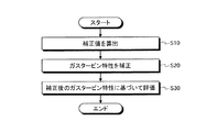
次に、上記のように構成されたガスタービン特性を評価する方法を説明する。図3は、ガスタービンの特性評価方法の一例を示すフローチャートである。図3に示すように、処理部63は、環境条件によるガスタービン特性への影響を補正するための補正値を算出する(ステップS10)。ステップS10において、特性モデル生成部64は、ガスタービン1の各特性についての特性モデルを生成し、生成した特性モデルに基づいて運転データの補正値を算出する。
Next, a method for evaluating the characteristics of the gas turbine configured as described above will be described. FIG. 3 is a flowchart showing an example of a method for evaluating the characteristics of a gas turbine. As shown in FIG. 3, the
次に、処理部63は、算出した補正値に基づいてガスタービン特性を補正する(ステップS20)。ステップS20において、補正部65は、ガスタービン特性毎に算出された補正値に基づいて、基準とする環境条件における補正後のガスタービン特性を求める。補正後のガスタービン特性は、環境条件による影響が除去又は低減された値となる。
Next, the
次に、処理部63は、補正後のガスタービン特性に基づいて評価する(ステップS30)。ステップS30において、評価部66は、補正後のガスタービン特性と、ガスタービン特性の実測値とを比較することにより、ガスタービン特性の評価を行う。環境条件による影響が除去又は低減されたガスタービン特性に基づく評価であるため、高精度の評価が得られる。
Next, the
以上のように、本実施形態に係るガスタービンの特性評価装置は、ガスタービン1の運転データに基づいて、環境条件による影響を補正するための補正値を算出するため、精度の高い補正値を得ることができる。この補正値に基づいてガスタービン特性を補正し、補正後のガスタービン特性と所定の基準値とを比較することによりガスタービン特性の評価を行うため、高精度の評価を行うことができる。 As described above, the gas turbine characteristic evaluation device according to the present embodiment calculates the correction value for correcting the influence of the environmental conditions based on the operation data of the gas turbine 1, so that the correction value with high accuracy can be obtained. Obtainable. Since the gas turbine characteristics are corrected based on this correction value and the corrected gas turbine characteristics are compared with a predetermined reference value to evaluate the gas turbine characteristics, highly accurate evaluation can be performed.
また、本実施形態に係るガスタービンの特性評価装置は、劣化によるガスタービン特性の変化の度合いを算出することができる。したがって、ガスタービン1毎の置かれた環境条件や、ガスタービン1毎の個別の運転データに応じた劣化特性を評価することができるため、高精度の評価を行うことができる。 Further, the gas turbine characteristic evaluation device according to the present embodiment can calculate the degree of change in gas turbine characteristics due to deterioration. Therefore, since it is possible to evaluate the deterioration characteristics according to the environmental conditions of each gas turbine 1 and the individual operation data of each gas turbine 1, high-precision evaluation can be performed.
本発明の技術範囲は上記実施形態に限定されるものではなく、本発明の趣旨を逸脱しない範囲で適宜変更を加えることができる。例えば、上記実施形態においては、特性モデル生成部64が線形重回帰分析を用いて特性モデルを生成する場合を例に挙げて説明したが、これに限定するものではなく、非線形の手法によって特性モデルを生成してもよい。
The technical scope of the present invention is not limited to the above-described embodiment, and modifications can be made as appropriate without departing from the spirit of the present invention. For example, in the above embodiment, the case where the characteristic
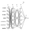
特性モデル生成部64は、非線形の手法として、例えばニューラルネットワークを用いて特性モデルを生成することができる。図9は、階層型ニューラルネットワークを用いて特性モデルを生成する様子を模式的に示す図である。図9では、特性モデル生成部として、出力モデルFX1を出力する出力モデル生成部64eを例に挙げて説明する。出力モデル生成部64eは、入力層である第1層L1と、中間層である第2層L2、第3層L3及び第4層L4と、出力層である第5層L5とを有している。なお、出力モデル生成部64eは、中間層が3層となっている構成であるが、これに限定されるものではなく、中間層が2層以下又は4層以上となっている構成でもよい。第1層L1、第2層L2、第3層L3、第4層L4及び第5層L5は、1つまたは複数のノードnを有している。
The characteristic
第1層L1は、7つのノードn(n1、n2、n3、n4、n5、n6、n7)を有している。ノードn1には、大気温度が入力される。ノードn2には、大気圧力が入力される。ノードn3には、相対湿度が入力される。ノードn4には、回転数が入力される。ノードn5には、入口圧力ロスが入力される。ノードn6には、出口圧力ロスが入力される。ノードn7には、運転時間が入力される。第1層L1の7つのノードnは、第2層L2の各ノードnに対して信号を出力する。 The first layer L1 has seven nodes n (n1, n2, n3, n4, n5, n6, n7). Atmospheric temperature is input to node n1. Atmospheric pressure is input to node n2. Relative humidity is input to node n3. The rotation speed is input to the node n4. The inlet pressure loss is input to the node n5. The outlet pressure loss is input to the node n6. The operation time is input to the node n7. The seven nodes n of the first layer L1 output signals to each node n of the second layer L2.
第2層L2は、例えば6つのノードnを有している。第2層L2の6つのノードnは、第1層L1の7つのノードnから出力された信号が入力される。第2層L2の6つのノードnは、第3層L3の各ノードnに対して信号を出力する。なお、第2層L2において、ノードnの数は6つに限定されるものではなく、5つ以下又は7つ以上であってもよい。 The second layer L2 has, for example, six nodes n. The signals output from the seven nodes n of the first layer L1 are input to the six nodes n of the second layer L2. The six nodes n of the second layer L2 output signals to each node n of the third layer L3. In the second layer L2, the number of nodes n is not limited to 6, and may be 5 or less or 7 or more.
第2層L3は、3つのノードnを有している。第3層L3の3つのノードnは、第2層L2の6つのノードnから出力された信号が入力される。第3層L3の6つのノードnは、第4層L4の各ノードnに対して信号を出力する。なお、第3層L3において、ノードnの数は3つに限定されるものではなく、2つ以下又は4つ以上であってもよい。 The second layer L3 has three nodes n. The signals output from the six nodes n of the second layer L2 are input to the three nodes n of the third layer L3. The six nodes n of the third layer L3 output signals to each node n of the fourth layer L4. In the third layer L3, the number of nodes n is not limited to three, and may be two or less or four or more.
第4層L4は、6つのノードnを有している。第4層L4の6つのノードnは、第3層L3の3つのノードnから出力された信号が入力される。第4層L4の6つのノードnは、第5層L5のノードnに対して信号を出力する。なお、第4層L4において、ノードnの数は6つに限定されるものではなく、5つ以下又は7つ以上であってもよい。 The fourth layer L4 has six nodes n. The signals output from the three nodes n of the third layer L3 are input to the six nodes n of the fourth layer L4. The six nodes n of the fourth layer L4 output signals to the nodes n of the fifth layer L5. In the fourth layer L4, the number of nodes n is not limited to six, and may be five or less or seven or more.
第5層L5は、1つのノードnを有している。第5層L5の3つのノードnは、第4層L4の6つのノードnから出力された信号が入力される。第5層L5のノードnは、例えば出力モデルFX1を出力する。なお、第5層L5において、ノードnの数は1つに限定されるものではなく、2つ以上であってもよい。 The fifth layer L5 has one node n. The signals output from the six nodes n of the fourth layer L4 are input to the three nodes n of the fifth layer L5. The node n of the fifth layer L5 outputs, for example, the output model FX1. In the fifth layer L5, the number of nodes n is not limited to one, and may be two or more.
なお、ここでは、出力モデル生成部64eがニューラルネットワークを用いて出力モデルFX1を出力する構成を例に挙げて説明したが、これに限定されるものではない。例えば、吸気流量モデルFX2を出力する吸気流量モデル生成部、圧縮機効率モデルFX3を出力する圧縮機効率モデル生成部、車室圧モデルFX4を出力する車室圧モデル生成部についても、上記のようなニューラルネットワークを用いて各特性モデルを出力する構成としてもよい。この場合、入力層のノード数、中間層の層数及び各層のノード数については、入力信号の種類に応じて適宜変更することができる。
Here, the configuration in which the output
また、図9では、階層型ニューラルネットワークが用いられる場合を例に挙げて説明したが、これに限定するものではなく、階層型ニューラルネットワークとは異なるニューラルネットワーク、例えば相互結合型ニューラルネットワーク等が用いられる構成であってもよい。 Further, in FIG. 9, the case where a hierarchical neural network is used has been described as an example, but the present invention is not limited to this, and a neural network different from the hierarchical neural network, for example, an interconnected neural network, is used. It may be configured to be.
図10は、大気温度についての補正値の一例を示すグラフである。図10の縦軸は補正係数(補正値)であり、横軸が大気温度である。図10に示すように、大気温度の曲線102は、曲線状であり、例えば大気温度が高くなるほど補正係数の減少量が小さくなっている。このように、図9に示すニューラルネットワーク等の非線形の手法を用いることにより、直線状には限られず、曲線状の曲線102についても得ることができため、より高精度な補正値を得ることができる。例えば、運転時間に対するガスタービン1の出力の変化など、予め特性を把握することが困難な場合であっても、より高精度な補正値を得ることができる。
FIG. 10 is a graph showing an example of a correction value for the atmospheric temperature. The vertical axis of FIG. 10 is the correction coefficient (correction value), and the horizontal axis is the atmospheric temperature. As shown in FIG. 10, the
また、上記実施形態の構成において、特性モデル生成部64は、ガスタービン特性の特性モデルを逐次的に更新するようにしてもよい。図11は、特性モデルを更新する手順を示すフローチャートである。図11に示すように、特性モデル生成部64は、特性モデルを更新するフラグの有無を検出する(ステップS40)。ステップS40において、特性モデルを更新するフラグとしては、例えば所定期間が経過した場合(例えば、1日経過した場合、1週間経過した場合、1か月経過した場合、等)や、所定の定期点検が行われた場合等に発生させることができる。フラグが検出されない場合(ステップS40のNo)、特性モデル生成部64はステップS40を繰り返し行う。
Further, in the configuration of the above embodiment, the characteristic
フラグが検出された場合(ステップS40のYes)、特性モデル生成部64は、ガスタービン特性の特性モデルを更新する(ステップS50)。ステップS50において、特性モデル生成部64は、入力される運転データに基づいて特性モデルを新たに生成する。生成された特性モデルは、前回特性モデルが生成されてからの運転データが蓄積された状態で新たに生成されるため、より高精度な特性モデルとなる。特性モデル生成部64は、生成した特性モデルに基づいて、運転データ毎に補正値を算出する。補正部65は、新たに算出された補正値に基づいてガスタービン特性を補正する。評価部66は、新たな補正値に基づいて補正されたガスタービン特性に基づいて評価を行う。このため、高精度の評価が得られる。
When the flag is detected (Yes in step S40), the characteristic
特性モデルを更新した後、特性モデル生成部64は、ガスタービン1の動作が終了しない場合には(ステップS60のNo)、ステップS40からの動作を繰り返し行う。また、ガスタービン1の動作が終了する場合(ステップS60のYes)、特性モデル生成部64は上記処理を終了する。
After updating the characteristic model, if the operation of the gas turbine 1 is not completed (No in step S60), the characteristic
このように、特性モデル生成部64は、特性モデルを更新することにより、蓄積された運転データに基づいて補正値を算出することができる。これにより、当該補正値に基づいて補正されたガスタービン特性を評価した場合、高精度の評価が得られる。
In this way, the characteristic
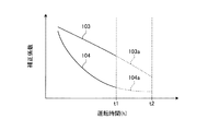
また、上記実施形態の構成において、特性モデル生成部64は、求めた補正値に基づいて将来の補正値を予測して算出してもよい。図12は、運転時間についての補正値の一例を示すグラフである。図12の縦軸は補正係数(補正値)であり、横軸が運転時間である。図12に示すように、例えば特性モデル生成部64が特性モデルを生成した時刻t1においては、運転時間の補正値として、時刻t1までの補正値が算出されている。直線103は、例えば線形重回帰分析によって得られた補正値である。曲線104は、例えば非線形の手法によって得られた補正値である。いずれの場合においても、時刻t1までの補正値が算出されている。
Further, in the configuration of the above embodiment, the characteristic
この状態において、特性モデル生成部64は、直線103及び曲線104の傾向に基づいて、将来の補正値、例えば時刻t1よりも後の時刻t2までの補正値を予測してもよい。直線103a及び曲線104aは、直線103及び曲線104に基づいて予測された補正値を示す。この場合、補正部65は、予測された補正値に基づいてガスタービン特性を補正することで、将来の補正後のガスタービン特性を算出してもよい。また、評価部66は、算出された将来の補正後のガスタービン特性に基づいて評価を行ってもよい。これにより、将来のガスタービン特性に関する評価を得ることができる。
In this state, the characteristic
また、上記実施形態では、例えば出力モデル生成部64aは、運転データとして、大気温度、大気圧力、相対湿度、回転数、入口圧力ロス、出口圧力ロス、及び運転時間が入力される構成を例に挙げて説明したが、これに限定するものではなく、他の運転データが入力される構成であってもよい。
Further, in the above embodiment, for example, the output
図13は、出力モデル生成部64aの一例を示すブロック図である。図13に示すように、出力モデル生成部64aは、上記の運転データに加えて、定期点検からの経過時間のデータが入力される構成であってもよい。出力モデル生成部64aは、これらの各運転データに基づいて、ガスタービン1の出力特性のモデルである出力モデルFX1aを生成し、生成した出力モデルFX1aに基づいて各運伝データの補正値を算出する。
FIG. 13 is a block diagram showing an example of the output
図14は、ガスタービン1の運転時間と定期点検からの経過時間との関係を示すグラフである。図14に示すように、ガスタービン1の定期点検は、例えば運転開始からの時刻t3、t4、t5及びt6において、定期的に行われる。折れ線105は、定期点検ごとに経過時間がリセットされる状態を示している。定期点検には、例えば燃焼器12の点検である燃焼器点検と、タービン13の点検であるタービン点検と、メジャー点検とがある。タービン点検を行うことにより、燃焼器点検も併せて行われる。メジャー点検を行うことにより、タービン点検及び燃焼器点検も併せて行われる。
FIG. 14 is a graph showing the relationship between the operating time of the gas turbine 1 and the elapsed time from the periodic inspection. As shown in FIG. 14, the periodic inspection of the gas turbine 1 is performed periodically, for example, at times t3, t4, t5 and t6 from the start of operation. The
図15は、定期点検が行われる場合における運転時間と補正係数との関係を示すグラフである。ガスタービン1においては、定期点検が行われる度に、例えば出力の低下が改善される、つまり、定期点検が行われる度に出力が上昇する。したがって、汚れや劣化等の評価を行う場合、定期点検による出力増加の影響を除外又は低減する必要がある。そこで、図15に示すように、出力モデル生成部64aは、運転開始から定期点検が行われる時刻t3、t4、t5、t6のそれぞれにおいて、出力上昇の影響が除外又は低減されるように補正値を算出する。このため、補正値を示す折れ線106の形状は、例えば時刻t3、t4、t5、t6において急激に上昇した状態となる。このように、定期点検が出力等のガスタービン特性に与える影響を反映させることにより、より高精度の補正値、ひいては評価が得られることになる。
FIG. 15 is a graph showing the relationship between the operation time and the correction coefficient when the periodic inspection is performed. In the gas turbine 1, for example, the decrease in output is improved every time the periodic inspection is performed, that is, the output increases every time the periodic inspection is performed. Therefore, when evaluating dirt, deterioration, etc., it is necessary to exclude or reduce the effect of increased output due to periodic inspections. Therefore, as shown in FIG. 15, the output
1 ガスタービン
11 圧縮機
12 燃焼器
13 タービン
14 制御装置
15 発電機
18 ロータ
19 冷却用空気供給ライン
20 冷却用空気制御弁
22 入口案内翼
22a 翼本体
22b IGV作動部
35 燃料調整弁
51 車室圧力計
52 吸気状態検出器
53 ブレードパス温度計
54 排ガス温度計
55 流量計
56 出力計
61 制御部
62 記憶部
63 処理部
64 特性モデル生成部
64a,64e 出力モデル生成部
64b 吸気流量モデル生成部
64c 圧縮機効率モデル生成部
64d 車室圧モデル生成部
65 補正部
66 評価部
101,103,103a 直線
102,104,104a 曲線
105,106 折れ線
A 空気
A1 圧縮空気
F 燃料
H0,P0,R0,T0,Pe0,Pi0 基準値
FX1,FX1a 出力モデル
FX2 吸気流量モデル
FX3 圧縮機効率モデル
FX4 車室圧モデル
L1 第1層
L2 第2層
L3 第3層
L4 第4層
L5 第5層
n,n1,n2,n3,n4,n5,n6,n7 ノード
t1,t2,t3,t4,t5,t6 時刻
1 Gas turbine 11
Claims (5)
燃料が供給され前記圧縮機で圧縮された圧縮空気を燃焼させる燃焼器と、
前記燃焼器で生じた燃焼ガスにより回転するタービンと、
を備えるガスタービンの特性評価装置であって、
前記圧縮機、前記燃焼器及び前記タービンのうち少なくとも1つについての特性を含むガスタービン特性の前記ガスタービンが配置される環境条件による影響を補正するための補正値を前記ガスタービンの運転データに基づいて算出し、前記補正値に基づいて補正された前記ガスタービン特性を算出し、補正後の前記ガスタービン特性と所定の基準値とを比較することにより前記ガスタービンの評価を行う処理部を備え、
前記運転データは、前記ガスタービンの定期点検からの経過時間を含み、
前記処理部は、前記運転データに基づいて前記ガスタービン特性のモデル値を算出し、前記モデル値に基づいて前記補正値を推定すると共に、前記定期点検が行われた場合に前記モデル値を更新し、
前記処理部は、補正後の前記ガスタービン特性と前記所定の基準値とに基づいて、前記ガスタービン特性の変化の要因を評価する
ガスタービンの特性評価装置。 A compressor that compresses air,
A combustor to which fuel is supplied and the compressed air compressed by the compressor is burned,
A turbine that is rotated by the combustion gas generated by the combustor,
It is a characteristic evaluation device of a gas turbine equipped with
The compressor, the combustor and operating data of the gas turbine a correction value for correcting the influence of environmental conditions prior SL gas turbine is disposed in the gas turbine characteristics, including characteristics of at least one of the turbine The processing unit that evaluates the gas turbine by calculating based on the above, calculating the corrected gas turbine characteristics based on the corrected value, and comparing the corrected gas turbine characteristics with a predetermined reference value. With
The operation data includes the elapsed time from the periodic inspection of the gas turbine.
The processing unit calculates a model value of the gas turbine characteristic based on the operation data, estimates the correction value based on the model value, and updates the model value when the periodic inspection is performed. And
The processing unit is a gas turbine characteristic evaluation device that evaluates factors of changes in the gas turbine characteristics based on the corrected gas turbine characteristics and the predetermined reference value.
燃料が供給され前記圧縮機で圧縮された圧縮空気を燃焼させる燃焼器と、
前記燃焼器で生じた燃焼ガスにより回転するタービンと、
を備えるガスタービンの特性評価方法であって、
前記圧縮機、前記燃焼器及び前記タービンのうち少なくとも1つについての特性を含むガスタービン特性の前記ガスタービンが配置される環境条件による影響を補正するための補正値を前記ガスタービンの運転データに基づいて算出することと、
前記補正値に基づいて補正された前記ガスタービン特性を算出することと、
補正後の前記ガスタービン特性と所定の基準値とを比較することにより前記ガスタービンの評価を行うことと、
を含み、
前記運転データは、前記ガスタービンの定期点検からの経過時間を含み、
前記運転データに基づいて前記ガスタービン特性のモデル値を算出し、前記モデル値に基づいて前記補正値を推定することと、
前記定期点検が行われた場合に前記モデル値を更新することと、をさらに含み、
前記ガスタービンの評価は、補正後の前記ガスタービン特性と前記所定の基準値とに基づいて、前記ガスタービン特性の変化の要因を評価することを含む
ガスタービンの特性評価方法。 A compressor that compresses air,
A combustor to which fuel is supplied and the compressed air compressed by the compressor is burned,
A turbine that is rotated by the combustion gas generated by the combustor,
It is a characteristic evaluation method of a gas turbine equipped with
The compressor, the combustor and operating data of the gas turbine a correction value for correcting the influence of environmental conditions prior SL gas turbine is disposed in the gas turbine characteristics, including characteristics of at least one of the turbine To calculate based on
To calculate the corrected gas turbine characteristics based on the correction value,
To evaluate the gas turbine by comparing the corrected gas turbine characteristics with a predetermined reference value, and
Including
The operation data includes the elapsed time from the periodic inspection of the gas turbine.
The model value of the gas turbine characteristic is calculated based on the operation data, and the correction value is estimated based on the model value.
Further including updating the model value when the periodic inspection is performed,
The evaluation of the gas turbine is a method for evaluating the characteristics of a gas turbine, which comprises evaluating the factors of change in the characteristics of the gas turbine based on the corrected characteristics of the gas turbine and the predetermined reference value.
Priority Applications (8)
| Application Number | Priority Date | Filing Date | Title |
|---|---|---|---|
| JP2016057187A JP6786233B2 (en) | 2016-03-22 | 2016-03-22 | Gas turbine characterization device and gas turbine characterization method |
| KR1020187026829A KR20180110678A (en) | 2016-03-22 | 2016-11-28 | Apparatus for evaluating characteristics of gas turbine and evaluation method of characteristics of gas turbine |
| PCT/JP2016/085176 WO2017163489A1 (en) | 2016-03-22 | 2016-11-28 | Gas turbine characteristic evaluation device and gas turbine characteristic evaluation method |
| DE112016006642.2T DE112016006642B4 (en) | 2016-03-22 | 2016-11-28 | GAS TURBINE PROPERTIES EVALUATION DEVICE AND GAS TURBINE PROPERTIES EVALUATION METHOD |
| US16/083,282 US10636224B2 (en) | 2016-03-22 | 2016-11-28 | Characteristic evaluation device for gas turbine and characteristic evaluation method for gas turbine |
| MX2018011093A MX2018011093A (en) | 2016-03-22 | 2016-11-28 | Gas turbine characteristic evaluation device and gas turbine characteristic evaluation method. |
| CN201680083800.1A CN108779713B (en) | 2016-03-22 | 2016-11-28 | Gas turbine characteristic evaluation device and gas turbine characteristic evaluation method |
| PH12018502009A PH12018502009A1 (en) | 2016-03-22 | 2018-09-19 | Characteristic evaluation device for gas turbine and characteristic evaluation method for gas turbine |
Applications Claiming Priority (1)
| Application Number | Priority Date | Filing Date | Title |
|---|---|---|---|
| JP2016057187A JP6786233B2 (en) | 2016-03-22 | 2016-03-22 | Gas turbine characterization device and gas turbine characterization method |
Publications (3)
| Publication Number | Publication Date |
|---|---|
| JP2017172391A JP2017172391A (en) | 2017-09-28 |
| JP2017172391A5 JP2017172391A5 (en) | 2019-05-09 |
| JP6786233B2 true JP6786233B2 (en) | 2020-11-18 |
Family
ID=59901089
Family Applications (1)
| Application Number | Title | Priority Date | Filing Date |
|---|---|---|---|
| JP2016057187A Active JP6786233B2 (en) | 2016-03-22 | 2016-03-22 | Gas turbine characterization device and gas turbine characterization method |
Country Status (8)
| Country | Link |
|---|---|
| US (1) | US10636224B2 (en) |
| JP (1) | JP6786233B2 (en) |
| KR (1) | KR20180110678A (en) |
| CN (1) | CN108779713B (en) |
| DE (1) | DE112016006642B4 (en) |
| MX (1) | MX2018011093A (en) |
| PH (1) | PH12018502009A1 (en) |
| WO (1) | WO2017163489A1 (en) |
Families Citing this family (4)
| Publication number | Priority date | Publication date | Assignee | Title |
|---|---|---|---|---|
| EP3969967A1 (en) | 2019-05-13 | 2022-03-23 | Safran Aircraft Engines | Model resetting in a turbine engine |
| FR3096137B1 (en) * | 2019-05-13 | 2021-04-23 | Safran Aircraft Engines | PS3 model registration in a turbomachine |
| KR102452608B1 (en) * | 2021-03-04 | 2022-10-07 | 인하대학교 산학협력단 | Method for Gas turbine control based on artificial intelligence and apparatus thereof |
| JP7458357B2 (en) | 2021-09-24 | 2024-03-29 | 三菱パワー株式会社 | Model learning device, performance evaluation device, model learning method, and program |
Family Cites Families (47)
| Publication number | Priority date | Publication date | Assignee | Title |
|---|---|---|---|---|
| JPH05195720A (en) * | 1992-01-21 | 1993-08-03 | Toshiba Corp | Managing method for degradation in performance of plant |
| JP3538670B2 (en) * | 2000-09-04 | 2004-06-14 | 川崎重工業株式会社 | Gas turbine operating state diagnosis method and diagnosis apparatus |
| JP3922426B2 (en) * | 2001-09-14 | 2007-05-30 | 石川島播磨重工業株式会社 | Gas turbine performance diagnosis method |
| US6823675B2 (en) * | 2002-11-13 | 2004-11-30 | General Electric Company | Adaptive model-based control systems and methods for controlling a gas turbine |
| US7577549B2 (en) | 2005-07-18 | 2009-08-18 | General Electric Company | System and method for trending exhaust gas temperature in a turbine engine |
| JP4801452B2 (en) | 2006-01-19 | 2011-10-26 | 三菱重工業株式会社 | Abnormality monitoring method and apparatus for gas turbine |
| US20110106680A1 (en) * | 2009-10-30 | 2011-05-05 | General Electric Company | Turbine operation degradation determination system and method |
| US8171717B2 (en) * | 2010-05-14 | 2012-05-08 | General Electric Company | Model-based coordinated air-fuel control for a gas turbine |
| US8423161B2 (en) * | 2011-08-24 | 2013-04-16 | General Electric Company | Methods and systems for gas turbine modeling using adaptive kalman filter |
| US20130066615A1 (en) * | 2011-09-14 | 2013-03-14 | General Electric Company | System and method for simulating gas turbine operation |
| US8452515B2 (en) * | 2011-09-15 | 2013-05-28 | General Electric Company | System and method for simulating a gas turbine compressor |
| US9322333B2 (en) * | 2012-01-06 | 2016-04-26 | General Electric Company | System and method for determining a cooling flow parameter downstream from a gas turbine combustor |
| GB2519014A (en) * | 2012-08-03 | 2015-04-08 | Hitachi Ltd | Twin-shaft gas turbine power generation system, and control device and control method for gas turbine system |
| US9540944B2 (en) * | 2012-09-28 | 2017-01-10 | United Technologies Corporation | Real time model based compressor control |
| CN102953835B (en) * | 2012-11-09 | 2014-11-19 | 沈阳黎明航空发动机(集团)有限责任公司 | Control device and control method for stable running of gas turbine |
| JP6116871B2 (en) * | 2012-11-22 | 2017-04-19 | 三菱日立パワーシステムズ株式会社 | Power generation system and method for operating power generation system |
| US9255525B2 (en) | 2012-11-30 | 2016-02-09 | General Electric Company | System and method for gas turbine operation |
| EP2738373A1 (en) * | 2012-12-03 | 2014-06-04 | Siemens Aktiengesellschaft | Gas turbine fuel supply method and arrangement |
| EP2738374A1 (en) * | 2012-12-03 | 2014-06-04 | Siemens Aktiengesellschaft | Method and arrangement for controlling fuel supply for a gas turbine |
| US10208677B2 (en) * | 2012-12-31 | 2019-02-19 | General Electric Company | Gas turbine load control system |
| US9291093B2 (en) * | 2013-02-08 | 2016-03-22 | GM Global Technology Operations LLC | Turbocharger flow control |
| US9856795B2 (en) * | 2013-02-26 | 2018-01-02 | Mitsubishi Hitachi Power Systems, Ltd. | Gas turbine system, controller, and gas turbine operation method |
| US9014945B2 (en) * | 2013-03-08 | 2015-04-21 | General Electric Company | Online enhancement for improved gas turbine performance |
| US10107204B2 (en) * | 2013-03-15 | 2018-10-23 | United Technologies Corporation | Compact aero-thermo model base point linear system based state estimator |
| GB201313140D0 (en) * | 2013-07-23 | 2013-09-04 | Rolls Royce Engine Control Systems Ltd | System for performing staging control of a multi-stage combustor |
| US9696697B2 (en) * | 2013-09-04 | 2017-07-04 | General Electric Company | Automatic switching of HMI screens based on process, task, and abnormal deviation in a power plant |
| ITBO20130480A1 (en) * | 2013-09-10 | 2015-03-11 | Magneti Marelli Spa | METHOD OF CORRECTION OF THE REDUCED MASS CAPACITY OF A COMPRESSOR IN AN INTERNAL TURBOCHROME COMBUSTION ENGINE BY A TURBOCHARGER |
| WO2015042123A1 (en) * | 2013-09-17 | 2015-03-26 | General Electric Company | System and method for controlling operation of a gas turbine based power plant |
| EP2868898A1 (en) * | 2013-10-30 | 2015-05-06 | Siemens Aktiengesellschaft | Improved partial load operation of a gas turbine with an adjustable bypass flow channel |
| US20160252015A1 (en) * | 2013-11-27 | 2016-09-01 | Hitachi, Ltd. | Gas Turbine Corresponding to Renewable Energy and Control Method Therefor |
| US9453767B2 (en) * | 2013-12-18 | 2016-09-27 | Siemens Energy, Inc. | Active temperature monitoring in gas turbine combustors |
| US20150184549A1 (en) * | 2013-12-31 | 2015-07-02 | General Electric Company | Methods and systems for enhancing control of power plant generating units |
| US9404426B2 (en) * | 2013-12-31 | 2016-08-02 | General Electric Company | Methods and systems for enhancing control of power plant generating units |
| US9863267B2 (en) * | 2014-01-21 | 2018-01-09 | General Electric Company | System and method of control for a gas turbine engine |
| JP6257035B2 (en) * | 2014-03-25 | 2018-01-10 | 三菱日立パワーシステムズ株式会社 | Combustion control device, combustion control method and program for gas turbine |
| WO2015193979A1 (en) * | 2014-06-18 | 2015-12-23 | 株式会社日立製作所 | Multi-shaft variable-speed gas turbine device and control method therefor |
| US9885290B2 (en) * | 2014-06-30 | 2018-02-06 | General Electric Company | Erosion suppression system and method in an exhaust gas recirculation gas turbine system |
| EP2966525A1 (en) * | 2014-07-11 | 2016-01-13 | Alstom Technology Ltd | Method for the control and protection of a gas turbine and gas turbine using such method |
| US9528913B2 (en) * | 2014-07-24 | 2016-12-27 | General Electric Company | Method and systems for detection of compressor surge |
| US20160147204A1 (en) * | 2014-11-26 | 2016-05-26 | General Electric Company | Methods and systems for enhancing control of power plant generating units |
| US9932850B2 (en) * | 2015-02-03 | 2018-04-03 | General Electric Company | Correction system and method for gas turbine proportional droop governor |
| US10287988B2 (en) * | 2015-03-27 | 2019-05-14 | General Electric Company | Methods and systems for enhancing operation of power plant generating units and systems |
| JP6248993B2 (en) * | 2015-07-31 | 2017-12-20 | トヨタ自動車株式会社 | Control device for internal combustion engine |
| GB2532593A (en) * | 2015-10-12 | 2016-05-25 | Gm Global Tech Operations Llc | A method of controlling the operation of an air charging system of an internal combustion engine |
| US10466661B2 (en) * | 2015-12-18 | 2019-11-05 | General Electric Company | Model-based performance estimation |
| JP6706936B2 (en) * | 2016-03-09 | 2020-06-10 | 三菱日立パワーシステムズ株式会社 | Gas turbine control device and gas turbine control method |
| KR101971337B1 (en) * | 2017-04-24 | 2019-04-22 | 두산중공업 주식회사 | Gas Turbine System and Controlling Method thereof |
-
2016
- 2016-03-22 JP JP2016057187A patent/JP6786233B2/en active Active
- 2016-11-28 DE DE112016006642.2T patent/DE112016006642B4/en active Active
- 2016-11-28 MX MX2018011093A patent/MX2018011093A/en unknown
- 2016-11-28 US US16/083,282 patent/US10636224B2/en active Active
- 2016-11-28 KR KR1020187026829A patent/KR20180110678A/en not_active Application Discontinuation
- 2016-11-28 CN CN201680083800.1A patent/CN108779713B/en active Active
- 2016-11-28 WO PCT/JP2016/085176 patent/WO2017163489A1/en active Application Filing
-
2018
- 2018-09-19 PH PH12018502009A patent/PH12018502009A1/en unknown
Also Published As
| Publication number | Publication date |
|---|---|
| JP2017172391A (en) | 2017-09-28 |
| MX2018011093A (en) | 2018-11-22 |
| US20190080523A1 (en) | 2019-03-14 |
| CN108779713A (en) | 2018-11-09 |
| KR20180110678A (en) | 2018-10-10 |
| DE112016006642B4 (en) | 2023-07-06 |
| DE112016006642T5 (en) | 2018-12-20 |
| CN108779713B (en) | 2020-11-13 |
| WO2017163489A1 (en) | 2017-09-28 |
| PH12018502009A1 (en) | 2019-07-01 |
| US10636224B2 (en) | 2020-04-28 |
Similar Documents
| Publication | Publication Date | Title |
|---|---|---|
| JP6786233B2 (en) | Gas turbine characterization device and gas turbine characterization method | |
| US8452515B2 (en) | System and method for simulating a gas turbine compressor | |
| US8014929B2 (en) | Method of monitoring a gas turbine engine | |
| CN106404403B (en) | Method and system for analysis of a turbomachine | |
| EP2570877A1 (en) | System and method for simulating gas turbine operation | |
| CN102953833B (en) | The method and system of gas turbine modeling is carried out with adaptive Kalman filter | |
| RU2406990C1 (en) | Procedure for operating gas turbine installation | |
| JP2009162230A (en) | Method and system for materializing real-time comparison with using alternative control system on turbine | |
| JP2003129866A (en) | Adaptive aero-thermodynamic engine model | |
| JP6636021B2 (en) | How to identify emission behavior | |
| JP2018204604A (en) | Systems and methods for icing detection of compressors | |
| KR20190002612A (en) | Diagnosis of defects during test of turbine unit | |
| US20210277833A1 (en) | Systems, program products, and methods for adjusting operating limit (ol) threshold for compressors of gas turbine systems based on mass flow loss | |
| JP6906935B2 (en) | Equipment-specific stochastic controls, related control systems, computer program products, and methods for gas turbine regulation with respect to output-emission parameters. | |
| CN106050435B (en) | Regulation and control system, computer program product and method for a gas turbine | |
| US9599032B2 (en) | Application of probabilistic control in gas turbine tuning for emissions-fuel flow parameters, related control systems, computer program products and methods | |
| CN105604703B (en) | For tuning computing device, the system and method for combustion gas turbine | |
| JP6640534B2 (en) | Control system, computer program product, and method associated with application of fuel flow based stochastic control in gas turbine tuning under partial load | |
| US10400624B2 (en) | System and method for planning engine borescope inspections based on FOD probability estimation | |
| US9599033B2 (en) | Application of probabilistic control in gas turbine tuning for fuel flow-exhaust energy parameters, related control systems, computer program products and methods | |
| US20190376407A1 (en) | Method for determining a measurand and sensor system | |
| US9599030B2 (en) | Application of probabilistic control in gas turbine tuning for exhaust energy-fuel flow parameters, related control systems, computer program products and methods | |
| US9599027B2 (en) | Application of probabilistic control in gas turbine tuning for emissions-exhaust energy parameters, related control systems, computer program products and methods | |
| EP3081786A1 (en) | Application of probabilistic control in gas turbine tuning for exhaust energy-emissions parameters, related control systems, computer porgram products and methods |
Legal Events
| Date | Code | Title | Description |
|---|---|---|---|
| A521 | Request for written amendment filed |
Free format text: JAPANESE INTERMEDIATE CODE: A523 Effective date: 20190320 |
|
| A621 | Written request for application examination |
Free format text: JAPANESE INTERMEDIATE CODE: A621 Effective date: 20190320 |
|
| A131 | Notification of reasons for refusal |
Free format text: JAPANESE INTERMEDIATE CODE: A131 Effective date: 20200128 |
|
| A521 | Request for written amendment filed |
Free format text: JAPANESE INTERMEDIATE CODE: A523 Effective date: 20200312 |
|
| A131 | Notification of reasons for refusal |
Free format text: JAPANESE INTERMEDIATE CODE: A131 Effective date: 20200526 |
|
| A521 | Request for written amendment filed |
Free format text: JAPANESE INTERMEDIATE CODE: A523 Effective date: 20200710 |
|
| TRDD | Decision of grant or rejection written | ||
| A01 | Written decision to grant a patent or to grant a registration (utility model) |
Free format text: JAPANESE INTERMEDIATE CODE: A01 Effective date: 20200929 |
|
| A61 | First payment of annual fees (during grant procedure) |
Free format text: JAPANESE INTERMEDIATE CODE: A61 Effective date: 20201028 |
|
| R150 | Certificate of patent or registration of utility model |
Ref document number: 6786233 Country of ref document: JP Free format text: JAPANESE INTERMEDIATE CODE: R150 |