WO2017163302A1 - 制御装置 - Google Patents
制御装置 Download PDFInfo
- Publication number
- WO2017163302A1 WO2017163302A1 PCT/JP2016/058928 JP2016058928W WO2017163302A1 WO 2017163302 A1 WO2017163302 A1 WO 2017163302A1 JP 2016058928 W JP2016058928 W JP 2016058928W WO 2017163302 A1 WO2017163302 A1 WO 2017163302A1
- Authority
- WO
- WIPO (PCT)
- Prior art keywords
- cpu
- shared memory
- error
- access
- circuit
- Prior art date
Links
Images


Classifications
-
- G—PHYSICS
- G06—COMPUTING; CALCULATING OR COUNTING
- G06F—ELECTRIC DIGITAL DATA PROCESSING
- G06F15/00—Digital computers in general; Data processing equipment in general
- G06F15/16—Combinations of two or more digital computers each having at least an arithmetic unit, a program unit and a register, e.g. for a simultaneous processing of several programs
- G06F15/163—Interprocessor communication
- G06F15/167—Interprocessor communication using a common memory, e.g. mailbox
-
- G—PHYSICS
- G06—COMPUTING; CALCULATING OR COUNTING
- G06F—ELECTRIC DIGITAL DATA PROCESSING
- G06F11/00—Error detection; Error correction; Monitoring
- G06F11/07—Responding to the occurrence of a fault, e.g. fault tolerance
- G06F11/0703—Error or fault processing not based on redundancy, i.e. by taking additional measures to deal with the error or fault not making use of redundancy in operation, in hardware, or in data representation
- G06F11/0706—Error or fault processing not based on redundancy, i.e. by taking additional measures to deal with the error or fault not making use of redundancy in operation, in hardware, or in data representation the processing taking place on a specific hardware platform or in a specific software environment
- G06F11/0721—Error or fault processing not based on redundancy, i.e. by taking additional measures to deal with the error or fault not making use of redundancy in operation, in hardware, or in data representation the processing taking place on a specific hardware platform or in a specific software environment within a central processing unit [CPU]
-
- G—PHYSICS
- G06—COMPUTING; CALCULATING OR COUNTING
- G06F—ELECTRIC DIGITAL DATA PROCESSING
- G06F11/00—Error detection; Error correction; Monitoring
- G06F11/07—Responding to the occurrence of a fault, e.g. fault tolerance
- G06F11/0703—Error or fault processing not based on redundancy, i.e. by taking additional measures to deal with the error or fault not making use of redundancy in operation, in hardware, or in data representation
- G06F11/0766—Error or fault reporting or storing
- G06F11/0772—Means for error signaling, e.g. using interrupts, exception flags, dedicated error registers
-
- G—PHYSICS
- G06—COMPUTING; CALCULATING OR COUNTING
- G06F—ELECTRIC DIGITAL DATA PROCESSING
- G06F9/00—Arrangements for program control, e.g. control units
- G06F9/06—Arrangements for program control, e.g. control units using stored programs, i.e. using an internal store of processing equipment to receive or retain programs
- G06F9/46—Multiprogramming arrangements
- G06F9/52—Program synchronisation; Mutual exclusion, e.g. by means of semaphores
-
- G—PHYSICS
- G06—COMPUTING; CALCULATING OR COUNTING
- G06F—ELECTRIC DIGITAL DATA PROCESSING
- G06F9/00—Arrangements for program control, e.g. control units
- G06F9/06—Arrangements for program control, e.g. control units using stored programs, i.e. using an internal store of processing equipment to receive or retain programs
- G06F9/46—Multiprogramming arrangements
- G06F9/54—Interprogram communication
- G06F9/544—Buffers; Shared memory; Pipes
-
- G—PHYSICS
- G06—COMPUTING; CALCULATING OR COUNTING
- G06F—ELECTRIC DIGITAL DATA PROCESSING
- G06F11/00—Error detection; Error correction; Monitoring
- G06F11/07—Responding to the occurrence of a fault, e.g. fault tolerance
- G06F11/0703—Error or fault processing not based on redundancy, i.e. by taking additional measures to deal with the error or fault not making use of redundancy in operation, in hardware, or in data representation
- G06F11/0751—Error or fault detection not based on redundancy
Definitions
- Embodiments of the present invention relate to a control device.
- a control apparatus including a processor that executes a predetermined task is known.
- a plurality of processors may be provided.
- each processor may be configured to transmit and receive data via one shared memory.
- each processor in order to acquire data from other processors, each processor periodically and repeatedly accesses the shared memory in addition to the preset task, and the data from the other processors is written into the shared memory. It is necessary to perform processing to check whether or not. For this reason, conventionally, the processing load when transmitting and receiving data via the shared memory may increase.
- the control device includes a first device including a first control unit, a second device including a second control unit, a shared memory, and a first circuit.
- the shared memory is configured to be shared by the first device and the second device.
- the first circuit is configured to acquire information related to access from the second device when the second control unit accesses the shared memory, and output the acquired information related to access to the first device. .
- FIG. 1 is an exemplary block diagram illustrating a configuration of a control device according to the first embodiment.
- FIG. 2 is an exemplary flowchart showing processing executed by the diagnostic circuit according to the first embodiment.
- FIG. 3 is an exemplary flowchart showing processing executed by the monitoring circuit according to the first embodiment.
- FIG. 4 is an exemplary flowchart showing processing executed by the CPU of the master device according to the first embodiment.
- FIG. 5 is an exemplary block diagram illustrating a configuration of a control device according to the second embodiment.
- FIG. 6 is an exemplary flowchart showing processing executed by the diagnostic circuit according to the second embodiment.
- FIG. 7 is an exemplary flowchart showing processing executed by the monitoring circuit according to the second embodiment.
- FIG. 8 is an exemplary flowchart showing processing executed by the CPU of the master device according to the second embodiment.
- the control device 100 is a controller used in the instrumentation field, the electric control field, the power field, and the like.
- the control device 100 includes a mother board 10, a master device 20, and a plurality of slave devices 30.
- the master device 20 and the slave device 30 are connected to the motherboard 10.
- the master device 20 is an example of a “first device”
- the slave device 30 is an example of a “second device”.
- FIG. 1 shows an example in which three slave devices 30 are provided, the number of slave devices 30 may be four or more, or may be two or less.
- the motherboard 10 includes a shared memory 11 and an arbitration circuit 12.
- the shared memory 11 is configured to be shared by the master device 20 and the slave device 30. That is, the master device 20 and the slave device 30 are configured to transmit and receive data via the shared memory 11.
- the arbitration circuit 12 is configured to arbitrate competition for access to the shared memory 11. That is, the arbitration circuit 12 is configured to avoid contention between the access to the shared memory 11 by the master device 20 and the access to the shared memory 11 by the slave device 30.
- the master device 20 includes a CPU (Central Processing Unit) 21 configured to be able to perform various processes based on data acquired from the slave device 30 via the shared memory 11.
- the master device 20 is connected to the host device 40 and is configured to be able to output the result of processing by the CPU 21 to the host device 40.
- the CPU 21 is an example of a “first control unit”.
- the slave device 30 is connected to an input / output device (I / O device) 50.
- the slave device 30 includes a CPU 31 configured to perform various processes based on data input via the I / O device 50 and to output the processing results to the shared memory 11.
- the CPU 31 is an example of a “second control unit”.
- the slave device 30 also includes a peripheral device 32 such as a memory.
- the motherboard 10 acquires information related to the access from the slave device 30, and transmits the acquired information related to access to the master device 20. And a monitoring circuit 13 configured to do so.
- the monitoring circuit 13 is configured by hardware such as an FPGA (Field Programmable Gate Array).
- the monitoring circuit 13 is an example of a “first circuit”.
- the information related to access includes information indicating the address of the shared memory 11 accessed by the CPU 31, information indicating whether the access performed by the CPU 31 is data writing or data reading, and the like. For example, information relating to such access is obtained by monitoring a bus (see a straight line L with an arrow in FIG. 1) between the CPU 31 and the shared memory 11 and intercepting a signal output from the CPU 31 to the shared memory 11. It can be obtained by.
- the slave device 30 acquires the information related to the access by monitoring the bus (see the straight line L with an arrow in FIG. 1) between the CPU 31 and the shared memory 11, and the acquired access.
- a diagnostic circuit 33 configured to transmit information about the to the monitoring circuit 13.
- the diagnostic circuit 33 is configured by hardware such as an FPGA (Field Programmable Gate Array).
- the diagnostic circuit 33 is an example of a “second circuit”.
- the master device 20 includes a register 22 configured to store information related to access acquired from the monitoring circuit 13.
- the CPU 21 of the master device 20 is configured to access the shared memory 11 based on the register 22.
- the diagnostic circuit 33 monitors information indicating the address of the shared memory 11 to which the CPU 31 has written data as information related to access. It is configured to output to the circuit 13. Then, the monitoring circuit 13 writes in the register 22 of the master device 20 information that can specify which CPU 31 has written the data in which address of the shared memory 11 based on the information acquired from the diagnostic circuit 33. It is configured.
- the register 22 is configured to output an interrupt signal to the CPU 21 when the above information is written by the diagnostic circuit 33. Then, when an interrupt signal is input from the register 22, the CPU 21 temporarily stops processing currently being performed, reads information from the register 22, and accesses the shared memory 11 based on the read information, whereby the CPU 31 Is configured to acquire data written to the shared memory 11 from the shared memory 11.
- the diagnostic circuit 33 first determines whether or not the CPU 31 of the slave device 30 has accessed the shared memory 11 in step S1. More specifically, the diagnostic circuit 33 monitors the bus between the CPU 31 and the shared memory 11 (see a straight line L with an arrow in FIG. 1), and a signal indicating that the CPU 31 has accessed the shared memory 11 is a bus. It is determined whether it is output above. The process in step S1 is repeated until it is determined by the CPU 31 that the shared memory 11 has been accessed. If it is determined in step S1 that the CPU 31 has accessed the shared memory 11, the process proceeds to step S2.
- step S2 the diagnostic circuit 33 outputs information related to the access to the shared memory 11 performed by the CPU 31 to the monitoring circuit 13 of the motherboard 10.
- the information related to access includes information indicating the address of the shared memory 11 accessed by the CPU 31, information indicating whether the access performed by the CPU 31 is data writing or data reading, and the like.
- Information regarding access is generated based on a signal intercepted from a bus between the CPU 31 and the shared memory 11 (see a straight line L with an arrow in FIG. 1). Then, the process returns.
- the monitoring circuit 13 first determines in step S11 whether or not information related to access to the shared memory 11 performed by the CPU 31 of the slave device 30 has been input from the diagnostic circuit 33. to decide. The process of step S11 is repeated until it is determined that information related to access is input from the diagnostic circuit 33. If it is determined in step S11 that information related to access has been input from the diagnostic circuit 33, the process proceeds to step S12.
- step S ⁇ b> 12 the monitoring circuit 13 outputs information related to access input from the diagnostic circuit 33 to the register 22 of the master device 20. For example, when the CPU 31 of the slave device 30 writes data to the shared memory 11, the monitoring circuit 13 writes information or the like that can specify to which address of the shared memory 11 the CPU 31 has written data to the register 22. Then, the process returns.
- the CPU 21 first determines whether or not the information related to the access to the shared memory 11 performed by the CPU 31 is stored in the register 22 in step S21. For example, assuming that the register 22 is configured to output an interrupt signal to the CPU 21 when information related to access is stored, the CPU 21 inputs the interrupt signal from the register 22 to itself in step S21. It is determined whether or not. The process in step S21 is repeated until it is determined that information related to access is stored in the register 22. If it is determined in step S21 that information related to access is stored in the register 22, the process proceeds to step S22.
- step S22 the CPU 21 accesses the shared memory 11 based on the information stored in the register 22. For example, when the CPU 31 writes data to the shared memory 11 to pass data to the master device 20, the register 22 monitors information that can identify the address of the shared memory 11 to which the CPU 31 has written data. In step S22, the CPU 21 reads the information written in the register 22 by the monitoring circuit 13 from the register 22 and accesses the shared memory 11 based on the read information in step S22. The data written to 11 is acquired from the shared memory 11. Then, the process returns.
- the control device 100 when the CPU 31 of the slave device 30 accesses the shared memory 11, the control device 100 according to the first embodiment acquires information related to the access from the slave device 30 and relates to the acquired access.
- a monitoring circuit 13 that outputs information to the master device 20 is provided.
- the slave device 30 acquires information related to access by monitoring a bus (see the straight line L with an arrow in FIG. 1) between the CPU 31 and the shared memory 11, and information related to the acquired access. Is provided to the monitoring circuit 13. Thereby, the information regarding access can be easily acquired only by intercepting the signal output to the bus between the CPU 31 and the shared memory 11 by the diagnostic circuit 33. That is, since it is not necessary for the CPU 31 to perform the process of outputting the information related to access to the monitoring circuit 13, the processing load on the CPU 31 can be reduced.
- the master device 20 includes a register 22 that stores information related to access acquired from the monitoring circuit 13, and the CPU 21 of the master device 20 accesses the shared memory 11 based on the register 22. It is configured as follows. As a result, it is possible to easily acquire information related to the access performed by the CPU 31 of the slave device 30 to the shared memory 11 only by monitoring the register 22. Thereby, access to the shared memory 11 can be performed efficiently.
- the control device 100a according to the second embodiment includes a motherboard 10a, a master device 20a, and a plurality of slave devices 30a, like the control device 100 according to the first embodiment.
- the master device 20a is an example of a “first device”
- the slave device 30a is an example of a “second device”.
- FIG. 5 shows an example in which three slave devices 30a are provided, the number of slave devices 30a may be four or more, or may be two or less.
- the motherboard 10a according to the second embodiment includes a shared memory 11, an arbitration circuit 12, and a monitoring circuit 13a.
- the monitoring circuit 13a is an example of a “first circuit”.
- the master device 20a according to the second embodiment includes a CPU 21a and a register 22.
- the CPU 21a is an example of a “first control unit”.
- the slave device 30a according to the second embodiment includes a CPU 31a, a peripheral device 32, and a diagnostic circuit 33a.
- the CPU 31a is an example of a “second control unit”
- the diagnostic circuit 33a is an example of a “second circuit”.
- the diagnostic circuit 33a acquires information on errors that may occur in the CPU 31a by monitoring the bus (see the straight line L with an arrow in FIG. 5) between the CPU 31a and the shared memory 11. Is configured to do.
- the diagnostic circuit 33a sends an output signal from the CPU 31a to the bus (FIG. 5). It is configured to determine whether or not the CPU 31a is performing an operation deviating from the above setting by intercepting via a straight line L with an arrow).
- the diagnostic circuit 33a determines that the CPU 31a is performing an operation deviating from the above setting, that is, when it is determined that some error has occurred in the CPU 31a, the details of the error are recorded as the error log 34. At the same time, information related to the error is output to the monitoring circuit 13a of the motherboard 10a.
- the monitoring circuit 13a is configured to output the acquired information about the error to the master device 20a when the information about the error is acquired from the slave device 30a. More specifically, when the monitoring circuit 13a obtains the information related to the error from the slave device 30a, the monitoring circuit 13a sets information that can identify which slave device 30a has an error in the CPU 31a of the master device 20a. It is configured to write to the register 22.
- the CPU 21a is configured to perform exception processing based on the register 22. More specifically, the register 22 is configured to output an interrupt signal to the CPU 21a when the above information is written by the diagnostic circuit 33a. Then, when an interrupt signal is input from the register 22, the CPU 21a is configured to temporarily stop the currently performed process and perform an exception process. Examples of exception processing include processing for initializing the slave device 30a including the CPU 31a in which an error has occurred, and processing for disconnecting the slave device 30a including the CPU 31a in which an error has occurred from the system.
- the diagnostic circuit 33a first determines in step S31 whether or not an error has occurred in the CPU 31a of the slave device 30a. More specifically, the diagnostic circuit 33a monitors the bus (see the straight line L with an arrow in FIG. 5) between the CPU 31a and the shared memory 11, and intercepts an output signal from the CPU 31a from the bus, thereby It is determined whether or not the operation is out of the setting. The process of step S31 is repeated until it is determined that an error has occurred in the CPU 31a. If it is determined in step S31 that an error has occurred in the CPU 31a, the process proceeds to step S32.
- step S32 the diagnostic circuit 33a records an error log 34 indicating details of an error that has occurred in the CPU 31a. Then, the process proceeds to step S33.
- step S33 the diagnostic circuit 33a outputs information related to the error that has occurred in the CPU 31a to the monitoring circuit 13a of the motherboard 10a.
- Information about the error is generated based on a signal intercepted from the bus between the CPU 31a and the shared memory 11 (see a straight line L with an arrow in FIG. 5). Then, the process returns.
- the monitoring circuit 13a first determines in step S41 whether or not information regarding an error that has occurred in the CPU 31a of the slave device 30a has been input from the diagnostic circuit 33a. The process of step S41 is repeated until it is determined that information regarding an error has been input from the diagnostic circuit 33a. If it is determined in step S41 that information regarding an error has been input from the diagnostic circuit 33a, the process proceeds to step S42.
- step S42 the monitoring circuit 13a outputs information related to the error input from the diagnostic circuit 33a to the register 22 of the master device 20a. More specifically, the monitoring circuit 13a writes in the register 22 information that can specify which slave device 30a has an error in the CPU 31a. Then, the process returns.
- the CPU 21a first determines whether or not information regarding an error that has occurred in the CPU 31a is stored in the register 22 in step S51. For example, assuming that the register 22 is configured to output an interrupt signal to the CPU 21a when information relating to an error is stored, the CPU 21a receives the interrupt signal from the register 22 itself in step S51. It is determined whether or not. The process of step S51 is repeated until it is determined that the information regarding the error is stored in the register 22. If it is determined in step S51 that information related to the error has been stored in the register 22, the process proceeds to step S52.
- step S52 the CPU 21a executes exception processing based on the information regarding the error stored in the register 22. That is, when an error occurs in the CPU 31a, the monitoring circuit 13a writes in the register 22 information that can specify which slave device 30a has an error in the CPU 31a. The information written in the register 22 by the monitoring circuit 13a is read from the register 22, and exception processing is performed on the slave device 30a having the CPU 31a specified based on the read information. Examples of exception processing include processing for initializing the slave device 30a including the CPU 31a in which the error has occurred and processing for disconnecting the slave device 30a including the CPU 31a in which the error has occurred from the system as described above. Conceivable. Then, the process returns.
- the control device 100a when an error occurs in the CPU 31a of the slave device 30a, acquires information related to the error from the slave device 30a, and acquires the acquired information related to the error to the master device 20a. Is provided with a monitoring circuit 13a. Thereby, it is possible to reduce the processing burden when detecting whether or not errors have occurred.
- each processor detects whether or not an error has occurred using a so-called healthy counter using a common storage medium (shared memory). It was. For example, each time a predetermined task ends normally, each processor stores data indicating that no error has occurred in the shared memory, and monitors the stored data to each other. , It was detected whether or not errors occurred with each other. As described above, conventionally, each processor has to perform various processes in addition to a preset task in order to detect whether or not an error has occurred. There was a thing.
- control device 100a since the control device 100a according to the second embodiment includes the monitoring circuit 13a as described above, the fact that an error has occurred in the CPU 31a is mastered by the monitoring circuit 13a, which is hardware independent of the CPU 31a. The device 20a is notified. Therefore, according to the second embodiment, since it is not necessary to periodically perform a process of repeatedly accessing the shared memory 11 in order to detect whether or not an error has occurred, the processing load can be reduced. Can do.
- the slave device 30a acquires information about the error by monitoring the bus (see the straight line L with an arrow in FIG. 5) between the CPU 31a and the shared memory 11, and information about the acquired error Is provided to the monitoring circuit 13a.
- the information regarding an error can be easily acquired only by intercepting the signal output to the bus between the CPU 31a and the shared memory 11 by the diagnostic circuit 33a. That is, since it is not necessary to cause the CPU 31a to perform processing for outputting information relating to the error to the monitoring circuit 13a, the processing load on the CPU 31a can be reduced.
- the error log 34 indicates in detail what kind of operation the CPU 31a has performed. Can be recorded.
- the master device 20a includes a register 22 that stores information about an error acquired from the monitoring circuit 13a.
- the CPU 21a is configured to execute exception processing based on the register 22. Yes. As a result, it is possible to easily obtain information regarding the error only by monitoring the register 22.
Landscapes
- Engineering & Computer Science (AREA)
- Theoretical Computer Science (AREA)
- Physics & Mathematics (AREA)
- General Engineering & Computer Science (AREA)
- General Physics & Mathematics (AREA)
- Software Systems (AREA)
- Computer Hardware Design (AREA)
- Quality & Reliability (AREA)
- Debugging And Monitoring (AREA)
- Hardware Redundancy (AREA)
Abstract
実施形態による制御装置は、第1制御部を備えた第1装置と、第2制御部を備えた第2装置と、共有メモリと、第1回路とを備える。共有メモリは、第1装置および第2装置によって共有されるように構成されている。第1回路は、第2制御部が共有メモリへのアクセスを行った場合に、アクセスに関する情報を第2装置から取得し、取得したアクセスに関する情報を第1装置に出力するように構成されている。
Description
本発明の実施形態は、制御装置に関する。
従来、所定のタスクを実行するプロセッサを備えた制御装置が知られている。このような制御装置では、プロセッサが複数設けられる場合がある。
プロセッサが複数設けられた上記従来の制御装置では、各プロセッサが1つの共有メモリを介してデータを送受信するように構成されている場合がある。この場合、各プロセッサは、他のプロセッサからのデータを取得するために、予め設定されたタスクの他に、共有メモリに定期的に繰り返しアクセスし、他のプロセッサからのデータが共有メモリに書き込まれたか否かをチェックする処理などを行う必要がある。このため、従来では、共有メモリを介してデータを送受信する際の処理負担が増大することがあった。
実施形態による制御装置は、第1制御部を備えた第1装置と、第2制御部を備えた第2装置と、共有メモリと、第1回路とを備える。共有メモリは、第1装置および第2装置によって共有されるように構成されている。第1回路は、第2制御部が共有メモリへのアクセスを行った場合に、アクセスに関する情報を第2装置から取得し、取得したアクセスに関する情報を第1装置に出力するように構成されている。
以下、実施形態を図面に基づいて説明する。
(第1実施形態)
まず、図1を参照して、第1実施形態による制御装置100の構成について説明する。制御装置100とは、計装分野や電気制御分野や電力分野などで用いられるコントローラである。
まず、図1を参照して、第1実施形態による制御装置100の構成について説明する。制御装置100とは、計装分野や電気制御分野や電力分野などで用いられるコントローラである。
図1に示すように、制御装置100は、マザーボード10と、マスタ装置20と、複数のスレーブ装置30とを備える。マスタ装置20およびスレーブ装置30は、マザーボード10に接続されている。マスタ装置20は、「第1装置」の一例であり、スレーブ装置30は、「第2装置」の一例である。図1には、スレーブ装置30が3つ設けられた例を示したが、スレーブ装置30の数は、4つ以上であってもよいし、2つ以下であってもよい。
マザーボード10は、共有メモリ11と、調停回路12とを備える。共有メモリ11は、マスタ装置20およびスレーブ装置30によって共有されるように構成されている。つまり、マスタ装置20とスレーブ装置30とは、共有メモリ11を介してデータを送受信するように構成されている。また、調停回路12は、共有メモリ11へのアクセスの競合を調停するように構成されている。つまり、調停回路12は、マスタ装置20による共有メモリ11へのアクセスと、スレーブ装置30による共有メモリ11へのアクセスとが競合するのを回避するように構成されている。
マスタ装置20は、共有メモリ11を介してスレーブ装置30から取得されたデータに基づいて各種処理を行うことが可能なように構成されたCPU(Central Processing Unit)21を備える。また、マスタ装置20は、上位装置40に接続されており、CPU21による処理の結果を上位装置40に出力することが可能なように構成されている。CPU21は、「第1制御部」の一例である。
スレーブ装置30は、入出力装置(I/O装置)50に接続されている。スレーブ装置30は、I/O装置50を介して入力されるデータに基づいて各種処理を行い、処理の結果を共有メモリ11に出力することが可能なように構成されたCPU31を備える。CPU31は、「第2制御部」の一例である。また、スレーブ装置30は、メモリなどの周辺デバイス32も備える。
ここで、第1実施形態では、マザーボード10は、CPU31が共有メモリ11へのアクセスを行った場合に、当該アクセスに関する情報をスレーブ装置30から取得し、取得したアクセスに関する情報をマスタ装置20に送信するように構成された監視回路13を備える。監視回路13は、FPGA(フィールドプログラマブルゲートアレイ)などのハードウェアによって構成されている。監視回路13は、「第1回路」の一例である。
アクセスに関する情報とは、CPU31がアクセスした共有メモリ11のアドレスを示す情報や、CPU31が行ったアクセスがデータの書き込みであるかデータの読み出しであるかを示す情報などを含む。このようなアクセスに関する情報は、たとえば、CPU31と共有メモリ11との間のバス(図1の矢印付きの直線L参照)を監視して、CPU31から共有メモリ11に出力される信号を傍受することにより取得することができる。
つまり、第1実施形態では、スレーブ装置30は、CPU31と共有メモリ11との間のバス(図1の矢印付きの直線L参照)を監視することにより上記アクセスに関する情報を取得し、取得したアクセスに関する情報を監視回路13に送信するように構成された診断回路33を備える。診断回路33は、FPGA(フィールドプログラマブルゲートアレイ)などのハードウェアによって構成されている。診断回路33は、「第2回路」の一例である。
また、第1実施形態では、マスタ装置20は、監視回路13から取得されたアクセスに関する情報を記憶するように構成されたレジスタ22を備える。そして、マスタ装置20のCPU21は、レジスタ22に基づいて、共有メモリ11にアクセスするように構成されている。
たとえば、CPU31がマスタ装置20にデータを渡すために共有メモリ11にデータを書き込んだ場合、診断回路33は、アクセスに関する情報として、CPU31がデータを書き込んだ共有メモリ11のアドレスを示す情報などを監視回路13に出力するように構成されている。そして、監視回路13は、診断回路33から取得した情報に基づいて、どのCPU31が共有メモリ11のどのアドレスにデータを書き込んだかを特定することが可能な情報をマスタ装置20のレジスタ22に書き込むように構成されている。
レジスタ22は、上記のような情報が診断回路33により書き込まれた場合に、CPU21に割り込み信号を出力するように構成されている。そして、CPU21は、レジスタ22から割り込み信号が入力された場合に、現在行っている処理を一旦停止してレジスタ22から情報を読み出し、読み出した情報に基づいて共有メモリ11にアクセスすることにより、CPU31が共有メモリ11に書き込んだデータを共有メモリ11から取得するように構成されている。
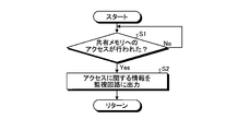
次に、図2を参照して、第1実施形態による制御装置100のスレーブ装置30の診断回路33が実行する処理フローについて説明する。
この処理フローでは、図2に示すように、診断回路33は、まず、ステップS1において、スレーブ装置30のCPU31によって共有メモリ11へのアクセスが行われたか否かを判断する。より具体的には、診断回路33は、CPU31と共有メモリ11との間のバス(図1の矢印付きの直線L参照)を監視し、CPU31が共有メモリ11にアクセスしたことを示す信号がバス上に出力されたか否かを判断する。このステップS1の処理は、CPU31によって共有メモリ11へのアクセスが行われたと判断されるまで繰り返される。ステップS1において、CPU31によって共有メモリ11へのアクセスが行われたと判断された場合には、ステップS2に処理が進む。
ステップS2において、診断回路33は、CPU31が行った共有メモリ11へのアクセスに関する情報をマザーボード10の監視回路13に出力する。ここで、アクセスに関する情報とは、CPU31がアクセスした共有メモリ11のアドレスを示す情報や、CPU31が行ったアクセスがデータの書き込みであるかデータの読み出しであるかを示す情報などを含む。アクセスに関する情報は、CPU31と共有メモリ11との間のバス(図1の矢印付きの直線L参照)から傍受される信号に基づいて生成される。そして、処理が戻る。
次に、図3を参照して、第1実施形態による制御装置100のマザーボード10の監視回路13が実行する処理フローについて説明する。
この処理フローでは、図3に示すように、監視回路13は、まず、ステップS11において、スレーブ装置30のCPU31が行った共有メモリ11へのアクセスに関する情報が診断回路33から入力されたか否かを判断する。このステップS11の処理は、アクセスに関する情報が診断回路33から入力されたと判断されるまで繰り返される。ステップS11において、アクセスに関する情報が診断回路33から入力されたと判断された場合には、ステップS12に処理が進む。
ステップS12において、監視回路13は、診断回路33から入力されたアクセスに関する情報を、マスタ装置20のレジスタ22に出力する。たとえばスレーブ装置30のCPU31が共有メモリ11にデータを書き込んだ場合、監視回路13は、CPU31が共有メモリ11のどのアドレスにデータを書き込んだかを特定することが可能な情報などをレジスタ22に書き込む。そして、処理が戻る。
次に、図4を参照して、第1実施形態による制御装置100のマスタ装置20のCPU21が実行する処理フローについて説明する。
この処理フローでは、図4に示すように、CPU21は、まず、ステップS21において、CPU31が行った共有メモリ11へのアクセスに関する情報がレジスタ22に記憶されたか否かを判断する。たとえば、レジスタ22が、アクセスに関する情報が記憶された場合にCPU21に割り込み信号を出力するように構成されているものとすると、CPU21は、ステップS21において、レジスタ22からの割り込み信号が自身に入力されたか否かを判断する。このステップS21の処理は、アクセスに関する情報がレジスタ22に記憶されたと判断されるまで繰り返される。ステップS21において、アクセスに関する情報がレジスタ22に記憶されたと判断された場合には、ステップS22に処理が進む。
ステップS22において、CPU21は、レジスタ22に記憶された情報に基づいて、共有メモリ11にアクセスする。たとえば、CPU31がマスタ装置20にデータを渡すために共有メモリ11にデータを書き込んだ場合、レジスタ22には、CPU31がデータを書き込んだ共有メモリ11のアドレスを特定することが可能な情報などが監視回路13によって書き込まれるので、CPU21は、ステップS22において、監視回路13によってレジスタ22に書き込まれた情報をレジスタ22から読み出し、読み出した情報に基づいて共有メモリ11にアクセスすることにより、CPU31が共有メモリ11に書き込んだデータを共有メモリ11から取得する。そして、処理が戻る。
以上説明したように、第1実施形態による制御装置100は、スレーブ装置30のCPU31が共有メモリ11へのアクセスを行った場合に、当該アクセスに関する情報をスレーブ装置30から取得し、取得したアクセスに関する情報をマスタ装置20に出力する監視回路13を備えている。これにより、共有メモリ11からデータを取得するために、共有メモリ11に定期的に繰り返しアクセスする処理などを行う必要がないため、共有メモリ11を介してデータを送受信する際の処理負担を軽減することができる。この結果、マザーボード10上のデータ負荷を軽減することができ、制御装置100全体の性能を向上させることができる。
また、第1実施形態によるスレーブ装置30は、CPU31と共有メモリ11との間のバス(図1の矢印付きの直線L参照)を監視することによりアクセスに関する情報を取得し、取得したアクセスに関する情報を監視回路13に出力する診断回路33を備えている。これにより、CPU31と共有メモリ11との間のバスに出力される信号を診断回路33によって傍受するだけで、アクセスに関する情報を容易に取得することができる。つまり、アクセスに関する情報を監視回路13に出力する処理をCPU31に行わせる必要がないので、CPU31の処理負担を軽減することができる。
また、第1実施形態によるマスタ装置20は、監視回路13から取得されたアクセスに関する情報を記憶するレジスタ22を備えており、マスタ装置20のCPU21は、レジスタ22に基づいて共有メモリ11にアクセスするように構成されている。これにより、レジスタ22を監視するだけで、スレーブ装置30のCPU31が共有メモリ11に行ったアクセスに関する情報を容易に取得することができる。これにより、共有メモリ11へのアクセスを効率的に行うことができる。
(第2実施形態)
次に、図5を参照して、第2実施形態による制御装置100aの構成について説明する。なお、第1実施形態と同様の構成要素については、同一の符号を割り当てて説明を省略する。
次に、図5を参照して、第2実施形態による制御装置100aの構成について説明する。なお、第1実施形態と同様の構成要素については、同一の符号を割り当てて説明を省略する。
図5に示すように、第2実施形態による制御装置100aは、第1実施形態による制御装置100と同様に、マザーボード10aと、マスタ装置20aと、複数のスレーブ装置30aとを備える。マスタ装置20aは、「第1装置」の一例であり、スレーブ装置30aは、「第2装置」の一例である。図5には、スレーブ装置30aが3つ設けられた例を示したが、スレーブ装置30aの数は、4つ以上であってもよいし、2つ以下であってもよい。
第2実施形態によるマザーボード10aは、共有メモリ11と、調停回路12と、監視回路13aとを備える。監視回路13aは、「第1回路」の一例である。また、第2実施形態によるマスタ装置20aは、CPU21aと、レジスタ22とを備える。CPU21aは、「第1制御部」の一例である。また、第2実施形態によるスレーブ装置30aは、CPU31aと、周辺デバイス32と、診断回路33aとを備える。CPU31aは、「第2制御部」の一例であるとともに、診断回路33aは、「第2回路」の一例である。
ここで、第2実施形態による診断回路33aは、CPU31aと共有メモリ11との間のバス(図5の矢印付きの直線L参照)を監視することにより、CPU31aに発生し得るエラーに関する情報を取得するように構成されている。
たとえば、CPU31aが複数のタスクA、B、CおよびDをこの順番で繰り返し実行する動作を行うように設定されている場合、診断回路33aは、CPU31aからの出力信号を上記のバス(図5の矢印付きの直線L参照)を介して傍受することにより、CPU31aが上記の設定から外れた動作を行っているか否かを判定するように構成されている。そして、診断回路33aは、CPU31aが上記の設定から外れた動作を行っていると判定した場合、すなわちCPU31aに何らかのエラーが発生したと判断した場合に、そのエラーの詳細をエラーログ34として記録するとともに、そのエラーに関する情報をマザーボード10aの監視回路13aに出力するように構成されている。
第2実施形態による監視回路13aは、上記エラーに関する情報をスレーブ装置30aから取得した場合に、取得したエラーに関する情報をマスタ装置20aに出力するように構成されている。より具体的には、監視回路13aは、上記エラーに関する情報をスレーブ装置30aから取得した場合に、どのスレーブ装置30aのCPU31aにエラーが発生したかを特定することが可能な情報をマスタ装置20aのレジスタ22に書き込むように構成されている。
第2実施形態によるCPU21aは、レジスタ22に基づいて例外処理をおこなうように構成されている。より具体的には、レジスタ22は、上記のような情報が診断回路33aにより書き込まれた場合に、CPU21aに割り込み信号を出力するように構成されている。そして、CPU21aは、レジスタ22から割り込み信号が入力された場合に、現在行っている処理を一旦停止して例外処理を行うように構成されている。なお、例外処理の例としては、エラーが発生したCPU31aを備えたスレーブ装置30aを初期化する処理や、エラーが発生したCPU31aを備えたスレーブ装置30aをシステムから切り離す処理などが考えられる。
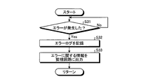
次に、図6を参照して、第2実施形態による制御装置100aのスレーブ装置30aの診断回路33aが実行する処理フローについて説明する。
この処理フローでは、図6に示すように、診断回路33aは、まず、ステップS31において、スレーブ装置30aのCPU31aにエラーが発生したか否かを判断する。より具体的には、診断回路33aは、CPU31aと共有メモリ11との間のバス(図5の矢印付きの直線L参照)を監視し、CPU31aからの出力信号をバスから傍受することにより、CPU31aが設定から外れた動作を行っているか否かを判定する。このステップS31の処理は、CPU31aにエラーが発生したと判断されるまで繰り返される。ステップS31において、CPU31aにエラーが発生したと判断された場合には、ステップS32に処理が進む。
ステップS32において、診断回路33aは、CPU31aに発生したエラーの詳細を示すエラーログ34を記録する。そして、ステップS33に処理が進む。
ステップS33において、診断回路33aは、CPU31aに発生したエラーに関する情報をマザーボード10aの監視回路13aに出力する。エラーに関する情報は、CPU31aと共有メモリ11との間のバス(図5の矢印付きの直線L参照)から傍受された信号に基づいて生成される。そして、処理が戻る。
次に、図7を参照して、第2実施形態による制御装置100aのマザーボード10aの監視回路13aが実行する処理フローについて説明する。
この処理フローでは、図7に示すように、監視回路13aは、まず、ステップS41において、スレーブ装置30aのCPU31aに発生したエラーに関する情報が診断回路33aから入力されたか否かを判断する。このステップS41の処理は、エラーに関する情報が診断回路33aから入力されたと判断されるまで繰り返される。ステップS41において、エラーに関する情報が診断回路33aから入力されたと判断された場合には、ステップS42に処理が進む。
ステップS42において、監視回路13aは、診断回路33aから入力されたエラーに関する情報を、マスタ装置20aのレジスタ22に出力する。より具体的には、監視回路13aは、どのスレーブ装置30aのCPU31aにエラーが発生したかを特定することが可能な情報をレジスタ22に書き込む。そして、処理が戻る。
次に、図8を参照して、第2実施形態による制御装置100aのマスタ装置20aのCPU21aが実行する処理フローについて説明する。
この処理フローでは、図8に示すように、CPU21aは、まず、ステップS51において、CPU31aに発生したエラーに関する情報がレジスタ22に記憶されたか否かを判断する。たとえば、レジスタ22が、エラーに関する情報が記憶された場合にCPU21aに割り込み信号を出力するように構成されているものとすると、CPU21aは、ステップS51において、レジスタ22からの割り込み信号が自身に入力されたか否かを判断する。このステップS51の処理は、エラーに関する情報がレジスタ22に記憶されたと判断されるまで繰り返される。ステップS51において、エラーに関する情報がレジスタ22に記憶されたと判断された場合には、ステップS52に処理が進む。
ステップS52において、CPU21aは、レジスタ22に記憶されたエラーに関する情報に基づいて、例外処理を実行する。つまり、CPU31aにエラーが発生した場合、レジスタ22には、どのスレーブ装置30aのCPU31aにエラーが発生したかを特定することが可能な情報が監視回路13aによって書き込まれるので、CPU21aは、ステップS52において、監視回路13aによってレジスタ22に書き込まれた情報をレジスタ22から読み出し、読み出した情報に基づいて特定したCPU31aを有するスレーブ装置30aに対して例外処理を行う。なお、例外処理の例としては、上記のように、エラーが発生したCPU31aを備えたスレーブ装置30aを初期化する処理や、エラーが発生したCPU31aを備えたスレーブ装置30aをシステムから切り離す処理などが考えられる。そして、処理が戻る。
以上説明したように、第2実施形態による制御装置100aは、スレーブ装置30aのCPU31aにエラーが発生した場合に、当該エラーに関する情報をスレーブ装置30aから取得し、取得したエラーに関する情報をマスタ装置20aに出力する監視回路13aを備えている。これにより、互いにエラーが発生しているか否かを検知する際の処理負担を軽減することができる。
つまり、プロセッサが複数設けられた従来の制御装置では、各プロセッサは、ある共通の記憶媒体(共有メモリ)を用いたいわゆるヘルシーカウンタなどを用いて互いにエラーが発生しているか否かを検知していた。たとえば、各プロセッサは、予め設定されたタスクが正常に終了する毎に、自身にエラーが発生していない旨を示すデータを共有メモリに記憶し、このように記憶したデータを互いに監視することにより、互いにエラーが発生しているか否かを検知していた。このように、従来では、各プロセッサは、互いにエラーが発生しているか否かを検知するために、予め設定されたタスクの他にも種々の処理を行う必要があったため、処理負担が増大することがあった。
これに対して、第2実施形態による制御装置100aは、上記のような監視回路13aを備えているので、CPU31aにエラーが発生した旨がCPU31aとは独立したハードウェアである監視回路13aによってマスタ装置20aに通知される。したがって、第2実施形態によれば、互いにエラーが発生しているか否かを検知するために、共有メモリ11に定期的に繰り返しアクセスする処理などを行う必要がないので、処理負担を軽減することができる。
また、第2実施形態によるスレーブ装置30aは、CPU31aと共有メモリ11との間のバス(図5の矢印付きの直線L参照)を監視することによりエラーに関する情報を取得し、取得したエラーに関する情報を監視回路13aに出力する診断回路33aを備えている。これにより、CPU31aと共有メモリ11との間のバスに出力される信号を診断回路33aによって傍受するだけで、エラーに関する情報を容易に取得することができる。つまり、エラーに関する情報を監視回路13aに出力する処理をCPU31aに行わせる必要がないので、CPU31aの処理負担を軽減することができる。また、CPU31aと共有メモリ11との間のバスに出力される信号を診断回路33aによって傍受することにより、CPU31aがどのような動作を行った際にエラーが発生したかをエラーログ34として詳細に記録することができる。
また、第2実施形態によるマスタ装置20aは、監視回路13aから取得されたエラーに関する情報を記憶するレジスタ22を備えており、CPU21aは、レジスタ22に基づいて例外処理を実行するように構成されている。これにより、レジスタ22を監視するだけで、エラーに関する情報を容易に取得することができる。
以上、本発明の実施形態を説明したが、上記実施形態はあくまで一例であって、発明の範囲を限定することは意図していない。上記実施形態は、様々な形態で実施されることが可能であり、発明の要旨を逸脱しない範囲で、種々の省略、置き換え、変更を行うことができる。上記実施形態やその変形は、発明の範囲や要旨に含まれるとともに、請求の範囲に記載された発明とその均等の範囲に含まれる。
Claims (6)
- 第1制御部を備えた第1装置と、
第2制御部を備えた第2装置と、
前記第1装置および前記第2装置によって共有される共有メモリと、
前記第2制御部が前記共有メモリへのアクセスを行った場合に、前記アクセスに関する情報を前記第2装置から取得し、取得した前記アクセスに関する情報を前記第1装置に出力する第1回路とを備える、制御装置。 - 前記第2装置は、前記第2制御部と前記共有メモリとの間のバスを監視することにより前記アクセスに関する情報を取得し、取得した前記アクセスに関する情報を前記第1回路に出力する第2回路をさらに備える、請求項1に記載の制御装置。
- 前記第1装置は、前記第1回路から取得された前記アクセスに関する情報を記憶するレジスタをさらに備え、
前記第1制御部は、前記レジスタに記憶された前記アクセスに関する情報に基づいて前記共有メモリにアクセスするように構成されている、請求項1に記載の制御装置。 - 第1制御部を備えた第1装置と、
第2制御部を備えた第2装置と、
前記第1制御部と前記第2制御部とによって共有される共有メモリと、
前記第2制御部にエラーが発生した場合に、前記エラーに関する情報を前記第2装置から取得し、取得した前記エラーに関する情報を前記第1装置に出力する第1回路とを備える、制御装置。 - 前記第2装置は、前記第2制御部と前記共有メモリとの間のバスを監視することにより前記エラーに関する情報を取得し、取得した前記エラーに関する情報を前記第1回路に出力する第2回路をさらに備える、請求項4に記載の制御装置。
- 前記第1装置は、前記第1回路から取得された前記エラーに関する情報を記憶するレジスタをさらに備え、
前記第1制御部は、前記レジスタに記憶された前記エラーに関する情報に基づいて例外処理を実行するように構成されている、請求項4に記載の制御装置。
Priority Applications (3)
| Application Number | Priority Date | Filing Date | Title |
|---|---|---|---|
| US15/511,201 US20190012292A1 (en) | 2016-03-22 | 2016-03-22 | Control device |
| PCT/JP2016/058928 WO2017163302A1 (ja) | 2016-03-22 | 2016-03-22 | 制御装置 |
| CN201680002199.9A CN107835990A (zh) | 2016-03-22 | 2016-03-22 | 控制装置 |
Applications Claiming Priority (1)
| Application Number | Priority Date | Filing Date | Title |
|---|---|---|---|
| PCT/JP2016/058928 WO2017163302A1 (ja) | 2016-03-22 | 2016-03-22 | 制御装置 |
Publications (1)
| Publication Number | Publication Date |
|---|---|
| WO2017163302A1 true WO2017163302A1 (ja) | 2017-09-28 |
Family
ID=59900040
Family Applications (1)
| Application Number | Title | Priority Date | Filing Date |
|---|---|---|---|
| PCT/JP2016/058928 WO2017163302A1 (ja) | 2016-03-22 | 2016-03-22 | 制御装置 |
Country Status (3)
| Country | Link |
|---|---|
| US (1) | US20190012292A1 (ja) |
| CN (1) | CN107835990A (ja) |
| WO (1) | WO2017163302A1 (ja) |
Families Citing this family (1)
| Publication number | Priority date | Publication date | Assignee | Title |
|---|---|---|---|---|
| EP4213024A1 (fr) * | 2022-01-12 | 2023-07-19 | Bull SAS | Procédé de partage d'image, programme d'ordinateur et système mettant en oeuvre un tel procédé |
Citations (5)
| Publication number | Priority date | Publication date | Assignee | Title |
|---|---|---|---|---|
| JPS5537643A (en) * | 1978-09-08 | 1980-03-15 | Fujitsu Ltd | Multiprocessor system trouble processing system |
| JPH0384640A (ja) * | 1989-08-29 | 1991-04-10 | Fujitsu Ltd | 障害情報通知方式 |
| JP2004078683A (ja) * | 2002-08-20 | 2004-03-11 | Toshiba Corp | コンピュータシステムおよび共有メモリ制御方法 |
| JP2014026347A (ja) * | 2012-07-24 | 2014-02-06 | Auto Network Gijutsu Kenkyusho:Kk | 監視装置、コンピュータプログラム及び監視方法 |
| JP2016066273A (ja) * | 2014-09-25 | 2016-04-28 | 株式会社東芝 | 制御装置 |
-
2016
- 2016-03-22 CN CN201680002199.9A patent/CN107835990A/zh not_active Withdrawn
- 2016-03-22 US US15/511,201 patent/US20190012292A1/en not_active Abandoned
- 2016-03-22 WO PCT/JP2016/058928 patent/WO2017163302A1/ja active Application Filing
Patent Citations (5)
| Publication number | Priority date | Publication date | Assignee | Title |
|---|---|---|---|---|
| JPS5537643A (en) * | 1978-09-08 | 1980-03-15 | Fujitsu Ltd | Multiprocessor system trouble processing system |
| JPH0384640A (ja) * | 1989-08-29 | 1991-04-10 | Fujitsu Ltd | 障害情報通知方式 |
| JP2004078683A (ja) * | 2002-08-20 | 2004-03-11 | Toshiba Corp | コンピュータシステムおよび共有メモリ制御方法 |
| JP2014026347A (ja) * | 2012-07-24 | 2014-02-06 | Auto Network Gijutsu Kenkyusho:Kk | 監視装置、コンピュータプログラム及び監視方法 |
| JP2016066273A (ja) * | 2014-09-25 | 2016-04-28 | 株式会社東芝 | 制御装置 |
Also Published As
| Publication number | Publication date |
|---|---|
| CN107835990A (zh) | 2018-03-23 |
| US20190012292A1 (en) | 2019-01-10 |
Similar Documents
| Publication | Publication Date | Title |
|---|---|---|
| US8874959B2 (en) | Information processing apparatus, image forming apparatus, and information processing program | |
| US8645767B2 (en) | Scalable I/O adapter function level error detection, isolation, and reporting | |
| US8661306B2 (en) | Baseboard management controller and memory error detection method of computing device utilized thereby | |
| CN109977061A (zh) | 一种中断处理方法及中断处理装置 | |
| CN105373345B (zh) | 存储器设备和模块 | |
| CN115934389A (zh) | 用于错误报告和处理的系统和方法 | |
| WO2016127600A1 (zh) | 异常处理方法及装置 | |
| WO2017163302A1 (ja) | 制御装置 | |
| JP2016066273A (ja) | 制御装置 | |
| JP6241323B2 (ja) | スイッチ装置、情報処理装置、情報処理装置の制御方法および情報処理装置の制御プログラム | |
| US8032720B2 (en) | Memory access monitoring apparatus and related method | |
| JP2013238926A (ja) | 信号処理回路およびそれを用いた試験装置 | |
| US10210110B2 (en) | Associating data buses and management bus connections for peripheral devices | |
| JP2012163995A (ja) | 情報処理装置 | |
| JP2005149503A (ja) | Dmaを使用してメモリをテストするためのシステムおよび方法 | |
| US20110145655A1 (en) | Input/output hub to input/output device communication | |
| US20160077942A1 (en) | Storage system and test method for testing pci express interface | |
| US10191481B2 (en) | Numerical controller and numerical control system in which the controller is connected by network | |
| JP2008152665A (ja) | 半導体集積回路の動作解析方法 | |
| US20140052950A1 (en) | System controlling apparatus, information processing system, and controlling method of system controlling apparatus | |
| WO2018179753A1 (ja) | マイクロコンピュータ | |
| US20200183803A1 (en) | System For Completely Testing Communication Links Inside Processor According To Processor Information And Method Thereof | |
| JP6383112B2 (ja) | 制御装置 | |
| JP6535516B2 (ja) | マルチ・プログラマブルデバイス・システムとその制御方法 | |
| JP2015187833A (ja) | 情報処理装置、情報処理方法およびプログラム |
Legal Events
| Date | Code | Title | Description |
|---|---|---|---|
| NENP | Non-entry into the national phase |
Ref country code: DE |
|
| 121 | Ep: the epo has been informed by wipo that ep was designated in this application |
Ref document number: 16895338 Country of ref document: EP Kind code of ref document: A1 |
|
| 122 | Ep: pct application non-entry in european phase |
Ref document number: 16895338 Country of ref document: EP Kind code of ref document: A1 |
|
| NENP | Non-entry into the national phase |
Ref country code: JP |