WO2017159772A1 - Machining time prediction device, cutting system, and machining time prediction method - Google Patents
Machining time prediction device, cutting system, and machining time prediction method Download PDFInfo
- Publication number
- WO2017159772A1 WO2017159772A1 PCT/JP2017/010589 JP2017010589W WO2017159772A1 WO 2017159772 A1 WO2017159772 A1 WO 2017159772A1 JP 2017010589 W JP2017010589 W JP 2017010589W WO 2017159772 A1 WO2017159772 A1 WO 2017159772A1
- Authority
- WO
- WIPO (PCT)
- Prior art keywords
- machining
- unit
- control
- time
- machining time
- Prior art date
Links
Images

Classifications
-
- G—PHYSICS
- G05—CONTROLLING; REGULATING
- G05B—CONTROL OR REGULATING SYSTEMS IN GENERAL; FUNCTIONAL ELEMENTS OF SUCH SYSTEMS; MONITORING OR TESTING ARRANGEMENTS FOR SUCH SYSTEMS OR ELEMENTS
- G05B19/00—Programme-control systems
- G05B19/02—Programme-control systems electric
- G05B19/18—Numerical control [NC], i.e. automatically operating machines, in particular machine tools, e.g. in a manufacturing environment, so as to execute positioning, movement or co-ordinated operations by means of programme data in numerical form
- G05B19/406—Numerical control [NC], i.e. automatically operating machines, in particular machine tools, e.g. in a manufacturing environment, so as to execute positioning, movement or co-ordinated operations by means of programme data in numerical form characterised by monitoring or safety
- G05B19/4069—Simulating machining process on screen
-
- B—PERFORMING OPERATIONS; TRANSPORTING
- B23—MACHINE TOOLS; METAL-WORKING NOT OTHERWISE PROVIDED FOR
- B23Q—DETAILS, COMPONENTS, OR ACCESSORIES FOR MACHINE TOOLS, e.g. ARRANGEMENTS FOR COPYING OR CONTROLLING; MACHINE TOOLS IN GENERAL CHARACTERISED BY THE CONSTRUCTION OF PARTICULAR DETAILS OR COMPONENTS; COMBINATIONS OR ASSOCIATIONS OF METAL-WORKING MACHINES, NOT DIRECTED TO A PARTICULAR RESULT
- B23Q17/00—Arrangements for observing, indicating or measuring on machine tools
- B23Q17/09—Arrangements for observing, indicating or measuring on machine tools for indicating or measuring cutting pressure or for determining cutting-tool condition, e.g. cutting ability, load on tool
-
- G—PHYSICS
- G05—CONTROLLING; REGULATING
- G05B—CONTROL OR REGULATING SYSTEMS IN GENERAL; FUNCTIONAL ELEMENTS OF SUCH SYSTEMS; MONITORING OR TESTING ARRANGEMENTS FOR SUCH SYSTEMS OR ELEMENTS
- G05B19/00—Programme-control systems
- G05B19/02—Programme-control systems electric
- G05B19/18—Numerical control [NC], i.e. automatically operating machines, in particular machine tools, e.g. in a manufacturing environment, so as to execute positioning, movement or co-ordinated operations by means of programme data in numerical form
- G05B19/19—Numerical control [NC], i.e. automatically operating machines, in particular machine tools, e.g. in a manufacturing environment, so as to execute positioning, movement or co-ordinated operations by means of programme data in numerical form characterised by positioning or contouring control systems, e.g. to control position from one programmed point to another or to control movement along a programmed continuous path
-
- G—PHYSICS
- G05—CONTROLLING; REGULATING
- G05B—CONTROL OR REGULATING SYSTEMS IN GENERAL; FUNCTIONAL ELEMENTS OF SUCH SYSTEMS; MONITORING OR TESTING ARRANGEMENTS FOR SUCH SYSTEMS OR ELEMENTS
- G05B19/00—Programme-control systems
- G05B19/02—Programme-control systems electric
- G05B19/18—Numerical control [NC], i.e. automatically operating machines, in particular machine tools, e.g. in a manufacturing environment, so as to execute positioning, movement or co-ordinated operations by means of programme data in numerical form
- G05B19/406—Numerical control [NC], i.e. automatically operating machines, in particular machine tools, e.g. in a manufacturing environment, so as to execute positioning, movement or co-ordinated operations by means of programme data in numerical form characterised by monitoring or safety
- G05B19/4063—Monitoring general control system
-
- G—PHYSICS
- G05—CONTROLLING; REGULATING
- G05B—CONTROL OR REGULATING SYSTEMS IN GENERAL; FUNCTIONAL ELEMENTS OF SUCH SYSTEMS; MONITORING OR TESTING ARRANGEMENTS FOR SUCH SYSTEMS OR ELEMENTS
- G05B19/00—Programme-control systems
- G05B19/02—Programme-control systems electric
- G05B19/18—Numerical control [NC], i.e. automatically operating machines, in particular machine tools, e.g. in a manufacturing environment, so as to execute positioning, movement or co-ordinated operations by means of programme data in numerical form
- G05B19/4155—Numerical control [NC], i.e. automatically operating machines, in particular machine tools, e.g. in a manufacturing environment, so as to execute positioning, movement or co-ordinated operations by means of programme data in numerical form characterised by programme execution, i.e. part programme or machine function execution, e.g. selection of a programme
-
- G—PHYSICS
- G05—CONTROLLING; REGULATING
- G05B—CONTROL OR REGULATING SYSTEMS IN GENERAL; FUNCTIONAL ELEMENTS OF SUCH SYSTEMS; MONITORING OR TESTING ARRANGEMENTS FOR SUCH SYSTEMS OR ELEMENTS
- G05B2219/00—Program-control systems
- G05B2219/30—Nc systems
- G05B2219/31—From computer integrated manufacturing till monitoring
- G05B2219/31407—Machining, work, process finish time estimation, calculation
-
- G—PHYSICS
- G05—CONTROLLING; REGULATING
- G05B—CONTROL OR REGULATING SYSTEMS IN GENERAL; FUNCTIONAL ELEMENTS OF SUCH SYSTEMS; MONITORING OR TESTING ARRANGEMENTS FOR SUCH SYSTEMS OR ELEMENTS
- G05B2219/00—Program-control systems
- G05B2219/30—Nc systems
- G05B2219/34—Director, elements to supervisory
- G05B2219/34494—Display machining time and real time clock to control machining time
-
- G—PHYSICS
- G05—CONTROLLING; REGULATING
- G05B—CONTROL OR REGULATING SYSTEMS IN GENERAL; FUNCTIONAL ELEMENTS OF SUCH SYSTEMS; MONITORING OR TESTING ARRANGEMENTS FOR SUCH SYSTEMS OR ELEMENTS
- G05B2219/00—Program-control systems
- G05B2219/30—Nc systems
- G05B2219/36—Nc in input of data, input key till input tape
- G05B2219/36219—Calculate machining information, like time, surface to be machined from program
Definitions
- the present invention relates to a machining time prediction device, a cutting system, and a machining time prediction method.
- a cutting machine that cuts a workpiece with a rotating processing tool.
- a machining program having a plurality of machining steps is created in advance. Then, based on each machining step of the machining program, the relative positional relationship between the workpiece and the machining tool is changed in three dimensions, and the machining tool is brought into contact with the workpiece at a predetermined angle. The workpiece is cut into a desired shape.
- the remaining processing time required to cut the workpiece is predicted.
- the machining time required from the time when cutting is started to the current time of cutting is measured, and the current machining process is performed at any point in the machining program. It is discriminated whether it is a process. Then, the remaining time required for cutting is predicted from the measurement result and the discrimination result.
- the present invention has been made in view of the above points, and an object of the present invention is to provide a processing time prediction device, a cutting system, and a processing time prediction method with high prediction accuracy when predicting the remaining processing time required for cutting. It is to be.
- a machining time prediction apparatus includes a spindle that rotates a machining tool, a holding unit that holds a workpiece and is movable relative to the spindle, and records a plurality of machining steps.
- the cutting machine which cuts the said workpiece using the said processing tool based on a processing program, it is a processing time prediction apparatus which estimates the remaining processing time which cuts the said workpiece.
- the processing time prediction device includes a display screen and a control device connected to the display screen.
- the control device includes a storage unit, a simulation unit, a machining time calculation unit, a machining time acquisition unit, and a display unit.
- the processing program is stored in the storage unit.
- the simulation unit performs a simulation of cutting the workpiece by the cutting machine according to the machining program, and creates a control pattern in which control information of the spindle and the holding unit is recorded.
- the machining time calculation unit calculates a remaining machining time in each process of the machining program based on the control pattern, and creates a machining time table in which the remaining machining time for each process of the machining program is recorded.
- the machining time acquisition unit acquires a process of the machining program that is currently being cut by the cutting machine, and acquires a remaining machining time for the acquired process of the machining program from the machining time table.
- the display unit displays the remaining processing time acquired by the processing time acquisition unit on the display screen.
- each step of cutting a workpiece by the cutting machine according to a machining program that is actually used by the cutting machine by the simulation unit, and each step that the cutting machine actually performs Is performed in a pseudo manner, and a control pattern is created.
- the control pattern created by the simulation unit is the same as the control pattern created when the cutting machine performs cutting. Therefore, the remaining machining time in each process in the machining time table created based on the control pattern created by the simulation unit is substantially the same as the remaining machining time actually required in each process performed by the cutting machine. become.
- the error can be further reduced between the remaining machining time predicted by the machining time prediction apparatus and the remaining machining time actually required. . Therefore, the remaining machining time with high accuracy can be predicted.
- a machining time prediction method includes a spindle that rotates a machining tool, and a holding unit that holds a workpiece and is movable relative to the spindle, and records a plurality of machining steps.
- the machining time prediction method includes a simulation process, a machining time calculation process, a machining time acquisition process, and a display process.
- the cutting machine performs a simulation of cutting the workpiece in accordance with the machining program, and creates a control pattern in which control information of the spindle and the holding unit is recorded.
- machining time calculation step a remaining machining time in each step of the machining program is calculated based on the control pattern, and a machining time table in which the remaining machining time for each step of the machining program is recorded is created.
- the machining time acquisition step the process of the machining program currently being cut by the cutting machine is acquired, and the remaining machining time for the acquired process of the machining program is acquired from the machining time table.
- the display step the remaining processing time acquired in the processing time acquisition step is displayed on a display screen.
- machining time prediction device it is possible to provide a machining time prediction device, a cutting system, and a machining time prediction method with high prediction accuracy when the remaining machining time required for cutting is predicted.
- FIG. 1 is a block diagram illustrating a cutting system according to an embodiment.
- FIG. 2 is a perspective view showing the cutting machine according to the embodiment.
- FIG. 3 is a perspective view showing the holding unit and the tool magazine.
- FIG. 4 is a front view showing the spindle and the tool magazine.
- FIG. 5 is a block diagram showing a cutting machine.
- FIG. 6A is a diagram showing an example of the relationship between the elapsed time when the spindle moves and the moving speed of the spindle before the S-shaped acceleration control is performed, and FIG. It is the figure which showed an example of the relationship between the elapsed time when a spindle moves, and the moving speed of a spindle after character acceleration control was performed.
- FIG. 6A is a diagram showing an example of the relationship between the elapsed time when the spindle moves and the moving speed of the spindle before the S-shaped acceleration control is performed
- FIG. It is the figure which showed an example of the relationship between the elapse
- FIG. 7A is a diagram illustrating an example of the change in the spindle position before the smoothing control is performed.
- FIG. 7B is a diagram illustrating the change in the spindle position after the smoothing control is performed. It is the figure which showed an example.
- FIG. 8 is a block diagram illustrating the machining time prediction apparatus according to the embodiment.
- FIG. 9 is a diagram showing the relationship between the data size of the processed machining program and the elapsed time.
- FIG. 10 is a flowchart showing a procedure for displaying the remaining machining time.
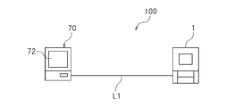
- FIG. 1 is a block diagram showing a cutting system 100 according to the present embodiment.
- a cutting system 100 according to the present embodiment includes a cutting machine 1 and a processing time prediction device 70.
- the cutting machine 1 will be described, and then the processing time prediction device 70 will be described.
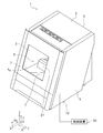
- FIG. 2 is a perspective view of the cutting machine 1.
- the axes orthogonal to each other are taken as an X axis, a Y axis, and a Z axis.
- the cutting machine 1 according to this embodiment is assumed to be placed on an XY plane composed of an X axis and a Y axis.
- the left side and the right side are the left side and the right side when the cutting machine 1 is viewed toward the front cover 7 in FIG. 2.
- the left is L
- the right is R
- the front is F
- the rear Re
- the upper U
- the lower D.
- these are only directions for convenience of explanation, and do not limit the installation mode of the cutting machine 1 at all.
- the cutting machine 1 is for cutting a workpiece 15 (see FIG. 3).
- the workpiece 15 is, for example, an artificial tooth material.
- the workpiece 15 is formed of a material such as ceramics or resin.
- the material of the workpiece 15 is not particularly limited.
- the cutting machine 1 is formed in a box shape.
- the cutting machine 1 includes a case 10 having a base portion 2, a left outer wall portion 3, a right outer wall portion 4, a top surface portion 5 and a rear surface portion 6, and a front cover 7.
- the front of the case 10 is opened.
- the left outer wall portion 3 extends upward at the left end of the base portion 2.
- the right outer wall portion 4 extends upward at the right end of the base portion 2.
- the rear surface portion 6 extends upward at the rear end of the base portion 2.
- the rear surface portion 6 is connected to the rear end of the left outer wall portion 3 and the rear end of the right outer wall portion 4.
- the top surface portion 5 is disposed above the base portion 2.
- the top surface portion 5 is connected to the upper end of the left outer wall portion 3, the upper end of the right outer wall portion 4, and the upper end of the rear surface portion 6.
- an internal space 8 is formed by the base portion 2, the left outer wall portion 3, the right outer wall portion 4, the top surface portion 5, and the rear surface portion 6.
- the internal space 8 is a processing area where cutting is performed on the workpiece 15 (see FIG. 3).
- the front cover 7 is configured to be opened and closed by moving in the vertical direction at the front end of the left outer wall 3 and the front end of the right outer wall 4.
- the front cover 7 is provided with a window portion 7a. The operator can visually recognize the internal space 8 from the window portion 7a.
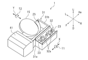
- FIG. 3 is a perspective view showing the holding unit 25 and the tool magazine 32.
- the cutting machine 1 is formed in a box-like holding unit 25 that holds the workpiece 15, a support unit 31 connected to the holding unit 25, and accommodates a plurality of processing tools 23.
- the tool magazine 32 is provided.
- the holding part 25, the support part 31, and the tool magazine 32 are provided in the internal space 8 (see FIG. 2).
- the shape of the workpiece 15 is a disk shape.
- the holding part 25 is formed in a shape capable of holding the workpiece 15, here, in a semicircular arc shape.
- a first rotating shaft is connected to the front portion of the holding portion 25, and a second rotating shaft is connected to the rear portion of the holding portion 25.
- the first rotation shaft is connected to a first drive unit 41 provided at the front portion of the holding unit 25.
- the first drive unit 41 is, for example, a motor.
- the first drive unit 41 rotates the first rotation axis in the direction T1 around the X axis.
- the holding unit 25 rotates in the direction T1.
- the workpiece 15 can be rotated in the direction T1.
- the support unit 31 is connected to the second drive unit 42 (see FIG.
- the second drive unit 42 and the third drive unit 43 are, for example, motors.
- the support portion 31 is formed in an L shape.
- the support portion 31 includes a first plate portion 31a formed extending in the X-axis direction, and a second plate portion 31b formed extending in the Y-axis direction from the rear end of the first plate portion 31a.
- the second plate portion 31b of the support portion 31 supports the second rotation shaft.
- a tool magazine 32 is fixed to the first plate portion 31 a of the support portion 31.
- a plurality of holes 32a are formed on the upper surface of the tool magazine 32, and the processing tool 23 is inserted into the holes 32a with the upper portion 23a (see FIG. 4) of the processing tool 23 exposed.
- the upper part 23a of the processing tool 23 is gripped by a spindle 33 (see FIG. 4) described later.
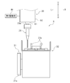
- FIG. 4 is a front view showing the spindle 33.
- the cutting machine 1 includes a spindle 33.
- a spindle 33 is provided so as to extend in the vertical direction.
- the spindle 33 grips the processing tool 23.
- the spindle 33 rotates the processing tool 23.
- the spindle 33 can be moved relative to the workpiece 15 in a three-dimensional direction.
- the spindle 33 moves relative to the workpiece 15 by moving the spindle 33 in a three-dimensional direction.
- the spindle 33 may be fixed and the workpiece 15 may move so that the spindle 33 moves relative to the workpiece 15.
- the spindle 33 is connected to the fourth drive unit 44.
- the spindle 33 is moved in the front-rear direction, the left-right direction, and the up-down direction by the fourth drive unit 44.
- the 4th drive part 44 is not specifically limited, For example, it is a motor.
- the spindle 33 includes a housing 60 and a grip portion 61 that grips the upper portion 23 a of the processing tool 23.
- the spindle 33 returns the currently held processing tool 23 to a predetermined position in the tool magazine 32. Thereafter, the spindle 33 moves so that the gripping portion 61 is positioned directly above the upper portion 23a of the processing tool 23 to be newly gripped.
- the spindle 33 moves downward toward the upper part 23a of the processing tool 23 with the gripping part 61 open, and grips the upper part 23a of the processing tool 23 by closing the gripping part 61. Thereafter, the spindle 33 moves toward the workpiece 15 (see FIG. 3) in order to start cutting.
- the spindle 33 is connected to a drive unit that rotates the processing tool 23 in a state where the spindle 33 holds the processing tool 23.
- FIG. 5 is a block diagram of the cutting machine 1.
- the cutting machine includes a control device 50.
- the control device 50 is built in the cutting machine 1.
- the arrangement position of the control device 50 is not particularly limited.
- the control device 50 is a computer, and includes a central processing unit (CPU), a ROM storing a program executed by the CPU, a RAM, and the like.
- the program stored in the ROM is so-called firmware.
- the control device 50 is connected to the first to fourth drive units 41 to 44 and the spindle 33.
- the control device 50 controls the rotation of the holding unit 25 in the direction T1 (see FIG. 3) around the X axis by controlling the first drive unit 41.
- the control device 50 controls the movement of the holding unit 25 in the front-rear direction by controlling the second drive unit 42.
- the control device 50 controls the rotation of the holding unit 25 in the direction T2 (see FIG. 3) around the Y axis by controlling the third driving unit 43.
- the control device 50 controls the movement of the spindle 33 in the front-rear direction and the left-right direction by controlling the fourth drive unit 44.
- the control device 50 controls the spindle 33 to control the rotation of the spindle 33 and control the grip of the processing tool 23 on the spindle 33.
- the cutting machine 1 produces a desired workpiece by cutting the workpiece 15 using a plurality of processing tools 23 based on a machining program.
- This machining program is so-called NC data (NC program).
- the machining program is a recording of a plurality of machining steps in which the operation of the spindle 33 and the operation of the holding unit 25 that holds the workpiece 15 are defined by coordinate values. That is, the machining program has a plurality of machining steps.
- the control device 50 controls the operation of the spindle 33 and the holding unit 25 according to the plurality of steps, whereby the workpiece 15 is cut by the processing tool 23 and a desired workpiece is produced.
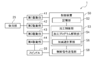
- the control device 50 includes a storage unit 52, a processing control unit 53, and a control signal transmission unit 58.
- the machining control unit 53 includes a machining program interpretation unit 54 and an acceleration / deceleration calculation unit 56.
- Each of these units is realized by a program stored in the ROM.
- This program is created by, for example, another personal computer. Then, the control device 50 and another personal computer are connected by a cable such as a USB, and the created program is transferred to the control device 50.
- the transferred program is stored in, for example, a ROM built in the CPU of the control device 50. However, this program may be read from a recording medium such as a CD (compact disc) or a DVD (digital versatile disc). Note that this program may be downloaded through the Internet.
- These units may be realized by a processor, a circuit, and the like.
- the storage unit 52 for example, the machining program, an acceleration parameter described later, an S-shaped acceleration parameter, a smoothing parameter, and the like are stored in advance.
- the machining control unit 53 performs control related to the machining of the workpiece 15.
- the machining control unit 53 creates a control pattern in which control information for the spindle 33 and the holding unit 25 is recorded in accordance with the machining program.
- the control related to the cutting by the machining control unit 53 is realized by the machining program interpretation unit 54 and the acceleration / deceleration calculation unit 56.
- the machining program interpretation unit 54 interprets the machining program stored in the storage unit 52. Specifically, the machining program interpretation unit 54 reads a machining program stored in the storage unit 52. Then, the machining program interpretation unit 54 calculates position information of the spindle 33 and the holding unit 25 in each process from the coordinate values in each process of the read machining program. This position information is obtained along a time series.
- the acceleration / deceleration calculation unit 56 is position information calculated by the machining program interpretation unit 54, and the spindle 33 controlled by the first to fourth drive units 41 to 44 from the position information of the spindle 33 and the holding unit 25 and A control pattern in which the control information of the holding unit 25 is recorded is calculated.
- This control pattern is a control pattern related to the first to fourth drive units 41 to 44, and is a control pattern in which control information for controlling the positions of the spindle 33 and the holding unit 25 is recorded.
- the acceleration / deceleration calculation unit 56 generates interrupts at predetermined intervals (for example, 250 ⁇ s), and moves between the first interrupt and the interrupt that occurs after the first interrupt.
- the movement angle of each motor of the fourth drive units 41 to 44 is calculated.
- the acceleration parameter stored in the storage unit 52 is used when creating the control pattern.
- this control pattern is a control pattern after S-shaped acceleration control and smoothing control are performed.
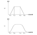
- FIG. 6A is a diagram showing an example of the relationship between the elapsed time when the spindle 33 moves in the internal space 8 and the moving speed of the spindle 33 before the S-shaped acceleration control is performed.
- FIG. 6B is a diagram illustrating a state after the S-shaped acceleration control is performed on the moving speed of the spindle 33 during the elapsed time in FIG. 6 (a) and 6 (b), the horizontal axis indicates the elapsed time, and the vertical axis indicates the speed.
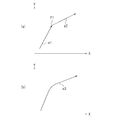
- FIG. 7A is a diagram illustrating an example of a change in the position of the spindle 33 before the smoothing control is performed.
- FIG. 7B is a diagram showing a change in the position of the spindle 33 after the smoothing control is performed with respect to the change in the position of the spindle 33 shown in FIG. 7A and 7B, the horizontal axis indicates the position of the spindle 33 in the X-axis direction, and the vertical axis indicates the position of the spindle 33 in the Y-axis direction. For example, it is assumed that the position of the spindle 33 changes along the control pattern as shown in FIG.
- the load applied to the spindle 33 increases. Therefore, as shown in FIG. 7B, by performing smoothing control, the positions of the paths a1 and a2 are corrected, and a smooth curved path a3 is obtained.
- the smoothing control is performed using a smoothing parameter stored in advance in the storage unit 52. A different value is set for this smoothing parameter depending on the model.
- the acceleration / deceleration calculation unit 56 can obtain a control pattern in which S-shaped acceleration control and smoothing control are performed.
- the control signal transmission unit 58 appropriately transmits a control signal to the first to fourth drive units 41 to 44 in accordance with the control pattern obtained by the acceleration / deceleration calculation unit 56.
- the first to fourth drive units 41 to 44 that have received the control signal control the angle of the motor in accordance with the control signal. Then, the workpiece 15 is cut by moving the spindle 33 and the holding unit 25 in accordance with the control pattern obtained by the acceleration / deceleration calculation unit 56, and a desired workpiece is produced.
- the processing time prediction device 70 is a device that predicts the remaining processing time required for the cutting machine 1 to cut the workpiece 15 (hereinafter simply referred to as “remaining processing time”). .
- the machining time prediction device 70 is connected to the cutting machine 1 by a line L1 so that wired communication is possible.
- the cutting machine 1 and the processing time prediction apparatus 70 may be connected so that wireless communication is possible.
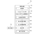
- FIG. 8 is a block diagram showing the machining time prediction device 70.
- the machining time prediction device 70 includes a display screen 72 and a control device 74.
- the display screen 72 is a display, for example, and displays the remaining time of cutting.
- the display screen 72 may be an operation screen (not shown) provided on the cutting machine 1 and allowing an operator to operate the cutting machine 1.
- the control device 74 is a computer, and includes a CPU, a ROM storing a program executed by the CPU, a RAM, and the like.
- the control device 74 includes a storage unit 82, a simulation unit 83, a machining time calculation unit 88, a machining time acquisition unit 89, a display unit 90, and an end determination unit 92.
- the simulation unit 83 includes a machining program interpretation unit 84 and an acceleration / deceleration calculation unit 86. Each of these units is realized by a program stored in the ROM. This program is read from a recording medium such as a CD or a DVD. Note that this program may be downloaded through the Internet.
- These units may be realized by a processor, a circuit, and the like.
- the storage unit 82 stores a machining program, an acceleration parameter, an S-shaped acceleration parameter, and a smoothing parameter.
- the machining program, the acceleration parameter, the S-shaped acceleration parameter, and the smoothing parameter stored in the storage unit 82 are the machining program, the acceleration parameter, the S-shaped acceleration parameter, and the smoothing parameter that are stored in the storage unit 52 of the cutting machine 1, respectively. It is the same as the smoothing parameter.
- storage part 52 of the control apparatus 50 of the cutting machine 1 may be a separate memory
- the simulation unit 83 simulates the cutting of the workpiece 15 (see FIG. 3) performed by the cutting machine 1.
- the simulation unit 83 performs a simulation in which the cutting machine 1 cuts the workpiece 15 according to the machining program stored in the storage unit 82, and the spindle 33 (see FIG. 4) and the holding unit 25 (see FIG. 3).
- the control pattern in which the control information is recorded is created.
- the simulation unit 83 performs pseudo control similar to the processing control unit 53 of the cutting machine 1 in the virtual space.
- the simulation unit 83 is realized by a machining program interpretation unit 84 and an acceleration / deceleration calculation unit 86.
- the machining program interpretation unit 84 of the simulation unit 83 of the machining time prediction device 70 performs the same control as the machining program interpretation unit 54 (see FIG. 5) of the machining control unit 53 of the cutting machine 1. To do. That is, the machining program interpretation unit 84 interprets the machining program and calculates position information of the spindle 33 and the holding unit 25 in each step of the machining program.
- the same source code as the machining program interpretation unit 54 of the cutting machine 1 is used as the source code of the machining program interpretation unit 84.
- the acceleration / deceleration calculation unit 86 of the simulation unit 83 performs the same control as the acceleration / deceleration calculation unit 56 of the machining control unit 53 of the cutting machine 1 in a pseudo manner. That is, the acceleration / deceleration calculation unit 86 creates a control pattern by calculating the acceleration when the spindle 33 and the holding unit 25 move from the position information calculated by the machining program interpretation unit 84.
- the source code of the acceleration / deceleration calculation unit 86 of the simulation unit 83 is the same source code as the acceleration / deceleration calculation unit 56 of the machining control unit 53. That is, the acceleration / deceleration calculation unit 86 of the simulation unit 83 can obtain a control pattern in which the above-described S-shaped acceleration control and the above-described smoothing control are performed.
- the machining time calculation unit 88 calculates the remaining machining time in each process of the machining program based on the control pattern created by the acceleration / deceleration calculation unit 56 of the simulation unit 83. Then, the machining time calculation unit 88 creates a machining time table in which the remaining machining time for each process of the machining program is recorded.
- FIG. 9 is a diagram showing the relationship between the data size of the processed machining program and the elapsed time. In FIG. 9, the horizontal axis represents the data size (number of bytes) of the processed machining program, and the vertical axis represents the elapsed time. Moreover, in FIG.
- the machining time calculation unit 88 creates a machining time table based on the graph as shown in FIG.
- the total data size of the machining program (total data size of the machining program) is size S21
- the total machining time required for cutting (total machining time required for cutting) is time T21.
- the data size of the processed machining program processed up to the predetermined process of the machining program during the cutting process is the size S22
- the machining time required until the predetermined process is time T22.
- the machining time calculation unit 88 calculates the data size of the processed machining program for each process of the machining program, and calculates the remaining machining time for each data size. Then, the machining time calculator 88 records the relationship between the processed data size and the remaining machining time in the machining table. The machining time calculation unit 88 creates such a machining table.
- the machining time acquisition unit 89 acquires a process of a machining program that is currently being cut by the cutting machine 1. Then, the machining time acquisition unit 89 acquires the remaining machining time for the process of the acquired machining program from the machining time table. A detailed procedure for acquiring the remaining machining time will be described later.
- the display unit 90 displays the remaining processing time acquired by the processing time acquisition unit 89 on the display screen 72.
- the end determination unit 92 determines whether or not the cutting of the workpiece 15 by the cutting machine 1 has ended. In other words, the end determination unit 92 determines whether or not to end the process of displaying the remaining machining time. A detailed procedure for determining whether or not the cutting of the workpiece 15 has been completed in the end determination unit 92 will be described later.
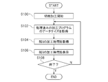
- FIG. 10 is a flowchart showing a procedure for displaying the remaining machining time.
- the procedure for displaying the remaining machining time will be described with reference to the flowchart of FIG.
- the machining time table is created by the simulation unit 83 of the machining time prediction device 70. This processing time table is assumed to be stored in the storage unit 82 of the processing time prediction device 70.
- step S ⁇ b> 100 the control device 50 of the cutting machine 1 starts cutting the workpiece 15 in accordance with the processing program stored in the storage unit 52.
- the control pattern after the S-shaped acceleration control and the smoothing control are performed by the acceleration / deceleration calculation unit 56 of the machining control unit 53 of the cutting machine 1 is created.
- the first to fourth drive units 41 to 44 are controlled to control the movement positions and movement speeds of the spindle 33 and the holding unit 25.
- step S100 after the cutting by the cutting machine 1 is started, in step S102, the machining time acquisition unit 89 of the machining time prediction device 70 receives the data of the processed machining program from the cutting machine 1 at the present time. Get the size.
- the machining time acquisition unit 89 transmits a data size acquisition signal to the control device 50 of the cutting machine 1.
- the control device 50 that has received the data size acquisition signal acquires the process of the machining program that is currently being performed, and calculates the data size of the machining program corresponding to the processed machining program of the machining program.
- the control device 50 of the cutting machine 1 transmits the data size of the processed machining program to the machining time acquisition unit 89 of the machining time prediction device 70.
- the machining time acquisition unit 89 acquires the data size of the processed machining program by receiving the data size of the processed machining program.
- step S104 the processing time acquisition unit 89 acquires the remaining processing time.
- the machining time acquisition unit 89 acquires the remaining machining time according to the data size of the processed machining program acquired in step S102.
- the storage unit 82 stores the processing time table created by the processing time calculation unit 88.
- the machining time acquisition unit 89 acquires the remaining machining time corresponding to the data size of the corresponding processed machining program from the machining time table created by the machining time calculation unit 88.
- step S106 the display unit 90 displays the remaining processing time acquired by the processing time acquisition unit 89 on the display screen 72.
- the end determination unit 92 determines whether or not the cutting process has ended.
- the total data size of the machining program is stored in advance in the storage unit 82 of the machining time prediction apparatus 70.
- the end determination unit 92 compares the total data size of the machining program stored in the storage unit 82 with the data size of the processed machining program acquired by the machining time acquisition unit 89 in step S102. At this time, when the data size of the processed machining program matches the total data size of the machining program, the end determination unit 92 determines that the cutting by the cutting machine 1 has ended.
- the display of the remaining machining time is terminated.
- the end determination unit 92 continues cutting by the cutting machine 1 It is determined that In this case, the process returns to step S102, and the step of acquiring the data size of the processed machining program is performed again.
- the cutting machine 1 causes the workpiece 15 (see FIG. 3) to be processed by the simulation unit 83 according to the machining program actually used by the cutting machine 1.
- a control pattern is created by performing each process of cutting, which is actually performed by the cutting machine 1 in a pseudo manner.
- the control pattern created by the simulation unit 83 is created by the machining control unit 53 (see FIG. 5) of the cutting machine 1 and is the same as the control pattern created when the cutting machine 1 performs cutting. Therefore, the remaining machining time in each process in the machining time table created based on the control pattern created by the simulation unit 83 is the remaining machining time actually required in each process performed by the cutting machine 1. It will be almost the same.
- the simulation unit 83 includes a machining program interpretation unit 84 and an acceleration / deceleration calculation unit 86.
- the machining program interpretation unit 84 calculates position information of the spindle 33 and the holding unit 25 in each process of the machining program stored in the storage unit 82.
- the acceleration / deceleration calculation unit 86 creates a control pattern by calculating the acceleration when the spindle 33 and the holding unit 25 move from the position information calculated by the machining program interpretation unit 84.
- the machining program interpretation unit 84 of the machining time prediction device 70 performs pseudo control similar to the machining program interpretation unit 54 (see FIG.
- the simulation unit 83 of the machining time prediction device 70 performs the same control as the machining control unit 53 (see FIG. 5) of the cutting machine 1 in a pseudo manner, so that the acceleration / deceleration calculation of the cutting machine 1 is performed.
- the acceleration / deceleration calculation unit 86 of the machining time prediction device 70 can create the same control pattern as the control pattern created by the unit 56. Therefore, the remaining machining time in each process in the machining time table created by the machining time calculation unit 88 is substantially the same as the remaining machining time actually required in each process performed by the cutting machine 1.
- the acceleration / deceleration calculation unit 56 of the machining control unit 53 of the cutting machine 1 performs S-shaped acceleration control as shown in FIG. 6B when creating a control pattern.
- the acceleration / deceleration calculation unit 86 of the simulation unit 83 creates a control pattern by performing S-shaped acceleration control performed by the acceleration / deceleration calculation unit 56 of the cutting machine 1.
- the same control as the S-shaped acceleration control performed by the cutting machine 1 is also performed by the machining time prediction device 70, so that the remaining machining time predicted by the machining time prediction device 70 and the cutting machine 1 The error from the actual remaining machining time required can be further reduced.
- the acceleration / deceleration calculation unit 56 of the machining control unit 53 of the cutting machine 1 performs smoothing control as shown in FIG.
- the acceleration / deceleration calculation unit 86 of the simulation unit 83 creates a control pattern by performing smoothing control performed by the acceleration / deceleration calculation unit 56 of the cutting machine 1.
- the same control as the smoothing control performed by the cutting machine 1 is also performed by the machining time predicting apparatus 70, so that the remaining machining time predicted by the machining time predicting apparatus 70 and the cutting machine 1 are required. The error from the actual remaining processing time can be further reduced.
- the machining time calculation unit 88 of the machining time prediction device 70 calculates the data size of the processed machining program for each process of the machining program, and the remaining machining for the data size of each processed machining program. The time is recorded in the machining time table.
- the machining time acquisition unit 89 acquires the data size of the machining program from the start of cutting to the current process, and acquires the remaining machining time for the acquired machining program data size from the machining time table.
- the machining time prediction device 70 can determine which process of the machining program the cutting machine 1 is currently performing according to the data size of the processed machining program.
- the total data size of the machining program is stored in advance in the storage unit 82 of the machining time prediction device 70.
- the end determination unit 92 of the machining time prediction apparatus 70 compares the data size of the processed machining program acquired by the machining time acquisition unit 89 with the total data size of the machining program.
- the end determination unit 92 displays the remaining machining on the display screen 72 by the display unit 90. End the control to display the time.
- the cutting machine 1 has finished cutting the workpiece 15 (see FIG. 3) with a simple procedure of comparing the data size of the processed machining program with the total data size of the machining program. It can be determined whether or not.
- the storage unit 52, the processing control unit 53 (the processing program interpretation unit 54 and the acceleration / deceleration calculation unit 56), the control signal transmission unit 58, and the processing time prediction device 70 of the control device 50 of the cutting machine 1 are provided.
- Storage unit 82, simulation unit 83 (machining program interpretation unit 84 and acceleration / deceleration calculation unit 86), machining time calculation unit 88, machining time acquisition unit 89, display unit 90, and end determination unit 92. May be configured by software.
- each of the above units may be realized by a computer by reading the computer program into the computer.
- the present invention includes a computer program for causing a computer to function as each unit described above.
- the present invention also includes a computer-readable recording medium on which the computer program is recorded. Further, each of the above parts may be realized by a circuit configured in the cutting system 100.
Landscapes
- Engineering & Computer Science (AREA)
- Human Computer Interaction (AREA)
- Manufacturing & Machinery (AREA)
- Physics & Mathematics (AREA)
- General Physics & Mathematics (AREA)
- Automation & Control Theory (AREA)
- Mechanical Engineering (AREA)
- Numerical Control (AREA)
Abstract
The present invention predicts with high accuracy the remaining machining time needed for cutting. A control device (74) for a machining time prediction device (70) is provided with: a storage unit (82) in which a machining program having a plurality of steps is stored; a simulation unit (83) that conducts a simulation of a cutting machine cutting a workpiece according to the machining program, and creates a control pattern in which control information for a spindle and a holding unit is recorded; a machining time calculation unit (88) that creates, on the basis of the control pattern, a machining time table in which the remaining machining time for each step of the machining program is recorded; a machining time acquisition unit (89) that acquires a step of the machining program of the cutting currently being performed by the cutting machine, and acquires, from the machining time table, the remaining machining time for the acquired step of the machining program; and a display unit (90) that displays, on a display screen (72), the remaining machining time acquired by the machining time acquisition unit (89).
Description
本発明は、加工時間予測装置、切削加工システムおよび加工時間予測方法に関する。
The present invention relates to a machining time prediction device, a cutting system, and a machining time prediction method.
従来から、回転する加工ツールで被加工物を切削加工する切削加工機が知られている。この種の切削加工機では、複数の加工工程を有する加工プログラムが予め作成されている。そして、加工プログラムの各加工工程に基づいて、被加工物と加工ツールとの相対的な位置関係を3次元で変化させ、被加工物に対して加工ツールを所定の角度で接触させることで、被加工物を所望の形状に切削する。
Conventionally, a cutting machine that cuts a workpiece with a rotating processing tool is known. In this type of cutting machine, a machining program having a plurality of machining steps is created in advance. Then, based on each machining step of the machining program, the relative positional relationship between the workpiece and the machining tool is changed in three dimensions, and the machining tool is brought into contact with the workpiece at a predetermined angle. The workpiece is cut into a desired shape.
このような切削加工機において、被加工物を切削加工するのに要する残りの加工時間を予測することが行われている。例えば、特許文献1に開示された発明では、切削加工が開始された時点から現在の切削加工時点までに要した加工時間を計測すると共に、現在行われている加工工程が加工プログラム全体のどの時点の工程かを判別する。そして、上記計測結果、および、上記判別結果から切削加工に要する残りの時間を予測している。
In such a cutting machine, the remaining processing time required to cut the workpiece is predicted. For example, in the invention disclosed in Patent Document 1, the machining time required from the time when cutting is started to the current time of cutting is measured, and the current machining process is performed at any point in the machining program. It is discriminated whether it is a process. Then, the remaining time required for cutting is predicted from the measurement result and the discrimination result.
ところで、被加工物を切削加工する加工プログラムの各工程を、大まかに区分けすると、荒削りをすることで、所望な形状に似た大まかな形状に被加工物を切削加工する荒削り工程と、荒削り工程をした後に、細部の切削加工を行う仕上げ工程とに区分けすることができる。荒削り工程に含まれる加工プログラムの工程は、処理する時間が短いが、仕上げ工程に含まれる加工プログラムの工程は、荒削り工程に比べて処理する時間が長い。特許文献1に開示された発明では、上記荒削り工程において、予測した残りの加工時間と、実際に要した残りの加工時間とでは誤差が大きかった。
By the way, if each process of the machining program for machining the workpiece is roughly divided, roughing and roughing processes for cutting the workpiece into a rough shape similar to the desired shape by roughing. After finishing, it can be divided into a finishing process in which fine cutting is performed. The machining program process included in the roughing process takes a short time to process, but the machining program process included in the finishing process takes a longer time to process than the roughing process. In the invention disclosed in Patent Document 1, in the roughing process, there is a large error between the predicted remaining machining time and the actually required remaining machining time.
本発明はかかる点に鑑みてなされたものであり、その目的は、切削加工に要する残りの加工時間を予測する際、予測精度が高い加工時間予測装置、切削加工システムおよび加工時間予測方法を提供することである。
The present invention has been made in view of the above points, and an object of the present invention is to provide a processing time prediction device, a cutting system, and a processing time prediction method with high prediction accuracy when predicting the remaining processing time required for cutting. It is to be.
本発明に係る加工時間予測装置は、加工ツールを回転させるスピンドルと、被加工物を保持し、前記スピンドルに対して相対的に移動可能な保持部とを備え、複数の加工工程が記録された加工プログラムに基づいて、前記加工ツールを使用して前記被加工物を切削する切削加工機において、前記被加工物を切削加工する残りの加工時間を予測する加工時間予測装置である。前記加工時間予測装置は、表示画面と、前記表示画面に接続された制御装置と、を備えている。前記制御装置は、記憶部と、シミュレーション部と、加工時間計算部と、加工時間取得部と、表示部とを備えている。前記記憶部には、前記加工プログラムが記憶されている。前記シミュレーション部は、前記加工プログラムに従って、前記切削加工機が前記被加工物を切削するシミュレーションを行い、前記スピンドルおよび前記保持部の制御情報が記録された制御パターンを作成する。前記加工時間計算部は、前記制御パターンに基づいて、前記加工プログラムの各工程における残りの加工時間を計算し、前記加工プログラムの各工程に対する残りの加工時間が記録された加工時間テーブルを作成する。前記加工時間取得部は、前記切削加工機によって現時点で切削加工が行われている前記加工プログラムの工程を取得し、取得した前記加工プログラムの工程に対する残りの加工時間を前記加工時間テーブルから取得する。前記表示部は、前記加工時間取得部によって取得された残りの加工時間を前記表示画面に表示させる。
A machining time prediction apparatus according to the present invention includes a spindle that rotates a machining tool, a holding unit that holds a workpiece and is movable relative to the spindle, and records a plurality of machining steps. In the cutting machine which cuts the said workpiece using the said processing tool based on a processing program, it is a processing time prediction apparatus which estimates the remaining processing time which cuts the said workpiece. The processing time prediction device includes a display screen and a control device connected to the display screen. The control device includes a storage unit, a simulation unit, a machining time calculation unit, a machining time acquisition unit, and a display unit. The processing program is stored in the storage unit. The simulation unit performs a simulation of cutting the workpiece by the cutting machine according to the machining program, and creates a control pattern in which control information of the spindle and the holding unit is recorded. The machining time calculation unit calculates a remaining machining time in each process of the machining program based on the control pattern, and creates a machining time table in which the remaining machining time for each process of the machining program is recorded. . The machining time acquisition unit acquires a process of the machining program that is currently being cut by the cutting machine, and acquires a remaining machining time for the acquired process of the machining program from the machining time table. . The display unit displays the remaining processing time acquired by the processing time acquisition unit on the display screen.
前記加工時間予測装置によれば、シミュレーション部によって、切削加工機が実際に使用する加工プログラムに従って、切削加工機が被加工物を切削する各工程であって、切削加工機が実際に行う各工程が疑似的に行われることで、制御パターンが作成される。シミュレーション部によって作成された制御パターンは、切削加工機が切削加工する際に作成される制御パターンと同じである。そのため、シミュレーション部によって作成された制御パターンに基づいて作成された加工時間テーブル内の各工程における残りの加工時間は、切削加工機が行う各工程において、実際に要した残りの加工時間とほぼ同じになる。よって、例えば、荒削り工程に含まれる加工プログラム内の工程であっても、加工時間予測装置が予測した残りの加工時間と、実際に要した残りの加工時間とにおいて誤差をより小さくすることができる。したがって、精度が高い残りの加工時間を予測することができる。
According to the machining time prediction apparatus, each step of cutting a workpiece by the cutting machine according to a machining program that is actually used by the cutting machine by the simulation unit, and each step that the cutting machine actually performs Is performed in a pseudo manner, and a control pattern is created. The control pattern created by the simulation unit is the same as the control pattern created when the cutting machine performs cutting. Therefore, the remaining machining time in each process in the machining time table created based on the control pattern created by the simulation unit is substantially the same as the remaining machining time actually required in each process performed by the cutting machine. become. Therefore, for example, even in the process in the machining program included in the roughing process, the error can be further reduced between the remaining machining time predicted by the machining time prediction apparatus and the remaining machining time actually required. . Therefore, the remaining machining time with high accuracy can be predicted.
本発明に係る加工時間予測方法は、加工ツールを回転させるスピンドルと、被加工物を保持し、前記スピンドルに対して相対的に移動可能な保持部とを備え、複数の加工工程が記録された加工プログラムに基づいて、前記加工ツールを使用して前記被加工物を切削する切削加工機において、前記被加工物を切削加工する残りの加工時間を予測する加工時間予測方法である。前記加工時間予測方法は、シミュレーション工程と、加工時間計算工程と、加工時間取得工程と、表示工程とを包含する。前記シミュレーション工程では、前記加工プログラムに従って、前記切削加工機が前記被加工物を切削するシミュレーションを行い、前記スピンドルおよび前記保持部の制御情報が記録された制御パターンを作成する。前記加工時間計算工程では、前記制御パターンに基づいて、前記加工プログラムの各工程における残りの加工時間を計算し、前記加工プログラムの各工程に対する残りの加工時間が記録された加工時間テーブルを作成する。前記加工時間取得工程では、前記切削加工機によって現時点で切削加工が行われている前記加工プログラムの工程を取得し、取得した前記加工プログラムの工程に対する残りの加工時間を前記加工時間テーブルから取得する。前記表示工程では、前記加工時間取得工程で取得した残りの加工時間を表示画面に表示する。
A machining time prediction method according to the present invention includes a spindle that rotates a machining tool, and a holding unit that holds a workpiece and is movable relative to the spindle, and records a plurality of machining steps. A machining time prediction method for predicting a remaining machining time for cutting the workpiece in a cutting machine that cuts the workpiece using the machining tool based on a machining program. The machining time prediction method includes a simulation process, a machining time calculation process, a machining time acquisition process, and a display process. In the simulation step, the cutting machine performs a simulation of cutting the workpiece in accordance with the machining program, and creates a control pattern in which control information of the spindle and the holding unit is recorded. In the machining time calculation step, a remaining machining time in each step of the machining program is calculated based on the control pattern, and a machining time table in which the remaining machining time for each step of the machining program is recorded is created. . In the machining time acquisition step, the process of the machining program currently being cut by the cutting machine is acquired, and the remaining machining time for the acquired process of the machining program is acquired from the machining time table. . In the display step, the remaining processing time acquired in the processing time acquisition step is displayed on a display screen.
本発明によれば、切削加工に要する残りの加工時間を予測する際、予測精度が高い加工時間予測装置、切削加工システムおよび加工時間予測方法を提供することができる。
According to the present invention, it is possible to provide a machining time prediction device, a cutting system, and a machining time prediction method with high prediction accuracy when the remaining machining time required for cutting is predicted.
以下、図面を参照しながら、本発明の実施形態に係る切削加工システムについて説明する。なお、ここで説明される実施形態は、当然ながら特に本発明を限定することを意図したものではない。また、同じ作用を奏する部材・部位には同じ符号を付し、重複する説明は適宜省略または簡略化する。
Hereinafter, a cutting system according to an embodiment of the present invention will be described with reference to the drawings. It should be noted that the embodiments described herein are not intended to limit the present invention. In addition, members / parts having the same action are denoted by the same reference numerals, and overlapping descriptions are omitted or simplified as appropriate.
図1は、本実施形態に係る切削加工システム100を示すブロック図である。図1に示すように、本実施形態に係る切削加工システム100は、切削加工機1と、加工時間予測装置70とを備えている。ここでは、まず、切削加工機1について説明し、その後、加工時間予測装置70について説明する。
FIG. 1 is a block diagram showing a cutting system 100 according to the present embodiment. As shown in FIG. 1, a cutting system 100 according to the present embodiment includes a cutting machine 1 and a processing time prediction device 70. Here, first, the cutting machine 1 will be described, and then the processing time prediction device 70 will be described.
図2は、切削加工機1の斜視図である。図2に示すように、相互に直交する軸をX軸、Y軸およびZ軸とする。本実施形態に係る切削加工機1は、X軸とY軸とで構成されるXY平面に置かれるものとする。以下、左方および右方とは、図2のフロントカバー7に向かって切削加工機1を見た場合の左方および右方である。また、図2のフロントカバー7に向かって切削加工機1を見た場合に、切削加工機1に近付く方を後方、遠ざかる方を前方とする。以下の図面において、左方をL、右方をRとし、前方をF、後方をReとし、上方をU、下方をDとする。ただし、これらは説明の便宜上の方向に過ぎず、切削加工機1の設置態様を何ら限定するものではない。
FIG. 2 is a perspective view of the cutting machine 1. As shown in FIG. 2, the axes orthogonal to each other are taken as an X axis, a Y axis, and a Z axis. The cutting machine 1 according to this embodiment is assumed to be placed on an XY plane composed of an X axis and a Y axis. Hereinafter, the left side and the right side are the left side and the right side when the cutting machine 1 is viewed toward the front cover 7 in FIG. 2. Further, when the cutting machine 1 is viewed toward the front cover 7 in FIG. In the following drawings, the left is L, the right is R, the front is F, the rear is Re, the upper is U, and the lower is D. However, these are only directions for convenience of explanation, and do not limit the installation mode of the cutting machine 1 at all.
切削加工機1は、被加工物15(図3参照)を切削加工するものである。被加工物15は、例えば、人工歯の材料である。ここでは、被加工物15は、セラミックス、または、樹脂などの材料によって形成されたものである。しかしながら、被加工物15の材料は特に限定されない。
The cutting machine 1 is for cutting a workpiece 15 (see FIG. 3). The workpiece 15 is, for example, an artificial tooth material. Here, the workpiece 15 is formed of a material such as ceramics or resin. However, the material of the workpiece 15 is not particularly limited.
図2に示すように、切削加工機1は、箱状に形成されている。詳しくは、切削加工機1は、ベース部2、左外壁部3、右外壁部4、天面部5および後面部6を有するケース10と、フロントカバー7とを備えている。ケース10の前方は開口されている。左外壁部3は、ベース部2の左端において上方に延びている。右外壁部4は、ベース部2の右端において上方に延びている。後面部6は、ベース部2の後端において上方に延びている。後面部6は、左外壁部3の後端、および、右外壁部4の後端に接続されている。天面部5は、ベース部2の上方に配置されている。天面部5は、左外壁部3の上端、右外壁部4の上端、および、後面部6の上端に接続されている。本実施形態では、ベース部2、左外壁部3、右外壁部4、天面部5および後面部6によって、内部空間8が形成されている。この内部空間8は、被加工物15(図3参照)に対して切削加工が行われる加工エリアである。
As shown in FIG. 2, the cutting machine 1 is formed in a box shape. Specifically, the cutting machine 1 includes a case 10 having a base portion 2, a left outer wall portion 3, a right outer wall portion 4, a top surface portion 5 and a rear surface portion 6, and a front cover 7. The front of the case 10 is opened. The left outer wall portion 3 extends upward at the left end of the base portion 2. The right outer wall portion 4 extends upward at the right end of the base portion 2. The rear surface portion 6 extends upward at the rear end of the base portion 2. The rear surface portion 6 is connected to the rear end of the left outer wall portion 3 and the rear end of the right outer wall portion 4. The top surface portion 5 is disposed above the base portion 2. The top surface portion 5 is connected to the upper end of the left outer wall portion 3, the upper end of the right outer wall portion 4, and the upper end of the rear surface portion 6. In the present embodiment, an internal space 8 is formed by the base portion 2, the left outer wall portion 3, the right outer wall portion 4, the top surface portion 5, and the rear surface portion 6. The internal space 8 is a processing area where cutting is performed on the workpiece 15 (see FIG. 3).
図2に示すように、フロントカバー7は、左外壁部3の前端および右外壁部4の前端において上下方向に移動することによって開閉自在に構成されている。フロントカバー7には窓部7aが設けられている。作業者は、窓部7aから内部空間8を視認することができる。
As shown in FIG. 2, the front cover 7 is configured to be opened and closed by moving in the vertical direction at the front end of the left outer wall 3 and the front end of the right outer wall 4. The front cover 7 is provided with a window portion 7a. The operator can visually recognize the internal space 8 from the window portion 7a.
次に、被加工物15を保持する保持部25、および、複数の加工ツール23を収容するツールマガジン32について説明する。図3は、保持部25およびツールマガジン32を示す斜視図である。図3に示すように、切削加工機1は、被加工物15を保持する保持部25と、保持部25に連結された支持部31と、箱状に形成され、複数の加工ツール23を収容するツールマガジン32とを備えている。保持部25、支持部31およびツールマガジン32は、内部空間8(図2参照)に設けられている。本実施形態では、上述のように、被加工物15の形状は、円板状である。保持部25は、被加工物15を保持可能な形状、ここでは、半円弧状に形成されている。図示は省略するが、保持部25の前部には、第1回転軸が接続されており、保持部25の後部には第2回転軸が接続されている。上記第1回転軸は、保持部25の前部に設けられた第1駆動部41に接続されている。第1駆動部41は、例えばモータである。第1駆動部41は、上記第1回転軸をX軸周りの方向T1に回転させる。このような構成において、第1駆動部41によって上記第1回転軸が方向T1に回転すると、保持部25は方向T1に回転する。これによって、被加工物15を方向T1に回転させることができる。また、図示は省略するが、支持部31は、第2駆動部42(図5参照)に接続されており、第2駆動部42によって前後方向に移動する。これにより、被加工物15および保持部25は、支持部31を介して第2駆動部42に接続され、支持部31を介して前後方向に移動される。さらに、支持部31は、第3駆動部43(図5参照)に接続されており、第3駆動部43によってY軸周りの方向T2に回転する。これによって、被加工物15は、保持部25を介して方向T2に回転する。なお、第2駆動部42および第3駆動部43は、例えばモータである。
Next, the holding unit 25 that holds the workpiece 15 and the tool magazine 32 that stores a plurality of processing tools 23 will be described. FIG. 3 is a perspective view showing the holding unit 25 and the tool magazine 32. As shown in FIG. 3, the cutting machine 1 is formed in a box-like holding unit 25 that holds the workpiece 15, a support unit 31 connected to the holding unit 25, and accommodates a plurality of processing tools 23. The tool magazine 32 is provided. The holding part 25, the support part 31, and the tool magazine 32 are provided in the internal space 8 (see FIG. 2). In the present embodiment, as described above, the shape of the workpiece 15 is a disk shape. The holding part 25 is formed in a shape capable of holding the workpiece 15, here, in a semicircular arc shape. Although illustration is omitted, a first rotating shaft is connected to the front portion of the holding portion 25, and a second rotating shaft is connected to the rear portion of the holding portion 25. The first rotation shaft is connected to a first drive unit 41 provided at the front portion of the holding unit 25. The first drive unit 41 is, for example, a motor. The first drive unit 41 rotates the first rotation axis in the direction T1 around the X axis. In such a configuration, when the first rotating shaft rotates in the direction T1 by the first driving unit 41, the holding unit 25 rotates in the direction T1. Thereby, the workpiece 15 can be rotated in the direction T1. Although not shown, the support unit 31 is connected to the second drive unit 42 (see FIG. 5) and is moved in the front-rear direction by the second drive unit 42. Thereby, the workpiece 15 and the holding part 25 are connected to the second drive part 42 via the support part 31 and moved in the front-rear direction via the support part 31. Further, the support unit 31 is connected to the third drive unit 43 (see FIG. 5), and is rotated in the direction T2 around the Y axis by the third drive unit 43. As a result, the workpiece 15 rotates in the direction T <b> 2 via the holding portion 25. The second drive unit 42 and the third drive unit 43 are, for example, motors.
本実施形態では、支持部31はL字状に形成されている。支持部31は、X軸方向に延びて形成された第1板部31aと、第1板部31aの後端からY軸方向に延びて形成された第2板部31bとを備えている。支持部31の第2板部31bは、上記第2回転軸を支持している。支持部31の第1板部31aには、ツールマガジン32が固定されている。ツールマガジン32の上面には、複数の孔部32aが形成されており、加工ツール23の上部23a(図4参照)が露出された状態で、加工ツール23が孔部32aに挿通されている。なお、加工ツール23を交換する際に、後述のスピンドル33(図4参照)によって加工ツール23の上部23aが把持されるようになっている。
In the present embodiment, the support portion 31 is formed in an L shape. The support portion 31 includes a first plate portion 31a formed extending in the X-axis direction, and a second plate portion 31b formed extending in the Y-axis direction from the rear end of the first plate portion 31a. The second plate portion 31b of the support portion 31 supports the second rotation shaft. A tool magazine 32 is fixed to the first plate portion 31 a of the support portion 31. A plurality of holes 32a are formed on the upper surface of the tool magazine 32, and the processing tool 23 is inserted into the holes 32a with the upper portion 23a (see FIG. 4) of the processing tool 23 exposed. In addition, when exchanging the processing tool 23, the upper part 23a of the processing tool 23 is gripped by a spindle 33 (see FIG. 4) described later.
次に、スピンドル33について説明する。図4は、スピンドル33を示す正面図である。図4に示すように、切削加工機1は、スピンドル33を備えている。内部空間8(図2参照)には、スピンドル33が上下方向に延びるように設けられている。スピンドル33は、加工ツール23を把持する。スピンドル33は、加工ツール23を回転させる。スピンドル33は、被加工物15に対する3次元方向への相対的な移動が可能なものである。ここでは、スピンドル33が3次元方向に移動することで、スピンドル33が被加工物15に対して相対的に移動する。ただし、スピンドル33が固定され、被加工物15が移動することで、スピンドル33が被加工物15に対して相対的に移動するような構成であってもよい。
Next, the spindle 33 will be described. FIG. 4 is a front view showing the spindle 33. As shown in FIG. 4, the cutting machine 1 includes a spindle 33. In the internal space 8 (see FIG. 2), a spindle 33 is provided so as to extend in the vertical direction. The spindle 33 grips the processing tool 23. The spindle 33 rotates the processing tool 23. The spindle 33 can be moved relative to the workpiece 15 in a three-dimensional direction. Here, the spindle 33 moves relative to the workpiece 15 by moving the spindle 33 in a three-dimensional direction. However, the spindle 33 may be fixed and the workpiece 15 may move so that the spindle 33 moves relative to the workpiece 15.
スピンドル33は、第4駆動部44に接続されている。スピンドル33は、第4駆動部44によって前後方向、左右方向および上下方向に移動する。第4駆動部44は、特に限定されないが、例えば、モータである。スピンドル33は、ハウジング60と、加工ツール23の上部23aを把持する把持部61とを備えている。加工ツール23の交換の際には、スピンドル33は現在把持している加工ツール23をツールマガジン32の所定位置に戻す。その後、スピンドル33は、新たに把持すべき加工ツール23の上部23aの真上に把持部61が位置するように移動する。そして、スピンドル33は、把持部61を開いた状態で、加工ツール23の上部23aに向かって下方に移動し、当該把持部61を閉じることにより加工ツール23の上部23aを把持する。その後、スピンドル33は、切削加工を開始するため、被加工物15(図3参照)に向かって移動する。図示は省略するが、スピンドル33は、スピンドル33が加工ツール23を把持した状態で加工ツール23を回転させる駆動部に接続されている。
The spindle 33 is connected to the fourth drive unit 44. The spindle 33 is moved in the front-rear direction, the left-right direction, and the up-down direction by the fourth drive unit 44. Although the 4th drive part 44 is not specifically limited, For example, it is a motor. The spindle 33 includes a housing 60 and a grip portion 61 that grips the upper portion 23 a of the processing tool 23. When exchanging the processing tool 23, the spindle 33 returns the currently held processing tool 23 to a predetermined position in the tool magazine 32. Thereafter, the spindle 33 moves so that the gripping portion 61 is positioned directly above the upper portion 23a of the processing tool 23 to be newly gripped. The spindle 33 moves downward toward the upper part 23a of the processing tool 23 with the gripping part 61 open, and grips the upper part 23a of the processing tool 23 by closing the gripping part 61. Thereafter, the spindle 33 moves toward the workpiece 15 (see FIG. 3) in order to start cutting. Although not shown, the spindle 33 is connected to a drive unit that rotates the processing tool 23 in a state where the spindle 33 holds the processing tool 23.
次に、制御装置50について説明する。図5は、切削加工機1のブロック図である。本実施形態に係る切削加工機は、制御装置50を備えている。制御装置50は、切削加工機1に内蔵されている。しかし、制御装置50の配置位置は特に限定されない。制御装置50は、コンピュータであり、中央処理装置(CPU)と、CPUが実行するプログラムなどを格納したROMと、RAMなどを備えている。なお、ROMに格納されたプログラムとは、所謂ファームウェアのことである。
Next, the control device 50 will be described. FIG. 5 is a block diagram of the cutting machine 1. The cutting machine according to the present embodiment includes a control device 50. The control device 50 is built in the cutting machine 1. However, the arrangement position of the control device 50 is not particularly limited. The control device 50 is a computer, and includes a central processing unit (CPU), a ROM storing a program executed by the CPU, a RAM, and the like. The program stored in the ROM is so-called firmware.
図5に示すように、制御装置50は、第1~第4駆動部41~44およびスピンドル33に接続されている。制御装置50は、第1駆動部41を制御することによって、保持部25におけるX軸周りの方向T1(図3参照)の回転を制御する。制御装置50は、第2駆動部42を制御することによって、保持部25における前後方向の移動を制御する。制御装置50は、第3駆動部43を制御することによって、保持部25におけるY軸周りの方向T2(図3参照)の回転を制御する。また、制御装置50は、第4駆動部44を制御することによって、スピンドル33の前後方向および左右方向への移動を制御する。制御装置50は、スピンドル33を制御することによって、スピンドル33の回転に関する制御、および、スピンドル33における加工ツール23の把持に関する制御を行う。
As shown in FIG. 5, the control device 50 is connected to the first to fourth drive units 41 to 44 and the spindle 33. The control device 50 controls the rotation of the holding unit 25 in the direction T1 (see FIG. 3) around the X axis by controlling the first drive unit 41. The control device 50 controls the movement of the holding unit 25 in the front-rear direction by controlling the second drive unit 42. The control device 50 controls the rotation of the holding unit 25 in the direction T2 (see FIG. 3) around the Y axis by controlling the third driving unit 43. Further, the control device 50 controls the movement of the spindle 33 in the front-rear direction and the left-right direction by controlling the fourth drive unit 44. The control device 50 controls the spindle 33 to control the rotation of the spindle 33 and control the grip of the processing tool 23 on the spindle 33.
本実施形態では、図3に示すように、切削加工機1は、加工プログラムに基づいて、複数の加工ツール23を使用して被加工物15を切削することで、所望の加工物を作製する。この加工プログラムとは、所謂NCデータ(NCプログラム)のことである。加工プログラムとは、スピンドル33の動作、および、被加工物15を保持する保持部25の動作を座標値によって定義した加工工程が複数記録されたものである。すなわち、加工プログラムは、複数の加工工程を有している。これら複数の工程に従って、制御装置50がスピンドル33および保持部25の動作を制御することで、被加工物15が加工ツール23によって切削され、所望の加工物が作製される。
In this embodiment, as shown in FIG. 3, the cutting machine 1 produces a desired workpiece by cutting the workpiece 15 using a plurality of processing tools 23 based on a machining program. . This machining program is so-called NC data (NC program). The machining program is a recording of a plurality of machining steps in which the operation of the spindle 33 and the operation of the holding unit 25 that holds the workpiece 15 are defined by coordinate values. That is, the machining program has a plurality of machining steps. The control device 50 controls the operation of the spindle 33 and the holding unit 25 according to the plurality of steps, whereby the workpiece 15 is cut by the processing tool 23 and a desired workpiece is produced.
本実施形態では、図5に示すように、制御装置50は、記憶部52と、加工制御部53と、制御信号送信部58とを備えている。そして、加工制御部53は、加工プログラム解釈部54と、加減速計算部56とを備えている。これら各部は、ROMに格納されたプログラムによって実現されている。このプログラムは、例えば、他のパーソナルコンピュータによって作成される。そして、制御装置50と他のパーソナルコンピュータを、USBなどのケーブルによって接続し、作成されたプログラムを制御装置50に転送する。転送されたプログラムは、例えば、制御装置50のCPU内蔵のROMに記憶される。ただし、このプログラムは、例えばCD(コンパクトディスク)やDVD(デジタルバーサタイルディスク)などの記録媒体から読み込まれるものであってもよい。なお、このプログラムをインターネットを通じてダウンロードするようにしてもよい。また、これら各部は、プロセッサ、および、回路などによって実現可能なものであってもよい。
In the present embodiment, as shown in FIG. 5, the control device 50 includes a storage unit 52, a processing control unit 53, and a control signal transmission unit 58. The machining control unit 53 includes a machining program interpretation unit 54 and an acceleration / deceleration calculation unit 56. Each of these units is realized by a program stored in the ROM. This program is created by, for example, another personal computer. Then, the control device 50 and another personal computer are connected by a cable such as a USB, and the created program is transferred to the control device 50. The transferred program is stored in, for example, a ROM built in the CPU of the control device 50. However, this program may be read from a recording medium such as a CD (compact disc) or a DVD (digital versatile disc). Note that this program may be downloaded through the Internet. These units may be realized by a processor, a circuit, and the like.
記憶部52には、例えば、上記加工プログラム、後述する加速度パラメータ、S字加速度パラメータ、および、スムージングパラメータなどが予め記憶されている。
In the storage unit 52, for example, the machining program, an acceleration parameter described later, an S-shaped acceleration parameter, a smoothing parameter, and the like are stored in advance.
加工制御部53は、被加工物15の切削加工に関する制御を行う。本実施形態では、加工制御部53は、加工プログラムに従って、スピンドル33および保持部25の制御情報が記録された制御パターンを作成する。ここでは、加工制御部53による切削加工に関する制御は、加工プログラム解釈部54と、加減速計算部56によって実現される。加工プログラム解釈部54は、記憶部52に記憶された加工プログラムを解釈する。詳しくは、加工プログラム解釈部54は、記憶部52に記憶された加工プログラムを読み込む。そして、加工プログラム解釈部54は、読み込んだ加工プログラムの各工程における座標値から、各工程におけるスピンドル33および保持部25の位置情報を計算する。この位置情報とは、時系列に沿って得られるものである。
The machining control unit 53 performs control related to the machining of the workpiece 15. In the present embodiment, the machining control unit 53 creates a control pattern in which control information for the spindle 33 and the holding unit 25 is recorded in accordance with the machining program. Here, the control related to the cutting by the machining control unit 53 is realized by the machining program interpretation unit 54 and the acceleration / deceleration calculation unit 56. The machining program interpretation unit 54 interprets the machining program stored in the storage unit 52. Specifically, the machining program interpretation unit 54 reads a machining program stored in the storage unit 52. Then, the machining program interpretation unit 54 calculates position information of the spindle 33 and the holding unit 25 in each process from the coordinate values in each process of the read machining program. This position information is obtained along a time series.
加減速計算部56は、加工プログラム解釈部54によって計算された位置情報であって、スピンドル33および保持部25の位置情報から、第1~第4駆動部41~44によって制御されるスピンドル33および保持部25の制御情報が記録された制御パターンを計算する。この制御パターンとは、第1~第4駆動部41~44に関する制御パターンであって、スピンドル33および保持部25の位置を制御する制御情報が記録された制御パターンのことである。ここでは、例えば、加減速計算部56は、所定の間隔(例えば、250μs)ごとに割り込みを発生させ、一の割り込みと、一の割り込みの次に発生する割り込みとの間に移動する第1~第4駆動部41~44のそれぞれのモータの移動角度を計算する。なお、本実施形態では、制御パターンを作成する際には、記憶部52に記憶された加速度パラメータが使用される。さらに、この制御パターンは、S字加速度制御およびスムージング制御が行われた後の制御パターンである。
The acceleration / deceleration calculation unit 56 is position information calculated by the machining program interpretation unit 54, and the spindle 33 controlled by the first to fourth drive units 41 to 44 from the position information of the spindle 33 and the holding unit 25 and A control pattern in which the control information of the holding unit 25 is recorded is calculated. This control pattern is a control pattern related to the first to fourth drive units 41 to 44, and is a control pattern in which control information for controlling the positions of the spindle 33 and the holding unit 25 is recorded. Here, for example, the acceleration / deceleration calculation unit 56 generates interrupts at predetermined intervals (for example, 250 μs), and moves between the first interrupt and the interrupt that occurs after the first interrupt. The movement angle of each motor of the fourth drive units 41 to 44 is calculated. In the present embodiment, the acceleration parameter stored in the storage unit 52 is used when creating the control pattern. Furthermore, this control pattern is a control pattern after S-shaped acceleration control and smoothing control are performed.
S字加速度制御とは、連続する加速度において、スピンドル33および保持部25が滑らかに加速および減速するように各加速度を補正することである。図6(a)は、S字加速度制御が行われる前における、スピンドル33が内部空間8内を移動する際の経過時間とスピンドル33の移動速度との関係の一例を示した図である。図6(b)は、図6(a)において、経過時間におけるスピンドル33の移動速度に対して、S字加速度制御が行われた後の状態を示す図である。図6(a)および図6(b)において、横軸は経過時間を示し、縦軸は速度を示している。制御パターンにおいて、図6(a)のように、スピンドル33の移動における経過時間と、スピンドル33の移動速度との関係が得られているとする。このとき、時間T11~T14において、急な加速度変化が発生する。急な加速度変化が発生した場合、第1~第4駆動部41~44にかかる負荷が増大する。そこで、S字加速度制御を行うことで、急な加速度変化が発生しないように補正する。S字加速度制御を行うことによって、図6(b)に示すように、滑らかな速度変化になる。なお、S字加速度制御は、記憶部52に予め記憶されたS字加速度パラメータを利用して行われる。このS字加速度パラメータには、機種によって異なる値が設定される。
The S-shaped acceleration control is to correct each acceleration so that the spindle 33 and the holding unit 25 smoothly accelerate and decelerate in continuous acceleration. FIG. 6A is a diagram showing an example of the relationship between the elapsed time when the spindle 33 moves in the internal space 8 and the moving speed of the spindle 33 before the S-shaped acceleration control is performed. FIG. 6B is a diagram illustrating a state after the S-shaped acceleration control is performed on the moving speed of the spindle 33 during the elapsed time in FIG. 6 (a) and 6 (b), the horizontal axis indicates the elapsed time, and the vertical axis indicates the speed. In the control pattern, it is assumed that the relationship between the elapsed time in the movement of the spindle 33 and the moving speed of the spindle 33 is obtained as shown in FIG. At this time, sudden acceleration changes occur at times T11 to T14. When a sudden acceleration change occurs, the load applied to the first to fourth drive units 41 to 44 increases. Therefore, by performing S-shaped acceleration control, correction is made so that a sudden acceleration change does not occur. By performing S-shaped acceleration control, a smooth speed change is obtained as shown in FIG. Note that the S-shaped acceleration control is performed using S-shaped acceleration parameters stored in advance in the storage unit 52. A different value is set for this S-shaped acceleration parameter depending on the model.
スムージング制御とは、制御パターンのうち連続する2つのパス(位置を示すパス)を滑らかな曲線状の1つのパスにする制御のことである。図7(a)は、スムージング制御が行われる前における、スピンドル33の位置の移り変わりの一例を示した図である。図7(b)は、図7(a)に示したスピンドル33の位置の移り変わりの図に対して、スムージング制御が行われた後における、スピンドル33の位置の移り変わりを示した図である。図7(a)および図7(b)において、横軸はX軸方向のスピンドル33の位置を示し、縦軸はY軸方向のスピンドル33の位置を示している。例えば、制御パターンに沿ってスピンドル33の位置が図7(a)に示すように移り変わるとする。この場合、パスa1とパスa2とが点P1において滑らかに繋がっていないため、スピンドル33にかかる負荷が増大する。そこで、図7(b)に示すように、スムージング制御を行うことで、パスa1とパスa2の位置を補正し、滑らかな曲線状のパスa3が得られる。このようなパスa3のような移動をスピンドル33が行うことによって、スピンドル33にかかる負荷を減らすことができる。なお、スムージング制御は、記憶部52に予め記憶されたスムージングパラメータを利用して行われる。このスムージングパラメータには、機種によって異なる値が設定される。以上のように、加減速計算部56によって、S字加速度制御およびスムージング制御を行った制御パターンを得ることができる。
Smoothing control is control in which two consecutive paths (paths indicating positions) in the control pattern are converted into a smooth curved path. FIG. 7A is a diagram illustrating an example of a change in the position of the spindle 33 before the smoothing control is performed. FIG. 7B is a diagram showing a change in the position of the spindle 33 after the smoothing control is performed with respect to the change in the position of the spindle 33 shown in FIG. 7A and 7B, the horizontal axis indicates the position of the spindle 33 in the X-axis direction, and the vertical axis indicates the position of the spindle 33 in the Y-axis direction. For example, it is assumed that the position of the spindle 33 changes along the control pattern as shown in FIG. In this case, since the path a1 and the path a2 are not smoothly connected at the point P1, the load applied to the spindle 33 increases. Therefore, as shown in FIG. 7B, by performing smoothing control, the positions of the paths a1 and a2 are corrected, and a smooth curved path a3 is obtained. When the spindle 33 performs such a movement like the path a3, the load on the spindle 33 can be reduced. The smoothing control is performed using a smoothing parameter stored in advance in the storage unit 52. A different value is set for this smoothing parameter depending on the model. As described above, the acceleration / deceleration calculation unit 56 can obtain a control pattern in which S-shaped acceleration control and smoothing control are performed.
図5に示すように、制御信号送信部58は、加減速計算部56によって得られた制御パターンに従って、制御信号を第1~第4駆動部41~44へ適宜送信する。なお、制御信号を受信した第1~第4駆動部41~44は、制御信号に従って、モータの角度が制御される。そして、加減速計算部56によって得られた制御パターンに従って、スピンドル33および保持部25を移動させることで、被加工物15の切削加工が行われ、所望の加工物が作製される。
As shown in FIG. 5, the control signal transmission unit 58 appropriately transmits a control signal to the first to fourth drive units 41 to 44 in accordance with the control pattern obtained by the acceleration / deceleration calculation unit 56. The first to fourth drive units 41 to 44 that have received the control signal control the angle of the motor in accordance with the control signal. Then, the workpiece 15 is cut by moving the spindle 33 and the holding unit 25 in accordance with the control pattern obtained by the acceleration / deceleration calculation unit 56, and a desired workpiece is produced.
以上、本実施形態に係る切削加工機1について説明した。次に、図1に示す加工時間予測装置70について説明する。本実施形態に係る加工時間予測装置70は、切削加工機1が被加工物15を切削するのに要する残りの加工時間(以下、単に「残りの加工時間」という。)を予測する装置である。図1に示すように、加工時間予測装置70は、有線通信が可能にラインL1によって切削加工機1と接続している。なお、切削加工機1と加工時間予測装置70とは無線による通信が可能に接続されていてもよい。
The cutting machine 1 according to this embodiment has been described above. Next, the processing time prediction apparatus 70 shown in FIG. 1 will be described. The processing time prediction device 70 according to the present embodiment is a device that predicts the remaining processing time required for the cutting machine 1 to cut the workpiece 15 (hereinafter simply referred to as “remaining processing time”). . As shown in FIG. 1, the machining time prediction device 70 is connected to the cutting machine 1 by a line L1 so that wired communication is possible. In addition, the cutting machine 1 and the processing time prediction apparatus 70 may be connected so that wireless communication is possible.
図8は、加工時間予測装置70を示すブロック図である。図8に示すように、加工時間予測装置70は、表示画面72と、制御装置74とを備えている。図1に示すように、表示画面72は、例えば、ディスプレイであり、切削加工の残り時間が表示されるものである。なお、表示画面72は、切削加工機1に設けられ、作業者が切削加工機1を操作する操作画面(図示せず)であってもよい。
FIG. 8 is a block diagram showing the machining time prediction device 70. As shown in FIG. 8, the machining time prediction device 70 includes a display screen 72 and a control device 74. As shown in FIG. 1, the display screen 72 is a display, for example, and displays the remaining time of cutting. The display screen 72 may be an operation screen (not shown) provided on the cutting machine 1 and allowing an operator to operate the cutting machine 1.
制御装置74は、コンピュータであり、CPUと、CPUが実行するプログラムなどを格納したROMと、RAMなどを備えている。本実施形態では、制御装置74は、記憶部82と、シミュレーション部83と、加工時間計算部88と、加工時間取得部89と、表示部90と、終了判定部92を備えている。シミュレーション部83は、加工プログラム解釈部84と、加減速計算部86とを備えている。これら各部は、ROMに格納されたプログラムによって実現されている。このプログラムは、例えばCDやDVDなどの記録媒体から読み込まれる。なお、このプログラムをインターネットを通じてダウンロードするようにしてもよい。また、これら各部は、プロセッサ、および、回路などによって実現可能なものであってもよい。
The control device 74 is a computer, and includes a CPU, a ROM storing a program executed by the CPU, a RAM, and the like. In the present embodiment, the control device 74 includes a storage unit 82, a simulation unit 83, a machining time calculation unit 88, a machining time acquisition unit 89, a display unit 90, and an end determination unit 92. The simulation unit 83 includes a machining program interpretation unit 84 and an acceleration / deceleration calculation unit 86. Each of these units is realized by a program stored in the ROM. This program is read from a recording medium such as a CD or a DVD. Note that this program may be downloaded through the Internet. These units may be realized by a processor, a circuit, and the like.
記憶部82には、加工プログラム、加速度パラメータ、S字加速度パラメータ、および、スムージングパラメータが記憶されている。記憶部82に記憶された加工プログラム、加速度パラメータ、S字加速度パラメータ、および、スムージングパラメータは、それぞれ切削加工機1の記憶部52に記憶された加工プログラム、加速度パラメータ、S字加速度パラメータ、および、スムージングパラメータと同様のものである。なお、加工時間予測装置70の制御装置74の記憶部82と、切削加工機1の制御装置50の記憶部52とは、別々の記憶部であってもよいし、共通する1つの記憶部であってもよい。
The storage unit 82 stores a machining program, an acceleration parameter, an S-shaped acceleration parameter, and a smoothing parameter. The machining program, the acceleration parameter, the S-shaped acceleration parameter, and the smoothing parameter stored in the storage unit 82 are the machining program, the acceleration parameter, the S-shaped acceleration parameter, and the smoothing parameter that are stored in the storage unit 52 of the cutting machine 1, respectively. It is the same as the smoothing parameter. In addition, the memory | storage part 82 of the control apparatus 74 of the processing time prediction apparatus 70 and the memory | storage part 52 of the control apparatus 50 of the cutting machine 1 may be a separate memory | storage part, or one common memory | storage part. There may be.
シミュレーション部83は、切削加工機1が行う被加工物15(図3参照)の切削加工をシミュレーションする。ここでは、シミュレーション部83は、記憶部82に記憶された加工プログラムに従って、切削加工機1が被加工物15を切削するシミュレーションを行い、スピンドル33(図4参照)および保持部25(図3参照)の制御情報が記録された制御パターンを作成する。ここでは、シミュレーション部83は、仮想空間内において、切削加工機1の加工制御部53と同様の制御を疑似的に行う。本実施形態では、シミュレーション部83は、加工プログラム解釈部84と、加減速計算部86によって実現される。
The simulation unit 83 simulates the cutting of the workpiece 15 (see FIG. 3) performed by the cutting machine 1. Here, the simulation unit 83 performs a simulation in which the cutting machine 1 cuts the workpiece 15 according to the machining program stored in the storage unit 82, and the spindle 33 (see FIG. 4) and the holding unit 25 (see FIG. 3). The control pattern in which the control information is recorded is created. Here, the simulation unit 83 performs pseudo control similar to the processing control unit 53 of the cutting machine 1 in the virtual space. In the present embodiment, the simulation unit 83 is realized by a machining program interpretation unit 84 and an acceleration / deceleration calculation unit 86.
図8に示すように、加工時間予測装置70のシミュレーション部83の加工プログラム解釈部84は、切削加工機1の加工制御部53の加工プログラム解釈部54(図5参照)と同じ制御を疑似的に行う。すなわち、加工プログラム解釈部84は、加工プログラムを解釈して、加工プログラムの各工程におけるスピンドル33および保持部25の位置情報を計算する。ここでは、加工プログラム解釈部84のソースコードには、切削加工機1の加工プログラム解釈部54と同じソースコードが用いられている。同様に、シミュレーション部83の加減速計算部86は、切削加工機1の加工制御部53の加減速計算部56と同じ制御を疑似的に行う。すなわち、加減速計算部86は、加工プログラム解釈部84によって計算された上記位置情報から、スピンドル33および保持部25が移動する際の加速度を計算することで制御パターンを作成する。ここでは、シミュレーション部83の加減速計算部86のソースコードは、加工制御部53の加減速計算部56と同じソースコードである。すなわち、シミュレーション部83の加減速計算部86によって、上述したS字加速度制御、および、上述したスムージング制御が行われた制御パターンを得ることができる。
As shown in FIG. 8, the machining program interpretation unit 84 of the simulation unit 83 of the machining time prediction device 70 performs the same control as the machining program interpretation unit 54 (see FIG. 5) of the machining control unit 53 of the cutting machine 1. To do. That is, the machining program interpretation unit 84 interprets the machining program and calculates position information of the spindle 33 and the holding unit 25 in each step of the machining program. Here, the same source code as the machining program interpretation unit 54 of the cutting machine 1 is used as the source code of the machining program interpretation unit 84. Similarly, the acceleration / deceleration calculation unit 86 of the simulation unit 83 performs the same control as the acceleration / deceleration calculation unit 56 of the machining control unit 53 of the cutting machine 1 in a pseudo manner. That is, the acceleration / deceleration calculation unit 86 creates a control pattern by calculating the acceleration when the spindle 33 and the holding unit 25 move from the position information calculated by the machining program interpretation unit 84. Here, the source code of the acceleration / deceleration calculation unit 86 of the simulation unit 83 is the same source code as the acceleration / deceleration calculation unit 56 of the machining control unit 53. That is, the acceleration / deceleration calculation unit 86 of the simulation unit 83 can obtain a control pattern in which the above-described S-shaped acceleration control and the above-described smoothing control are performed.
図8に示すように、加工時間計算部88は、シミュレーション部83の加減速計算部56によって作成された制御パターンに基づいて、加工プログラムの各工程における残りの加工時間を計算する。そして、加工時間計算部88は、加工プログラムの各工程に対する残りの加工時間が記録された加工時間テーブルを作成する。図9は、処理済みの加工プログラムのデータサイズと、経過時間との関係を示した図である。なお、図9では、横軸は処理済みの加工プログラムのデータサイズ(バイト数)を示し、縦軸は、経過時間を示している。また、図9において、符号K1は、荒削り工程を示し、符号K2は、仕上げ工程を示している。加工時間計算部88は、図9に示したようなグラフに基づいて加工時間テーブルを作成する。図9では、加工プログラムの総データサイズ(加工プログラムの全体のデータサイズ)は、サイズS21であり、切削加工に要する総加工時間(切削加工に要する全体の加工時間)は時間T21である。ここで、例えば、切削加工中における加工プログラムの所定の工程までに処理した処理済み加工プログラムのデータサイズがサイズS22であり、所定の工程までに要した加工時間が時間T22とする。このとき、処理済み加工プログラムのデータサイズがサイズS22における残りの加工時間T23は、T23=T21-T22と推定することができる。
As shown in FIG. 8, the machining time calculation unit 88 calculates the remaining machining time in each process of the machining program based on the control pattern created by the acceleration / deceleration calculation unit 56 of the simulation unit 83. Then, the machining time calculation unit 88 creates a machining time table in which the remaining machining time for each process of the machining program is recorded. FIG. 9 is a diagram showing the relationship between the data size of the processed machining program and the elapsed time. In FIG. 9, the horizontal axis represents the data size (number of bytes) of the processed machining program, and the vertical axis represents the elapsed time. Moreover, in FIG. 9, the code | symbol K1 has shown the roughing process, and the code | symbol K2 has shown the finishing process. The machining time calculation unit 88 creates a machining time table based on the graph as shown in FIG. In FIG. 9, the total data size of the machining program (total data size of the machining program) is size S21, and the total machining time required for cutting (total machining time required for cutting) is time T21. Here, for example, the data size of the processed machining program processed up to the predetermined process of the machining program during the cutting process is the size S22, and the machining time required until the predetermined process is time T22. At this time, the remaining machining time T23 when the data size of the processed machining program is size S22 can be estimated as T23 = T21−T22.
本実施形態では、加工時間計算部88は、加工プログラムの各工程に対する処理済みの加工プログラムのデータサイズをそれぞれ計算し、それぞれのデータサイズに対する残りの加工時間を計算する。そして、加工時間計算部88は、処理済みのデータサイズと残りの加工時間との関係を加工テーブルに記録する。加工時間計算部88は、このような加工テーブルを作成する。
In the present embodiment, the machining time calculation unit 88 calculates the data size of the processed machining program for each process of the machining program, and calculates the remaining machining time for each data size. Then, the machining time calculator 88 records the relationship between the processed data size and the remaining machining time in the machining table. The machining time calculation unit 88 creates such a machining table.
図8に示すように、加工時間取得部89は、切削加工機1によって現時点で切削加工が行われている加工プログラムの工程を取得する。そして、加工時間取得部89は、取得した加工プログラムの工程に対する残りの加工時間を加工時間テーブルから取得する。なお、この残りの加工時間を取得する詳細な手順は後述する。
As shown in FIG. 8, the machining time acquisition unit 89 acquires a process of a machining program that is currently being cut by the cutting machine 1. Then, the machining time acquisition unit 89 acquires the remaining machining time for the process of the acquired machining program from the machining time table. A detailed procedure for acquiring the remaining machining time will be described later.
表示部90は、加工時間取得部89によって取得された残りの加工時間を表示画面72に表示する。終了判定部92は、切削加工機1による被加工物15の切削加工が終了したか否かを判定する。言い換えると、終了判定部92は、残りの加工時間を表示する工程を終了するか否かを判定する。なお、終了判定部92において、被加工物15の切削加工が終了したか否かを判定する詳しい手順については後述する。
The display unit 90 displays the remaining processing time acquired by the processing time acquisition unit 89 on the display screen 72. The end determination unit 92 determines whether or not the cutting of the workpiece 15 by the cutting machine 1 has ended. In other words, the end determination unit 92 determines whether or not to end the process of displaying the remaining machining time. A detailed procedure for determining whether or not the cutting of the workpiece 15 has been completed in the end determination unit 92 will be described later.
次に、加工時間予測装置70が残りの加工時間を表示する手順について説明する。図10は、残りの加工時間を表示する手順について示したフローチャートである。ここでは、残りの加工時間を表示する手順について、図10のフローチャートを用いて説明する。なお、図10のフローチャートに示された手順を行うに先立って、加工時間予測装置70のシミュレーション部83によって、加工時間テーブルが作成されている。この加工時間テーブルは、加工時間予測装置70の記憶部82に記憶されているものとする。
Next, a procedure for displaying the remaining machining time by the machining time prediction device 70 will be described. FIG. 10 is a flowchart showing a procedure for displaying the remaining machining time. Here, the procedure for displaying the remaining machining time will be described with reference to the flowchart of FIG. Prior to performing the procedure shown in the flowchart of FIG. 10, the machining time table is created by the simulation unit 83 of the machining time prediction device 70. This processing time table is assumed to be stored in the storage unit 82 of the processing time prediction device 70.
まず、ステップS100では、切削加工機1の制御装置50は、記憶部52に記憶された加工プログラムに従って、被加工物15の切削加工を開始する。ここでは、切削加工機1の加工制御部53の加減速計算部56によって、S字加速度制御およびスムージング制御が行われた後の制御パターンが作成される。そして、この制御パターンに基づいて、第1~第4駆動部41~44を制御することで、スピンドル33および保持部25の移動位置および移動速度を制御する。
First, in step S <b> 100, the control device 50 of the cutting machine 1 starts cutting the workpiece 15 in accordance with the processing program stored in the storage unit 52. Here, the control pattern after the S-shaped acceleration control and the smoothing control are performed by the acceleration / deceleration calculation unit 56 of the machining control unit 53 of the cutting machine 1 is created. Based on this control pattern, the first to fourth drive units 41 to 44 are controlled to control the movement positions and movement speeds of the spindle 33 and the holding unit 25.
ステップS100において、切削加工機1による切削加工が開始された後、ステップS102では、加工時間予測装置70の加工時間取得部89は、切削加工機1から、現時点における、処理済みの加工プログラムのデータサイズを取得する。ここでは、例えば、加工時間取得部89は、切削加工機1の制御装置50に対して、データサイズ取得信号を送信する。そして、データサイズ取得信号を受信した制御装置50は、現在行われている加工プログラムの工程を取得し、加工プログラムのうち処理済みの加工プログラムの工程に対応した加工プログラムのデータサイズを算出する。その後、切削加工機1の制御装置50は、処理済みの加工プログラムのデータサイズを、加工時間予測装置70の加工時間取得部89に送信する。そして、加工時間取得部89は、処理済みの加工プログラムのデータサイズを受信することで、処理済みの加工プログラムのデータサイズを取得する。
In step S100, after the cutting by the cutting machine 1 is started, in step S102, the machining time acquisition unit 89 of the machining time prediction device 70 receives the data of the processed machining program from the cutting machine 1 at the present time. Get the size. Here, for example, the machining time acquisition unit 89 transmits a data size acquisition signal to the control device 50 of the cutting machine 1. Then, the control device 50 that has received the data size acquisition signal acquires the process of the machining program that is currently being performed, and calculates the data size of the machining program corresponding to the processed machining program of the machining program. Thereafter, the control device 50 of the cutting machine 1 transmits the data size of the processed machining program to the machining time acquisition unit 89 of the machining time prediction device 70. Then, the machining time acquisition unit 89 acquires the data size of the processed machining program by receiving the data size of the processed machining program.
次に、ステップS104では、加工時間取得部89は、残りの加工時間を取得する。加工時間取得部89は、ステップS102において取得した処理済みの加工プログラムのデータサイズに従って、残りの加工時間を取得する。具体的には、上述のように、記憶部82には、加工時間計算部88によって作成された加工時間テーブルが記憶されている。加工時間取得部89は、加工時間計算部88よって作成された加工時間テーブルから、該当する処理済みの加工プログラムのデータサイズに対応した残りの加工時間を取得する。
Next, in step S104, the processing time acquisition unit 89 acquires the remaining processing time. The machining time acquisition unit 89 acquires the remaining machining time according to the data size of the processed machining program acquired in step S102. Specifically, as described above, the storage unit 82 stores the processing time table created by the processing time calculation unit 88. The machining time acquisition unit 89 acquires the remaining machining time corresponding to the data size of the corresponding processed machining program from the machining time table created by the machining time calculation unit 88.
次に、ステップS106では、表示部90は、加工時間取得部89によって取得された残りの加工時間を表示画面72に表示させる。そして、ステップS108では、終了判定部92は、切削加工が終了したか否かを判定する。例えば、加工時間予測装置70の記憶部82には、加工プログラムの総データサイズが予め記憶されている。本実施形態では、終了判定部92は、記憶部82に記憶された加工プログラムの総データサイズと、ステップS102において加工時間取得部89が取得した処理済みの加工プログラムのデータサイズとを比較する。このとき、処理済みの加工プログラムのデータサイズが、加工プログラムの総データサイズと一致した場合、終了判定部92は、切削加工機1による切削加工が終了したと判定する。切削加工が終了したと判定された場合、残りの加工時間の表示は終了する。一方、処理済みの加工プログラムのデータサイズが、加工プログラムの総データサイズと一致せずに、加工プログラムの総データサイズよりも小さい場合、終了判定部92は、切削加工機1による切削加工は継続していると判定する。この場合、ステップS102に戻り、再度、処理済みの加工プログラムのデータサイズを取得するステップが行われる。
Next, in step S106, the display unit 90 displays the remaining processing time acquired by the processing time acquisition unit 89 on the display screen 72. In step S108, the end determination unit 92 determines whether or not the cutting process has ended. For example, the total data size of the machining program is stored in advance in the storage unit 82 of the machining time prediction apparatus 70. In the present embodiment, the end determination unit 92 compares the total data size of the machining program stored in the storage unit 82 with the data size of the processed machining program acquired by the machining time acquisition unit 89 in step S102. At this time, when the data size of the processed machining program matches the total data size of the machining program, the end determination unit 92 determines that the cutting by the cutting machine 1 has ended. When it is determined that the cutting process has been completed, the display of the remaining machining time is terminated. On the other hand, when the data size of the processed machining program does not match the total data size of the machining program and is smaller than the total data size of the machining program, the end determination unit 92 continues cutting by the cutting machine 1 It is determined that In this case, the process returns to step S102, and the step of acquiring the data size of the processed machining program is performed again.
以上のように、本実施形態では、図8に示すように、シミュレーション部83によって、切削加工機1が実際に使用する加工プログラムに従って、切削加工機1が被加工物15(図3参照)を切削する各工程であって、切削加工機1が実際に行う各工程が疑似的に行われることで、制御パターンが作成される。シミュレーション部83によって作成された制御パターンは、切削加工機1の加工制御部53(図5参照)によって作成され、切削加工機1が切削加工する際に作成された制御パターンと同じである。そのため、シミュレーション部83によって作成された制御パターンに基づいて作成された加工時間テーブル内の各工程における残りの加工時間は、切削加工機1が行う各工程において、実際に要した残りの加工時間とほぼ同じになる。よって、荒削り工程K1(図9参照)に含まれる加工プログラム内の工程であっても、加工時間予測装置70が予測した残りの加工時間と、実際に要した残りの加工時間とにおいて誤差をより小さくすることができる。したがって、精度が高い残りの加工時間を予測することができる。
As described above, in the present embodiment, as shown in FIG. 8, the cutting machine 1 causes the workpiece 15 (see FIG. 3) to be processed by the simulation unit 83 according to the machining program actually used by the cutting machine 1. A control pattern is created by performing each process of cutting, which is actually performed by the cutting machine 1 in a pseudo manner. The control pattern created by the simulation unit 83 is created by the machining control unit 53 (see FIG. 5) of the cutting machine 1 and is the same as the control pattern created when the cutting machine 1 performs cutting. Therefore, the remaining machining time in each process in the machining time table created based on the control pattern created by the simulation unit 83 is the remaining machining time actually required in each process performed by the cutting machine 1. It will be almost the same. Therefore, even in the process in the machining program included in the roughing process K1 (see FIG. 9), there is more error between the remaining machining time predicted by the machining time prediction device 70 and the remaining machining time actually required. Can be small. Therefore, the remaining machining time with high accuracy can be predicted.
本実施形態では、シミュレーション部83は、加工プログラム解釈部84と、加減速計算部86とを備えている。加工プログラム解釈部84は、記憶部82に記憶された加工プログラムの各工程におけるスピンドル33および保持部25の位置情報を計算する。加減速計算部86は、加工プログラム解釈部84によって計算された位置情報から、スピンドル33および保持部25が移動する際の加速度を計算することで制御パターンを作成する。加工時間予測装置70の加工プログラム解釈部84は、切削加工機1の加工プログラム解釈部54(図5参照)と同様の制御を疑似的に行い、加工時間予測装置70の加減速計算部86は、切削加工機1の加減速計算部56(図5参照)と同様の制御を疑似的に行っている。本実施形態では、加工時間予測装置70のシミュレーション部83は、切削加工機1の加工制御部53(図5参照)と同じ制御を疑似的に行っているため、切削加工機1の加減速計算部56によって作成された制御パターンと同じ制御パターンを、加工時間予測装置70の加減速計算部86が作成することができる。したがって、加工時間計算部88によって作成された加工時間テーブル内の各工程における残りの加工時間は、切削加工機1が行う各工程において、実際に要した残りの加工時間とほぼ同じになる。
In the present embodiment, the simulation unit 83 includes a machining program interpretation unit 84 and an acceleration / deceleration calculation unit 86. The machining program interpretation unit 84 calculates position information of the spindle 33 and the holding unit 25 in each process of the machining program stored in the storage unit 82. The acceleration / deceleration calculation unit 86 creates a control pattern by calculating the acceleration when the spindle 33 and the holding unit 25 move from the position information calculated by the machining program interpretation unit 84. The machining program interpretation unit 84 of the machining time prediction device 70 performs pseudo control similar to the machining program interpretation unit 54 (see FIG. 5) of the cutting machine 1, and the acceleration / deceleration calculation unit 86 of the machining time prediction device 70 The control similar to that of the acceleration / deceleration calculation unit 56 (see FIG. 5) of the cutting machine 1 is performed in a pseudo manner. In the present embodiment, the simulation unit 83 of the machining time prediction device 70 performs the same control as the machining control unit 53 (see FIG. 5) of the cutting machine 1 in a pseudo manner, so that the acceleration / deceleration calculation of the cutting machine 1 is performed. The acceleration / deceleration calculation unit 86 of the machining time prediction device 70 can create the same control pattern as the control pattern created by the unit 56. Therefore, the remaining machining time in each process in the machining time table created by the machining time calculation unit 88 is substantially the same as the remaining machining time actually required in each process performed by the cutting machine 1.
本実施形態では、切削加工機1の加工制御部53の加減速計算部56は、制御パターンを作成する際、図6(b)に示すようなS字加速度制御を行う。シミュレーション部83の加減速計算部86は、切削加工機1の加減速計算部56が行うS字加速度制御を行うことで制御パターンを作成する。このように、切削加工機1で行われるS字加速度制御と同じ制御を、加工時間予測装置70でも行うことで、加工時間予測装置70によって予測された残りの加工時間と、切削加工機1が要した実際の残りの加工時間との誤差をより小さくすることができる。
In this embodiment, the acceleration / deceleration calculation unit 56 of the machining control unit 53 of the cutting machine 1 performs S-shaped acceleration control as shown in FIG. 6B when creating a control pattern. The acceleration / deceleration calculation unit 86 of the simulation unit 83 creates a control pattern by performing S-shaped acceleration control performed by the acceleration / deceleration calculation unit 56 of the cutting machine 1. As described above, the same control as the S-shaped acceleration control performed by the cutting machine 1 is also performed by the machining time prediction device 70, so that the remaining machining time predicted by the machining time prediction device 70 and the cutting machine 1 The error from the actual remaining machining time required can be further reduced.
本実施形態では、切削加工機1の加工制御部53の加減速計算部56は、制御パターンを作成する際、図7(b)に示すようなスムージング制御を行う。シミュレーション部83の加減速計算部86は、切削加工機1の加減速計算部56が行うスムージング制御を行うことで制御パターンを作成する。このように、切削加工機1で行われるスムージング制御と同じ制御を、加工時間予測装置70でも行うことで、加工時間予測装置70によって予測された残りの加工時間と、切削加工機1が要した実際の残りの加工時間との誤差をより小さくすることができる。
In the present embodiment, the acceleration / deceleration calculation unit 56 of the machining control unit 53 of the cutting machine 1 performs smoothing control as shown in FIG. The acceleration / deceleration calculation unit 86 of the simulation unit 83 creates a control pattern by performing smoothing control performed by the acceleration / deceleration calculation unit 56 of the cutting machine 1. As described above, the same control as the smoothing control performed by the cutting machine 1 is also performed by the machining time predicting apparatus 70, so that the remaining machining time predicted by the machining time predicting apparatus 70 and the cutting machine 1 are required. The error from the actual remaining processing time can be further reduced.
本実施形態では、加工時間予測装置70の加工時間計算部88は、加工プログラムの各工程に対する処理済みの加工プログラムのデータサイズをそれぞれ計算し、各処理済みの加工プログラムのデータサイズに対する残りの加工時間を加工時間テーブルに記録している。加工時間取得部89は、切削開始から現在行われている工程までにおける加工プログラムのデータサイズを取得し、取得した加工プログラムのデータサイズに対する残りの加工時間を加工時間テーブルから取得する。このことによって、処理済みの加工プログラムのデータサイズによって、現在、切削加工機1が加工プログラムのどの工程を行っているかを加工時間予測装置70が判断することができる。
In the present embodiment, the machining time calculation unit 88 of the machining time prediction device 70 calculates the data size of the processed machining program for each process of the machining program, and the remaining machining for the data size of each processed machining program. The time is recorded in the machining time table. The machining time acquisition unit 89 acquires the data size of the machining program from the start of cutting to the current process, and acquires the remaining machining time for the acquired machining program data size from the machining time table. Thus, the machining time prediction device 70 can determine which process of the machining program the cutting machine 1 is currently performing according to the data size of the processed machining program.
本実施形態では、加工時間予測装置70の記憶部82には、加工プログラムの総データサイズが予め記憶されている。加工時間予測装置70の終了判定部92は、加工時間取得部89によって取得された処理済みの加工プログラムのデータサイズと、加工プログラムの総データサイズとを比較する。そして、終了判定部92は、加工時間取得部89によって取得された処理済みの加工プログラムのデータサイズと、加工プログラムの総データサイズとが一致した場合、表示部90による表示画面72に残りの加工時間を表示する制御を終了する。このことによって、処理済みの加工プログラムのデータサイズと、加工プログラムの総データサイズとを比較するという簡単な手順で、切削加工機1が被加工物15(図3参照)の切削加工が終了したか否かを判定することができる。
In the present embodiment, the total data size of the machining program is stored in advance in the storage unit 82 of the machining time prediction device 70. The end determination unit 92 of the machining time prediction apparatus 70 compares the data size of the processed machining program acquired by the machining time acquisition unit 89 with the total data size of the machining program. When the data size of the processed machining program acquired by the machining time acquisition unit 89 matches the total data size of the machining program, the end determination unit 92 displays the remaining machining on the display screen 72 by the display unit 90. End the control to display the time. As a result, the cutting machine 1 has finished cutting the workpiece 15 (see FIG. 3) with a simple procedure of comparing the data size of the processed machining program with the total data size of the machining program. It can be determined whether or not.
前述したように、切削加工機1の制御装置50の記憶部52、加工制御部53(加工プログラム解釈部54および加減速計算部56)と、制御信号送信部58、および、加工時間予測装置70の制御装置74の記憶部82、シミュレーション部83(加工プログラム解釈部84および加減速計算部86)と、加工時間計算部88と、加工時間取得部89と、表示部90と、終了判定部92とは、ソフトウェアによって構成されていてもよい。すなわち、上記各部は、コンピュータプログラムがコンピュータに読み込まれることにより、当該コンピュータによって実現されるようになっていてもよい。本発明には、コンピュータを上記各部として機能させるためのコンピュータプログラムが含まれる。また、本発明には、当該コンピュータプログラムが記録されたコンピュータ読み取り可能な記録媒体が含まれる。また、上記各部は、切削加工システム100に構成された回路によって実現されるものであってもよい。
As described above, the storage unit 52, the processing control unit 53 (the processing program interpretation unit 54 and the acceleration / deceleration calculation unit 56), the control signal transmission unit 58, and the processing time prediction device 70 of the control device 50 of the cutting machine 1 are provided. Storage unit 82, simulation unit 83 (machining program interpretation unit 84 and acceleration / deceleration calculation unit 86), machining time calculation unit 88, machining time acquisition unit 89, display unit 90, and end determination unit 92. May be configured by software. In other words, each of the above units may be realized by a computer by reading the computer program into the computer. The present invention includes a computer program for causing a computer to function as each unit described above. The present invention also includes a computer-readable recording medium on which the computer program is recorded. Further, each of the above parts may be realized by a circuit configured in the cutting system 100.
1 切削加工機
25 保持部
33 スピンドル
50 制御装置
70 加工時間予測装置
72 表示画面
74 制御装置
82 記憶部
83 シミュレーション部
84 加工プログラム解釈部
86 加減速計算部
88 加工時間計算部
89 加工時間取得部
90 表示部
92 終了判定部
100 切削加工システム DESCRIPTION OFSYMBOLS 1 Cutting machine 25 Holding | maintenance part 33 Spindle 50 Control apparatus 70 Processing time prediction apparatus 72 Display screen 74 Control apparatus 82 Memory | storage part 83 Simulation part 84 Machining program interpretation part 86 Acceleration / deceleration calculation part 88 Processing time calculation part 89 Processing time acquisition part 90 Display unit 92 End determination unit 100 Cutting system
25 保持部
33 スピンドル
50 制御装置
70 加工時間予測装置
72 表示画面
74 制御装置
82 記憶部
83 シミュレーション部
84 加工プログラム解釈部
86 加減速計算部
88 加工時間計算部
89 加工時間取得部
90 表示部
92 終了判定部
100 切削加工システム DESCRIPTION OF
Claims (10)
- 加工ツールを回転させるスピンドルと、被加工物を保持し、前記スピンドルに対して相対的に移動可能な保持部とを備え、複数の加工工程が記録された加工プログラムに基づいて、前記加工ツールを使用して前記被加工物を切削する切削加工機において、前記被加工物を切削加工する残りの加工時間を予測する加工時間予測装置であって、
表示画面と、
前記表示画面に接続された制御装置と、
を備え、
前記制御装置は、
前記加工プログラムが記憶された記憶部と、
前記加工プログラムに従って、前記切削加工機が前記被加工物を切削するシミュレーションを行い、前記スピンドルおよび前記保持部の制御情報が記録された制御パターンを作成するシミュレーション部と、
前記制御パターンに基づいて、前記加工プログラムの各工程における残りの加工時間を計算し、前記加工プログラムの各工程に対する残りの加工時間が記録された加工時間テーブルを作成する加工時間計算部と、
前記切削加工機によって現時点で切削加工が行われている前記加工プログラムの工程を取得し、取得した前記加工プログラムの工程に対する残りの加工時間を前記加工時間テーブルから取得する加工時間取得部と、
前記加工時間取得部によって取得された残りの加工時間を前記表示画面に表示させる表示部と、
を備えた、加工時間予測装置。 A spindle for rotating the machining tool, and a holding unit that holds the workpiece and is movable relative to the spindle, and the machining tool is operated based on a machining program in which a plurality of machining steps are recorded. In a cutting machine that uses and cuts the workpiece, a processing time prediction device that predicts a remaining processing time for cutting the workpiece,
A display screen;
A control device connected to the display screen;
With
The controller is
A storage unit storing the machining program;
In accordance with the machining program, the cutting machine performs a simulation of cutting the workpiece, and generates a control pattern in which control information of the spindle and the holding unit is recorded,
Based on the control pattern, the remaining machining time in each process of the machining program is calculated, a machining time calculation unit that creates a machining time table in which the remaining machining time for each process of the machining program is recorded,
A machining time acquisition unit that acquires the process of the machining program that is currently being cut by the cutting machine, and acquires the remaining machining time for the acquired process of the machining program from the machining time table;
A display unit for displaying the remaining processing time acquired by the processing time acquisition unit on the display screen;
A processing time prediction device comprising: - 前記シミュレーション部は、
前記加工プログラムの各工程における前記スピンドルおよび前記保持部の位置情報を計算する加工プログラム解釈部と、
前記位置情報から、前記スピンドルおよび前記保持部が移動する際の加速度を計算することで前記制御パターンを作成する加減速計算部と、
を備えた、請求項1に記載された加工時間予測装置。 The simulation unit
A machining program interpretation unit for calculating position information of the spindle and the holding unit in each step of the machining program;
From the position information, an acceleration / deceleration calculation unit that creates the control pattern by calculating an acceleration when the spindle and the holding unit move;
The processing time prediction apparatus according to claim 1, comprising: - 前記シミュレーション部は、前記制御パターンを作成する際、S字加速度制御を行う、請求項1または2に記載された加工時間予測装置。 The machining time prediction apparatus according to claim 1 or 2, wherein the simulation unit performs S-shaped acceleration control when creating the control pattern.
- 前記シミュレーション部は、前記制御パターンを作成する際、スムージング制御を行う、請求項1から3までの何れか一つに記載された加工時間予測装置。 The processing time prediction apparatus according to any one of claims 1 to 3, wherein the simulation unit performs smoothing control when the control pattern is created.
- 前記加工時間計算部は、前記加工プログラムの各工程に対する処理済みの加工プログラムのデータサイズをそれぞれ計算し、前記処理済みの加工プログラムのデータサイズに対する残りの加工時間を前記加工時間テーブルに記録し、
前記加工時間取得部は、前記切削加工機によって切削開始から現在行われている工程までにおける前記加工プログラムのデータサイズを取得し、前記取得したデータサイズに対する残りの加工時間を前記加工時間テーブルから取得する、請求項1から4までの何れか一つに記載された加工時間予測装置。 The machining time calculation unit calculates a data size of a processed machining program for each process of the machining program, records the remaining machining time for the data size of the processed machining program in the machining time table,
The machining time acquisition unit acquires a data size of the machining program from the start of cutting by the cutting machine to a process currently being performed, and acquires the remaining machining time for the acquired data size from the machining time table. The processing time prediction apparatus according to claim 1, wherein - 前記記憶部には、前記加工プログラムの総データサイズが予め記憶され、
前記制御装置は、前記加工時間取得部によって取得されたデータサイズと、前記総データサイズとを比較し、前記加工時間取得部によって取得されたデータサイズと、前記総データサイズとが一致した場合、前記表示部による前記表示画面に残りの加工時間を表示する制御を終了する終了判定部を備えた、請求項5に記載された加工時間予測装置。 In the storage unit, the total data size of the machining program is stored in advance,
The control device compares the data size acquired by the processing time acquisition unit and the total data size, and when the data size acquired by the processing time acquisition unit matches the total data size, The machining time prediction apparatus according to claim 5, further comprising an end determination unit that terminates control of displaying the remaining machining time on the display screen by the display unit. - 請求項1から6までの何れか一つに記載された加工時間予測装置と、
前記加工時間予測装置に接続された前記切削加工機と、
を備えた切削加工システム。 The machining time prediction device according to any one of claims 1 to 6,
The cutting machine connected to the machining time prediction device;
Cutting system equipped with. - 前記切削加工機は、前記加工プログラムに従って、前記スピンドルおよび前記保持部の制御情報が記録された制御パターンを作成する加工制御部を備え、
前記加工制御部によって作成された制御パターンと、前記シミュレーション部によって作成された制御パターンとは、同じである、請求項7に記載された切削加工システム。 The cutting machine includes a machining control unit that creates a control pattern in which control information of the spindle and the holding unit is recorded according to the machining program,
The cutting system according to claim 7, wherein the control pattern created by the machining control unit and the control pattern created by the simulation unit are the same. - 前記シミュレーション部は、前記加工制御部と同じ制御を疑似的に行っている、請求項8に記載された切削加工システム。 The cutting system according to claim 8, wherein the simulation unit performs the same control as the processing control unit in a pseudo manner.
- 加工ツールを回転させるスピンドルと、被加工物を保持し、前記スピンドルに対して相対的に移動可能な保持部とを備え、複数の加工工程が記録された加工プログラムに基づいて、前記加工ツールを使用して前記被加工物を切削する切削加工機において、前記被加工物を切削加工する残りの加工時間を予測する加工時間予測方法であって、
前記加工プログラムに従って、前記切削加工機が前記被加工物を切削するシミュレーションを行い、前記スピンドルおよび前記保持部の制御情報が記録された制御パターンを作成するシミュレーション工程と、
前記制御パターンに基づいて、前記加工プログラムの各工程における残りの加工時間を計算し、前記加工プログラムの各工程に対する残りの加工時間が記録された加工時間テーブルを作成する加工時間計算工程と、
前記切削加工機によって現時点で切削加工が行われている前記加工プログラムの工程を取得し、取得した前記加工プログラムの工程に対する残りの加工時間を前記加工時間テーブルから取得する加工時間取得工程と、
前記加工時間取得工程で取得した残りの加工時間を表示画面に表示する表示工程と、
を包含する、加工時間予測方法。 A spindle for rotating the machining tool, and a holding unit that holds the workpiece and is movable relative to the spindle, and the machining tool is operated based on a machining program in which a plurality of machining steps are recorded. In a cutting machine that uses the workpiece to cut the workpiece, a machining time prediction method for predicting a remaining machining time for cutting the workpiece,
In accordance with the machining program, a simulation process in which the cutting machine performs a simulation of cutting the workpiece and creates a control pattern in which control information of the spindle and the holding unit is recorded;
Based on the control pattern, the remaining machining time in each process of the machining program is calculated, and a machining time calculation step for creating a machining time table in which the remaining machining time for each process of the machining program is recorded,
A processing time acquisition step of acquiring a process of the processing program that is currently being cut by the cutting machine, and acquiring a remaining processing time for the acquired processing program step from the processing time table;
A display step of displaying the remaining processing time acquired in the processing time acquisition step on a display screen;
A processing time prediction method including:
Priority Applications (2)
| Application Number | Priority Date | Filing Date | Title |
|---|---|---|---|
| EP17766768.0A EP3432100A4 (en) | 2016-03-17 | 2017-03-16 | Machining time prediction device, cutting system, and machining time prediction method |
| US16/084,984 US10579043B2 (en) | 2016-03-17 | 2017-03-16 | Machining time prediction device, cutting system, and machining time prediction method |
Applications Claiming Priority (2)
| Application Number | Priority Date | Filing Date | Title |
|---|---|---|---|
| JP2016-053629 | 2016-03-17 | ||
| JP2016053629A JP6706518B2 (en) | 2016-03-17 | 2016-03-17 | Processing time prediction device, cutting processing system, and processing time prediction method |
Publications (1)
| Publication Number | Publication Date |
|---|---|
| WO2017159772A1 true WO2017159772A1 (en) | 2017-09-21 |
Family
ID=59851609
Family Applications (1)
| Application Number | Title | Priority Date | Filing Date |
|---|---|---|---|
| PCT/JP2017/010589 WO2017159772A1 (en) | 2016-03-17 | 2017-03-16 | Machining time prediction device, cutting system, and machining time prediction method |
Country Status (4)
| Country | Link |
|---|---|
| US (1) | US10579043B2 (en) |
| EP (1) | EP3432100A4 (en) |
| JP (1) | JP6706518B2 (en) |
| WO (1) | WO2017159772A1 (en) |
Families Citing this family (7)
| Publication number | Priority date | Publication date | Assignee | Title |
|---|---|---|---|---|
| JP6148264B2 (en) * | 2015-01-29 | 2017-06-14 | ファナック株式会社 | Machine tools with a function to automatically change cutting conditions |
| CN113867321A (en) * | 2015-12-25 | 2021-12-31 | 株式会社理光 | Diagnostic device, computer program and diagnostic system |
| JP6156566B2 (en) * | 2015-12-25 | 2017-07-05 | 株式会社リコー | Diagnostic device, diagnostic method, program, and diagnostic system |
| EP3685961A1 (en) * | 2019-01-25 | 2020-07-29 | Renishaw PLC | Measurement device for a machine tool |
| JP7240191B2 (en) * | 2019-01-31 | 2023-03-15 | Dgshape株式会社 | cutting system |
| JP7249794B2 (en) * | 2019-01-31 | 2023-03-31 | Dgshape株式会社 | cutting system |
| CN110238698B (en) * | 2019-05-24 | 2020-10-27 | 大族激光科技产业集团股份有限公司 | Machining method and machining equipment for automatically matching workpiece machining program |
Citations (6)
| Publication number | Priority date | Publication date | Assignee | Title |
|---|---|---|---|---|
| JPS58143944A (en) * | 1982-02-13 | 1983-08-26 | Makino Milling Mach Co Ltd | Machine controller of metallic die machining system |
| JPH0230457A (en) * | 1988-07-16 | 1990-01-31 | Mitsubishi Electric Corp | Control device for work machine |
| JP2002073126A (en) | 2000-08-31 | 2002-03-12 | Okuma Corp | Method and device for estimating remaining machining time |
| JP2005301440A (en) * | 2004-04-07 | 2005-10-27 | Okuma Corp | Machining time calculating device |
| JP2007025945A (en) * | 2005-07-14 | 2007-02-01 | Jtekt Corp | Machining time prediction method, machining time predictor, and nc data editor with machining time prediction function |
| JP2012243152A (en) * | 2011-05-20 | 2012-12-10 | Fanuc Ltd | Working time prediction part and numerical control device with working error prediction part |
Family Cites Families (4)
| Publication number | Priority date | Publication date | Assignee | Title |
|---|---|---|---|---|
| JPS58143945A (en) | 1982-02-13 | 1983-08-26 | Makino Milling Mach Co Ltd | Metallic die machining system |
| JPH04314104A (en) | 1991-04-11 | 1992-11-05 | Okuma Mach Works Ltd | Working time displaying method in numerical control information generating device |
| JP3673383B2 (en) * | 1997-12-12 | 2005-07-20 | ファナック株式会社 | Robot control device |
| JP4653836B2 (en) * | 2008-12-12 | 2011-03-16 | ファナック株式会社 | Simulation device |
-
2016
- 2016-03-17 JP JP2016053629A patent/JP6706518B2/en active Active
-
2017
- 2017-03-16 WO PCT/JP2017/010589 patent/WO2017159772A1/en active Application Filing
- 2017-03-16 EP EP17766768.0A patent/EP3432100A4/en not_active Withdrawn
- 2017-03-16 US US16/084,984 patent/US10579043B2/en not_active Expired - Fee Related
Patent Citations (6)
| Publication number | Priority date | Publication date | Assignee | Title |
|---|---|---|---|---|
| JPS58143944A (en) * | 1982-02-13 | 1983-08-26 | Makino Milling Mach Co Ltd | Machine controller of metallic die machining system |
| JPH0230457A (en) * | 1988-07-16 | 1990-01-31 | Mitsubishi Electric Corp | Control device for work machine |
| JP2002073126A (en) | 2000-08-31 | 2002-03-12 | Okuma Corp | Method and device for estimating remaining machining time |
| JP2005301440A (en) * | 2004-04-07 | 2005-10-27 | Okuma Corp | Machining time calculating device |
| JP2007025945A (en) * | 2005-07-14 | 2007-02-01 | Jtekt Corp | Machining time prediction method, machining time predictor, and nc data editor with machining time prediction function |
| JP2012243152A (en) * | 2011-05-20 | 2012-12-10 | Fanuc Ltd | Working time prediction part and numerical control device with working error prediction part |
Non-Patent Citations (1)
| Title |
|---|
| See also references of EP3432100A4 * |
Also Published As
| Publication number | Publication date |
|---|---|
| EP3432100A1 (en) | 2019-01-23 |
| US10579043B2 (en) | 2020-03-03 |
| JP2017167892A (en) | 2017-09-21 |
| US20190079488A1 (en) | 2019-03-14 |
| EP3432100A4 (en) | 2019-03-27 |
| JP6706518B2 (en) | 2020-06-10 |
Similar Documents
| Publication | Publication Date | Title |
|---|---|---|
| WO2017159772A1 (en) | Machining time prediction device, cutting system, and machining time prediction method | |
| JP5793200B2 (en) | Machine tool cutting force detection device, cutting force detection method, machining abnormality detection method, and machining condition control system | |
| JP6140130B2 (en) | Numerical control device for protecting tools and workpieces | |
| JP5355356B2 (en) | Method for creating part programs | |
| JP6450732B2 (en) | Numerical controller | |
| JP5431987B2 (en) | Machine tool controller | |
| US10088824B2 (en) | Toolpath evaluation method, toolpath generation method, and toolpath generation device | |
| JP4847428B2 (en) | Machining simulation apparatus and program thereof | |
| US20110257778A1 (en) | Method and device for simulating nc working machine | |
| JP2019152936A (en) | Machine tool machining simulation device | |
| JP2005301440A (en) | Machining time calculating device | |
| JP4802170B2 (en) | Machining time calculation device and program thereof | |
| JP6893792B2 (en) | Machine tools and vibration suppression methods | |
| JP4995976B1 (en) | Numerical control device that performs in-position check of rotating shaft | |
| JP6038331B2 (en) | Tool path generation method and tool path generation apparatus | |
| JP5321515B2 (en) | Numerical control device for machine tools | |
| JP2010262474A (en) | Machining support system for machine tool | |
| JP5030628B2 (en) | Interference check system | |
| JP6396346B2 (en) | Numerical control device with cutting control function by turret rotation | |
| CN109571136B (en) | Control device and machine tool | |
| JP2008071015A (en) | Numerical controller | |
| JP2001312309A (en) | Numerical control working machine and acceleration/ deceleration control method therefor | |
| JP7131454B2 (en) | Numerical controllers, machine tools, control programs, and storage media | |
| WO2023223571A1 (en) | Tool route correction device, machine tool system, tool route correction method, and program | |
| WO2022185640A1 (en) | Program, cl data editing device, and machine tool |
Legal Events
| Date | Code | Title | Description |
|---|---|---|---|
| NENP | Non-entry into the national phase |
Ref country code: DE |
|
| WWE | Wipo information: entry into national phase |
Ref document number: 2017766768 Country of ref document: EP |
|
| ENP | Entry into the national phase |
Ref document number: 2017766768 Country of ref document: EP Effective date: 20181017 |
|
| 121 | Ep: the epo has been informed by wipo that ep was designated in this application |
Ref document number: 17766768 Country of ref document: EP Kind code of ref document: A1 |