WO2017159644A1 - 音響機器、ロック解除方法、プログラム、および媒体 - Google Patents
音響機器、ロック解除方法、プログラム、および媒体 Download PDFInfo
- Publication number
- WO2017159644A1 WO2017159644A1 PCT/JP2017/010067 JP2017010067W WO2017159644A1 WO 2017159644 A1 WO2017159644 A1 WO 2017159644A1 JP 2017010067 W JP2017010067 W JP 2017010067W WO 2017159644 A1 WO2017159644 A1 WO 2017159644A1
- Authority
- WO
- WIPO (PCT)
- Prior art keywords
- memory
- set value
- setting value
- received
- operator
- Prior art date
- Legal status (The legal status is an assumption and is not a legal conclusion. Google has not performed a legal analysis and makes no representation as to the accuracy of the status listed.)
- Ceased
Links
Images







Classifications
-
- H—ELECTRICITY
- H04—ELECTRIC COMMUNICATION TECHNIQUE
- H04R—LOUDSPEAKERS, MICROPHONES, GRAMOPHONE PICK-UPS OR LIKE ACOUSTIC ELECTROMECHANICAL TRANSDUCERS; ELECTRIC HEARING AIDS; PUBLIC ADDRESS SYSTEMS
- H04R5/00—Stereophonic arrangements
- H04R5/04—Circuit arrangements, e.g. for selective connection of amplifier inputs/outputs to loudspeakers, for loudspeaker detection, or for adaptation of settings to personal preferences or hearing impairments
-
- G—PHYSICS
- G06—COMPUTING OR CALCULATING; COUNTING
- G06F—ELECTRIC DIGITAL DATA PROCESSING
- G06F21/00—Security arrangements for protecting computers, components thereof, programs or data against unauthorised activity
- G06F21/30—Authentication, i.e. establishing the identity or authorisation of security principals
- G06F21/31—User authentication
-
- G—PHYSICS
- G06—COMPUTING OR CALCULATING; COUNTING
- G06F—ELECTRIC DIGITAL DATA PROCESSING
- G06F3/00—Input arrangements for transferring data to be processed into a form capable of being handled by the computer; Output arrangements for transferring data from processing unit to output unit, e.g. interface arrangements
- G06F3/01—Input arrangements or combined input and output arrangements for interaction between user and computer
- G06F3/048—Interaction techniques based on graphical user interfaces [GUI]
- G06F3/0484—Interaction techniques based on graphical user interfaces [GUI] for the control of specific functions or operations, e.g. selecting or manipulating an object, an image or a displayed text element, setting a parameter value or selecting a range
- G06F3/04847—Interaction techniques to control parameter settings, e.g. interaction with sliders or dials
-
- H—ELECTRICITY
- H03—ELECTRONIC CIRCUITRY
- H03G—CONTROL OF AMPLIFICATION
- H03G3/00—Gain control in amplifiers or frequency changers
- H03G3/02—Manually-operated control
- H03G3/04—Manually-operated control in untuned amplifiers
-
- H—ELECTRICITY
- H04—ELECTRIC COMMUNICATION TECHNIQUE
- H04N—PICTORIAL COMMUNICATION, e.g. TELEVISION
- H04N5/00—Details of television systems
- H04N5/44—Receiver circuitry for the reception of television signals according to analogue transmission standards
- H04N5/445—Receiver circuitry for the reception of television signals according to analogue transmission standards for displaying additional information
- H04N5/44504—Circuit details of the additional information generator, e.g. details of the character or graphics signal generator, overlay mixing circuits
-
- H—ELECTRICITY
- H04—ELECTRIC COMMUNICATION TECHNIQUE
- H04R—LOUDSPEAKERS, MICROPHONES, GRAMOPHONE PICK-UPS OR LIKE ACOUSTIC ELECTROMECHANICAL TRANSDUCERS; ELECTRIC HEARING AIDS; PUBLIC ADDRESS SYSTEMS
- H04R29/00—Monitoring arrangements; Testing arrangements
- H04R29/008—Visual indication of individual signal levels
-
- H—ELECTRICITY
- H04—ELECTRIC COMMUNICATION TECHNIQUE
- H04R—LOUDSPEAKERS, MICROPHONES, GRAMOPHONE PICK-UPS OR LIKE ACOUSTIC ELECTROMECHANICAL TRANSDUCERS; ELECTRIC HEARING AIDS; PUBLIC ADDRESS SYSTEMS
- H04R3/00—Circuits for transducers
- H04R3/007—Protection circuits for transducers
-
- H—ELECTRICITY
- H04—ELECTRIC COMMUNICATION TECHNIQUE
- H04R—LOUDSPEAKERS, MICROPHONES, GRAMOPHONE PICK-UPS OR LIKE ACOUSTIC ELECTROMECHANICAL TRANSDUCERS; ELECTRIC HEARING AIDS; PUBLIC ADDRESS SYSTEMS
- H04R2430/00—Signal processing covered by H04R, not provided for in its groups
- H04R2430/01—Aspects of volume control, not necessarily automatic, in sound systems
Definitions
- Embodiments of the present invention relate to an audio device, a lock release method, a program, and a medium.
- a conventional power amplifier includes a plurality of operators including an attenuator operator and a panel.
- the panel arranges the plurality of controls. At the time of installation, the power amplifier is set appropriately for the installation location and the usage environment.
- the conventional power amplifier is provided with a cover that covers the front surface of the panel so that a person other than the person in charge cannot operate the operation element. Further, the conventional digital power amplifier has a panel lock function for executing a lock state that is not reflected in the setting even if the panel is operated (see Non-Patent Document 1).
- the plurality of controls include controls for adjusting the volume level.
- the digital power amplifier changes the volume level according to the position of the operation element. In the locked state, the digital power amplifier does not change the volume level even if the position of the operation element is changed. When the digital power amplifier is released from the locked state and the position of the operation element is changed, the digital power amplifier changes the volume according to the position of the operation element after the change.
- An object of the present invention is to provide an audio device, a lock release method, a program, and a medium.
- an audio device includes an operator, a memory, a processing unit, a control unit, and a display unit.
- the operator accepts setting values.
- the memory stores the set value.
- the processing unit performs processing according to the set value stored in the memory.
- the control unit updates the setting value stored in the memory according to the setting value received by the operation element, and the setting of the memory regardless of the setting value received by the operation element.
- the locked state is released by one of the second method of releasing the locked state by updating the set value stored in the memory with the set value received in step S1 and the state is shifted to the normal state.
- the display unit displays a selection screen for accepting selection of the first method or the second method.
- control unit updates the setting value stored in the memory according to the setting value received by the operation element, and the memory of the memory regardless of the setting value received by the operation element. And a lock state for fixing the set value.
- the display unit releases the locked state and shifts to the normal state, if the set value of the memory is different from the set value received by the operator, the display unit displays a display screen to that effect. To do.
- the user can release the locked state according to the usage situation, or the user can easily recognize that the position of the operation element has been changed. it can.
- FIG. 1 is a functional block diagram showing the configuration of the power amplifier 1.
- the power amplifier 1 has 2ch, Ach and Bch.
- the power amplifier 1 includes a CPU (Central Processing Unit) 10, a flash memory 11, a RAM (Random Access Memory) 12, other I / O 13, an operator 14, a display 15, a waveform input unit 20, a digital signal processing unit 21, D An / A / A / D unit 22 and an analog power amplification unit 23 are provided. Each component is connected via a bus 24.
- the digital signal processing unit 21 is configured by a DSP (Digital Signal Processor).
- DSP Digital Signal Processor
- the CPU 10 is a control unit that performs overall control of the operation of the power amplifier 1.
- the CPU 10 executes a control program stored in the flash memory 11 as a medium, thereby editing parameters according to the operation of the operation element 14, controlling display on the display 15, or locking / unlocking the panel lock. Processes such as control are performed.
- the flash memory 11 is a rewritable nonvolatile storage medium that stores a control program executed by the CPU 10, configuration data, an SP preset corresponding to the speaker, and the like.
- the configuration data defines the path of the sound signal from the input unit to the output unit and the signal processing in that path.
- the RAM 12 is volatile storage means for the CPU 10 to write and read various data.
- the RAM 12 is a work memory of the CPU 10 or a current memory that stores a current memory value that is a set value currently set in the digital signal processing unit 21.
- I / O 13 is an interface for communicating by connecting various external devices.
- Other standards such as Ethernet (registered trademark) or USB (Universal Serial Bus) are used as the standard for communication in the I / O 13.
- the communication may be wired or wireless.
- the display 15 is a display unit that displays various information according to the control of the CPU 10.
- the display unit 15 is, for example, a liquid crystal panel (LCD) or a light emitting diode (LED).
- the waveform input unit 20 receives analog Ach and Bch sound signals from the external source 2.
- the waveform input unit 20 converts the Ach sound signal and the Bch sound signal into digital sound signals and supplies them to the digital signal processing unit 21.
- the digital signal processing unit 21 performs signal processing such as crossover processing, delay processing, equalizer processing, limiter processing, or dynamics processing on the Ach sound signal and the Bch sound signal.
- the digital signal processing unit 21 outputs the processed Ach sound signal and Bch sound signal to the D / A / A / D unit 22.
- the D / A / A / D unit 22 converts the digital Ach sound signal and the Bch sound signal into an analog Ach sound signal and a Bch sound signal, and supplies the analog Ach sound signal to the analog power amplification unit 23.
- the analog power amplifier 23 amplifies the analog Ach sound signal and the Bch sound signal, and outputs the amplified Ach sound signal and Bch sound signal to the external speaker 3 via the speaker terminal.
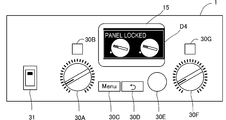
- FIG. 2 is a diagram showing the configuration of the operation panel of the power amplifier 1.
- the operation panel has a rectangular display 15 disposed substantially above the center.
- the operation panel has a power switch 31 disposed on the lower left side.
- the operation panel On the right side of the power switch 31, the operation panel has an Ach level knob 30A for controlling the output level of the Ach sound signal and an Ach selection button 30B labeled “A” arranged vertically.
- the operation panel is arranged side by side with a menu key (Menu) 30C and a return key 30D on the right side of the Ach level knob 30A.
- a rotary encoder with a push switch (hereinafter referred to as “encoder”) 30E is arranged on the right side of the return key 30D.
- the push switch has a function as an enter key.
- the operation panel arranges a Bch level knob 30F for controlling the output level of the Bch sound signal and a Bch selection button 30G labeled “B” vertically in Nara on the right side of the encoder 30E.
- the operation panel may be provided with a power lamp (POWER) and a warning lamp (ALERT) above the power switch 31.
- the Ach protection lamp PL-A and the Bch protection lamp PL-B may be arranged on the operation panel above the Ach selection button 30B and the Bch selection button 30G.
- the power amplifier 1 includes a protection circuit. When the protection circuit detects an abnormality in the output stage of each channel, the CPU 10 lights the corresponding protect lamp PL-A or protect lamp PL-B.
- the display 15 in the figure displays a home screen that is a basic screen.
- the display 15 displays the current output levels of Ach and Bch (Ach is ⁇ 15 dB, Bch is ⁇ 19 dB) on the home screen.
- the locked state of the power amplifier 1 and the procedure for releasing the locked state will be described.
- the user first presses the menu key 30C while the home screen is displayed on the display unit 15 as shown in FIG. 3A.
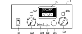
- the CPU 10 displays the menu screen shown in FIG.
- the user can select any one of a plurality of prepared menus.
- the user selects [UTILITY] as illustrated.
- the CPU 10 displays the selected [UTILITY] with black and white reversed.
- the user then pushes encoder 30E. This confirms the selection of [UTILITY].
- the CPU 10 displays the UTILITY screen shown in FIG.
- the user selects one of the prepared utilities.
- the CPU 10 displays the display of [PANEL LOCK] reversed in black and white.
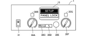
- the CPU 10 displays the PANEL ⁇ LOCK screen shown in FIG.
- the CPU 10 displays the characters “PANEL LOCK OFF” on the display unit 15 as shown.
- the CPU 10 displays the display of [PANEL LOCK OFF] reversed in black and white.
- the CPU 10 displays the window of the dialog D1 shown in FIG. 3E on the front of the PANEL lock screen displayed on the display unit 15.
- the CPU 10 displays [OFF] for unlocking, not shown, and parameter values displayed on the display unit 15 and [ALL] for locking the operation elements provided on the panel. To do.
- the encoder 30E is turned and [ALL] is selected as shown.
- the CPU 10 displays [ALL] with black and white reversed.
- the user then pushes encoder 30E to confirm the selection of [ALL].
- the CPU 10 displays the home screen shown in FIG. 3F on the display unit 15 with the display values of the parameters of the display unit 15 of the power amplifier 1 and all the controls provided on the panel in the locked state.
- the locked state even if the user operates the operator of the panel, the value of the parameter assigned to the operator is not changed, and the display value displayed on the display unit 15 does not change. That is, in the locked state, the setting values according to the position of the operator and the operation amount are not reflected in the parameter setting values in the current memory.
- FIG. 4A to 4G are diagrams showing a part of the panel of the power amplifier 1.
- FIG. 4A to 4G are diagrams showing a part of the panel of the power amplifier 1.
- the CPU 10 displays a dialog shown in FIG. 4A on the front of the home screen displayed on the display unit 15. Open the D2 window. In this case, the user operates the Ach level knob 30A and performs an operation of rotating the Ach level knob 30A to the right.
- the user can select one of maintaining the locked state (PERMANENTLY), unlocking (UNLOCK), and temporarily unlocking (TEMPORARILY) by turning the encoder 30E.
- the selection of unlock (UNLOCK) is confirmed.
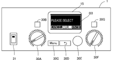
- the CPU 10 displays a window of a dialog D3 shown in FIGS. 4B and 4D on the front surface of the home screen displayed on the display 15.
- the user maintains the locked state by turning the encoder 30E [CANCEL], and the current memory value in the parameter assigned to the operator (the parameter in the current memory when the locked state is set).
- [CUR ...] which is the first method for enabling the operation of the operation element after the value of the operated operation element is returned to the setting value of the operation element), and the setting value of the current operation element.
- [KNOB] which is the second method of reflecting the setting value of the parameter assigned to, can be selected.
- the CPU 10 displays the black and white of [KNOB] reversed.
- the selection of [KNOB] is confirmed.
- the CPU 10 releases the lock state, and rewrites the current memory setting value with the current operation element setting value, thereby updating the current memory value of the parameter assigned to the operation element, and the home shown in FIG. 4C.
- the screen is displayed on the display 15.
- the setting value of the Ach level in the current memory is rewritten to the setting value indicated by the changed Ach level knob 30A, and the digital signal is output with the setting value.
- the processing unit 21 performs signal processing.
- the CPU 10 preferably gradually brings the set value in the current memory closer to the current set value of the Ach level knob 30A.
- the CPU 10 updates the current output level of Ach from ⁇ dB to ⁇ 35 dB (set value indicated by the current Ach level knob 30A) on the home screen.
- the user can adjust the volume of Ach or Bch by rotating the Ach level knob 30A or the Bch level knob 30F.
- the CPU 10 displays the black and white of [CUR ...] reversed.
- the selection of [CUR ...] is confirmed.
- the CPU 10 displays a dialog D4 on the front surface of the home screen displayed on the display 15.
- the CPU 10 displays an image simulating the operators of the Ach level knob 30A and the Bch level knob 30F shown in FIG. 4E.
- the CPU 10 displays a simulated operator imitating the operation position of the operator in the dialog D4.
- the CPU 10 displays the current memory values of the Ach and Bch levels in the current memory with white circles near the simulated operator.
- the current memory value is a set value of the Ach level knob 30A and the Bch level knob 30F at the time when the lock state is established.
- the Ach level knob 30A is operated, but the Bch level knob 30F is not operated. Therefore, the value of the Bch level knob 30F is equal to the current memory value of the Bch level. Therefore, the CPU 10 displays [OK] in the vicinity of the simulated operator of Bch.
- the CPU 10 rotates the simulated operator of Bch to the right as shown in FIG. 4F. Further, since the value of the Bch level knob 30F deviates from the current memory value of the Bch level, the CPU 10 deletes [OK] displayed in the vicinity of the Bch simulated operator.
- the CPU 10 sets the values of the Ach level knob 30A and the Bch level knob 30F to Ach and It is determined that the current memory value of the Bch level is equal to the current memory value, and the lock state is released.
- the CPU 10 displays the home screen shown in FIG. On the home screen, the CPU 10 sets the current output levels of Ach and Bch to ⁇ dB, which is the same as when the lock state is set.
- the user can adjust the volume level of Ach or Bch by rotating the Ach level knob 30A or the Bch level knob 30F.
- the CPU 10 starts the procedure for unlocking the panel lock when the Ach level knob 30A is operated.
- the CPU 10 may also start the unlocking procedure of the panel lock when operating other controls except for the Ach level knob 30A and the Bch level knob 30F.
- the setting values of the controls of the Ach level knob 30A and the Bch level knob 30F are the same as the current memory values on the current memory of the controls. Therefore, when the user selects [CUR...] In the dialog D3 as shown in FIG. 4D, the CPU 10 unlocks without opening the dialog D4 and displays the home screen shown in FIG. 4F.
- the CPU 10 unlocks the current memory value in the current memory without being updated, and displays the home screen shown in FIG. 4C. To do. Further, the CPU 10 does not update the current output levels of Ach and Bch on the home screen.
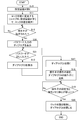
- FIG. 5 is a flowchart of the panel lock process executed by the CPU 10.
- the panel lock process starts when [PANEL LOCK] selection is confirmed on the UTILITY screen shown in FIG. 3B.
- the CPU 10 displays a PANEL lock screen shown in FIG.
- step S11 the CPU 10 shifts to the locked state by performing the procedure shown in FIGS. 3D and 3E.
- the CPU 10 closes the setting screen and displays the home screen shown in FIG. 3F.
- step S12 the CPU 10 determines whether or not the operation element has been operated.
- the CPU 10 determines that the operator is not operated (No)
- the CPU 10 repeatedly performs the process of step S12. If the CPU 10 determines that the operator has been operated (Yes), the CPU 10 proceeds to step S13.
- step S13 the CPU 10 opens a dialog D2 window shown in FIG. 4A.
- the user turns the encoder 30E to select [OK] in the window of the dialog D2 and pushes the encoder 30E, the selection of unlocking (PARMANENTLY) is confirmed.
- CPU10 opens the window of dialog D3 shown to FIG. 4B or FIG. 4D.
- the CPU 10 When the user selects [KNOB], the CPU 10 reflects the setting value of the current operator in the setting value of the current memory, and proceeds to step S15. In this case, the CPU 10 rewrites the setting value of the parameter on the current memory with the setting value of the current operator.
- the digital signal processing unit 21 performs signal processing with the set value.
- step S15 the CPU 10 releases the lock state of the panel lock, closes the window of the dialog D3 for selecting the release method, and displays the home screen shown in FIG. As a result, the panel lock process ends.
- the user can adjust the volume level of Ach or Bch by rotating the Ach level knob 30A or the Bch level knob 30F.
- step S14 the CPU 10 branches to step S17 in order to release the lock state when the setting value of the operator matches the current memory value.
- step S17 the CPU 10 opens a window of a dialog D4 for displaying a simulated operator simulating the position of the operator, imitating the operators of the Ach level knob 30A and the Bch level knob 30F shown in FIG. 4E. Proceed to S18.
- step S18 the CPU 10 sets the simulated operator in the dialog D4 according to the rotation operation content of the Ach level knob 30A or the Bch level knob 30F. To rotate and display.
- step S19 the CPU 10 determines whether or not the current setting value of the Ach level knob 30A and the Bch level knob 30F is equal to the current memory value.
- the CPU 10 repeats the processing of step S18 and step S19 until it determines that the current setting values of the Ach level knob 30A and the Bch level knob 30F are equal to the current memory value. If the CPU 10 determines that the current setting values of the Ach level knob 30A and the Bch level knob 30F are equal to the current memory value, the process proceeds to step S20.
- step S20 the CPU 10 releases the lock state of the panel lock, closes the window of the dialog D3, and displays the home screen shown in FIG. As a result, the panel lock process ends.
- the user can adjust the volume level of Ach or Bch by rotating the Ach level knob 30A or the Bch level knob 30F.
- FIG. 6 is a diagram showing a flowchart of another panel lock process executed by the CPU 10.
- the CPU 10 detects that the operation element has been operated in step S12 (Yes)
- the CPU 10 proceeds to step S30.
- step S30 the CPU 10 displays a dialog for inputting a password, and allows the user to input the password.
- the CPU 10 determines whether or not the input password is correctly input in step S13. If the CPU 10 determines that the correct password has not been input (No), the CPU 10 displays a dialog indicating that the password is incorrect and repeats the process of step S31 until the correct password is input.
- step S31 If the CPU 10 determines in step S31 that the correct password has been input (Yes), the CPU 10 proceeds to step S13. Since the processing from step S13 to step S20 is as described above, the description thereof is omitted.
- the panel lock process shown in FIG. 6 includes steps S30 and S31 for performing a password input process, so that security is increased and only the person in charge can be unlocked.
- FIG. 7 is a view showing a flowchart of still another panel lock process executed by the CPU 10. If the CPU 10 determines in step S31 that a correct password has been input (Yes), the CPU 10 proceeds to step S17.
- step S17 to step S20 Since the processing from step S17 to step S20 is as described above, description thereof is omitted. However, in yet another panel lock process shown in FIG. 7, the processes from step S14 to step S16 are omitted.
- the CPU 10 releases the lock state when the current setting value of the operator matches the current memory value.
- the setting value of the current memory is updated with the current setting value of the operator, the volume level may change abruptly. Therefore, in the panel lock process of FIG. 7, the CPU 10 releases the lock state when the current setting value of the operator matches the current memory value.
- the panel lock processing of FIG. 7 includes steps S30 and S31 for performing password input processing, security is increased and it is possible to prevent anyone other than the person in charge from releasing the lock.
- an example of a 2ch power amplifier is shown.
- the present invention can also be applied to an audio device other than 2ch, for example, an audio device such as 4ch or 8ch.
- the present invention is not limited to the power amplifier.
- the present invention can also be applied to a setting method for an acoustic device other than a power amplifier, for example, a speaker processor or a stage box for extending the input / output of a digital mixer.
- the embodiment has shown a method for unlocking the panel lock.
- the present invention is not limited to the display of the display provided on the panel and the lock of the operation element, but is applied to the unlocking method of the display of the display provided other than the panel and the lock of the operation element. be able to.
- the simulated operation is performed when the setting values of the controls of the Ach level knob 30A and the Bch level knob 30F are different from the current memory value (setting value) on the current memory corresponding to the controls. Since the dialog for displaying the child is opened, it is possible to visually grasp that the value of the operation element is deviated from the set value, and it is easy to understand.
- the lock state is released by operating an operator whose setting value is different from the setting value of the current memory so that the setting value indicated by the operator becomes equal to the setting value of the current memory. Therefore, the user can release the locked state only by operating the operator, and can release the lock quickly and easily.
- a method selection screen for releasing the locked state is displayed.
- the user sets the current memory setting value using the first method that is canceled when the current memory setting value is equal to the setting value of the operation element, and the current operation element setting value. It is possible to select at least one of the second method of updating the lock and releasing the lock. Therefore, the user can perform unlocking according to the usage situation.
Landscapes
- Engineering & Computer Science (AREA)
- Physics & Mathematics (AREA)
- Theoretical Computer Science (AREA)
- Signal Processing (AREA)
- Acoustics & Sound (AREA)
- General Engineering & Computer Science (AREA)
- Computer Security & Cryptography (AREA)
- General Physics & Mathematics (AREA)
- Software Systems (AREA)
- Computer Hardware Design (AREA)
- Health & Medical Sciences (AREA)
- General Health & Medical Sciences (AREA)
- Otolaryngology (AREA)
- Human Computer Interaction (AREA)
- Computer Graphics (AREA)
- Multimedia (AREA)
- User Interface Of Digital Computer (AREA)
- Control Of Amplification And Gain Control (AREA)
Abstract
音響機器は、操作子と、メモリと、処理部と、制御部と、表示部と、を備えている。操作子は、設定値を受け付ける。メモリは、前記設定値を記憶する。処理部は、前記メモリに記憶された前記設定値に応じて処理を行なう。制御部は、前記操作子で受け付けた前記設定値に応じて前記メモリに記憶されている前記設定値を更新する通常状態と、前記操作子で受け付けた前記設定値に関わらず前記メモリの前記設定値を固定するロック状態と、を実行し、前記メモリの前記設定値と前記操作子で受け付ける前記設定値とが同一になった場合に前記ロック状態を解除する第1の方法、または前記操作子で受け付ける前記設定値で前記メモリに記憶されている前記設定値を更新して前記ロック状態を解除する第2の方法、のいずれかにより前記ロック状態を解除して前記通常状態に移行する。表示部は、前記第1の方法または前記第2の方法の選択を受け付けるための選択画面を表示する。
Description
この発明の一実施形態は、音響機器、ロック解除方法、プログラム、および媒体に関する。
従来のパワーアンプは、アッテネータの操作子を含む複数の操作子と、パネルと、を備えている。前記パネルは、前記複数の操作子を配置する。パワーアンプは、設置時に、設置場所および使用環境に好適な設定を行なう。
設定が行われた後において、担当者以外の者が、パネルの操作子を操作すると、好適な設定が変更されて支障が発生する恐れがある。
そこで、従来のパワーアンプは、担当者以外の者が操作子を操作できないように、パネルの前面を覆うカバーを備えている。また、従来のデジタルパワーアンプは、パネルの操作を行なっても設定に反映されないロック状態を実行する、パネルロック機能を備えている(非特許文献1参照)。
前記複数の操作子は、音量レベルを調整するための操作子を含む。デジタルパワーアンプは、操作子の位置に応じて、音量レベルを変更する。デジタルパワーアンプは、ロック状態では、操作子の位置を変更しても音量レベルを変更しない。デジタルパワーアンプは、ロック状態を解除した時、操作子の位置が変更されていると、変更後の操作子の位置に応じて、音量を変更する。
ヤマハ株式会社 POWER AMPLIFIER TX6n/TX5n/TX4n リファレンスマニュアル[online], [平成28年 2月21日検索],インターネット<http://download.yamaha.com/api/asset/file?language=ja&site=countrysite-master.prod.exp.yamaha.com&asset_id=48589>
ユーザは、使用状況に応じて、操作子の位置を元に戻してからロック状態を解除したい場合がある。また、ユーザは、使用状況に応じて、
そこで、本発明の一実施形態は、利用者が使用状況に応じてロック状態の解除を行うことができる、あるいは、利用者が操作子の位置が変更されていることを容易に認識することができる、音響機器、ロック解除方法、プログラム、および媒体を提供することを目的としている。
そこで、本発明の一実施形態は、利用者が使用状況に応じてロック状態の解除を行うことができる、あるいは、利用者が操作子の位置が変更されていることを容易に認識することができる、音響機器、ロック解除方法、プログラム、および媒体を提供することを目的としている。
上記目的を達成するために、本発明の一実施形態の音響機器は、操作子と、メモリと、処理部と、制御部と、表示部と、を備えている。操作子は、設定値を受け付ける。メモリは、前記設定値を記憶する。処理部は、前記メモリに記憶された前記設定値に応じて処理を行なう。制御部は、前記操作子で受け付けた前記設定値に応じて前記メモリに記憶されている前記設定値を更新する通常状態と、前記操作子で受け付けた前記設定値に関わらず前記メモリの前記設定値を固定するロック状態と、を実行し、前記メモリの前記設定値と前記操作子で受け付ける前記設定値とが同一になった場合に前記ロック状態を解除する第1の方法、または前記操作子で受け付ける前記設定値で前記メモリに記憶されている前記設定値を更新して前記ロック状態を解除する第2の方法、のいずれかにより前記ロック状態を解除して前記通常状態に移行する。表示部は、前記第1の方法または前記第2の方法の選択を受け付けるための選択画面を表示する。
または、制御部は、前記操作子で受け付けた前記設定値に応じて前記メモリに記憶されている前記設定値を更新する通常状態と、前記操作子で受け付けた前記設定値に関わらず前記メモリの前記設定値を固定するロック状態と、を実行する。表示部は、前記ロック状態を解除して前記通常状態に移行する際に、前記メモリの前記設定値と前記操作子で受け付ける前記設定値と、が異なる場合は、その旨を示す表示画面を表示する。
本発明の一実施形態によれば、利用者が使用状況に応じてロック状態の解除を行うことができる、あるいは、利用者が操作子の位置が変更されていることを容易に認識することができる。
図1は、パワーアンプ1の構成を示す機能ブロック図である。
パワーアンプ1は、AchおよびBchの2chを有する。パワーアンプ1は、CPU(Central Processing Unit)10、フラッシュメモリ11、RAM(Random Access Memory)12、その他I/O13、操作子14、表示器15、波形入力部20、デジタル信号処理部21、D/A・A/D部22、およびアナログ電力増幅部23を備える。各構成は、バス24を介して接続している。デジタル信号処理部21は、DSP(Digital Signal Processor)で構成する。
パワーアンプ1は、AchおよびBchの2chを有する。パワーアンプ1は、CPU(Central Processing Unit)10、フラッシュメモリ11、RAM(Random Access Memory)12、その他I/O13、操作子14、表示器15、波形入力部20、デジタル信号処理部21、D/A・A/D部22、およびアナログ電力増幅部23を備える。各構成は、バス24を介して接続している。デジタル信号処理部21は、DSP(Digital Signal Processor)で構成する。
CPU10は、パワーアンプ1の動作を統括制御する制御部である。CPU10は、媒体であるフラッシュメモリ11に記憶された制御プログラムを実行することにより、操作子14の操作に従ったパラメータの編集、表示器15における表示の制御、またはパネルロックのロック状態/ロック解除の制御等の処理を行う。
フラッシュメモリ11は、CPU10が実行する制御プログラム、コンフィグデータおよびスピーカに対応するSPプリセット、等を記憶する書き換え可能な不揮発性記憶媒体である。なお、コンフィグデータは、入力部から出力部までの音信号の経路と、その経路における信号処理とを規定する。
RAM12は、CPU10が各種のデータを書き込み及び読み出しするための揮発性記憶手段である。RAM12は、CPU10のワークメモリ、またはデジタル信号処理部21に現在設定されている設定値である現在メモリ値を記憶するカレントメモリとなる。
その他I/O13は、種々の外部機器を接続して通信を行うためのインタフェースである。その他I/O13における通信に用いる規格は、イーサネット(登録商標)、またはUSB(Universal Serial Bus)等、任意のものが採用される。通信は、有線であっても無線であってもよい。
表示器15は、CPU10の制御に従って種々の情報を表示する表示部である。表示器15は、例えば液晶パネル(LCD)または発光ダイオード(LED)である。
次に、音信号の入力部から出力部までの経路の構成について説明する。波形入力部20は、外部ソース2からアナログのAchとBchの音信号を受け取る。波形入力部20は、Achの音信号およびBchの音信号を、それぞれ、デジタルの音信号に変換してデジタル信号処理部21へ供給する。
デジタル信号処理部21は、Achの音信号およびBchの音信号に対して、クロスオーバー処理、ディレイ処理、イコライザ処理、リミッタ処理、またはダイナミクス処理などの信号処理を施す。デジタル信号処理部21は、処理済みのAchの音信号およびBchの音信号を、D/A・A/D部22へ出力する。
D/A・A/D部22は、デジタルのAchの音信号およびBchの音信号をアナログのAchの音信号およびBchの音信号に変換し、アナログ電力増幅部23に供給する。
アナログ電力増幅部23は、アナログのAchの音信号およびBchの音信号を増幅し、増幅されたAchの音信号およびBchの音信号を、スピーカ端子を介して外部のスピーカ3へ出力する。
図2は、パワーアンプ1の操作パネルの構成を示す図である。図2に示すように、操作パネルは、ほぼ中央の上側に、矩形状の表示器15を配置する。また、操作パネルは、左側の下部に電源スイッチ31を配置する。操作パネルは、電源スイッチ31の右側に、Achの音信号の出力レベルを制御するAchレベルつまみ30Aと、「A」と表記されたAch選択ボタン30Bと、を縦に並んで配置する。操作パネルは、Achレベルつまみ30Aの右側に、メニューキー(Menu)30Cと、リターンキー30Dと、横に並んで配置する。
さらに、操作パネルは、リターンキー30Dの右側に、プッシュスイッチ付きのロータリーエンコーダー(以下、「エンコーダー」という)30Eを配置する。プッシュスイッチは、エンターキーとしての機能を有している。
操作パネルは、エンコーダー30Eの右側にBchの音信号の出力レベルを制御するBchレベルつまみ30Fと、「B」と表記されたBch選択ボタン30Gと、を縦に奈良で配置する。また、操作パネルは、電源スイッチ31の上側に電源ランプ(POWER)と警告ランプ(ALERT)とを配置してもよい。また、操作パネルは、Achの選択ボタン30B、およびBchの選択ボタン30Gの上側に、AchのプロテクトランプPL-A、およびBchのプロテクトランプPL-Bを配置してもよい。パワーアンプ1は、保護回路を備えている。CPU10は、該保護回路で各chの出力段の異常を検出した時に、対応するプロテクトランプPL-AまたはプロテクトランプPL-Bを点灯する。
なお、利用者がAchレベルつまみ30AまたはBchレベルつまみ30Fを操作すると、CPU10は、操作量に応じてAchまたはBchの出力レベルを制御する。図中の表示器15は、基本画面であるホーム画面を表示している。表示器15は、ホーム画面では、AchおよびBchの現在の出力レベル(Achが-15dB、Bchが-19dB)を表示する。
次に、パワーアンプ1のロック状態、およびロック状態を解除する手順を説明する。パネルロックのロック状態/ロック解除を設定するためには、ユーザは、まず、図3Aに示すように、表示器15にホーム画面が表示されている状態において、メニューキー(Menu)30Cを押す。これにより、CPU10は、図3Bに示すメニュー画面を表示器15に表示する。このメニュー画面では、ユーザは、用意された複数のメニューのいずれか1つを選択することができる。ここでは、ユーザは、図示するように[UTILITY]を選択する。この場合、CPU10は、選択された[UTILITY]の白黒を反転した表示とする。次いで、ユーザは、エンコーダー30Eをプッシュする。これにより、[UTILITY]の選択が確定する。CPU10は、図3Cに示すUTILITY画面を表示器15に表示する。
UTILITY画面では、ユーザは、用意されている複数のユーティリティのいずれか1つを選択する。ユーザは、図示するように[PANEL LOCK]を選択すると、CPU10は、[PANEL LOCK]の白黒を反転した表示とする。次いで、ユーザが、エンコーダー30Eをプッシュすると、[PANEL LOCK]の選択が確定される。これにより、CPU10は、図3Dに示すPANEL LOCK画面を表示器15に表示する。
PANEL LOCK画面では、CPU10は、図示するように表示器15に[PANEL LOCK OFF]の文字を表示する。ここで、ユーザが図示するように[PANEL LOCK OFF]を選択すると、CPU10は、[PANEL LOCK OFF]の白黒を反転した表示とする。次いで、ユーザがエンコーダー30Eをプッシュすると、CPU10は、表示器15に表示されたPANEL LOCK画面の前面に、図3Eに示すダイアログD1のウィンドウを表示する。
ダイアログD1のウィンドウでは、CPU10は、図示しない、ロック解除するための[OFF]と、表示器15に表示されるパラメータ値およびパネルに設けられた操作子をロック状態とする[ALL]とを表示する。
ユーザは、ロック状態にしたい場合は、エンコーダー30Eを回して、図示するように[ALL]を選択する。CPU10は、[ALL]の白黒を反転した表示とする。次いで、ユーザはエンコーダー30Eをプッシュして[ALL]の選択を確定させる。これにより、CPU10は、パワーアンプ1の表示器15のパラメータの表示値およびパネルに設けられている全ての操作子をロック状態として、図3Fに示すホーム画面を表示器15に表示する。
ロック状態では、ユーザがパネルの操作子を操作しても、当該操作子に割り当てられているパラメータの値は変更されず、表示器15に表示されている表示値も変化しない。すなわち、ロック状態では、カレントメモリ上のパラメータの設定値には、操作子の位置および操作量に応じた設定値が反映されないことになる。
次に、ロック解除の手順を説明する。図4A~図4Gは、パワーアンプ1のパネルの一部を示す図である。
ユーザが、パワーアンプ1のパネルに設けられている複数の操作子のうちいずれか1つの操作子を操作すると、CPU10は、表示器15に表示されたホーム画面の前面に、図4Aに示すダイアログD2のウィンドウを開く。この場合、利用者は、Achレベルつまみ30Aを操作して、Achレベルつまみ30Aを右回転した操作を行なっている。
ダイアログD2のウィンドウでは、ユーザは、エンコーダー30Eを回すことによりロック状態を維持(PERMANENTLY)、ロック解除(UNLOCK)、一時ロック解除(TEMPORARILY)の何れかを選択することができる。ここで、ユーザが[CANCEL]を選択してエンコーダー30Eをプッシュすると、ロック解除(UNLOCK)の選択が確定する。CPU10は、表示器15に表示されたホーム画面の前面に、図4Bおよび図4Dに示すダイアログD3のウィンドウを表示する。ダイアログD3のウィンドウでは、ユーザは、エンコーダー30Eを回すことによりロック状態を維持する[CANCEL]と、操作子に割り当てられたパラメータにおける現在メモリ値(ロック状態にされた時のカレントメモリ上の当該パラメータの設定値)に、操作された操作子の値が戻ってから操作子の操作を有効にする第1の方法である、[CUR…]と、現在の操作子の設定値を、当該操作子に割り当てられたパラメータの設定値に反映させる第2の方法である、[KNOB]と、のいずれかを選択することができる。
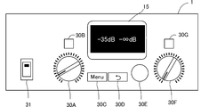
ここで、ユーザがエンコーダー30Eを回して図4Bに示すようにダイアログD3で[KNOB]を選択すると、CPU10は、[KNOB]の白黒を反転した表示とする。次いで、ユーザがエンコーダー30Eをプッシュすると[KNOB]の選択が確定する。CPU10は、ロック状態を解除し、現在の操作子の設定値でカレントメモリの設定値を書き替えることにより、当該操作子に割り当てられたパラメータの現在メモリ値を更新して、図4Cに示すホーム画面を表示器15に表示する。
この場合、Achレベルつまみ30Aの位置が変更されていることから、変更後のAchレベルつまみ30Aが示す設定値に、カレントメモリにおけるAchのレベルの設定値が書き替えられ、当該設定値でデジタル信号処理部21が信号処理を行う。なお、信号処理を行う際には、CPU10は、カレントメモリにおける設定値を、徐々に現在のAchレベルつまみ30Aの設定値に近づけていくことが好ましい。
また、CPU10は、ホーム画面において、Achの現在の出力レベルを-∞dBから-35dB(現在のAchレベルつまみ30Aが示す設定値)の表示に更新する。なお、ロック解除されると、ユーザは、Achレベルつまみ30AまたはBchレベルつまみ30Fを回転操作することで、AchまたはBchの音量を調整することができる。
図4Dに示すように、ユーザがエンコーダー30Eを回して、ダイアログD3で[CUR…]を選択すると、CPU10は、[CUR…]の白黒を反転した表示とする。次いで、ユーザがエンコーダー30Eをプッシュすると[CUR…]の選択が確定する。CPU10は、表示器15に表示されたホーム画面の前面に、ダイアログD4を表示する。CPU10は、ダイアログD4において、図4Eに示すAchレベルつまみ30AおよびBchレベルつまみ30Fの操作子を模した画像を表示する。また、CPU10は、ダイアログD4において、操作子の操作位置を模した模擬操作子を表示する。
CPU10は、ダイアログD4において、カレントメモリにおけるAchおよびBchのレベルの現在メモリ値を、模擬操作子の近傍に白丸で表示する。現在メモリ値は、ロック状態にされた時点におけるAchレベルつまみ30AおよびBchレベルつまみ30Fの設定値となる。
この例では、Achレベルつまみ30Aは操作されたが、Bchレベルつまみ30Fは操作されていないため、Bchレベルつまみ30Fの値と、Bchのレベルの現在メモリ値とは等しい。したがって、CPU10は、Bchの模擬操作子の近傍に、[OK]の表示をする。
ここで、ユーザがBchレベルつまみ30Fを右回転する操作を行うと、CPU10は、図4Fに示すように、Bchの模擬操作子を右回転させる。また、CPU10は、Bchレベルつまみ30Fの値が、Bchのレベルの現在メモリ値からずれるので、Bchの模擬操作子の近傍に表示した[OK]を消去する。
また、ユーザがAchレベルつまみ30AおよびBchレベルつまみ30Fを回転操作して、AchおよびBchの模擬操作子が白丸に合うと、CPU10は、Achレベルつまみ30AおよびBchレベルつまみ30Fの値が、AchおよびBchのレベルの現在メモリ値に等しくなったと判断して、ロック状態を解除する。CPU10は、図4Gに示すホーム画面を表示器15に表示する。CPU10は、ホーム画面において、AchとBchの現在の出力レベルを、ロック状態にされた時点と同じ-∞dBにする。ロック解除されると、ユーザは、Achレベルつまみ30AまたはBchレベルつまみ30Fを回転操作することで、AchまたはBchの音量のレベルを調整することができる。
以上の説明では、CPU10は、Achレベルつまみ30Aが操作された場合に、パネルロックのロック解除の手順を開始する。しかし、例えば、CPU10は、Achレベルつまみ30AおよびBchレベルつまみ30Fを除く他の操作子を操作した時にも、パネルロックのロック解除の手順を開始してもよい。この場合、Achレベルつまみ30AおよびBchレベルつまみ30Fの操作子の設定値が、当該操作子のカレントメモリ上の現在メモリ値と一致していることになる。したがって、ユーザが図4Dに示すようにダイアログD3で[CUR…]を選択した場合、CPU10は、ダイアログD4を開くことなくロック解除して、図4Fに示すホーム画面を表示する。また、ユーザが図4Bに示すようにダイアログD3で[KNOB]を選択した場合、CPU10は、カレントメモリ上の現在メモリ値を更新されることなくロック解除して、図4Cに示すホーム画面を表示する。さらに、CPU10は、ホーム画面におけるAchとBchの現在の出力レベルも更新しない。
次に、図5は、CPU10が実行するパネルロック処理のフローチャートである。パネルロック処理は、図3Bに示すUTILITY画面で[PANEL LOCK]の選択が確定された時にスタートする。CPU10は、ステップS10において、図3Dに示すPANEL LOCK画面を表示器15に表示する。次いで、CPU10は、ステップS11において、図3Dおよび図3Eに示す手順を行うことにより、ロック状態に移行する。CPU10は、設定画面を閉じて、図3Fに示すホーム画面を表示する。
次いで、CPU10は、ステップS12において、操作子が操作されたか否かを判断する。CPU10は、操作子が操作されていないと判断した場合(No)、ステップS12の処理を繰り返し行う。CPU10は、操作子が操作されたと判断した場合(Yes)、ステップS13に進む。ステップS13では、CPU10は、図4Aに示すダイアログD2のウィンドウを開く。ユーザは、ダイアログD2のウィンドウにおいて、エンコーダー30Eを回して[OK]を選択し、エンコーダー30Eをプッシュすると、ロック解除(PARMANENTLY)の選択が確定する。CPU10は、図4Bまたは図4Dに示すダイアログD3のウィンドウを開く。
ユーザは、ダイアログD3のウィンドウにおいて、[CANCEL]、[CUR…]、または[KNOB]のいずれかを使用状況に応じて選択する。ユーザが[CANCEL]を選択すると、CPU10は、ステップS12に戻り、ロック状態を維持する。
ユーザが[KNOB]を選択すると、CPU10は、現在の操作子の設定値をカレントメモリの設定値に反映し、ステップS15に進む。この場合、CPU10は、カレントメモリ上の当該パラメータの設定値を現在の操作子の設定値で書き替える。デジタル信号処理部21は、当該設定値で信号処理を行う。
ステップS15で、CPU10は、パネルロックのロック状態を解除し、解除方法を選択するダイアログD3のウィンドウを閉じ、図4Cに示すホーム画面を表示器15に表示する。これにより、パネルロック処理は終了する。この場合、ロック解除されているため、ユーザは、Achレベルつまみ30AまたはBchレベルつまみ30Fを回転操作することで、AchまたはBchの音量レベルを調整することができる。
さらに、ステップS14において、ユーザが[CUR…]を選択すると、CPU10は、操作子の設定値が、現在メモリ値と一致した時にロック状態を解除するために、ステップS17に分岐する。ステップS17で、CPU10は、図4Eに示すAchレベルつまみ30AおよびBchレベルつまみ30Fの操作子を模し、操作子の位置を模した模擬操作子を表示するためのダイアログD4のウィンドウを開き、ステップS18に進む。
ここで、ユーザがAchレベルつまみ30AまたはBchレベルつまみ30Fを回転操作すると、ステップS18にて、CPU10は、ダイアログD4における模擬操作子を、Achレベルつまみ30AまたはBchレベルつまみ30Fの回転操作内容に応じて回転して表示する。
次いで、ステップS19にて、CPU10は、Achレベルつまみ30AおよびBchレベルつまみ30Fの、現在の設定値と、現在メモリ値とが等しいか否かを判断する。CPU10は、Achレベルつまみ30AおよびBchレベルつまみ30Fの現在の設定値と、現在メモリ値とが等しいと判断するまで、ステップS18およびステップS19の処理をが繰り返し行う。CPU10は、Achレベルつまみ30AおよびBchレベルつまみ30Fの現在の設定値と、現在メモリ値とが等しいと判断すると、ステップS20に進む。
ステップS20で、CPU10は、パネルロックのロック状態を解除し、ダイアログD3のウィンドウを閉じて図4Gに示すホーム画面を表示器15に表示する。これにより、パネルロック処理は終了する。この場合、ロック解除されているため、ユーザは、Achレベルつまみ30AまたはBchレベルつまみ30Fを回転操作することで、AchまたはBchの音量レベルを調整することができる。
次に、図6は、CPU10が実行する他のパネルロック処理のフローチャートを示す図である。CPU10は、ステップS12において、操作子が操作されたことを検出すると(Yes)、ステップS30に進む。
ステップS30で、CPU10は、パスワードを入力するためのダイアログを表示し、ユーザにパスワードを入力させる。CPU10は、ユーザがパスワードを入力すると、ステップS13において、入力されたパスワードが正しく入力されたか否かを判断する。ここで、CPU10は、正しいパスワードが入力されていないと判断(No)した場合は、パスワードが正しくない旨のダイアログを表示して、正しいパスワードが入力されるまでステップS31の処理を繰り返し行う。
CPU10は、ステップS31で、正しいパスワードが入力されたと判断(Yes)した場合、ステップS13に進む。ステップS13からステップS20までの処理は上記した通りであるので、その説明は省略する。
図6に示すパネルロック処理は、パスワード入力処理を行うステップS30およびステップS31を備えていることから、セキュリティが高くなり、担当者以外がロック解除できないようにすることができる。
次に、図7は、CPU10が実行するさらに他のパネルロック処理のフローチャートを示す図である。CPU10は、ステップS31で、正しいパスワードが入力されたと判断(Yes)した場合は、ステップS17に進む。
ステップS17からステップS20までの処理は上記した通りであるので、その説明は省略する。ただし、図7に示すさらに他のパネルロック処理では、ステップS14からステップS16の処理が省略されている。CPU10は、操作子の現在の設定値と、現在メモリ値と、が一致した時にロック状態を解除する。現在の操作子の設定値で、カレントメモリの設定値が更新されると、急激に音量レベルが変化するおそれがある。そのため、図7のパネルロック処理では、CPU10は、操作子の現在の設定値と、現在メモリ値と、が一致した時にロック状態を解除する。また、図7のパネルロック処理では、パスワード入力処理を行うステップS30およびステップS31を備えていることから、セキュリティが高くなり、担当者以外がロック解除できないようにすることができる。
以上の実施形態は、2chのパワーアンプの例を示した。しかし、本発明は、2ch以外の音響機器、例えば、4ch、または8ch等の音響機器にも適用できる。また、本発明は、パワーアンプに限るものではない。本発明は、パワーアンプ以外の音響機器、例えば、スピーカプロセッサ、またはデジタルミキサの入出力を拡張するステージボックスなどの設定方法にも適用できる。また、実施形態は、パネルロックのロック解除方法を示した。しかし、本発明は、パネルに設けられている表示器の表示や操作子のロックに限るものではなく、パネル以外に設けられている表示器の表示や操作子のロックのロック解除方法に適用することができる。
また、上記実施形態は、Achレベルつまみ30AおよびBchレベルつまみ30Fの操作子の設定値が、当該操作子に対応するカレントメモリ上の現在メモリ値(設定値)とずれている場合に、模擬操作子を表示するダイアログを開くため、操作子の値が設定値とずれていることが視覚的に把握でき、理解し易くなる。この場合、カレントメモリの設定値と、設定値がずれている操作子を操作して、当該操作子の示す設定値を、カレントメモリの設定値に等しくすると、ロック状態が解除される。したがって、ユーザは、操作子の操作だけでロック状態を解除することができ、迅速かつ簡易にロック解除することができる。また、上記実施形態は、ロック状態において、複数の操作子のいずれかが1つの操作子が操作されると、ロック状態を解除するための方法選択画面を表示する。ユーザは、該方法選択画面において、カレントメモリの設定値と、操作子の設定値とが等しくなった場合に解除する第1の方法と、現在の操作子の設定値で、カレントメモリの設定値を更新してロック解除する第2の方法と、少なくともいずれか1つを選択することができる。したがって、ユーザは、使用状況に応じたロック解除を行うことができる。
最後に、本実施形態の説明は、すべての点で例示であって、制限的なものではないと考えられるべきである。本発明の範囲は、上述の実施形態ではなく、特許請求の範囲によって示される。さらに、本発明の範囲には、特許請求の範囲と均等の意味および範囲内でのすべての変更が含まれることが意図される。
1…パワーアンプ、2…外部ソース、3…スピーカ、10…CPU、11…フラッシュメモリ、12…RAM、13…その他I/O、14…操作子、15…表示器、20…波形入力部、21…デジタル信号処理部、22…D/A・A/D部、23…アナログ電力増幅部、24…バス、30A…Achレベルつまみ、30B…Bch選択ボタン、30C…メニューキー、30D…リターンキー、30E…ロータリーエンコーダー、30F…Bchレベルつまみ、30G…Bch選択ボタン、31…電源スイッチ
Claims (13)
- 設定値を受け付ける操作子と、
前記設定値を記憶するメモリと、
前記メモリに記憶された前記設定値に応じて処理を行なう処理部と、
前記操作子で受け付けた前記設定値に応じて前記メモリに記憶されている前記設定値を更新する通常状態と、前記操作子で受け付けた前記設定値に関わらず前記メモリの前記設定値を固定するロック状態と、を実行し、前記メモリの前記設定値と前記操作子で受け付ける前記設定値とが同一になった場合に前記ロック状態を解除する第1の方法、または前記操作子で受け付ける前記設定値で前記メモリに記憶されている前記設定値を更新して前記ロック状態を解除する第2の方法、のいずれかにより前記ロック状態を解除して前記通常状態に移行する、制御部と、
前記第1の方法または前記第2の方法の選択を受け付けるための選択画面を表示する表示部と、
を備えた音響機器。 - 前記制御部は、前記第2の方法では、前記メモリの前記設定値を、前記メモリに現在記憶されている前記設定値から、前記操作子で受け付けている現在の前記設定値に、徐々に近づける、
請求項1に記載の音響機器。 - 設定値を受け付ける操作子と、
前記設定値を記憶するメモリと、
前記メモリに記憶された前記設定値に応じて処理を行なう処理部と、
前記操作子で受け付けた前記設定値に応じて前記メモリに記憶されている前記設定値を更新する通常状態と、前記操作子で受け付けた前記設定値に関わらず前記メモリの前記設定値を固定するロック状態と、を実行する、制御部と、
前記ロック状態を解除して前記通常状態に移行する際に、前記メモリの前記設定値と前記操作子で受け付ける前記設定値と、が異なる場合は、その旨を示す表示画面を表示する表示部と、
を備えた音響機器。 - 前記ロック状態における前記設定値は、前記ロック状態に設定された時における前記操作子の設定値である、請求項3に記載の音響機器。
- 前記制御部は、前記表示画面が表示されている時に、前記操作子の設定値が前記メモリの設定値と一致した場合に、前記ロック状態を解除する、請求項4に記載の音響機器。
- 前記操作子は、物理操作子であり、
前記制御部は、前記ロック状態において前記操作子が操作された場合、当該操作子の操作状態を模した模擬操作子を前記表示部に表示する、
請求項1乃至請求項5のいずれかに記載の音響機器。 - 複数の前記操作子を備える、請求項1乃至請求項6のいずれかに記載の音響機器。
- 設定値を受け付け、
前記設定値をメモリに記憶し、
前記メモリに記憶された前記設定値に応じて処理を行い、
受け付けた前記設定値に応じて前記メモリに記憶されている前記設定値を更新する通常状態と、前記操作子で受け付けた前記設定値に関わらず前記メモリの前記設定値を固定するロック状態と、を実行し、
前記メモリの前記設定値と前記操作子で受け付ける前記設定値とが同一になった場合に前記ロック状態を解除する第1の方法、または前記操作子で受け付ける前記設定値で前記メモリに記憶されている前記設定値を更新して前記ロック状態を解除する第2の方法、のいずれかの選択を受け付けるための選択画面を表示し、
前記第1の方法または前記第2の方法、のいずれかにより前記ロック状態を解除して前記通常状態に移行する、
ロック解除方法。 - 設定値を受け付け、
前記設定値をメモリに記憶し、
前記メモリに記憶された前記設定値に応じて処理を行い、
受け付けた前記設定値に応じて前記メモリに記憶されている前記設定値を更新する通常状態と、前記操作子で受け付けた前記設定値に関わらず前記メモリの前記設定値を固定するロック状態と、を実行し、
前記ロック状態を解除して前記通常状態に移行する際に、前記メモリの前記設定値と前記操作子で受け付ける前記設定値と、が異なる場合は、その旨を示す表示画面を表示する、
ロック解除方法。 - 設定値を受け付け、
前記設定値をメモリに記憶し、
前記メモリに記憶された前記設定値に応じて処理を行い、
受け付けた前記設定値に応じて前記メモリに記憶されている前記設定値を更新する通常状態と、前記操作子で受け付けた前記設定値に関わらず前記メモリの前記設定値を固定するロック状態と、を実行し、
前記メモリの前記設定値と前記操作子で受け付ける前記設定値とが同一になった場合に前記ロック状態を解除する第1の方法、または前記操作子で受け付ける前記設定値で前記メモリに記憶されている前記設定値を更新して前記ロック状態を解除する第2の方法、のいずれかの選択を受け付けるための選択画面を表示し、
前記第1の方法または前記第2の方法、のいずれかにより前記ロック状態を解除して前記通常状態に移行する、
処理を音響機器に実行させるプログラム。 - 設定値を受け付け、
前記設定値をメモリに記憶し、
前記メモリに記憶された前記設定値に応じて処理を行い、
受け付けた前記設定値に応じて前記メモリに記憶されている前記設定値を更新する通常状態と、前記操作子で受け付けた前記設定値に関わらず前記メモリの前記設定値を固定するロック状態と、を実行し、
前記ロック状態を解除して前記通常状態に移行する際に、前記メモリの前記設定値と前記操作子で受け付ける前記設定値と、が異なる場合は、その旨を示す表示画面を表示する、
処理を音響機器に実行させるプログラム。 - 設定値を受け付け、
前記設定値をメモリに記憶し、
前記メモリに記憶された前記設定値に応じて処理を行い、
受け付けた前記設定値に応じて前記メモリに記憶されている前記設定値を更新する通常状態と、前記操作子で受け付けた前記設定値に関わらず前記メモリの前記設定値を固定するロック状態と、を実行し、
前記メモリの前記設定値と前記操作子で受け付ける前記設定値とが同一になった場合に前記ロック状態を解除する第1の方法、または前記操作子で受け付ける前記設定値で前記メモリに記憶されている前記設定値を更新して前記ロック状態を解除する第2の方法、のいずれかの選択を受け付けるための選択画面を表示し、
前記第1の方法または前記第2の方法、のいずれかにより前記ロック状態を解除して前記通常状態に移行する、
処理を音響機器に実行させるプログラムを記憶した媒体。 - 設定値を受け付け、
前記設定値をメモリに記憶し、
前記メモリに記憶された前記設定値に応じて処理を行い、
受け付けた前記設定値に応じて前記メモリに記憶されている前記設定値を更新する通常状態と、前記操作子で受け付けた前記設定値に関わらず前記メモリの前記設定値を固定するロック状態と、を実行し、
前記ロック状態を解除して前記通常状態に移行する際に、前記メモリの前記設定値と前記操作子で受け付ける前記設定値と、が異なる場合は、その旨を示す表示画面を表示する、
処理を音響機器に実行させるプログラムを記憶した媒体。
Priority Applications (2)
| Application Number | Priority Date | Filing Date | Title |
|---|---|---|---|
| CN201780016847.0A CN108781328B (zh) | 2016-03-17 | 2017-03-14 | 音响设备、锁定解除方法、以及介质 |
| US16/124,925 US10412496B2 (en) | 2016-03-17 | 2018-09-07 | Sound equipment, lock release method, and medium |
Applications Claiming Priority (4)
| Application Number | Priority Date | Filing Date | Title |
|---|---|---|---|
| JP2016053458A JP6690334B2 (ja) | 2016-03-17 | 2016-03-17 | ロック解除方法 |
| JP2016-053458 | 2016-03-17 | ||
| JP2016-053459 | 2016-03-17 | ||
| JP2016053459A JP6763161B2 (ja) | 2016-03-17 | 2016-03-17 | ロック解除方法 |
Related Child Applications (1)
| Application Number | Title | Priority Date | Filing Date |
|---|---|---|---|
| US16/124,925 Continuation US10412496B2 (en) | 2016-03-17 | 2018-09-07 | Sound equipment, lock release method, and medium |
Publications (1)
| Publication Number | Publication Date |
|---|---|
| WO2017159644A1 true WO2017159644A1 (ja) | 2017-09-21 |
Family
ID=59850407
Family Applications (1)
| Application Number | Title | Priority Date | Filing Date |
|---|---|---|---|
| PCT/JP2017/010067 Ceased WO2017159644A1 (ja) | 2016-03-17 | 2017-03-14 | 音響機器、ロック解除方法、プログラム、および媒体 |
Country Status (3)
| Country | Link |
|---|---|
| US (1) | US10412496B2 (ja) |
| CN (1) | CN108781328B (ja) |
| WO (1) | WO2017159644A1 (ja) |
Citations (6)
| Publication number | Priority date | Publication date | Assignee | Title |
|---|---|---|---|---|
| JP2001078300A (ja) * | 1999-09-01 | 2001-03-23 | Yamaha Corp | ディジタルミキサー装置 |
| JP2004252016A (ja) * | 2003-02-19 | 2004-09-09 | Yamaha Corp | パラメータ表示部の制御装置及びプログラム |
| WO2008117337A1 (ja) * | 2007-03-27 | 2008-10-02 | Pioneer Corporation | レベル調節装置、av処理装置およびプログラム |
| JP2010232855A (ja) * | 2009-03-26 | 2010-10-14 | Yamaha Corp | 音響装置 |
| JP2012054857A (ja) * | 2010-09-03 | 2012-03-15 | Sony Corp | 制御端末装置、制御方法 |
| JP2013150267A (ja) * | 2012-01-23 | 2013-08-01 | Yamaha Corp | 制御装置 |
Family Cites Families (4)
| Publication number | Priority date | Publication date | Assignee | Title |
|---|---|---|---|---|
| JP3931028B2 (ja) * | 2000-10-12 | 2007-06-13 | 株式会社ケンウッド | オーディオシステム及び音量調節方法 |
| JP4501746B2 (ja) * | 2005-03-25 | 2010-07-14 | ヤマハ株式会社 | ミキサ装置及びそのコンピュータプログラム |
| US20100179674A1 (en) * | 2009-01-15 | 2010-07-15 | Open Labs | Universal music production system with multiple modes of operation |
| CN201440728U (zh) * | 2009-09-14 | 2010-04-21 | 杨辉隆 | 一种扩音器 |
-
2017
- 2017-03-14 WO PCT/JP2017/010067 patent/WO2017159644A1/ja not_active Ceased
- 2017-03-14 CN CN201780016847.0A patent/CN108781328B/zh not_active Expired - Fee Related
-
2018
- 2018-09-07 US US16/124,925 patent/US10412496B2/en not_active Expired - Fee Related
Patent Citations (6)
| Publication number | Priority date | Publication date | Assignee | Title |
|---|---|---|---|---|
| JP2001078300A (ja) * | 1999-09-01 | 2001-03-23 | Yamaha Corp | ディジタルミキサー装置 |
| JP2004252016A (ja) * | 2003-02-19 | 2004-09-09 | Yamaha Corp | パラメータ表示部の制御装置及びプログラム |
| WO2008117337A1 (ja) * | 2007-03-27 | 2008-10-02 | Pioneer Corporation | レベル調節装置、av処理装置およびプログラム |
| JP2010232855A (ja) * | 2009-03-26 | 2010-10-14 | Yamaha Corp | 音響装置 |
| JP2012054857A (ja) * | 2010-09-03 | 2012-03-15 | Sony Corp | 制御端末装置、制御方法 |
| JP2013150267A (ja) * | 2012-01-23 | 2013-08-01 | Yamaha Corp | 制御装置 |
Also Published As
| Publication number | Publication date |
|---|---|
| US20190007773A1 (en) | 2019-01-03 |
| CN108781328B (zh) | 2020-10-16 |
| US10412496B2 (en) | 2019-09-10 |
| CN108781328A (zh) | 2018-11-09 |
Similar Documents
| Publication | Publication Date | Title |
|---|---|---|
| US9691207B2 (en) | Electronic lock with user interface | |
| JP6168418B2 (ja) | パラメータ編集装置およびプログラム | |
| JP6383409B2 (ja) | 案内装置、案内方法、プログラム及び情報記憶媒体 | |
| TWI896575B (zh) | 登錄無線生物識別鎖具之使用者的系統及方法 | |
| RU2450351C1 (ru) | Устройство обработки информации и способ управления выполнением | |
| CN108885444A (zh) | 信息管理装置、信息管理方法及信息管理系统 | |
| CN106228085A (zh) | 应用程序的隐私保护方法及移动终端 | |
| KR101617149B1 (ko) | 전자기기의 사용시간 제한을 위한 전원 제어장치 | |
| WO2017159644A1 (ja) | 音響機器、ロック解除方法、プログラム、および媒体 | |
| JP6690334B2 (ja) | ロック解除方法 | |
| US7865737B2 (en) | Digital mixer | |
| JP6763161B2 (ja) | ロック解除方法 | |
| CN112163204A (zh) | 一种管理应用程序账号的方法、存储介质及终端设备 | |
| CN105808229A (zh) | 智能终端及其app处理方法 | |
| JP2021113686A (ja) | 情報処理装置、情報処理装置の制御方法およびプログラム | |
| US9569229B1 (en) | Automatic start of an application at start up for a media player appliance | |
| CN104992106A (zh) | 信息获取方法及装置 | |
| JP4692167B2 (ja) | ミキシング装置 | |
| US20110205582A1 (en) | Guide display apparatus and guide display method | |
| JP2007088872A (ja) | ディジタルミキサ | |
| JP5321525B2 (ja) | スピーカチェックシステム | |
| JP5687552B2 (ja) | 操作支援システム、表示システム、電子機器、スクリプト、操作支援方法およびプログラム | |
| JP4632174B2 (ja) | ディジタルミキサ | |
| JP2013250649A (ja) | 電子装置 | |
| JP4683208B2 (ja) | ディジタルミキサ |
Legal Events
| Date | Code | Title | Description |
|---|---|---|---|
| NENP | Non-entry into the national phase |
Ref country code: DE |
|
| 121 | Ep: the epo has been informed by wipo that ep was designated in this application |
Ref document number: 17766643 Country of ref document: EP Kind code of ref document: A1 |
|
| 122 | Ep: pct application non-entry in european phase |
Ref document number: 17766643 Country of ref document: EP Kind code of ref document: A1 |