WO2017159431A1 - Clutch unit - Google Patents
Clutch unit Download PDFInfo
- Publication number
- WO2017159431A1 WO2017159431A1 PCT/JP2017/008797 JP2017008797W WO2017159431A1 WO 2017159431 A1 WO2017159431 A1 WO 2017159431A1 JP 2017008797 W JP2017008797 W JP 2017008797W WO 2017159431 A1 WO2017159431 A1 WO 2017159431A1
- Authority
- WO
- WIPO (PCT)
- Prior art keywords
- rotational torque
- output shaft
- input
- side clutch
- output
- Prior art date
Links
Images


Classifications
-
- F—MECHANICAL ENGINEERING; LIGHTING; HEATING; WEAPONS; BLASTING
- F16—ENGINEERING ELEMENTS AND UNITS; GENERAL MEASURES FOR PRODUCING AND MAINTAINING EFFECTIVE FUNCTIONING OF MACHINES OR INSTALLATIONS; THERMAL INSULATION IN GENERAL
- F16D—COUPLINGS FOR TRANSMITTING ROTATION; CLUTCHES; BRAKES
- F16D41/00—Freewheels or freewheel clutches
- F16D41/06—Freewheels or freewheel clutches with intermediate wedging coupling members between an inner and an outer surface
- F16D41/064—Freewheels or freewheel clutches with intermediate wedging coupling members between an inner and an outer surface the intermediate members wedging by rolling and having a circular cross-section, e.g. balls
- F16D41/066—Freewheels or freewheel clutches with intermediate wedging coupling members between an inner and an outer surface the intermediate members wedging by rolling and having a circular cross-section, e.g. balls all members having the same size and only one of the two surfaces being cylindrical
- F16D41/067—Freewheels or freewheel clutches with intermediate wedging coupling members between an inner and an outer surface the intermediate members wedging by rolling and having a circular cross-section, e.g. balls all members having the same size and only one of the two surfaces being cylindrical and the members being distributed by a separate cage encircling the axis of rotation
-
- B—PERFORMING OPERATIONS; TRANSPORTING
- B60—VEHICLES IN GENERAL
- B60N—SEATS SPECIALLY ADAPTED FOR VEHICLES; VEHICLE PASSENGER ACCOMMODATION NOT OTHERWISE PROVIDED FOR
- B60N2/00—Seats specially adapted for vehicles; Arrangement or mounting of seats in vehicles
- B60N2/02—Seats specially adapted for vehicles; Arrangement or mounting of seats in vehicles the seat or part thereof being movable, e.g. adjustable
- B60N2/04—Seats specially adapted for vehicles; Arrangement or mounting of seats in vehicles the seat or part thereof being movable, e.g. adjustable the whole seat being movable
- B60N2/045—Longitudinal adjustment by means of articulated rods supporting the seat, e.g. parallelogram mechanisms
-
- B—PERFORMING OPERATIONS; TRANSPORTING
- B60—VEHICLES IN GENERAL
- B60N—SEATS SPECIALLY ADAPTED FOR VEHICLES; VEHICLE PASSENGER ACCOMMODATION NOT OTHERWISE PROVIDED FOR
- B60N2/00—Seats specially adapted for vehicles; Arrangement or mounting of seats in vehicles
- B60N2/02—Seats specially adapted for vehicles; Arrangement or mounting of seats in vehicles the seat or part thereof being movable, e.g. adjustable
- B60N2/04—Seats specially adapted for vehicles; Arrangement or mounting of seats in vehicles the seat or part thereof being movable, e.g. adjustable the whole seat being movable
- B60N2/16—Seats specially adapted for vehicles; Arrangement or mounting of seats in vehicles the seat or part thereof being movable, e.g. adjustable the whole seat being movable height-adjustable
- B60N2/1605—Seats specially adapted for vehicles; Arrangement or mounting of seats in vehicles the seat or part thereof being movable, e.g. adjustable the whole seat being movable height-adjustable characterised by the cinematic
- B60N2/161—Rods
- B60N2/1615—Parallelogram-like structure
-
- B—PERFORMING OPERATIONS; TRANSPORTING
- B60—VEHICLES IN GENERAL
- B60N—SEATS SPECIALLY ADAPTED FOR VEHICLES; VEHICLE PASSENGER ACCOMMODATION NOT OTHERWISE PROVIDED FOR
- B60N2/00—Seats specially adapted for vehicles; Arrangement or mounting of seats in vehicles
- B60N2/02—Seats specially adapted for vehicles; Arrangement or mounting of seats in vehicles the seat or part thereof being movable, e.g. adjustable
- B60N2/04—Seats specially adapted for vehicles; Arrangement or mounting of seats in vehicles the seat or part thereof being movable, e.g. adjustable the whole seat being movable
- B60N2/16—Seats specially adapted for vehicles; Arrangement or mounting of seats in vehicles the seat or part thereof being movable, e.g. adjustable the whole seat being movable height-adjustable
- B60N2/1635—Seats specially adapted for vehicles; Arrangement or mounting of seats in vehicles the seat or part thereof being movable, e.g. adjustable the whole seat being movable height-adjustable characterised by the drive mechanism
- B60N2/165—Gear wheel driven mechanism
-
- B—PERFORMING OPERATIONS; TRANSPORTING
- B60—VEHICLES IN GENERAL
- B60N—SEATS SPECIALLY ADAPTED FOR VEHICLES; VEHICLE PASSENGER ACCOMMODATION NOT OTHERWISE PROVIDED FOR
- B60N2/00—Seats specially adapted for vehicles; Arrangement or mounting of seats in vehicles
- B60N2/02—Seats specially adapted for vehicles; Arrangement or mounting of seats in vehicles the seat or part thereof being movable, e.g. adjustable
- B60N2/04—Seats specially adapted for vehicles; Arrangement or mounting of seats in vehicles the seat or part thereof being movable, e.g. adjustable the whole seat being movable
- B60N2/16—Seats specially adapted for vehicles; Arrangement or mounting of seats in vehicles the seat or part thereof being movable, e.g. adjustable the whole seat being movable height-adjustable
- B60N2/1635—Seats specially adapted for vehicles; Arrangement or mounting of seats in vehicles the seat or part thereof being movable, e.g. adjustable the whole seat being movable height-adjustable characterised by the drive mechanism
- B60N2/167—Ratchet mechanism
-
- B—PERFORMING OPERATIONS; TRANSPORTING
- B60—VEHICLES IN GENERAL
- B60N—SEATS SPECIALLY ADAPTED FOR VEHICLES; VEHICLE PASSENGER ACCOMMODATION NOT OTHERWISE PROVIDED FOR
- B60N2/00—Seats specially adapted for vehicles; Arrangement or mounting of seats in vehicles
- B60N2/02—Seats specially adapted for vehicles; Arrangement or mounting of seats in vehicles the seat or part thereof being movable, e.g. adjustable
- B60N2/04—Seats specially adapted for vehicles; Arrangement or mounting of seats in vehicles the seat or part thereof being movable, e.g. adjustable the whole seat being movable
- B60N2/16—Seats specially adapted for vehicles; Arrangement or mounting of seats in vehicles the seat or part thereof being movable, e.g. adjustable the whole seat being movable height-adjustable
- B60N2/168—Seats specially adapted for vehicles; Arrangement or mounting of seats in vehicles the seat or part thereof being movable, e.g. adjustable the whole seat being movable height-adjustable and provided with braking systems
-
- B—PERFORMING OPERATIONS; TRANSPORTING
- B60—VEHICLES IN GENERAL
- B60N—SEATS SPECIALLY ADAPTED FOR VEHICLES; VEHICLE PASSENGER ACCOMMODATION NOT OTHERWISE PROVIDED FOR
- B60N2/00—Seats specially adapted for vehicles; Arrangement or mounting of seats in vehicles
- B60N2/02—Seats specially adapted for vehicles; Arrangement or mounting of seats in vehicles the seat or part thereof being movable, e.g. adjustable
- B60N2/04—Seats specially adapted for vehicles; Arrangement or mounting of seats in vehicles the seat or part thereof being movable, e.g. adjustable the whole seat being movable
- B60N2/16—Seats specially adapted for vehicles; Arrangement or mounting of seats in vehicles the seat or part thereof being movable, e.g. adjustable the whole seat being movable height-adjustable
- B60N2/1685—Seats specially adapted for vehicles; Arrangement or mounting of seats in vehicles the seat or part thereof being movable, e.g. adjustable the whole seat being movable height-adjustable characterised by a lock
-
- B—PERFORMING OPERATIONS; TRANSPORTING
- B60—VEHICLES IN GENERAL
- B60N—SEATS SPECIALLY ADAPTED FOR VEHICLES; VEHICLE PASSENGER ACCOMMODATION NOT OTHERWISE PROVIDED FOR
- B60N2/00—Seats specially adapted for vehicles; Arrangement or mounting of seats in vehicles
- B60N2/90—Details or parts not otherwise provided for
- B60N2/919—Positioning and locking mechanisms
- B60N2/933—Positioning and locking mechanisms rotatable
- B60N2/938—Positioning and locking mechanisms rotatable and provided with braking systems
-
- B—PERFORMING OPERATIONS; TRANSPORTING
- B60—VEHICLES IN GENERAL
- B60N—SEATS SPECIALLY ADAPTED FOR VEHICLES; VEHICLE PASSENGER ACCOMMODATION NOT OTHERWISE PROVIDED FOR
- B60N2/00—Seats specially adapted for vehicles; Arrangement or mounting of seats in vehicles
- B60N2/90—Details or parts not otherwise provided for
- B60N2/919—Positioning and locking mechanisms
- B60N2/933—Positioning and locking mechanisms rotatable
- B60N2/943—Stepwise movement mechanisms, e.g. ratchets
-
- F—MECHANICAL ENGINEERING; LIGHTING; HEATING; WEAPONS; BLASTING
- F16—ENGINEERING ELEMENTS AND UNITS; GENERAL MEASURES FOR PRODUCING AND MAINTAINING EFFECTIVE FUNCTIONING OF MACHINES OR INSTALLATIONS; THERMAL INSULATION IN GENERAL
- F16D—COUPLINGS FOR TRANSMITTING ROTATION; CLUTCHES; BRAKES
- F16D41/00—Freewheels or freewheel clutches
- F16D41/06—Freewheels or freewheel clutches with intermediate wedging coupling members between an inner and an outer surface
- F16D41/08—Freewheels or freewheel clutches with intermediate wedging coupling members between an inner and an outer surface with provision for altering the freewheeling action
- F16D41/086—Freewheels or freewheel clutches with intermediate wedging coupling members between an inner and an outer surface with provision for altering the freewheeling action the intermediate members being of circular cross-section and wedging by rolling
- F16D41/088—Freewheels or freewheel clutches with intermediate wedging coupling members between an inner and an outer surface with provision for altering the freewheeling action the intermediate members being of circular cross-section and wedging by rolling the intermediate members being of only one size and wedging by a movement not having an axial component, between inner and outer races, one of which is cylindrical
-
- F—MECHANICAL ENGINEERING; LIGHTING; HEATING; WEAPONS; BLASTING
- F16—ENGINEERING ELEMENTS AND UNITS; GENERAL MEASURES FOR PRODUCING AND MAINTAINING EFFECTIVE FUNCTIONING OF MACHINES OR INSTALLATIONS; THERMAL INSULATION IN GENERAL
- F16D—COUPLINGS FOR TRANSMITTING ROTATION; CLUTCHES; BRAKES
- F16D41/00—Freewheels or freewheel clutches
- F16D41/06—Freewheels or freewheel clutches with intermediate wedging coupling members between an inner and an outer surface
- F16D41/08—Freewheels or freewheel clutches with intermediate wedging coupling members between an inner and an outer surface with provision for altering the freewheeling action
- F16D41/10—Freewheels or freewheel clutches with intermediate wedging coupling members between an inner and an outer surface with provision for altering the freewheeling action with self-actuated reversing
- F16D41/105—Freewheels or freewheel clutches with intermediate wedging coupling members between an inner and an outer surface with provision for altering the freewheeling action with self-actuated reversing the intermediate members being of circular cross-section, of only one size and wedging by rolling movement not having an axial component between inner and outer races, one of which is cylindrical
-
- F—MECHANICAL ENGINEERING; LIGHTING; HEATING; WEAPONS; BLASTING
- F16—ENGINEERING ELEMENTS AND UNITS; GENERAL MEASURES FOR PRODUCING AND MAINTAINING EFFECTIVE FUNCTIONING OF MACHINES OR INSTALLATIONS; THERMAL INSULATION IN GENERAL
- F16D—COUPLINGS FOR TRANSMITTING ROTATION; CLUTCHES; BRAKES
- F16D59/00—Self-acting brakes, e.g. coming into operation at a predetermined speed
-
- F—MECHANICAL ENGINEERING; LIGHTING; HEATING; WEAPONS; BLASTING
- F16—ENGINEERING ELEMENTS AND UNITS; GENERAL MEASURES FOR PRODUCING AND MAINTAINING EFFECTIVE FUNCTIONING OF MACHINES OR INSTALLATIONS; THERMAL INSULATION IN GENERAL
- F16D—COUPLINGS FOR TRANSMITTING ROTATION; CLUTCHES; BRAKES
- F16D63/00—Brakes not otherwise provided for; Brakes combining more than one of the types of groups F16D49/00 - F16D61/00
-
- F—MECHANICAL ENGINEERING; LIGHTING; HEATING; WEAPONS; BLASTING
- F16—ENGINEERING ELEMENTS AND UNITS; GENERAL MEASURES FOR PRODUCING AND MAINTAINING EFFECTIVE FUNCTIONING OF MACHINES OR INSTALLATIONS; THERMAL INSULATION IN GENERAL
- F16D—COUPLINGS FOR TRANSMITTING ROTATION; CLUTCHES; BRAKES
- F16D41/00—Freewheels or freewheel clutches
- F16D41/06—Freewheels or freewheel clutches with intermediate wedging coupling members between an inner and an outer surface
- F16D2041/0605—Spring details
-
- F—MECHANICAL ENGINEERING; LIGHTING; HEATING; WEAPONS; BLASTING
- F16—ENGINEERING ELEMENTS AND UNITS; GENERAL MEASURES FOR PRODUCING AND MAINTAINING EFFECTIVE FUNCTIONING OF MACHINES OR INSTALLATIONS; THERMAL INSULATION IN GENERAL
- F16D—COUPLINGS FOR TRANSMITTING ROTATION; CLUTCHES; BRAKES
- F16D41/00—Freewheels or freewheel clutches
- F16D41/06—Freewheels or freewheel clutches with intermediate wedging coupling members between an inner and an outer surface
- F16D2041/0608—Races with a regular polygon shape
-
- F—MECHANICAL ENGINEERING; LIGHTING; HEATING; WEAPONS; BLASTING
- F16—ENGINEERING ELEMENTS AND UNITS; GENERAL MEASURES FOR PRODUCING AND MAINTAINING EFFECTIVE FUNCTIONING OF MACHINES OR INSTALLATIONS; THERMAL INSULATION IN GENERAL
- F16D—COUPLINGS FOR TRANSMITTING ROTATION; CLUTCHES; BRAKES
- F16D2127/00—Auxiliary mechanisms
- F16D2127/001—Auxiliary mechanisms for automatic or self-acting brake operation
- F16D2127/004—Auxiliary mechanisms for automatic or self-acting brake operation direction-responsive
Landscapes
- Engineering & Computer Science (AREA)
- Mechanical Engineering (AREA)
- General Engineering & Computer Science (AREA)
- Aviation & Aerospace Engineering (AREA)
- Transportation (AREA)
- Braking Arrangements (AREA)
- Seats For Vehicles (AREA)
Abstract
A clutch unit comprising a lever-side clutch section 11 for controlling the transmission and blocking of rotational torque input by lever operation, and a brake-side clutch section 12 for transmitting rotational torque from the lever-side clutch section 11 to the output side and blocking rotational torque that is reverse-input from the output side. The brake-side clutch section 12 is provided with: an outer ring 23 the rotation of which is restricted; an output shaft 22 to which rotation is output; a cage 15c disposed between the outer ring 23 and the output shaft 22 and to which rotational torque from the lever-side clutch section 11 is input; and cylindrical rollers 27 for controlling the blocking of rotational torque reverse-input from the output shaft 22 and the transmission of rotational torque input from the cage 15c by engagement and disengagement between the outer ring 23 and the output shaft 22. A sliding gear 32, which engages with the output shaft 22 during blocking of rotational torque and the output shaft 22-engaged state of which is released during rotational torque transmission, is annexed to the outer ring 23.
Description
本発明は、レバー操作により回転トルクが入力されるレバー側クラッチ部と、そのレバー側クラッチ部からの回転トルクを出力側へ伝達すると共に、出力側からの回転トルクを遮断するブレーキ側クラッチ部とを備えたクラッチユニットに関する。
The present invention includes a lever-side clutch portion to which rotational torque is input by lever operation, a brake-side clutch portion that transmits rotational torque from the lever-side clutch portion to the output side, and interrupts rotational torque from the output side. It is related with the clutch unit provided with.
一般に、円筒ころやボール等の係合子を用いるクラッチユニットにおいては、入力部材と出力部材との間にクラッチ部が配設される。このクラッチ部は、前述の入力部材と出力部材との間で円筒ころやボール等の係合子を係合および離脱させることによって、回転トルクの伝達および遮断を制御する構成になっている。
Generally, in a clutch unit using an engagement element such as a cylindrical roller or a ball, a clutch portion is disposed between an input member and an output member. The clutch portion is configured to control transmission and interruption of rotational torque by engaging and disengaging an engaging member such as a cylindrical roller or a ball between the input member and the output member.
本出願人は、レバー操作により座席シートを上下調整する自動車用シートリフタ部に組み込まれるクラッチユニットを先に提案している(例えば、特許文献1参照)。この特許文献1に開示されたクラッチユニットは、レバー操作により回転トルクが入力されるレバー側クラッチ部と、そのレバー側クラッチ部からの回転トルクを出力側へ伝達すると共に、出力側からの回転トルクを遮断するブレーキ側クラッチ部とを備えている。
The present applicant has previously proposed a clutch unit incorporated in an automobile seat lifter that adjusts the seat seat up and down by lever operation (see, for example, Patent Document 1). The clutch unit disclosed in Patent Document 1 transmits a rotational torque from the lever side clutch portion to which the rotational torque is input by lever operation, and the rotational torque from the lever side clutch portion to the output side, and the rotational torque from the output side. And a brake-side clutch portion that shuts off.
レバー側クラッチ部は、レバー操作により回転トルクが入力される外輪と、その外輪から入力される回転トルクをブレーキ側クラッチ部に伝達する内輪と、外輪と内輪との間の楔すきまでの係合および離脱により外輪からの回転トルクの伝達および遮断を制御する複数の円筒ころと、円筒ころを円周方向等間隔に保持する保持器と、外輪からの回転トルクで弾性力を蓄積し、回転トルクの入力がなくなると、蓄積された弾性力で保持器および外輪を中立状態に復帰させる二つのセンタリングばねとで主要部が構成されている。
The lever side clutch part is engaged with the outer ring to which rotational torque is input by lever operation, the inner ring that transmits the rotational torque input from the outer ring to the brake side clutch part, and the wedge clearance between the outer ring and the inner ring. And a plurality of cylindrical rollers that control transmission and interruption of rotational torque from the outer ring by separation, a cage that holds the cylindrical rollers at equal intervals in the circumferential direction, and elastic torque is accumulated by rotational torque from the outer ring, and rotational torque When there is no input, the main part is composed of two centering springs that return the cage and the outer ring to the neutral state by the accumulated elastic force.
ブレーキ側クラッチ部は、回転が拘束された外輪と、回転トルクが出力される出力軸と、外輪と出力軸との間の楔すきまでの係合および離脱により出力軸からの回転トルクの遮断とレバー側クラッチ部からの回転トルクの伝達とを制御する複数対の円筒ころ、および各対の円筒ころ同士に離反力を付勢する板ばねと、各対の円筒ころおよび板ばねを円周方向等間隔に保持する保持器と、出力軸に回転抵抗を付与する摩擦リングとで主要部が構成されている。
The brake-side clutch unit is configured to cut off the rotational torque from the output shaft by engaging and disengaging the outer ring whose rotation is restricted, the output shaft from which the rotational torque is output, and the wedge ring between the outer ring and the output shaft. Plural pairs of cylindrical rollers that control the transmission of rotational torque from the lever side clutch, leaf springs that bias the separation forces between the pairs of cylindrical rollers, and circumferentially the pairs of cylindrical rollers and leaf springs The main part is composed of a cage that is held at equal intervals and a friction ring that imparts rotational resistance to the output shaft.
なお、ブレーキ側クラッチ部の保持器は、レバー側クラッチ部の内輪と一体的に形成されている。これにより、保持器は、ブレーキ側クラッチ部において、各対の円筒ころおよび板ばねを円周方向等間隔に保持する機能に加えて、レバー側クラッチ部からの回転トルクが入力される入力部材としての機能を備えている。
Note that the cage of the brake side clutch part is formed integrally with the inner ring of the lever side clutch part. Thereby, in addition to the function of holding each pair of cylindrical rollers and leaf springs at equal intervals in the circumferential direction in the brake-side clutch portion, the cage serves as an input member to which rotational torque from the lever-side clutch portion is input. It has the function of.
レバー側クラッチ部では、レバー操作により外輪に回転トルクが入力されると、円筒ころが外輪と内輪との間の楔すきまに係合する。この楔すきまでの円筒ころの係合により、内輪に回転トルクが伝達されて内輪が回転する。この時、外輪および保持器の回転に伴って両センタリングばねに弾性力が蓄積される。
In the lever side clutch, when rotational torque is input to the outer ring by lever operation, the cylindrical roller engages with the wedge clearance between the outer ring and the inner ring. Due to the engagement of the cylindrical rollers up to the wedge clearance, rotational torque is transmitted to the inner ring, and the inner ring rotates. At this time, elastic force is accumulated in both centering springs as the outer ring and the cage rotate.
回転トルクの入力がなくなると、両センタリングばねの弾性力により保持器および外輪が中立状態に復帰する一方で、内輪は、与えられた回転位置をそのまま維持する。従って、外輪の回転繰り返し、つまり、操作レバーのポンピング操作により、内輪は寸動回転する。
When the rotational torque is no longer input, the cage and outer ring return to the neutral state due to the elastic force of both centering springs, while the inner ring maintains the given rotational position. Therefore, the inner ring rotates in a jog by repeating the rotation of the outer ring, that is, by the pumping operation of the operation lever.
ブレーキ側クラッチ部では、座席シートへの着座により出力軸に回転トルクが逆入力されると、円筒ころが出力軸と外輪との間の楔すきまに係合して出力軸が外輪に対してロックされる。このようにして、出力軸から逆入力された回転トルクは、ブレーキ側クラッチ部でロックされてレバー側クラッチ部への還流が遮断される。これにより、座席シートは上下調整が不可となる。
In the brake-side clutch, when rotational torque is reversely input to the output shaft due to seating on the seat, the cylindrical roller engages with the wedge clearance between the output shaft and the outer ring, and the output shaft locks against the outer ring. Is done. In this manner, the rotational torque reversely input from the output shaft is locked by the brake side clutch portion and the return to the lever side clutch portion is blocked. Thereby, the seat seat cannot be adjusted up and down.
一方、レバー側クラッチ部の内輪から回転トルクがブレーキ側クラッチ部の保持器に入力されると、保持器が回転し円筒ころと当接して板ばねの弾性力に抗して円筒ころを押圧することで、円筒ころが外輪と出力軸との間の楔すきまから離脱する。この楔すきまからの円筒ころの離脱により、出力軸のロック状態が解除され、出力軸は回転可能となる。
On the other hand, when rotational torque is input from the inner ring of the lever side clutch part to the cage of the brake side clutch part, the cage rotates and contacts the cylindrical roller to press the cylindrical roller against the elastic force of the leaf spring. Thus, the cylindrical roller is detached from the wedge clearance between the outer ring and the output shaft. When the cylindrical roller is detached from the wedge clearance, the locked state of the output shaft is released and the output shaft can be rotated.
そして、ブレーキ側クラッチ部の保持器がさらに回転することにより、保持器からの回転トルクが出力軸に伝達され、出力軸が回転する。つまり、保持器が寸動回転すると、出力軸も寸動回転することになる。この出力軸の寸動回転により、座席シートの上下調整が可能となる。
Then, when the cage of the brake side clutch portion further rotates, the rotational torque from the cage is transmitted to the output shaft, and the output shaft rotates. In other words, when the cage is joggingly rotated, the output shaft is also joggingly rotated. By the jogging rotation of the output shaft, the seat seat can be adjusted up and down.
ところで、特許文献1で開示された従来のクラッチユニットでは、座席シートへの着座により出力軸に回転トルクが逆入力されると、円筒ころが出力軸と外輪との間の楔すきまに係合して出力軸が外輪に対してロックされる。
By the way, in the conventional clutch unit disclosed in Patent Document 1, when the rotational torque is reversely input to the output shaft by sitting on the seat, the cylindrical roller engages with the wedge clearance between the output shaft and the outer ring. The output shaft is locked with respect to the outer ring.
このようにして、出力軸から逆入力された回転トルクは、ブレーキ側クラッチ部でロックされてレバー側クラッチ部への還流が遮断される。これにより、座席シートは固定されて上下調整が不可となる。
In this way, the rotational torque reversely input from the output shaft is locked by the brake side clutch portion and the return to the lever side clutch portion is blocked. As a result, the seat is fixed and cannot be adjusted up and down.
ここで、自動車用シートリフタ部に組み込まれるクラッチユニットでは、座席シートへの着座状態で、悪路などでの車両走行時に上下振動が発生すると、正方向の回転トルクと逆方向の回転トルクが交互に連続した状態で出力軸に逆入力されることになる。
Here, in the clutch unit incorporated in the seat lifter for automobiles, when vertical vibration occurs when the vehicle is traveling on a rough road or the like while seated on the seat seat, the rotational torque in the forward direction and the rotational torque in the reverse direction are alternated. In a continuous state, it is reversely input to the output shaft.
この時、ブレーキ側クラッチ部では、外輪と出力軸との間の楔すきまでの円筒ころの接触位置が微妙にずれたり、回転トルクが負荷される出力軸、外輪、円筒ころおよび板ばねに弾性変形のヒステリシスが存在したりすることから、出力軸が徐々に回転してしまうことになる。その結果、座席シートが微小に下がる現象が発生する。
At this time, in the brake side clutch part, the contact position of the cylindrical roller up to the wedge clearance between the outer ring and the output shaft is slightly shifted or elastically applied to the output shaft, outer ring, cylindrical roller and leaf spring to which rotational torque is applied. Due to the presence of deformation hysteresis, the output shaft rotates gradually. As a result, a phenomenon that the seat seat is slightly lowered occurs.
そこで、本発明は前述の改善点に鑑みて提案されたもので、その目的とするところは、正逆方向の回転トルクが連続して出力軸に逆入力されても、出力軸を確実にロックし得る構造を具備したクラッチユニットを提供することにある。
Therefore, the present invention has been proposed in view of the above-described improvements, and the object of the present invention is to reliably lock the output shaft even when forward and reverse rotational torque is continuously input to the output shaft. An object of the present invention is to provide a clutch unit having such a structure.
本発明に係るクラッチユニットは、入力側に設けられ、レバー操作により入力される回転トルクの伝達および遮断を制御するレバー側クラッチ部と、出力側に設けられ、レバー側クラッチ部からの回転トルクを出力側へ伝達すると共に、出力側から逆入力される回転トルクを遮断するブレーキ側クラッチ部とからなる基本構成を具備する。
The clutch unit according to the present invention is provided on the input side, and is provided on the output side with a lever side clutch portion that controls transmission and interruption of the rotational torque input by lever operation, and the rotational torque from the lever side clutch portion. A basic configuration including a brake-side clutch portion that transmits to the output side and blocks rotational torque that is reversely input from the output side is provided.
本発明におけるブレーキ側クラッチ部は、回転が拘束された静止部材と、回転が出力される出力部材と、静止部材と出力部材との間に配置され、レバー側クラッチ部からの回転トルクが入力される入力部材と、静止部材と出力部材との間での係合および離脱により、出力部材から逆入力される回転トルクの遮断と入力部材から入力される回転トルクの伝達とを制御する係合子とを前提として備えている。
In the present invention, the brake side clutch portion is disposed between a stationary member whose rotation is restricted, an output member from which rotation is output, and the stationary member and the output member, and receives rotational torque from the lever side clutch portion. An input member that engages and disengages between the stationary member and the output member, and an engagement element that controls the blocking of the rotational torque that is reversely input from the output member and the transmission of the rotational torque that is input from the input member As a premise.
前述の目的を達成するための技術的手段として、ブレーキ側クラッチ部において、静止部材に、回転トルクの遮断時に出力部材と噛合し、かつ、回転トルクの伝達時に出力部材との噛合状態が解除されるギヤ部材を付設したことを特徴とする。
As technical means for achieving the above-mentioned object, in the brake side clutch portion, the stationary member is engaged with the output member when the rotational torque is interrupted, and the meshed state with the output member is released when the rotational torque is transmitted. A gear member is provided.
本発明では、静止部材にギヤ部材を付設したことにより、出力部材のロック時、正方向の回転トルクと逆方向の回転トルクが交互に連続した状態で出力部材に逆入力されても、静止部材に付設されたギヤ部材が出力部材に噛合していることで、その出力部材を確実にロックすることができる。
In the present invention, since the stationary member is provided with the gear member, even when the output member is locked, the stationary member can be reversely input to the output member in a state where the forward rotational torque and the reverse rotational torque are alternately continued. Since the gear member attached to is engaged with the output member, the output member can be reliably locked.
ブレーキ側クラッチ部では、静止部材と出力部材との間で係合子の接触位置が微妙にずれたり、回転トルクが負荷される出力部材、静止部材、係合子に弾性変形のヒステリシスが存在したりしても、ギヤ部材と出力部材との噛み合いにより、出力部材が徐々に回転することを回避できる。
In the brake side clutch part, the contact position of the engagement element is slightly shifted between the stationary member and the output member, or there is hysteresis of elastic deformation in the output member, stationary member, and engagement element to which rotational torque is applied. However, it is possible to avoid the output member from gradually rotating due to the meshing between the gear member and the output member.
本発明におけるギヤ部材は、出力部材に対して軸方向移動可能に配置された構造を有し、ギヤ部材を軸方向に移動させて出力部材との噛合および噛合状態の解除を制御するカム機構を、ギヤ部材とレバー側クラッチ部の入力部材との間に介在させた構造が望ましい。
The gear member in the present invention has a structure that is arranged so as to be axially movable with respect to the output member, and includes a cam mechanism that controls the meshing with the output member and the release of the meshing state by moving the gear member in the axial direction. The structure interposed between the gear member and the input member of the lever side clutch is desirable.
このような構造を採用すれば、ギヤ部材とレバー側クラッチ部の入力部材との間に介在するカム機構により、ギヤ部材の軸方向移動でもってギヤ部材と出力部材との噛合および噛合状態の解除を容易に行うことができる。
If such a structure is employed, the cam mechanism interposed between the gear member and the input member of the lever side clutch portion causes the gear member and the output member to be engaged and the engagement state released by the axial movement of the gear member. Can be easily performed.
本発明において、静止部材とギヤ部材との間に、ギヤ部材を出力部材と噛合する方向に弾性的に付勢する弾性部材を介在させた構造が望ましい。
In the present invention, a structure in which an elastic member that elastically biases the gear member in a direction to mesh with the output member is interposed between the stationary member and the gear member.
このような構造を採用すれば、静止部材とギヤ部材との間に介在する弾性部材により、ギヤ部材と出力部材との噛合状態を安定させることができる。
If such a structure is adopted, the meshing state of the gear member and the output member can be stabilized by the elastic member interposed between the stationary member and the gear member.
本発明に係るクラッチユニットは、レバー側クラッチ部およびブレーキ側クラッチ部を自動車用シートリフタ部に組み込むことで自動車用途として適している。
The clutch unit according to the present invention is suitable for automobile use by incorporating the lever side clutch part and the brake side clutch part into the automobile seat lifter part.
本発明によれば、静止部材にギヤ部材を付設したことにより、出力部材のロック時、正方向の回転トルクと逆方向の回転トルクが交互に連続した状態で出力部材に逆入力されても、静止部材に付設されたギヤ部材が出力部材に噛合していることで、出力部材を確実にロックすることができる。
According to the present invention, by attaching the gear member to the stationary member, when the output member is locked, even if the rotational torque in the forward direction and the rotational torque in the reverse direction are alternately and continuously input to the output member, Since the gear member attached to the stationary member meshes with the output member, the output member can be reliably locked.
ブレーキ側クラッチ部では、静止部材と出力部材との間で係合子の接触位置が微妙にずれたり、回転トルクが負荷される出力部材、静止部材、係合子に弾性変形のヒステリシスが存在したりしても、ギヤ部材と出力部材との噛み合いにより、出力部材が徐々に回転することを回避できる。
In the brake side clutch part, the contact position of the engagement element is slightly shifted between the stationary member and the output member, or there is hysteresis of elastic deformation in the output member, stationary member, and engagement element to which rotational torque is applied. However, it is possible to avoid the output member from gradually rotating due to the meshing between the gear member and the output member.
その結果、ブレーキ側クラッチ部を自動車用シートリフタ部に組み込んだ場合、座席シートへの着座状態で、悪路などでの車両走行時に上下振動が発生しても、座席シートが微小に下がる現象の発生を防止することができる。
As a result, when the brake-side clutch is installed in the car seat lifter, even if vertical vibrations occur when the vehicle is traveling on a rough road while seated on the seat, there will be a phenomenon in which the seat is lowered slightly. Can be prevented.
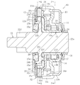
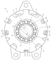
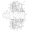
本発明に係るクラッチユニットの実施形態を図面に基づいて詳述する。図1はこの実施形態のクラッチユニットの全体構成を示す断面図、図2は図1のP-P線に沿う断面図、図3は図1のQ-Q線に沿う断面図である。この実施形態の特徴的な構成を説明する前にクラッチユニットの全体構成を説明する。
Embodiments of a clutch unit according to the present invention will be described in detail with reference to the drawings. 1 is a cross-sectional view showing the overall configuration of the clutch unit of this embodiment, FIG. 2 is a cross-sectional view taken along the line PP in FIG. 1, and FIG. 3 is a cross-sectional view taken along the line QQ in FIG. Before describing the characteristic configuration of this embodiment, the overall configuration of the clutch unit will be described.
この実施形態のクラッチユニット10は、図1に示すように、入力側に設けられたレバー側クラッチ部11と、出力側に設けられたブレーキ側クラッチ部12とをユニット化した構造を具備する。レバー側クラッチ部11は、レバー操作により入力される回転トルクの伝達および遮断を制御する。ブレーキ側クラッチ部12は、レバー側クラッチ部11からの回転トルクを出力側へ伝達すると共に、出力側から逆入力される回転トルクを遮断する逆入力遮断機能を有する。
As shown in FIG. 1, the clutch unit 10 of this embodiment has a structure in which a lever side clutch portion 11 provided on the input side and a brake side clutch portion 12 provided on the output side are unitized. The lever side clutch part 11 controls transmission and interruption of rotational torque input by lever operation. The brake-side clutch unit 12 has a reverse input blocking function for transmitting the rotational torque from the lever-side clutch unit 11 to the output side and blocking the rotational torque that is reversely input from the output side.
レバー側クラッチ部11は、図1および図2に示すように、レバー操作により回転トルクが入力される側板13および外輪14と、外輪14から入力される回転トルクをブレーキ側クラッチ部12に伝達する内輪15と、外輪14と内輪15との間での係合および離脱により外輪14からの回転トルクの伝達および遮断を制御する複数の円筒ころ16と、各円筒ころ16を円周方向等間隔に保持する保持器17と、保持器17を中立状態に復帰させるための内側センタリングばね18と、外輪14を中立状態に復帰させるための外側センタリングばね19とを具備する。
As shown in FIGS. 1 and 2, the lever side clutch unit 11 transmits to the brake side clutch unit 12 the side plate 13 and the outer ring 14 to which rotational torque is input by lever operation, and the rotational torque input from the outer ring 14. Inner ring 15, a plurality of cylindrical rollers 16 that control transmission and interruption of rotational torque from outer ring 14 by engagement and disengagement between outer ring 14 and inner ring 15, and each cylindrical roller 16 at equal intervals in the circumferential direction A retainer 17 for holding, an inner centering spring 18 for returning the retainer 17 to a neutral state, and an outer centering spring 19 for returning the outer ring 14 to a neutral state are provided.
レバー側クラッチ部11において、側板13の外周縁部に形成された爪部13aを、外輪14の外周縁部に形成された切欠き凹部14aに挿入して加締めることにより、側板13を外輪14に固定し、レバー側クラッチ部11の入力部材として一体化している。外輪14の内周には、複数のカム面14bが円周方向等間隔に形成されている。外輪14への回転トルクの入力は、側板13にねじ止め等により取り付けた上下方向揺動可能な操作レバー43(図8参照)により行われる。
In the lever side clutch part 11, the claw part 13a formed in the outer peripheral edge part of the side plate 13 is inserted into the notch recess 14a formed in the outer peripheral edge part of the outer ring 14, and the side plate 13 is tightened by tightening. And is integrated as an input member of the lever side clutch portion 11. On the inner periphery of the outer ring 14, a plurality of cam surfaces 14b are formed at equal intervals in the circumferential direction. The input of the rotational torque to the outer ring 14 is performed by an operation lever 43 (see FIG. 8) that can swing in the vertical direction and is attached to the side plate 13 by screwing or the like.
内輪15は、出力軸22が挿通される筒状部15aと、その筒状部15aのブレーキ側端部を径方向外側に延在させた拡径部15bと、その拡径部15bの外周端部を軸方向に屈曲させることにより突出した複数の柱部15c(図3参照)とからなる。内輪15の筒状部15aの外周に形成された円筒面15dと、外輪14の内周に形成されたカム面14bとの間に楔すきま20が形成され、その楔すきま20に円筒ころ16が保持器17により円周方向等間隔で配設されている。
The inner ring 15 includes a cylindrical portion 15a through which the output shaft 22 is inserted, a diameter-enlarged portion 15b in which a brake side end portion of the cylindrical portion 15a extends radially outward, and an outer peripheral end of the diameter-enlarged portion 15b. It consists of a plurality of pillars 15c (see FIG. 3) protruding by bending the part in the axial direction. A wedge clearance 20 is formed between a cylindrical surface 15 d formed on the outer periphery of the cylindrical portion 15 a of the inner ring 15 and a cam surface 14 b formed on the inner periphery of the outer ring 14, and the cylindrical roller 16 is inserted into the wedge clearance 20. The cages 17 are arranged at equal intervals in the circumferential direction.
内側センタリングばね18は、保持器17とブレーキ側クラッチ部12の静止部材であるカバー24との間に配設された断面円形のC字状弾性部材で、その両端部を保持器17およびカバー24の一部に係止させている。この内側センタリングばね18は、レバー操作により外輪14から入力される回転トルクの作用時、静止状態にあるカバー24に対して、外輪14に追従する保持器17の回転に伴って押し拡げられて弾性力が蓄積され、外輪14から入力される回転トルクの開放時、その弾性力により保持器17を中立状態に復帰させる。
The inner centering spring 18 is a C-shaped elastic member having a circular cross section disposed between the retainer 17 and a cover 24 that is a stationary member of the brake side clutch portion 12. Both ends of the inner centering spring 18 are disposed on the retainer 17 and the cover 24. It is locked to a part of. The inner centering spring 18 is elastically expanded by the rotation of the cage 17 following the outer ring 14 with respect to the cover 24 in a stationary state when the rotational torque input from the outer ring 14 is applied by lever operation. When the rotational torque input from the outer ring 14 is released, the cage 17 is returned to the neutral state by the elastic force.
内側センタリングばね18の径方向外側に位置する外側センタリングばね19は、外輪14と前述のカバー24との間に配設されたC字状帯板弾性部材で、その両端部を外輪14およびカバー24の一部に係止させている。外側センタリングばね19は、レバー操作により外輪14から入力される回転トルクの作用時、静止状態にあるカバー24に対して、外輪14の回転に伴って押し拡げられて弾性力が蓄積され、外輪14から入力される回転トルクの開放時、その弾性力により外輪14を中立状態に復帰させる。
The outer centering spring 19 positioned on the radially outer side of the inner centering spring 18 is a C-shaped strip elastic member disposed between the outer ring 14 and the above-described cover 24, and both ends thereof are arranged on the outer ring 14 and the cover 24. It is locked to a part of. The outer centering spring 19 is expanded with the rotation of the outer ring 14 with respect to the cover 24 in a stationary state when the rotational torque input from the outer ring 14 by the lever operation is applied, and an elastic force is accumulated. When the rotational torque input from is released, the outer ring 14 is returned to the neutral state by the elastic force.
保持器17は、円筒ころ16を収容する複数のポケット17aが円周方向等間隔に形成された樹脂製の円筒状部材である。この保持器17の一方の軸方向端部、つまり、ブレーキ側クラッチ部12のカバー24側の軸方向端部には、前述の内側センタリングばね18の両端部を係止させている。保持器17は、径方向で外輪14と内輪15との間に配され、軸方向で前述の外輪14とブレーキ側クラッチ部12のカバー24との間に挟み込まれている。
The cage 17 is a resin-made cylindrical member in which a plurality of pockets 17a for accommodating the cylindrical rollers 16 are formed at equal intervals in the circumferential direction. Both end portions of the inner centering spring 18 are engaged with one axial end portion of the retainer 17, that is, the axial end portion on the cover 24 side of the brake side clutch portion 12. The cage 17 is disposed between the outer ring 14 and the inner ring 15 in the radial direction, and is sandwiched between the outer ring 14 and the cover 24 of the brake side clutch portion 12 in the axial direction.
ロック型と称されるタイプで逆入力遮断機能を有するブレーキ側クラッチ部12は、図1および図3に示すように、レバー側クラッチ部11からの回転トルクが入力される入力部材としての内輪15の柱部15cと、レバー側クラッチ部11からの回転トルクが出力される出力部材としての出力軸22と、回転が拘束された静止部材としての外輪23、カバー24および側板25と、外輪23と出力軸22との間での係合および離脱により、出力軸22から逆入力される回転トルクの遮断と内輪15の柱部15cから入力される回転トルクの伝達とを制御する複数対の円筒ころ27、および各対の円筒ころ27同士に円周方向への離反力を付勢する断面N字形の板ばね28と、出力軸22に回転抵抗を付与する摩擦リング29とで主要部が構成されている。
As shown in FIGS. 1 and 3, the brake-side clutch portion 12 having a reverse input blocking function, which is called a lock type, has an inner ring 15 as an input member to which rotational torque from the lever-side clutch portion 11 is input. Column part 15c, output shaft 22 as an output member from which rotational torque from lever side clutch part 11 is output, outer ring 23, cover 24 and side plate 25 as stationary members with restricted rotation, outer ring 23, A plurality of pairs of cylindrical rollers that control the interruption of the rotational torque reversely input from the output shaft 22 and the transmission of the rotational torque input from the column portion 15c of the inner ring 15 by engagement and disengagement with the output shaft 22. 27, and a leaf spring 28 having an N-shaped cross section for biasing the circumferential separating force between the pair of cylindrical rollers 27, and a friction ring 29 for imparting rotational resistance to the output shaft 22, It has been made.
出力軸22は、内輪15の筒状部15aが外挿された軸部22aの軸方向中央部位に、径方向外側に延びて拡径した大径部22bが一体的に形成されている。軸部22aの出力側端部には、シートリフタ部41(図8参照)と連結するためのピニオンギヤ22dが同軸的に形成されている。また、軸部22aの入力側端部にウェーブワッシャ30を介してワッシャ31を圧入することにより、レバー側クラッチ部11の構成部品を抜け止めしている。
The output shaft 22 is integrally formed with a large-diameter portion 22b that extends radially outward and expands in the axial central portion of the shaft portion 22a into which the cylindrical portion 15a of the inner ring 15 is extrapolated. A pinion gear 22d for connecting to the seat lifter 41 (see FIG. 8) is formed coaxially at the output side end of the shaft 22a. Further, the washer 31 is press-fitted into the input side end portion of the shaft portion 22a via the wave washer 30 to prevent the component parts of the lever side clutch portion 11 from coming off.
出力軸22の大径部22bの外周には、複数の平坦なカム面22eが円周方向等間隔に形成されている。大径部22bのカム面22eと外輪23の円筒状内周面23aとの間で設けられた楔すきま26に、二つの円筒ころ27と二つの円筒ころ27間に介挿された一つの板ばね28とがそれぞれ配されている。出力軸22の大径部22bには、内輪15からの回転トルクを出力軸22に伝達するための突起22fが設けられている。突起22fは、内輪15の拡径部15bに形成された孔15eに円周方向のクリアランスをもって挿入配置されている(図1参照)。
A plurality of flat cam surfaces 22e are formed on the outer periphery of the large-diameter portion 22b of the output shaft 22 at equal intervals in the circumferential direction. One plate inserted between two cylindrical rollers 27 and two cylindrical rollers 27 in a wedge clearance 26 provided between the cam surface 22e of the large diameter portion 22b and the cylindrical inner peripheral surface 23a of the outer ring 23. Each of the springs 28 is arranged. The large diameter portion 22 b of the output shaft 22 is provided with a protrusion 22 f for transmitting the rotational torque from the inner ring 15 to the output shaft 22. The protrusion 22f is inserted and disposed in a hole 15e formed in the enlarged diameter portion 15b of the inner ring 15 with a circumferential clearance (see FIG. 1).
円筒ころ27および板ばね28は、内輪15の柱部15cにより円周方向等間隔に配設されている。内輪15の柱部15cは、レバー側クラッチ部11の外輪14から入力される回転トルクを出力軸22に伝達することによりブレーキ側クラッチ部12の入力部材としての機能と、円筒ころ27および板ばね28をポケット15fに収容して円周方向等間隔に保持することにより保持器としての機能を有する。以下、この内輪15の柱部15cを保持器15cと称す。
The cylindrical roller 27 and the leaf spring 28 are arranged at equal intervals in the circumferential direction by the pillar portion 15 c of the inner ring 15. The column portion 15c of the inner ring 15 transmits a rotational torque input from the outer ring 14 of the lever side clutch portion 11 to the output shaft 22, thereby functioning as an input member of the brake side clutch portion 12, and the cylindrical roller 27 and the leaf spring. 28 is accommodated in the pocket 15f and held at equal intervals in the circumferential direction to function as a cage. Hereinafter, the column portion 15c of the inner ring 15 is referred to as a cage 15c.
外輪23、カバー24および側板25は、厚肉板状の外輪23の外周縁部に形成された切欠き凹部23bと、カバー24の外周縁部に形成された切欠き凹部(図示せず)とに、側板25の外周縁部に形成された爪部25aを挿入して加締めることにより、外輪23およびカバー24に側板25を固定し、ブレーキ側クラッチ部12の静止部材として一体化されている(図3参照)。
The outer ring 23, the cover 24, and the side plate 25 include a notch recess 23 b formed in the outer peripheral edge of the thick plate-shaped outer ring 23, and a notch recess (not shown) formed in the outer peripheral edge of the cover 24. The side plate 25 is fixed to the outer ring 23 and the cover 24 by inserting and tightening a claw portion 25a formed on the outer peripheral edge of the side plate 25, and is integrated as a stationary member of the brake side clutch portion 12. (See FIG. 3).
摩擦リング29は、例えば、樹脂材を射出成形などによりリング状に形成した部材であり、側板25に固着されている。この摩擦リング29は、出力軸22の大径部22bに形成された環状凹部22cの内周面22gに締め代をもって圧入される。摩擦リング29の外周面29bと出力軸22の環状凹部22cの内周面22gとの間に生じる摩擦力によって、レバー操作時、出力軸22に回転抵抗が付与される。
The friction ring 29 is a member formed by, for example, a resin material in a ring shape by injection molding or the like, and is fixed to the side plate 25. The friction ring 29 is press-fitted to the inner peripheral surface 22g of the annular recess 22c formed in the large diameter portion 22b of the output shaft 22 with a tightening margin. Due to the frictional force generated between the outer peripheral surface 29b of the friction ring 29 and the inner peripheral surface 22g of the annular recess 22c of the output shaft 22, rotational resistance is applied to the output shaft 22 during lever operation.
以上の構成からなるレバー側クラッチ部11およびブレーキ側クラッチ部12の動作例を以下に説明する。
An operation example of the lever side clutch part 11 and the brake side clutch part 12 having the above-described configuration will be described below.
レバー側クラッチ部11では、レバー操作により外輪14に回転トルクが入力されると、円筒ころ16が外輪14と内輪15との間の楔すきま20に係合する。この楔すきま20での円筒ころ16の係合により、内輪15に回転トルクが伝達されて内輪15が回転する。この時、外輪14および保持器17の回転に伴って両センタリングばね18,19に弾性力が蓄積される。
In the lever side clutch portion 11, when rotational torque is input to the outer ring 14 by lever operation, the cylindrical roller 16 engages with the wedge clearance 20 between the outer ring 14 and the inner ring 15. Due to the engagement of the cylindrical roller 16 in the wedge clearance 20, rotational torque is transmitted to the inner ring 15 and the inner ring 15 rotates. At this time, elastic force is accumulated in the centering springs 18 and 19 as the outer ring 14 and the cage 17 rotate.
回転トルクの入力がなくなると、両センタリングばね18,19の弾性力により保持器17および外輪14が中立状態に復帰する。一方で、内輪15は、与えられた回転位置をそのまま維持する。従って、外輪14の回転繰り返し、つまり、操作レバー43のポンピング操作により、内輪15は寸動回転する。
When the rotational torque is no longer input, the cage 17 and the outer ring 14 are returned to the neutral state by the elastic force of the centering springs 18 and 19. On the other hand, the inner ring 15 maintains the given rotational position as it is. Therefore, the inner ring 15 rotates in a jog by repeating the rotation of the outer ring 14, that is, by the pumping operation of the operation lever 43.
ブレーキ側クラッチ部12では、座席シート40への着座により出力軸22に回転トルクが逆入力されても、円筒ころ27が出力軸22と外輪23との間の楔すきま26に係合して出力軸22が外輪23に対してロックされる。このようにして、出力軸22から逆入力された回転トルクは、ブレーキ側クラッチ部12によってロックされてレバー側クラッチ部11への還流が遮断される。これにより、座席シート40は固定されて上下調整が不可となる。
In the brake-side clutch portion 12, even when rotational torque is reversely input to the output shaft 22 by sitting on the seat 40, the cylindrical roller 27 engages with the wedge clearance 26 between the output shaft 22 and the outer ring 23 and outputs it. The shaft 22 is locked with respect to the outer ring 23. In this manner, the rotational torque reversely input from the output shaft 22 is locked by the brake side clutch portion 12 and the return to the lever side clutch portion 11 is blocked. As a result, the seat 40 is fixed and cannot be adjusted up and down.
一方、レバー操作によりレバー側クラッチ部11からの回転トルクが保持器15cに入力されると、保持器15cが回転し円筒ころ27と当接して板ばね28の弾性力に抗して円筒ころ27を押圧する。これにより、円筒ころ27が楔すきま26から離脱し、この楔すきま26からの円筒ころ27の離脱により出力軸22のロック状態が解除され、出力軸22は回転可能となる。この出力軸22のロック状態の解除時、摩擦リング29により出力軸22に回転抵抗が付与される。
On the other hand, when the rotational torque from the lever side clutch portion 11 is input to the retainer 15c by lever operation, the retainer 15c rotates and contacts the cylindrical roller 27 to resist the elastic force of the leaf spring 28. Press. As a result, the cylindrical roller 27 is detached from the wedge clearance 26, and the locked state of the output shaft 22 is released by the separation of the cylindrical roller 27 from the wedge clearance 26, so that the output shaft 22 can rotate. When the locked state of the output shaft 22 is released, rotational friction is applied to the output shaft 22 by the friction ring 29.
保持器15cがさらに回転すると、内輪15の拡径部15bの孔15eと出力軸22の大径部22bの突起22fとのクリアランスが詰まって内輪15の拡径部15bが出力軸22の突起22fに回転方向で当接する。これにより、レバー側クラッチ部11からの回転トルクは、突起22fを介して出力軸22に伝達されて出力軸22が回転する。つまり、保持器15cが寸動回転すると、出力軸22も寸動回転することになる。これにより、座席シート40の上下調整が可能となる。
When the cage 15c further rotates, the clearance between the hole 15e of the enlarged diameter portion 15b of the inner ring 15 and the projection 22f of the large diameter portion 22b of the output shaft 22 is clogged, and the enlarged diameter portion 15b of the inner ring 15 becomes the projection 22f of the output shaft 22. Abuts in the rotational direction. Thereby, the rotational torque from the lever side clutch part 11 is transmitted to the output shaft 22 via the protrusion 22f, and the output shaft 22 rotates. That is, when the retainer 15c is jogged and rotated, the output shaft 22 is also jogged and rotated. Thereby, the vertical adjustment of the seat 40 can be performed.
この実施形態におけるクラッチユニット10の全体構成は、前述のとおりであるが、その特徴的な構成について、以下に詳述する。
The overall configuration of the clutch unit 10 in this embodiment is as described above, and the characteristic configuration will be described in detail below.
ブレーキ側クラッチ部12での出力軸22のロック時、座席シート40(図8参照)への着座状態で、悪路などでの車両走行時に上下振動が発生すると、正方向の回転トルクと逆方向の回転トルクが交互に連続した状態で出力軸22に逆入力されることになる。このような正逆方向の回転トルクが連続して出力軸22に逆入力されても、出力軸22を確実にロックするため、以下の構造を具備する。
When the output shaft 22 is locked by the brake side clutch portion 12 and the seat is seated on the seat 40 (see FIG. 8), if vertical vibrations occur when the vehicle travels on a rough road or the like, the rotational torque in the forward direction and the reverse direction Are reversely input to the output shaft 22 in a state where the rotational torques are alternately continuous. The following structure is provided to securely lock the output shaft 22 even if such forward and reverse rotational torques are continuously input back to the output shaft 22.
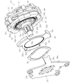
この実施形態のブレーキ側クラッチ部12において、図1および図4に示すように、回転トルクの遮断時に出力軸22と噛合し、回転トルクの伝達時に出力軸22との噛合状態が解除されるギヤ部材であるスライドギヤ32を外輪23に付設した構造を具備する。このスライドギヤ32は、出力軸22に対して軸方向移動可能に配置されている。
In the brake side clutch portion 12 of this embodiment, as shown in FIG. 1 and FIG. 4, a gear that meshes with the output shaft 22 when the rotational torque is interrupted and that is disengaged from the output shaft 22 when the rotational torque is transmitted. A structure in which a slide gear 32 as a member is attached to the outer ring 23 is provided. The slide gear 32 is disposed so as to be movable in the axial direction with respect to the output shaft 22.
このスライドギヤ32は、内周に歯部32a(以下、内歯と称す)が形成されたリング状本体32bと、そのリング状本体32bの外周の円周方向複数箇所(この実施形態では3箇所)に等間隔で径方向外側へ延設されたフランジ部32cと、そのフランジ部32cから軸方向に延びる鍔部32dとで構成されている。
The slide gear 32 includes a ring-shaped main body 32b having teeth 32a (hereinafter referred to as internal teeth) formed on the inner periphery, and a plurality of circumferential positions on the outer periphery of the ring-shaped main body 32b (three in this embodiment). ), And a flange portion 32c extending radially outward at equal intervals, and a flange portion 32d extending in the axial direction from the flange portion 32c.
これに対して、出力軸22の大径部22bの外周で、カム面22eが形成された部位よりも軸方向外側に位置する部位に、スライドギヤ32の内歯32aと対応させた歯部22h(以下、外歯と称す)が形成されている。また、外輪23の端面に、スライドギヤ32のフランジ部32cと対応させた凹部23cが形成されている。さらに、外輪23の外周面に、スライドギヤ32の鍔部32dと対応させた凹部23dが形成されている。
On the other hand, at the outer periphery of the large-diameter portion 22b of the output shaft 22, the tooth portion 22h corresponding to the internal tooth 32a of the slide gear 32 is located on the outer side in the axial direction from the portion where the cam surface 22e is formed. (Hereinafter referred to as external teeth) is formed. Further, a concave portion 23 c corresponding to the flange portion 32 c of the slide gear 32 is formed on the end surface of the outer ring 23. Further, a concave portion 23 d corresponding to the flange portion 32 d of the slide gear 32 is formed on the outer peripheral surface of the outer ring 23.
スライドギヤ32は、フランジ部32cを外輪23の端面の凹部23cに収容すると共に、鍔部32dを外輪23の外周面の凹部23dに嵌合させることにより、外輪23に組み付けられる。スライドギヤ32のフランジ部32cを外輪23の凹部23cに収容することにより、外輪23に対するスライドギヤ32の軸方向移動を許容する。また、スライドギヤ32の鍔部32dを外輪23の凹部23dに嵌合させることにより、外輪23に対するスライドギヤ32の周方向移動(回転)を規制する。
The slide gear 32 is assembled to the outer ring 23 by accommodating the flange 32c in the recess 23c on the end surface of the outer ring 23 and fitting the flange 32d into the recess 23d on the outer peripheral surface of the outer ring 23. By accommodating the flange portion 32 c of the slide gear 32 in the recess 23 c of the outer ring 23, the slide gear 32 is allowed to move in the axial direction with respect to the outer ring 23. Further, by engaging the flange portion 32 d of the slide gear 32 with the recess 23 d of the outer ring 23, circumferential movement (rotation) of the slide gear 32 with respect to the outer ring 23 is restricted.
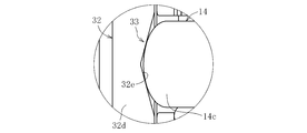
一方、スライドギヤ32を軸方向に移動させて出力軸22との噛合および噛合状態の解除を制御するカム機構33を、スライドギヤ32とレバー側クラッチ部11の外輪14との間に介在させている。このカム機構33は、図5および図6に示すように、スライドギヤ32の鍔部32dの端面に形成されたV字状のカム溝32eと、レバー側クラッチ部11の外輪14の外周から軸方向に延びる凸部14cとで構成されている。カム機構33では、外輪14の凸部14cの先端曲成部をスライドギヤ32のカム溝32eのカム面に当接させている。
On the other hand, a cam mechanism 33 that moves the slide gear 32 in the axial direction and controls the engagement with the output shaft 22 and the release of the engagement state is interposed between the slide gear 32 and the outer ring 14 of the lever side clutch portion 11. Yes. As shown in FIGS. 5 and 6, the cam mechanism 33 has a V-shaped cam groove 32 e formed on the end surface of the flange portion 32 d of the slide gear 32 and an outer periphery of the outer ring 14 of the lever side clutch portion 11. It is comprised with the convex part 14c extended in a direction. In the cam mechanism 33, the tip bent portion of the convex portion 14 c of the outer ring 14 is brought into contact with the cam surface of the cam groove 32 e of the slide gear 32.
また、図1および図4に示すように、ブレーキ側クラッチ部12の側板25とスライドギヤ32との間に、スライドギヤ32を出力軸22と噛合する方向に弾性的に付勢する弾性部材34を介在させている。この弾性部材34としては、例えば、図示のようなリング状の波ばねなどが好適である。弾性部材34の弾性力によりスライドギヤ32を外輪23に押圧することで、スライドギヤ32の内歯32aと出力軸22の外歯22hとを噛合させるようにしている。
Further, as shown in FIGS. 1 and 4, an elastic member 34 that elastically urges the slide gear 32 in a direction to mesh with the output shaft 22 between the side plate 25 of the brake side clutch portion 12 and the slide gear 32. Is interposed. As the elastic member 34, for example, a ring-shaped wave spring as illustrated is suitable. By pressing the slide gear 32 against the outer ring 23 by the elastic force of the elastic member 34, the inner teeth 32 a of the slide gear 32 and the outer teeth 22 h of the output shaft 22 are engaged with each other.
この実施形態のクラッチユニット10において、レバー側クラッチ部11の外輪14から回転トルクが入力されていない状態では、外側センタリングばね19により外輪14が中立状態に維持されている。
In the clutch unit 10 of this embodiment, the outer ring 14 is maintained in a neutral state by the outer centering spring 19 when no rotational torque is input from the outer ring 14 of the lever side clutch portion 11.
この時、ブレーキ側クラッチ部12のカム機構33では、レバー側クラッチ部11の外輪14の凸部14cとスライドギヤ32のカム溝23eとが中立位置にあるため(図5および図6参照)、スライドギヤ32が弾性部材34の弾性力により軸方向に押圧され、スライドギヤ32の内歯32aと出力軸22の外歯22hとが噛合する(図1参照)。これにより、出力軸22がロック状態となる。
At this time, in the cam mechanism 33 of the brake side clutch portion 12, the convex portion 14c of the outer ring 14 of the lever side clutch portion 11 and the cam groove 23e of the slide gear 32 are in the neutral position (see FIGS. 5 and 6). The slide gear 32 is pressed in the axial direction by the elastic force of the elastic member 34, and the inner teeth 32a of the slide gear 32 and the outer teeth 22h of the output shaft 22 mesh (see FIG. 1). As a result, the output shaft 22 is locked.
この出力軸22のロック状態において、座席シート40(図8参照)への着座状態で、悪路などでの車両走行時に上下振動が発生し、その上下振動により、正方向の回転トルクと逆方向の回転トルクが交互に連続した状態で出力軸22に逆入力されても、スライドギヤ32の内歯32aが出力軸22の外歯22hに噛合していることで、その出力軸22を確実にロックすることができる。
In the locked state of the output shaft 22, vertical vibrations are generated when the vehicle is traveling on a rough road or the like while being seated on the seat 40 (see FIG. 8). Even if the rotation torque of the slide gear 32 is reversely input to the output shaft 22, the internal teeth 32a of the slide gear 32 are engaged with the external teeth 22h of the output shaft 22, so that the output shaft 22 is securely connected. Can be locked.
ブレーキ側クラッチ部12では、外輪23と出力軸22との間で円筒ころ27の接触位置が微妙にずれたり、回転トルクが負荷される出力軸22、外輪23、円筒ころ27に弾性変形のヒステリシスが存在したりしても、スライドギヤ32の内歯32aと出力軸22の外歯22hとの噛み合いにより、出力軸22が徐々に回転することを回避できるので、座席シート40が微小に下がる現象の発生を防止することができる。また、スライドギヤ32と出力軸22との噛み合いにより、ブレーキ側クラッチ部12に対して大容量のトルク負荷が可能となる。
In the brake side clutch portion 12, the contact position of the cylindrical roller 27 is slightly shifted between the outer ring 23 and the output shaft 22, or the output shaft 22, the outer ring 23, and the cylindrical roller 27 to which rotational torque is applied are subjected to hysteresis of elastic deformation. Even if there is, there is a phenomenon in which the seat 40 is slightly lowered because the output shaft 22 can be prevented from gradually rotating due to the engagement between the inner teeth 32a of the slide gear 32 and the outer teeth 22h of the output shaft 22. Can be prevented. Further, the engagement of the slide gear 32 and the output shaft 22 enables a large-capacity torque load to the brake-side clutch portion 12.
この実施形態では、ブレーキ側クラッチ部12の側板25とスライドギヤ32との間に、スライドギヤ32を出力軸22と噛合する方向に弾性的に付勢する弾性部材34を介在させた構造を採用していることから、弾性部材34の弾性力によりスライドギヤ32を外輪23に押圧することで、スライドギヤ32の内歯32aと出力軸22の外歯22hとの噛合状態を安定させることができる。
In this embodiment, a structure in which an elastic member 34 that elastically urges the slide gear 32 in a direction to mesh with the output shaft 22 is interposed between the side plate 25 of the brake side clutch portion 12 and the slide gear 32 is employed. Therefore, the meshing state of the internal teeth 32a of the slide gear 32 and the external teeth 22h of the output shaft 22 can be stabilized by pressing the slide gear 32 against the outer ring 23 by the elastic force of the elastic member 34. .
一方、レバー側クラッチ部11の外輪14から回転トルクが入力されると、ブレーキ側クラッチ部12のカム機構33では、外輪14の凸部14cとスライドギヤ32の鍔部32dのカム溝32eとが位相ずれする。この凸部14cとカム溝32eとの位相ずれにより、図7に示すように、スライドギヤ32が弾性部材34の弾性力に抗して側板25に近接するように軸方向に移動する(図中白抜き矢印参照)。
On the other hand, when rotational torque is input from the outer ring 14 of the lever side clutch portion 11, the cam mechanism 33 of the brake side clutch portion 12 causes the convex portion 14 c of the outer ring 14 and the cam groove 32 e of the flange portion 32 d of the slide gear 32. Out of phase. Due to the phase shift between the convex portion 14c and the cam groove 32e, the slide gear 32 moves in the axial direction so as to approach the side plate 25 against the elastic force of the elastic member 34 as shown in FIG. See white arrow).
このスライドギヤ32の軸方向移動により、出力軸22の外歯22hからスライドギヤ32の内歯32aが離脱し、スライドギヤ32の内歯32aと出力軸22の外歯22hとの噛合状態が解除される。これにより、出力軸22は外輪23に対して回転可能な状態となる。
Due to the axial movement of the slide gear 32, the internal teeth 32a of the slide gear 32 are disengaged from the external teeth 22h of the output shaft 22, and the meshing state between the internal teeth 32a of the slide gear 32 and the external teeth 22h of the output shaft 22 is released. Is done. As a result, the output shaft 22 becomes rotatable with respect to the outer ring 23.
なお、スライドギヤ32の内歯32aが出力軸22の外歯22hから完全に離脱して出力軸22が回転可能な状態となるまで、ブレーキ側クラッチ部12では、円筒ころ27の係合が内輪15により解除されないようにする必要がある。
It should be noted that until the inner teeth 32a of the slide gear 32 are completely disengaged from the outer teeth 22h of the output shaft 22 and the output shaft 22 becomes rotatable, the engagement of the cylindrical rollers 27 is engaged in the brake-side clutch portion 12. It is necessary not to be released by 15.
この実施形態では、スライドギヤ32を軸方向に移動させて出力軸22との噛合および噛合状態の解除を制御するカム機構33(外輪14の凸部14cとスライドギヤ32の鍔部32dのカム溝32e)を、スライドギヤ32と外輪14との間に介在させた構造を採用していることから、スライドギヤ32と出力軸22との噛合および噛合状態の解除を容易に行うことができる。
In this embodiment, the cam mechanism 33 (the cam groove of the convex portion 14c of the outer ring 14 and the flange portion 32d of the slide gear 32) that controls the engagement with the output shaft 22 and the release of the engagement state by moving the slide gear 32 in the axial direction. 32e) is employed between the slide gear 32 and the outer ring 14, so that the engagement between the slide gear 32 and the output shaft 22 and the release of the engagement state can be easily performed.
また、スライドギヤ32の内歯32aが出力軸22の外歯22hから離脱した直後、ブレーキ側クラッチ部12では、円筒ころ27が外輪23と出力軸22との間の楔すきま26に係合した状態にある。そのため、この時点で出力軸22に回転トルクが逆入力されても、出力軸22が確実にロックされている。
Further, immediately after the inner teeth 32 a of the slide gear 32 are disengaged from the outer teeth 22 h of the output shaft 22, the cylindrical roller 27 is engaged with the wedge clearance 26 between the outer ring 23 and the output shaft 22 in the brake-side clutch portion 12. Is in a state. Therefore, even if the rotational torque is reversely input to the output shaft 22 at this time, the output shaft 22 is securely locked.
その後、スライドギヤ32の軸方向移動によりスライドギヤ32の内歯32aが出力軸22の外歯22hから完全に離脱した時点で、円筒ころ27が外輪23と出力軸22との間の楔すきま26から離脱するので、レバー操作時にスライドギヤ32と出力軸22との間で歯打ち音などの異音が発生することはない。
Thereafter, when the inner teeth 32a of the slide gear 32 are completely separated from the outer teeth 22h of the output shaft 22 due to the axial movement of the slide gear 32, the cylindrical roller 27 is separated from the outer ring 23 and the output shaft 22 by the wedge clearance 26. Therefore, no abnormal noise such as rattling noise is generated between the slide gear 32 and the output shaft 22 when the lever is operated.
以上のことから、ブレーキ側クラッチ部12では、スライドギヤ32の内歯32aと出力軸22の外歯22hとが噛み合う構造だけでなく、円筒ころ27が外輪23と出力軸22との間の楔すきま26で係合する構造も必要となる。
From the above, in the brake-side clutch portion 12, not only the structure in which the inner teeth 32 a of the slide gear 32 and the outer teeth 22 h of the output shaft 22 mesh with each other, but the cylindrical roller 27 has a wedge between the outer ring 23 and the output shaft 22. A structure that engages with the clearance 26 is also required.
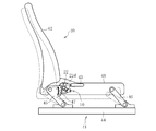
最後に、この実施形態のクラッチユニット10の適用例を説明する。以上で詳述した構造を具備するクラッチユニット10は、レバー操作により座席シートの高さ調整を行う自動車用シートリフタ部41に組み込まれて使用される。図8は自動車の乗員室に装備される座席シート40を示す。
Finally, an application example of the clutch unit 10 of this embodiment will be described. The clutch unit 10 having the structure described in detail above is used by being incorporated in an automobile seat lifter 41 that adjusts the height of a seat by lever operation. FIG. 8 shows a seat 40 installed in the passenger compartment of the automobile.
座席シート40は、図8に示すように、着座シート48と背もたれシート42とで構成され、シートリフタ部41により着座シート48の座面を高さ調整する。着座シート48の高さ調整は、クラッチユニット10におけるレバー側クラッチ部11(図1参照)の側板13に取り付けられた操作レバー43によって行う。
As shown in FIG. 8, the seat 40 is composed of a seating seat 48 and a backrest seat 42, and the seat lifter 41 adjusts the height of the seating surface of the seating seat 48. The height of the seating seat 48 is adjusted by the operation lever 43 attached to the side plate 13 of the lever side clutch portion 11 (see FIG. 1) in the clutch unit 10.
シートリフタ部41は、以下の構造を具備する。スライド可動部材44にリンク部材45,46の一端がそれぞれ回動自在に枢着されている。リンク部材45,46の他端はそれぞれ着座シート48に回動自在に枢着されている。リンク部材45の他端にはセクターギヤ47が一体的に設けられている。セクターギヤ47はクラッチユニット10の出力軸22のピニオンギヤ22dに噛合している。
The sheet lifter 41 has the following structure. One end of each of the link members 45 and 46 is pivotally attached to the slide movable member 44 so as to be rotatable. The other ends of the link members 45 and 46 are pivotally attached to the seating seat 48, respectively. A sector gear 47 is integrally provided at the other end of the link member 45. The sector gear 47 meshes with the pinion gear 22 d of the output shaft 22 of the clutch unit 10.
例えば、着座シート48の座面を低くする場合、レバー側クラッチ部11でのレバー操作、つまり、操作レバー43を下側へ揺動させることにより、ブレーキ側クラッチ部12(図1参照)のロック状態を解除する。このブレーキ側クラッチ部12でのロック解除時、摩擦リング29により出力軸22に適正な回転抵抗を付与することで、着座シート48の座面をスムーズに低くすることができる。
For example, when lowering the seating surface of the seating seat 48, the lever side clutch portion 11 is operated, that is, the operation lever 43 is swung downward to lock the brake side clutch portion 12 (see FIG. 1). Release the state. When the brake side clutch portion 12 is unlocked, the friction ring 29 gives the output shaft 22 an appropriate rotational resistance, so that the seating surface of the seating seat 48 can be lowered smoothly.
ブレーキ側クラッチ部12でのロック解除により、レバー側クラッチ部11からブレーキ側クラッチ部12に伝達された回転トルクでもって、ブレーキ側クラッチ部12の出力軸22のピニオンギヤ22dが時計方向(図8の矢印方向)に回動する。そして、ピニオンギヤ22dと噛合するセクターギヤ47が反時計方向(図8の矢印方向)に揺動し、リンク部材45とリンク部材46が共に傾倒して着座シート48の座面が低くなる。
By releasing the lock at the brake side clutch portion 12, the pinion gear 22d of the output shaft 22 of the brake side clutch portion 12 is rotated clockwise (in FIG. 8) with the rotational torque transmitted from the lever side clutch portion 11 to the brake side clutch portion 12. It rotates in the direction of the arrow. Then, the sector gear 47 that meshes with the pinion gear 22d swings counterclockwise (the arrow direction in FIG. 8), and both the link member 45 and the link member 46 are tilted to lower the seating surface of the seating seat 48.
このようにして、着座シート48の座面を高さ調整した後、操作レバー43を開放すると、操作レバー43が両センタリングばね18,19の弾性力によって上側へ揺動して元の位置(中立状態)に戻る。なお、操作レバー43を上側へ揺動させた場合は、前述とは逆の動作で着座シート48の座面が高くなる。着座シート48の高さ調整後に操作レバー43を開放すると、操作レバー43が下側へ揺動して元の位置(中立状態)に戻る。
In this way, after adjusting the height of the seating surface of the seating seat 48, when the operation lever 43 is released, the operation lever 43 is swung upward by the elastic force of the centering springs 18 and 19 to return to the original position (neutral). Return to the state. When the operation lever 43 is swung upward, the seating surface of the seating seat 48 is raised by the reverse operation to that described above. When the operation lever 43 is released after the height of the seating seat 48 is adjusted, the operation lever 43 swings downward and returns to the original position (neutral state).
本発明は前述した実施形態に何ら限定されるものではなく、本発明の要旨を逸脱しない範囲内において、さらに種々なる形態で実施し得ることは勿論のことであり、本発明の範囲は、請求の範囲によって示され、さらに請求の範囲に記載の均等の意味、および範囲内のすべての変更を含む。
The present invention is not limited to the above-described embodiments, and can of course be implemented in various forms without departing from the gist of the present invention. The equivalent meanings recited in the claims, and all modifications within the scope.
Claims (4)
- 入力側に設けられ、レバー操作により入力される回転トルクの伝達および遮断を制御するレバー側クラッチ部と、出力側に設けられ、レバー側クラッチ部からの回転トルクを出力側へ伝達すると共に、出力側から逆入力される回転トルクを遮断するブレーキ側クラッチ部とからなり、
前記ブレーキ側クラッチ部は、回転が拘束された静止部材と、回転が出力される出力部材と、静止部材と出力部材との間に配置され、前記レバー側クラッチ部からの回転トルクが入力される入力部材と、静止部材と出力部材との間での係合および離脱により、出力部材から逆入力される回転トルクの遮断と入力部材から入力される回転トルクの伝達とを制御する係合子とを備え、
前記静止部材に、回転トルクの遮断時に出力部材と噛合し、かつ、回転トルクの伝達時に出力部材との噛合状態が解除されるギヤ部材を付設したことを特徴とするクラッチユニット。 Provided on the input side and controls the transmission and shut-off of the rotational torque input by lever operation, and provided on the output side, transmits the rotational torque from the lever side clutch to the output side, and outputs It consists of a brake side clutch part that cuts off rotational torque that is reversely input from the side,
The brake side clutch portion is disposed between a stationary member whose rotation is constrained, an output member from which rotation is output, and the stationary member and the output member, and receives rotational torque from the lever side clutch portion. An input member and an engagement member for controlling the interruption of the rotational torque input from the output member and the transmission of the rotational torque input from the input member by engagement and disengagement between the stationary member and the output member. Prepared,
A clutch unit, wherein the stationary member is provided with a gear member that meshes with the output member when the rotational torque is interrupted and that releases the meshed state with the output member when the rotational torque is transmitted. - 前記ギヤ部材は、出力部材に対して軸方向移動可能に配置された構造を有し、前記ギヤ部材を軸方向に移動させて出力部材との噛合および噛合状態の解除を制御するカム機構を、ギヤ部材と前記レバー側クラッチ部の入力部材との間に介在させた請求項1に記載のクラッチユニット。 The gear member has a structure arranged so as to be axially movable with respect to the output member, and a cam mechanism that controls the engagement with the output member and the release of the meshing state by moving the gear member in the axial direction, The clutch unit according to claim 1, wherein the clutch unit is interposed between a gear member and an input member of the lever side clutch portion.
- 前記静止部材とギヤ部材との間に、前記ギヤ部材を出力部材と噛合する方向に弾性的に付勢する弾性部材を介在させた請求項1又は2に記載のクラッチユニット。 The clutch unit according to claim 1 or 2, wherein an elastic member that elastically biases the gear member in a direction to mesh with the output member is interposed between the stationary member and the gear member.
- 前記レバー側クラッチ部と前記ブレーキ側クラッチ部が自動車用シートリフタ部に組み込まれている請求項1~3のいずれか一項に記載のクラッチユニット。 The clutch unit according to any one of claims 1 to 3, wherein the lever side clutch portion and the brake side clutch portion are incorporated in an automobile seat lifter portion.
Priority Applications (3)
| Application Number | Priority Date | Filing Date | Title |
|---|---|---|---|
| EP17766433.1A EP3460280B1 (en) | 2016-03-18 | 2017-03-06 | Clutch unit |
| CN201780010479.9A CN108603545B (en) | 2016-03-18 | 2017-03-06 | Clutch unit |
| US16/075,725 US10711851B2 (en) | 2016-03-18 | 2017-03-06 | Clutch unit |
Applications Claiming Priority (2)
| Application Number | Priority Date | Filing Date | Title |
|---|---|---|---|
| JP2016-055511 | 2016-03-18 | ||
| JP2016055511A JP6665000B2 (en) | 2016-03-18 | 2016-03-18 | Clutch unit |
Publications (1)
| Publication Number | Publication Date |
|---|---|
| WO2017159431A1 true WO2017159431A1 (en) | 2017-09-21 |
Family
ID=59850689
Family Applications (1)
| Application Number | Title | Priority Date | Filing Date |
|---|---|---|---|
| PCT/JP2017/008797 WO2017159431A1 (en) | 2016-03-18 | 2017-03-06 | Clutch unit |
Country Status (5)
| Country | Link |
|---|---|
| US (1) | US10711851B2 (en) |
| EP (1) | EP3460280B1 (en) |
| JP (1) | JP6665000B2 (en) |
| CN (1) | CN108603545B (en) |
| WO (1) | WO2017159431A1 (en) |
Cited By (2)
| Publication number | Priority date | Publication date | Assignee | Title |
|---|---|---|---|---|
| JP2020041665A (en) * | 2018-09-13 | 2020-03-19 | Ntn株式会社 | Clutch unit |
| US11486458B2 (en) * | 2018-01-30 | 2022-11-01 | Ntn Corporation | Clutch unit |
Families Citing this family (12)
| Publication number | Priority date | Publication date | Assignee | Title |
|---|---|---|---|---|
| JP6636366B2 (en) * | 2016-03-22 | 2020-01-29 | Ntn株式会社 | Clutch unit |
| US20190028008A1 (en) * | 2017-07-18 | 2019-01-24 | Hyundai Mobis Co., Ltd | In-wheel working device |
| WO2019059287A1 (en) * | 2017-09-21 | 2019-03-28 | Ntn株式会社 | Clutch unit |
| JP7094178B2 (en) | 2017-09-21 | 2022-07-01 | Ntn株式会社 | Clutch unit |
| WO2019151261A1 (en) * | 2018-01-30 | 2019-08-08 | Ntn株式会社 | Clutch unit |
| CN110145556B (en) * | 2018-02-13 | 2024-03-15 | 福州明芳汽车部件工业有限公司 | Improved braking mechanism of seat height adjusting device |
| JP2020044855A (en) * | 2018-09-14 | 2020-03-26 | 株式会社Tf−Metal | Brake control system of seat for vehicle |
| DE202018105885U1 (en) * | 2018-10-15 | 2020-01-20 | Rollax Gmbh & Co. Kg | Adjustable armrest |
| US11077948B2 (en) * | 2019-04-10 | 2021-08-03 | B/E Aerospace, Inc. | Rotary backrest recline mechanism |
| KR102263734B1 (en) | 2019-06-05 | 2021-06-11 | 현대트랜시스 주식회사 | Eccentrictiy prevention device for pumping device |
| KR102299296B1 (en) * | 2019-07-03 | 2021-09-08 | 현대트랜시스 주식회사 | Pumping device for seat of vehicle |
| JP2021024343A (en) * | 2019-07-31 | 2021-02-22 | デルタ工業株式会社 | Clutch mechanism and seat structure |
Citations (3)
| Publication number | Priority date | Publication date | Assignee | Title |
|---|---|---|---|---|
| US6212965B1 (en) * | 1998-01-30 | 2001-04-10 | INA Wälzlager Schaeffler oHG | Shiftable clamping-type locking mechanism |
| JP2009210117A (en) * | 2008-03-06 | 2009-09-17 | Ntn Corp | Clutch unit |
| JP2015534018A (en) * | 2012-10-12 | 2015-11-26 | ジョンソン・コントロールズ・ゲー・エム・ベー・ハー | Equipment for adjusting automotive interior parts |
Family Cites Families (18)
| Publication number | Priority date | Publication date | Assignee | Title |
|---|---|---|---|---|
| JPS527779B2 (en) | 1972-11-20 | 1977-03-04 | ||
| CN100451373C (en) * | 2000-08-08 | 2009-01-14 | 株式会社Ntn | Clutch unit |
| JP2006189139A (en) * | 2005-01-07 | 2006-07-20 | Ntn Corp | Clutch unit |
| JP2008075776A (en) * | 2006-09-21 | 2008-04-03 | Ntn Corp | Clutch unit |
| EP2169249B1 (en) * | 2007-07-24 | 2019-09-04 | NTN Corporation | Clutch unit |
| WO2009110380A1 (en) | 2008-03-06 | 2009-09-11 | Ntn株式会社 | Clutch unit |
| CN104533985B (en) * | 2010-02-18 | 2017-07-07 | Ntn株式会社 | Clutch unit |
| CN104832562B (en) * | 2010-03-15 | 2017-11-10 | Ntn株式会社 | Clutch unit |
| JP2012031912A (en) * | 2010-07-29 | 2012-02-16 | Ntn Corp | Clutch unit |
| KR101173469B1 (en) | 2011-01-20 | 2012-08-14 | 주식회사다스 | Apparatus for preventing back-drive of pumping device for vehicle seat |
| JP5717283B2 (en) * | 2011-03-09 | 2015-05-13 | Ntn株式会社 | Clutch unit |
| DE102012006059B4 (en) | 2011-11-30 | 2014-04-24 | Johnson Controls Gmbh | Adjustment device for a motor vehicle component |
| EP2835550B1 (en) * | 2012-04-02 | 2019-05-08 | NTN Corporation | Rotation transmission device |
| JP5944213B2 (en) | 2012-04-20 | 2016-07-05 | Ntn株式会社 | Clutch unit |
| KR102043668B1 (en) * | 2012-04-20 | 2019-11-12 | 엔티엔 가부시키가이샤 | Clutch unit |
| JP6636366B2 (en) * | 2016-03-22 | 2020-01-29 | Ntn株式会社 | Clutch unit |
| JP6789726B2 (en) * | 2016-08-30 | 2020-11-25 | Ntn株式会社 | Clutch unit |
| JP6738691B2 (en) * | 2016-08-30 | 2020-08-12 | Ntn株式会社 | Clutch unit |
-
2016
- 2016-03-18 JP JP2016055511A patent/JP6665000B2/en active Active
-
2017
- 2017-03-06 WO PCT/JP2017/008797 patent/WO2017159431A1/en active Application Filing
- 2017-03-06 EP EP17766433.1A patent/EP3460280B1/en active Active
- 2017-03-06 CN CN201780010479.9A patent/CN108603545B/en active Active
- 2017-03-06 US US16/075,725 patent/US10711851B2/en active Active
Patent Citations (3)
| Publication number | Priority date | Publication date | Assignee | Title |
|---|---|---|---|---|
| US6212965B1 (en) * | 1998-01-30 | 2001-04-10 | INA Wälzlager Schaeffler oHG | Shiftable clamping-type locking mechanism |
| JP2009210117A (en) * | 2008-03-06 | 2009-09-17 | Ntn Corp | Clutch unit |
| JP2015534018A (en) * | 2012-10-12 | 2015-11-26 | ジョンソン・コントロールズ・ゲー・エム・ベー・ハー | Equipment for adjusting automotive interior parts |
Non-Patent Citations (1)
| Title |
|---|
| See also references of EP3460280A4 * |
Cited By (2)
| Publication number | Priority date | Publication date | Assignee | Title |
|---|---|---|---|---|
| US11486458B2 (en) * | 2018-01-30 | 2022-11-01 | Ntn Corporation | Clutch unit |
| JP2020041665A (en) * | 2018-09-13 | 2020-03-19 | Ntn株式会社 | Clutch unit |
Also Published As
| Publication number | Publication date |
|---|---|
| EP3460280A1 (en) | 2019-03-27 |
| EP3460280A4 (en) | 2019-12-25 |
| US10711851B2 (en) | 2020-07-14 |
| CN108603545A (en) | 2018-09-28 |
| US20190032728A1 (en) | 2019-01-31 |
| EP3460280B1 (en) | 2021-05-05 |
| JP2017172590A (en) | 2017-09-28 |
| CN108603545B (en) | 2020-09-29 |
| JP6665000B2 (en) | 2020-03-13 |
Similar Documents
| Publication | Publication Date | Title |
|---|---|---|
| WO2017159431A1 (en) | Clutch unit | |
| WO2017163859A1 (en) | Clutch unit | |
| WO2018042990A1 (en) | Clutch unit | |
| JP6324749B2 (en) | Clutch unit | |
| WO2018042991A1 (en) | Clutch unit | |
| JP6577105B2 (en) | Clutch unit | |
| WO2018042992A1 (en) | Clutch unit | |
| JP6474871B1 (en) | Clutch unit | |
| JP2018004008A (en) | Clutch unit | |
| WO2019151261A1 (en) | Clutch unit | |
| JP6509983B2 (en) | Clutch unit | |
| WO2017150401A1 (en) | Clutch unit | |
| JP2019007543A (en) | Clutch unit | |
| JP2019039465A (en) | Clutch unit | |
| JP2018119647A (en) | Clutch unit | |
| JP7094178B2 (en) | Clutch unit | |
| WO2020255973A1 (en) | Clutch unit | |
| JP2018155322A (en) | Clutch unit | |
| WO2017038548A1 (en) | Clutch unit | |
| JP2017219173A (en) | Clutch unit | |
| JP2019044859A (en) | Clutch unit | |
| JP2017137914A (en) | Clutch unit | |
| JP2020101258A (en) | Clutch unit | |
| JP2012026503A (en) | Clutch unit | |
| JP2016211611A (en) | Clutch unit |
Legal Events
| Date | Code | Title | Description |
|---|---|---|---|
| NENP | Non-entry into the national phase |
Ref country code: DE |
|
| WWE | Wipo information: entry into national phase |
Ref document number: 2017766433 Country of ref document: EP |
|
| ENP | Entry into the national phase |
Ref document number: 2017766433 Country of ref document: EP Effective date: 20181018 |
|
| 121 | Ep: the epo has been informed by wipo that ep was designated in this application |
Ref document number: 17766433 Country of ref document: EP Kind code of ref document: A1 |