WO2017158778A1 - ダンプトラック用ダンプボディおよびダンプトラック - Google Patents
ダンプトラック用ダンプボディおよびダンプトラック Download PDFInfo
- Publication number
- WO2017158778A1 WO2017158778A1 PCT/JP2016/058412 JP2016058412W WO2017158778A1 WO 2017158778 A1 WO2017158778 A1 WO 2017158778A1 JP 2016058412 W JP2016058412 W JP 2016058412W WO 2017158778 A1 WO2017158778 A1 WO 2017158778A1
- Authority
- WO
- WIPO (PCT)
- Prior art keywords
- inclined surface
- surface portion
- chassis
- dump
- dump body
- Prior art date
- Legal status (The legal status is an assumption and is not a legal conclusion. Google has not performed a legal analysis and makes no representation as to the accuracy of the status listed.)
- Ceased
Links
Images


Classifications
-
- B—PERFORMING OPERATIONS; TRANSPORTING
- B60—VEHICLES IN GENERAL
- B60P—VEHICLES ADAPTED FOR LOAD TRANSPORTATION OR TO TRANSPORT, TO CARRY, OR TO COMPRISE SPECIAL LOADS OR OBJECTS
- B60P1/00—Vehicles predominantly for transporting loads and modified to facilitate loading, consolidating the load, or unloading
- B60P1/04—Vehicles predominantly for transporting loads and modified to facilitate loading, consolidating the load, or unloading with a tipping movement of load-transporting element
- B60P1/28—Tipping body constructions
-
- B—PERFORMING OPERATIONS; TRANSPORTING
- B60—VEHICLES IN GENERAL
- B60P—VEHICLES ADAPTED FOR LOAD TRANSPORTATION OR TO TRANSPORT, TO CARRY, OR TO COMPRISE SPECIAL LOADS OR OBJECTS
- B60P1/00—Vehicles predominantly for transporting loads and modified to facilitate loading, consolidating the load, or unloading
- B60P1/04—Vehicles predominantly for transporting loads and modified to facilitate loading, consolidating the load, or unloading with a tipping movement of load-transporting element
- B60P1/28—Tipping body constructions
- B60P1/283—Elements of tipping devices
- B60P1/286—Loading buckets
-
- B—PERFORMING OPERATIONS; TRANSPORTING
- B60—VEHICLES IN GENERAL
- B60P—VEHICLES ADAPTED FOR LOAD TRANSPORTATION OR TO TRANSPORT, TO CARRY, OR TO COMPRISE SPECIAL LOADS OR OBJECTS
- B60P1/00—Vehicles predominantly for transporting loads and modified to facilitate loading, consolidating the load, or unloading
- B60P1/04—Vehicles predominantly for transporting loads and modified to facilitate loading, consolidating the load, or unloading with a tipping movement of load-transporting element
-
- B—PERFORMING OPERATIONS; TRANSPORTING
- B60—VEHICLES IN GENERAL
- B60P—VEHICLES ADAPTED FOR LOAD TRANSPORTATION OR TO TRANSPORT, TO CARRY, OR TO COMPRISE SPECIAL LOADS OR OBJECTS
- B60P1/00—Vehicles predominantly for transporting loads and modified to facilitate loading, consolidating the load, or unloading
- B60P1/04—Vehicles predominantly for transporting loads and modified to facilitate loading, consolidating the load, or unloading with a tipping movement of load-transporting element
- B60P1/16—Vehicles predominantly for transporting loads and modified to facilitate loading, consolidating the load, or unloading with a tipping movement of load-transporting element actuated by fluid-operated mechanisms
-
- B—PERFORMING OPERATIONS; TRANSPORTING
- B60—VEHICLES IN GENERAL
- B60P—VEHICLES ADAPTED FOR LOAD TRANSPORTATION OR TO TRANSPORT, TO CARRY, OR TO COMPRISE SPECIAL LOADS OR OBJECTS
- B60P1/00—Vehicles predominantly for transporting loads and modified to facilitate loading, consolidating the load, or unloading
- B60P1/04—Vehicles predominantly for transporting loads and modified to facilitate loading, consolidating the load, or unloading with a tipping movement of load-transporting element
- B60P1/28—Tipping body constructions
- B60P1/283—Elements of tipping devices
Definitions
- the present invention relates to a dump body for a dump truck and a dump truck.
- a dump truck in which the center of gravity position of a load is set at substantially the center of a wheel base is known (see, for example, Patent Document 1). According to such a dump truck, since the center of gravity is set at the approximate center of the wheel base, it becomes easier to load earth and sand with a loading machine such as a hydraulic excavator, and the spillage can be reduced. There is an effect that the load applied to the rear wheel can be made uniform.
- An object of the present invention is to provide a dump body for a dump truck and a dump truck that have a good load flow and are difficult to disperse a load such as earth and sand during discharging.
- the dump truck dump body according to the present invention includes a first inclined surface portion that rises upward from the bottom toward the soil discharge side, and a second inclined surface portion that is inclined downward from the upper end of the first inclined surface portion toward the soil discharge side end. It is characterized by having.
- a dump truck according to the present invention is a dump truck that travels forward and backward in both directions and discharges in one direction, and includes a chassis in which an engine is provided in a wheelbase, a total length in the traveling direction of the chassis, and a vehicle width direction.
- a dump body that covers the upper part of the chassis over the entire width of the chassis and is supported in a undulating manner via a hinge on the soil discharge side of the chassis, and the dump body is located above the bottom of the dump body on the soil discharge side.
- a second inclined surface portion inclined downward from the upper end of the first inclined surface portion toward the soil discharge side end portion, and when the dump body is raised, the dump body is discharged.
- the height of the soil-side end is equal to the radius of the tire of the chassis.
- the dump body is provided with the first inclined surface portion, it is possible to promptly guide loads such as earth and sand at the time of earth discharging and improve the load flow.
- the soil discharge side end portion of the dump body can be positioned closer to the ground at the time of soil removal, so that load such as earth and sand is hardly scattered at the time of soil removal. be able to.
- the dump body includes a third inclined surface portion that rises upward from the bottom of the dump body on the opposite side of the first inclined surface portion of the dump body, and the rising angle of the third inclined surface portion from the horizontal plane is It is preferable that the rising angle of the first inclined surface portion from the horizontal plane is larger.
- the dimension from the upper end of the said 1st inclined surface part to the center of the front-back direction of the said chassis is larger than the center dimension from the upper end of the said 3rd inclined surface part to the front-back direction of the said chassis.
- the perspective view which shows the dump truck which concerns on embodiment of this invention The side view of the dump truck seen from the vehicle width direction in the said embodiment.
- FIGS. 1 to 4 show a dump truck 1 according to an embodiment of the present invention.
- 1 is a perspective view
- FIG. 2 is a side view seen from the vehicle width direction orthogonal to the running direction
- FIG. 3 is a plan view seen from the upper viewpoint
- FIG. 4 is a side view seen from the running direction. It is.
- the X axis, Y axis, and Z axis in the present embodiment shown in the drawings are in a relationship of being orthogonal to each other.
- one of the traveling directions of the dump truck 1 is the arrow direction of the X axis
- the other of the traveling direction is the opposite direction
- one of the vehicle width direction is the Y axis.
- the other of the vehicle width direction is the opposite direction
- one of the vertical directions is the arrow direction of the Z axis
- the other of the vertical directions is the opposite direction.
- the chassis 2 and the dump body 3 are formed in a rectangular shape in the forward and left and right directions.
- one of the traveling directions is “front”, the other is “rear”, and one of the vehicle width directions May be referred to as “right” and the other as “left”.
- the dump truck 1 is an off-road dump truck that travels unattended by remote operation, and is configured, for example, as a vehicle that operates at a mining site in mine development.
- the remote operation is performed by using information communication technology such as communication means provided in the management center and the dump truck 1 or a Global Positioning System (Global Positioning System (GPS)).
- the dump truck 1 includes a chassis 2 and a dump body 3.
- the dump truck 1 is loaded with a load S such as earth and sand (see FIG. 5) and travels forward and backward in the forward and backward directions.
- the soil is discharged with the minus direction as one direction. Note that forward traveling means that the same movement can be performed as bidirectional forward movement because there is no distinction between front and rear.
- the chassis 2 includes a pair of left and right tires 4 provided on both sides in the vehicle width direction on one side in the traveling direction, and a tire 5 provided on both sides in the vehicle width direction on the other side in the traveling direction. It is supported so that it can run.
- the chassis 2 includes a frame 6 extending in the traveling direction, and tires 4 and 5 are attached to the frame 6 via a suspension device.
- the frame 6 includes a pair of upper side members 6 ⁇ / b> A that extend in the traveling direction at both end portions of the chassis 2, and a pair of lower side members 6 ⁇ / b> B.
- the upper side member 6A and the lower side member 6B that are spaced apart from each other are connected by a plurality of vertical members 6C at the front end and the rear end.
- the pair of upper side members 6A arranged in the vehicle width direction are connected by a plurality of upper cross members extending in the vehicle width direction, and the pair of lower side members 6B are a plurality of lower cross members extending in the vehicle width direction. Connected by members. That is, the frame 6 has a rectangular parallelepiped frame when viewed from the traveling direction of the chassis 2.
- Such a frame 6 is provided with an engine 7, a radiator 8, a control device 9, an obstacle detection sensor (not shown), and a hoist cylinder 10.
- the dump truck 1 is a vehicle dedicated to remote operation, and there is no cab for driving operation provided in a conventional dump truck.
- the engine 7 is provided between the upper side member 6A and the lower side member 6B of the frame 6, and an upper portion projects from the upper side member 6A. Further, the engine 7 is provided on the rear side of the tire 4 and is disposed in a wheel base W defined by the rotation center of the tire 4 and the tire 5, and the center of gravity of the dump truck 1 is approximately the center of the chassis 2. It has become.
- a pair of radiators 8 is provided on both sides of the chassis 2 in the substantially central vehicle width direction, and cools the cooling water of the engine 7.
- the control device 9 controls the traveling of the dump truck 1, and includes an obstacle detection sensor provided at the soil discharge side end P (see FIG. 5) of the chassis 2, a temperature sensor provided in the engine 7, and tires 4, 5.
- the traveling control of the dump truck 1 is performed based on sensor information such as the provided rotation sensor.
- Two hoist cylinders 10 are provided at the rear of the control device 9 in the vehicle width direction, their bases are rotatably provided on the frame 6, and their tips are on the opposite side of the dumping body 3 from the soil discharge side end P. It is rotatably provided on the lower surface of the end portion.
- the hoist cylinder 10 operates by receiving hydraulic oil from a hydraulic pump provided in the frame 6, and the hydraulic pump is driven by the engine 7.
- the dump body 3 as a dump body for a dump truck covers the entire length of the chassis 2 in the traveling direction and the entire width in the vehicle width direction in a plan view.
- the soil discharge side end portion P of the body 3 extends from the end portion of the chassis 2.
- the dump body 3 is configured as a box-shaped body having a rectangular shape in plan view.
- the front-rear direction is not distinguished. For this reason, it can advance in both directions (it demonstrates as front and back for convenience).
- the dump body 3 is placed on a body mount provided at the upper end of the vertical member 6C.
- the body mount is provided on the upper surface of the frame 6 and transmits the load of the dump body 3 to the vertical member 6C.
- the dump body 3 is attached to an end of the frame 6 on the soil removal side in the traveling direction so as to be able to undulate via a hinge 12.
- the dump body 3 undulates with the hinge 12 of the frame 6 as a rotation axis when the hoist cylinder 10 described above extends.
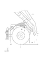
- the dump body 3 includes a pair of side plate portions 13 that extend along the traveling direction of the chassis 2, and a bottom surface portion 14 that is a bottom portion provided between the bottom edges of the side plate portions 13, A first inclined surface portion 15 rising upward from the rear end of the bottom surface portion 14; a second inclined surface portion 16 inclined downward from the upper end of the first inclined surface portion 15 toward the soil discharge side end portion P of the dump body 3; And a front surface portion 17 that rises from an end edge opposite to the edge at which the first inclined surface portion 15 of the bottom surface portion 14 rises.
- the protrusion part 18 which protrudes in a horizontal direction is provided in the upper end of the front part 17, and the protrusion part 18 protrudes in the length which covers the control apparatus 9 by planar view, and loads S, such as earth and sand, here (See FIG. 5) is not loaded.
- the pair of side plate portions 13 is formed of a steel plate-like body that is opposed to both sides of the chassis 2 in the vehicle width direction and extends in the traveling direction of the chassis 2.
- the bottom surface portion 14 is disposed at a substantially central portion of the chassis 2, and is formed of a steel plate-like body that extends horizontally in the traveling direction and the vehicle width direction of the chassis 2.
- the 1st inclined surface part 15 is comprised from the steel plate-shaped body which stands up diagonally upward from the rear end of the bottom face part 14, and when the bottom face part 14 is made into a horizontal surface, rising angle (theta) 1 is 12 degrees, for example.
- the second inclined surface portion 16 is inclined downward from the upper end of the first inclined surface portion 15 toward the soil discharge side end portion P of the dump body 3, and the angle ⁇ 2 inclined downward with respect to the horizontal plane is set to 20 °, for example. ing. Since the second inclined surface portion 16 is inclined downward, the load S such as earth and sand is not loaded.
- the front surface portion 17 as the third inclined surface portion is composed of a steel plate-like body that rises obliquely upward from the front end of the bottom surface portion 14, and when the bottom surface portion 14 is a horizontal surface, the rising angle ⁇ 3 of the front surface portion 17 is The rising angle ⁇ 1 of one inclined surface portion 15 is larger, for example, 40 °.
- the relationship between the dimension D1 of the front end 17 of the dump body 3 from the center in the front-rear direction of the chassis 2 and the dimension D2 of the upper end of the second inclined surface part 16 from the center in the front-rear direction of the chassis 2 is D1 ⁇ D2. ing.
- the center of gravity G of the mountain of the load S becomes approximately the center of the chassis 2.
- the ratio (H0 / D0) between the length dimension D0 of the load S in the front-rear direction and the load height dimension H0 is approximately 0.25.
- the height dimension H1 is 1800 mm to 2000 mm, which is substantially the same as the radius of the tire 5.
- the horizontal dimension D3 from the rear end of the tire 5 at the soil discharge side end portion P of the dump body 3 is 1000 mm to 1500 mm.
- the soil discharge side end portion P of the dump body 3 can be positioned closer to the ground at the time of soil removal.
- the load S can be made difficult to be scattered.
- the center of gravity G of the load S is the center in the front-rear direction of the chassis 2. It can be set in the vicinity, the load on the front and rear of the chassis 2 can be made uniform, and it is possible to prevent spillage or the like during the transportation.
- the height H1 of the soil discharge side end portion P of the dump body 3 is made equal to the radius of the tire 5, so that the soil is discharged in the lower half of the tire 5. Even if the load S is scattered, the load S can be reliably prevented from covering the tire 5.
- the rising angle ⁇ 3 of the front surface portion 17 larger than the rising angle ⁇ 1 of the first inclined surface portion 15, the distance until the load S on the front surface portion 17 side of the dump body 3 is discharged can be shortened. Therefore, the load flow can be further improved.
- the soil removal of the dump body 3 is performed. Since more loads can be loaded on the side, the load capacity of the dump body 3 is improved, and the load flow at the time of earthing is also improved. Since the loading ratio of the load S between the portion on the soil removal side and the portion on the opposite side from the center in the traveling direction of the chassis 2 can be adjusted, the gravity center position G of the load S is set near the center of the chassis 2 in the traveling direction. Can be set.
- the present invention is not limited to the above-described embodiments, and includes the following modifications.
- the dump truck 1 is an off-road dump truck that travels unattended.
- the present invention is not limited to this, and the present invention is applied to a dump truck having a cab described in the background art. Also good.
- it can be suitably applied to the invention described in Patent Document 1 (Japanese Patent Laid-Open No. Sho 62-50144), which is the prior art described in the background art.
- the rising angle ⁇ 1 of the first inclined surface portion 15, the angle ⁇ 2 of the inclination toward the lower side of the second inclined surface portion 16, and the rising angle ⁇ 3 of the front surface portion 17 are exemplified numerically, but are not limited thereto. Absent. What is necessary is just to set to an appropriate value according to the shape and dimension of a dump body. In addition, the specific structure, shape, and the like when implementing the present invention may be other structures as long as the object of the present invention can be achieved.
Landscapes
- Engineering & Computer Science (AREA)
- Transportation (AREA)
- Mechanical Engineering (AREA)
- Body Structure For Vehicles (AREA)
- Road Paving Machines (AREA)
Abstract
Description
このようなダンプトラックによれば、重心位置がホイールベースの略中央に設定されているため、油圧ショベル等の積込機械で土砂が積み込みやすくなり、荷こぼれを少なくすることができ、また、前輪、後輪に作用する荷重負荷を均等にすることができる、という効果がある。
また、ダンプボディを起こした際、排土側のダンプボディの端部が地面から高い位置となってしまうので、排土の際、土砂等が散らばり、タイヤ等に被ってしまうという課題がある。
また、第2傾斜面部を備えていることにより、排土時、ダンプボディの排土側端部をより地面に近い位置とすることができるため、排土時に土砂等の積載物を散らばりにくくすることができる。
本発明では、前記第1傾斜面部の上端から前記シャーシの前後方向の中心までの寸法が、前記第3傾斜面部の上端から前記シャーシの前後方向までの中心の寸法よりも大きいのが好ましい。
[1]ダンプトラック1の全体説明
図1から図4には、本発明の実施形態に係るダンプトラック1が示されている。図1は、斜視図であり、図2は、走行方向に直交する車幅方向から見た側面図、図3は、上視点から見た平面図、図4は、走行方向から見た側面図である。
ダンプトラック1は、シャーシ2およびダンプボディ3を備え、ダンプボディ3内に土砂等の積載物S(図5参照)を積載して前後双方向に前進走行し、図1における走行方向のX軸のマイナス方向を一方向として排土する。なお、前進走行とは、前後で区別がないため、双方向前進として同じ動きをすることできることをいう。
フレーム6は、シャーシ2の両側端部に走行方向に延出する一対のアッパーサイドメンバ6Aと、一対のロアーサイドメンバ6Bとを備える。上下に離間して配置されるアッパーサイドメンバ6Aおよびロアーサイドメンバ6Bは、先端および後端で複数のバーチカルメンバ6Cによって連結されている。また、車幅方向に配置される一対のアッパーサイドメンバ6A同士は、車幅方向に延びる複数のアッパークロスメンバによって連結され、一対のロアーサイドメンバ6B同士は、車幅方向に延びる複数のロアークロスメンバによって連結されている。すなわちフレーム6は、シャーシ2の走行方向から見て直方体状の骨組を有している。
エンジン7は、フレーム6のアッパーサイドメンバ6Aおよびロアーサイドメンバ6Bの間に設けられ、上部がアッパーサイドメンバ6Aから突出している。
また、エンジン7は、タイヤ4の後方側に設けられ、タイヤ4およびタイヤ5の回転中心で規定されるホイールベースW内に配置されており、ダンプトラック1の重心が、シャーシ2の略中央となっている。
制御装置9は、ダンプトラック1の走行を制御し、シャーシ2の排土側端部P(図5参照)に設けられる障害物検出センサや、エンジン7に設けられる温度センサ、タイヤ4、5に設けられた回転センサ等のセンサ情報に基づいて、ダンプトラック1の走行制御を行う。
ホイストシリンダ10は、制御装置9の後方に、車幅方向に2つ設けられ、その基部はフレーム6に回転可能に設けられ、先端はダンプボディ3の排土側端部Pとは反対側の端部下面に回転可能に設けられている。
ホイストシリンダ10は、図示を略したが、フレーム6内に設けられた油圧ポンプから作動油を受けて動作し、油圧ポンプは、エンジン7によって駆動される。
ダンプトラック用ダンプボディとしてのダンプボディ3は、図3に示されるように、平面視でシャーシ2の走行方向の全長および車幅方向の全幅を覆っており、ダンプボディ3の排土側端部Pは、シャーシ2の端部から延出している。ダンプボディ3は、図3に示されるように、平面視矩形状の箱状体として構成されている。なお、ダンプボディ3が矩形状で、シャーシ2も前後方向に同じ矩形状に作られているため、前後方向には区別されていない。このため、双方向に前進できる(便宜上前後として説明する。)。また、ダンプボディ3は、図示を略したが、バーチカルメンバ6Cの上端に設けられたボディマウント上に載置される。
ボディマウントは、フレーム6の上面に設けられ、ダンプボディ3の荷重をバーチカルメンバ6Cに伝達する。
ダンプボディ3は、フレーム6の排土側の走行方向の端部にヒンジ12を介して起伏可能に装着されている。ダンプボディ3は、前述したホイストシリンダ10が伸長することにより、フレーム6のヒンジ12を回転軸として起伏する。
底面部14は、図3および図5に示されるように、シャーシ2の略中央部に配置され、シャーシ2の走行方向および車幅方向に水平に延びる鋼製板状体から構成されている。
第1傾斜面部15は、底面部14の後端から斜め上方に立ち上がる鋼製板状体から構成され、底面部14を水平面としたときに、立ち上がり角度θ1は、例えば12°とされている。
第3傾斜面部としての前面部17は、底面部14の前端から斜め上方に立ち上がる鋼製板状体から構成され、底面部14を水平面としたときに、前面部17の立ち上がり角度θ3は、第1傾斜面部15の立ち上がり角度θ1よりも大きくなっていて、例えば40°とされている。
これにより、ダンプボディ3に土砂等の積載物Sを積み込むと、積載物Sの山の重心位置Gがシャーシ2の略中央になる。また、積載物Sをダンプボディ3に積み込んだ際、積載物Sの前後方向の長さ寸法D0と、積載高さ寸法H0の比(H0/D0)は、略0.25となる。
このような本実施形態によれば、以下のような効果がある。
ダンプボディ3が、第2傾斜面部16を備えていることにより、排土時、ダンプボディ3の排土側端部Pをより地面に近い位置とすることができるため、排土時に土砂等の積載物Sを散らばりにくくすることができる。
また、積載物Sをシャーシ2の前後方向中心から排土側の部分と、反対側の部分での積載比率を調整することができるので、積載物Sの重心位置Gをシャーシ2の前後方向中心近傍に設定することができ、シャーシ2の前後の負担を均等にして、搬送中に荷こぼれ等が生じることを防止できる。
前面部17の立ち上がり角度θ3を、第1傾斜面部15の立ち上がり角度θ1よりも大きくすることにより、ダンプボディ3の前面部17側の積載物Sを排土するまでの距離を短くすることができるので、荷流れを一層良好にすることができる。
積載物Sをシャーシ2の走行方向中心から排土側の部分と、反対側の部分での積載比率を調整することができるので、積載物Sの重心位置Gをシャーシ2の走行方向中心近傍に設定することができる。
本発明は、前述した実施形態に限定されるものではなく、以下のような変形も含まれる。
前述した実施形態では、ダンプトラック1は、無人で走行するオフロードダンプトラックであったが、本発明はこれに限らず、背景技術で述べたキャブを備えたダンプトラックに本発明を適用してもよい。
特に、背景技術で説明した先行技術である特許文献1(特開昭62-50144号公報)に記載された発明には、好適に適用することができる。
その他、本発明の実施の際の具体的な構造および形状等は、本発明の目的を達成できる範囲で他の構造等としてもよい。
Claims (4)
- 排土側に底部から上方に立ち上がる第1傾斜面部と、前記第1傾斜面部の上端から排土側端部に向かって下方に傾斜した第2傾斜面部とを備えていることを特徴とするダンプトラック用ダンプボディ。
- 前後双方向に前進走行し、一方向に排土するダンプトラックであって、
ホイールベース内にエンジンが設けられたシャーシと、
前記シャーシの走行方向の全長および車幅方向の全幅にわたって前記シャーシの上部を覆い、前記シャーシの排土側でヒンジを介して起伏可能に支持されたダンプボディと、を備え、
前記ダンプボディは、排土側に前記ダンプボディの底部から上方に立ち上がる第1傾斜面部と、前記第1傾斜面部の上端から排土側端部に向かって下方に傾斜する第2傾斜面部とを備え、
前記ダンプボディを起こしたときに、前記ダンプボディの排土側端部の高さが、前記シャーシのタイヤの半径に等しいことを特徴とするダンプトラック。 - 請求項2に記載のダンプトラックにおいて、
前記ダンプボディは、前記ダンプボディの前記第1傾斜面部とは反対側に前記ダンプボディの底部から上方に立ち上がる第3傾斜面部を備え、
第3傾斜面部の水平面からの立ち上がり角度は、前記第1傾斜面部の水平面からの立ち上がり角度よりも大きいことを特徴とするダンプトラック。 - 請求項3に記載のダンプトラックにおいて、
前記第1傾斜面部の上端から前記シャーシの前後方向の中心までの寸法が、前記第3傾斜面部の上端から前記シャーシの前後方向までの中心の寸法よりも大きいことを特徴とするダンプトラック。
Priority Applications (5)
| Application Number | Priority Date | Filing Date | Title |
|---|---|---|---|
| CN201680045551.7A CN107921901B (zh) | 2016-03-16 | 2016-03-16 | 自卸车用料斗及自卸车 |
| US15/750,861 US10632890B2 (en) | 2016-03-16 | 2016-03-16 | Dump truck dump body, and dump truck |
| PCT/JP2016/058412 WO2017158778A1 (ja) | 2016-03-16 | 2016-03-16 | ダンプトラック用ダンプボディおよびダンプトラック |
| JP2018505153A JP6613363B2 (ja) | 2016-03-16 | 2016-03-16 | ダンプトラック用ダンプボディおよびダンプトラック |
| CA2994628A CA2994628C (en) | 2016-03-16 | 2016-03-16 | Dump truck dump body, and dump truck |
Applications Claiming Priority (1)
| Application Number | Priority Date | Filing Date | Title |
|---|---|---|---|
| PCT/JP2016/058412 WO2017158778A1 (ja) | 2016-03-16 | 2016-03-16 | ダンプトラック用ダンプボディおよびダンプトラック |
Publications (1)
| Publication Number | Publication Date |
|---|---|
| WO2017158778A1 true WO2017158778A1 (ja) | 2017-09-21 |
Family
ID=59851701
Family Applications (1)
| Application Number | Title | Priority Date | Filing Date |
|---|---|---|---|
| PCT/JP2016/058412 Ceased WO2017158778A1 (ja) | 2016-03-16 | 2016-03-16 | ダンプトラック用ダンプボディおよびダンプトラック |
Country Status (5)
| Country | Link |
|---|---|
| US (1) | US10632890B2 (ja) |
| JP (1) | JP6613363B2 (ja) |
| CN (1) | CN107921901B (ja) |
| CA (1) | CA2994628C (ja) |
| WO (1) | WO2017158778A1 (ja) |
Families Citing this family (5)
| Publication number | Priority date | Publication date | Assignee | Title |
|---|---|---|---|---|
| USD773958S1 (en) * | 2015-03-24 | 2016-12-13 | Palmer Trucks, Inc. | Storage tank for dump body |
| US20180327982A1 (en) * | 2017-05-09 | 2018-11-15 | Somero Enterprises, Inc. | Concrete screeding system with rotatable screed head |
| EP3953213B1 (en) | 2019-04-12 | 2023-06-07 | Volvo Truck Corporation | A method for controlling a lifting and lowering sequence of a vehicle and a vehicle comprising a chassis structure and a load carrying body |
| CN112026620A (zh) * | 2020-08-17 | 2020-12-04 | 东莞理工学院 | 一种具有感应功能的无人驾驶运矿车 |
| CN111976847B (zh) * | 2020-08-27 | 2022-08-30 | 徐州徐工矿业机械有限公司 | 一种用于矿用自卸车货厢的侧板结构 |
Citations (5)
| Publication number | Priority date | Publication date | Assignee | Title |
|---|---|---|---|---|
| JPS54132114U (ja) * | 1978-03-07 | 1979-09-13 | ||
| JPH11502481A (ja) * | 1995-03-31 | 1999-03-02 | ビーエイチピー コール プロプライアタリー リミティド | 大型ダンプトラックサスペンション |
| USD471920S1 (en) * | 2001-03-05 | 2003-03-18 | Arthur William Chaseling | Vehicle |
| US20120153705A1 (en) * | 2009-12-18 | 2012-06-21 | Western Technology Services International, Inc. | Truck Body |
| US20150307012A1 (en) * | 2012-12-04 | 2015-10-29 | Aveling Barford (Holdings) Limited | Vehicle or Trailer with Dropping Floor |
Family Cites Families (9)
| Publication number | Priority date | Publication date | Assignee | Title |
|---|---|---|---|---|
| US3578375A (en) * | 1969-02-24 | 1971-05-11 | Johnson Rubber Co | Cushioning liner for vehicles or the like |
| IT1108349B (it) | 1978-04-04 | 1985-12-09 | Cselt Centro Studi Lab Telecom | Procedimento e dispositivo di sincronizzazione per trasmissione numeriche via satellite |
| JPS6259144A (ja) | 1985-09-06 | 1987-03-14 | Komatsu Ltd | ダンプトラツク |
| CN1041729A (zh) | 1988-10-13 | 1990-05-02 | 贝尔恩德·奥斯特迈耶 | 侧面倾卸装置支撑系统 |
| DE9210667U1 (de) * | 1992-08-10 | 1992-10-08 | Menshen Containerservice GmbH & Co. KG, 5970 Plettenberg | Behälter |
| AUPR902901A0 (en) * | 2001-11-23 | 2001-12-20 | Keech Castings Australia Pty Limited | A pivotal tail extension |
| US7901009B2 (en) | 2006-09-14 | 2011-03-08 | Hagenbuch Leroy G | Severe application off-highway truck body |
| PE20130766A1 (es) | 2011-10-12 | 2013-06-26 | Sepulveda Richard Cotal | Tolva para el transporte de mineral o aridos, posee en la zona de union entre el frontal y el piso y en la zona de union entre los laterales y el piso piezas plegables o cilindradas que le dan curvatura a dicha union, tiene plegados en el frontal y en la visera para evitar las vigas en esa zona disminuyendo el peso de la tolva |
| US20140283422A1 (en) | 2013-03-19 | 2014-09-25 | Alain Cloutier | Attachment bracket for use with heavy machinery and bracket members |
-
2016
- 2016-03-16 WO PCT/JP2016/058412 patent/WO2017158778A1/ja not_active Ceased
- 2016-03-16 JP JP2018505153A patent/JP6613363B2/ja active Active
- 2016-03-16 CN CN201680045551.7A patent/CN107921901B/zh not_active Expired - Fee Related
- 2016-03-16 US US15/750,861 patent/US10632890B2/en active Active
- 2016-03-16 CA CA2994628A patent/CA2994628C/en active Active
Patent Citations (5)
| Publication number | Priority date | Publication date | Assignee | Title |
|---|---|---|---|---|
| JPS54132114U (ja) * | 1978-03-07 | 1979-09-13 | ||
| JPH11502481A (ja) * | 1995-03-31 | 1999-03-02 | ビーエイチピー コール プロプライアタリー リミティド | 大型ダンプトラックサスペンション |
| USD471920S1 (en) * | 2001-03-05 | 2003-03-18 | Arthur William Chaseling | Vehicle |
| US20120153705A1 (en) * | 2009-12-18 | 2012-06-21 | Western Technology Services International, Inc. | Truck Body |
| US20150307012A1 (en) * | 2012-12-04 | 2015-10-29 | Aveling Barford (Holdings) Limited | Vehicle or Trailer with Dropping Floor |
Also Published As
| Publication number | Publication date |
|---|---|
| US10632890B2 (en) | 2020-04-28 |
| CA2994628C (en) | 2019-08-20 |
| CN107921901B (zh) | 2021-06-08 |
| US20180229639A1 (en) | 2018-08-16 |
| CA2994628A1 (en) | 2017-09-21 |
| JP6613363B2 (ja) | 2019-11-27 |
| CN107921901A (zh) | 2018-04-17 |
| JPWO2017158778A1 (ja) | 2019-01-17 |
Similar Documents
| Publication | Publication Date | Title |
|---|---|---|
| JP6613363B2 (ja) | ダンプトラック用ダンプボディおよびダンプトラック | |
| CN105339557B (zh) | 铲斗及具备其的作业车辆 | |
| US10550545B2 (en) | Work vehicle | |
| US9556588B2 (en) | Floor member and working machine | |
| CN107921902A (zh) | 自卸车辆 | |
| EP2987917B1 (en) | Bucket, and work vehicle provided with same | |
| US9366006B2 (en) | Bucket for work vehicle, and work vehicle equipped with bucket with left and right boom attachment portions | |
| JP5941418B2 (ja) | 作業車両 | |
| US12037768B2 (en) | Work vehicle | |
| EP4566920A1 (en) | Dump truck | |
| JP5923666B2 (ja) | ダンプトラックの荷台構造 | |
| US20240198886A1 (en) | A Body for a Machine Comprising a Body Cavity for Receiving Material | |
| US20240279911A1 (en) | Construction machine | |
| JP2010013084A (ja) | ダンプトラックのリヤバンパ | |
| JPH11343637A (ja) | 旋回式クローラキャリア | |
| EP3546661B1 (en) | Wheel loader | |
| KR20150072641A (ko) | 건설기계 | |
| JP2025144314A (ja) | 作業車両用作動油タンク及び作業車両 | |
| JP2012111411A (ja) | 運搬車両 | |
| JPH06146339A (ja) | 溝に土砂を充填する装置 | |
| JP2002211448A (ja) | 動力運搬車 |
Legal Events
| Date | Code | Title | Description |
|---|---|---|---|
| ENP | Entry into the national phase |
Ref document number: 2018505153 Country of ref document: JP Kind code of ref document: A |
|
| ENP | Entry into the national phase |
Ref document number: 2994628 Country of ref document: CA |
|
| WWE | Wipo information: entry into national phase |
Ref document number: 15750861 Country of ref document: US |
|
| NENP | Non-entry into the national phase |
Ref country code: DE |
|
| 121 | Ep: the epo has been informed by wipo that ep was designated in this application |
Ref document number: 16894396 Country of ref document: EP Kind code of ref document: A1 |
|
| 122 | Ep: pct application non-entry in european phase |
Ref document number: 16894396 Country of ref document: EP Kind code of ref document: A1 |