WO2017155069A1 - Seat structure - Google Patents
Seat structure Download PDFInfo
- Publication number
- WO2017155069A1 WO2017155069A1 PCT/JP2017/009608 JP2017009608W WO2017155069A1 WO 2017155069 A1 WO2017155069 A1 WO 2017155069A1 JP 2017009608 W JP2017009608 W JP 2017009608W WO 2017155069 A1 WO2017155069 A1 WO 2017155069A1
- Authority
- WO
- WIPO (PCT)
- Prior art keywords
- seat
- backrest
- support
- angle
- seated person
- Prior art date
Links
Images


Classifications
-
- A—HUMAN NECESSITIES
- A47—FURNITURE; DOMESTIC ARTICLES OR APPLIANCES; COFFEE MILLS; SPICE MILLS; SUCTION CLEANERS IN GENERAL
- A47C—CHAIRS; SOFAS; BEDS
- A47C7/00—Parts, details, or accessories of chairs or stools
- A47C7/50—Supports for the feet or the legs coupled to fixed parts of the chair
- A47C7/506—Supports for the feet or the legs coupled to fixed parts of the chair of adjustable type
- A47C7/5066—Supports for the feet or the legs coupled to fixed parts of the chair of adjustable type by rotation
- A47C7/5068—Supports for the feet or the legs coupled to fixed parts of the chair of adjustable type by rotation actuated by linkages
-
- B—PERFORMING OPERATIONS; TRANSPORTING
- B60—VEHICLES IN GENERAL
- B60N—SEATS SPECIALLY ADAPTED FOR VEHICLES; VEHICLE PASSENGER ACCOMMODATION NOT OTHERWISE PROVIDED FOR
- B60N2/00—Seats specially adapted for vehicles; Arrangement or mounting of seats in vehicles
- B60N2/02—Seats specially adapted for vehicles; Arrangement or mounting of seats in vehicles the seat or part thereof being movable, e.g. adjustable
-
- A—HUMAN NECESSITIES
- A47—FURNITURE; DOMESTIC ARTICLES OR APPLIANCES; COFFEE MILLS; SPICE MILLS; SUCTION CLEANERS IN GENERAL
- A47C—CHAIRS; SOFAS; BEDS
- A47C1/00—Chairs adapted for special purposes
- A47C1/02—Reclining or easy chairs
- A47C1/031—Reclining or easy chairs having coupled concurrently adjustable supporting parts
- A47C1/036—Reclining or easy chairs having coupled concurrently adjustable supporting parts the parts including a head-rest
- A47C1/037—Reclining or easy chairs having coupled concurrently adjustable supporting parts the parts including a head-rest in combination with a leg-rest or foot-rest
-
- A—HUMAN NECESSITIES
- A47—FURNITURE; DOMESTIC ARTICLES OR APPLIANCES; COFFEE MILLS; SPICE MILLS; SUCTION CLEANERS IN GENERAL
- A47C—CHAIRS; SOFAS; BEDS
- A47C7/00—Parts, details, or accessories of chairs or stools
- A47C7/36—Support for the head or the back
- A47C7/38—Support for the head or the back for the head
-
- B—PERFORMING OPERATIONS; TRANSPORTING
- B60—VEHICLES IN GENERAL
- B60N—SEATS SPECIALLY ADAPTED FOR VEHICLES; VEHICLE PASSENGER ACCOMMODATION NOT OTHERWISE PROVIDED FOR
- B60N2/00—Seats specially adapted for vehicles; Arrangement or mounting of seats in vehicles
- B60N2/02—Seats specially adapted for vehicles; Arrangement or mounting of seats in vehicles the seat or part thereof being movable, e.g. adjustable
- B60N2/04—Seats specially adapted for vehicles; Arrangement or mounting of seats in vehicles the seat or part thereof being movable, e.g. adjustable the whole seat being movable
- B60N2/10—Seats specially adapted for vehicles; Arrangement or mounting of seats in vehicles the seat or part thereof being movable, e.g. adjustable the whole seat being movable tiltable
-
- B—PERFORMING OPERATIONS; TRANSPORTING
- B60—VEHICLES IN GENERAL
- B60N—SEATS SPECIALLY ADAPTED FOR VEHICLES; VEHICLE PASSENGER ACCOMMODATION NOT OTHERWISE PROVIDED FOR
- B60N2/00—Seats specially adapted for vehicles; Arrangement or mounting of seats in vehicles
- B60N2/02—Seats specially adapted for vehicles; Arrangement or mounting of seats in vehicles the seat or part thereof being movable, e.g. adjustable
- B60N2/22—Seats specially adapted for vehicles; Arrangement or mounting of seats in vehicles the seat or part thereof being movable, e.g. adjustable the back-rest being adjustable
-
- B—PERFORMING OPERATIONS; TRANSPORTING
- B60—VEHICLES IN GENERAL
- B60N—SEATS SPECIALLY ADAPTED FOR VEHICLES; VEHICLE PASSENGER ACCOMMODATION NOT OTHERWISE PROVIDED FOR
- B60N2/00—Seats specially adapted for vehicles; Arrangement or mounting of seats in vehicles
- B60N2/80—Head-rests
-
- B—PERFORMING OPERATIONS; TRANSPORTING
- B64—AIRCRAFT; AVIATION; COSMONAUTICS
- B64D—EQUIPMENT FOR FITTING IN OR TO AIRCRAFT; FLIGHT SUITS; PARACHUTES; ARRANGEMENTS OR MOUNTING OF POWER PLANTS OR PROPULSION TRANSMISSIONS IN AIRCRAFT
- B64D11/00—Passenger or crew accommodation; Flight-deck installations not otherwise provided for
- B64D11/06—Arrangements of seats, or adaptations or details specially adapted for aircraft seats
- B64D11/0606—Arrangements of seats, or adaptations or details specially adapted for aircraft seats with privacy shells, screens, separators or the like
-
- B—PERFORMING OPERATIONS; TRANSPORTING
- B64—AIRCRAFT; AVIATION; COSMONAUTICS
- B64D—EQUIPMENT FOR FITTING IN OR TO AIRCRAFT; FLIGHT SUITS; PARACHUTES; ARRANGEMENTS OR MOUNTING OF POWER PLANTS OR PROPULSION TRANSMISSIONS IN AIRCRAFT
- B64D11/00—Passenger or crew accommodation; Flight-deck installations not otherwise provided for
- B64D11/06—Arrangements of seats, or adaptations or details specially adapted for aircraft seats
- B64D11/0639—Arrangements of seats, or adaptations or details specially adapted for aircraft seats with features for adjustment or converting of seats
- B64D11/064—Adjustable inclination or position of seats
-
- B—PERFORMING OPERATIONS; TRANSPORTING
- B64—AIRCRAFT; AVIATION; COSMONAUTICS
- B64D—EQUIPMENT FOR FITTING IN OR TO AIRCRAFT; FLIGHT SUITS; PARACHUTES; ARRANGEMENTS OR MOUNTING OF POWER PLANTS OR PROPULSION TRANSMISSIONS IN AIRCRAFT
- B64D11/00—Passenger or crew accommodation; Flight-deck installations not otherwise provided for
- B64D11/06—Arrangements of seats, or adaptations or details specially adapted for aircraft seats
- B64D11/0639—Arrangements of seats, or adaptations or details specially adapted for aircraft seats with features for adjustment or converting of seats
- B64D11/0642—Adjustable headrests
-
- B—PERFORMING OPERATIONS; TRANSPORTING
- B64—AIRCRAFT; AVIATION; COSMONAUTICS
- B64D—EQUIPMENT FOR FITTING IN OR TO AIRCRAFT; FLIGHT SUITS; PARACHUTES; ARRANGEMENTS OR MOUNTING OF POWER PLANTS OR PROPULSION TRANSMISSIONS IN AIRCRAFT
- B64D11/00—Passenger or crew accommodation; Flight-deck installations not otherwise provided for
- B64D11/06—Arrangements of seats, or adaptations or details specially adapted for aircraft seats
- B64D11/0639—Arrangements of seats, or adaptations or details specially adapted for aircraft seats with features for adjustment or converting of seats
- B64D11/0643—Adjustable foot or leg rests
-
- B—PERFORMING OPERATIONS; TRANSPORTING
- B63—SHIPS OR OTHER WATERBORNE VESSELS; RELATED EQUIPMENT
- B63B—SHIPS OR OTHER WATERBORNE VESSELS; EQUIPMENT FOR SHIPPING
- B63B29/00—Accommodation for crew or passengers not otherwise provided for
- B63B29/02—Cabins or other living spaces; Construction or arrangement thereof
- B63B29/04—Furniture peculiar to vessels
- B63B2029/043—Seats; Arrangements thereof on vessels
Definitions
- the present invention relates to a seat structure, and more particularly to a seat structure suitable for vehicles such as buses, vehicles, airplanes, trains, and ships.
- Patent Document 1 includes a seat, a backrest, a headrest and a legrest (in this specification, “legrest” includes what is called an ottoman, a footrest, etc., and supports only the lower leg. Including the type that supports both the lower leg and the foot), and the seat, backrest, and legrest operate in conjunction with each other to provide posture changing functions such as sitting posture, nap posture, resting posture, etc.
- legrest includes what is called an ottoman, a footrest, etc., and supports only the lower leg.
- the seat, backrest, and legrest operate in conjunction with each other to provide posture changing functions such as sitting posture, nap posture, resting posture, etc.
- chairs that can be used as automobile seats, office chairs, etc.
- Patent Documents 2 and 3 have the following structures. That is, it has a leg rest in addition to a seat, a backrest, and a headrest, and can be reclined until it becomes almost full flat, and can rest in a state close to a bed.
- Patent Document 1 The chair disclosed in Patent Document 1 is suitable for taking a rest and a nap because the seat, the backrest, the headrest and the legrest operate in conjunction with each other. And In particular, when applied to the rear seat, the foot space is narrow, and it is necessary to recline after moving the entire rear seat backward.For example, when applied to an automobile, a relatively large van type vehicle, etc. There is a tendency to be limited to a wide interior space. Therefore, a seat that can cope with various posture changes such as a sitting posture, a resting posture, and a nap posture is desired even in a more limited installation space.
- the present invention has been made in view of the above, and can cope with various posture changes of a seated person in a limited installation space like a vehicle such as an automobile such as a bus, a train, and an aircraft, and is more comfortable and fatigued. It is another object of the present invention to provide a seat structure that can provide a comfortable sitting comfort and can be used not only for vehicles but also for various applications.
- the seat structure of the present invention is A seat structure including a seat and a backrest that can be reclined with respect to the seat, In the upright position where the torso angle is equal to or smaller than a predetermined angle, the seat and the backrest are in a normal support form in which the support form is constant, and both are seated by the seat part and the backrest in the normal support form.
- the seat portion In the relaxed position where the backrest is reclined and the torso angle is equal to or greater than a predetermined angle, the seat portion is in a variable support configuration in which the support configuration varies following the movement of the center of gravity of the seated person, and the seat portion in the variable support configuration And a seated person is supported by the said backrest of a normal support form, It is characterized by the above-mentioned.
- a leg rest provided so as to be able to protrude forward from below the seat portion; In the relaxed position, it is preferable that a seated person is supported by the legrest protruding forward, the seat portion in the variable support form, and the backrest in the normal support form.
- the legrest is preferably provided so as to follow the movement of the lower leg portion of the seated person.
- the seat is In the relaxed position, When a seated person applies a load in the vicinity of the sciatic tuberculosis support part of the seat part, it rotates around a site in front of the sciatic tuberculosis support part and is displaced so that the rear edge part is positioned below the front edge part, When a seat occupant applies a load near the front edge of the seat, the seat rotates so as to be centered on the rear part of the ischial tubercle support and is displaced so that the front edge is positioned below the rear edge. do it, It is preferable that the variable support configuration follows the movement of the center of gravity of the seated person.
- the relaxed position is defined as a rest position where an angle ⁇ between a line connecting the hip point and the knee center and the torso line is in a range of a predetermined angle to 180 degrees, and between the rest position and the upright position.
- the seat portion is variable on the basis of a support form in which the rear edge portion is positioned below the front edge portion
- the rest position it is preferable that the seat portion is configured to vary based on a support form in which the front edge portion is positioned below the rear edge portion.
- the reclining operation of the backrest is set in a range of up to 70 degrees in a torso angle, and in the relaxed position, a portion corresponding to the upper body of the seated person is a supporting fulcrum during the backrest. preferable.
- two axes that are orthogonal to each other are formed so that one is long and the other is short, and is rotatably supported by a mounting portion around the backrest. It is preferable that one end along the head serves as a head support, and has a headrest that rotates by being pushed by the head in the relaxed position, and one end along the short axis direction serves as the head support.
- the mounting portion around the backrest is a vehicle body portion or a frame independent of the backrest, and a rotating shaft connected to the body portion or the frame independent of the backrest is a member along the long direction of the axis. It is preferable to support the end.
- the angle ⁇ formed by the line connecting the hip point and the knee center and the torso line is 120 degrees or less
- the angle ⁇ in the rest position is in the range of 140 to 180 degrees
- the intermediate position The angle ⁇ is preferably in the range of 110 to 150 degrees.
- support form the position of the seat itself or the backrest itself (hereinafter referred to as “support form”) when supporting the seated person, such as the position and inclination angle of the seat and backrest, is referred to as “support form” in this specification. Different positions and relaxed positions.
- the seated person in the upright position where the torso angle is equal to or smaller than the predetermined angle, the seated person is supported in a normal support configuration in which the posture of the seat portion itself and the posture of the backrest itself are both constant, while the backrest is reclined so that the torso angle
- the backrest stably supports the upper body of the seated person in a normal support form in which the posture of the seat itself is constant, but the seat portion has a configuration in which the posture of the seat portion is not constant but variable ( Variable support form).
- the posture of the seat itself changes.
- the rear edge is displaced downward from the front edge, a load is applied from the thigh to the vicinity of the knee, and in a posture where the center of gravity moves forward, the front edge is It is displaced so as to be positioned below the rear edge.
- the upper body particularly near the scapula
- the lower leg is supported by the legrest.
- the angle ⁇ formed by the line connecting the hip point and the knee center and the torso line becomes closer to 180 degrees, which is suitable for nap etc. It becomes easy to take a supine posture (sleeping posture), and when the seated person takes a posture in which the rear edge portion is displaced downward, this angle ⁇ is slightly narrowed, so that reading or video watching can be performed while relaxing.
- the posture is suitable for performing. In the upright position, both the seat portion and the backrest are normally supported, so that the sitting posture is stable, and a posture suitable for light work or meals can be easily taken.
- the seated person can be supported following the various posture changes from the upright position to the relaxed position (intermediate position and resting position), and the seating comfort can be reduced with less fatigue. Can be provided.
- the relaxed position when the angle ⁇ between the hip point and the line connecting the center of the knee and the torso line is a resting position closer to 180 degrees, the front edge of the seat is displaced downward, so the backrest A posture close to the supine posture can be taken without reclining until it becomes horizontal. Therefore, the space between the front seat and the rear seat can be made narrower than before by providing the lower portion of the seat portion of the front seat as a space for the foot of the rear seat occupant to enter. For this reason, the present invention is preferably applied to passenger seats of buses or rear seats of ordinary automobiles, and is also suitable for passenger seats of trains, airplanes and the like.
- FIG. 1A to 1C are perspective views showing the appearance of a seat structure according to an embodiment of the present invention, in which FIG. 1A shows an upright position, and FIG. 1B shows an intermediate position in a relaxed position.
- (C) is a perspective view which shows the rest position in a relaxing position.
- FIG. 2A is a side view showing a schematic configuration of the seat structure according to the embodiment in the upright position
- FIG. 2B is a seat structure according to the embodiment in the intermediate position in the relax position
- FIG. 2C is a side view showing the schematic configuration of the seat structure according to the embodiment in the rest position during the relaxed position.
- FIG. 3 is a schematic diagram showing each position of the seat structure and the posture of the seated person supported thereby.
- FIGS. 4 is a diagram for explaining an example of a mode in which a space between the front seat and the rear seat is narrowed.
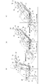
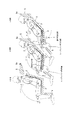
- FIGS. 5A to 5C are diagrams for explaining an example of the operation mechanism of the leg rest.
- FIGS. 6A to 6C are diagrams for explaining an example of the operation mechanism of the leg rest.
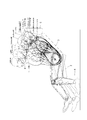
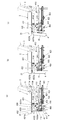
- FIGS. 7A to 7C are diagrams for explaining an example of an operation mechanism in which the legrest, the backrest, and the headrest are interlocked.
- FIGS. 8A to 8C are diagrams for explaining an example of an operation mechanism in which the legrest, the backrest, and the headrest are interlocked.
- the seat structure 1 of the present embodiment includes a seat portion 2, a backrest 3, a legrest 4, a headrest 5, and the like. Further, a seat partition frame 6 is provided independently of the backrest 3 so as to surround the back from the left and right of the backrest 3, and is used as an advanced grade seat in a bus or the like.
- the seat portion 2 is supported by a pair of leg portions 7 and 7 protruding forward from the left and right of the seat partition frame 6 and provided at a predetermined height from the installation surface.
- the seat 2 is supported so as to be rotatable about a first seat rotation fulcrum 2a set forward of the center in the front-rear direction (see FIG. 2B).
- the seat portion 2 is provided so as to be rotatable about a second seat portion rotation fulcrum 2b provided at the rear portion between the leg portions 7 and 7 (see FIG. 2C). Therefore, when the seat portion 2 rotates about the first seat portion rotation fulcrum 2a, the rear edge portion 22 is displaced below the front edge portion 21 (FIGS. 1B and 2B). )), And when rotating about the second seat rotation fulcrum 2b, the front edge 21 is configured to be displaced below the rear edge 22 (FIGS. 1C and 2). (See (c)).
- the backrest 3 is provided such that it can recline back and forth around the rotation fulcrum 3a for the backrest provided at the rear part of the legs 7 and 7 located at the lower part of the backrest 3 (see FIG. 2B).
- the reclining angle is set so that the torso angle is preferably in the range of up to 70 degrees, more preferably in the range of 0 to 60 degrees.
- the seat partition frame 6 that surrounds the backrest 3 has the back plate 61 within a range of up to about 70 degrees rearward with respect to the perpendicular in the example of this embodiment so that the maximum reclining angle of the backrest 3 can be allowed. What is necessary is just to provide.
- the back plate 61 has an external shape in which the upper portion protrudes rearward from the lower portion, and therefore, a footrest space for the rear seat occupant is formed below the back plate 61. .
- the legrest 4 is attached to the seat 2. Specifically, as shown in FIG. 1, the legrest 4 has a surface that is, for example, a substantially rectangular lower leg support surface 41, and an upright position (FIG. 1A and FIG. 2A described later). In the state of), the lower leg support surface 41 is stored below the front edge 21 of the seat 2 with the front side facing forward. In a relaxed position (the state shown in FIGS. 1B and 1C and FIGS. 2B and 2C), which will be described later, it projects forward from the accommodation position and is displaced so that the lower leg support surface 41 faces upward.
- a relaxed position the state shown in FIGS. 1B and 1C and FIGS. 2B and 2C
- the legrest 4 protrudes forward, maintains the state in which the inclination angle and the vertical position of the lower end support surface 41 are constant, and does not follow the movement of the lower leg portion of the seated person.
- a form that supports the lower leg (the legrest 4 can be configured to support such a form as a “normal support form”), or a variable support that supports the lower leg while displacing following the movement of the lower leg. It can also be in the form.
- the leg rest 4 as a whole supports the leg rest 4 in accordance with the change in the position of the center of gravity of the lower leg due to the movement of the lower leg and the change in the load applied to the leg rest 4.
- the front edge of the lower leg support surface 41 centered on the rear edge of the lower leg support surface 41. It is possible to adopt a configuration in which the part is displaced in the direction of rotating up and down.
- the legrest 4 may move forward independently, but may protrude forward in conjunction with the reclining operation of the backrest 3.
- the link mechanism that extends the legrest 4 can be connected to a motor or the like, and in the latter case, the backrest 3 is reclined to be displaced from the upright position to the relaxed position. And can be provided so as to protrude forward with the movement.
- various known mechanisms can be used. For example, when the mechanism disclosed in Patent Document 1, that is, when the backrest 3 tilts backward, the connecting member rotates in the same direction. A mechanism in which a pantograph type link mechanism supported by the connecting member extends forward can be employed. If the legrest 4 is supported by this link mechanism, the legrest 4 can be projected forward in conjunction with the reclining operation of the backrest 3. A specific example of the legrest 4 will be described later.
- FIGS. 2A to 2C are side views showing the upright position and the relax position defined in the present invention.
- the seat 2 and the backrest 3 are in the positions shown in FIG. 2A, and the seated person is supported so that the torso angle ⁇ is equal to or less than a predetermined angle.
- the positional relationship between the seat 2 and the backrest 3 in the upright position is preferably such that the angle ⁇ between the line A connecting the hip point HP and the knee center KP and the torso line B is 120 degrees or less. More preferably, the angle ⁇ is in the range of 90 to 120 degrees. In this case, the torso angle ⁇ is preferably in the range of 0 to 25 degrees.
- the hip angle ⁇ formed by the horizontal plane and the line A is preferably in the range of 0 to 10 degrees.
- the angle ⁇ between the line A and the torso line B is 104 degrees
- the torso angle ⁇ is 18 degrees
- the hip angle ⁇ is 4 degrees.
- the seat 2 and the backrest 3 support the seated person in a normal support form at a position that satisfies such an angle condition. That is, the seat portion 2 and the backrest 3 itself are moved in the vertical direction and the support angle does not change, and the seat portion 2 and the backrest 3 themselves are seated in the normal support form in which the posture is kept constant. I support you.
- the cushion material used for each of the seat 2 and the backrest 3 is subjected to a load or a center of gravity in the state where the above angle condition is satisfied.
- the cushioning material is compressed and deformed, submerged, or changed. Therefore, in the upright position, the seated person can stably perform light work and eat.
- the torso angle ⁇ is usually about 3 degrees, and the shoulder or the shoulder blade is slightly backrested.
- the seat 2 and the backrest 3 are normally supported so that they do not easily slide on the bottom, can be easily maintained, and are stable.
- FIGS. 2B and 2C show a state where the backrest 3 is in a relaxed position.
- FIG. 2 (c) shows a rest position where the posture of the seated person is closest to the supine posture
- FIG. 2 (b) is closer to the upright position than the rest position in the relaxed position. Indicates an intermediate position.
- the angle ⁇ formed by the line A connecting the hip point HP and the knee center KP and the torso line B is not less than a predetermined angle and not more than 180 degrees, preferably in the range of 140 to 180 degrees. is there.
- the torso angle ⁇ is preferably in the range of 30 to 70 degrees
- the hip angle ⁇ formed by the horizontal plane and the line A is preferably in the range of ⁇ 3 to ⁇ 30 degrees.
- the intermediate position in FIG. 2B is an intermediate position between the upright position and the rest position, and an angle ⁇ formed by the line A connecting the hip point HP and the knee center KP and the torso line B is preferable. Is in the range of 110 to 150 degrees.
- the torso angle ⁇ is preferably in the range of 30 to 70 degrees
- the hip angle ⁇ formed by the horizontal plane and the line A is preferably in the range of 3 to 20 degrees.
- the legrest 4 protrudes forward to support the lower leg of the seated person.
- the legrest 4 is at the intermediate position in FIG. 2 (b) with respect to the seat portion 2 at the horizontal position, and at the rest position in FIG. 2 (c), at the rest position in FIG.
- it is preferably set so as to protrude at an angle of 120 degrees or more, preferably 120 to 180 degrees.
- both are set to 150 degrees, but as a result, the lower leg support surface 41 becomes an inclined surface that is lowered forward and is naturally supported without applying excessive force to the lower leg. it can.
- the load shared by the backrest 3 from the vicinity of the upper scapula away from the vicinity of the sciatic nodule to the shoulder (upper body) and leg is higher than the upright position of FIG. 2A, and the shared load of the seat portion 2 is relatively small. Since the shared load of the seat portion 2 becomes relatively small, if the seat portion 2 is provided movably, it becomes easier to follow the posture change. Therefore, in the present embodiment, in the relaxed position shown in FIGS. 2B and 2C, the seat 2 is provided so that its support form can be changed by the movement of the center of gravity accompanying the change in posture of the seated person.
- the first fulcrum rotation fulcrum 2a provided at the front portion of the sciatic nodule support portion.
- the seat portion 2 rotates around the center, and the rear edge portion 22 is displaced downward from the front edge portion 21, and the intermediate position shown in FIG. Since the knee center KP is slightly higher than the hip point HP, there is no buttocks slip and the torso angle ⁇ is large, so that the posture facilitates easy breathing.
- the support form in which the rear edge part 22 is positioned below the front edge part 21 is used as a reference.
- the support form of the seat portion 2 changes following the change in posture.
- the seat portion 2 is displaced with the second seat portion rotation fulcrum 2b as the center, that is, the height of the rear edge portion 22 is substantially the same, and the front edge portion 21 is in the lower position,
- the rest position shown in FIG. When the seated person shows a slight change in posture at this resting position, the seat 2 changes its posture while using the support form in which the front edge 21 is positioned below the rear edge 22 as a reference.
- the support form changes following the above.
- the seated person's body In the resting position, the seated person's body is in a posture close to the supine posture, so it becomes a posture suitable for taking a nap etc., but the angle setting as described above is not a full flat,
- a lower part of the back plate 61 of the seat partition frame 6 provided at a predetermined inclination angle is a footrest space for the rear seat occupant. Therefore, the planar occupation space of the seat structure 1 per vehicle is narrower than in the case of the full flat specification.
- the seat portion 2 in the normal support form and the backrest 3 in the normal support form are stably supported so that the posture of the seated person is suitable for light work and meals, while the backrest is supported.
- the seat 3 is reclined to a relaxed position so that the torso angle is about 50 degrees, for example, the seat portion 2 that is normally supported in the upright position is changed to a variable support configuration, that is, the seat 2
- the posture (supporting form) itself becomes a supporting form in which the inclination angle of the seating surface changes following the change in posture of the seated person.
- the seat part 2 follows that and changes the support form.
- the fulcrum first or second seat rotation fulcrum 2a, 2b
- the movement of the seat portion 2 follows the movement of the center of gravity associated with the change in posture of the seated person, and even if various body movements occur in order to eliminate seating fatigue, the body movements are performed without applying excessive force.
- a relaxed position especially in the rest position, it is close to the supine position (sleeping position). Can take posture.
- both the lower leg part and upper body part away from the vicinity of the seated person's buttocks are firmly supported by the legrest 4 and the backrest 3, so that the buttocks slip. It is hard to occur and is stable.
- the backrest 3 is set to a reclining angle that is a maximum of 70 degrees with the torso angle ⁇ . That is, even when the posture is close to the supine posture at the resting position, the whole body is not in a horizontal state, but has an inclined posture in which the head position is high and the lower leg position is low.
- the backrest 3 is a head with such a high-head-inclined posture.
- the upper part of the body is supported as a fulcrum, and the buttocks and legs located on the seat 2 side are supported so as to be movable. Therefore, it is firmly pressed against the backrest 3 whose upper body is inclined by the head mass and gravity, the acceleration input to the head from the outside by vibration and impact force can be reduced, and the rotational movement of the head can be suppressed.
- the headrest 5 is not supported by the backrest 3 but is rotatably supported by an arbitrary attachment portion around the backrest 3.
- a seat partition frame 6 is provided, and a rotating shaft 6 a is disposed on the seat partition frame 6.
- the headrest 5 is formed in a substantially elliptical shape in which two axes 5a and 5b orthogonal to each other are long and the other is short when viewed from the side.
- one end 51 along the long axis 5a is located on the front surface and serves as a head support (including a case where the neck is supported), and the other end 52 along the long axis 5a
- the rotating shaft 6a is pivotally supported and is in the state shown in FIGS.
- the headrest 5 in the relaxed position, when the backrest 3 is reclined, the one end 51 along the long axis 5a is pushed obliquely downward by the head. As a result, the headrest 5 has one end 51 rotated downward about the rotation axis 6a, and the one end 53 along the short axis 5b is located on the front surface (FIGS. 1B and 1C). (See FIGS. 2B and 2C). Accordingly, since the headrest 5 rotates in this manner in accordance with the position of the head of the seated occupant, the headrest 5 can reliably support the head in the upright position and can also reliably support the head in the relaxed position. I can support it.
- the headrest 5 can be supported following a change in posture with a simple configuration. Since the headrest 5 follows the head, the support of the head is stabilized, and the effect that the input acceleration to the head can be reduced by supporting the upper body by the backrest 3 as a fulcrum is further effective. Can demonstrate.
- FIG. 4 is a diagram showing a layout when the space between the front seat and the rear seat is further approached without providing the seat partition frame 6.
- This is an example in which the space between the front seat and the rear seat is about 2/3 of the layout shown in FIG. 2, but in this example, the seat structure 1 in the front row indicates an upright position and 2 rows.
- the eye shows the layout when the intermediate position in the relaxed position is taken, and the third column shows the rest position in the relaxed position.
- the knee center KP becomes higher than the hip point HP.
- the center KP may contact the backrest 3 of the front seat, if the angle from the lower surface of the seat portion 2 of the legrest 4 is reduced, contact with the backrest 3 can be avoided. That is, as long as the legrest 4 is movably provided with a load, contact with the backrest 3 of the leg can be easily avoided in any posture.
- the height of the hip point HP in the upright position is the same as the height of the hip point HP in the rest position during the relaxed position. Even in the intermediate position in the relaxed position where the rear edge 22 side of the seat 2 is lower than the front edge 21, the height of the HP is much less than the height of each HP in the upright position and the rest position.
- the amount of downward displacement is set, for example, at a maximum of 50 mm, preferably around 25 mm so as not to lower. Therefore, the seat structure 1 according to the present embodiment does not cause a large fluctuation in the vertical direction from the buttocks to the waist due to the reclining operation or the posture change. Easy to maintain posture.
- the operation mechanism 400 includes a pantograph type link 410, a slide mechanism 420, and a seat portion interlocking mechanism 430.
- the pantograph-type link 410 is a structure in which a plurality of link plates are assembled so as to intersect with each other so as to be a pantograph-type, and is contracted when the link plates are close to each other and is extended when the link plates are separated from each other.
- the leg rest 4 is connected to the respective tip portions of the two link plates 411 and 412 at the tip portion of the pantograph type link 410 and the pantograph type link 410 is contracted as shown in FIGS.
- the rest 4 is housed below the seat 2 with the lower leg support surface 41 facing forward. As shown in FIGS. 6A to 6C, as the pantograph link 410 gradually extends, the legrest 4 protrudes forward and is displaced in the rotational direction so that the lower leg support surface 41 faces upward. .
- a substantially V-shaped link plate 413 formed in a substantially V-shape having an obtuse internal angle and one side having a shorter length than the other side is disposed at the rearmost side of the pantograph-type link 410.
- One end of a slide member connection link plate 414 is connected to the lower portion 413a of the side.
- the other end of the slide member connection plate 414 is connected to the movable rail 422 of the slide mechanism 420.
- the slide mechanism 420 includes a fixed rail 421 fixed to the leg portion 7 along the front-rear direction of the seat structure 1, and the movable rail 422 is provided to be slidable in the front-rear direction with respect to the fixed rail 421. Yes.
- the slide mechanism 420 is provided with a motor 423 as a drive source for sliding the movable rail 422. Therefore, when the movable rail 422 moves forward by the motor 423, the pantograph type link 410 expands, and when the movable rail 422 moves backward, the pantograph type link 410 contracts and enters the storage state.
- the middle part 413b of the long side of the substantially V-shaped link plate 413 is pivotally supported near the lower end edge of the seat support frame 71 fixed to the leg part 7 below the seat part 2.
- the upper portion 413 c of the long side of the substantially V-shaped link plate 413 has a substantially flat upper end surface 413 d, and the substantially V-shaped link plate 413 is long when the pantograph link 410 is stored.
- the side is provided so as to be inclined obliquely forward.
- the seat support frame 71 below the seat 2 is provided at a predetermined interval in the width direction, like the pair of legs 7 provided at a predetermined interval in the width direction.
- the torsion bar 431 of the seating portion interlocking mechanism 430 is suspended near the upper end edge of the pair of seating portion support frames 71.
- the seat interlocking mechanism 430 has a substantially T-shaped movable plate 432 having a horizontal side 4321 extending forward and backward and a vertical side 4322 extending vertically.
- the lateral side rear end portion 4321a of the movable plate 432 is supported by the torsion bar 431, and the lateral side front end portion 4321b is connected to the lower portion of the front edge portion 21 of the seat portion 2.
- a vertical side lower end portion 4322a of the vertical side 4322 is provided so as to be in contact with an upper end surface 413d of the substantially V-shaped link plate 413.
- the horizontal side front end portion 4321b of the movable plate 432 has a slight play in the gap between the leg rest 4 and the front edge portion 21 of the seat portion 2 in the storage position of the leg rest 4 shown in FIG. It has a thickness. Further, it is preferable that the vertical side lower end portion 4322a is provided with a roller member or the like so that the movement when the vertical side lower end portion 4322a comes into contact with the upper end surface 413d becomes smooth.
- the front side end portion 4321 b of the horizontal side of the movable plate 432 is formed by the elasticity of the torsion bar 431 as shown in FIG.
- the front edge portion 21 is biased upward.
- the front edge portion 21 tends to be displaced downward, but the lower end portion 4322a of the vertical side of the movable plate 432 is substantially V-shaped link plate. It abuts on the upper end surface 413d of 413.
- the substantially V-shaped link plate 413 has a long side inclined obliquely forward in the accommodated state of the pantograph type link 410, so that even if a person is seated and the front edge portion 21 is about to be displaced downward, Since the lower end portion 4322a of the vertical side of the movable plate 432 is pressed against the upper end surface 413d of the substantially V-shaped link plate 413, the movable plate 432 cannot be displaced further downward, that is, the seat portion 2 is displaced downward. Is locked.
- the normal support form includes a case where there is a slight play below the seat portion 2 and a slight deflection is caused thereby.
- the pantograph type link 410 extends, and the leg rest 4 has the lower leg support surface 41 gradually forward. It is displaced in the rotational direction so as to face diagonally upward. Thereby, a lower leg part of a seated person is supported.
- the long side of the substantially V-shaped link plate 413 is inclined rearward, so that the substantially V-shaped link plate 413 is positioned at the lower end 4322 a of the vertical side of the movable plate 432.
- the front edge 21 of the seat 2 can be displaced by a full stroke downward.
- FIG. 6C when the seat occupant applied a load in the vicinity of the sciatic tuberculosis support portion of the seat portion 2 and the center of gravity moved further rearwardly, the seat occupant was provided at a site in front of the sciatic tuberculosis support portion.
- the seat portion 2 rotates around the first seat portion rotation fulcrum 2a (see FIG. 2B), and the rear edge portion 22 is displaced downward from the front edge portion 21 to the intermediate position.
- the motor 423 When storing the legrest 4, the motor 423 is driven to move the movable rail 422 backward. Thereby, the pantograph type link 410 is contracted, and from the state of FIG. 6C, FIG. 6B, FIG. 6A, FIG. 5C, FIG. 5B, and FIG. It moves in the opposite direction to the above and is stored.
- the stage of FIG. 5C is reached and the long side of the substantially V-shaped link plate 413 is inclined obliquely forward
- the upper end surface 413d presses the vertical side lower end portion 4322a of the movable plate 432.
- the front edge portion 21 of the seat portion 2 is again locked so that it cannot be displaced downward. Due to the lock that restricts the displacement of the seat portion 2, the legrest 4 does not come in contact with the seat portion 2 in the process of being stored below the front edge portion 21 of the seat portion 2, thereby hindering the storage. .
- the operation of the legrest 4 is not interlocked with the backrest 3, but an interlocking mechanism for transmitting the driving force of the motor-423 to the backrest 3 is also provided, and the reclining of the backrest 3 is provided. It is of course possible to link the operation with the operation of the legrest 4. This example is shown in FIGS.
- the interlocking mechanism 400A shown in FIGS. 7 and 8 includes a pantograph-type link 410, a slide mechanism 420, and a seat interlocking mechanism 430, as well as the backrest interlocking link 440 and the headrest interlocking, as in FIGS. A link 450 is provided. Since the configurations of the pantograph type link 410, the slide mechanism 420, and the seat interlocking mechanism 430 are substantially the same as those shown in FIGS. 5 and 6, detailed description thereof is omitted. However, in FIGS. 5 and 6, a substantially V-shaped phosphorus plate 413 is provided at the rearmost side of the pantograph type link 410, with the short side on the slide mechanism 420 side and the long side on the seat portion 2 side.
- the seat portion side link plate 4131 corresponding to the long side and the slide mechanism side link plate 4132 corresponding to the short side are divided and connected by the shaft pin 4133.
- the seat part side link plate 4131 has an upper end surface serving as a cam and abuts on a roller member provided at the lower end part 4322a of the vertical side of the movable plate 432.
- the slide mechanism side link plate 4132 is pivotally supported by the mounting plate 422 a of the movable rail 422 of the slide mechanism 420.
- the backrest 3 has a back surface cover member 31 that covers the back surface portion thereof.
- the back cover member 31 is provided with a lower mounting plate 32 that projects downward and extends in the direction of the slide mechanism 420, and an upper mounting plate 33 that projects upward and extends in the direction of the headrest 5.
- the rear portion of the backrest interlocking link 440 is connected to the lower end portion of the lower mounting plate 32 via the shaft pin 441.
- the front portion of the backrest interlocking link 440 is pivotally supported on the mounting plate 422 a of the movable rail 422.
- a lower portion of the headrest interlocking link 450 is connected to the upper end portion of the upper mounting plate 33 via a shaft pin 451.
- the upper part of the headrest interlocking link 450 is pivotally supported near the lower part of the headrest 5.
- the upper portion of the headrest 5 is pivotally supported by the rotating shaft 6a supported by the seat partition frame 6 or the like.
- the headrest interlocking link 450 connected to the upper mounting plate 33 via the shaft pin 451 is displaced rearward while rotating about the shaft pin 451.
- the headrest 5 rotates about the rotation shaft 6a, and the lower side of the headrest 5 from the position of the upright position away from the seat partition frame 6 of FIGS. 7 (a) and 7 (b), FIG. 7 (c) and FIG.
- the headrest 5 is displaced to the position of the relaxed position close to the seat partition frame 6, and the posture of the headrest 5 itself is changed.
- the present invention can easily take a posture corresponding to the rest position from the upright position in a limited space. Therefore, like the above-mentioned rear seat of a bus or a passenger car, the space between the front seat is particularly suitable as a seat that tends to be limited. Further, the present invention is not limited to this, and it is also suitable as a seat for a train, an aircraft, or the like that is arranged in a plurality of rows before and after. Furthermore, the present invention is not limited to these vehicles, and can be used as seats for movie theaters, theaters, sports stadiums, and the like.
Abstract
Description
座部と、前記座部に対してリクライニング可能な背もたれとを備えた座席構造であって、
トルソアングルが所定角度以下となるアップライトポジションでは、前記座部及び前記背もたれは、支持形態が一定である通常支持形態になっており、いずれも通常支持形態の前記座部及び前記背もたれにより着座者が支持され、
前記背もたれがリクライニングされて前記トルソアングルが所定角度以上となるリラックスポジションでは、前記座部が着座者の重心移動に追従して支持形態が可変する可変支持形態になり、可変支持形態の前記座部及び通常支持形態の前記背もたれにより着座者が支持されることを特徴とする。 In order to solve the above problems, the seat structure of the present invention is
A seat structure including a seat and a backrest that can be reclined with respect to the seat,
In the upright position where the torso angle is equal to or smaller than a predetermined angle, the seat and the backrest are in a normal support form in which the support form is constant, and both are seated by the seat part and the backrest in the normal support form. Is supported,
In the relaxed position where the backrest is reclined and the torso angle is equal to or greater than a predetermined angle, the seat portion is in a variable support configuration in which the support configuration varies following the movement of the center of gravity of the seated person, and the seat portion in the variable support configuration And a seated person is supported by the said backrest of a normal support form, It is characterized by the above-mentioned.
前記リラックスポジションにおいて、前方に突出した前記レッグレスト、可変支持形態の前記座部及び通常支持形態の前記背もたれにより着座者が支持される構成とすることが好ましい。
前記レッグレストは、着座者の下脚部の動きに追従して可変するように設けられていることが好ましい。 A leg rest provided so as to be able to protrude forward from below the seat portion;
In the relaxed position, it is preferable that a seated person is supported by the legrest protruding forward, the seat portion in the variable support form, and the backrest in the normal support form.
The legrest is preferably provided so as to follow the movement of the lower leg portion of the seated person.
前記リラックスポジションにおいて、
着座者が前記座部の座骨結節支持部付近に荷重をかけると、座骨結節支持部より前方の部位を中心に回転して、後縁部が前縁部より下方位置となるように変位し、
着座者が前記座部の前縁部寄りに荷重をかけると、前記座骨結節支持部より後方の部位を中心に回転して、前記前縁部が前記後縁部より下方位置となるように変位して、
着座者の重心移動に追従する前記可変支持形態となる構成であることが好ましい。
前記リラックスポジションを、さらに、ヒップポイント及び膝中心を結ぶラインとトルソラインとのなす角度θが所定角度以上180度以下の範囲となる休息ポジションと、この休息ポジションと前記アップライトポジションとの間の中間ポジションとに区分した場合に、
前記中間ポジションでは、前記座部は、前記後縁部が前記前縁部より下方位置となる支持形態を基準として可変し、
前記休息ポジションでは、前記座部は、前記前縁部が前記後縁部より下方位置となる支持形態を基準として可変する
構成であることが好ましい。
前記背もたれのリクライニング動作が、トルソアングルで最大70度までの範囲に設定されており、前記リラックスポジションにおいて、前記背もたれ中、着座者の上体上部に対応する部位が支持支点となっていることが好ましい。 The seat is
In the relaxed position,
When a seated person applies a load in the vicinity of the sciatic tuberculosis support part of the seat part, it rotates around a site in front of the sciatic tuberculosis support part and is displaced so that the rear edge part is positioned below the front edge part,
When a seat occupant applies a load near the front edge of the seat, the seat rotates so as to be centered on the rear part of the ischial tubercle support and is displaced so that the front edge is positioned below the rear edge. do it,
It is preferable that the variable support configuration follows the movement of the center of gravity of the seated person.
Further, the relaxed position is defined as a rest position where an angle θ between a line connecting the hip point and the knee center and the torso line is in a range of a predetermined angle to 180 degrees, and between the rest position and the upright position. When divided into intermediate positions,
In the intermediate position, the seat portion is variable on the basis of a support form in which the rear edge portion is positioned below the front edge portion,
In the rest position, it is preferable that the seat portion is configured to vary based on a support form in which the front edge portion is positioned below the rear edge portion.
The reclining operation of the backrest is set in a range of up to 70 degrees in a torso angle, and in the relaxed position, a portion corresponding to the upper body of the seated person is a supporting fulcrum during the backrest. preferable.
を有することが好ましい。
前記背もたれの周囲の取付部が、乗物のボディー部又は前記背もたれから独立したフレームであり、前記ボディー部又は前記背もたれから独立したフレームに連結された回転軸が、前記軸線の長い方向に沿った他端部を支持していることが好ましい。
前記アップライトポジションは、ヒップポイント及び膝中心を結ぶラインとトルソラインとのなす前記角度θが120度以下であり、前記休息ポジションにおける前記角度θが140~180度の範囲であり、前記中間ポジションにおける前記角度θが110~150度の範囲であることが好ましい。 When viewed from the side, two axes that are orthogonal to each other are formed so that one is long and the other is short, and is rotatably supported by a mounting portion around the backrest. It is preferable that one end along the head serves as a head support, and has a headrest that rotates by being pushed by the head in the relaxed position, and one end along the short axis direction serves as the head support.
The mounting portion around the backrest is a vehicle body portion or a frame independent of the backrest, and a rotating shaft connected to the body portion or the frame independent of the backrest is a member along the long direction of the axis. It is preferable to support the end.
In the upright position, the angle θ formed by the line connecting the hip point and the knee center and the torso line is 120 degrees or less, the angle θ in the rest position is in the range of 140 to 180 degrees, and the intermediate position The angle θ is preferably in the range of 110 to 150 degrees.
2 座部
21 前縁部
22 後縁部
2a 第1座部用回転支点
2b 第2座部用回転支点
3 背もたれ
4 レッグレスト
5 ヘッドレスト
6 座席仕切りフレーム
400,400A 動作機構 DESCRIPTION OF
Claims (9)
- 座部と、前記座部に対してリクライニング可能な背もたれとを備えた座席構造であって、
トルソアングルが所定角度以下となるアップライトポジションでは、前記座部及び前記背もたれは、支持形態が一定である通常支持形態になっており、いずれも通常支持形態の前記座部及び前記背もたれにより着座者が支持され、
前記背もたれがリクライニングされて前記トルソアングルが所定角度以上となるリラックスポジションでは、前記座部が着座者の重心移動に追従して支持形態が可変する可変支持形態になり、可変支持形態の前記座部及び通常支持形態の前記背もたれにより着座者が支持されることを特徴とする座席構造。 A seat structure including a seat and a backrest that can be reclined with respect to the seat,
In the upright position where the torso angle is equal to or smaller than a predetermined angle, the seat and the backrest are in a normal support form in which the support form is constant, and both are seated by the seat part and the backrest in the normal support form. Is supported,
In the relaxed position where the backrest is reclined and the torso angle is equal to or greater than a predetermined angle, the seat portion is in a variable support configuration in which the support configuration varies following the movement of the center of gravity of the seated person, and the seat portion in the variable support configuration And a seat structure in which a seated person is supported by the backrest in a normal support form. - 前記座部の下方から前方に突出可能に設けられたレッグレストをさらに有し、
前記リラックスポジションにおいて、前方に突出した前記レッグレスト、可変支持形態の前記座部及び通常支持形態の前記背もたれにより着座者が支持される請求項1記載の座席構造。 A leg rest provided so as to be able to protrude forward from below the seat portion;
The seat structure according to claim 1, wherein a seated person is supported by the legrest protruding forward, the seat portion in a variable support form, and the backrest in a normal support form in the relaxed position. - 前記レッグレストは、着座者の下脚部の動きに追従して可変するように設けられている請求項2記載の座席構造。 The seat structure according to claim 2, wherein the legrest is provided so as to be variable following the movement of the lower leg portion of the seated person.
- 前記座部は、
前記リラックスポジションにおいて、
着座者が前記座部の座骨結節支持部付近に荷重をかけると、座骨結節支持部より前方の部位を中心に回転して、後縁部が前縁部より下方位置となるように変位し、
着座者が前記座部の前縁部寄りに荷重をかけると、前記座骨結節支持部より後方の部位を中心に回転して、前記前縁部が前記後縁部より下方位置となるように変位して、
着座者の重心移動に追従する前記可変支持形態となる構成である請求項1~3のいずれか1に記載の座席構造。 The seat is
In the relaxed position,
When a seated person applies a load in the vicinity of the sciatic tuberculosis support part of the seat part, it rotates around a site in front of the sciatic tuberculosis support part and is displaced so that the rear edge part is positioned below the front edge part,
When a seat occupant applies a load near the front edge of the seat, the seat rotates so as to be centered on the rear part of the ischial tubercle support and is displaced so that the front edge is positioned below the rear edge. do it,
The seat structure according to any one of claims 1 to 3, wherein the seat support structure is configured to follow the movement of the center of gravity of the seated person. - 前記リラックスポジションを、さらに、ヒップポイント及び膝中心を結ぶラインとトルソラインとのなす角度θが所定角度以上180度以下の範囲となる休息ポジションと、この休息ポジションと前記アップライトポジションとの間の中間ポジションとに区分した場合に、
前記中間ポジションでは、前記座部は、前記後縁部が前記前縁部より下方位置となる支持形態を基準として可変し、
前記休息ポジションでは、前記座部は、前記前縁部が前記後縁部より下方位置となる支持形態を基準として可変する
構成である請求項4記載の座席構造。 Further, the relaxed position is defined as a rest position where an angle θ between a line connecting the hip point and the knee center and the torso line is in a range of a predetermined angle to 180 degrees, and between the rest position and the upright position. When divided into intermediate positions,
In the intermediate position, the seat portion is variable on the basis of a support form in which the rear edge portion is positioned below the front edge portion,
5. The seat structure according to claim 4, wherein, in the rest position, the seat portion is configured to change based on a support form in which the front edge portion is positioned below the rear edge portion. - 前記背もたれのリクライニング動作が、トルソアングルで最大70度までの範囲に設定されており、前記リラックスポジションにおいて、前記背もたれ中、着座者の上体上部に対応する部位が支持支点となっている請求項1~5のいずれか1に記載の座席構造。 The reclining operation of the backrest is set in a range of up to 70 degrees in a torso angle, and in the relaxed position, a portion corresponding to the upper body of the seated person is a support fulcrum during the backrest. The seat structure according to any one of 1 to 5.
- 側面から見て、互いに直交する2つの軸線が一方は長く他方は短い形状で形成されていると共に、前記背もたれの周囲の取付部に回転可能に支持され、前記アップライトポジションでは、軸線の長い方向に沿った一端部が頭部支持部となり、前記リラックスポジションでは頭部に押されることによって回転して、軸線の短い方向に沿った一端部が頭部支持部となるヘッドレスト
を有する請求項1~6のいずれか1に記載の座席構造。 When viewed from the side, two axes that are orthogonal to each other are formed so that one is long and the other is short, and is rotatably supported by a mounting portion around the backrest. One end along the head serves as a head support, and the head rest is rotated by being pushed by the head in the relaxed position, and the one end along the short axis is the head support. 6. The seat structure according to any one of 6 above. - 前記背もたれの周囲の取付部が、乗物のボディー部又は前記背もたれから独立したフレームであり、前記ボディー部又は前記背もたれから独立したフレームに連結された回転軸が、前記軸線の長い方向に沿った他端部を支持している請求項7記載の座席構造。 The mounting portion around the backrest is a vehicle body portion or a frame independent of the backrest, and a rotating shaft connected to the body portion or the frame independent of the backrest is a member along the long direction of the axis. The seat structure according to claim 7, wherein the end portion is supported.
- 前記アップライトポジションは、ヒップポイント及び膝中心を結ぶラインとトルソラインとのなす前記角度θが120度以下であり、前記休息ポジションにおける前記角度θが140~180度の範囲であり、前記中間ポジションにおける前記角度θが110~150度の範囲である請求項5記載の座席構造。 In the upright position, the angle θ formed by the line connecting the hip point and the knee center and the torso line is 120 degrees or less, the angle θ in the rest position is in the range of 140 to 180 degrees, and the intermediate position 6. The seat structure according to claim 5, wherein the angle θ in the range of 110 to 150 degrees.
Priority Applications (3)
| Application Number | Priority Date | Filing Date | Title |
|---|---|---|---|
| EP17763409.4A EP3428005B1 (en) | 2016-03-10 | 2017-03-09 | Seat structure |
| CN201780011345.9A CN108698525B (en) | 2016-03-10 | 2017-03-09 | Chair structure |
| JP2018504604A JP6803599B2 (en) | 2016-03-10 | 2017-03-09 | Seat structure |
Applications Claiming Priority (2)
| Application Number | Priority Date | Filing Date | Title |
|---|---|---|---|
| JP2016047613 | 2016-03-10 | ||
| JP2016-047613 | 2016-03-10 |
Publications (1)
| Publication Number | Publication Date |
|---|---|
| WO2017155069A1 true WO2017155069A1 (en) | 2017-09-14 |
Family
ID=59789604
Family Applications (1)
| Application Number | Title | Priority Date | Filing Date |
|---|---|---|---|
| PCT/JP2017/009608 WO2017155069A1 (en) | 2016-03-10 | 2017-03-09 | Seat structure |
Country Status (4)
| Country | Link |
|---|---|
| EP (1) | EP3428005B1 (en) |
| JP (1) | JP6803599B2 (en) |
| CN (1) | CN108698525B (en) |
| WO (1) | WO2017155069A1 (en) |
Cited By (8)
| Publication number | Priority date | Publication date | Assignee | Title |
|---|---|---|---|---|
| WO2020118009A1 (en) * | 2016-09-22 | 2020-06-11 | La-Z-Boy Incorporated | Furniture member having legrest mechanism |
| US10750870B2 (en) | 2017-04-07 | 2020-08-25 | La-Z-Boy Incorporated | Furniture member having flexible seatback |
| CN111619410A (en) * | 2019-02-27 | 2020-09-04 | 丰田自动车株式会社 | Vehicle seat control device |
| US10820708B2 (en) | 2018-05-18 | 2020-11-03 | La-Z-Boy Incorporated | Furniture member with wall-proximity mechanism and locking trigger |
| CN112977211A (en) * | 2019-12-17 | 2021-06-18 | 格拉默公司 | Vehicle seat |
| US11134778B2 (en) | 2019-05-09 | 2021-10-05 | La-Z-Boy Incorporated | Reclining chaise |
| US11197549B1 (en) | 2020-09-28 | 2021-12-14 | La-Z-Boy Incorporated | Wall-proximity furniture member having sync mechanism |
| US11426128B1 (en) * | 2018-02-27 | 2022-08-30 | Krug Inc. | Patient examination system |
Families Citing this family (3)
| Publication number | Priority date | Publication date | Assignee | Title |
|---|---|---|---|---|
| CN110435501B (en) * | 2019-08-23 | 2021-08-27 | 延锋汽车饰件系统有限公司 | Automobile seat and automobile comprising same |
| CN110606097B (en) * | 2019-09-13 | 2020-09-15 | 李志斌 | Full-automatic business cabin capable of converting sitting posture, lying posture and sleeping posture into sleeping posture |
| US11772536B1 (en) | 2022-07-27 | 2023-10-03 | Ford Global Technologies, Llc | Vehicle seating assembly with lower leg support |
Citations (4)
| Publication number | Priority date | Publication date | Assignee | Title |
|---|---|---|---|---|
| US4718716A (en) * | 1986-12-03 | 1988-01-12 | Herman Miller, Inc. | Reclining chair |
| JP2002302099A (en) * | 2001-02-05 | 2002-10-15 | Soc Industrielle & Commerciale De Materiel Aeronautique | Seat for aircraft |
| JP2007176476A (en) * | 2005-10-18 | 2007-07-12 | Delta Tooling Co Ltd | Seat structure |
| JP2010187821A (en) * | 2009-02-17 | 2010-09-02 | Fuji Furniture Kk | Chair |
Family Cites Families (8)
| Publication number | Priority date | Publication date | Assignee | Title |
|---|---|---|---|---|
| US3140117A (en) * | 1962-09-11 | 1964-07-07 | Anton Lorenz | Extensible head-rest and control for double movement and two position types of chairs |
| US5108148A (en) * | 1990-09-07 | 1992-04-28 | Henke Franz J | Reclining chair mechanism having sole support pivot |
| US5603551A (en) * | 1996-01-16 | 1997-02-18 | Sheehan; Kelly | Gravitational resistant positional chair |
| US5971475A (en) * | 1996-12-05 | 1999-10-26 | Omega Motion Llc | Three-way incliner |
| CN201480621U (en) * | 2009-09-10 | 2010-05-26 | 纪清辉 | Free fixing structure of reclining chair |
| CN102188112B (en) * | 2010-03-15 | 2015-03-25 | 严能进 | Improvement on S-shaped sofa chair for sitting and laying |
| CN201888556U (en) * | 2010-06-04 | 2011-07-06 | 中山市童印儿童用品有限公司 | Seat with changeable gravity centre |
| CN102090803B (en) * | 2011-01-17 | 2012-07-04 | 山东康泰实业有限公司 | Seat with adjusted seat part, backrest and legs |
-
2017
- 2017-03-09 JP JP2018504604A patent/JP6803599B2/en active Active
- 2017-03-09 EP EP17763409.4A patent/EP3428005B1/en active Active
- 2017-03-09 CN CN201780011345.9A patent/CN108698525B/en active Active
- 2017-03-09 WO PCT/JP2017/009608 patent/WO2017155069A1/en active Application Filing
Patent Citations (4)
| Publication number | Priority date | Publication date | Assignee | Title |
|---|---|---|---|---|
| US4718716A (en) * | 1986-12-03 | 1988-01-12 | Herman Miller, Inc. | Reclining chair |
| JP2002302099A (en) * | 2001-02-05 | 2002-10-15 | Soc Industrielle & Commerciale De Materiel Aeronautique | Seat for aircraft |
| JP2007176476A (en) * | 2005-10-18 | 2007-07-12 | Delta Tooling Co Ltd | Seat structure |
| JP2010187821A (en) * | 2009-02-17 | 2010-09-02 | Fuji Furniture Kk | Chair |
Cited By (10)
| Publication number | Priority date | Publication date | Assignee | Title |
|---|---|---|---|---|
| WO2020118009A1 (en) * | 2016-09-22 | 2020-06-11 | La-Z-Boy Incorporated | Furniture member having legrest mechanism |
| US10779653B2 (en) | 2016-09-22 | 2020-09-22 | La-Z-Boy Incorporated | Furniture member having legrest mechanism |
| US10750870B2 (en) | 2017-04-07 | 2020-08-25 | La-Z-Boy Incorporated | Furniture member having flexible seatback |
| US11426128B1 (en) * | 2018-02-27 | 2022-08-30 | Krug Inc. | Patient examination system |
| US10820708B2 (en) | 2018-05-18 | 2020-11-03 | La-Z-Boy Incorporated | Furniture member with wall-proximity mechanism and locking trigger |
| CN111619410A (en) * | 2019-02-27 | 2020-09-04 | 丰田自动车株式会社 | Vehicle seat control device |
| US11134778B2 (en) | 2019-05-09 | 2021-10-05 | La-Z-Boy Incorporated | Reclining chaise |
| CN112977211A (en) * | 2019-12-17 | 2021-06-18 | 格拉默公司 | Vehicle seat |
| US11197549B1 (en) | 2020-09-28 | 2021-12-14 | La-Z-Boy Incorporated | Wall-proximity furniture member having sync mechanism |
| US11622629B2 (en) | 2020-09-28 | 2023-04-11 | La-Z-Boy Incorporated | Wall-proximity furniture member having sync mechanism |
Also Published As
| Publication number | Publication date |
|---|---|
| EP3428005A4 (en) | 2019-10-09 |
| EP3428005A1 (en) | 2019-01-16 |
| CN108698525B (en) | 2021-04-27 |
| JPWO2017155069A1 (en) | 2019-01-17 |
| CN108698525A (en) | 2018-10-23 |
| JP6803599B2 (en) | 2020-12-23 |
| EP3428005B1 (en) | 2021-01-06 |
Similar Documents
| Publication | Publication Date | Title |
|---|---|---|
| WO2017155069A1 (en) | Seat structure | |
| EP3595928B1 (en) | Passenger seat with movable backrest portion | |
| JP4548421B2 (en) | Vehicle seat that provides sleeping posture | |
| EP2275345B1 (en) | Berth sleeper system | |
| JP2009504510A (en) | Lounge seat arrangement structure | |
| JP4719688B2 (en) | Frame structure for vehicle passenger seat | |
| JP5375240B2 (en) | Seat device | |
| US20160325837A1 (en) | Aircraft seat | |
| US10973333B2 (en) | Stadium seat having a split back recliner and a vehicle including a stadium seat having a split back recliner | |
| WO2011020919A1 (en) | Headrest | |
| CN113613949A (en) | Passenger seat unit for an aircraft cabin | |
| US8052214B2 (en) | Seat structure | |
| JP2007513699A (en) | Vehicle seat with protected occupation space | |
| EP4292932A1 (en) | Reclining seat | |
| JP6041618B2 (en) | Seat device | |
| JP6169428B2 (en) | Seat device | |
| US20100102608A1 (en) | Seat structure | |
| JP5339344B2 (en) | Chair with reclining mechanism | |
| JP7300223B1 (en) | Custom cushioned seat back | |
| JP7352435B2 (en) | Railway vehicle seats | |
| JP6889385B2 (en) | Rotating seat device | |
| JP7406765B2 (en) | vehicle seat | |
| US324825A (en) | foeney | |
| JP2009012622A (en) | Stool of railroad vehicle | |
| JP2023000747A (en) | adjustable seat back |
Legal Events
| Date | Code | Title | Description |
|---|---|---|---|
| WWE | Wipo information: entry into national phase |
Ref document number: 2018504604 Country of ref document: JP |
|
| NENP | Non-entry into the national phase |
Ref country code: DE |
|
| WWE | Wipo information: entry into national phase |
Ref document number: 2017763409 Country of ref document: EP |
|
| ENP | Entry into the national phase |
Ref document number: 2017763409 Country of ref document: EP Effective date: 20181010 |
|
| 121 | Ep: the epo has been informed by wipo that ep was designated in this application |
Ref document number: 17763409 Country of ref document: EP Kind code of ref document: A1 |