WO2017150107A1 - イオン濃度測定装置及びイオン濃度測定方法 - Google Patents
イオン濃度測定装置及びイオン濃度測定方法 Download PDFInfo
- Publication number
- WO2017150107A1 WO2017150107A1 PCT/JP2017/004517 JP2017004517W WO2017150107A1 WO 2017150107 A1 WO2017150107 A1 WO 2017150107A1 JP 2017004517 W JP2017004517 W JP 2017004517W WO 2017150107 A1 WO2017150107 A1 WO 2017150107A1
- Authority
- WO
- WIPO (PCT)
- Prior art keywords
- unit
- current value
- ion concentration
- ions
- voltage
- Prior art date
- Legal status (The legal status is an assumption and is not a legal conclusion. Google has not performed a legal analysis and makes no representation as to the accuracy of the status listed.)
- Ceased
Links
Images





Classifications
-
- G—PHYSICS
- G01—MEASURING; TESTING
- G01N—INVESTIGATING OR ANALYSING MATERIALS BY DETERMINING THEIR CHEMICAL OR PHYSICAL PROPERTIES
- G01N27/00—Investigating or analysing materials by the use of electric, electrochemical, or magnetic means
Definitions
- the present invention relates to an ion concentration measuring apparatus and an ion concentration measuring method for obtaining an ion concentration present in a measurement object.
- Such a technique includes a technique of collecting a sample from soil or a medium and measuring the ion concentration using the sample.
- a portable potassium ion measuring instrument collects water in soil using a dropper and measures the ion concentration using the water.
- a measuring instrument using an oxidation-reduction reaction is also known.
- measurement by sampling requires labor for sampling and measuring work. Therefore, measurement by sampling is not suitable for applications in which the ion concentration in the soil is continuously monitored. Therefore, a technique for measuring the ion concentration by placing a measuring instrument on the soil itself has been studied. As a technique for measuring such an ion concentration, there is a technique of selecting an ion to be measured using an ion selective membrane and obtaining the concentration of the selected ion using a voltage or a current.
- the measurement range of the method using voltage (hereinafter referred to as “voltage detection type”) is about 10 ⁇ mol to 0.1 mol per unit volume (1 liter).
- the voltage detection type has a small change in voltage with respect to a change in ion concentration. Therefore, it is difficult to detect minute changes in ion concentration.
- the change in voltage when the ion concentration is changed by one digit is theoretically 59 mV. Therefore, the measurement using the voltage detection type is easily affected by noise.
- the method using current uses redox current.
- a PEDOT structure Non-Patent Document 1
- a current detection type sensor Non-Patent Document 2
- the current detection type uses the current detection type.
- the current value is proportional to the ion concentration. Therefore, the current detection type has a higher resolution than the voltage detection type.
- the ion concentration is obtained by using the peak of the current. Therefore, the measurement using the current detection type is easily affected by spike noise.
- An object of the present invention is to provide an ion concentration measuring apparatus and an ion concentration measuring method capable of directly measuring the ion concentration contained in a measurement object while suppressing the influence of noise.
- An ion concentration measurement apparatus provides a first electrode unit that alternately provides a positive voltage and a negative voltage to a measurement target, a voltage generation unit that generates a voltage, and a measurement target.
- a sensor unit that generates a current based on ions that are selectively captured in response to a provided voltage, and controls the voltage generation unit and is present in the measurement object based on the current output from the sensor unit.
- a control unit that obtains a concentration of ions, and the control unit provides a first current value generated by the sensor unit when a positive voltage is provided to the measurement target and a negative voltage provided to the measurement target.
- a density acquisition unit for obtaining the density of
- a positive voltage and a negative voltage generated by the voltage generation unit are provided from the first electrode unit to the measurement object.
- the sensor unit generates an electric current based on ions that are selectively captured in response to a voltage provided to the measurement object. Therefore, this measuring apparatus can detect a current detection type ion concentration. According to this detection configuration, the influence of the charge of the measurement object is suppressed. Therefore, the measuring apparatus can reduce the influence of noise.
- the measuring device uses the difference between the first current value when a positive voltage is provided to the measurement object and the second current value when a negative voltage is provided to the measurement object. , Get the ion concentration. If this difference is used, it is possible to cancel the noise superimposed on the first current value and the second current value. Therefore, the measuring apparatus can further reduce the influence of noise. Therefore, the measurement apparatus has two configurations that reduce the influence of noise. Therefore, the measurement apparatus can directly measure the ion concentration contained in the measurement object even in an environment where a lot of noise occurs.
- the sensor unit includes a capture unit including an ionophore that selectively captures ions, and is electrically connected to the capture unit, and provides a mediator ion corresponding to the ions captured by the capture unit to the capture unit.
- a conductive part to be recovered from the capturing part, and electrically connected to the conductive part and the ground part, respectively, provide electrons corresponding to the mediating ions provided to the capturing part to the conductive part, and collect electrons from the conductive part. 2 electrode portions.
- the measuring apparatus can detect the current detection type ion concentration.
- the sensor unit further includes a substrate, the second electrode unit is provided on the substrate, the conductive unit is provided on the second electrode unit, and the substrate, the second electrode unit, and the conductive unit include a substrate.
- a through hole extending from the back surface of the conductive portion to the main surface of the conductive portion may be provided, and the capturing portion may be provided integrally with the main surface of the conductive portion, the through hole, and the back surface of the substrate. According to this capturing part, the capturing part provided on the main surface side of the conductive part and the capturing part provided on the back surface side of the substrate are connected by the capturing part provided in the through hole. Therefore, the second electrode portion and the conductive portion are wrapped by the integrated capturing portion.
- the measuring device can maintain the function of the sensor unit for a long period of time.
- the conductive part may include a conductive polymer capable of reversibly transferring electrons and ions. According to this configuration, it is possible to suitably provide the mediating ions to the capturing unit. Furthermore, according to this configuration, the mediating ions can be recovered from the capturing unit.
- An ion concentration measurement method provides ions to be selectively captured in response to a positive voltage by providing the measurement object with a positive voltage via the first electrode unit.
- This measurement method obtains a first current value corresponding to ions captured by the capturing unit when a positive voltage is provided to the measurement object. Further, when a negative voltage is provided to the measurement object, a second current value corresponding to the ions released from the capturing unit is obtained. Therefore, this measurement method detects the ion concentration of the current detection type in which the ions captured by the capturing unit and the ions released from the capturing unit are obtained as values of the current flowing between the ground unit and the second electrode unit. It can be carried out. According to this measurement method, since the influence of the charge of the measurement object is suppressed, the influence of noise can be reduced. Further, in this measurement method, the ion concentration is obtained by using the difference between the first current value and the second current value.
- the noise superimposed on the first current value and the second current value is canceled out. Therefore, the influence of noise can be further reduced. Therefore, according to this measuring apparatus, since it has two actions to reduce the influence of noise, it is possible to directly measure the ion concentration contained in the measurement object even in an environment where a lot of noise occurs.
- an ion concentration measuring apparatus and an ion concentration measuring method capable of suppressing the influence of noise and directly measuring the ion concentration contained in the measurement object.
- FIG. 1 is a functional block diagram illustrating a configuration of an ion concentration measurement apparatus according to the embodiment.
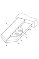
- FIG. 2 is a perspective view showing a specific structure of the sensor unit.
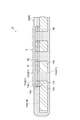
- FIG. 3 is a diagram illustrating a cross section of the sensor unit.
- FIG. 4 is a diagram illustrating the relationship between the voltage provided to the measurement object and the current output from the sensor unit.
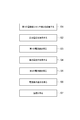
- FIG. 5 is a flowchart showing main steps of the ion concentration measurement method according to the embodiment.
- 6A is a diagram for explaining the operation of the sensor unit when a positive voltage is provided to the measurement object, and FIG. 6B provides a negative voltage to the measurement object. It is a figure for demonstrating operation
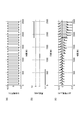
- FIG. 7 is a graph showing the results according to Experimental Example 1.
- FIG. 7 Part (a) of FIG. 7 shows the voltage provided to the measurement object, and part (b) of FIG. 7 shows the ion concentration in the solution.
- FIG. 7C is a diagram showing the current output from the sensor unit.
- FIG. 8 is a graph showing the relationship between the ion concentration in the solution and the current output from the sensor unit.
- FIG. 9 is a diagram for explaining a model according to Experimental Example 2.
- FIG. 10 is a graph showing the results of Experimental Example 3.
- FIG. 11 is a graph showing the results of Experimental Example 4.
- the ion concentration measurement apparatus 1 obtains the concentration of ions contained in the measurement object 100.
- the measurement object 100 includes water 101.
- the water 101 contains ions.
- the measurement object 100 is, for example, soil in which agricultural products are planted.
- the soil contains a predetermined amount of water.
- This water contains various ions such as potassium ions 102.
- the ion concentration measuring apparatus 1 according to the present embodiment will be described using the ion concentration measuring apparatus 1 that measures the concentration of potassium ions 102 in the soil as an example.
- the ions measured by the ion concentration measuring device 1 are not limited to potassium ions. As ions to be measured, desired ions can be selected according to the purpose of measurement.
- the ion concentration (T) is the amount (or number of moles) of ions contained per unit volume. In the following description, the unit volume is 1 liter. The amount (or mole) (mol) of potassium ions contained per liter is defined as the ion concentration (mol / L).
- the ion concentration measuring apparatus 1 includes a first electrode unit 2, a sensor unit 3, and a measuring unit 4 as physical components.
- the measurement unit 4 includes a voltage generation unit 6, an ammeter 7, and a control unit 8.
- the first electrode unit 2 is disposed inside the measurement object 100.
- the first electrode unit 2 provides a predetermined voltage to the measurement object 100.
- the first electrode unit 2 is made of, for example, platinum.
- the 1st electrode part 2 may be comprised with a glass reference electrode or gold
- the first electrode unit 2 provides a voltage to the water 101 in the soil that is the measurement object 100.
- a voltage generation unit 6 is connected to the first electrode unit 2.
- the voltage generator 6 generates a positive pulse voltage or a negative pulse voltage.
- the voltage generator 6 provides a positive pulse voltage or a negative pulse voltage to the first electrode unit 2.
- the voltage provided from the first electrode unit 2 to the measurement object 100 is provided from the voltage generation unit 6.
- the first electrode unit 2 repeatedly supplies a positive voltage (E1) and a negative voltage (E2) to the measurement object 100 alternately.
- the first electrode unit 2 provides +0.5 mV as the positive voltage (E1).
- the first electrode portion 2 provides ⁇ 0.5 mV as the negative voltage (E2) (see the portion (a) in FIG. 7).
- a positive voltage (E1) and a negative voltage (E2) are repeatedly and alternately provided. The period is 100 seconds as an example.
- the sensor unit 3 is separated from the first electrode unit 2 inside the measurement object 100. Therefore, a part of the measurement object 100 is disposed between the sensor unit 3 and the first electrode unit 2. Specifically, water 101 in soil is disposed between the sensor unit 3 and the first electrode unit 2. The sensor unit 3 generates a current. This current corresponds to the voltage provided from the first electrode unit 2 to the measurement object 100. Further, the value of this current is acquired by an ammeter 7 connected to the sensor unit 3.
- the sensor unit 3 includes a capturing unit 9, a conductive unit 11, and a second electrode unit 12.
- the trap 9 selectively captures ions present in the water. That is, the trap 9 is an ion selective functional membrane.
- the capturing unit 9 is configured by a base material including an ionophore.
- a substrate containing an ionophore has a function of selectively capturing ions.
- the capturing unit 9 selectively captures potassium ions 102. Therefore, the trap 9 is a potassium ion sensitive membrane.
- An example of an ionophore that selectively captures potassium ions is valinomycin.
- the trap 9 includes a dopant.
- the dopant includes tetra n-butylammonium perchlorate (TBAClO 4 ).
- the conductive part 11 provides a mediating ion to the capturing part 9. In addition, the conductive part 11 recovers the mediating ions from the capturing part 9.
- the conductive part 11 is made of a conductive polymer material.
- the conductive polymer material reversibly exchanges electrons and ions. Examples of the conductive polymer material include polyethylene dioxythiophene (PEDOT).
- the conductive part 11 includes a dopant. Examples of the dopant include tetra n-butylammonium perchlorate (TBAClO 4 ).
- the second electrode unit 12 is connected to the ground unit 13 through the ammeter 7.
- the ammeter 7 is disposed outside the measurement object 100.
- the second electrode unit 12 provides electrons to the conductive unit 11.
- the second electrode unit 12 collects electrons from the conductive unit 11.
- the 2nd electrode part 12 is comprised with the metal material which has electroconductivity. Examples of the metal material include gold, copper, and aluminum.
- a positive voltage (E1) is provided to the first electrode unit 2
- potassium ions 102 having a positive charge are captured by the capturing unit 9.
- the capturing unit 9 is charged to a positive potential.
- the conductive unit 11 provides a mediating ion having a negative potential to the capturing unit 9.
- the conductive part 11 provides the mediating ions to the trapping part 9, the conductive part 11 is charged to a positive potential.
- the second electrode portion 12 provides electrons having a negative charge to the conductive portion 11 so as to cancel the positive charge in the conductive portion 11.
- the electrons are provided from the ground unit 13.
- An ammeter 7 is provided between the ground unit 13 and the second electrode unit 12.
- the sensor unit 3 further includes a circuit board 14 in addition to the capturing unit 9, the conductive unit 11, and the second electrode unit 12 described above.
- the circuit board 14 includes a conductive pattern.
- the conductive pattern ensures electrical connection between the second electrode portion 12 and the ammeter 7.
- the circuit board 14 is inserted into the measurement object 100. Therefore, the tip of the circuit board 14 has a sharp shape. According to this shape, the circuit board 14 can be easily inserted into the soil.
- the circuit board 14 has a thin plate shape.
- the circular second electrode portion 12 is provided on the main surface 14 a of the circuit board 14. The shape of the second electrode portion 12 is not limited to a circle.
- the second electrode unit 12 may have a desired shape such as a rectangular shape.
- the second electrode portion 12 may be a land provided on the main surface 14a.
- a circular conductive part 11 is provided on the second electrode part 12.
- the conductive part 11 is formed by electroless plating as an example.
- the capturing unit 9 has a capturing surface 9a and a first connection surface 9b.
- the capture surface 9 a contacts the measurement object 100.
- the first connection surface 9b is a surface opposite to the capturing surface 9a.
- the conductive portion 11 has a second connection surface 11a and a third connection surface 11b.
- the 3rd connection surface 11b is a surface on the opposite side to the 2nd connection surface 11a.
- the second connection surface 11 a faces the first connection surface 9 b of the capturing unit 9.
- the second connection surface 11a is electrically connected to the first connection surface 9b.
- the second electrode portion 12 has a fifth connection surface 12a.
- the fifth connection surface 12 a faces the third connection surface 11 b of the conductive portion 11.
- the fifth connection surface 12a is electrically connected to the third connection surface 11b.
- the plurality of through holes 21 are provided in the circuit board 14, the second electrode portion 12, and the conductive portion 11, respectively.
- the plurality of through holes 21 include a hole portion 14c, a hole portion 12c, and a hole portion 11c.
- the hole 14 c is provided in the circuit board 14.
- the hole portion 12 c is provided in the second electrode portion 12.
- the hole portion 11 c is provided in the conductive portion 11.
- the through hole 21 extends from the second connection surface 11 a of the conductive portion 11 to the back surface 14 b of the circuit board 14.
- the capturing unit 9 is provided so as to cover the circuit board 14, the second electrode unit 12, and the conductive unit 11. Specifically, the capturing unit 9 is formed on the main surface 14 a of the circuit board 14, the second connection surface 11 a of the conductive unit 11, the inside of the through hole 21, and the back surface 14 b of the circuit board 14. Provided. Therefore, the capturing unit 9 provided on the second connection surface 11 a of the conductive unit 11 has a function of capturing the potassium ions 102 in the sensor unit 3. The capturing part 9 provided in the above-described place is integrated.
- the second electrode portion 12 is formed of a metal material.
- the conductive portion 11 is formed of a polymer material. Therefore, it is difficult to increase the bonding strength between the second electrode portion 12 and the conductive portion 11.
- the capturing part 9 described above the capturing part 9 provided on the second connection surface 11 a side of the conductive part 11 and the capturing part 9 provided on the back surface 14 b side of the circuit board 14 are provided in the through hole 21. It can also be said that they are connected by the captured part 9. Then, the second electrode portion 12 and the conductive portion 11 are integrated and wrapped by the capturing portion 9 that is difficult to peel off from the circuit board 14.
- the ion concentration measuring apparatus 1 can maintain the function of the sensor unit 3 for a long period of time.
- the control unit 8 controls the operation of the voltage generation unit 6. Further, the control unit 8 obtains the concentration of potassium ions 102 based on the current value provided from the ammeter 7.
- the control unit 8 is a computer system as an example.
- the control unit 8 is physically a main storage device such as a CPU (Central Processing Unit), RAM (Random Access Memory) and ROM (Read Only Memory), an input device such as a keyboard, an output device such as a display, a hard disk, etc. It is configured as a normal computer system including an auxiliary storage device.
- Each function of the control unit 8 to be described later is to operate a input device and an output device under the control of the CPU by reading predetermined computer software on hardware such as a CPU, RAM, ROM, etc. Or by reading and writing data in an auxiliary storage device.
- the control unit 8 includes a recording unit 16, a current value acquisition unit 17, a difference acquisition unit 18, and a concentration acquisition unit 19 as functional components.
- the recording unit 16 is, for example, a ROM.
- the recording unit 16 records the current value provided from the ammeter 7 and the drive signal provided to the voltage generation unit 6 in association with each other.
- the recording unit 16 records the conversion coefficient (D).
- the conversion coefficient (D) is used to obtain the ion concentration (T) using the current value.
- the recording unit 16 is connected to the ammeter 7.
- the recording unit 16 receives the current value.
- the recording unit 16 is connected to the voltage generation unit 6.
- the recording unit 16 receives the drive signal.
- the recording unit 16 is connected to the current value acquisition unit 17.
- the recording unit 16 provides the drive signal and the current value associated with each other to the current value acquisition unit 17.
- the recording unit 16 is connected to the density acquisition unit 19.
- the recording unit 16 provides the conversion coefficient (D) to the density acquisition unit 19.
- the current value acquisition unit 17 obtains a current value. This current value is for obtaining a difference ( ⁇ C) in the current value necessary for obtaining the ion concentration (T).
- the current value acquisition unit 17 is connected to the recording unit 16.
- the current value acquisition unit 17 obtains information in which the time and the current value are associated with each other. Note that the current value acquisition unit 17 may obtain information in which the drive signal and the current value are associated with each other.
- the current value acquisition unit 17 obtains a first current value (C1) and a second current value (C2).
- the current value acquisition unit 17 outputs the first current value (C1) and the second current value (C2) to the difference acquisition unit 18.
- the first current value (C1) is a value of a current generated in the sensor unit 3 when a positive voltage (E1) is provided to the first electrode unit 2. Specifically, the first current value (C1) is a current value at a timing immediately before switching from the positive voltage (E1) to the negative voltage (E2).
- the second current value (C2) is a value of a current generated in the sensor unit 3 when a negative voltage (E2) is provided to the first electrode unit 2. Specifically, the second current value (C2) is a current value at a timing immediately before switching from the negative voltage (E2) to the positive voltage (E1).
- the difference acquisition unit 18 obtains a difference ( ⁇ C) in the current value necessary for acquiring the ion concentration (T).
- the concentration acquisition unit 19 obtains the ion concentration (T).
- the density acquisition unit 19 is connected to the recording unit 16.
- the density acquisition unit 19 receives the conversion coefficient (D).
- the density acquisition unit 19 is connected to the difference acquisition unit 18.
- the density acquisition unit 19 receives the difference ( ⁇ C).
- the concentration acquisition unit 19 outputs the ion concentration (T) to the recording unit 16.
- the conversion coefficient (D) is a coefficient for converting the difference ( ⁇ C) in the current value into the density (T).
- the conversion coefficient (D) is acquired in advance by performing a preliminary test. Then, the conversion coefficient (D) is recorded in the recording unit 16.
- the 1st electrode part 2 and the sensor part 3 are arrange
- a positive voltage (E1) is provided to the measurement object 100 (FIG. 5: Step S2).
- This step S ⁇ b> 2 is performed by the control unit 8, the voltage generation unit 6, and the first electrode unit 2.
- the control unit 8 provides a drive signal.
- This drive signal includes information that causes the voltage generator 6 to output a positive voltage (E1).
- the voltage generator 6 generates a positive voltage (E1) based on the drive signal.
- the voltage generator 6 is provided to the first electrode unit 2.
- the first electrode unit 2 provides a positive voltage (E1) to the measurement object 100.
- potassium ions 102 exist in the measurement object 100.
- the potassium ion 102 has a positive charge.
- This potassium ion 102 is a measurement target of the measurement method according to the present embodiment.
- a positive voltage (E1) is provided to the first electrode unit 2
- the potassium ions 102 having a positive charge move away from the first electrode unit 2.
- the potassium ions 102 are captured by the capturing unit 9 of the sensor unit 3.
- the capturing unit 9 includes an ionophore 22 that selectively captures potassium ions 102. Therefore, another ion different from the potassium ion 102 is not captured by the capturing unit 9.
- the capture unit 9 When the potassium ion 102 is captured by the capture unit 9, the capture unit 9 has a positive charge. At this time, mediating ions are provided from the conductive portion 11 to the capturing portion 9 so as to eliminate the charging of the capturing portion 9.
- the mediator ion has a negative charge.
- the mediating ion in this embodiment is a chlorine ion 104.
- the chlorine ions 104 are based on TBACLO 4 doped in the trap 9 and the conductive portion 11. When chlorine ions 104 having a negative charge are provided from the conductive part 11 to the capturing part 9, the conductive part 11 has a positive charge. At this time, the electrons 103 are provided from the second electrode portion 12 to the conductive portion 11 so as to eliminate the charging of the conductive portion 11.
- the electrons 103 are provided from the ground unit 13. When the electrons 103 move from the ground unit 13 to the second electrode unit 12, a current is generated. The magnitude of the current is obtained by the ammeter 7. The ammeter 7 is disposed between the ground unit 13 and the second electrode unit 12. The current value obtained by the ammeter 7 is output to the control unit 8.
- Step S3 the first current value (C1) is obtained (FIG. 5: Step S3).
- This step S3 is performed by the sensor unit 3, the ammeter 7, and the current value acquisition unit 17 of the control unit 8.
- the control unit 8 acquires the current value output from the sensor unit 3 using the ammeter 7 over a period in which the positive voltage (E1) is provided. Then, the control unit 8 stores the acquired current value in the recording unit 16.
- the absolute value of the current value recorded in the recording unit 16 increases in a spike shape immediately after providing the positive voltage (E1). Thereafter, the absolute value of the current value decreases exponentially. Then, the absolute value of the current value converges to a predetermined value.
- step S3 the current value acquisition unit 17 converges the value (point P1) as the first current value (C1).
- Various methods can be used to obtain the converged value (point P1) as the first current value (C1). For example, you may obtain the average of the electric current value in a convergence period. Further, the current value immediately before switching from the positive voltage (E1) to the negative voltage (E2) may be obtained.
- a negative voltage (E2) is provided to the measurement object 100 (FIG. 5: Step S4).
- This step S4 is performed by the control unit 8, the voltage generation unit 6, and the first electrode unit 2.
- the control unit 8 provides a drive signal.
- This drive signal includes information that causes the voltage generator 6 to output a negative voltage (E2).
- the voltage generator 6 generates a negative voltage (E2) based on the drive signal.
- the voltage generator 6 is provided to the first electrode unit 2.
- the first electrode unit 2 provides the measurement object 100 with a negative voltage (E2).
- the potassium ion 102 is captured by the capturing unit 9 immediately before the negative voltage (E2) is provided. And when the negative voltage (E2) is provided to the 1st electrode part 2, the potassium ion 102 which has a positive charge is attracted to the 1st electrode part 2 to which the negative voltage (E2) was provided. . That is, the potassium ions 102 are released from the capturing unit 9. When the potassium ions 102 are released from the capturing unit 9, the chlorine ions 104 are collected by the conductive unit 11. Chlorine ions 104 are present in the capture unit 9 in order to keep the potential balance of the capture unit 9 balanced.
- the electrons 103 are recovered by the second electrode portion 12.
- the electrons 103 exist in the conductive part 11 in order to keep the balance of the potential of the conductive part 11.
- the electrons 103 collected by the second electrode unit 12 move to the ground unit 13.
- the movement of electrons from the second electrode portion 12 to the ground portion 13 generates a current.
- This direction of current is opposite to the direction of current that occurs when a positive voltage (E1) is provided.
- the magnitude of the current is obtained by the ammeter 7.
- the ammeter 7 is disposed between the second electrode portion 12 and the ground portion 13.
- the current value obtained by the ammeter 7 is output to the control unit 8.
- Step S5 a second current value (C2) is obtained (FIG. 5: Step S5).
- This step S5 is performed by the sensor unit 3, the ammeter 7, and the current value acquisition unit 17 of the control unit 8.
- the control unit 8 acquires the current value output from the sensor unit 3 using the ammeter 7 over a period during which the negative voltage (E2) is provided. Then, the control unit 8 stores the acquired current value in the recording unit 16.
- the absolute value of the current value recorded in the recording unit 16 increases in a spike shape immediately after providing the negative voltage (E2). Thereafter, the absolute value of the current value decreases exponentially. Then, the absolute value of the current value converges to a predetermined value.
- the current value acquisition unit 17 converges the value (point P2) as the second current value (C2).
- step S6 a current value difference ( ⁇ C) is obtained (FIG. 5: step S6).
- This step S6 is performed by the difference acquisition unit 18 of the control unit 8.
- Step S7 the ion concentration (T) is obtained (FIG. 5: Step S7).
- This step S7 is performed by the density acquisition unit 19 of the control unit 8.
- Chlorine ions 104 correspond to the number of potassium ions 102.
- the number of chlorine ions 104 provided to the capture unit 9 corresponds to the electrons 103.
- the electrons 103 are provided from the ground unit 13 to the conductive unit 11 via the second electrode unit 12.
- the chlorine ions 104 are collected from the capturing unit 9 to the conductive unit 11.
- the number of chlorine ions 104 collected in the conductive part 11 corresponds to the electrons 103.
- the electrons 103 move from the second electrode unit 12 to the ground unit 13. Therefore, by obtaining the number of potassium ions 102 captured by the capturing unit 9 and the number of potassium ions 102 released from the capturing unit 9, the value of the current flowing between the ground unit 13 and the second electrode unit 12 is obtained. Is obtained. Therefore, the ion concentration measuring apparatus 1 can detect the current detection type ion concentration (T). According to this structure, the influence of the electric charge which the measurement object 100 has is suppressed. Therefore, the ion concentration measuring apparatus 1 can reduce the influence of noise. Further, the ion concentration measuring apparatus 1 provides the first current value (C1) when a positive voltage (E1) is provided to the measurement object 100 and the negative voltage (E2) to the measurement object 100.
- the ion concentration (T) is obtained by utilizing the difference ( ⁇ C) between the second current value (C2) at the time. According to this difference ( ⁇ C), it is possible to cancel noise superimposed on the first current value (C1) and the second current value (C2). Therefore, the ion concentration measuring apparatus 1 can further reduce the influence of noise.
- the ion concentration measuring apparatus 1 has two configurations that reduce the influence of noise. Therefore, the ion concentration measuring apparatus 1 can directly measure the ion concentration (T) contained in the measurement object 100 even in an environment where a lot of noise occurs. That is, the ion concentration measuring apparatus 1 can perform on-site real-time measurement of the ion concentration.
- the water 101 contained in the soil that is the measurement object 100 may have a predetermined charge.
- the ion concentration (T) is obtained by using a voltage detection type measurement device, the influence of the charge of water is also included in the measurement value. Therefore, first, water is collected as a measurement sample. Subsequently, the collected water is left for a predetermined time. As a result, the water charge is discharged. Then, after standing, the ion concentration (T) is measured. Therefore, the voltage detection type measuring device is not suitable for continuously measuring the ion concentration (T) in the soil.
- the state of water in the soil changes due to irrigation. For example, the state of charge of water changes depending on irrigation. Therefore, the measurement value of the measurement device may fluctuate every time it is measured.
- the ion concentration measuring apparatus 1 and the ion concentration measuring method according to the present embodiment are current detection type apparatuses and methods that obtain the ion concentration (T) as a current value. Therefore, the ion concentration measuring apparatus 1 and the ion concentration measuring method can reduce the influence of the electric charge that the measurement object 100 has. Therefore, the ion concentration measuring apparatus 1 and the ion concentration measuring method can stably obtain the ion concentration (T) even in an environment where water in the measurement object 100 moves with time.
- the present invention is not limited to the embodiment described above.
- the present invention can be variously modified without departing from the gist of the present invention.
- the ion absorption rate of plants and the like is also related to the ratio of a plurality of ions.
- the mineral sensor which concerns on this embodiment can acquire the absolute value of specific ion concentration
- positioning multiple types of sensors in a sensor part and performing data processing by the ratio can also be performed.
- the apparatus and method according to the present embodiment have a feature that measurement is possible when the amount of water is smaller than 100%, such as in a culture medium.
- the data can be converted to data with a water content of 100%, that is, only the solution by interpolating the measurement data using a water content sensor.
- the apparatus according to the present embodiment may further include an EC sensor that can measure the total ion concentration in the present sensor that measures the specific ion concentration. According to this EC sensor, the ratio to the total ion concentration can be calculated. Thereby, specific ion concentration adjustment can be added to appropriate fertilizer concentration (overall ion concentration) management.
- the apparatus according to the present embodiment may appropriately select the above-described configuration according to the purpose. Furthermore, the apparatus according to the present embodiment may have all the above-described configurations.
- Example 1 the ion concentration measuring device 1 was used to confirm the relationship between the ion concentration (T) and the difference ( ⁇ C).
- a positive voltage (E1: + 0.5V) and a negative voltage (E2: ⁇ 0.5V) are repeatedly provided to the measurement object 100. did. The period is 100 seconds.
- the ion concentration (T) of the measurement object 100 provided with such a voltage is set to a first concentration (T: 0.1 mM), a second concentration (T: 1.0 mM), and a third concentration (T: 5 mM) and the fourth concentration (T: 10 mM) was changed stepwise (see part (b) of FIG. 7).
- a time history of the current value shown in part (c) of FIG. 7 was obtained.
- a first current value (C1: (+0.143 ⁇ A)) and a second current value (C2: ⁇ 0.17 ⁇ A) at the first concentration (T: 0.1 mM) were obtained.
- a difference of 1 ( ⁇ C1: 0.31 ⁇ A) was obtained, and the first current value (C1: +0.15 ⁇ A) at the second concentration (T: 1.0 mM) and the second current value (C2: -0.18 ⁇ A) and a second difference ( ⁇ C2: 0.33 ⁇ A), a first current value at a third concentration (T: 5.0 mM) (C1: +0.20 ⁇ A) and a second current value (C2: ⁇ 0.56 ⁇ A) and a third difference ( ⁇ C3: 0.76 ⁇ A) was obtained at a fourth concentration (T: 10 mM).
- a first current value (C1: +0.45 ⁇ A) and a second current value (C2: ⁇ 1.40 ⁇ A) were obtained, and a third difference ( ⁇ C3 1.85Myuei) was obtained.
- T ion concentration
- Example 3 In Experimental Example 3, the results obtained with the ion concentration measuring apparatus 1 according to the present embodiment and the results obtained with the existing current detection type ion concentration measuring apparatus were compared in a common measurement environment.
- an existing current detection type ion concentration measuring apparatus a compact potassium ion meter: B-731 manufactured by HORIBA was used.
- a model 106 was prepared as shown in FIG. Model 106 simulates soil with water containing ions. Model 106 is rock wool.
- the first electrode part 2 and the sensor part 3 of the ion concentration measuring apparatus 1 according to the present embodiment were inserted into the rock wool. Moreover, the water discharged
- FIG. 10 is a graph showing the relationship between the dripping amount of water and the ion concentration measuring apparatus 1.
- FIG. 10 is a graph showing the relationship between the dripping amount of water and the ion concentration measuring device 108.
- Plot B1 shows the cumulative dripping amount of water.
- Plot B2 shows the sensor output of the ion concentration measuring apparatus 1.
- Plot B3 shows the sensor output of the ion concentration measuring apparatus 108.
- Region K1 represents a period during which water having an ion concentration of 17 mM was dropped.
- Region K2 represents a period during which water having an ion concentration of 8.5 mM was dropped. Referring to FIG.
- the ion concentration measuring apparatus 1 can continuously measure the ion concentration (T) in an environment simulating soil.
- Example 4 the stability of the sensor output of the ion concentration measurement apparatus 1 according to this embodiment was confirmed.
- the first electrode unit 2 and the sensor unit 3 of the ion concentration measuring apparatus 1 were inserted into the soil of the cultivation site. Thereafter, sensor output was obtained over time. During this period, no irrigation work is performed. That is, the ion concentration (T) in the soil that is the measurement object 100 is in a stable state.
- FIG. 11 shows the change over time of the sensor output of the ion concentration measuring apparatus 1. As shown in FIG. 11, the sensor output did not have a significant fluctuation that could be attributed to disturbance noise. Therefore, it was found that the ion concentration measuring device 1 arranged in a stable state of the ion concentration (T) can output a stable value.
- the ion concentration measurement apparatus is, in short, an ion concentration measurement apparatus that obtains the concentration of ions existing in a measurement object, and is arranged on the measurement object so that a positive voltage and a negative voltage are applied to the measurement object.
- a first electrode unit that alternately provides a voltage of the voltage, a voltage generation unit that generates the positive voltage and the negative voltage, and a measurement object that is spaced apart from the first electrode,
- a sensor unit that generates a current corresponding to a voltage provided to the measurement object, and controls the voltage generation unit, and the ions present in the measurement object based on a current output from the sensor unit
- a control unit that obtains the concentration of the ion, and the sensor unit includes a capture unit including an ionophore that selectively captures the ions, and the ions that are electrically connected to the capture unit and captured by the capture unit
- a second electrode unit that collects the electrons from the conductive unit, and the control unit is provided with the positive voltage to the measurement object.
- a current value acquisition unit that obtains a first current value generated by the sensor unit when the negative voltage is provided to the measurement target, and a second current value generated by the sensor unit when the negative voltage is provided to the measurement object
- a difference acquisition unit that obtains a difference between the first current value and the second current value
- a concentration acquisition unit that obtains the concentration of the ions based on the difference.
- the ion concentration measurement method is an ion concentration measurement method for obtaining a concentration of ions existing in a measurement object, and provides a positive voltage to the measurement object via a first electrode unit.
- the positive voltage is applied to the measurement object.
- a capture unit including an ionophore that selectively captures the ions captures the ions, and the ions are captured by the capture unit, whereby the capture ions corresponding to the ions captured by the capture unit are captured.
- the conductive portion provided to the capturing portion provides the mediating ions to the capturing portion, and the mediating ions are provided to the capturing portion, whereby electrons corresponding to the mediating ions provided to the capturing portion are supplied to the conducting portion.
- the negative voltage is provided to the object to be measured.
- the trapped ions are released from the trapping unit, and the ions are released from the trapping unit, whereby the conductive unit collects the intermediate ions from the trapping unit, and By intervention ions is recovered, the second electrode portion to recover the electrons from the conductive portion.
- SYMBOLS 1 Ion concentration measuring device, 2 ... 1st electrode part, 3 ... Sensor part, 4 ... Measurement unit, 6 ... Voltage generation part, 8 ... Control part, 9 ... Capture part, 11 ... Conductive part, 12 ... 2nd Electrode part, 13 ... grounding part, 14 ... circuit board, 21 ... through hole, 16 ... recording part, 17 ... current value acquisition part, 18 ... difference acquisition part, 19 ... concentration acquisition part, 22 ... ionophore, 100 ... measurement Object, 101 ... water, 102 ... potassium ion, 103 ... electron, 104 ... chlorine ion (mediating ion).
Landscapes
- Chemical & Material Sciences (AREA)
- Chemical Kinetics & Catalysis (AREA)
- Electrochemistry (AREA)
- Physics & Mathematics (AREA)
- Health & Medical Sciences (AREA)
- Life Sciences & Earth Sciences (AREA)
- Analytical Chemistry (AREA)
- Biochemistry (AREA)
- General Health & Medical Sciences (AREA)
- General Physics & Mathematics (AREA)
- Immunology (AREA)
- Pathology (AREA)
- Investigating Or Analyzing Materials By The Use Of Electric Means (AREA)
Abstract
イオン濃度測定装置1は、ノイズの影響を抑制し、計測対象物に含まれたイオン濃度を直接に測定する。具体的には、イオン濃度測定装置1は、計測対象物100に存在するカリウムイオン102の濃度を得る。イオン濃度測定装置1は、第1の電極部2と、電圧発生部6と計測対象物100に提供される電圧に対応した電流を発生させるセンサ部3と、センサ部3から出力される電流に基づいてカリウムイオン102の濃度を得る制御部8と、を備える。制御部8は、正の電圧が提供されたときにセンサ部3が発生する第1の電流値(C1)と、負の電圧が提供されたときにセンサ部3が発生する第2の電流値(C2)と、を得る電流値取得部17と、第1の電流値(C1)と第2の電流値(C2)の差分(ΔC)を得る差分取得部18と、差分(ΔC)に基づいてイオン濃度(T)を得る濃度取得部19と、を有する。
Description
本発明は、計測対象物に存在するイオン濃度を得るイオン濃度測定装置及びイオン濃度測定方法に関する。
農業分野では、特定の成分を多く含むいわゆる機能性野菜が注目されている。近年の研究結果は、野菜に含まれる成分と土壌中の特定のイオンとに関係があることを示している。特定のイオンの濃度を計測する技術として、例えば、炎光光度計や液体クロマトグラフィーなどが知られている。
さらに、イオン濃度の計測技術を利用する分野では、計測作業の簡便化が望まれていた。このような技術には、土壌又は培地から標本を採取し、当該標本を利用してイオン濃度を測定する技術がある。例えば、可搬型のカリウムイオン計測器は、土壌中の水をスポイトを用いて採取し、当該水を利用してイオン濃度を測定する。また、酸化還元反応を利用した計測器も知られている。
R. Ishimatsu, A. Izadyar, B. Kabagambe, Y. Kim, J. Kim, and S.Amemiya, J. Am. Chem. Soc., vol. 133, Issue 40, pp. 16300-16308 , 2011.
S. Mizutani, S. Takahashi, A. Kono, T. Hattori, T. Iwata, M. Ishida, K. Sawada, IEEE Sensors 2015 Conference, Busan, South Korea, Nov. 1-4, 2015.
しかしながら、標本採取による測定は、標本の採取と計測作業とに手間を要する。従って、標本採取による測定は、土壌中のイオン濃度を継続的に監視するといった用途には不向きである。そこで、土壌そのものに計測器を配置して、イオン濃度を測定する技術が検討されている。このようなイオン濃度を測定する技術として、イオン選択膜を利用して測定対象のイオンを選択し、選択されたイオンの濃度を電圧又は電流を利用して得る手法がある。
電圧を利用する手法(以下「電圧検出型」と呼ぶ)の計測レンジは、単位容積(1リットル)あたり10μmolから0.1mol程度である。一方、電圧検出型は、イオン濃度の変化に対する電圧の変化が小さい。従って、イオン濃度の微小な変化を検出することが困難である。具体的には、電圧検出型において、イオン濃度が一桁変わったときの電圧の変化は理論的に59mVである。従って、電圧検出型を利用した測定は、ノイズの影響を受けやすい。
電流を利用する手法(以下「電流検出型」と呼ぶ)は、酸化還元電流を利用する。例えば、電流検出型に関する技術として、PEDOT構造(非特許文献1)及び、当該PEDOT構造を利用した電流検出型のセンサ(非特許文献2)が知られている。電流検出型では、電流値がイオン濃度に比例する。従って、電流検出型は、電圧検出型よりも高い分解能を有する。しかし、電流検出型を利用した測定は、電流のピークを利用してイオン濃度を得る。従って、電流検出型を利用した測定は、スパイクノイズの影響を受けやすい。
本発明は、ノイズの影響を抑制し、計測対象物に含まれたイオン濃度を直接に測定できるイオン濃度測定装置及びイオン濃度測定方法を提供することを目的とする。
本発明の一形態に係るイオン濃度測定装置は、計測対象物に正の電圧と負の電圧とを交互に提供する第1の電極部と、電圧を発生させる電圧発生部と、計測対象物に提供される電圧に対応して選択的に捕捉されるイオンに基づく電流を発生させるセンサ部と、電圧発生部を制御すると共に、センサ部から出力される電流に基づいて、計測対象物に存在するイオンの濃度を得る制御部と、を備え、制御部は、計測対象物へ正の電圧が提供されたときにセンサ部が発生する第1の電流値と、計測対象物へ負の電圧が提供されたときにセンサ部が発生する第2の電流値と、を得る電流値取得部と、第1の電流値と第2の電流値との差分を得る差分取得部と、差分に基づいてイオンの濃度を得る濃度取得部と、有する。
この測定装置では、電圧発生部により発生された正の電圧及び負の電圧が第1の電極部から計測対象物に提供される。センサ部は、計測対象物に提供された電圧に対応して選択的に捕捉されるイオンに基づく電流を発生させる。従って、この測定装置は、電流検出型のイオン濃度の検出を行うことができる。この検出構成によれば、計測対象物が有する電荷の影響が抑制される。従って、測定装置は、ノイズの影響を低減できる。さらに、測定装置は、計測対象物に正の電圧を提供したときの第1の電流値と、計測対象物に負の電圧を提供したときの第2の電流値と、の差分を利用して、イオン濃度を得る。この差分を利用すれば、第1の電流値と第2の電流値とに重畳するノイズを相殺することが可能である。従って、測定装置は、ノイズの影響をさらに低減できる。よって、測定装置は、ノイズの影響を低減する2つの構成を有する。従って、測定装置は、ノイズが多く発生する環境においても、計測対象物に含まれたイオン濃度を直接に測定することができる。
センサ部は、イオンを選択的に捕捉するイオノフォアを含む捕捉部と、捕捉部に電気的に接続され、捕捉部に捕捉されたイオンに対応する媒介イオンを捕捉部へ提供すると共に、媒介イオンを捕捉部から回収する導電部と、導電部及び接地部に電気的にそれぞれ接続され、捕捉部へ提供された媒介イオンに対応する電子を導電部に提供すると共に、電子を導電部から回収する第2の電極部と、を備えてもよい。この構成によれば、陽イオンの検出を例に示すと、捕捉部にイオンが捕捉されたとき、補足イオンに対応する媒介イオンは、導電部から捕捉部に提供される。そして、捕捉部に提供された媒介イオンに対応する電子は、接地部から第2の電極部を介して導電部に提供される。一方、捕捉部からイオンが解放されたとき、解放されたイオンに対応する媒介イオンは、捕捉部から導電部に回収される。そして、導電部に回収された媒介イオンに対応する電子は、第2電極部から接地部に移動する。従って、捕捉部に捕捉されたイオンを接地部と第2の電極部との間を流れる電流の値として得ることができる。また、捕捉部から解放されたイオンを接地部と第2の電極部との間を流れる電流の値として得ることができる。なお、陰イオンの検出方法はその反対となる。従って、測定装置は、電流検出型のイオン濃度の検出を行うことができる。
センサ部は、基板をさらに有し、第2の電極部は、基板に設けられ、導電部は、第2の電極部上に設けられ、基板、第2の電極部、導電部には、基板の裏面から導電部の主面に至る貫通孔が設けられ、捕捉部は、導電部の主面と貫通孔と基板の裏面とに一体的に設けられてもよい。この捕捉部によれば、導電部の主面側に設けられた捕捉部と、基板の裏面側に設けられた捕捉部とが貫通孔に設けられた捕捉部によって連結されている。従って、第2の電極部と導電部とは、一体化された捕捉部によって包み込まれる。この構成によれば、計測対象物に対するセンサ部の差し込みと引き抜きが繰り返されたとき、第2の電極部と導電部との間に隙間が発生することが抑制される。従って、第2の電極部と導電部との間の電気的な接続を維持することが可能になる。従って、測定装置は、センサ部の機能を長期間に亘って維持することができる。
導電部は、電子とイオンとを可逆的に授受可能な導電性高分子を含んでもよい。この構成によれば、媒介イオンを好適に捕捉部へ提供することができる。さらにこの構成によれば、媒介イオンを捕捉部から回収することができる。
本発明の別の形態に係るイオン濃度測定方法は、計測対象物に第1の電極部を介して正の電圧を提供することにより、正の電圧に対応して選択的に捕捉されるイオンに基づく電流を発生させるセンサ部が発生する第1の電流値を得るステップと、計測対象物に第1の電極部を介して負の電圧を提供することにより、センサ部が発生する第2の電流値を得るステップと、第1の電流値と第2の電流値との差分を得るステップと、差分に基づいてイオンの濃度を得るステップと、を有する。
この測定方法は、計測対象物に正の電圧を提供したときに、捕捉部に捕捉されたイオンに対応する第1の電流値を得る。また、計測対象物に負の電圧を提供したときに、捕捉部から解放されたイオンに対応する第2の電流値を得る。従って、この測定方法は、捕捉部に捕捉されたイオン及び捕捉部から解放されたイオンを接地部と第2の電極部との間を流れる電流の値として得る電流検出型のイオン濃度の検出を行うことができる。この測定方法によれば、計測対象物が有する電荷の影響が抑制されるので、ノイズの影響を低減できる。さらに、この測定方法は、第1の電流値と第2の電流値との差分を利用して、イオン濃度を得る。差分を得るステップによれば、第1の電流値と第2の電流値とに重畳するノイズが相殺される。従って、ノイズの影響をさらに低減できる。よって、この測定装置によれば、ノイズの影響を低減する2つの作用を有するので、ノイズが多く発生する環境においても、計測対象物に含まれたイオン濃度を直接に測定することができる。
本発明によれば、ノイズの影響を抑制し、計測対象物に含まれたイオン濃度を直接に測定できるイオン濃度測定装置及びイオン濃度測定方法が提供される。
以下、添付図面を参照しながら本発明を実施するための形態を詳細に説明する。図面の説明において同一の要素には同一の符号を付す。また、重複する説明は、省略する。
図1に示されるように、イオン濃度測定装置1は、計測対象物100に含まれたイオンの濃度を得る。計測対象物100は、水101を含む。水101は、イオンを含む。計測対象物100は、例えば、農作物が植えられた土壌である。土壌は、所定量の水を含む。この水は、カリウムイオン102といった種々のイオンを含む。以下、土壌中のカリウムイオン102の濃度を測定するイオン濃度測定装置1を例に、本実施形態に係るイオン濃度測定装置1を説明する。なお、イオン濃度測定装置1によって測定されるイオンは、カリウムイオンに限定されることはない。測定対象であるイオンは、計測の目的に応じて所望のイオンを選択できる。また、イオン濃度(T)とは、単位体積当たりに含まれるイオンの物質量(もしくはモル数)である。以下の説明では、単位体積を1リットルとする。そして、1リットルあたりに含まれるカリウムイオンの物質量(もしくはモル数)(mol)を、イオン濃度(mol/L)とする。
イオン濃度測定装置1は、物理的な構成要素として、第1の電極部2と、センサ部3と、計測ユニット4と、を有する。計測ユニット4は、電圧発生部6と、電流計7と、制御部8、とを有する。
第1の電極部2は、計測対象物100の内部に配置される。第1の電極部2は、計測対象物100に対して所定の電圧を提供する。第1の電極部2は、例えばプラチナにより構成される。なお、第1の電極部2は、ガラス参照電極や金により構成されてもよい。第1の電極部2は、計測対象物100である土壌中の水101に電圧を提供する。第1の電極部2には、電圧発生部6が接続される。電圧発生部6は、正のパルス電圧又は負のパルス電圧を発生する。そして電圧発生部6は、正のパルス電圧又は負のパルス電圧を第1の電極部2へ提供する。第1の電極部2から計測対象物100に対して提供される電圧は、電圧発生部6から提供される。第1の電極部2は、計測対象物100に対して正の電圧(E1)及び負の電圧(E2)を交互に繰り返し提供する。例えば、第1の電極部2は、正の電圧(E1)として+0.5mVを提供する。また、第1の電極部2は、負の電圧(E2)として-0.5mVを提供する(図7の(a)部参照)。正の電圧(E1)と負の電圧(E2)とは繰り返し交互に提供される。その周期は一例として100秒である。
センサ部3は、計測対象物100の内部において、第1の電極部2から離間している。従って、センサ部3と第1の電極部2との間には、計測対象物100の一部が配置される。具体的には、センサ部3と第1の電極部2との間には、土壌中の水101が配置される。センサ部3は、電流を発生させる。この電流は、第1の電極部2から計測対象物100に提供された電圧に対応する。また、この電流の値は、センサ部3に接続された電流計7により取得される。センサ部3は、捕捉部9と、導電部11と、第2の電極部12と、を有する。
捕捉部9は、水に存在するイオンを選択的に捕捉する。すなわち、捕捉部9は、イオン選択性の機能膜である。捕捉部9は、イオノフォアを含む基材により構成される。イオノフォアを含む基材は、イオンを選択的に捕捉する機能を有する。一例として、捕捉部9は、カリウムイオン102を選択的に捕捉する。従って、捕捉部9は、カリウムイオン感応膜である。カリウムイオンを選択的に捕捉するイオノフォアとして、バリノマイシンが挙げられる。捕捉部9は、ドーパントを含む。ドーパントには、過塩素酸テトラn-ブチルアンモニウム(TBAClO4)が挙げられる。
導電部11は、捕捉部9に媒介イオンを提供する。また、導電部11は、捕捉部9から媒介イオンを回収する。導電部11は、導電性高分子材料により構成される。導電性高分子材料は、電子とイオンとを可逆的に授受する。導電性高分子材料として、ポリエチレンジオキシチオフェン(PEDOT)が挙げられる。導電部11は、ドーパントを含む。ドーパントとして、過塩素酸テトラn-ブチルアンモニウム(TBAClO4)が挙げられる。
第2の電極部12は、電流計7を介して接地部13に接続される。電流計7は、計測対象物100の外部に配置される。第2の電極部12は、導電部11に対して電子を提供する。また、第2の電極部12は、導電部11から電子を回収する。第2の電極部12は、導電性を有する金属材料により構成される。金属材料として、金、銅、アルミニウムが挙げられる。
第1の電極部2に正の電圧(E1)が提供されたとき、正の電荷を有するカリウムイオン102は、捕捉部9に捕捉される。捕捉部9にカリウムイオン102が捕捉されたとき、捕捉部9は正の電位に帯電する。この捕捉部における正の帯電を打ち消すように、導電部11は、負の電位を有する媒介イオンを捕捉部9に提供する。導電部11が媒介イオンを捕捉部9に提供したとき、導電部11は正の電位に帯電する。この導電部11における正の帯電を打ち消すように、第2の電極部12は、負の電荷を有する電子を導電部11に提供する。この電子は、接地部13から提供される。接地部13と第2の電極部12との間には、電流計7が設けられる。従って、接地部13から第2の電極部12へ電子が提供されたとき、電流が発生する。この電流の大きさは、捕捉部9に捕捉されたカリウムイオン102の量に対応する。従って、カリウムイオン102の濃度は、電流計7により取得される電流の大きさを利用することにより得られる。
ここで、センサ部3の具体的な構造を例示する。図2に示されるように、センサ部3は、上述した捕捉部9と導電部11と第2の電極部12とに加えて、さらに回路基板14を有する。回路基板14は、導電パターンを含む。導電パターンは、第2の電極部12と電流計7との電気的な接続を確保する。また、回路基板14は、計測対象物100に差し込まれる。そこで回路基板14の先端部は、鋭利な形状を有する。この形状によれば、回路基板14を土壌へ容易に差し込むことができる。回路基板14は薄板形状を有する。回路基板14の主面14a上には、円形状の第2の電極部12が設けられる。なお、第2の電極部12の形状は円形に限定されることはない。第2の電極部12は、矩形状といった所望の形状としてもよい。例えば、第2の電極部12は、主面14a上に設けられたランドであってもよい。第2の電極部12上には、円形状の導電部11が設けられる。導電部11は、一例として無電解めっきにより形成される。
図3に示されるように、捕捉部9は、捕捉面9aと第1の接続面9bとを有する。捕捉面9aは、計測対象物100に接触する。第1の接続面9bは、捕捉面9aとは逆側の面である。導電部11は、第2の接続面11aと第3の接続面11bとを有する。第3の接続面11bは、第2の接続面11aとは逆側の面である。第2の接続面11aは、捕捉部9の第1の接続面9bと対面する。第2の接続面11aは、第1の接続面9bに対して電気的に接続される。第2の電極部12は、第5の接続面12aを有する。第5の接続面12aは、導電部11の第3の接続面11bと対面する。第5の接続面12aは、第3の接続面11bに対して電気的に接続される。
複数の貫通孔21は、回路基板14、第2の電極部12及び導電部11にそれぞれ設けられる。具体的には、複数の貫通孔21は、孔部14cと孔部12cと孔部11cとを含む。孔部14cは、回路基板14に設けられる。孔部12cは、第2の電極部12に設けられる。孔部11cは、導電部11に設けられる。貫通孔21は、導電部11の第2の接続面11aから回路基板14の裏面14bに至る。
捕捉部9は、回路基板14と第2の電極部12と導電部11とを覆うように設けられる。具体的には、捕捉部9は、回路基板14の主面14a上と、導電部11の第2の接続面11a上と、貫通孔21の内部と、回路基板14の裏面14b上と、に設けられる。従って、導電部11の第2の接続面11a上に設けられた捕捉部9は、センサ部3においてカリウムイオン102を捕捉する機能を有する。上述した箇所に設けられた捕捉部9は、一体化される。
ここで、第2の電極部12は金属材料により形成される。一方、導電部11は高分子材料により形成される。従って、第2の電極部12と導電部11との接合強度を高めることは難しい。上述した捕捉部9によれば、導電部11の第2の接続面11a側に設けられた捕捉部9と、回路基板14の裏面14b側に設けられた捕捉部9とが貫通孔21に設けられた捕捉部9によって連結されているとも言える。そして、第2の電極部12と導電部11とは、一体化されて回路基板14から剥がれ落ちにくい捕捉部9によって包み込まれる。従って、計測対象物100である土壌に対するセンサ部3の差し込みと引き抜きが繰り返されたとき、第2の電極部12と導電部11との間に隙間が発生することが抑制される。従って、イオン濃度測定装置1は、センサ部3の機能を長期間に亘って維持することができる。
図1に示されるように、制御部8は、電圧発生部6の動作を制御する。また、制御部8は、電流計7から提供される電流値に基づいてカリウムイオン102の濃度を得る。制御部8は、一例としてコンピュータシステムである。制御部8は、物理的には、CPU(Central Processing Unit)、RAM(Random Access Memory)及びROM(Read Only Memory)等の主記憶装置、キーボード等の入力デバイス、ディスプレイ等の出力デバイス、ハードディスク等の補助記憶装置などを含む通常のコンピュータシステムとして構成される。後述する制御部8の各機能は、CPU、RAM、ROM等のハードウェア上に所定のコンピュータソフトウェアを読み込ませることにより、CPUの制御の元で入力デバイス及び出力デバイスを動作させると共に、主記憶装置や補助記憶装置におけるデータの読み出し及び書き込みを行うことで実現される。
制御部8は、機能的構成要素として、記録部16と、電流値取得部17と、差分取得部18と、濃度取得部19と、を有する。記録部16は、例えば、ROMである。記録部16は、電流計7から提供される電流値と、電圧発生部6に提供される駆動信号とを関連付けて記録する。また、記録部16は、変換係数(D)を記録する。変換係数(D)は、電流値を利用してイオン濃度(T)を得るために用いられる。記録部16は、電流計7に接続される。そして記録部16は、電流値を受け取る。記録部16は、電圧発生部6に接続される。そして記録部16は駆動信号を受け取る。また、記録部16は、電流値取得部17に接続される。そして記録部16は、互いに関連付けられた駆動信号と電流値とを電流値取得部17へ提供する。また記録部16は、濃度取得部19に接続される。そして記録部16は、変換係数(D)を濃度取得部19へ提供する。
電流値取得部17は、電流値を得る。この電流値は、イオン濃度(T)の取得に必要な電流値の差分(ΔC)を得るためのものである。電流値取得部17は、記録部16に接続される。そして電流値取得部17は、時間と電流値とが関連付けられた情報を得る。なお、電流値取得部17は、駆動信号と電流値とが関連付けられた情報を得てもよい。電流値取得部17は、第1の電流値(C1)と第2の電流値(C2)とを得る。電流値取得部17は、第1の電流値(C1)と第2の電流値(C2)とを差分取得部18に出力する。
第1の電流値(C1)は、第1の電極部2に正の電圧(E1)が提供されたときにセンサ部3において発生する電流の値である。具体的には、第1の電流値(C1)は、正の電圧(E1)から負の電圧(E2)に切り替わる直前のタイミングにおける電流値である。第2の電流値(C2)は、第1の電極部2に負の電圧(E2)が提供されたときにセンサ部3において発生する電流の値である。具体的には、第2の電流値(C2)は、負の電圧(E2)から正の電圧(E1)に切り替わる直前のタイミングにおける電流値である。
差分取得部18は、イオン濃度(T)の取得に必要な電流値の差分(ΔC)を得る。差分取得部18は、電流値取得部17に接続される。そして差分取得部18は、第1の電流値(C1)と第2の電流値(C2)とを受け取る。差分取得部18は、第1の電流値(C1)と第2の電流値(C2)との差分(ΔC=C1-C2)を算出する。差分取得部18は、当該差分(ΔC)を濃度取得部19に出力する。
濃度取得部19は、イオン濃度(T)を得る。濃度取得部19は、記録部16に接続される。そして濃度取得部19は変換係数(D)を受け取る。さらに濃度取得部19は差分取得部18に接続される。そして濃度取得部19は差分(ΔC)を受け取る。濃度取得部19は、変換係数(D)と差分(ΔC)とを利用して、イオン濃度(T=D×ΔC)を得る。濃度取得部19は、イオン濃度(T)を記録部16に出力する。ここで、変換係数(D)とは、電流値の差分(ΔC)を濃度(T)に変換する係数である。変換係数(D)は、予備的な試験を実施して予め取得される。そして、変換係数(D)は、記録部16に記録される。
次に、イオン濃度測定装置1を利用したイオン濃度(T)の測定方法について、図4、図5及び図6を参照しつつ説明する。
まず、第1の電極部2とセンサ部3とを計測対象物100の内部に配置する(図5:ステップS1)。例えば、第1の電極部2とセンサ部3とが棒状である場合には、それらをそれぞれ計測対象物100である土壌へ差し込む。このとき、第1の電極部2とセンサ部3とは、互いに1cm程度離間させる。
次に、計測対象物100に正の電圧(E1)を提供する(図5:ステップS2)。このステップS2は、制御部8と電圧発生部6と第1の電極部2とにより行われる。制御部8は、駆動信号を提供する。この駆動信号は、電圧発生部6に正の電圧(E1)を出力させる情報を含む。電圧発生部6は、駆動信号に基づいて正の電圧(E1)を発生させる。そして電圧発生部6は、第1の電極部2に提供する。そして、第1の電極部2は、正の電圧(E1)を計測対象物100に提供する。
ここで、計測対象物100に正の電圧(E1)を提供したときにおけるセンサ部3の動作について詳細に説明する。
図6の(a)部に示されるように、計測対象物100には、カリウムイオン102が存在する。カリウムイオン102は、正の電荷を有する。このカリウムイオン102は、本実施形態に係る測定方法の測定対象である。第1の電極部2に正の電圧(E1)が提供されたとき、正の電荷を有するカリウムイオン102は、第1の電極部2から遠ざかる。そしてカリウムイオン102は、センサ部3の捕捉部9に捕捉される。ここで、捕捉部9はカリウムイオン102を選択的に捕捉するイオノフォア22を含む。従って、カリウムイオン102とは異なる別のイオンが捕捉部9に捕捉されることはない。
捕捉部9にカリウムイオン102が捕捉されたとき、捕捉部9は、正の電荷を有する。このとき、捕捉部9の帯電を解消するように、導電部11から媒介イオンが捕捉部9に提供される。媒介イオンは、負の電荷を有する。本実施形態における媒介イオンは、塩素イオン104である。塩素イオン104は、捕捉部9と導電部11とにドープされたTBACLO4に基づく。導電部11から捕捉部9に負の電荷を有する塩素イオン104が提供されたとき、導電部11は、正の電荷を有する。このとき、導電部11の帯電を解消するように、第2の電極部12から電子103が導電部11に提供される。電子103は、接地部13から提供される。接地部13から第2の電極部12に電子103が移動するとき、電流が発生する。電流の大きさは、電流計7により得られる。電流計7は、接地部13と第2の電極部12との間に配置される。電流計7により得た電流値は、制御部8に出力される。
次に、第1の電流値(C1)を得る(図5:ステップS3)。このステップS3は、センサ部3と、電流計7と、制御部8の電流値取得部17とにより行われる。制御部8は、正の電圧(E1)を提供している期間に亘って、電流計7を利用してセンサ部3から出力される電流値を取得する。そして制御部8は、取得した電流値を記録部16に保存する。図4の(b)部に示されるように、記録部16に記録される電流値の絶対値は、正の電圧(E1)を提供した直後にスパイク状に増加する。その後、電流値の絶対値は、指数関数的に減少する。そして、電流値の絶対値は、所定の値に収束する。ステップS3では、電流値取得部17が収束した値(点P1)を第1の電流値(C1)として得る。なお、収束した値(点P1)を第1の電流値(C1)として得る方法は、種々の方法を取り得る。例えば、収束期間における電流値の平均を得てもよい。また、正の電圧(E1)から負の電圧(E2)に切り替わる直前の電流値を得てもよい。
次に、計測対象物100に負の電圧(E2)を提供する(図5:ステップS4)。このステップS4は、制御部8と電圧発生部6と第1の電極部2とにより行われる。制御部8は、駆動信号を提供する。この駆動信号は、電圧発生部6に負の電圧(E2)を出力させる情報を含む。電圧発生部6は、駆動信号に基づいて負の電圧(E2)を発生させる。そして電圧発生部6は、第1の電極部2に提供する。そして、第1の電極部2は、負の電圧(E2)を計測対象物100に提供する。
ここで、計測対象物100に負の電圧(E2)を提供したときにおけるセンサ部3の動作について詳細に説明する。負の電圧(E2)を提供したときには、正の電圧(E1)を提供したときとは逆の動作が行われる。
図6の(b)部に示されるように、負の電圧(E2)が提供される直前、カリウムイオン102は捕捉部9に捕捉されている。そして、第1の電極部2に負の電圧(E2)が提供されたとき、正の電荷を有するカリウムイオン102は、負の電圧(E2)が提供された第1の電極部2に引き寄せられる。すなわち、カリウムイオン102は、捕捉部9から解放される。捕捉部9からカリウムイオン102が解放されたとき、塩素イオン104が導電部11に回収される。塩素イオン104は、捕捉部9の電位のバランスを保つために捕捉部9に存在している。塩素イオン104が導電部11に回収されたとき、電子103が第2の電極部12に回収される。電子103は、導電部11の電位のバランスを保つために導電部11に存在している。第2の電極部12に回収された電子103は、接地部13に移動する。この第2の電極部12から接地部13への電子の移動は、電流を生じさせる。この電流の向きは、正の電圧(E1)を提供したときに生じる電流の向きと逆である。電流の大きさは、電流計7により得られる。電流計7は第2の電極部12と接地部13との間に配置される。電流計7により得た電流値は、制御部8に出力される。
次に、第2の電流値(C2)を得る(図5:ステップS5)。このステップS5は、センサ部3と、電流計7と、制御部8の電流値取得部17とにより行われる。制御部8は、負の電圧(E2)を提供している期間に亘って、センサ部3から出力される電流値を電流計7を利用して取得する。そして制御部8は、取得した電流値を記録部16に保存する。図4の(b)部に示されるように、記録部16に記録される電流値の絶対値は、負の電圧(E2)を提供した直後にスパイク状に増加する。その後、電流値の絶対値は、指数関数的に減少する。そして、電流値の絶対値は、所定の値に収束する。ステップS5では、電流値取得部17が収束した値(点P2)を第2の電流値(C2)として得る。
次に、電流値の差分(ΔC)を得る(図5:ステップS6)。このステップS6は、制御部8の差分取得部18が行う。差分取得部18は、第1の電流値(C1)と第2の電流値(C2)との差分(ΔC=C1-C2)を得る。
次に、イオン濃度(T)を得る(図5:ステップS7)。このステップS7は、制御部8の濃度取得部19が行う。濃度取得部19は、差分(ΔC)と変換係数(D)とを利用して、カリウムイオン102の濃度(T=D×ΔC)を得る。
以上のステップS1~S7を行うことにより、カリウムイオン102の濃度が得られる。
本実施形態に係るイオン濃度測定装置1及びイオン濃度測定方法では、捕捉部9にカリウムイオン102が捕捉されたとき、塩素イオン104が導電部11から捕捉部9に提供される。塩素イオン104は、カリウムイオン102の数に対応する。捕捉部9に提供された塩素イオン104の数は、電子103に対応する。この電子103は、接地部13から第2の電極部12を介して導電部11に提供される。一方、捕捉部9からカリウムイオン102が解放されたとき、塩素イオン104が捕捉部9から導電部11に回収される。導電部11に回収された塩素イオン104の数は、電子103に対応する。そして、この電子103は第2の電極部12から接地部13に移動する。従って、捕捉部9に捕捉されたカリウムイオン102の数及び捕捉部9から解放されたカリウムイオン102の数を得ることにより、接地部13と第2の電極部12との間を流れる電流の値が得られる。従って、イオン濃度測定装置1は、電流検出型のイオン濃度(T)の検出を行うことができる。この構成によれば、計測対象物100が有する電荷の影響が抑制される。従って、イオン濃度測定装置1は、ノイズの影響を低減できる。さらに、このイオン濃度測定装置1は、計測対象物100に正の電圧(E1)を提供したときの第1の電流値(C1)と、計測対象物100に負の電圧(E2)を提供したときの第2の電流値(C2)と、の差分(ΔC)を利用して、イオン濃度(T)を得る。この差分(ΔC)によれば、第1の電流値(C1)と第2の電流値(C2)とに重畳するノイズを相殺することが可能である。従って、イオン濃度測定装置1は、ノイズの影響をさらに低減できる。イオン濃度測定装置1は、ノイズの影響を低減する2つの構成を有する。従って、イオン濃度測定装置1は、ノイズが多く発生する環境においても、計測対象物100に含まれたイオン濃度(T)を直接に測定することができる。すなわち、イオン濃度測定装置1は、イオン濃度のオンサイト・リアルタイム計測が可能である。
ここで、計測対象物100である土壌に含まれる水101は、所定の電荷を有することがある。例えば、電圧検出型の測定装置を利用してイオン濃度(T)を得るとき、水が有する電荷の影響も測定値に含まれてしまう。そこで、まず、測定サンプルとして水を採取する。続いて、採取した水を所定時間放置する。この放置により、水の電荷が放電される。そして、放置の後に、イオン濃度(T)の測定を行う。従って、電圧検出型の測定装置は、土壌中のイオン濃度(T)を連続的に測定することには不向きである。また、土壌中の水の状態は、灌水などによって変化する。例えば、水が有する電荷の状態は、灌水などによって変化する。従って、電圧検出型の測定装置は、測定する毎に測定装置の測定値が変動することもある。
一方、本実施形態に係るイオン濃度測定装置1及びイオン濃度測定方法は、イオン濃度(T)を電流値として得る電流検出型の装置及び方法である。従って、イオン濃度測定装置1及びイオン濃度測定方法は、計測対象物100が有する電荷の影響を低減できる。従って、イオン濃度測定装置1及びイオン濃度測定方法は、経時的に計測対象物100中の水が移動する環境であっても、イオン濃度(T)を安定して得ることができる。
本発明は、前述した実施形態に限定されない。本発明は、本発明の要旨を逸脱しない範囲で種々の変形が可能である。
植物体などのイオン吸収率は複数のイオン同士の比率にも関係する。本実施形態に係るミネラルセンサは特定イオン濃度の絶対値を取得できるが、センサ部に複数種類のセンサを配置しその比率によりデータ処理する手法も行える。
本実施形態に係る装置及び方法は、培地内など水分量が100%より小さい場合の計測ができるという特徴を有する。水分量100%より小さい培地内を計測する時、水分量センサを用いて計測データの補間を行うことにより、水分量が100%、即ち溶液のみのデータへと変換ができる。これにより、計測データを追肥のための肥料の調合へと役立てることができる。例えば、水分量50%、計測データが1mmol/Lと得られた場合、1/0.5=2mmol/Lが溶液100%時の濃度と算出できる。
本実施形態に係る装置は、特定イオン濃度を計測する本センサに総イオン濃度を計測できるECセンサをさらに備えてもよい。このECセンサによれば、全体イオン濃度に対する比率を算出できる。これにより、適正な肥料濃度(全体イオン濃度)管理に特定イオン濃度調整を追加できる。
また、本実施形態に係る装置は、その目的に応じて上述した構成を適宜選択してよい。さらに、本実施形態に係る装置は、上述した構成を全て備えてもよい。
<実験例1>
実験例1では、イオン濃度測定装置1を利用して、イオン濃度(T)と差分(ΔC)との関係を確認した。この実験例1では、図7の(a)部に示されるように、計測対象物100に正の電圧(E1:+0.5V)と負の電圧(E2:-0.5V)とを繰り返し提供した。周期は100秒である。このような電圧が提供された計測対象物100のイオン濃度(T)を第1の濃度(T:0.1mM)、第2の濃度(T:1.0mM)、第3の濃度(T:5mM)、第4の濃度(T:10mM)に段階的に変化させた(図7の(b)部参照)。その結果、図7の(c)部に示される電流値の時間履歴が得られた。
実験例1では、イオン濃度測定装置1を利用して、イオン濃度(T)と差分(ΔC)との関係を確認した。この実験例1では、図7の(a)部に示されるように、計測対象物100に正の電圧(E1:+0.5V)と負の電圧(E2:-0.5V)とを繰り返し提供した。周期は100秒である。このような電圧が提供された計測対象物100のイオン濃度(T)を第1の濃度(T:0.1mM)、第2の濃度(T:1.0mM)、第3の濃度(T:5mM)、第4の濃度(T:10mM)に段階的に変化させた(図7の(b)部参照)。その結果、図7の(c)部に示される電流値の時間履歴が得られた。
第1の濃度(T:0.1mM)であるときの第1の電流値(C1:(+0.143μA)と第2の電流値(C2:-0.17μA)とを得た。そして、第1の差分(ΔC1:0.31μA)を得た。第2の濃度(T:1.0mM)であるときの第1の電流値(C1:+0.15μA)と第2の電流値(C2:-0.18μA)とを得た。そして、第2の差分(ΔC2:0.33μA)を得た。第3の濃度(T:5.0mM)であるときの第1の電流値(C1:+0.20μA)と第2の電流値(C2:-0.56μA)とを得た。そして、第3の差分(ΔC3:0.76μA)を得た。第4の濃度(T:10mM)であるときの第1の電流値(C1:+0.45μA)と第2の電流値(C2:-1.40μA)とを得た。そして、第3の差分(ΔC3:1.85μA)を得た。この結果、イオン濃度(T)が大きくなるに従って、差分(ΔC)も大きくなることがわかった。
<実験例2>
実験例2では、イオン濃度測定装置1を利用してイオン濃度(T)と差分(ΔC)との関係を確認した。図8は、イオン濃度(T)と電流値の差分(ΔC)とを示すグラフである。図8に示されるように、イオン濃度(T)と電流値の差分(ΔC)との間には、比例関係があることが確認できた。この傾きは、変換係数(D)である。具体的には、図8に示される近似直線は、ΔC=2.92×10⁻⁴×T+2×10⁻⁶として示される。従って、検量線はT=3.4×10³×ΔC-6.8×10⁻³であった。
実験例2では、イオン濃度測定装置1を利用してイオン濃度(T)と差分(ΔC)との関係を確認した。図8は、イオン濃度(T)と電流値の差分(ΔC)とを示すグラフである。図8に示されるように、イオン濃度(T)と電流値の差分(ΔC)との間には、比例関係があることが確認できた。この傾きは、変換係数(D)である。具体的には、図8に示される近似直線は、ΔC=2.92×10⁻⁴×T+2×10⁻⁶として示される。従って、検量線はT=3.4×10³×ΔC-6.8×10⁻³であった。
<実験例3>
実験例3では、共通の測定環境において、本実施形態に係るイオン濃度測定装置1で得た結果と、既存の電流検出型のイオン濃度測定装置で得た結果を比較した。既存の電流検出型のイオン濃度測定装置として、HORIBA製コンパクトカリウムイオンメータ:B-731を用いた。図9に示されるように、モデル106を準備した。モデル106は、イオンを含んだ水を有する土壌を模擬している。モデル106は、ロックウールである。ロックウールには、本実施形態に係るイオン濃度測定装置1の第1の電極部2とセンサ部3とを差し込んだ。また、ロックウールから排出される水は、ロックウールの下方に配置された容器107を用いて回収した。この回収された水のイオン濃度は、既存の電圧検出型のイオン濃度測定装置108を用いて得た。
実験例3では、共通の測定環境において、本実施形態に係るイオン濃度測定装置1で得た結果と、既存の電流検出型のイオン濃度測定装置で得た結果を比較した。既存の電流検出型のイオン濃度測定装置として、HORIBA製コンパクトカリウムイオンメータ:B-731を用いた。図9に示されるように、モデル106を準備した。モデル106は、イオンを含んだ水を有する土壌を模擬している。モデル106は、ロックウールである。ロックウールには、本実施形態に係るイオン濃度測定装置1の第1の電極部2とセンサ部3とを差し込んだ。また、ロックウールから排出される水は、ロックウールの下方に配置された容器107を用いて回収した。この回収された水のイオン濃度は、既存の電圧検出型のイオン濃度測定装置108を用いて得た。
図10は、水の滴下量とイオン濃度測定装置1との関係を示すグラフである。また、図10は、水の滴下量とイオン濃度測定装置108との関係も示すグラフである。プロットB1は水の積算滴下量を示す。プロットB2はイオン濃度測定装置1のセンサ出力を示す。プロットB3はイオン濃度測定装置108のセンサ出力を示す。また、領域K1は、イオン濃度が17mMである水を滴下した期間を示す。領域K2は、イオン濃度が8.5mMである水を滴下した期間を示す。図10を参照すると、イオン濃度(T)が17mMである溶液の滴下を開始してしばらくすると、イオン濃度測定装置1のセンサ出力(プロットB2)が増加する変化が現れた。続いて、イオン濃度(T)が8.5mMである溶液の滴下を開始して所定時間が経過した後に、イオン濃度測定装置1のセンサ出力(プロットB2)が減少する変化が現れた。従って、イオン濃度(T)が高い溶液からイオン濃度(T)が低い溶液に変化した場合であっても、イオン濃度測定装置1はそのイオン濃度(T)の変化に対応したセンサ出力が得られることがわかった。
そして、イオン濃度測定装置1のセンサ出力(プロットB2)と、既存のイオン濃度測定装置のセンサ出力(プロットB3)とを比較すると、略同様の傾向を示すことが確認できた。従って、本実施形態に係るイオン濃度測定装置1は、土壌を模擬した環境において連続的にイオン濃度(T)を測定できることがわかった。
<実験例4>
実験例4では、本実施形態に係るイオン濃度測定装置1のセンサ出力の安定性を確認した。実験例4では、まず、イオン濃度測定装置1の第1の電極部2とセンサ部3とを栽培現場の土壌中に差し込んだ。その後、センサ出力を経時的に取得した。この期間中は、灌水等の作業を行っていない。すなわち、計測対象物100である土壌中のイオン濃度(T)は安定した状態である。図11は、イオン濃度測定装置1のセンサ出力の経時変化を示す。図11に示されるように、センサ出力には、外乱ノイズに起因すると考えられる有意な変動は確認されなかった。従って、イオン濃度(T)が安定した状態に配置されたイオン濃度測定装置1は、安定した値を出力できることがわかった。
実験例4では、本実施形態に係るイオン濃度測定装置1のセンサ出力の安定性を確認した。実験例4では、まず、イオン濃度測定装置1の第1の電極部2とセンサ部3とを栽培現場の土壌中に差し込んだ。その後、センサ出力を経時的に取得した。この期間中は、灌水等の作業を行っていない。すなわち、計測対象物100である土壌中のイオン濃度(T)は安定した状態である。図11は、イオン濃度測定装置1のセンサ出力の経時変化を示す。図11に示されるように、センサ出力には、外乱ノイズに起因すると考えられる有意な変動は確認されなかった。従って、イオン濃度(T)が安定した状態に配置されたイオン濃度測定装置1は、安定した値を出力できることがわかった。
本発明に係るイオン濃度測定装置は、要するに、計測対象物に存在するイオンの濃度を得るイオン濃度測定装置であって、前記計測対象物に配置されて、前記計測対象物に正の電圧と負の電圧とを交互に提供する第1の電極部と、前記正の電圧と前記負の電圧とを発生させる電圧発生部と、前記計測対象物において前記第1の電極から離間して配置され、前記計測対象物に提供される電圧に対応した電流を発生させるセンサ部と、前記電圧発生部を制御すると共に、前記センサ部から出力される電流に基づいて、前記計測対象物に存在する前記イオンの濃度を得る制御部と、を備え、前記センサ部は、前記イオンを選択的に捕捉するイオノフォアを含む捕捉部と、前記捕捉部に電気的に接続され、前記捕捉部に捕捉された前記イオンに対応する媒介イオンを前記捕捉部へ提供すると共に、前記媒介イオンを前記捕捉部から回収する導電部と、前記導電部及び接地部に電気的にそれぞれ接続され、前記捕捉部へ提供された前記媒介イオンに対応する電子を前記導電部に提供すると共に、前記電子を前記導電部から回収する第2の電極部と、を有し、前記制御部は、前記計測対象物へ前記正の電圧が提供されたときに前記センサ部が発生する第1の電流値と、前記計測対象物へ前記負の電圧が提供されたときに前記センサ部が発生する第2の電流値と、を得る電流値取得部と、前記第1の電流値と前記第2の電流値との差分を得る差分取得部と、前記差分に基づいて前記イオンの濃度を得る濃度取得部と、を有する。
また、本発明に係るイオン濃度測定方法は、計測対象物に存在するイオンの濃度を得るイオン濃度測定方法であって、前記計測対象物に第1の電極部を介して正の電圧を提供することにより、前記計測対象物において前記第1の電極から離間して配置され、前記計測対象物に提供される電圧に対応した電流を発生させるセンサ部が発生する第1の電流値を得るステップと、前記計測対象物に前記第1の電極部を介して負の電圧を提供することにより、前記センサ部が発生する第2の電流値を得るステップと、前記第1の電流値と前記第2の電流値との差分を得るステップと、前記差分に基づいて前記イオンの濃度を得るステップと、を有し、前記第1の電流値を得るステップでは、前記計測対象物に前記正の電圧が提供されることにより、前記イオンを選択的に捕捉するイオノフォアを含む捕捉部が前記イオンを捕捉し、前記捕捉部に前記イオンが捕捉されることにより、前記捕捉部に捕捉された前記イオンに対応する媒介イオンを前記捕捉部へ提供する導電部が前記媒介イオンを前記捕捉部へ提供し、前記捕捉部へ前記媒介イオンが提供されることにより、前記捕捉部へ提供された前記媒介イオンに対応する電子を前記導電部に提供する第2の電極部が前記電子を前記導電部へ提供し、前記第2の電流値を得るステップでは、前記計測対象物に前記負の電圧が提供されることにより、前記捕捉部に捕捉された前記イオンが前記捕捉部から解放され、前記捕捉部から前記イオンが解放されることにより、前記導電部が前記媒介イオンを前記捕捉部から回収し、前記捕捉部から前記媒介イオンが回収されることにより、前記第2の電極部が前記電子を前記導電部から回収する。
1…イオン濃度測定装置、2…第1の電極部、3…センサ部、4…計測ユニット、6…電圧発生部、8…制御部、9…捕捉部、11…導電部、12…第2の電極部、13…接地部、14…回路基板、21…貫通孔、16…記録部、17…電流値取得部、18…差分取得部、19…濃度取得部、22…イオノフォア、100…計測対象物、101…水、102…カリウムイオン、103…電子、104…塩素イオン(媒介イオン)。
Claims (5)
- 計測対象物に正の電圧と負の電圧とを交互に提供する第1の電極部と、
前記電圧を発生させる電圧発生部と、
前記計測対象物に提供される電圧に対応して選択的に捕捉されるイオンに基づく電流を発生させるセンサ部と、
前記電圧発生部を制御すると共に、前記センサ部から出力される電流に基づいて、前記計測対象物に存在する前記イオンの濃度を得る制御部と、を備え、
前記制御部は、
前記計測対象物へ前記正の電圧が提供されたときに前記センサ部が発生する第1の電流値と、前記計測対象物へ前記負の電圧が提供されたときに前記センサ部が発生する第2の電流値と、を得る電流値取得部と、
前記第1の電流値と前記第2の電流値との差分を得る差分取得部と、
前記差分に基づいて前記イオンの濃度を得る濃度取得部と、を有する、イオン濃度測定装置。 - 前記センサ部は、
前記イオンを選択的に捕捉するイオノフォアを含む捕捉部と、
前記捕捉部に電気的に接続され、前記捕捉部に捕捉された前記イオンに対応する媒介イオンを前記捕捉部へ提供すると共に、前記媒介イオンを前記捕捉部から回収する導電部と、
前記導電部及び接地部に電気的にそれぞれ接続され、前記捕捉部へ提供された前記媒介イオンに対応する電子を前記導電部に提供すると共に、前記電子を前記導電部から回収する第2の電極部と、を有する、請求項1に記載のイオン濃度測定装置。 - 前記センサ部は、基板をさらに有し、
前記第2の電極部は、前記基板に設けられ、
前記導電部は、前記第2の電極部上に設けられ、
前記基板、前記第2の電極部、前記導電部には、前記基板の裏面から前記導電部の主面に至る貫通孔が設けられ、
前記捕捉部は、前記導電部の主面と前記貫通孔と前記基板の裏面とに一体的に設けられる、請求項2に記載のイオン濃度測定装置。 - 前記導電部は、電子とイオンとを可逆的に授受可能な導電性高分子を含む、請求項2又は3に記載のイオン濃度測定装置。
- 計測対象物に第1の電極部を介して正の電圧を提供することにより、前記正の電圧に対応して選択的に捕捉されるイオンに基づく電流を発生させるセンサ部が発生する第1の電流値を得るステップと、
前記計測対象物に前記第1の電極部を介して負の電圧を提供することにより、前記センサ部が発生する第2の電流値を得るステップと、
前記第1の電流値と前記第2の電流値との差分を得るステップと、
前記差分に基づいて前記イオンの濃度を得るステップと、
を有する、イオン濃度測定方法。
Priority Applications (1)
| Application Number | Priority Date | Filing Date | Title |
|---|---|---|---|
| JP2018502978A JP6762575B2 (ja) | 2016-03-01 | 2017-02-08 | イオン濃度測定装置及びイオン濃度測定方法 |
Applications Claiming Priority (2)
| Application Number | Priority Date | Filing Date | Title |
|---|---|---|---|
| JP2016-038790 | 2016-03-01 | ||
| JP2016038790 | 2016-03-01 |
Publications (1)
| Publication Number | Publication Date |
|---|---|
| WO2017150107A1 true WO2017150107A1 (ja) | 2017-09-08 |
Family
ID=59742778
Family Applications (1)
| Application Number | Title | Priority Date | Filing Date |
|---|---|---|---|
| PCT/JP2017/004517 Ceased WO2017150107A1 (ja) | 2016-03-01 | 2017-02-08 | イオン濃度測定装置及びイオン濃度測定方法 |
Country Status (2)
| Country | Link |
|---|---|
| JP (1) | JP6762575B2 (ja) |
| WO (1) | WO2017150107A1 (ja) |
Cited By (4)
| Publication number | Priority date | Publication date | Assignee | Title |
|---|---|---|---|---|
| WO2019156249A1 (ja) | 2018-02-08 | 2019-08-15 | 凸版印刷株式会社 | ホログラム、検出装置、およびホログラムの真正の検証方法 |
| WO2020193974A1 (en) * | 2019-03-26 | 2020-10-01 | Kalium Health Ltd | Method of conditioning an ion-selective electrode |
| WO2021230263A1 (ja) * | 2020-05-14 | 2021-11-18 | 株式会社村田製作所 | 水分検出センサ |
| KR20220023577A (ko) * | 2020-08-21 | 2022-03-02 | 한국과학기술원 | 이온 농도 모니터링용 디바이스 및 이의 제조 방법 |
Citations (5)
| Publication number | Priority date | Publication date | Assignee | Title |
|---|---|---|---|---|
| JPS6366453A (ja) * | 1986-09-09 | 1988-03-25 | Nikkiso Co Ltd | イオン濃度計 |
| JPH01229960A (ja) * | 1988-03-10 | 1989-09-13 | Toshiba Corp | イオン選択性電極 |
| JPH0372097A (ja) * | 1989-08-11 | 1991-03-27 | Omron Corp | ポリアニリン膜またはその誘導体膜,その製造方法およびそれを用いた電気化学デバイス |
| WO2010087383A1 (ja) * | 2009-01-30 | 2010-08-05 | 国立大学法人岡山大学 | イオンセンサ |
| WO2010091475A1 (en) * | 2009-02-13 | 2010-08-19 | Curtin University Of Technology | Ion selective electrode sensing device |
-
2017
- 2017-02-08 WO PCT/JP2017/004517 patent/WO2017150107A1/ja not_active Ceased
- 2017-02-08 JP JP2018502978A patent/JP6762575B2/ja active Active
Patent Citations (5)
| Publication number | Priority date | Publication date | Assignee | Title |
|---|---|---|---|---|
| JPS6366453A (ja) * | 1986-09-09 | 1988-03-25 | Nikkiso Co Ltd | イオン濃度計 |
| JPH01229960A (ja) * | 1988-03-10 | 1989-09-13 | Toshiba Corp | イオン選択性電極 |
| JPH0372097A (ja) * | 1989-08-11 | 1991-03-27 | Omron Corp | ポリアニリン膜またはその誘導体膜,その製造方法およびそれを用いた電気化学デバイス |
| WO2010087383A1 (ja) * | 2009-01-30 | 2010-08-05 | 国立大学法人岡山大学 | イオンセンサ |
| WO2010091475A1 (en) * | 2009-02-13 | 2010-08-19 | Curtin University Of Technology | Ion selective electrode sensing device |
Cited By (7)
| Publication number | Priority date | Publication date | Assignee | Title |
|---|---|---|---|---|
| WO2019156249A1 (ja) | 2018-02-08 | 2019-08-15 | 凸版印刷株式会社 | ホログラム、検出装置、およびホログラムの真正の検証方法 |
| WO2020193974A1 (en) * | 2019-03-26 | 2020-10-01 | Kalium Health Ltd | Method of conditioning an ion-selective electrode |
| CN113631914A (zh) * | 2019-03-26 | 2021-11-09 | 卡里尤姆健康有限公司 | 调节离子选择性电极的方法 |
| AU2020249785B2 (en) * | 2019-03-26 | 2023-09-28 | Kalium Health Ltd | Method of conditioning an ion-selective electrode |
| WO2021230263A1 (ja) * | 2020-05-14 | 2021-11-18 | 株式会社村田製作所 | 水分検出センサ |
| KR20220023577A (ko) * | 2020-08-21 | 2022-03-02 | 한국과학기술원 | 이온 농도 모니터링용 디바이스 및 이의 제조 방법 |
| KR102527686B1 (ko) | 2020-08-21 | 2023-05-02 | 한국과학기술원 | 이온 농도 모니터링용 디바이스 및 이의 제조 방법 |
Also Published As
| Publication number | Publication date |
|---|---|
| JP6762575B2 (ja) | 2020-09-30 |
| JPWO2017150107A1 (ja) | 2018-12-27 |
Similar Documents
| Publication | Publication Date | Title |
|---|---|---|
| US9011670B2 (en) | Three-dimensional metal ion sensor arrays on printed circuit boards | |
| JP6762575B2 (ja) | イオン濃度測定装置及びイオン濃度測定方法 | |
| Fiedler et al. | Soil redox potential: importance, field measurements, and observations | |
| CN1950695B (zh) | 用于测试气体传感器与校正气体传感器输出的方法和设备 | |
| UA127138C2 (uk) | Пристрої та спосіб аналізу ґрунту in situ | |
| US20230304959A1 (en) | Solid state soil sensor | |
| US20250012752A1 (en) | Soil parameter sensor system | |
| AU2023314142B2 (en) | Soil carbon sensor and sensing arrangement | |
| US10830725B2 (en) | Electronic chemical sensor | |
| Sophocleous et al. | A stand-alone, in situ, soil quality sensing system for precision agriculture | |
| CA2976160A1 (en) | Probe for the continuous monitoring in real time of chemical parameters of interest directly in the ground and system for the continuous monitoring in real time of said chemical parameters of interest | |
| JP7391382B2 (ja) | イオン濃度計測装置 | |
| Singh et al. | Voltammetry based handheld measurement system for soil pH | |
| Ramanathan et al. | The final frontier: Embedding networked sensors in the soil | |
| JP2021060830A (ja) | リザーバコンピューティング用リザーバ及びそれを用いた情報処理装置 | |
| Yang et al. | Metrological triangle for measurements of isotope amount ratios of silver, indium, and antimony using multicollector-inductively coupled plasma mass spectrometry: The 21st century Harvard method | |
| Hajimorad et al. | Application of polypyrrole-based selective electrodes in electrochemical impedance spectroscopy to determine nitrate concentration | |
| KR101404666B1 (ko) | 식물공장형 양액재배를 위한 휴대용 양액 분석장치 | |
| Dhamu et al. | In-SITE: In situ soil topological examination platform for hydration state, volumetric density and carbon stocks assessment | |
| Agafonov et al. | Molecular electronic linear accelerometers. Preliminary test results | |
| EP4732005A1 (en) | In-situ soil nitrate sensing system | |
| CN101655470A (zh) | 一种液体pH值的检测装置 | |
| JP2001074850A (ja) | 無分極電極を用いる電気探査方法 | |
| Goodrich et al. | Fully‐Printed Ion Sensor Arrays for Measuring Agricultural Nitrogen and Potassium Concentrations Using Nernstian and AI Models | |
| Mizutani et al. | Development of amperometric ion sensor array for multi-ion detection |
Legal Events
| Date | Code | Title | Description |
|---|---|---|---|
| ENP | Entry into the national phase |
Ref document number: 2018502978 Country of ref document: JP Kind code of ref document: A |
|
| NENP | Non-entry into the national phase |
Ref country code: DE |
|
| 121 | Ep: the epo has been informed by wipo that ep was designated in this application |
Ref document number: 17759578 Country of ref document: EP Kind code of ref document: A1 |
|
| 122 | Ep: pct application non-entry in european phase |
Ref document number: 17759578 Country of ref document: EP Kind code of ref document: A1 |