WO2017150011A1 - Redox flow battery - Google Patents
Redox flow battery Download PDFInfo
- Publication number
- WO2017150011A1 WO2017150011A1 PCT/JP2017/002430 JP2017002430W WO2017150011A1 WO 2017150011 A1 WO2017150011 A1 WO 2017150011A1 JP 2017002430 W JP2017002430 W JP 2017002430W WO 2017150011 A1 WO2017150011 A1 WO 2017150011A1
- Authority
- WO
- WIPO (PCT)
- Prior art keywords
- adhesive
- seal member
- seal
- seal groove
- cell
- Prior art date
Links
Images


Classifications
-
- H—ELECTRICITY
- H01—ELECTRIC ELEMENTS
- H01M—PROCESSES OR MEANS, e.g. BATTERIES, FOR THE DIRECT CONVERSION OF CHEMICAL ENERGY INTO ELECTRICAL ENERGY
- H01M8/00—Fuel cells; Manufacture thereof
- H01M8/18—Regenerative fuel cells, e.g. redox flow batteries or secondary fuel cells
- H01M8/184—Regeneration by electrochemical means
- H01M8/188—Regeneration by electrochemical means by recharging of redox couples containing fluids; Redox flow type batteries
-
- H—ELECTRICITY
- H01—ELECTRIC ELEMENTS
- H01M—PROCESSES OR MEANS, e.g. BATTERIES, FOR THE DIRECT CONVERSION OF CHEMICAL ENERGY INTO ELECTRICAL ENERGY
- H01M8/00—Fuel cells; Manufacture thereof
- H01M8/02—Details
- H01M8/0271—Sealing or supporting means around electrodes, matrices or membranes
-
- H—ELECTRICITY
- H01—ELECTRIC ELEMENTS
- H01M—PROCESSES OR MEANS, e.g. BATTERIES, FOR THE DIRECT CONVERSION OF CHEMICAL ENERGY INTO ELECTRICAL ENERGY
- H01M8/00—Fuel cells; Manufacture thereof
- H01M8/02—Details
- H01M8/0271—Sealing or supporting means around electrodes, matrices or membranes
- H01M8/0273—Sealing or supporting means around electrodes, matrices or membranes with sealing or supporting means in the form of a frame
-
- H—ELECTRICITY
- H01—ELECTRIC ELEMENTS
- H01M—PROCESSES OR MEANS, e.g. BATTERIES, FOR THE DIRECT CONVERSION OF CHEMICAL ENERGY INTO ELECTRICAL ENERGY
- H01M8/00—Fuel cells; Manufacture thereof
- H01M8/02—Details
- H01M8/0271—Sealing or supporting means around electrodes, matrices or membranes
- H01M8/0276—Sealing means characterised by their form
- H01M8/0278—O-rings
-
- H—ELECTRICITY
- H01—ELECTRIC ELEMENTS
- H01M—PROCESSES OR MEANS, e.g. BATTERIES, FOR THE DIRECT CONVERSION OF CHEMICAL ENERGY INTO ELECTRICAL ENERGY
- H01M8/00—Fuel cells; Manufacture thereof
- H01M8/02—Details
- H01M8/0271—Sealing or supporting means around electrodes, matrices or membranes
- H01M8/028—Sealing means characterised by their material
- H01M8/0284—Organic resins; Organic polymers
-
- H—ELECTRICITY
- H01—ELECTRIC ELEMENTS
- H01M—PROCESSES OR MEANS, e.g. BATTERIES, FOR THE DIRECT CONVERSION OF CHEMICAL ENERGY INTO ELECTRICAL ENERGY
- H01M8/00—Fuel cells; Manufacture thereof
- H01M8/02—Details
- H01M8/0271—Sealing or supporting means around electrodes, matrices or membranes
- H01M8/0286—Processes for forming seals
-
- H—ELECTRICITY
- H01—ELECTRIC ELEMENTS
- H01M—PROCESSES OR MEANS, e.g. BATTERIES, FOR THE DIRECT CONVERSION OF CHEMICAL ENERGY INTO ELECTRICAL ENERGY
- H01M8/00—Fuel cells; Manufacture thereof
- H01M8/02—Details
- H01M8/0289—Means for holding the electrolyte
-
- H—ELECTRICITY
- H01—ELECTRIC ELEMENTS
- H01M—PROCESSES OR MEANS, e.g. BATTERIES, FOR THE DIRECT CONVERSION OF CHEMICAL ENERGY INTO ELECTRICAL ENERGY
- H01M8/00—Fuel cells; Manufacture thereof
- H01M8/18—Regenerative fuel cells, e.g. redox flow batteries or secondary fuel cells
-
- Y—GENERAL TAGGING OF NEW TECHNOLOGICAL DEVELOPMENTS; GENERAL TAGGING OF CROSS-SECTIONAL TECHNOLOGIES SPANNING OVER SEVERAL SECTIONS OF THE IPC; TECHNICAL SUBJECTS COVERED BY FORMER USPC CROSS-REFERENCE ART COLLECTIONS [XRACs] AND DIGESTS
- Y02—TECHNOLOGIES OR APPLICATIONS FOR MITIGATION OR ADAPTATION AGAINST CLIMATE CHANGE
- Y02E—REDUCTION OF GREENHOUSE GAS [GHG] EMISSIONS, RELATED TO ENERGY GENERATION, TRANSMISSION OR DISTRIBUTION
- Y02E60/00—Enabling technologies; Technologies with a potential or indirect contribution to GHG emissions mitigation
- Y02E60/30—Hydrogen technology
- Y02E60/50—Fuel cells
Definitions
- the present invention relates to a redox flow battery.
- This application claims priority based on Japanese Patent Application No. 2016-038080 filed on Feb. 29, 2016, and incorporates all the content described in the Japanese application.
- an inner peripheral seal groove and an outer peripheral seal groove are provided at positions facing both surfaces of a frame (frame body), respectively, and an inner peripheral seal groove and an outer peripheral seal groove are provided in each of A peripheral seal and an outer peripheral seal are arranged.
- O-rings are used for the inner and outer peripheral seals. And by tightening and pressing the end plates that sandwich the stacked cell frames from both sides, the inner and outer seals press against the diaphragm to prevent leakage of cell electrolyte from between the frames. ing.
- a redox flow battery is a redox flow battery including a cell frame having a frame body in which a seal groove is formed, and a seal member disposed in the seal groove, wherein the seal member is used as the seal groove.
- An adhesive for fixing is provided, and the type A durometer hardness after curing of the adhesive is 100 or less.
- FIG. 3 is a schematic plan view showing a cell frame provided in the redox flow battery according to Embodiment 1.
- FIG. FIG. 2 is a cross-sectional view showing a state where a seal groove in the cell frame shown in FIG. 1 is cut along a (II)-(II) cutting line.
- 3 is a schematic view showing a liquid leakage test jig used in Test Example 1.
- FIG. It is an operation
- a redox flow battery is one of large-capacity storage batteries that store electric power derived from natural energy such as solar power generation and wind power generation.
- the RF battery 1 typically includes a power generation unit (for example, a solar power generation device, a wind power generation device, or other general power generation via an AC / DC converter). The power is generated and stored in the power generation unit and stored, and the stored power is discharged and supplied to the load.
- a power generation unit for example, a solar power generation device, a wind power generation device, or other general power generation via an AC / DC converter.
- the RF battery 1 includes a battery cell 100 separated into a positive electrode cell 102 and a negative electrode cell 103 by a diaphragm 101 that transmits hydrogen ions.
- a positive electrode 104 is built in the positive electrode cell 102, and a positive electrode electrolyte tank 106 that stores a positive electrode electrolyte is connected via a supply conduit 108 and a discharge conduit 110.
- a negative electrode 105 is built in the negative electrode cell 103, and a negative electrode electrolyte tank 107 that stores a negative electrode electrolyte is connected via a supply conduit 109 and a discharge conduit 111.
- Each electrolyte solution is supplied to each electrode cell 102, 103 from each supply conduit 108, 109 by each pump 112, 113 provided in the middle of each supply conduit 108, 109, and each discharge conduit from each electrode cell 102, 103. 110 and 111 are circulated to each electrode cell 102 and 103 by being discharged to each electrode tank 106 and 107.
- the RF battery 1 circulates the electrolytic solution in this way, and performs charging / discharging using the difference between the redox potentials of the ions contained in the positive electrode electrolyte and the ions contained in the negative electrode electrolyte.
- vanadium ions are shown as ions contained in each electrode electrolyte, and solid arrows indicate charging and broken arrows indicate discharging.
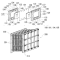
- the battery cell 100 is usually formed inside a structure called a cell stack 200 shown in the lower diagram of FIG.
- the cell stack 200 is sandwiched between two end plates 210 and 220 from both sides and is tightened by a tightening mechanism.
- the cell stack 200 includes a cell stack 120, a positive electrode 104, a diaphragm 101, and a negative electrode 105 that are stacked in this order, and both sides of the stack.
- a pair of supply / discharge plates 201 (the lower diagram in FIG. 5) is provided.
- the cell frame 120 includes a bipolar plate 121 and a frame body 122 surrounding the periphery thereof.
- one battery cell 100 is formed between the bipolar plates 121 of the adjacent cell frames 120, and the positive electrode 104 (positive electrode cell 102) of the adjacent battery cell 100 is placed on both sides of the bipolar plate 121.
- a negative electrode 105 (negative electrode cell 103) is disposed.
- Each supply / discharge plate 201 distributes each electrolytic solution between the cell stack 200 and each tank 106, 107.
- each electrolyte solution in the battery cell 100 is performed via the liquid supply manifolds 131 and 132 formed in the frame body 122 and the drainage manifolds 133 and 134.
- the positive electrode electrolyte is supplied from the liquid supply manifold 131 to the positive electrode 104 via a liquid supply guide groove 135 formed on the first surface side (the front surface side of the paper) of the frame body 122. Then, as indicated by the arrow in the upper diagram of FIG. 5, the positive electrode electrolyte passes from the lower side to the upper side of the positive electrode 104 and is discharged to the drainage manifold 133 through the drainage guide groove 137 formed in the frame body 122.
- the negative electrode electrolyte is supplied to the negative electrode 105 from the liquid supply manifold 132 through the liquid supply guide groove 136 formed on the second surface side (the back side of the paper) of the frame body 122. Then, the negative electrode electrolyte passes from the bottom to the top of the negative electrode 105 and is discharged to the drainage manifold 134 through the drainage guide groove 138 formed in the frame body 122.
- An annular seal member 140 such as an O-ring is disposed between the frame bodies 122 to suppress leakage of the electrolyte from the battery cell 100.
- a sealing member such as an O-ring made of an elastic material is soft and has a long string shape, so that it is difficult to determine the shape, and even if the O-ring is fitted in the sealing groove, the O-ring may drop from the sealing groove.
- the seal member may be displaced and fall out of the seal groove due to contact with an adjacent cell frame or a seal member provided on the adjacent cell frame when the cell frames are stacked. When the cell stack is assembled with the seal member falling off the seal groove, the electrolyte easily leaks out of the frame of the cell frame.
- an object of the present invention is to provide a redox flow battery that is easy to construct a sealing structure for an electrolytic solution and is excellent in the sealing performance of the electrolytic solution.
- a redox flow battery is a redox flow battery including a cell frame having a frame body in which a seal groove is formed, and a seal member disposed in the seal groove.
- An adhesive for fixing to the seal groove is provided, and the type A durometer hardness after curing of the adhesive is 100 or less.
- the seal member can be fixed to the seal groove with an adhesive, even if an O-ring or the like that is soft and has a long string shape and is difficult to determine the shape is used for the seal member, it prevents the seal member fitted in the seal groove from falling off the seal groove. This is because it is easy to do.
- the “curing” of the adhesive includes “solidification” of the adhesive.
- the sealing performance of the electrolyte is excellent.
- the adhesive before curing is rich in fluidity. Therefore, the adhesive before curing flows so that there is no gap between the seal groove and the seal member when the adhesive is applied to the seal groove and the seal member is brought into contact with the adhesive before curing. easy. Moreover, it is easy to suppress the formation of a gap communicating from the inside of the frame body to the outside of the frame body in the adhesive with the contact between the adhesive and the seal member. Therefore, after hardening an adhesive agent, it can suppress that electrolyte solution leaks out of a frame.
- the cured adhesive has a type A durometer hardness of 100 or less and is soft. Therefore, when the cell frame is stacked after the adhesive is cured and the seal member is fixed in the seal groove, the seal member may be compressed and deformed by the adjacent cell frame or the seal member provided in the adjacent cell frame. The cured adhesive is deformed following the deformation of the seal member. Thereby, it is easy to suppress damage such as cracking of the adhesive accompanying deformation of the seal member, and easy to suppress peeling of the seal member from the adhesive and peeling of the adhesive from the seal groove. Therefore, since it is easy to suppress that a sealing member falls from a seal groove, the leakage of electrolyte solution outside a frame can be controlled.
- the adhesive can be prevented from being damaged, the adhesive can have a function of sealing the electrolytic solution, so that the sealing property of the electrolytic solution can be easily improved.
- the type A durometer hardness after curing of the adhesive is not more than the type A durometer hardness of the seal member.
- the adhesive has the same hardness as the seal member or is softer than the seal member, and therefore easily deforms following the deformation of the seal member.
- the adhesive material is silicone resin adhesive, epoxy resin adhesive, polyurethane adhesive, acrylic adhesive, vinyl acetate adhesive, vinyl chloride adhesive And at least one material selected from an adhesive and a latex adhesive.
- the material is excellent in resistance to the electrolytic solution, so that it is easy to suppress the adhesive from being eluted by the electrolytic solution and mixed as impurities into the frame. Therefore, it is possible to suppress an increase in internal resistance and an increase in pressure loss due to impurities adhering to the electrode.
- the seal groove As one form of the redox flow battery, when the volume of the seal groove is Vg (mm 3 ), the volume of the seal member is Vs (mm 3 ), and the volume of the adhesive is Vb (mm 3 ), the seal groove
- the space factor ⁇ (Vb / Vg) ⁇ 100 ⁇ % of the adhesive in the case is ⁇ (1 ⁇ Vs / Vg) ⁇ 50 ⁇ % or more and ⁇ (1 ⁇ Vs / Vg) ⁇ 100 ⁇ % or less. It is done.
- the space factor ⁇ (Vb / Vg) ⁇ 100 ⁇ % is equal to or more than ⁇ (1-Vs / Vg) ⁇ 50 ⁇ %, the ratio of adhesive is large, so the seal member is fixed over the entire length of the seal groove. Easy to do. Therefore, it is easier to prevent leakage of the electrolyte solution over the entire length of the frame.
- the space factor ⁇ (Vb / Vg) ⁇ 100 ⁇ % is ⁇ (1 ⁇ Vs / Vg) ⁇ 100 ⁇ % or less, the ratio of the adhesive is not excessively large. Application of excessive pressure to the adhesive can be suppressed. Therefore, it is easy to suppress crushing of the adhesive after curing. In addition, it is easy to prevent early deterioration due to crushing or excessive compression of the seal member. Furthermore, since it is possible to suppress application of excessive pressure to the seal groove when the seal member is compressed, it is easy to prevent collapse of the seal groove itself.
- Embodiment 1 [Redox Flow Battery]
- the RF battery according to Embodiment 1 is similar to the conventional RF battery described with reference to FIGS. 4 and 5, and includes a cell stack 200 including a stack of cell frames and battery cells 100, and a positive electrode cell 102 of the battery cell 100. And a negative electrode electrolyte tank 107 for storing a negative electrode electrolyte to be circulated in the negative electrode cell 103. Circulation of each electrolyte is performed by pumps 112 and 113 provided in the middle of the supply conduits 108 and 109 and discharge conduits 110 and 111, respectively.
- the main feature of the RF battery according to the first embodiment is that the RF battery of the first embodiment includes an adhesive 6 (inside the one-dot chain line in FIG. 1, FIG. 2) that fixes the seal member 5 to the seal groove 48 of the cell frame 2. That is.
- an adhesive 6 a specific adhesive, that is, an adhesive having a cured type A durometer hardness of 100 or less is used. Details will be described below. The same reference numerals in the figure indicate the same names.
- the cell frame 2 includes a bipolar plate 3 and a frame 4 surrounding the periphery of the bipolar plate 3.
- the cell frame 2 includes an intermediate cell frame disposed between adjacent battery cells 100 (FIG. 5) of the stacked body and end cell frames disposed at both ends of the stacked body.
- the positive electrode 104 of one battery cell 100 and the negative electrode 105 of the other battery cell 100 are in contact with the front and back surfaces of the bipolar plate 3.
- the end cell frame one of the positive and negative electrodes of the battery cell 100 is in contact with one surface of the bipolar plate 3.
- the configuration of the front and back (positive electrode side / negative electrode side) surfaces of the cell frame 2 is the same in both the intermediate cell frame and the end cell frame.
- the bipolar plate 3 partitions adjacent battery cells 100 (FIGS. 4 and 5).
- the bipolar plate 3 is in contact with the electrodes constituting the battery cell 100.
- the shape of the bipolar plate 3 is a rectangular plate.
- the material of the bipolar plate 3 can be a material that allows current to pass but not electrolyte. In addition, a material having acid resistance and moderate rigidity is preferable.
- the material of the bipolar plate 3 is, for example, a conductive plastic formed from graphite and a polyolefin organic compound or a chlorinated organic compound. A conductive plastic in which a part of graphite is substituted with at least one of carbon black and diamond-like carbon may be used.
- Examples of the polyolefin organic compound include polyethylene, polypropylene, and polybutene.
- Examples of the chlorinated organic compound include vinyl chloride, chlorinated polyethylene, and chlorinated paraffin.
- the frame body 4 forms a region to be the battery cell 100 (FIGS. 4 and 5) on the inner side.
- the frame body 4 is provided with a liquid supply side piece 41 having a liquid supply manifold 44 for supplying an electrolytic solution to the inside of the battery cell 100 and a liquid supply side piece 41, and a drain for discharging the electrolytic solution to the outside of the battery cell 100.
- a drainage side piece 42 having a liquid manifold 45.
- the ends of the liquid supply side piece 41 and the liquid discharge side piece 42 are connected to each other by a pair of connection pieces 43 that face each other and are orthogonal to the liquid supply side piece 41 and the liquid discharge side piece 42.
- the shape of the frame body 4 is a rectangular frame shape.
- the liquid supply side piece 41 and the drainage side piece 42 constitute a long piece of a rectangular frame, and the connecting piece 43 constitutes a short piece of a rectangular frame.
- the direction in which the liquid supply side piece 41 and the drainage side piece 42 face each other is the vertical direction, and the direction orthogonal to the vertical direction is the horizontal direction, the liquid supply side piece 41 is in the vertical direction.
- the lower side and the drainage side piece 42 are positioned on the upper side in the vertical direction. That is, the flow direction of the electrolyte is a direction from the lower side in the vertical direction of the frame body 4 to the upper side in the vertical direction.
- the material of the frame 4 includes a material satisfying acid resistance, electrical insulation, and mechanical properties.
- the material of the frame 4 is, for example, various fluorine resins such as polytetrafluoroethylene, polypropylene resin, polyethylene resin, and vinyl chloride resin.
- the material of the frame 4 is a hard vinyl chloride resin.
- a seal groove 48 is formed on the outer periphery of the frame body 4 beyond both manifolds 44 and 45.
- a seal member 5 (inside the one-dot chain line in FIG. 1, FIG. 2) to be described later is fitted.
- the seal groove 48 is formed on both surfaces of the frame body 4, and is formed on the first surface side (the front side of the paper surface in FIG. 1) and on the second surface side (the back surface of the paper surface in FIG. 1). There may be no cases.
- the seal groove 48 is formed on both surfaces, the seal member 5 of the seal groove 48 is pressed by the seal member fitted into the seal groove on the second surface of the frame body of the adjacent cell frame when the cell frames 2 are stacked. To seal between the cell frames. At this time, the diaphragm 101 (FIGS. 4 and 5) is sandwiched between the seal members.
- the seal member 5 of the seal groove 48 is the frame body of the adjacent cell frame when the cell frames 2 are stacked. Is pressed by the second surface to seal between the cell frames. At this time, the diaphragm 101 (FIGS. 4 and 5) is sandwiched between the seal member 5 and the frame of the adjacent cell frame.
- the seal groove 48 is formed on the first surface side of the frame body 4 (the front side in FIG. 1) and is not formed on the second surface side of the frame body 4 (the back side in FIG. 1).
- the seal groove 48 has a single structure, but may have a double structure having an inner peripheral seal groove and an outer peripheral seal groove.
- the seal groove 48 is formed in an annular shape along the outer shape of the frame 4 (the length of each piece 41, 42, 43).
- the seal groove 48 is formed in each of the liquid supply side piece 41 and the drainage side piece 42, and is formed in the linear long straight portion 48 ⁇ / b> L in the longitudinal direction of the seal groove 48 and the connecting piece 43.
- a straight line portion 48S that is linear in the direction, and a curved portion 48C that is formed at a corner of the frame body 4 and connects the long straight portion 48L and the short straight portion 48S and curves in the longitudinal direction of the seal groove 48. It consists of
- the cross-sectional shape of the seal groove 48 is rectangular and uniform in the longitudinal direction.
- the width of the seal groove 48 is uniform in the depth direction.
- the width of the seal groove 48 can be equal to or greater than the diameter D (mm) when the seal member 5 is not compressed. That is, a gap is formed between the seal groove 48 and the seal member 5 when the seal member 5 is not compressed. If it does so, while being able to provide the adhesive agent 6 (FIG. 1 one-dot chain line circle, FIG. 2) mentioned later in the seal groove 48 easily, the seal member 5 can be easily engage
- the width of the seal groove 48 depends on the depth of the seal groove 48, the seal groove 48 may have such a size that the seal member 5 comes into contact with the side wall of the seal groove 48 when the seal member 5 is compressed. Further, the size may be such that a gap is formed between the sealing member 5 and the sealing member 5.
- the depth d (mm) of the seal groove 48 is preferably 0.5D or more although it depends on the material of the seal member 5 (FIG. 2). If the depth d of the seal groove 48 is 0.5D or more, there are not too many regions exposed from the seal groove 48 of the seal member 5, and therefore the adjacent cell frame or the seal member provided in the adjacent cell frame (hereinafter referred to as the seal member). It is easy to prevent crushing of the seal member 5 due to the adjacent member).
- the depth d of the seal groove 48 is more preferably 0.6D or more.
- the depth d of the seal groove 48 is preferably 0.9 D or less, although it depends on the material of the seal member 5.
- the depth d of the seal groove 48 is 0.9 D or less, the region exposed from the seal groove 48 of the seal member 5 can be appropriately secured, and the seal member 5 can be easily compressed by the adjacent member.
- the depth d of the seal groove 48 is more preferably 0.8D or less.
- the seal member 5 prevents leakage of the electrolyte supplied to the battery cell 100 (FIGS. 4 and 5) to the outside of the frame body 4 (an enlarged view of FIG. 1). Specifically, the seal member 5 is disposed in the seal groove 48, and when the cell frame 2 is stacked as described above, the seal member fitted into the seal groove on the second surface of the frame body in the adjacent cell frame, Alternatively, it is pressed against one of the second surfaces of the frame bodies of the adjacent cell frames and elastically deforms to seal between the cell frames 2.
- the seal member 5 an O-ring can be used as the seal member 5.
- the cross-sectional shape of the seal member 5 is circular when not compressed.
- the cross-sectional shape of the seal member 5 is the same circular shape as that at the time of non-compression.
- the material of the seal member 5 includes an elastic material having excellent acid resistance.
- rubbers such as ethylene-propylene-diene rubber (EPDM), fluorine rubber, and silicone rubber are suitable.
- the type A durometer hardness of the seal member 5 can be set to 90 or less, for example. If the type A durometer hardness of the seal member 5 is 90 or less, the seal member 5 is soft. Therefore, the seal member 5 is elastically deformed and the cell frame 2 is easily sealed.
- the type A durometer hardness of the seal member 5 can be set to 50 or more, for example. If the type A durometer hardness of the seal member 5 is 50 or more, the seal member 5 has moderate elasticity without being excessively soft.
- the type A durometer hardness is a value based on "vulcanized rubber and thermoplastic rubber-how to obtain hardness-part 3: durometer hardness JIS K 6253-3 (2012)”. This also applies to the type A durometer hardness of the adhesive 6 described later.
- the adhesive 6 fixes the seal member 5 to the seal groove 48 (FIG. 1 within a one-dot chain line circle, FIG. 2). By this fixing, a sealing structure of the electrolytic solution in the cell frame 2 is constructed, and leakage of the electrolytic solution to the outside of the frame body 4 is suppressed.
- the adhesive 6 is made of a soft material having a type A durometer hardness of 100 or less after curing. Then, the adhesive 6 can easily follow the deformation of the seal member 5 when the seal member 5 is compressed by the adjacent member. Therefore, it is easy to suppress damage such as cracking of the adhesive 6 due to deformation of the seal member 5, and it is easy to suppress peeling of the seal member 5 from the adhesive 6 and peeling of the adhesive 6 from the seal groove 48.
- the difference between the type A durometer hardness after curing of the adhesive 6 and the type A durometer hardness of the seal member 5 Is preferably as small as possible. Then, since the adhesive 6 easily follows the deformation of the seal member 5, it is easy to suppress damage to the adhesive 6 accompanying the deformation of the seal member 5.
- the difference between the type A durometer hardness after curing of the adhesive 6 and the type A durometer hardness of the seal member 5 is preferably 20 or less, more preferably 10 or less, and particularly preferably 5 or less.
- the type A durometer hardness after curing of the adhesive 6 is preferably as small as possible, and particularly preferably not more than the type A durometer hardness of the seal member 5. Then, since the adhesive 6 is easily deformed as easily as the seal member 5 or is deformed more easily than the seal member 5, damage to the adhesive 6 due to the deformation of the seal member 5 can be further suppressed.
- the type A durometer hardness after curing of the adhesive 6 is more preferably 90 or less, further preferably 70 or less and 60 or less, and particularly preferably 50 or less and 40 or less.
- the type A durometer hardness after curing of the adhesive 6 is practically preferably 20 or more.
- the material of the adhesive 6 is selected from a silicone resin adhesive, an epoxy resin adhesive, a polyurethane adhesive, an acrylic adhesive, a vinyl acetate adhesive, a vinyl chloride adhesive, and a latex adhesive. It is preferable that it is 1 or more types of materials. Among these materials, the material of the adhesive 6 is particularly preferably at least one material selected from a silicone resin adhesive and an epoxy resin adhesive. Since the silicone resin adhesive and the epoxy resin adhesive are excellent in resistance to the electrolytic solution, it is easy to suppress the adhesive from being eluted by the electrolytic solution and mixed as impurities into the frame. Therefore, an increase in internal resistance and an increase in pressure loss due to the adhesion of impurities to the electrode electrodes 104 and 105 (FIG.
- the material of the adhesive 6 is preferably a material that cures (solidifies) at room temperature. If it does so, compared with a thermosetting adhesive agent, a thermal history will not be applied to the frame 4 (cell frame 2). Moreover, it is excellent in workability compared with a thermoplastic adhesive. This is because the adhesive 6 does not have to be melted by heating in order to apply the adhesive 6 to the seal groove 48, and it is not necessary to cool the adhesive to cure.
- the material of the adhesive 6 is preferably a material having a relatively long curing (solidification) time. For example, the curing (solidification) time of the adhesive 6 is preferably 1 minute or longer. By doing so, there is a sufficient working time, and it is easy to perform the work of fitting the seal member 5 into the seal groove 48 after applying the adhesive 6 to the seal groove 48.
- the space factor of the adhesive 6 in the seal groove 48 ⁇ (Vb / Vg) ⁇ 100 ⁇ % is preferably ⁇ (1 ⁇ Vs / Vg) ⁇ 100 ⁇ % or less. If the space factor ⁇ (Vb / Vg) ⁇ 100 ⁇ % is ⁇ (1-Vs / Vg) ⁇ 100 ⁇ % or less, the ratio of the adhesive 6 is not excessively large, so the seal member 5 is compressed. At this time, it is possible to suppress application of excessive pressure to the adhesive 6. Therefore, it is easy to suppress the collapse of the adhesive 6 after curing.
- the space factor ⁇ (Vb / Vg) ⁇ 100 ⁇ % is more preferably ⁇ (1 ⁇ Vs / Vg) ⁇ 90 ⁇ % or less, and particularly preferably ⁇ (1 ⁇ Vs / Vg) ⁇ 80 ⁇ % or less.
- the space factor ⁇ (Vb / Vg) ⁇ 100 ⁇ % is preferably not less than ⁇ (1 ⁇ Vs / Vg) ⁇ 50 ⁇ %.
- the space factor ⁇ (Vb / Vg) ⁇ 100 ⁇ % is ⁇ (1 ⁇ Vs / Vg) ⁇ 50 ⁇ % or more, the ratio of the adhesive 6 is large. It is easy to fix over. Therefore, it is easier to prevent leakage of the electrolyte solution over the entire length of the frame body 4.
- the space factor ⁇ (Vb / Vg) ⁇ 100 ⁇ % is more preferably ⁇ (1 ⁇ Vs / Vg) ⁇ 60 ⁇ % or more, and particularly preferably ⁇ (1 ⁇ Vs / Vg) ⁇ 70 ⁇ % or more.
- the space factor ⁇ (Vb / Vg) ⁇ 100 ⁇ % is the above lower limit at at least one of the locations where the adhesive 6 is formed. It is preferable that it is above or below the above upper limit, and more preferably above the above lower limit or below the above upper limit at all locations where the adhesive 6 is formed.
- the space factor ⁇ (Vb / Vg) ⁇ 100 ⁇ % is not uniform, the space factor ⁇ (Vb / Vg) ⁇ 100 ⁇ %
- the average value over the entire length of the seal groove 48 is preferably not less than the above lower limit or not more than the above upper limit.
- the adhesive 6 is not formed over the entire length of the seal groove 48 and the space factor ⁇ (Vb / Vg) ⁇ 100 ⁇ % is not uniform at each location where the adhesive 6 is formed, the adhesive It is preferable that the average value of the space factor ⁇ (Vb / Vg) ⁇ 100 ⁇ % in at least one place where 6 is formed is not less than the above lower limit or not more than the above upper limit, and each of the adhesives 6 formed It is more preferable that all the average values of the space factor ⁇ (Vb / Vg) ⁇ 100 ⁇ % at the locations are in the above range.
- the adhesive 6 may be formed at least at one place along the entire length of the seal groove 48. The more the adhesive 6 is formed, the easier it is to prevent the seal member 5 from falling off the seal groove 48. In the case where the adhesive 6 is formed at a plurality of locations along the entire length of the seal groove 48, the formation location of the adhesive 6 is preferably at least one of an opposing position and a diagonal position in the seal groove 48.
- the adhesive 6 can be formed at least (1) four curved portions 48C, (2) a pair of long straight portions 48L, or (3) a pair of short straight portions 48S.
- the adhesive 6 may be provided in a plurality of locations in each of (1) four curved portions 48C, (2) a pair of long straight portions 48L, or (3) a pair of short straight portions 48S.
- the locations where the adhesive 6 is formed are at least four curved portions 48C, it is effective in preventing the seal member 5 from coming off from the seal groove 48. This is because the curved portion 48C is more likely to drop off the sealing member 5 than the long straight portion 48L and the short straight portion 48S.
- the locations where the adhesive 6 is formed include two or more patterns selected from (1) four curved portions 48C, (2) a pair of long straight portions 48L, and (3) a pair of short straight portions 48S. In addition, it is preferable that all the three patterns (1) to (3) are provided. Since the seal member 5 can be fixed to the seal groove 48 by the respective pieces 41, 42, 43 if the formation place of the adhesive 6 is all of the three patterns (1) to (3), the seal of the seal member 5 This is more effective for preventing the groove 48 from falling off.
- each adhesive agent 6 may be provided in a line shape or a dot shape.
- the distance between the adjacent adhesives 6 in the longitudinal direction of the seal groove 48 can prevent the seal member 5 from falling off, and the application work of the adhesive 6 is difficult to be complicated.
- the intervals in the longitudinal direction of the seal grooves 48 of the adjacent adhesives 6 may be equal intervals over the entire length of the seal grooves 48, or may be equal intervals in each of the portions 48C, 48L, and 48S.
- the adhesive 6 may be provided in series over the entire length of the seal groove 48.
- the seal member 5 can be fixed over the entire length of the seal groove 48, it is particularly effective in preventing the seal member 5 from falling off the seal groove 48.
- the adhesive 6 is provided over the entire length of the seal groove 48, the electrolyte 6 can be sealed with the adhesive 6 over the entire length of the seal groove 48, so that the sealing performance of the electrolyte can be improved.
- the adhesive 6 is formed at all locations of the long straight portion 48L, the short straight portion 48S, and the curved portion 48C.
- the intervals in the longitudinal direction of the seal grooves 48 of the adjacent adhesives 6 are equal in each of the portions 48C, 48L, and 48S.
- the liquid supply side piece 41 is formed with a liquid supply guide groove 46 that leads between the liquid supply manifold 44 and the bipolar plate 3 and guides the electrolytic solution from the liquid supply manifold 44 to the bipolar plate 3 (FIG. 1).
- the drainage side piece 42 is formed with a drainage guide groove 47 that leads between the drainage manifold 45 and the bipolar plate 3 and guides the electrolyte from the bipolar plate 3 to the drainage manifold 45.
- Both the guide grooves 46 and 47 are covered with a protective plate (not shown) made of plastic when the laminate is constructed.
- the seal member fitted into the manifold seal grooves 44a and 45a can be fixed to the manifold seal grooves 44a and 45a with the same adhesive (not shown) as the above-described adhesive 6 that fixes the seal member 5 to the seal groove 48. preferable. If it does so, the leakage of the electrolyte solution from each manifold 44 and 45 can be suppressed.
- seal member 5 can be fixed to the seal groove 48 by the adhesive 6, the seal member 5 fitted in the seal groove 48 is sealed even if an O-ring or the like that is soft and has a long string shape and is difficult to determine the shape is used as the seal member 5. It is because it is easy to suppress dropping from the groove 48.
- the adhesive after curing has a type A durometer hardness of 100 or less and is soft, the adhesive before curing is rich in fluidity. Therefore, the adhesive 6 before curing does not cause a gap between the seal groove 48 and the seal member 5 when the adhesive 6 is applied to the seal groove 48 and the seal member 5 is brought into contact before the cure. It is easy to flow. Thereby, it is easy to suppress the formation of a gap communicating from the inside of the frame body 4 to the outside of the frame body 4 in the adhesive 6 with the contact between the adhesive 6 and the seal member 5. Therefore, it can suppress that electrolyte solution leaks out of the frame 4 from the clearance gap.
- the cured adhesive 6 has a type A durometer hardness of 100 or less and is soft.
- the seal member 5 is compressed to the adjacent cell frame or the seal member provided on the adjacent cell frame. Even when the adhesive 6 is deformed, the cured adhesive 6 deforms following the deformation of the seal member 5. Thereby, it is easy to suppress damage to the adhesive 6 due to deformation of the seal member 5, and it is easy to suppress peeling of the seal member 5 from the adhesive 6 and peeling of the adhesive 6 from the seal groove 48. Therefore, it is easy to suppress the sealing member 5 from dropping from the sealing groove 48, so that leakage of the electrolytic solution to the outside of the frame body 4 can be suppressed. Thus, since the damage of the adhesive agent 6 can be suppressed, the adhesive agent 6 can have a function of sealing the electrolytic solution, and thus it is easy to improve the sealing performance of the electrolytic solution.
- Test Example 1 Using the liquid leakage test jig 300 shown in FIG. 3, the difference in the amount of water leakage depending on the presence or absence of the adhesive 6 that fixes the seal member 5 to the seal groove 48 was examined.
- the liquid leakage test jig 300 makes water easier to leak than a cell stack 200 of a general RF battery (see FIG. 5) so that the difference in the amount of water leakage can be easily understood for convenience.
- a liquid leakage test jig 300 includes one cell frame equivalent member 310, one sheet supply / discharge plate equivalent member 320, one seal member 5 (cross-sectional view on the right in FIG. 3), and an adhesive. Agent 6 is provided. Sample No. In the liquid leakage test jig 300 of 1-1, the seal member 5 is fixed to the seal groove 48 of the cell frame equivalent member 310 with the adhesive 6, and the supply / discharge plate equivalent member 320 is laminated on the cell frame equivalent member 310. Configured.
- the cell frame equivalent member 310 is a member simulating the cell frame 2 described in the first embodiment, and here, it is formed of a transparent rectangular flat plate.
- a rectangular recess 311 is formed at the center of the surface of the cell frame equivalent member 310 facing the supply / discharge plate equivalent member 320, and the recess 311 is formed on the outer periphery of the recess 311 along the outer shape of the cell frame equivalent member 310.
- a single annular seal groove 48 is formed around the periphery. The seal member 5 is fitted in the seal groove 48.
- the supply / discharge plate equivalent member 320 is a supply / discharge plate 201 (see FIG. 5) for supplying / discharging each electrode electrolyte between the battery cell 100 and each electrode electrolyte tank 106, 107 (see FIG. 4) in the RF battery. This is a simulated member, and here it is formed of a transparent rectangular plate.
- the size of the supply / discharge plate equivalent member 320 is the same as that of the cell frame equivalent member 310.
- the supply / discharge plate equivalent member 320 performs supply of water to the recess 311 of the cell frame equivalent member 310 and discharge of water from the recess 311.
- the supply hole 321 for supplying water to the concave portion 311 penetrating through the front and back, and the water supplied to the concave portion 311 are discharged.
- a discharge hole 323 is formed.
- a supply pipe 322 and a discharge pipe 324 attached to the supply hole 321 and the discharge hole 323 are provided on the side surface of the supply / discharge plate equivalent member 320 opposite to the cell frame equivalent member 310.
- Water is supplied from the supply pipe 322 to the recess 311 via the supply hole 321, and the water supplied to the recess 311 is discharged from the discharge hole 323 to the outside of the liquid leakage test jig 300 via the discharge pipe 324.
- the seal member 5 is fitted into the seal groove 48 to suppress water leakage from the interface between the cell frame equivalent member 310 and the supply / discharge plate equivalent member 320 to the outside of the liquid leakage test jig 300.
- an O-ring having a type A durometer hardness of 70 was used as the seal member 5.
- the adhesive 6 fixes the seal member 5 to the seal groove 48.
- a silicone-based adhesive having a type A durometer hardness of 60 after curing (silicone sealant KE-40RTV manufactured by Shin-Etsu Chemical Co., Ltd.) was used as the adhesive 6.
- the space factor ⁇ (Vb / Vg) ⁇ 100 ⁇ % of the adhesive 6 in the seal groove 48 was set to ⁇ (1 ⁇ Vs / Vg) ⁇ 50 ⁇ %.
- Sample No. 1-2 Sample No. The liquid leak test jig 300 of 1-2 uses a silicone adhesive having a type A durometer hardness of 28 after curing (silicone sealant KE-42 manufactured by Shin-Etsu Chemical Co., Ltd.) as the adhesive 6 and seals it. Except for the fact that the space factor ⁇ (Vb / Vg) ⁇ 100 ⁇ % of the adhesive to be fixed in the groove 48 was changed to ⁇ (1 ⁇ Vb / Vg) ⁇ 70 ⁇ %, the sample No. Same as 1-1.
- Sample No. 1100 Sample No. The liquid leak test jig 300 of 1-100 is the same as the sample No. 1 except that an adhesive for fixing the seal member 5 to the seal groove 48 is not used. Same as 1-1. That is, sample no. The seal member 5 of the 1-100 liquid leakage test jig 300 is only fitted in the seal groove 48.
- Sample No. The amount of water leakage in the liquid leakage test jig 300 of 1-2 is shown in Sample No. It was even smaller than the 1-1 liquid leakage test jig 300. Accordingly, an adhesive having a smaller type A durometer hardness after curing is used, and the space factor ⁇ (Vb / Vg) ⁇ 100 ⁇ % of the adhesive 6 in the seal groove 48 is reduced to ⁇ (1 ⁇ Vb / Vg) ⁇ 70. ⁇ %, It can be seen that the water sealing property is further improved.
- Test Example 2 A cell stack 2 described with reference to FIGS. 1 and 2 is used to assemble a cell stack similar to the cell stack 200 described with reference to FIG. Was disassembled and the fixing state of the seal member 5 to the seal groove 48 was confirmed.
- a cell stack was assembled by stacking a plurality of cell frames 2.
- the number of cells is five.
- the adhesive 6 is applied to the seal groove 48, the seal member 5 is fitted into the seal groove 48, the adhesive 6 is cured, and the seal member 5 is sealed to the seal groove 48. It went after fixing to.
- Sample No. 1 of Test Example 1 is applied to the seal member 5 and the adhesive 6. 1-1, and the space factor of the adhesive 6 is the same as that of Sample No. 1 of Test Example 1. Same as 1-1.
- the cell stack was disassembled and the seal groove 48 of the cell frame 2 was visually confirmed.
- the seal member 5 was not dropped from the seal groove 48 and was firmly fixed by the adhesive 6. Therefore, it can be seen that the sealing member 5 can be prevented from falling off the sealing groove 48 by fixing the sealing member 5 to the sealing groove 48 with the adhesive 6 having a soft hardness after curing.
- Test Example 3 Sample No. 1 of Test Example 1 is applied to the seal member 5 and the adhesive 6. The same space as that of 1-2 was used, and the space factor of the adhesive 6 was the sample No. A cell stack was assembled in the same manner as in Test Example 2 except that it was the same as 1-1. In the same manner as in Test Example 2, after the electrolytic solution was circulated and charged and discharged, the cell stack was disassembled and the fixing state of the seal member 5 to the seal groove 48 was visually confirmed. The seal member 5 was not dropped from the seal groove 48 and was firmly fixed by the adhesive 6. Therefore, also in Test Example 3, it can be seen that the seal member 5 can be prevented from falling off the seal groove 48.
Landscapes
- Life Sciences & Earth Sciences (AREA)
- Engineering & Computer Science (AREA)
- Manufacturing & Machinery (AREA)
- Sustainable Development (AREA)
- Sustainable Energy (AREA)
- Chemical & Material Sciences (AREA)
- Chemical Kinetics & Catalysis (AREA)
- Electrochemistry (AREA)
- General Chemical & Material Sciences (AREA)
- Fuel Cell (AREA)
Abstract
A redox flow battery which comprises: a cell frame having a frame body that is provided with a sealing groove; and a sealing member that is arranged in the sealing groove. This redox flow battery comprises an adhesive that affixes the sealing member to the sealing groove; and the adhesive has a type A durometer hardness of 100 or less after curing. It is preferable that the type A durometer hardness of the adhesive after curing is not more than the type A durometer hardness of the sealing member.
Description
本発明は、レドックスフロー電池に関する。
本出願は、2016年2月29日出願の日本出願第2016-038080号に基づく優先権を主張し、前記日本出願に記載された全ての記載内容を援用するものである。 The present invention relates to a redox flow battery.
This application claims priority based on Japanese Patent Application No. 2016-038080 filed on Feb. 29, 2016, and incorporates all the content described in the Japanese application.
特許文献1のレドックスフロー電池(RF電池)は、内周シール溝及び外周シール溝がフレーム(枠体)の両面にそれぞれ対向する位置に設けられ、内周シール溝、外周シール溝のそれぞれに内周シール、外周シールが配置されている。この内周シール及び外周シールにはOリングが使用されている。そして、積層した複数のセルフレームをその両側から挟むエンドプレートを締め付けて押圧することで、内周シールと外周シールとが隔膜を圧接してフレーム同士の間からセルの電解液の漏洩を防止している。
In the redox flow battery (RF battery) of Patent Document 1, an inner peripheral seal groove and an outer peripheral seal groove are provided at positions facing both surfaces of a frame (frame body), respectively, and an inner peripheral seal groove and an outer peripheral seal groove are provided in each of A peripheral seal and an outer peripheral seal are arranged. O-rings are used for the inner and outer peripheral seals. And by tightening and pressing the end plates that sandwich the stacked cell frames from both sides, the inner and outer seals press against the diaphragm to prevent leakage of cell electrolyte from between the frames. ing.
本発明の一態様に係るレドックスフロー電池は、シール溝が形成された枠体を有するセルフレームと、シール溝に配置されたシール部材とを備えるレドックスフロー電池であって、シール部材をシール溝に固定する接着剤を備え、接着剤の硬化後のタイプAデュロメータ硬さが100以下である。
A redox flow battery according to an aspect of the present invention is a redox flow battery including a cell frame having a frame body in which a seal groove is formed, and a seal member disposed in the seal groove, wherein the seal member is used as the seal groove. An adhesive for fixing is provided, and the type A durometer hardness after curing of the adhesive is 100 or less.
太陽光発電や風力発電といった自然エネルギー由来の電力を蓄電する大容量の蓄電池の一つにレドックスフロー電池(RF電池)がある。図4のRF電池の動作原理図に示すように、RF電池1は、代表的には、交流/直流変換器を介して発電部(例えば、太陽光発電装置や風力発電装置、その他一般の発電所など)と負荷(需要家など)との間に接続され、発電部で発電した電力を充電して蓄え、蓄えた電力を放電して負荷に供給する。
A redox flow battery (RF battery) is one of large-capacity storage batteries that store electric power derived from natural energy such as solar power generation and wind power generation. As shown in the operation principle diagram of the RF battery in FIG. 4, the RF battery 1 typically includes a power generation unit (for example, a solar power generation device, a wind power generation device, or other general power generation via an AC / DC converter). The power is generated and stored in the power generation unit and stored, and the stored power is discharged and supplied to the load.
RF電池1は、水素イオンを透過させる隔膜101で正極セル102と負極セル103とに分離された電池セル100を備える。正極セル102には正極電極104が内蔵され、正極電解液を貯留する正極電解液タンク106が供給導管108、排出導管110を介して接続されている。同様に、負極セル103には負極電極105が内蔵され、負極電解液を貯留する負極電解液タンク107が供給導管109、排出導管111を介して接続されている。各極電解液は、各供給導管108,109の途中に設けられたポンプ112,113により各供給導管108、109から各極セル102、103に供給され、各極セル102、103から各排出導管110、111を流通して各極タンク106、107に排出されることで各極セル102、103に循環される。RF電池1は、こうして電解液を循環して、正極電解液に含まれるイオンと負極電解液に含まれるイオンの酸化還元電位の差を利用して充放電を行う。図4では、各極電解液に含まれるイオンとしてバナジウムイオンを示しており、実線矢印は充電、破線矢印は放電を意味する。
The RF battery 1 includes a battery cell 100 separated into a positive electrode cell 102 and a negative electrode cell 103 by a diaphragm 101 that transmits hydrogen ions. A positive electrode 104 is built in the positive electrode cell 102, and a positive electrode electrolyte tank 106 that stores a positive electrode electrolyte is connected via a supply conduit 108 and a discharge conduit 110. Similarly, a negative electrode 105 is built in the negative electrode cell 103, and a negative electrode electrolyte tank 107 that stores a negative electrode electrolyte is connected via a supply conduit 109 and a discharge conduit 111. Each electrolyte solution is supplied to each electrode cell 102, 103 from each supply conduit 108, 109 by each pump 112, 113 provided in the middle of each supply conduit 108, 109, and each discharge conduit from each electrode cell 102, 103. 110 and 111 are circulated to each electrode cell 102 and 103 by being discharged to each electrode tank 106 and 107. The RF battery 1 circulates the electrolytic solution in this way, and performs charging / discharging using the difference between the redox potentials of the ions contained in the positive electrode electrolyte and the ions contained in the negative electrode electrolyte. In FIG. 4, vanadium ions are shown as ions contained in each electrode electrolyte, and solid arrows indicate charging and broken arrows indicate discharging.
電池セル100は、通常、図5下図に示すセルスタック200と呼ばれる構造体の内部に形成される。セルスタック200は、その両側から2枚のエンドプレート210、220で挟み込んで締付機構により締め付けられている。セルスタック200は、図5上図に示すように、セルフレーム120、正極電極104、隔膜101、及び負極電極105を、この順番で積層することで形成される積層体と、積層体の両側に配置される一対の給排板201(図5下図)とを備える。セルフレーム120は、双極板121とその周縁を囲む枠体122とを備える。この構成の場合、隣接するセルフレーム120の双極板121の間に一つの電池セル100が形成され、双極板121を挟んで表裏に、隣り合う電池セル100の正極電極104(正極セル102)と負極電極105(負極セル103)とが配置される。各給排板201は、セルスタック200と各タンク106、107との間での各電解液の流通を行う。
The battery cell 100 is usually formed inside a structure called a cell stack 200 shown in the lower diagram of FIG. The cell stack 200 is sandwiched between two end plates 210 and 220 from both sides and is tightened by a tightening mechanism. As shown in the upper diagram of FIG. 5, the cell stack 200 includes a cell stack 120, a positive electrode 104, a diaphragm 101, and a negative electrode 105 that are stacked in this order, and both sides of the stack. A pair of supply / discharge plates 201 (the lower diagram in FIG. 5) is provided. The cell frame 120 includes a bipolar plate 121 and a frame body 122 surrounding the periphery thereof. In the case of this configuration, one battery cell 100 is formed between the bipolar plates 121 of the adjacent cell frames 120, and the positive electrode 104 (positive electrode cell 102) of the adjacent battery cell 100 is placed on both sides of the bipolar plate 121. A negative electrode 105 (negative electrode cell 103) is disposed. Each supply / discharge plate 201 distributes each electrolytic solution between the cell stack 200 and each tank 106, 107.
電池セル100内の各極電解液の流通は、枠体122に形成される給液マニホールド131、132と、排液マニホールド133、134とを介して行われる。正極電解液は、給液マニホールド131から枠体122の第1面側(紙面表側)に形成される給液ガイド溝135を介して正極電極104に供給される。そして、図5上図の矢印に示すように正極電解液は正極電極104の下から上へ通り、枠体122に形成される排液ガイド溝137を介して排液マニホールド133に排出される。同様に、負極電解液は、給液マニホールド132から枠体122の第2面側(紙面裏側)に形成される給液ガイド溝136を介して負極電極105に供給される。そして、負極電解液は負極電極105の下から上へ通り、枠体122に形成される排液ガイド溝138を介して排液マニホールド134に排出される。各枠体122間には、Oリングなどの環状のシール部材140が配置され、電池セル100からの電解液の漏洩を抑制している。
The circulation of each electrolyte solution in the battery cell 100 is performed via the liquid supply manifolds 131 and 132 formed in the frame body 122 and the drainage manifolds 133 and 134. The positive electrode electrolyte is supplied from the liquid supply manifold 131 to the positive electrode 104 via a liquid supply guide groove 135 formed on the first surface side (the front surface side of the paper) of the frame body 122. Then, as indicated by the arrow in the upper diagram of FIG. 5, the positive electrode electrolyte passes from the lower side to the upper side of the positive electrode 104 and is discharged to the drainage manifold 133 through the drainage guide groove 137 formed in the frame body 122. Similarly, the negative electrode electrolyte is supplied to the negative electrode 105 from the liquid supply manifold 132 through the liquid supply guide groove 136 formed on the second surface side (the back side of the paper) of the frame body 122. Then, the negative electrode electrolyte passes from the bottom to the top of the negative electrode 105 and is discharged to the drainage manifold 134 through the drainage guide groove 138 formed in the frame body 122. An annular seal member 140 such as an O-ring is disposed between the frame bodies 122 to suppress leakage of the electrolyte from the battery cell 100.
《本開示が解決しようとする課題》
電解液のシール構造を構築し易く、電解液のシール性を向上することが望まれている。弾性材料からなるOリングなどのシール部材は、柔らかい上に長い紐状なので形状が定まり難く、Oリングをシール溝に嵌め込んでもOリングがシール溝から脱落する虞がある。特に、シール部材は、セルフレームを積層した際の隣り合うセルフレーム又は隣接するセルフレームに設けられたシール部材との接触などにより、ずれてシール溝から脱落する虞がある。シール部材がシール溝から脱落したままセルスタックが組み立てられると、電解液がセルフレームの枠体外に漏洩し易くなる。 << Problems to be solved by this disclosure >>
It is easy to construct a sealing structure for an electrolytic solution, and it is desired to improve the sealing performance of the electrolytic solution. A sealing member such as an O-ring made of an elastic material is soft and has a long string shape, so that it is difficult to determine the shape, and even if the O-ring is fitted in the sealing groove, the O-ring may drop from the sealing groove. In particular, there is a possibility that the seal member may be displaced and fall out of the seal groove due to contact with an adjacent cell frame or a seal member provided on the adjacent cell frame when the cell frames are stacked. When the cell stack is assembled with the seal member falling off the seal groove, the electrolyte easily leaks out of the frame of the cell frame.
上記事情に鑑みて、電解液のシール構造を構築し易くて、電解液のシール性に優れるレドックスフロー電池を提供することを目的とする。
In view of the above circumstances, an object of the present invention is to provide a redox flow battery that is easy to construct a sealing structure for an electrolytic solution and is excellent in the sealing performance of the electrolytic solution.
《本開示の効果》
本開示によれば、電解液のシール構造を構築し易くて、電解液のシール性に優れるレドックスフロー電池を提供することができる。 <Effects of the present disclosure>
According to the present disclosure, it is possible to provide a redox flow battery that is easy to construct a sealing structure of an electrolytic solution and is excellent in sealing performance of the electrolytic solution.
《本発明の実施形態の説明》
最初に本発明の実施態様の内容を列記して説明する。 << Description of Embodiments of the Present Invention >>
First, the contents of the embodiments of the present invention will be listed and described.
最初に本発明の実施態様の内容を列記して説明する。 << Description of Embodiments of the Present Invention >>
First, the contents of the embodiments of the present invention will be listed and described.
(1)本発明の一態様に係るレドックスフロー電池は、シール溝が形成された枠体を有するセルフレームと、シール溝に配置されたシール部材とを備えるレドックスフロー電池であって、シール部材をシール溝に固定する接着剤を備え、接着剤の硬化後のタイプAデュロメータ硬さが100以下である。
(1) A redox flow battery according to an aspect of the present invention is a redox flow battery including a cell frame having a frame body in which a seal groove is formed, and a seal member disposed in the seal groove. An adhesive for fixing to the seal groove is provided, and the type A durometer hardness after curing of the adhesive is 100 or less.
上記の構成によれば、電解液のシール構造を構築し易い。接着剤によりシール部材をシール溝に固定できるため、柔らかくて長い紐状で形状の定まり難いOリングなどをシール部材に用いても、シール溝に嵌め込んだシール部材のシール溝からの脱落を抑制し易いからである。なお、接着剤の「硬化」には、接着剤の「固化」も含まれるものとする。
According to the above configuration, it is easy to construct a sealing structure for the electrolytic solution. Since the seal member can be fixed to the seal groove with an adhesive, even if an O-ring or the like that is soft and has a long string shape and is difficult to determine the shape is used for the seal member, it prevents the seal member fitted in the seal groove from falling off the seal groove. This is because it is easy to do. The “curing” of the adhesive includes “solidification” of the adhesive.
また、上記の構成によれば、電解液のシール性に優れる。
Moreover, according to the above configuration, the sealing performance of the electrolyte is excellent.
硬化前の接着剤は流動性に富む。そのため、硬化前の接着剤は、接着剤をシール溝に塗布して硬化前の接着剤にシール部材を接触させた際、シール溝内とシール部材との間に隙間が生じないように流動し易い。また、接着剤とシール部材との接触に伴って接着剤内に枠体内側から枠体外側へ連通する隙間が形成されることを抑制し易い。従って、接着剤を硬化させた後、電解液が枠体外へ漏洩することを抑制できる。
The adhesive before curing is rich in fluidity. Therefore, the adhesive before curing flows so that there is no gap between the seal groove and the seal member when the adhesive is applied to the seal groove and the seal member is brought into contact with the adhesive before curing. easy. Moreover, it is easy to suppress the formation of a gap communicating from the inside of the frame body to the outside of the frame body in the adhesive with the contact between the adhesive and the seal member. Therefore, after hardening an adhesive agent, it can suppress that electrolyte solution leaks out of a frame.
硬化後の接着剤は、タイプAデュロメータ硬さが100以下であり柔らかい。そのため、接着剤硬化してシール溝にシール部材が固定された後にセルフレームを積層した際、シール部材が隣接するセルフレーム又は隣接するセルフレームに設けられたシール部材に圧縮されて変形しても、硬化後の接着剤は、そのシール部材の変形に追従して変形させられる。それにより、シール部材の変形に伴う接着剤の割れなどの損傷を抑制し易く、シール部材の接着剤からの剥離や接着剤のシール溝からの剥離を抑制し易い。従って、シール部材がシール溝から脱落することを抑制し易いため、電解液の枠体外への漏洩を抑制できる。
The cured adhesive has a type A durometer hardness of 100 or less and is soft. Therefore, when the cell frame is stacked after the adhesive is cured and the seal member is fixed in the seal groove, the seal member may be compressed and deformed by the adjacent cell frame or the seal member provided in the adjacent cell frame. The cured adhesive is deformed following the deformation of the seal member. Thereby, it is easy to suppress damage such as cracking of the adhesive accompanying deformation of the seal member, and easy to suppress peeling of the seal member from the adhesive and peeling of the adhesive from the seal groove. Therefore, since it is easy to suppress that a sealing member falls from a seal groove, the leakage of electrolyte solution outside a frame can be controlled.
接着剤の損傷を抑制できることで、接着剤は電解液をシールする機能を有することができるため、電解液のシール性を高め易い。
Since the adhesive can be prevented from being damaged, the adhesive can have a function of sealing the electrolytic solution, so that the sealing property of the electrolytic solution can be easily improved.
(2)上記レドックスフロー電池の一形態として、接着剤の硬化後のタイプAデュロメータ硬さが、シール部材のタイプAデュロメータ硬さ以下であることが挙げられる。
(2) As one form of the redox flow battery, it is mentioned that the type A durometer hardness after curing of the adhesive is not more than the type A durometer hardness of the seal member.
上記の構成によれば、シール部材の変形に伴う接着剤の損傷をより一層抑制し易い。接着剤は、シール部材と同等の硬さであるか、シール部材よりも柔らかいため、シール部材の変形に追従して変形し易いからである。
According to the above configuration, it is easier to further suppress the damage to the adhesive accompanying the deformation of the seal member. This is because the adhesive has the same hardness as the seal member or is softer than the seal member, and therefore easily deforms following the deformation of the seal member.
(3)上記レドックスフロー電池の一形態として、接着剤の材質は、シリコーン樹脂系接着剤、エポキシ樹脂系接着剤、ポリウレタン系接着剤、アクリル系接着剤、酢酸ビニル系接着剤、塩化ビニル系接着剤、及びラテックス系接着剤の中から選択される1種以上の材質であることが挙げられる。
(3) As one form of the redox flow battery, the adhesive material is silicone resin adhesive, epoxy resin adhesive, polyurethane adhesive, acrylic adhesive, vinyl acetate adhesive, vinyl chloride adhesive And at least one material selected from an adhesive and a latex adhesive.
上記の構成によれば、電池性能の低下を抑制し易い。上記材質は電解液に対する耐性に優れるため、接着剤が電解液により溶出して不純物として枠体内に混入することを抑制し易いからである。そのため、不純物の電極への付着などに伴う内部抵抗の上昇や圧力損失の増加を抑制できる。
According to the above configuration, it is easy to suppress a decrease in battery performance. This is because the material is excellent in resistance to the electrolytic solution, so that it is easy to suppress the adhesive from being eluted by the electrolytic solution and mixed as impurities into the frame. Therefore, it is possible to suppress an increase in internal resistance and an increase in pressure loss due to impurities adhering to the electrode.
(4)上記レドックスフロー電池の一形態として、シール溝の体積をVg(mm3)、シール部材の体積をVs(mm3)、接着剤の体積をVb(mm3)とするとき、シール溝における接着剤の占積率{(Vb/Vg)×100}%は、{(1-Vs/Vg)×50}%以上{(1-Vs/Vg)×100}%以下であることが挙げられる。
(4) As one form of the redox flow battery, when the volume of the seal groove is Vg (mm 3 ), the volume of the seal member is Vs (mm 3 ), and the volume of the adhesive is Vb (mm 3 ), the seal groove The space factor {(Vb / Vg) × 100}% of the adhesive in the case is {(1−Vs / Vg) × 50}% or more and {(1−Vs / Vg) × 100}% or less. It is done.
占積率{(Vb/Vg)×100}%が{(1-Vs/Vg)×50}%以上であれば、接着剤の割合が多いため、シール部材をシール溝の全長に亘って固定し易い。そのため、枠体の全長に亘って電解液の漏洩を一層防止し易い。占積率{(Vb/Vg)×100}%が{(1-Vs/Vg)×100}%以下であれば、接着剤の割合が過度に多過ぎないため、シール部材を圧縮した際に接着剤への過度な圧力の付加を抑制できる。そのため、硬化後の接着剤の圧壊を抑制し易い。また、シール部材の圧壊や過度の圧縮による早期の劣化を防止し易い。更に、シール部材を圧縮した際のシール溝への過度な圧力の付加をも抑制できるため、シール溝自体の圧壊も防止し易い。
If the space factor {(Vb / Vg) × 100}% is equal to or more than {(1-Vs / Vg) × 50}%, the ratio of adhesive is large, so the seal member is fixed over the entire length of the seal groove. Easy to do. Therefore, it is easier to prevent leakage of the electrolyte solution over the entire length of the frame. If the space factor {(Vb / Vg) × 100}% is {(1−Vs / Vg) × 100}% or less, the ratio of the adhesive is not excessively large. Application of excessive pressure to the adhesive can be suppressed. Therefore, it is easy to suppress crushing of the adhesive after curing. In addition, it is easy to prevent early deterioration due to crushing or excessive compression of the seal member. Furthermore, since it is possible to suppress application of excessive pressure to the seal groove when the seal member is compressed, it is easy to prevent collapse of the seal groove itself.
《本発明の実施形態の詳細》
本発明の実施形態の詳細を、以下に図面を参照しつつ説明する。なお、本発明はこれらの例示に限定されるものではなく、請求の範囲によって示され、請求の範囲と均等の意味および範囲内でのすべての変更が含まれることが意図される。 << Details of Embodiment of the Present Invention >>
Details of embodiments of the present invention will be described below with reference to the drawings. In addition, this invention is not limited to these illustrations, is shown by the claim, and it is intended that all the changes within the meaning and range equivalent to a claim are included.
《実施形態1》
〔レドックスフロー電池〕
実施形態1に係るRF電池は、図4、図5を用いて説明した従来のRF電池と同様、セルフレームと電池セル100との積層体を備えるセルスタック200と、電池セル100の正極セル102に循環させる正極電解液を貯留する正極電解液タンク106と、負極セル103に循環させる負極電解液を貯留する負極電解液タンク107とを備える。各極電解液の循環は、各供給導管108,109、各排出導管110、111を介して、それらの途中に設けたポンプ112,113により行う。
実施形態1に係るRF電池の主たる特徴は、実施形態1のRF電池が、シール部材5をセルフレーム2のシール溝48に固定する接着剤6(図1一点鎖線円内、図2)を備えることである。接着剤6には、特定の接着剤、すなわち硬化後のタイプAデュロメータ硬さが100以下である接着剤を用いている。
以下、詳細を説明する。図中の同一符号は同一名称物を示す。Embodiment 1
[Redox Flow Battery]
The RF battery according toEmbodiment 1 is similar to the conventional RF battery described with reference to FIGS. 4 and 5, and includes a cell stack 200 including a stack of cell frames and battery cells 100, and a positive electrode cell 102 of the battery cell 100. And a negative electrode electrolyte tank 107 for storing a negative electrode electrolyte to be circulated in the negative electrode cell 103. Circulation of each electrolyte is performed by pumps 112 and 113 provided in the middle of the supply conduits 108 and 109 and discharge conduits 110 and 111, respectively.
The main feature of the RF battery according to the first embodiment is that the RF battery of the first embodiment includes an adhesive 6 (inside the one-dot chain line in FIG. 1, FIG. 2) that fixes theseal member 5 to the seal groove 48 of the cell frame 2. That is. As the adhesive 6, a specific adhesive, that is, an adhesive having a cured type A durometer hardness of 100 or less is used.
Details will be described below. The same reference numerals in the figure indicate the same names.
〔レドックスフロー電池〕
実施形態1に係るRF電池は、図4、図5を用いて説明した従来のRF電池と同様、セルフレームと電池セル100との積層体を備えるセルスタック200と、電池セル100の正極セル102に循環させる正極電解液を貯留する正極電解液タンク106と、負極セル103に循環させる負極電解液を貯留する負極電解液タンク107とを備える。各極電解液の循環は、各供給導管108,109、各排出導管110、111を介して、それらの途中に設けたポンプ112,113により行う。
実施形態1に係るRF電池の主たる特徴は、実施形態1のRF電池が、シール部材5をセルフレーム2のシール溝48に固定する接着剤6(図1一点鎖線円内、図2)を備えることである。接着剤6には、特定の接着剤、すなわち硬化後のタイプAデュロメータ硬さが100以下である接着剤を用いている。
以下、詳細を説明する。図中の同一符号は同一名称物を示す。
[Redox Flow Battery]
The RF battery according to
The main feature of the RF battery according to the first embodiment is that the RF battery of the first embodiment includes an adhesive 6 (inside the one-dot chain line in FIG. 1, FIG. 2) that fixes the
Details will be described below. The same reference numerals in the figure indicate the same names.
[セルフレーム]
セルフレーム2は、双極板3と双極板3の周縁を囲む枠体4とを備える。セルフレーム2には、上記積層体の隣り合う電池セル100(図5)の間に配置される中間セルフレームと、上記積層体の両端に配置される端部セルフレームとがある。中間セルフレームでは、双極板3の表面と裏面に、一方の電池セル100の正極電極104及び他方の電池セル100の負極電極105が接する。端部セルフレームでは、双極板3の一方の面に電池セル100の正負のいずれかの電極が接する。セルフレーム2の表裏(正極側・負極側)面の構成は、中間セルフレーム及び端部セルフレームのいずれにおいても同様である。 [Cell frame]
Thecell frame 2 includes a bipolar plate 3 and a frame 4 surrounding the periphery of the bipolar plate 3. The cell frame 2 includes an intermediate cell frame disposed between adjacent battery cells 100 (FIG. 5) of the stacked body and end cell frames disposed at both ends of the stacked body. In the intermediate cell frame, the positive electrode 104 of one battery cell 100 and the negative electrode 105 of the other battery cell 100 are in contact with the front and back surfaces of the bipolar plate 3. In the end cell frame, one of the positive and negative electrodes of the battery cell 100 is in contact with one surface of the bipolar plate 3. The configuration of the front and back (positive electrode side / negative electrode side) surfaces of the cell frame 2 is the same in both the intermediate cell frame and the end cell frame.
セルフレーム2は、双極板3と双極板3の周縁を囲む枠体4とを備える。セルフレーム2には、上記積層体の隣り合う電池セル100(図5)の間に配置される中間セルフレームと、上記積層体の両端に配置される端部セルフレームとがある。中間セルフレームでは、双極板3の表面と裏面に、一方の電池セル100の正極電極104及び他方の電池セル100の負極電極105が接する。端部セルフレームでは、双極板3の一方の面に電池セル100の正負のいずれかの電極が接する。セルフレーム2の表裏(正極側・負極側)面の構成は、中間セルフレーム及び端部セルフレームのいずれにおいても同様である。 [Cell frame]
The
(双極板)
双極板3は、原則として隣接する電池セル100(図4、図5)を仕切る。双極板3は、電池セル100を構成する電極と接する。双極板3の形状は、矩形状の板である。双極板3の材質には、電流は通すが電解液は通さない材料を用いることができる。加えて、耐酸性および適度な剛性を有する材料であることが好ましい。双極板3の材質は、例えば、黒鉛およびポリオレフィン系有機化合物または塩素化有機化合物から形成される導電性プラスチックである。黒鉛の一部をカーボンブラックおよびダイヤモンドライクカーボンの少なくとも一方に置換した導電性プラスチックでもよい。ポリオレフィン系有機化合物は、ポリエチレン、ポリプロピレン、ポリブテンなどである。塩素化有機化合物は、塩化ビニル、塩素化ポリエチレン、塩素化パラフィンなどが挙げられる。双極板3がこのような材料から形成されることで、双極板3の電気抵抗を小さくできる上に、耐酸性に優れる。 (Bipolar plate)
In principle, thebipolar plate 3 partitions adjacent battery cells 100 (FIGS. 4 and 5). The bipolar plate 3 is in contact with the electrodes constituting the battery cell 100. The shape of the bipolar plate 3 is a rectangular plate. The material of the bipolar plate 3 can be a material that allows current to pass but not electrolyte. In addition, a material having acid resistance and moderate rigidity is preferable. The material of the bipolar plate 3 is, for example, a conductive plastic formed from graphite and a polyolefin organic compound or a chlorinated organic compound. A conductive plastic in which a part of graphite is substituted with at least one of carbon black and diamond-like carbon may be used. Examples of the polyolefin organic compound include polyethylene, polypropylene, and polybutene. Examples of the chlorinated organic compound include vinyl chloride, chlorinated polyethylene, and chlorinated paraffin. By forming the bipolar plate 3 from such a material, the electric resistance of the bipolar plate 3 can be reduced and the acid resistance is excellent.
双極板3は、原則として隣接する電池セル100(図4、図5)を仕切る。双極板3は、電池セル100を構成する電極と接する。双極板3の形状は、矩形状の板である。双極板3の材質には、電流は通すが電解液は通さない材料を用いることができる。加えて、耐酸性および適度な剛性を有する材料であることが好ましい。双極板3の材質は、例えば、黒鉛およびポリオレフィン系有機化合物または塩素化有機化合物から形成される導電性プラスチックである。黒鉛の一部をカーボンブラックおよびダイヤモンドライクカーボンの少なくとも一方に置換した導電性プラスチックでもよい。ポリオレフィン系有機化合物は、ポリエチレン、ポリプロピレン、ポリブテンなどである。塩素化有機化合物は、塩化ビニル、塩素化ポリエチレン、塩素化パラフィンなどが挙げられる。双極板3がこのような材料から形成されることで、双極板3の電気抵抗を小さくできる上に、耐酸性に優れる。 (Bipolar plate)
In principle, the
(枠体)
枠体4は、内側に電池セル100(図4、図5)となる領域を形成する。枠体4は、電池セル100の内部に電解液を供給する給液マニホールド44を有する給液側片41と、給液側片41に対向し、電池セル100の外部に電解液を排出する排液マニホールド45を有する排液側片42とを備える。この給液側片41と排液側片42との端部同士は、互いに対向すると共に給液側片41及び排液側片42に対して直交する一対の連結片43により連結されている。枠体4の形状は、矩形枠状である。給液側片41及び排液側片42は、矩形枠の長片を構成し、連結片43は、矩形枠の短片を構成する。セルフレーム2を平面視した際、給液側片41と排液側片42とが互いに対向する方向を縦方向、縦方向に直交する方向を横方向とすると、給液側片41が縦方向下側、排液側片42が縦方向上側に位置している。即ち、電解液の流れの方向は、枠体4の縦方向下側から縦方向上側に向かう方向である。 (Frame)
Theframe body 4 forms a region to be the battery cell 100 (FIGS. 4 and 5) on the inner side. The frame body 4 is provided with a liquid supply side piece 41 having a liquid supply manifold 44 for supplying an electrolytic solution to the inside of the battery cell 100 and a liquid supply side piece 41, and a drain for discharging the electrolytic solution to the outside of the battery cell 100. And a drainage side piece 42 having a liquid manifold 45. The ends of the liquid supply side piece 41 and the liquid discharge side piece 42 are connected to each other by a pair of connection pieces 43 that face each other and are orthogonal to the liquid supply side piece 41 and the liquid discharge side piece 42. The shape of the frame body 4 is a rectangular frame shape. The liquid supply side piece 41 and the drainage side piece 42 constitute a long piece of a rectangular frame, and the connecting piece 43 constitutes a short piece of a rectangular frame. When the cell frame 2 is viewed in plan, the direction in which the liquid supply side piece 41 and the drainage side piece 42 face each other is the vertical direction, and the direction orthogonal to the vertical direction is the horizontal direction, the liquid supply side piece 41 is in the vertical direction. The lower side and the drainage side piece 42 are positioned on the upper side in the vertical direction. That is, the flow direction of the electrolyte is a direction from the lower side in the vertical direction of the frame body 4 to the upper side in the vertical direction.
枠体4は、内側に電池セル100(図4、図5)となる領域を形成する。枠体4は、電池セル100の内部に電解液を供給する給液マニホールド44を有する給液側片41と、給液側片41に対向し、電池セル100の外部に電解液を排出する排液マニホールド45を有する排液側片42とを備える。この給液側片41と排液側片42との端部同士は、互いに対向すると共に給液側片41及び排液側片42に対して直交する一対の連結片43により連結されている。枠体4の形状は、矩形枠状である。給液側片41及び排液側片42は、矩形枠の長片を構成し、連結片43は、矩形枠の短片を構成する。セルフレーム2を平面視した際、給液側片41と排液側片42とが互いに対向する方向を縦方向、縦方向に直交する方向を横方向とすると、給液側片41が縦方向下側、排液側片42が縦方向上側に位置している。即ち、電解液の流れの方向は、枠体4の縦方向下側から縦方向上側に向かう方向である。 (Frame)
The
枠体4の材質としては、耐酸性、電気絶縁性、機械的特性を満たす材料が挙げられる。枠体4の材質は、例えば、ポリテトラフルオロエチレンなどの種々のフッ素系樹脂、ポリプロピレン樹脂、ポリエチレン樹脂、塩化ビニル樹脂である。ここでは、枠体4の材質は、硬質塩化ビニル樹脂である。
The material of the frame 4 includes a material satisfying acid resistance, electrical insulation, and mechanical properties. The material of the frame 4 is, for example, various fluorine resins such as polytetrafluoroethylene, polypropylene resin, polyethylene resin, and vinyl chloride resin. Here, the material of the frame 4 is a hard vinyl chloride resin.
枠体4における両マニホールド44,45よりも外側の周縁には、シール溝48が形成されている。
A seal groove 48 is formed on the outer periphery of the frame body 4 beyond both manifolds 44 and 45.
〈シール溝〉
シール溝48には、後述するシール部材5(図1一点鎖線円内、図2)が嵌め込まれる。シール溝48は、枠体4の両面に形成される場合と、第1面側(図1紙面表側)に形成されて枠体4の第2面側(図1紙面裏側)には形成されていない場合とがある。シール溝48が両面に形成される場合、シール溝48のシール部材5は、セルフレーム2を積層した際、隣接するセルフレームの枠体の第2面のシール溝に嵌め込まれるシール部材により押圧されて、セルフレーム同士の間をシールする。このとき、シール部材同士の間に隔膜101(図4、図5)を挟む。シール溝48が枠体の第1面に形成され、枠体の第2面には形成されない場合、シール溝48のシール部材5は、セルフレーム2を積層した際、隣接するセルフレームの枠体の第2面により押圧されて、セルフレーム同士の間をシールする。このとき、シール部材5と隣接するセルフレームの枠体との間に隔膜101(図4、図5)を挟む。ここでは、シール溝48は、枠体4の第1面側(図1紙面表側)に形成されて枠体4の第2面側(図1紙面裏側)には形成されていない。シール溝48は、一重構造としているが、内周シール溝及び外周シール溝を有する二重構造としてもよい。 <Seal groove>
In theseal groove 48, a seal member 5 (inside the one-dot chain line in FIG. 1, FIG. 2) to be described later is fitted. The seal groove 48 is formed on both surfaces of the frame body 4, and is formed on the first surface side (the front side of the paper surface in FIG. 1) and on the second surface side (the back surface of the paper surface in FIG. 1). There may be no cases. When the seal groove 48 is formed on both surfaces, the seal member 5 of the seal groove 48 is pressed by the seal member fitted into the seal groove on the second surface of the frame body of the adjacent cell frame when the cell frames 2 are stacked. To seal between the cell frames. At this time, the diaphragm 101 (FIGS. 4 and 5) is sandwiched between the seal members. When the seal groove 48 is formed on the first surface of the frame body and not formed on the second surface of the frame body, the seal member 5 of the seal groove 48 is the frame body of the adjacent cell frame when the cell frames 2 are stacked. Is pressed by the second surface to seal between the cell frames. At this time, the diaphragm 101 (FIGS. 4 and 5) is sandwiched between the seal member 5 and the frame of the adjacent cell frame. Here, the seal groove 48 is formed on the first surface side of the frame body 4 (the front side in FIG. 1) and is not formed on the second surface side of the frame body 4 (the back side in FIG. 1). The seal groove 48 has a single structure, but may have a double structure having an inner peripheral seal groove and an outer peripheral seal groove.
シール溝48には、後述するシール部材5(図1一点鎖線円内、図2)が嵌め込まれる。シール溝48は、枠体4の両面に形成される場合と、第1面側(図1紙面表側)に形成されて枠体4の第2面側(図1紙面裏側)には形成されていない場合とがある。シール溝48が両面に形成される場合、シール溝48のシール部材5は、セルフレーム2を積層した際、隣接するセルフレームの枠体の第2面のシール溝に嵌め込まれるシール部材により押圧されて、セルフレーム同士の間をシールする。このとき、シール部材同士の間に隔膜101(図4、図5)を挟む。シール溝48が枠体の第1面に形成され、枠体の第2面には形成されない場合、シール溝48のシール部材5は、セルフレーム2を積層した際、隣接するセルフレームの枠体の第2面により押圧されて、セルフレーム同士の間をシールする。このとき、シール部材5と隣接するセルフレームの枠体との間に隔膜101(図4、図5)を挟む。ここでは、シール溝48は、枠体4の第1面側(図1紙面表側)に形成されて枠体4の第2面側(図1紙面裏側)には形成されていない。シール溝48は、一重構造としているが、内周シール溝及び外周シール溝を有する二重構造としてもよい。 <Seal groove>
In the
シール溝48は、枠体4の外形(各片41、42、43の長手)に沿って環状に形成されている。シール溝48は、給液側片41及び排液側片42のそれぞれに形成され、シール溝48の長手方向に直線状の長直線部48Lと、連結片43に形成され、シール溝48の長手方向に直線状の短直線部48Sと、枠体4の角部に形成されて長直線部48Lと短直線部48Sとの間を連結し、シール溝48の長手方向に湾曲する湾曲部48Cとで構成されている。
The seal groove 48 is formed in an annular shape along the outer shape of the frame 4 (the length of each piece 41, 42, 43). The seal groove 48 is formed in each of the liquid supply side piece 41 and the drainage side piece 42, and is formed in the linear long straight portion 48 </ b> L in the longitudinal direction of the seal groove 48 and the connecting piece 43. A straight line portion 48S that is linear in the direction, and a curved portion 48C that is formed at a corner of the frame body 4 and connects the long straight portion 48L and the short straight portion 48S and curves in the longitudinal direction of the seal groove 48. It consists of
シール溝48の横断面形状は矩形状であり、その長手方向に一様である。シール溝48の幅は、その深さ方向に一様である。
The cross-sectional shape of the seal groove 48 is rectangular and uniform in the longitudinal direction. The width of the seal groove 48 is uniform in the depth direction.
シール溝48の幅は、シール部材5の非圧縮時の径D(mm)以上とすることができる。即ち、シール部材5の非圧縮時、シール溝48とシール部材5との間には隙間が形成される。そうすれば、シール溝48に後述する接着剤6(図1一点鎖線円内、図2)を設け易い上にシール部材5を容易に嵌め込むことができる。シール溝48の幅は、シール溝48の深さにもよるが、シール部材5を圧縮した際、シール溝48の側壁にシール部材5が接触する程度の大きさとしてもよいし、シール溝48とシール部材5との間に隙間が形成される程度の大きさとしてもよい。
The width of the seal groove 48 can be equal to or greater than the diameter D (mm) when the seal member 5 is not compressed. That is, a gap is formed between the seal groove 48 and the seal member 5 when the seal member 5 is not compressed. If it does so, while being able to provide the adhesive agent 6 (FIG. 1 one-dot chain line circle, FIG. 2) mentioned later in the seal groove 48 easily, the seal member 5 can be easily engage | inserted. Although the width of the seal groove 48 depends on the depth of the seal groove 48, the seal groove 48 may have such a size that the seal member 5 comes into contact with the side wall of the seal groove 48 when the seal member 5 is compressed. Further, the size may be such that a gap is formed between the sealing member 5 and the sealing member 5.
シール溝48の深さd(mm)は、シール部材5の材質にもよるが、0.5D以上が好ましい(図2)。シール溝48の深さdが0.5D以上であれば、シール部材5のシール溝48から露出する領域が多すぎないため、隣接するセルフレーム又は隣接するセルフレームに設けられたシール部材(以下、隣接部材ということがある)によるシール部材5の圧壊を防止し易い。シール溝48の深さdは、0.6D以上がより好ましい。
シール溝48の深さdは、シール部材5の材質にもよるが、0.9D以下が好ましい。シール溝48の深さdが0.9D以下であれば、シール部材5のシール溝48から露出する領域を適切に確保でき、隣接部材によりシール部材5を十分に圧縮し易い。シール溝48の深さdは、0.8D以下がより好ましい。 The depth d (mm) of theseal groove 48 is preferably 0.5D or more although it depends on the material of the seal member 5 (FIG. 2). If the depth d of the seal groove 48 is 0.5D or more, there are not too many regions exposed from the seal groove 48 of the seal member 5, and therefore the adjacent cell frame or the seal member provided in the adjacent cell frame (hereinafter referred to as the seal member). It is easy to prevent crushing of the seal member 5 due to the adjacent member). The depth d of the seal groove 48 is more preferably 0.6D or more.
The depth d of theseal groove 48 is preferably 0.9 D or less, although it depends on the material of the seal member 5. If the depth d of the seal groove 48 is 0.9 D or less, the region exposed from the seal groove 48 of the seal member 5 can be appropriately secured, and the seal member 5 can be easily compressed by the adjacent member. The depth d of the seal groove 48 is more preferably 0.8D or less.
シール溝48の深さdは、シール部材5の材質にもよるが、0.9D以下が好ましい。シール溝48の深さdが0.9D以下であれば、シール部材5のシール溝48から露出する領域を適切に確保でき、隣接部材によりシール部材5を十分に圧縮し易い。シール溝48の深さdは、0.8D以下がより好ましい。 The depth d (mm) of the
The depth d of the
[シール部材]
シール部材5は、電池セル100(図4、図5)へ供給された電解液の枠体4外への漏洩を防止する(図1拡大図)。具体的には、シール部材5は、シール溝48に配置されて、上述したようにセルフレーム2を積層した際、隣接するセルフレームにおける枠体の第2面のシール溝に嵌め込まれるシール部材、又は隣接するセルフレームの枠体の第2面のいずれかに押圧されて弾性変形してセルフレーム2間をシールする。 [Seal material]
Theseal member 5 prevents leakage of the electrolyte supplied to the battery cell 100 (FIGS. 4 and 5) to the outside of the frame body 4 (an enlarged view of FIG. 1). Specifically, the seal member 5 is disposed in the seal groove 48, and when the cell frame 2 is stacked as described above, the seal member fitted into the seal groove on the second surface of the frame body in the adjacent cell frame, Alternatively, it is pressed against one of the second surfaces of the frame bodies of the adjacent cell frames and elastically deforms to seal between the cell frames 2.
シール部材5は、電池セル100(図4、図5)へ供給された電解液の枠体4外への漏洩を防止する(図1拡大図)。具体的には、シール部材5は、シール溝48に配置されて、上述したようにセルフレーム2を積層した際、隣接するセルフレームにおける枠体の第2面のシール溝に嵌め込まれるシール部材、又は隣接するセルフレームの枠体の第2面のいずれかに押圧されて弾性変形してセルフレーム2間をシールする。 [Seal material]
The
シール部材5としては、Oリングを利用することができる。シール部材5の横断面形状は、非圧縮時では円形状である。シール部材5をシール溝48に嵌め込んだ際、シール部材5の横断面形状は、非圧縮時と同様の円形状である。
As the seal member 5, an O-ring can be used. The cross-sectional shape of the seal member 5 is circular when not compressed. When the seal member 5 is fitted into the seal groove 48, the cross-sectional shape of the seal member 5 is the same circular shape as that at the time of non-compression.
シール部材5の材質としては、耐酸性に優れる弾性材料が挙げられる。例えば、エチレン-プロピレン-ジエンゴム(EPDM)、フッ素ゴム、シリコーンゴムなどのゴムが好適である。シール部材5のタイプAデュロメータ硬さは、例えば、90以下とすることができる。シール部材5のタイプAデュロメータ硬さを90以下とすれば、シール部材5は柔らかいため、シール部材5を弾性変形させてセルフレーム2間をシールし易い。シール部材5のタイプAデュロメータ硬さは、例えば、50以上とすることができる。シール部材5のタイプAデュロメータ硬さを50以上とすれば、過度に柔らか過ぎず適度な弾性を有するため、隣接部材によりシール部材5を圧縮した際にセルフレーム2間のシール性を保ち易い。タイプAデュロメータ硬さは、「加硫ゴム及び熱可塑性ゴム-硬さの求め方-第3部:デュロメータ硬さ JIS K 6253-3(2012)」に準拠した値である。この点は、後述の接着剤6のタイプAデュロメータ硬さも同様である。
The material of the seal member 5 includes an elastic material having excellent acid resistance. For example, rubbers such as ethylene-propylene-diene rubber (EPDM), fluorine rubber, and silicone rubber are suitable. The type A durometer hardness of the seal member 5 can be set to 90 or less, for example. If the type A durometer hardness of the seal member 5 is 90 or less, the seal member 5 is soft. Therefore, the seal member 5 is elastically deformed and the cell frame 2 is easily sealed. The type A durometer hardness of the seal member 5 can be set to 50 or more, for example. If the type A durometer hardness of the seal member 5 is 50 or more, the seal member 5 has moderate elasticity without being excessively soft. Therefore, when the seal member 5 is compressed by the adjacent member, the sealing performance between the cell frames 2 can be easily maintained. The type A durometer hardness is a value based on "vulcanized rubber and thermoplastic rubber-how to obtain hardness-part 3: durometer hardness JIS K 6253-3 (2012)". This also applies to the type A durometer hardness of the adhesive 6 described later.
[接着剤]
接着剤6は、シール部材5をシール溝48に固定する(図1一点鎖線円内、図2)。この固定により、セルフレーム2における電解液のシール構造を構築して、電解液の枠体4外への漏洩を抑制する。 [adhesive]
The adhesive 6 fixes theseal member 5 to the seal groove 48 (FIG. 1 within a one-dot chain line circle, FIG. 2). By this fixing, a sealing structure of the electrolytic solution in the cell frame 2 is constructed, and leakage of the electrolytic solution to the outside of the frame body 4 is suppressed.
接着剤6は、シール部材5をシール溝48に固定する(図1一点鎖線円内、図2)。この固定により、セルフレーム2における電解液のシール構造を構築して、電解液の枠体4外への漏洩を抑制する。 [adhesive]
The adhesive 6 fixes the
接着剤6は、硬化後のタイプAデュロメータ硬さが100以下の柔らかい材質で構成する。そうすれば、隣接部材によりシール部材5を圧縮した際に、接着剤6は、シール部材5の変形に追従し易い。そのため、シール部材5の変形に伴う接着剤6の割れなどの損傷を抑制し易く、シール部材5の接着剤6からの剥離や接着剤6のシール溝48からの剥離を抑制し易い。
The adhesive 6 is made of a soft material having a type A durometer hardness of 100 or less after curing. Then, the adhesive 6 can easily follow the deformation of the seal member 5 when the seal member 5 is compressed by the adjacent member. Therefore, it is easy to suppress damage such as cracking of the adhesive 6 due to deformation of the seal member 5, and it is easy to suppress peeling of the seal member 5 from the adhesive 6 and peeling of the adhesive 6 from the seal groove 48.
接着剤6の硬化後のタイプAデュロメータ硬さが、シール部材5のタイプAデュロメータ硬さよりも大きい場合、接着剤6の硬化後のタイプAデュロメータ硬さとシール部材5のタイプAデュロメータ硬さとの差が小さいほど好ましい。そうすれば、接着剤6はシール部材5の変形に追従し易いため、シール部材5の変形に伴う接着剤6の損傷を抑制し易い。接着剤6の硬化後のタイプAデュロメータ硬さとシール部材5のタイプAデュロメータ硬さとの差は、20以下が好ましく、更には10以下が好ましく、特に5以下が好ましい。
When the type A durometer hardness after curing of the adhesive 6 is larger than the type A durometer hardness of the seal member 5, the difference between the type A durometer hardness after curing of the adhesive 6 and the type A durometer hardness of the seal member 5 Is preferably as small as possible. Then, since the adhesive 6 easily follows the deformation of the seal member 5, it is easy to suppress damage to the adhesive 6 accompanying the deformation of the seal member 5. The difference between the type A durometer hardness after curing of the adhesive 6 and the type A durometer hardness of the seal member 5 is preferably 20 or less, more preferably 10 or less, and particularly preferably 5 or less.
接着剤6の硬化後のタイプAデュロメータ硬さは、小さいほど好ましく、特にシール部材5のタイプAデュロメータ硬さ以下が好ましい。そうすれば、接着剤6は、シール部材5と同等に変形し易いか、シール部材5よりも変形し易いため、シール部材5の変形に伴う接着剤6の損傷を一層抑制し易い。接着剤6の硬化後のタイプAデュロメータ硬さは、90以下がより好ましく、更には70以下、60以下が好ましく、特に50以下、40以下が好ましい。接着剤6の硬化後のタイプAデュロメータ硬さは、実用上、20以上が好ましい。
The type A durometer hardness after curing of the adhesive 6 is preferably as small as possible, and particularly preferably not more than the type A durometer hardness of the seal member 5. Then, since the adhesive 6 is easily deformed as easily as the seal member 5 or is deformed more easily than the seal member 5, damage to the adhesive 6 due to the deformation of the seal member 5 can be further suppressed. The type A durometer hardness after curing of the adhesive 6 is more preferably 90 or less, further preferably 70 or less and 60 or less, and particularly preferably 50 or less and 40 or less. The type A durometer hardness after curing of the adhesive 6 is practically preferably 20 or more.
接着剤6の材質は、シリコーン樹脂系接着剤、エポキシ樹脂系接着剤、ポリウレタン系接着剤、アクリル系接着剤、酢酸ビニル系接着剤、塩化ビニル系接着剤、及びラテックス系接着剤の中から選択される1種以上の材質であることが好ましい。接着剤6の材質は、これらの材質の中でも、シリコーン樹脂系接着剤、及びエポキシ樹脂系接着剤から選択される1種以上の材質が特に好ましい。シリコーン樹脂系接着剤、及びエポキシ樹脂系接着剤は、電解液に対する耐性に優れるため、接着剤が電解液により溶出して不純物として枠体内に混入することを抑制し易い。そのため、不純物の各極電極104,105(図5)への付着などに伴う内部抵抗の上昇や圧力損失の増加を抑制できるので、電池性能の低下を抑制し易い。
接着剤6の材質は、常温で硬化(固化)する材質であることが好ましい。そうすれば、熱硬化性の接着剤に比べて、枠体4(セルフレーム2)に熱履歴がかかることがない。また、熱可塑性の接着剤に比べて、作業性に優れる。接着剤6をシール溝48に塗布するために加熱溶融しなくてもよい上に、接着剤を硬化するのに冷却しなくてもよいからである。
接着剤6の材質は、硬化(固化)時間がある程度長い材質であることが好ましい。例えば、接着剤6の硬化(固化)時間は、1分以上であることが好ましい。そうすれば、作業時間に余裕があり、接着剤6をシール溝48に塗布してから、シール部材5をシール溝48に嵌め込む作業を行い易い。 The material of the adhesive 6 is selected from a silicone resin adhesive, an epoxy resin adhesive, a polyurethane adhesive, an acrylic adhesive, a vinyl acetate adhesive, a vinyl chloride adhesive, and a latex adhesive. It is preferable that it is 1 or more types of materials. Among these materials, the material of the adhesive 6 is particularly preferably at least one material selected from a silicone resin adhesive and an epoxy resin adhesive. Since the silicone resin adhesive and the epoxy resin adhesive are excellent in resistance to the electrolytic solution, it is easy to suppress the adhesive from being eluted by the electrolytic solution and mixed as impurities into the frame. Therefore, an increase in internal resistance and an increase in pressure loss due to the adhesion of impurities to theelectrode electrodes 104 and 105 (FIG. 5) can be suppressed, so that it is easy to suppress a decrease in battery performance.
The material of the adhesive 6 is preferably a material that cures (solidifies) at room temperature. If it does so, compared with a thermosetting adhesive agent, a thermal history will not be applied to the frame 4 (cell frame 2). Moreover, it is excellent in workability compared with a thermoplastic adhesive. This is because the adhesive 6 does not have to be melted by heating in order to apply the adhesive 6 to theseal groove 48, and it is not necessary to cool the adhesive to cure.
The material of the adhesive 6 is preferably a material having a relatively long curing (solidification) time. For example, the curing (solidification) time of the adhesive 6 is preferably 1 minute or longer. By doing so, there is a sufficient working time, and it is easy to perform the work of fitting theseal member 5 into the seal groove 48 after applying the adhesive 6 to the seal groove 48.
接着剤6の材質は、常温で硬化(固化)する材質であることが好ましい。そうすれば、熱硬化性の接着剤に比べて、枠体4(セルフレーム2)に熱履歴がかかることがない。また、熱可塑性の接着剤に比べて、作業性に優れる。接着剤6をシール溝48に塗布するために加熱溶融しなくてもよい上に、接着剤を硬化するのに冷却しなくてもよいからである。
接着剤6の材質は、硬化(固化)時間がある程度長い材質であることが好ましい。例えば、接着剤6の硬化(固化)時間は、1分以上であることが好ましい。そうすれば、作業時間に余裕があり、接着剤6をシール溝48に塗布してから、シール部材5をシール溝48に嵌め込む作業を行い易い。 The material of the adhesive 6 is selected from a silicone resin adhesive, an epoxy resin adhesive, a polyurethane adhesive, an acrylic adhesive, a vinyl acetate adhesive, a vinyl chloride adhesive, and a latex adhesive. It is preferable that it is 1 or more types of materials. Among these materials, the material of the adhesive 6 is particularly preferably at least one material selected from a silicone resin adhesive and an epoxy resin adhesive. Since the silicone resin adhesive and the epoxy resin adhesive are excellent in resistance to the electrolytic solution, it is easy to suppress the adhesive from being eluted by the electrolytic solution and mixed as impurities into the frame. Therefore, an increase in internal resistance and an increase in pressure loss due to the adhesion of impurities to the
The material of the adhesive 6 is preferably a material that cures (solidifies) at room temperature. If it does so, compared with a thermosetting adhesive agent, a thermal history will not be applied to the frame 4 (cell frame 2). Moreover, it is excellent in workability compared with a thermoplastic adhesive. This is because the adhesive 6 does not have to be melted by heating in order to apply the adhesive 6 to the
The material of the adhesive 6 is preferably a material having a relatively long curing (solidification) time. For example, the curing (solidification) time of the adhesive 6 is preferably 1 minute or longer. By doing so, there is a sufficient working time, and it is easy to perform the work of fitting the
シール溝48の体積をVg(mm3)、シール部材5の体積をVs(mm3)、接着剤6の体積をVb(mm3)とするとき、シール溝48における接着剤6の占積率{(Vb/Vg)×100}%は、{(1-Vs/Vg)×100}%以下であることが好ましい。占積率{(Vb/Vg)×100}%が{(1-Vs/Vg)×100}%以下であれば、接着剤6の割合が過度に多過ぎないため、シール部材5を圧縮した際に接着剤6への過度な圧力の付加を抑制できる。そのため、硬化後の接着剤6の圧壊を抑制し易い。また、シール部材5の圧壊や過度の圧縮による早期の劣化を防止し易い。更に、シール部材5を圧縮した際のシール溝48への過度な圧力の付加をも抑制できるため、シール溝48自体の圧壊も防止し易い。占積率{(Vb/Vg)×100}%は、{(1-Vs/Vg)×90}%以下がより好ましく、{(1-Vs/Vg)×80}%以下が特に好ましい。
占積率{(Vb/Vg)×100}%は、{(1-Vs/Vg)×50}%以上であることが好ましい。占積率{(Vb/Vg)×100}%が{(1-Vs/Vg)×50}%以上であれば、接着剤6の割合が多いため、シール部材5をシール溝48の全長に亘って固定し易い。そのため、枠体4の全長に亘って電解液の漏洩を一層防止し易い。占積率{(Vb/Vg)×100}%は、{(1-Vs/Vg)×60}%以上がより好ましく、特に{(1-Vs/Vg)×70}%以上が特に好ましい。 When the volume of theseal groove 48 is Vg (mm 3 ), the volume of the seal member 5 is Vs (mm 3 ), and the volume of the adhesive 6 is Vb (mm 3 ), the space factor of the adhesive 6 in the seal groove 48 {(Vb / Vg) × 100}% is preferably {(1−Vs / Vg) × 100}% or less. If the space factor {(Vb / Vg) × 100}% is {(1-Vs / Vg) × 100}% or less, the ratio of the adhesive 6 is not excessively large, so the seal member 5 is compressed. At this time, it is possible to suppress application of excessive pressure to the adhesive 6. Therefore, it is easy to suppress the collapse of the adhesive 6 after curing. In addition, it is easy to prevent early deterioration due to crushing or excessive compression of the seal member 5. Furthermore, since excessive pressure can be prevented from being applied to the seal groove 48 when the seal member 5 is compressed, it is easy to prevent the seal groove 48 itself from being crushed. The space factor {(Vb / Vg) × 100}% is more preferably {(1−Vs / Vg) × 90}% or less, and particularly preferably {(1−Vs / Vg) × 80}% or less.
The space factor {(Vb / Vg) × 100}% is preferably not less than {(1−Vs / Vg) × 50}%. If the space factor {(Vb / Vg) × 100}% is {(1−Vs / Vg) × 50}% or more, the ratio of the adhesive 6 is large. It is easy to fix over. Therefore, it is easier to prevent leakage of the electrolyte solution over the entire length of theframe body 4. The space factor {(Vb / Vg) × 100}% is more preferably {(1−Vs / Vg) × 60}% or more, and particularly preferably {(1−Vs / Vg) × 70}% or more.
占積率{(Vb/Vg)×100}%は、{(1-Vs/Vg)×50}%以上であることが好ましい。占積率{(Vb/Vg)×100}%が{(1-Vs/Vg)×50}%以上であれば、接着剤6の割合が多いため、シール部材5をシール溝48の全長に亘って固定し易い。そのため、枠体4の全長に亘って電解液の漏洩を一層防止し易い。占積率{(Vb/Vg)×100}%は、{(1-Vs/Vg)×60}%以上がより好ましく、特に{(1-Vs/Vg)×70}%以上が特に好ましい。 When the volume of the
The space factor {(Vb / Vg) × 100}% is preferably not less than {(1−Vs / Vg) × 50}%. If the space factor {(Vb / Vg) × 100}% is {(1−Vs / Vg) × 50}% or more, the ratio of the adhesive 6 is large. It is easy to fix over. Therefore, it is easier to prevent leakage of the electrolyte solution over the entire length of the
なお、接着剤6がシール溝48の全長に亘って形成されない場合、占積率{(Vb/Vg)×100}%は、接着剤6が形成された箇所のうちの少なくとも1箇所で上記下限以上又は上記上限以下であることが好ましく、接着剤6が形成された箇所すべてで上記下限以上、又は上記上限以下であることがより好ましい。
また、接着剤6がシール溝48の全長に亘って形成され、占積率{(Vb/Vg)×100}%が一様でない場合、占積率{(Vb/Vg)×100}%のシール溝48の全長に亘っての平均値が、上記下限以上又は上記上限以下であることが好ましい。接着剤6がシール溝48の全長に亘って形成されておらず、接着剤6が形成されたそれぞれの箇所で占積率{(Vb/Vg)×100}%が一様でない場合、接着剤6が形成された少なくとも1箇所における占積率{(Vb/Vg)×100}%の平均値が上記の下限以上又は上記の上限以下であることが好ましく、接着剤6が形成されたそれぞれの箇所における占積率{(Vb/Vg)×100}%の平均値がすべて上記範囲であることがより好ましい。 When the adhesive 6 is not formed over the entire length of theseal groove 48, the space factor {(Vb / Vg) × 100}% is the above lower limit at at least one of the locations where the adhesive 6 is formed. It is preferable that it is above or below the above upper limit, and more preferably above the above lower limit or below the above upper limit at all locations where the adhesive 6 is formed.
When the adhesive 6 is formed over the entire length of theseal groove 48 and the space factor {(Vb / Vg) × 100}% is not uniform, the space factor {(Vb / Vg) × 100}% The average value over the entire length of the seal groove 48 is preferably not less than the above lower limit or not more than the above upper limit. If the adhesive 6 is not formed over the entire length of the seal groove 48 and the space factor {(Vb / Vg) × 100}% is not uniform at each location where the adhesive 6 is formed, the adhesive It is preferable that the average value of the space factor {(Vb / Vg) × 100}% in at least one place where 6 is formed is not less than the above lower limit or not more than the above upper limit, and each of the adhesives 6 formed It is more preferable that all the average values of the space factor {(Vb / Vg) × 100}% at the locations are in the above range.
また、接着剤6がシール溝48の全長に亘って形成され、占積率{(Vb/Vg)×100}%が一様でない場合、占積率{(Vb/Vg)×100}%のシール溝48の全長に亘っての平均値が、上記下限以上又は上記上限以下であることが好ましい。接着剤6がシール溝48の全長に亘って形成されておらず、接着剤6が形成されたそれぞれの箇所で占積率{(Vb/Vg)×100}%が一様でない場合、接着剤6が形成された少なくとも1箇所における占積率{(Vb/Vg)×100}%の平均値が上記の下限以上又は上記の上限以下であることが好ましく、接着剤6が形成されたそれぞれの箇所における占積率{(Vb/Vg)×100}%の平均値がすべて上記範囲であることがより好ましい。 When the adhesive 6 is not formed over the entire length of the
When the adhesive 6 is formed over the entire length of the
接着剤6は、シール溝48の全長の少なくとも1箇所に形成すればよい。接着剤6の形成箇所は多いほど、シール部材5のシール溝48からの脱落を防止し易い。シール溝48の全長の複数箇所に接着剤6を形成する場合、接着剤6の形成箇所は、シール溝48における対向位置及び対角位置の少なくとも一方の箇所とすることが好ましい。接着剤6の形成箇所は、少なくとも(1)4つの湾曲部48C、(2)1対の長直線部48L、又は(3)1対の短直線部48S、とすることができる。接着剤6は、(1)4つの湾曲部48C、(2)1対の長直線部48L、又は(3)1対の短直線部48S、のそれぞれにおいて複数箇所に分けて設けてもよいし、それぞれの全長に亘って一連に設けてもよい。接着剤6の形成箇所を少なくとも4つの湾曲部48Cとすれば、シール部材5のシール溝48からの脱落防止に効果的である。湾曲部48Cは長直線部48Lや短直線部48Sに比較してシール部材5が脱落し易いからである。接着剤6の形成箇所を(1)4つの湾曲部48C、(2)1対の長直線部48L、及び(3)1対の短直線部48Sの中から選択される2パターン以上の箇所とすることが好ましく、更には上記(1)から(3)の3パターン全ての箇所とすることが好ましい。接着剤6の形成箇所を上記(1)から(3)の3パターンの全ての箇所とすれば各片41、42、43でシール部材5をシール溝48に固定できるため、シール部材5のシール溝48からの脱落防止により一層効果的である。
The adhesive 6 may be formed at least at one place along the entire length of the seal groove 48. The more the adhesive 6 is formed, the easier it is to prevent the seal member 5 from falling off the seal groove 48. In the case where the adhesive 6 is formed at a plurality of locations along the entire length of the seal groove 48, the formation location of the adhesive 6 is preferably at least one of an opposing position and a diagonal position in the seal groove 48. The adhesive 6 can be formed at least (1) four curved portions 48C, (2) a pair of long straight portions 48L, or (3) a pair of short straight portions 48S. The adhesive 6 may be provided in a plurality of locations in each of (1) four curved portions 48C, (2) a pair of long straight portions 48L, or (3) a pair of short straight portions 48S. , May be provided in series over the entire length of each. If the locations where the adhesive 6 is formed are at least four curved portions 48C, it is effective in preventing the seal member 5 from coming off from the seal groove 48. This is because the curved portion 48C is more likely to drop off the sealing member 5 than the long straight portion 48L and the short straight portion 48S. The locations where the adhesive 6 is formed include two or more patterns selected from (1) four curved portions 48C, (2) a pair of long straight portions 48L, and (3) a pair of short straight portions 48S. In addition, it is preferable that all the three patterns (1) to (3) are provided. Since the seal member 5 can be fixed to the seal groove 48 by the respective pieces 41, 42, 43 if the formation place of the adhesive 6 is all of the three patterns (1) to (3), the seal of the seal member 5 This is more effective for preventing the groove 48 from falling off.
接着剤6が各部48C,48L,48Sにおいて複数箇所に分けて設けられる場合、各接着剤6におけるシール溝48の長手方向に沿った長さは、適宜選択できる。即ち、各接着剤6を線状に設けてもよいし点状に設けてもよい。いずれの場合であっても、隣り合う接着剤6のシール溝48の長手方向における間隔は、シール部材5の脱落を防止できて、接着剤6の塗布作業が煩雑になり難い程度とすることが好ましい。隣り合う接着剤6のシール溝48の長手方向における間隔は、シール溝48の全長に亘って等間隔としてもよいし、各部48C,48L,48Sのそれぞれにおいて等間隔としてもよい。各部48C,48L,48Sにおいて隣り合う接着剤6のシール溝48の長手方向における間隔と、湾曲部48Cと長(短)直線部48L(48S)とにおいて隣り合う接着剤6のシール溝48の長手方向における間隔とは不均等となることを許容する。
When the adhesive 6 is provided in a plurality of locations in each part 48C, 48L, 48S, the length along the longitudinal direction of the seal groove 48 in each adhesive 6 can be selected as appropriate. That is, each adhesive agent 6 may be provided in a line shape or a dot shape. In any case, the distance between the adjacent adhesives 6 in the longitudinal direction of the seal groove 48 can prevent the seal member 5 from falling off, and the application work of the adhesive 6 is difficult to be complicated. preferable. The intervals in the longitudinal direction of the seal grooves 48 of the adjacent adhesives 6 may be equal intervals over the entire length of the seal grooves 48, or may be equal intervals in each of the portions 48C, 48L, and 48S. The distance in the longitudinal direction of the seal groove 48 of the adhesive 6 adjacent in each part 48C, 48L, 48S, and the length of the seal groove 48 of the adhesive 6 adjacent in the curved part 48C and the long (short) straight part 48L (48S). Allow unequal spacing in direction.
接着剤6は、シール溝48の全長に亘って一連に設けてもよい。この場合、シール溝48の全長に亘ってシール部材5を固定できるため、シール部材5のシール溝48からの脱落防止に特に効果的である。その上、接着剤6がシール溝48の全長に亘って設けられていることで、シール溝48の全長に亘って接着剤6でも電解液をシールできるため、電解液のシール性を高められる。
The adhesive 6 may be provided in series over the entire length of the seal groove 48. In this case, since the seal member 5 can be fixed over the entire length of the seal groove 48, it is particularly effective in preventing the seal member 5 from falling off the seal groove 48. In addition, since the adhesive 6 is provided over the entire length of the seal groove 48, the electrolyte 6 can be sealed with the adhesive 6 over the entire length of the seal groove 48, so that the sealing performance of the electrolyte can be improved.
ここでは、接着剤6の形成箇所は、長直線部48L、短直線部48S、及び湾曲部48Cの全ての箇所としている。隣り合う接着剤6のシール溝48の長手方向における間隔は、各部48C,48L,48Sのそれぞれにおいて等間隔としている。
Here, the adhesive 6 is formed at all locations of the long straight portion 48L, the short straight portion 48S, and the curved portion 48C. The intervals in the longitudinal direction of the seal grooves 48 of the adjacent adhesives 6 are equal in each of the portions 48C, 48L, and 48S.
[その他]
給液側片41には、給液マニホールド44と双極板3との間を渡して給液マニホールド44から双極板3へ電解液を導く給液ガイド溝46が形成されている(図1)。同様に、排液側片42には、排液マニホールド45と双極板3との間を渡して双極板3から排液マニホールド45へ電解液を導く排液ガイド溝47が形成されている。これら両ガイド溝46,47は、上記積層体を構築する際、プラスチック製の保護板(図示略)により覆われる。それにより、電解液が両ガイド溝46,47から漏れることなく各マニホールド44、45と双極板3との間で流通させられる。 [Others]
The liquidsupply side piece 41 is formed with a liquid supply guide groove 46 that leads between the liquid supply manifold 44 and the bipolar plate 3 and guides the electrolytic solution from the liquid supply manifold 44 to the bipolar plate 3 (FIG. 1). Similarly, the drainage side piece 42 is formed with a drainage guide groove 47 that leads between the drainage manifold 45 and the bipolar plate 3 and guides the electrolyte from the bipolar plate 3 to the drainage manifold 45. Both the guide grooves 46 and 47 are covered with a protective plate (not shown) made of plastic when the laminate is constructed. Thus, the electrolyte is allowed to flow between the manifolds 44 and 45 and the bipolar plate 3 without leaking from both the guide grooves 46 and 47.
給液側片41には、給液マニホールド44と双極板3との間を渡して給液マニホールド44から双極板3へ電解液を導く給液ガイド溝46が形成されている(図1)。同様に、排液側片42には、排液マニホールド45と双極板3との間を渡して双極板3から排液マニホールド45へ電解液を導く排液ガイド溝47が形成されている。これら両ガイド溝46,47は、上記積層体を構築する際、プラスチック製の保護板(図示略)により覆われる。それにより、電解液が両ガイド溝46,47から漏れることなく各マニホールド44、45と双極板3との間で流通させられる。 [Others]
The liquid
枠体4の第2面側(図1紙面裏側)に電解液を給排する給液マニホールド44、及び排液マニホールド45における外周には、シール部材(図示略)が嵌め込まれるマニホールドシール溝44a、45a(図1)が形成されていることが好ましい。このマニホールドシール溝44a、45aに嵌め込まれるシール部材は、シール部材5をシール溝48に固定する上述の接着剤6と同様の接着剤(図示略)でマニホールドシール溝44a、45aに固定することが好ましい。そうすれば、各マニホールド44,45からの電解液の漏洩を抑制できる。
A liquid supply manifold 44 that supplies and discharges the electrolyte to the second surface side (the back side of FIG. 1) of the frame body 4, and a manifold seal groove 44 a into which a seal member (not shown) is fitted on the outer periphery of the liquid discharge manifold 45, 45a (FIG. 1) is preferably formed. The seal member fitted into the manifold seal grooves 44a and 45a can be fixed to the manifold seal grooves 44a and 45a with the same adhesive (not shown) as the above-described adhesive 6 that fixes the seal member 5 to the seal groove 48. preferable. If it does so, the leakage of the electrolyte solution from each manifold 44 and 45 can be suppressed.
〔作用効果〕
実施形態1のRF電池によれば、以下の効果を奏することができる。 [Function and effect]
According to the RF battery ofEmbodiment 1, the following effects can be achieved.
実施形態1のRF電池によれば、以下の効果を奏することができる。 [Function and effect]
According to the RF battery of
(1)電解液のシール構造を構築し易い。接着剤6によりシール部材5をシール溝48に固定できるため、柔らかくて長い紐状で形状の定まり難いOリングなどをシール部材5に用いても、シール溝48に嵌め込んだシール部材5がシール溝48からの脱落することを抑制し易いからである。
(1) Easy to build an electrolyte seal structure. Since the seal member 5 can be fixed to the seal groove 48 by the adhesive 6, the seal member 5 fitted in the seal groove 48 is sealed even if an O-ring or the like that is soft and has a long string shape and is difficult to determine the shape is used as the seal member 5. It is because it is easy to suppress dropping from the groove 48.
(2)電解液のシール性に優れる。硬化後の接着剤はタイプAデュロメータ硬さが100以下であり柔らかいため、硬化前の接着剤は流動性に富む。そのため、硬化前の接着剤6は、接着剤6をシール溝48に塗布してその硬化前にシール部材5を接触させた際、シール溝48内とシール部材5との間に隙間が生じないように流動し易い。それにより、接着剤6とシール部材5との接触に伴って接着剤6内に枠体4内側から枠体4外側へ連通する隙間が形成されることを抑制し易い。従って、電解液がその隙間から枠体4外へ漏洩することを抑制できる。硬化後の接着剤6は、タイプAデュロメータ硬さが100以下であり柔らかい。そのため、接着剤6を硬化してシール溝48にシール部材5を固定した後にセルフレーム2を積層した際、シール部材5が隣接するセルフレーム又は隣接するセルフレームに設けられたシール部材に圧縮されて変形しても、硬化後の接着剤6は、シール部材5の変形に追従して変形する。それにより、シール部材5の変形に伴う接着剤6の損傷を抑制し易く、シール部材5の接着剤6からの剥離や接着剤6のシール溝48からの剥離を抑制し易い。従って、シール部材5がシール溝48から脱落することを抑制し易いため、電解液の枠体4外への漏洩を抑制できる。このように、接着剤6の損傷を抑制できることで、接着剤6は電解液をシールする機能を有することができるため、電解液のシール性を高め易い。
(2) Excellent sealing performance of electrolyte. Since the adhesive after curing has a type A durometer hardness of 100 or less and is soft, the adhesive before curing is rich in fluidity. Therefore, the adhesive 6 before curing does not cause a gap between the seal groove 48 and the seal member 5 when the adhesive 6 is applied to the seal groove 48 and the seal member 5 is brought into contact before the cure. It is easy to flow. Thereby, it is easy to suppress the formation of a gap communicating from the inside of the frame body 4 to the outside of the frame body 4 in the adhesive 6 with the contact between the adhesive 6 and the seal member 5. Therefore, it can suppress that electrolyte solution leaks out of the frame 4 from the clearance gap. The cured adhesive 6 has a type A durometer hardness of 100 or less and is soft. Therefore, when the cell frame 2 is laminated after the adhesive 6 is cured and the seal member 5 is fixed to the seal groove 48, the seal member 5 is compressed to the adjacent cell frame or the seal member provided on the adjacent cell frame. Even when the adhesive 6 is deformed, the cured adhesive 6 deforms following the deformation of the seal member 5. Thereby, it is easy to suppress damage to the adhesive 6 due to deformation of the seal member 5, and it is easy to suppress peeling of the seal member 5 from the adhesive 6 and peeling of the adhesive 6 from the seal groove 48. Therefore, it is easy to suppress the sealing member 5 from dropping from the sealing groove 48, so that leakage of the electrolytic solution to the outside of the frame body 4 can be suppressed. Thus, since the damage of the adhesive agent 6 can be suppressed, the adhesive agent 6 can have a function of sealing the electrolytic solution, and thus it is easy to improve the sealing performance of the electrolytic solution.
《試験例1》
図3に示す液体漏洩試験用治具300を用いて、シール部材5をシール溝48に固定する接着剤6の有無による水の漏洩量の違いを調べた。液体漏洩試験用治具300は、便宜上、水の漏洩量の違いがわかりやすいように、一般的なRF電池のセルスタック200(図5参照)に比べて水を漏洩し易くしている。 << Test Example 1 >>
Using the liquidleakage test jig 300 shown in FIG. 3, the difference in the amount of water leakage depending on the presence or absence of the adhesive 6 that fixes the seal member 5 to the seal groove 48 was examined. The liquid leakage test jig 300 makes water easier to leak than a cell stack 200 of a general RF battery (see FIG. 5) so that the difference in the amount of water leakage can be easily understood for convenience.
図3に示す液体漏洩試験用治具300を用いて、シール部材5をシール溝48に固定する接着剤6の有無による水の漏洩量の違いを調べた。液体漏洩試験用治具300は、便宜上、水の漏洩量の違いがわかりやすいように、一般的なRF電池のセルスタック200(図5参照)に比べて水を漏洩し易くしている。 << Test Example 1 >>
Using the liquid
〔試料No.1-1〕
[液体漏洩試験用治具]
試料No.1-1の液体漏洩試験用治具300は、1枚のセルフレーム相当部材310と、1枚の給排板相当部材320と、1つのシール部材5(図3右の断面図)と、接着剤6とを備える。試料No.1-1の液体漏洩試験用治具300は、接着剤6でシール部材5をセルフレーム相当部材310のシール溝48に固定し、セルフレーム相当部材310に給排板相当部材320を積層して構成した。 [Sample No. 1-1]
[Jig for liquid leakage test]
Sample No. 1-1, a liquidleakage test jig 300 includes one cell frame equivalent member 310, one sheet supply / discharge plate equivalent member 320, one seal member 5 (cross-sectional view on the right in FIG. 3), and an adhesive. Agent 6 is provided. Sample No. In the liquid leakage test jig 300 of 1-1, the seal member 5 is fixed to the seal groove 48 of the cell frame equivalent member 310 with the adhesive 6, and the supply / discharge plate equivalent member 320 is laminated on the cell frame equivalent member 310. Configured.
[液体漏洩試験用治具]
試料No.1-1の液体漏洩試験用治具300は、1枚のセルフレーム相当部材310と、1枚の給排板相当部材320と、1つのシール部材5(図3右の断面図)と、接着剤6とを備える。試料No.1-1の液体漏洩試験用治具300は、接着剤6でシール部材5をセルフレーム相当部材310のシール溝48に固定し、セルフレーム相当部材310に給排板相当部材320を積層して構成した。 [Sample No. 1-1]
[Jig for liquid leakage test]
Sample No. 1-1, a liquid
(セルフレーム相当部材)
セルフレーム相当部材310は、実施形態1で説明したセルフレーム2を模擬した部材であり、ここでは透明な矩形状の平板で構成している。セルフレーム相当部材310の給排板相当部材320との対向面の中央には、矩形状の凹部311が形成され、その凹部311の外周には、セルフレーム相当部材310の外形に沿って凹部311の周囲を囲む一重の環状のシール溝48が形成されている。このシール溝48には、シール部材5が嵌め込まれる。 (Cell frame equivalent)
The cell frameequivalent member 310 is a member simulating the cell frame 2 described in the first embodiment, and here, it is formed of a transparent rectangular flat plate. A rectangular recess 311 is formed at the center of the surface of the cell frame equivalent member 310 facing the supply / discharge plate equivalent member 320, and the recess 311 is formed on the outer periphery of the recess 311 along the outer shape of the cell frame equivalent member 310. A single annular seal groove 48 is formed around the periphery. The seal member 5 is fitted in the seal groove 48.
セルフレーム相当部材310は、実施形態1で説明したセルフレーム2を模擬した部材であり、ここでは透明な矩形状の平板で構成している。セルフレーム相当部材310の給排板相当部材320との対向面の中央には、矩形状の凹部311が形成され、その凹部311の外周には、セルフレーム相当部材310の外形に沿って凹部311の周囲を囲む一重の環状のシール溝48が形成されている。このシール溝48には、シール部材5が嵌め込まれる。 (Cell frame equivalent)
The cell frame
(給排板相当部材)
給排板相当部材320は、RF電池において電池セル100と各極電解液タンク106,107(図4参照)との間で各極電解液を給排する給排板201(図5参照)を模擬した部材であり、ここでは透明な矩形状の平板で構成している。給排板相当部材320のサイズは、セルフレーム相当部材310と同一としている。給排板相当部材320は、セルフレーム相当部材310の凹部311への水の供給と凹部311からの水の排出と行う。給排板相当部材320のセルフレーム相当部材310の凹部311に対応する箇所には、その表裏に貫通して凹部311に水を供給する供給孔321、及び凹部311に供給された水を排出する排出孔323が形成されている。給排板相当部材320のセルフレーム相当部材310との反対側面には、供給孔321及び排出孔323に取り付けられる供給パイプ322、及び排出パイプ324が設けられている。水は、供給パイプ322から供給孔321を介して凹部311に供給され、凹部311に供給された水は、排出孔323から排出パイプ324を介して液体漏洩試験用治具300の外部に排出される。 (Supply / discharge plate equivalent member)
The supply / discharge plateequivalent member 320 is a supply / discharge plate 201 (see FIG. 5) for supplying / discharging each electrode electrolyte between the battery cell 100 and each electrode electrolyte tank 106, 107 (see FIG. 4) in the RF battery. This is a simulated member, and here it is formed of a transparent rectangular plate. The size of the supply / discharge plate equivalent member 320 is the same as that of the cell frame equivalent member 310. The supply / discharge plate equivalent member 320 performs supply of water to the recess 311 of the cell frame equivalent member 310 and discharge of water from the recess 311. In the portion corresponding to the concave portion 311 of the cell frame equivalent member 310 of the supply / discharge plate equivalent member 320, the supply hole 321 for supplying water to the concave portion 311 penetrating through the front and back, and the water supplied to the concave portion 311 are discharged. A discharge hole 323 is formed. A supply pipe 322 and a discharge pipe 324 attached to the supply hole 321 and the discharge hole 323 are provided on the side surface of the supply / discharge plate equivalent member 320 opposite to the cell frame equivalent member 310. Water is supplied from the supply pipe 322 to the recess 311 via the supply hole 321, and the water supplied to the recess 311 is discharged from the discharge hole 323 to the outside of the liquid leakage test jig 300 via the discharge pipe 324. The
給排板相当部材320は、RF電池において電池セル100と各極電解液タンク106,107(図4参照)との間で各極電解液を給排する給排板201(図5参照)を模擬した部材であり、ここでは透明な矩形状の平板で構成している。給排板相当部材320のサイズは、セルフレーム相当部材310と同一としている。給排板相当部材320は、セルフレーム相当部材310の凹部311への水の供給と凹部311からの水の排出と行う。給排板相当部材320のセルフレーム相当部材310の凹部311に対応する箇所には、その表裏に貫通して凹部311に水を供給する供給孔321、及び凹部311に供給された水を排出する排出孔323が形成されている。給排板相当部材320のセルフレーム相当部材310との反対側面には、供給孔321及び排出孔323に取り付けられる供給パイプ322、及び排出パイプ324が設けられている。水は、供給パイプ322から供給孔321を介して凹部311に供給され、凹部311に供給された水は、排出孔323から排出パイプ324を介して液体漏洩試験用治具300の外部に排出される。 (Supply / discharge plate equivalent member)
The supply / discharge plate
(シール部材)
シール部材5は、シール溝48に嵌め込まれて、セルフレーム相当部材310と給排板相当部材320との界面から液体漏洩試験用治具300の外部への水の漏洩を抑制する。ここでは、シール部材5には、タイプAデュロメータ硬さが70のOリングを用いた。 (Seal member)
Theseal member 5 is fitted into the seal groove 48 to suppress water leakage from the interface between the cell frame equivalent member 310 and the supply / discharge plate equivalent member 320 to the outside of the liquid leakage test jig 300. Here, an O-ring having a type A durometer hardness of 70 was used as the seal member 5.
シール部材5は、シール溝48に嵌め込まれて、セルフレーム相当部材310と給排板相当部材320との界面から液体漏洩試験用治具300の外部への水の漏洩を抑制する。ここでは、シール部材5には、タイプAデュロメータ硬さが70のOリングを用いた。 (Seal member)
The
(接着剤)
接着剤6は、シール部材5をシール溝48に固定する。ここでは、接着剤6には、硬化後のタイプAデュロメータ硬さが60のシリコーン系接着剤(信越化学工業株式会社製 シリコーンシーラント KE-40RTV)を用いた。シール溝48における接着剤6の占積率{(Vb/Vg)×100}%は、{(1-Vs/Vg)×50}%とした。 (adhesive)
The adhesive 6 fixes theseal member 5 to the seal groove 48. Here, a silicone-based adhesive having a type A durometer hardness of 60 after curing (silicone sealant KE-40RTV manufactured by Shin-Etsu Chemical Co., Ltd.) was used as the adhesive 6. The space factor {(Vb / Vg) × 100}% of the adhesive 6 in the seal groove 48 was set to {(1−Vs / Vg) × 50}%.
接着剤6は、シール部材5をシール溝48に固定する。ここでは、接着剤6には、硬化後のタイプAデュロメータ硬さが60のシリコーン系接着剤(信越化学工業株式会社製 シリコーンシーラント KE-40RTV)を用いた。シール溝48における接着剤6の占積率{(Vb/Vg)×100}%は、{(1-Vs/Vg)×50}%とした。 (adhesive)
The adhesive 6 fixes the
〔試料No.1-2〕
試料No.1-2の液体漏洩試験用治具300は、接着剤6には硬化後のタイプAデュロメータ硬さが28のシリコーン系接着剤(信越化学工業株式会社製 シリコーンシーラント KE-42)を用い、シール溝48における固定する接着剤を6の占積率{(Vb/Vg)×100}%を{(1-Vb/Vg)×70}%とした点を除き、試料No.1-1と同じとした。 [Sample No. 1-2]
Sample No. The liquidleak test jig 300 of 1-2 uses a silicone adhesive having a type A durometer hardness of 28 after curing (silicone sealant KE-42 manufactured by Shin-Etsu Chemical Co., Ltd.) as the adhesive 6 and seals it. Except for the fact that the space factor {(Vb / Vg) × 100}% of the adhesive to be fixed in the groove 48 was changed to {(1−Vb / Vg) × 70}%, the sample No. Same as 1-1.
試料No.1-2の液体漏洩試験用治具300は、接着剤6には硬化後のタイプAデュロメータ硬さが28のシリコーン系接着剤(信越化学工業株式会社製 シリコーンシーラント KE-42)を用い、シール溝48における固定する接着剤を6の占積率{(Vb/Vg)×100}%を{(1-Vb/Vg)×70}%とした点を除き、試料No.1-1と同じとした。 [Sample No. 1-2]
Sample No. The liquid
〔試料No.1-100〕
試料No.1-100の液体漏洩試験用治具300は、シール部材5をシール溝48に固定する接着剤を用いない点を除き、その他の点は試料No.1-1と同じとした。即ち、試料No.1-100の液体漏洩試験用治具300のシール部材5はシール溝48に嵌めただけである。 [Sample No. 1-100]
Sample No. The liquidleak test jig 300 of 1-100 is the same as the sample No. 1 except that an adhesive for fixing the seal member 5 to the seal groove 48 is not used. Same as 1-1. That is, sample no. The seal member 5 of the 1-100 liquid leakage test jig 300 is only fitted in the seal groove 48.
試料No.1-100の液体漏洩試験用治具300は、シール部材5をシール溝48に固定する接着剤を用いない点を除き、その他の点は試料No.1-1と同じとした。即ち、試料No.1-100の液体漏洩試験用治具300のシール部材5はシール溝48に嵌めただけである。 [Sample No. 1-100]
Sample No. The liquid
〔液体漏洩試験〕
各試料の液体漏洩試験用治具300における水の漏洩量の違いは、次のようにして評価した。供給パイプ322から供給孔321を介して凹部311に水を供給し、凹部311に供給された水を排出孔323から排出パイプ324を介して液体漏洩試験用治具300の外部に排出した。このとき、セルフレーム相当部材310と給排板相当部材320との界面から液体漏洩試験用治具300の外部へ漏洩した量を測定した。 [Liquid leakage test]
The difference in the amount of water leakage in the liquidleakage test jig 300 of each sample was evaluated as follows. Water was supplied from the supply pipe 322 to the recess 311 via the supply hole 321, and the water supplied to the recess 311 was discharged from the discharge hole 323 to the outside of the liquid leakage test jig 300 via the discharge pipe 324. At this time, the amount of leakage from the interface between the cell frame equivalent member 310 and the supply / discharge plate equivalent member 320 to the outside of the liquid leakage test jig 300 was measured.
各試料の液体漏洩試験用治具300における水の漏洩量の違いは、次のようにして評価した。供給パイプ322から供給孔321を介して凹部311に水を供給し、凹部311に供給された水を排出孔323から排出パイプ324を介して液体漏洩試験用治具300の外部に排出した。このとき、セルフレーム相当部材310と給排板相当部材320との界面から液体漏洩試験用治具300の外部へ漏洩した量を測定した。 [Liquid leakage test]
The difference in the amount of water leakage in the liquid
試料No.1-1の液体漏洩試験用治具300における水の漏洩量は、試料No.1-100の液体漏洩試験用治具300よりも少なかった。従って、硬化後の硬度が柔らかい接着剤6によりシール部材5をシール溝48に固定することで、接着剤6を用いない場合に比較して水のシール性が向上することが分かる。
Sample No. The amount of water leakage in the liquid leakage test jig 300 of 1-1 is shown in Sample No. It was less than 1-100 of the liquid leakage test jig 300. Therefore, it can be seen that fixing the seal member 5 to the seal groove 48 with the adhesive 6 having a soft hardness after curing improves the water sealing performance as compared with the case where the adhesive 6 is not used.
試料No.1-2の液体漏洩試験用治具300における水の漏洩量は、試料No.1-1の液体漏洩試験用治具300よりもさらに少なかった。従って、硬化後のタイプAデュロメータ硬さがより小さい接着剤を用い、シール溝48における接着剤6の占積率{(Vb/Vg)×100}%を{(1-Vb/Vg)×70}%とすると、水のシール性がさらに向上することが分かる。
Sample No. The amount of water leakage in the liquid leakage test jig 300 of 1-2 is shown in Sample No. It was even smaller than the 1-1 liquid leakage test jig 300. Accordingly, an adhesive having a smaller type A durometer hardness after curing is used, and the space factor {(Vb / Vg) × 100}% of the adhesive 6 in the seal groove 48 is reduced to {(1−Vb / Vg) × 70. }%, It can be seen that the water sealing property is further improved.
《試験例2》
図1,2を参照して説明したセルフレーム2を用いて、図5を参照して説明したセルスタック200と同様のセルスタックを組み立て、電解液を流通して充放電させた後、セルスタックを解体してシール部材5のシール溝48への固定状態を確認した。 << Test Example 2 >>
Acell stack 2 described with reference to FIGS. 1 and 2 is used to assemble a cell stack similar to the cell stack 200 described with reference to FIG. Was disassembled and the fixing state of the seal member 5 to the seal groove 48 was confirmed.
図1,2を参照して説明したセルフレーム2を用いて、図5を参照して説明したセルスタック200と同様のセルスタックを組み立て、電解液を流通して充放電させた後、セルスタックを解体してシール部材5のシール溝48への固定状態を確認した。 << Test Example 2 >>
A
複数のセルフレーム2を積層してセルスタックを組み立てた。ここでは、セルの数は5つとした。複数のセルフレーム2の積層は、各セルフレーム2において、シール溝48に接着剤6を塗布してシール溝48にシール部材5を嵌め込み、接着剤6を硬化させてシール部材5をシール溝48に固定させてから行った。シール部材5と接着剤6には試験例1の試料No.1-1と同じものを用い、接着剤6の占積率は試験例1の試料No.1-1と同じとした。
A cell stack was assembled by stacking a plurality of cell frames 2. Here, the number of cells is five. In the stacking of the plurality of cell frames 2, in each cell frame 2, the adhesive 6 is applied to the seal groove 48, the seal member 5 is fitted into the seal groove 48, the adhesive 6 is cured, and the seal member 5 is sealed to the seal groove 48. It went after fixing to. Sample No. 1 of Test Example 1 is applied to the seal member 5 and the adhesive 6. 1-1, and the space factor of the adhesive 6 is the same as that of Sample No. 1 of Test Example 1. Same as 1-1.
充放電後にセルスタックを解体してセルフレーム2のシール溝48を目視にて確認した。シール部材5は、シール溝48から脱落しておらず、接着剤6によりしっかり固定されていた。従って、硬化後の硬度が柔らかい接着剤6によりシール部材5をシール溝48に固定することで、シール部材5がシール溝48から脱落することを抑制できることが分かる。
After the charge / discharge, the cell stack was disassembled and the seal groove 48 of the cell frame 2 was visually confirmed. The seal member 5 was not dropped from the seal groove 48 and was firmly fixed by the adhesive 6. Therefore, it can be seen that the sealing member 5 can be prevented from falling off the sealing groove 48 by fixing the sealing member 5 to the sealing groove 48 with the adhesive 6 having a soft hardness after curing.
《試験例3》
シール部材5と接着剤6には試験例1の試料No.1-2と同じものを用い、接着剤6の占積率は試験例1の試料No.1-1と同じとした以外は、試験例2と同様にしてセルスタックを組み立てた。試験例2と同様に、電解液を流通して充放電させた後、セルスタックを解体してシール部材5のシール溝48への固定状態を目視で確認した。シール部材5は、シール溝48から脱落しておらず、接着剤6によりしっかり固定されていた。従って、試験例3においても、シール部材5がシール溝48から脱落することを抑制できることが分かる。 << Test Example 3 >>
Sample No. 1 of Test Example 1 is applied to theseal member 5 and the adhesive 6. The same space as that of 1-2 was used, and the space factor of the adhesive 6 was the sample No. A cell stack was assembled in the same manner as in Test Example 2 except that it was the same as 1-1. In the same manner as in Test Example 2, after the electrolytic solution was circulated and charged and discharged, the cell stack was disassembled and the fixing state of the seal member 5 to the seal groove 48 was visually confirmed. The seal member 5 was not dropped from the seal groove 48 and was firmly fixed by the adhesive 6. Therefore, also in Test Example 3, it can be seen that the seal member 5 can be prevented from falling off the seal groove 48.
シール部材5と接着剤6には試験例1の試料No.1-2と同じものを用い、接着剤6の占積率は試験例1の試料No.1-1と同じとした以外は、試験例2と同様にしてセルスタックを組み立てた。試験例2と同様に、電解液を流通して充放電させた後、セルスタックを解体してシール部材5のシール溝48への固定状態を目視で確認した。シール部材5は、シール溝48から脱落しておらず、接着剤6によりしっかり固定されていた。従って、試験例3においても、シール部材5がシール溝48から脱落することを抑制できることが分かる。 << Test Example 3 >>
Sample No. 1 of Test Example 1 is applied to the
1 レドックスフロー(RF)電池
2 セルフレーム
3 双極板
4 枠体
41 給液側片 42 排液側片 43 連結片
44 給液マニホールド 45 排液マニホールド
44a、45a マニホールドシール溝
46 給液ガイド溝 47 排液ガイド溝
48 シール溝
48L 長直線部 48S 短直線部 48C 湾曲部
5 シール部材
6 接着剤
100 電池セル
101 隔膜 102 正極セル 103 負極セル
104 正極電極 105 負極電極
106 正極電解液タンク 107 負極電解液タンク
108、109 供給導管 110、111 排出導管
112、113 ポンプ
120 セルフレーム
121 双極板
122 枠体
131、132 給液マニホールド
133、134 排液マニホールド
135、136 給液ガイド溝 137、138 排液ガイド溝
140 シール部材
200 セルスタック
201 給排板
210、220 エンドプレート
300 液体漏洩試験用治具
310 セルフレーム相当部材
311 凹部
320 給排板相当部材
321 供給孔 322 供給パイプ
323 排出孔 324 排出パイプ DESCRIPTION OFSYMBOLS 1 Redox flow (RF) battery 2 Cell frame 3 Bipolar plate 4 Frame body 41 Supply side piece 42 Drain side piece 43 Connection piece 44 Supply manifold 45 Drain manifold 44a, 45a Manifold seal groove 46 Supply guide groove 47 Drain Liquid guide groove 48 Seal groove 48L Long straight part 48S Short straight part 48C Curved part 5 Seal member 6 Adhesive 100 Battery cell 101 Separator 102 Positive electrode cell 103 Negative electrode cell 104 Positive electrode 105 Negative electrode 106 Positive electrolyte tank 107 Negative electrolyte tank 108, 109 Supply conduit 110, 111 Discharge conduit 112, 113 Pump 120 Cell frame 121 Bipolar plate 122 Frame 131, 132 Supply manifold 133, 134 Discharge manifold 135, 136 Supply guide groove 137 138 Drainage guide groove 140 Seal member 200 Cell stack 201 Supply / drain plate 210, 220 End plate 300 Liquid leak test jig 310 Cell frame equivalent member 311 Recessed portion 320 Supply / drain plate equivalent member 321 Supply hole 322 Supply pipe 323 Discharge hole 324 discharge pipe
2 セルフレーム
3 双極板
4 枠体
41 給液側片 42 排液側片 43 連結片
44 給液マニホールド 45 排液マニホールド
44a、45a マニホールドシール溝
46 給液ガイド溝 47 排液ガイド溝
48 シール溝
48L 長直線部 48S 短直線部 48C 湾曲部
5 シール部材
6 接着剤
100 電池セル
101 隔膜 102 正極セル 103 負極セル
104 正極電極 105 負極電極
106 正極電解液タンク 107 負極電解液タンク
108、109 供給導管 110、111 排出導管
112、113 ポンプ
120 セルフレーム
121 双極板
122 枠体
131、132 給液マニホールド
133、134 排液マニホールド
135、136 給液ガイド溝 137、138 排液ガイド溝
140 シール部材
200 セルスタック
201 給排板
210、220 エンドプレート
300 液体漏洩試験用治具
310 セルフレーム相当部材
311 凹部
320 給排板相当部材
321 供給孔 322 供給パイプ
323 排出孔 324 排出パイプ DESCRIPTION OF
Claims (4)
- シール溝が形成された枠体を有するセルフレームと、前記シール溝に配置されたシール部材とを備えるレドックスフロー電池であって、
前記シール部材を前記シール溝に固定する接着剤を備え、
前記接着剤の硬化後のタイプAデュロメータ硬さが100以下であるレドックスフロー電池。 A redox flow battery comprising a cell frame having a frame body in which a seal groove is formed, and a seal member disposed in the seal groove,
An adhesive for fixing the seal member to the seal groove;
A redox flow battery having a type A durometer hardness of 100 or less after curing of the adhesive. - 前記接着剤の硬化後のタイプAデュロメータ硬さが、前記シール部材のタイプAデュロメータ硬さ以下である請求項1に記載のレドックスフロー電池。 The redox flow battery according to claim 1, wherein the type A durometer hardness of the adhesive after curing is equal to or less than the type A durometer hardness of the seal member.
- 前記接着剤の材質は、シリコーン樹脂系接着剤、エポキシ樹脂系接着剤、ポリウレタン系接着剤、アクリル系接着剤、酢酸ビニル系接着剤、塩化ビニル系接着剤、及びラテックス系接着剤の中から選択される1種以上の材質である請求項1又は請求項2に記載のレドックスフロー電池。 The material of the adhesive is selected from silicone resin adhesive, epoxy resin adhesive, polyurethane adhesive, acrylic adhesive, vinyl acetate adhesive, vinyl chloride adhesive, and latex adhesive. The redox flow battery according to claim 1, wherein the redox flow battery is one or more kinds of materials.
- 前記シール溝の体積をVg(mm3)、前記シール部材の体積をVs(mm3)、前記接着剤の体積をVb(mm3)とするとき、
前記シール溝における前記接着剤の占積率{(Vb/Vg)×100}%は、{(1-Vs/Vg)×50}%以上{(1-Vs/Vg)×100}%以下である請求項1から請求項3のいずれか1項に記載のレドックスフロー電池。 When the volume of the seal groove is Vg (mm 3 ), the volume of the seal member is Vs (mm 3 ), and the volume of the adhesive is Vb (mm 3 ),
The space factor {(Vb / Vg) × 100}% of the adhesive in the seal groove is {(1−Vs / Vg) × 50}% or more and {(1−Vs / Vg) × 100}% or less. The redox flow battery according to any one of claims 1 to 3.
Priority Applications (3)
| Application Number | Priority Date | Filing Date | Title |
|---|---|---|---|
| CN201780013838.6A CN108701852B (en) | 2016-02-29 | 2017-01-25 | Redox flow battery |
| US16/080,699 US10749202B2 (en) | 2016-02-29 | 2017-01-25 | Redox flow battery |
| EP17759483.5A EP3425714B1 (en) | 2016-02-29 | 2017-01-25 | Redox flow battery |
Applications Claiming Priority (2)
| Application Number | Priority Date | Filing Date | Title |
|---|---|---|---|
| JP2016038080A JP2017157340A (en) | 2016-02-29 | 2016-02-29 | Redox flow cell |
| JP2016-038080 | 2016-02-29 |
Publications (1)
| Publication Number | Publication Date |
|---|---|
| WO2017150011A1 true WO2017150011A1 (en) | 2017-09-08 |
Family
ID=59742740
Family Applications (1)
| Application Number | Title | Priority Date | Filing Date |
|---|---|---|---|
| PCT/JP2017/002430 WO2017150011A1 (en) | 2016-02-29 | 2017-01-25 | Redox flow battery |
Country Status (6)
| Country | Link |
|---|---|
| US (1) | US10749202B2 (en) |
| EP (1) | EP3425714B1 (en) |
| JP (1) | JP2017157340A (en) |
| CN (1) | CN108701852B (en) |
| TW (1) | TWI698043B (en) |
| WO (1) | WO2017150011A1 (en) |
Families Citing this family (3)
| Publication number | Priority date | Publication date | Assignee | Title |
|---|---|---|---|---|
| CN108400366B (en) * | 2018-03-09 | 2024-02-20 | 上海电气(安徽)储能科技有限公司 | Sealing structure and flow battery comprising same |
| CN112310433B (en) * | 2020-11-27 | 2022-12-23 | 航天氢能(上海)科技有限公司 | Sealing structure of fuel cell and assembly method of fuel cell stack |
| DE102021210520A1 (en) * | 2021-09-22 | 2023-03-23 | Robert Bosch Gesellschaft mit beschränkter Haftung | Method for producing a seal, seal arrangement with seal, fuel cell and fuel cell stack |
Citations (4)
| Publication number | Priority date | Publication date | Assignee | Title |
|---|---|---|---|---|
| JPH11154522A (en) * | 1997-11-21 | 1999-06-08 | Toyota Motor Corp | Manufacture of fuel cell |
| JP2000156234A (en) * | 1998-11-17 | 2000-06-06 | Nichias Corp | Separator structure for fuel cell and its manufacture |
| WO2002101864A1 (en) * | 2001-06-12 | 2002-12-19 | Sumitomo Electric Industries, Ltd. | Cell frame for redox flow cell and redox flow cell |
| JP2012099368A (en) * | 2010-11-02 | 2012-05-24 | Sumitomo Electric Ind Ltd | Cell stack, cell frame, redox flow battery, and cell stack manufacturing method |
Family Cites Families (8)
| Publication number | Priority date | Publication date | Assignee | Title |
|---|---|---|---|---|
| CA2199096C (en) * | 1996-03-05 | 2001-01-23 | Soichiro Kawakami | Process and apparatus for recovering components of sealed type battery |
| TW541937U (en) * | 2002-07-15 | 2003-07-11 | Jia-Ling Jiang | Structure improvement of closet for storing rice |
| JP4849931B2 (en) * | 2006-03-29 | 2012-01-11 | Nok株式会社 | Seal structure |
| JP5302481B2 (en) * | 2011-08-10 | 2013-10-02 | パナソニック株式会社 | Fuel cell |
| CN103840180B (en) * | 2012-11-23 | 2016-08-03 | 中国科学院大连化学物理研究所 | A kind of flow battery linear sealing structure with self-locating function |
| JP5641528B2 (en) * | 2013-03-28 | 2014-12-17 | 住友理工株式会社 | Fuel cell seal member and fuel cell seal body using the same |
| KR101609907B1 (en) * | 2013-07-11 | 2016-04-07 | 오씨아이 주식회사 | Redox flow battery system and Control method for the same |
| KR101459927B1 (en) * | 2013-07-12 | 2014-11-07 | 오씨아이 주식회사 | Cell frmae for improved flow distributing and redox flow battery having the same |
-
2016
- 2016-02-29 JP JP2016038080A patent/JP2017157340A/en active Pending
-
2017
- 2017-01-25 US US16/080,699 patent/US10749202B2/en active Active
- 2017-01-25 CN CN201780013838.6A patent/CN108701852B/en active Active
- 2017-01-25 WO PCT/JP2017/002430 patent/WO2017150011A1/en active Application Filing
- 2017-01-25 EP EP17759483.5A patent/EP3425714B1/en active Active
- 2017-02-09 TW TW106104291A patent/TWI698043B/en active
Patent Citations (5)
| Publication number | Priority date | Publication date | Assignee | Title |
|---|---|---|---|---|
| JPH11154522A (en) * | 1997-11-21 | 1999-06-08 | Toyota Motor Corp | Manufacture of fuel cell |
| JP2000156234A (en) * | 1998-11-17 | 2000-06-06 | Nichias Corp | Separator structure for fuel cell and its manufacture |
| WO2002101864A1 (en) * | 2001-06-12 | 2002-12-19 | Sumitomo Electric Industries, Ltd. | Cell frame for redox flow cell and redox flow cell |
| JP2002367659A (en) | 2001-06-12 | 2002-12-20 | Sumitomo Electric Ind Ltd | Cell frame for redox flow cell, and redox cell |
| JP2012099368A (en) * | 2010-11-02 | 2012-05-24 | Sumitomo Electric Ind Ltd | Cell stack, cell frame, redox flow battery, and cell stack manufacturing method |
Also Published As
| Publication number | Publication date |
|---|---|
| EP3425714A4 (en) | 2019-05-01 |
| TW201801388A (en) | 2018-01-01 |
| JP2017157340A (en) | 2017-09-07 |
| CN108701852A (en) | 2018-10-23 |
| TWI698043B (en) | 2020-07-01 |
| US10749202B2 (en) | 2020-08-18 |
| US20190067726A1 (en) | 2019-02-28 |
| EP3425714B1 (en) | 2020-01-01 |
| CN108701852B (en) | 2021-03-12 |
| EP3425714A1 (en) | 2019-01-09 |
Similar Documents
| Publication | Publication Date | Title |
|---|---|---|
| US7524573B2 (en) | Fuel cell having inner and outer periphery seal members | |
| EP3217461A1 (en) | Galvanic cell and redox flow cell | |
| TWI667840B (en) | Battery cell, and redox flow battery | |
| WO2017150011A1 (en) | Redox flow battery | |
| JP4968505B2 (en) | Fuel cell separator | |
| EP3217459B1 (en) | Electrolyte-circulation battery | |
| US10033053B2 (en) | Flow battery and supply/discharge plate of flow battery | |
| JP2017027663A (en) | Redox flow cell | |
| EP3534444B1 (en) | Electrode structure of flow battery, flow battery stack, and sealing structure for flow battery stack | |
| CN107919487B (en) | Frame body, cell frame, cell stack, and redox flow battery | |
| CN108604701A (en) | Battery and containment member | |
| GB2579964A8 (en) | Pouch battery or cell | |
| US10680254B2 (en) | Redox flow battery | |
| JP2004178977A (en) | Manufacturing method of separator for fuel cell with seal and separator for fuel cell with seal | |
| JP2004178978A (en) | Separator for fuel cell with seal and membrane electrode assembly with seal | |
| KR101822246B1 (en) | Fuel cell stack | |
| JP2017168273A (en) | Cell stack of flow battery | |
| KR101488092B1 (en) | Redox flow battery cell | |
| US10790530B2 (en) | Cell frame and redox flow battery |
Legal Events
| Date | Code | Title | Description |
|---|---|---|---|
| NENP | Non-entry into the national phase |
Ref country code: DE |
|
| WWE | Wipo information: entry into national phase |
Ref document number: 2017759483 Country of ref document: EP |
|
| ENP | Entry into the national phase |
Ref document number: 2017759483 Country of ref document: EP Effective date: 20181001 |
|
| 121 | Ep: the epo has been informed by wipo that ep was designated in this application |
Ref document number: 17759483 Country of ref document: EP Kind code of ref document: A1 |