WO2017149970A1 - 内燃機関の制御装置及び内燃機関 - Google Patents
内燃機関の制御装置及び内燃機関 Download PDFInfo
- Publication number
- WO2017149970A1 WO2017149970A1 PCT/JP2017/001533 JP2017001533W WO2017149970A1 WO 2017149970 A1 WO2017149970 A1 WO 2017149970A1 JP 2017001533 W JP2017001533 W JP 2017001533W WO 2017149970 A1 WO2017149970 A1 WO 2017149970A1
- Authority
- WO
- WIPO (PCT)
- Prior art keywords
- internal combustion
- combustion engine
- turbine
- capacity
- control device
- Prior art date
- Legal status (The legal status is an assumption and is not a legal conclusion. Google has not performed a legal analysis and makes no representation as to the accuracy of the status listed.)
- Ceased
Links
Images


Classifications
-
- F—MECHANICAL ENGINEERING; LIGHTING; HEATING; WEAPONS; BLASTING
- F02—COMBUSTION ENGINES; HOT-GAS OR COMBUSTION-PRODUCT ENGINE PLANTS
- F02B—INTERNAL-COMBUSTION PISTON ENGINES; COMBUSTION ENGINES IN GENERAL
- F02B37/00—Engines characterised by provision of pumps driven at least for part of the time by exhaust
- F02B37/12—Control of the pumps
- F02B37/22—Control of the pumps by varying cross-section of exhaust passages or air passages, e.g. by throttling turbine inlets or outlets or by varying effective number of guide conduits
-
- F—MECHANICAL ENGINEERING; LIGHTING; HEATING; WEAPONS; BLASTING
- F02—COMBUSTION ENGINES; HOT-GAS OR COMBUSTION-PRODUCT ENGINE PLANTS
- F02D—CONTROLLING COMBUSTION ENGINES
- F02D13/00—Controlling the engine output power by varying inlet or exhaust valve operating characteristics, e.g. timing
- F02D13/02—Controlling the engine output power by varying inlet or exhaust valve operating characteristics, e.g. timing during engine operation
-
- F—MECHANICAL ENGINEERING; LIGHTING; HEATING; WEAPONS; BLASTING
- F02—COMBUSTION ENGINES; HOT-GAS OR COMBUSTION-PRODUCT ENGINE PLANTS
- F02D—CONTROLLING COMBUSTION ENGINES
- F02D23/00—Controlling engines characterised by their being supercharged
- F02D23/02—Controlling engines characterised by their being supercharged the engines being of fuel-injection type
-
- F—MECHANICAL ENGINEERING; LIGHTING; HEATING; WEAPONS; BLASTING
- F02—COMBUSTION ENGINES; HOT-GAS OR COMBUSTION-PRODUCT ENGINE PLANTS
- F02D—CONTROLLING COMBUSTION ENGINES
- F02D35/00—Controlling engines, dependent on conditions exterior or interior to engines, not otherwise provided for
- F02D35/02—Controlling engines, dependent on conditions exterior or interior to engines, not otherwise provided for on interior conditions
- F02D35/023—Controlling engines, dependent on conditions exterior or interior to engines, not otherwise provided for on interior conditions by determining the cylinder pressure
-
- F—MECHANICAL ENGINEERING; LIGHTING; HEATING; WEAPONS; BLASTING
- F02—COMBUSTION ENGINES; HOT-GAS OR COMBUSTION-PRODUCT ENGINE PLANTS
- F02D—CONTROLLING COMBUSTION ENGINES
- F02D43/00—Conjoint electrical control of two or more functions, e.g. ignition, fuel-air mixture, recirculation, supercharging or exhaust-gas treatment
-
- F—MECHANICAL ENGINEERING; LIGHTING; HEATING; WEAPONS; BLASTING
- F02—COMBUSTION ENGINES; HOT-GAS OR COMBUSTION-PRODUCT ENGINE PLANTS
- F02D—CONTROLLING COMBUSTION ENGINES
- F02D23/00—Controlling engines characterised by their being supercharged
-
- Y—GENERAL TAGGING OF NEW TECHNOLOGICAL DEVELOPMENTS; GENERAL TAGGING OF CROSS-SECTIONAL TECHNOLOGIES SPANNING OVER SEVERAL SECTIONS OF THE IPC; TECHNICAL SUBJECTS COVERED BY FORMER USPC CROSS-REFERENCE ART COLLECTIONS [XRACs] AND DIGESTS
- Y02—TECHNOLOGIES OR APPLICATIONS FOR MITIGATION OR ADAPTATION AGAINST CLIMATE CHANGE
- Y02T—CLIMATE CHANGE MITIGATION TECHNOLOGIES RELATED TO TRANSPORTATION
- Y02T10/00—Road transport of goods or passengers
- Y02T10/10—Internal combustion engine [ICE] based vehicles
- Y02T10/12—Improving ICE efficiencies
Definitions
- the present invention relates to a control device for an internal combustion engine including a supercharger, and an internal combustion engine including the control device for the internal combustion engine.
- an internal combustion engine as a main engine mounted on a ship is equipped with a supercharger in order to improve fuel consumption and reduce CO 2 in exhaust gas.
- This supercharger drives the turbine and the compressor using the exhaust gas discharged from the internal combustion engine, and compresses and supplies the combustion gas to the internal combustion engine to improve the output of the internal combustion engine.
- variable turbine system equipped with a variable capacity turbine.
- a variable turbine nozzle is disposed at an exhaust gas inlet portion, and a gas inlet passage for exhaust gas is divided into two systems, and an open / close valve is provided in one gas inlet passage. Therefore, it is possible to change the nozzle throat area by the opening / closing operation of the on-off valve, and in the low load operation region of the internal combustion engine, the nozzle throat area can be reduced to increase the scavenging pressure, thereby reducing the fuel consumption rate.
- the nozzle throat area is changed by the opening / closing operation of an on-off valve provided in one gas inlet passage, and the scavenging pressure is controlled in accordance with the operating state of the internal combustion engine.
- the present invention solves the above-described problems, and provides an internal combustion engine control device and an internal combustion engine that stabilize the performance of the internal combustion engine by reducing the behavior of the in-cylinder pressure according to the change in the scavenging pressure. For the purpose.
- a control device for an internal combustion engine includes an internal combustion engine body, a compressor connected to the internal combustion engine body and supplying combustion gas to the internal combustion engine body, and coaxial with the compressor.
- a turbocharger including a rotating variable capacity turbine; and an operating member that is provided in the internal combustion engine main body and affects the in-cylinder pressure, and determines an operation amount of the operating member according to a capacity of the turbine.
- a plurality of operation parameters are provided, and the operation parameters are switched after elapse of a predetermined delay time set in advance when the capacity of the turbine is changed.
- the operation parameter of the operating member is switched after the lapse of a predetermined delay time, so that the behavior of the in-cylinder pressure due to the change of the scavenging pressure and the switching of the operation parameter is reduced, and the performance of the internal combustion engine Can be achieved.
- the control apparatus for an internal combustion engine according to the present invention is characterized in that the operation parameter is switched after the lapse of the delay time from the output of the turbine capacity change command.
- the operation parameter can be switched at an appropriate time regardless of the time required to change the turbine capacity.
- the operation parameter when the turbine capacity is increased, the operation parameter is switched simultaneously with the change of the turbine capacity, while when the turbine capacity is decreased, the turbine capacity is changed.
- the operation parameter is switched after the elapse of the delay time.
- the supercharger is provided with a switching valve capable of changing and switching the capacity of the turbine, and the delay time has a preset margin time for the switching time of the switching valve. It is characterized by being set by addition.
- the operating parameter is switched after the switching valve has completely moved to the switching position, and the in-cylinder pressure is rapidly increased by simple control. The rise can be suppressed.
- a scavenging pressure or in-cylinder pressure measurement and estimation device for measuring or estimating the scavenging pressure or in-cylinder pressure is provided, and the scavenging pressure or in-cylinder pressure is a constant value for the delay time. It is characterized by the time to reach.
- the operating parameters are switched after the in-cylinder pressure has stabilized, and the in-cylinder pressure Increase can be suppressed.
- the operating member is at least one of an exhaust valve, a fuel injection valve, and a hydraulic operating device.
- the operation parameters such as the opening / closing timing of the exhaust valve, the fuel injection timing of the fuel injection valve, the fuel injection time, and the operating pressure of the hydraulic operation device can be set at an appropriate time.
- the internal combustion engine of the present invention is a supercharger comprising an internal combustion engine body, a compressor connected to the internal combustion engine body for supplying combustion gas to the internal combustion engine body, and a variable capacity turbine rotating coaxially with the compressor.
- a turbine an operating member that is provided in the internal combustion engine body and affects the in-cylinder pressure, and a plurality of operating parameters that determine an operation amount of the operating member according to the capacity of the turbine are provided.
- a control device that switches the operating parameter after a predetermined delay time set in advance at the time of the change.
- the operation parameter of the operating member is switched after the lapse of a predetermined delay time, so that the behavior of the in-cylinder pressure due to the change of the scavenging pressure and the switching of the operation parameter is reduced, and the performance of the internal combustion engine is stabilized. Can be achieved.
- the behavior of the in-cylinder pressure due to the change of the scavenging pressure and the switching of the operation parameter is reduced, and the performance of the internal combustion engine can be stabilized.
- FIG. 1 is a schematic configuration diagram showing a marine diesel engine as an internal combustion engine of the present embodiment.
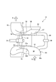
- FIG. 2 is a schematic diagram illustrating a VTI supercharger with a variable capacity turbine.
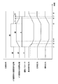
- FIG. 3 is a time chart showing supercharger switching control when the main engine load is constant by the control device for the internal combustion engine.
- FIG. 4 is a time chart showing supercharger switching control when the main engine load changes by the control device for the internal combustion engine.
- FIG. 1 is a schematic configuration diagram showing a marine diesel engine as an internal combustion engine of the present embodiment.
- a marine diesel engine 10 as an internal combustion engine includes a diesel engine main body (internal combustion engine main body) 11, a VTI supercharger 12, and a control device 13.
- the diesel engine main body 11 is provided with a plurality of cylinder parts 21, and each cylinder part 21 has a piston 22 supported therein in a freely reciprocating manner, and each piston 22 has a lower part of a piston rod 23. It is connected to the crankshaft via a cross head (not shown).
- the cylinder portion 21 is connected to a scavenging trunk 25 via a scavenging port 24 provided at the lower part, and is connected to an exhaust manifold 27 via an exhaust port 26 provided at the upper part.
- the scavenging trunk 25 is connected to a compressor (compressor) 31 of the VTI supercharger 12 via an intake pipe L1.
- the exhaust manifold 27 is connected to the turbine 32 of the VTI supercharger 12 via the exhaust pipe L2.
- the cylinder portion 21 is provided with an exhaust valve 28 for discharging exhaust gas to the exhaust port 26 at the top.
- the cylinder part 21 is provided with an injector (fuel injection valve) 29 for injecting fuel (for example, heavy oil, natural gas) into the inside (combustion chamber).
- the scavenging port 24 opens, so that the combustion gas in the scavenging trunk 25 is introduced from the scavenging port 24 into the combustion chamber, and the piston 22 rises.
- the conduction between the scavenging port 24 and the combustion chamber is blocked by the piston 22.
- the exhaust port 26 by the exhaust valve 28, the combustion gas in the combustion chamber is compressed.
- the piston 22 moves to the top dead center (the two-dot chain line position in FIG. 2), the pressure in the combustion chamber becomes a predetermined compression pressure, and the injector 29 injects fuel.
- the exhaust valve 28 can be opened and closed by an exhaust valve operating device 41.
- the exhaust valve 28 is urged and supported in a direction to close the exhaust port by an urging member (not shown) (for example, a compression spring, an air spring, etc.).
- the hydraulic oil supply pipe 42 is connected to a hydraulic oil tank (not shown) at one end, is connected to the exhaust valve 28 at the other end, and is provided with an oil supply pump 43 in the middle.
- the opening / closing valve 44 is opened from the state where the exhaust valve 28 closes the exhaust port 26 by the biasing member, the oil pump 43 is driven, and the hydraulic oil pressurized by the oil pump 43 passes through the hydraulic oil supply pipe 42. It is supplied to the exhaust valve operating device 41 and lowers the exhaust valve 28 against the urging member. Then, the exhaust valve 28 opens the exhaust port 16 only while the on-off valve 44 is open.
- the injector 29 can inject fuel into the combustion chamber of the cylinder portion 21.
- the fuel supply pipe 46 is connected to a fuel tank (not shown) at one end, is connected to the injector 29 at the other end, is provided with a fuel pump 47 in the middle, and opens the on-off valve 48.
- the fuel pump 47 is driven, and the fuel pressurized by the fuel pump 47 is supplied to the injector 29 through the fuel supply pipe 46. Then, the injector 29 injects fuel into the combustion chamber of the cylinder portion 21 only while the on-off valve 48 is open.
- the VTI supercharger 12 is a VTI (Variable Turbine Inlet) supercharger equipped with a variable capacity turbine capable of changing the turbine capacity in two stages.
- the VTI supercharger 12 includes a compressor 31 and a turbine (axial turbine) 32 that are coaxially connected via a rotating shaft 33, and the compressor 31 and the turbine 32 rotate integrally with the rotating shaft 33.
- the compressor 31 is an outside air intake type, and an intake pipe L1 reaching the scavenging trunk 25 is connected to the compressor 31.
- the turbine 32 is connected to an exhaust pipe L2 leading to the exhaust manifold 27 and an exhaust pipe L4 that exhausts to the outside.
- FIG. 2 is a schematic diagram illustrating a VTI supercharger with a variable capacity turbine.
- the gas inlet casing 50 is configured by integrally fastening an inner casing 51 and an outer casing 52, and is formed between the inner casing 51 and the outer casing 52.
- a main exhaust gas flow channel 54 for guiding the exhaust gas G to the turbine nozzle 53 is provided in the space.
- the main exhaust gas channel 54 is formed over the entire circumference of the gas inlet casing 50 in the rotation direction, and the exhaust gas G introduced from the gas inlet 50a of the gas inlet casing 50 passes through the main exhaust gas channel 54 and passes through the gas outlet 50b. Then, the gas is discharged from the outlet portion of the gas outlet casing 55 to the outside.
- the turbine nozzle 53 is provided at the gas outlet 50 b of the gas inlet casing 50.
- the rotating shaft 33 is rotatably supported by a bearing (not shown), and the turbine 32 is integrally fixed to one end portion in the axial direction.
- the turbine 32 is provided with a plurality of turbine rotor blades 56 along the circumferential direction on the outer peripheral portion.
- the turbine rotor blade 56 is provided close to the downstream side serving as the outlet of the turbine nozzle 53, and the high temperature exhaust gas ejected from the turbine nozzle 53 passes through the turbine rotor blade 56 and expands, whereby the turbine 32 is expanded. Rotate.
- a sub exhaust gas passage 57 that guides the exhaust gas branched in the middle of the main exhaust gas passage 54 to the inner peripheral side to the inner peripheral side of the turbine nozzle 53 is formed over the entire circumference in the rotation direction of the turbine 32.
- the auxiliary exhaust gas channel 57 is provided on the inner peripheral side of the main exhaust gas channel 54, and the main exhaust gas channel 54 and the auxiliary exhaust gas channel 57 are partitioned by a partition wall 58 that forms the inner casing 51.
- the connecting pipe 59 has one end connected to the inner casing 51 and communicated with the main exhaust gas flow channel 54, and the other end connected to the inner casing 51 and communicated with the auxiliary exhaust gas flow channel 57.
- the connecting pipe 59 is provided with an on-off valve (switching valve, for example, butterfly valve) 60 in the middle. Therefore, when the on-off valve 60 is opened, the exhaust gas G branched in the middle of the main exhaust gas channel 54 is guided to the sub exhaust gas channel 57 through the channel inside the connection pipe 59.
- the turbine nozzle 53 is provided with a partition wall 61 that partitions the inner peripheral side and the outer peripheral side of the turbine nozzle 53 so as to continue to the end of the partition wall 58 on the root side (rotation center side of the turbine 32). Yes.
- the on-off valve 60 is closed. Then, the entire amount of the exhaust gas G introduced from the gas inlet 50a of the gas inlet casing 50 is guided to the gas outlet 50b through the main exhaust gas channel 54. The exhaust gas G guided to the gas outlet 50 b is sucked into the outer peripheral side of the turbine nozzle 53 (the space on the outer peripheral side of the partition wall 61), expands when passing through the turbine rotor blade 56, and causes the turbine 32 and the rotary shaft 33 to move. Rotate.
- the on-off valve 60 is opened. Then, the exhaust gas G introduced from the gas inlet 50a of the gas inlet casing 50 is guided to the gas outlet 50b through the main exhaust gas passage 54, and further from the connecting pipe 59 through the sub exhaust gas passage 57 to the gas outlet 57a. Led to. The exhaust gas G guided to the gas outlet 50b is sucked into the outer peripheral side of the turbine nozzle 53, and the exhaust gas G guided to the gas outlet 57a is the inner peripheral side of the turbine nozzle 53 (the space on the inner peripheral side of the partition wall 61). And is expanded when passing through the turbine rotor blade 56 to rotate the turbine 32 and the rotating shaft 33.
- the turbine 32 is driven by exhaust gas (combustion gas) guided from the exhaust manifold 27 through the exhaust pipe L2, and after driving the compressor 31, the exhaust gas is discharged to the outside from the exhaust pipe L4.
- the compressor 31 is driven by the turbine 32 and compresses a gas such as air sucked from outside air, and then pumps the compressed gas such as air from the intake pipe L1 to the scavenging trunk 25 as a combustion gas.
- the control device 13 can open and close the on-off valves 44, 48 and 60. That is, the control device 13 controls the opening time, closing time, and driving time (opening time) of the exhaust valve 28 by opening and closing the opening / closing valve 44 according to the operating state of the marine diesel engine 10.
- the control device 13 controls the fuel injection start timing, the fuel injection end timing, the fuel injection amount, and the fuel injection time by the injector 29 by opening and closing the on-off valve 48 according to the operating state of the marine diesel engine 10.
- the control device 13 controls the scavenging pressure by the VTI supercharger 12 by opening and closing the on-off valve 60 according to the operating state of the marine diesel engine 10.
- the control device 13 is provided with a plurality of operation parameters for determining the operation amount of the operation member in accordance with the turbine capacity of the turbine (variable capacity turbine) 32.
- the operation members are the exhaust valve 28 and the injector 29 described above, and there are various hydraulic operation devices other than the exhaust valve 28 and the injector 29. That is, the VTI supercharger 12 has a low load operation mode in which the on / off valve 60 is closed when the diesel engine body 11 is under a low load, and a high load operation mode in which the on / off valve 60 is opened when the diesel engine body 11 is at a high load. Is set. Therefore, the control device 13 switches between the low load operation mode and the high load operation mode according to the operation state of the diesel engine body 11.
- the optimum opening timing, closing timing, and driving time of the exhaust valve 28 are set according to the operating state of the marine diesel engine 10, and the fuel injection start timing, fuel injection end timing, fuel injection amount, fuel injection by the injector 29 are set.
- the injection time is set. Therefore, the optimal opening timing, closing timing, driving time of the exhaust valve 28 according to the low load operation mode of the VTI supercharger 12, the fuel injection start timing by the injector 29, the fuel injection end timing, the fuel injection amount, the fuel injection time.
- the operation parameter B for which the time is set is set.
- the control device 13 switches between the operation parameter A and the operation parameter B, thereby opening the optimum exhaust valve 28.
- Timing, closing timing, drive time, fuel injection start timing by the injector 29, fuel injection end timing, fuel injection amount, and fuel injection time are set.
- the control device 13 switches the operation parameter A from the operation parameter A to the operation parameter B.
- the control device 13 passes a predetermined delay time set in advance from the mode switching. Later, the operation parameter B is switched to the operation parameter A.
- the delay time is It is desirable to set by adding a preset margin time to the switching time of the on-off valve 60.
- the switching time and allowance time of the on-off valve 60 are preferably set based on design data of the on-off valve 60 and experimental data to be implemented in advance.
- the diesel engine main body 11 is provided with a pressure sensor (in-cylinder pressure measurement estimation device) that measures the pressure of the combustion chamber in the cylinder portion 21 (hereinafter, in-cylinder pressure), and when the mode of the VTI supercharger 12 is switched. After the in-cylinder pressure has decreased or increased, the time until a predetermined value (for example, the rate of change in the in-cylinder pressure reaches a predetermined value or less) may be set as the delay time.
- a pressure sensor in-cylinder pressure measurement estimation device
- the in-cylinder pressure and the scavenging pressure may be estimated from various detection data.
- FIG. 3 is a time chart showing the supercharger switching control when the main engine load is constant by the control device of the internal combustion engine
- FIG. 4 is a time chart showing the supercharger switching control when the main engine load is changed by the control device of the internal combustion engine. is there.
- the VTI supercharger 12 is set in the low load operation mode until time t1, and the on-off valve 60 is closed so that the total amount of the exhaust gas G is reduced to the main exhaust gas flow.
- the air is sucked into the outer peripheral side of the turbine nozzle 53 through the passage 54 to rotate the turbine 32 and the compressor 31. Therefore, compared with the case where the load of the diesel engine main body 11 is the same and the on-off valve 60 is not closed, the rotation of the compressor 31 increases, the scavenging pressure increases, and the in-cylinder pressure also increases.
- the control device 13 When the main engine load, the scavenging pressure, and the like are constant, when the opening / closing command signal for opening the opening / closing valve 60 is output to the opening / closing valve 60 at time t1, the control device 13 outputs the opening / closing valve 60. Is operated to the open side, whereby the VTI supercharger 12 is switched to the high load operation mode. At this time, since the on-off valve 60 is gradually opened, the exhaust gas G also flows to the side of the sub exhaust gas flow channel 57 and the gas passage area of the turbine nozzle 53 increases, so the rotational speed of the turbine 32 and the compressor 31 decreases. In addition, the scavenging pressure decreases and the in-cylinder pressure also decreases.
- the control device 13 outputs an opening / closing command signal for opening the opening / closing valve 60
- the operation parameter A is switched to the operation parameter B. Therefore, the maximum in-cylinder pressure rapidly decreases until time t2 in accordance with changes in the opening timing of the exhaust valve 28, the fuel injection timing by the injector 29, and the time, but thereafter gradually decreases.
- the on-off valve 60 moves to the open position at time t3
- the scavenging pressure is stabilized and the in-cylinder pressure is stabilized after time t4.
- the control device 13 when the control device 13 outputs an opening / closing command signal for closing the opening / closing valve 60, the control device 13 does not switch from the operation parameter B to the operation parameter A, but from the operation parameter B at time t7 after the elapse of the delay time t + ⁇ t. Switch to operation parameter A. For this reason, since the opening timing of the exhaust valve 28, the fuel injection timing by the injector 29, and the time are not changed from time t5 to time t6, the maximum in-cylinder pressure increases gently without increasing rapidly.
- the delay time t + ⁇ t is set by adding a margin time ⁇ t to the switching time t of the on-off valve 60.
- the operation parameter B is switched to the operation parameter A.
- the opening timing of the exhaust valve 28, the fuel injection timing by the injector 29, the time Therefore, there is a possibility that the maximum in-cylinder pressure suddenly increases and overshoots from time t5 to time t6.
- the operation parameter corresponding to the operation mode of the VTI supercharger 12 is not set, the maximum in-cylinder pressure in the low load operation mode of the VTI supercharger 12 as shown by a two-dot chain line in FIG. Will be lower.
- the operation parameter B by switching from the operation parameter B to the operation parameter A in the low load operation mode of the VTI supercharger 12, as shown by the solid line in FIG. High in-cylinder pressure can be maintained.
- the control device 13 When the load on the diesel engine body 11 increases and the turbine capacity decreases, as shown in FIGS. 1 and 4, when the main engine load increases, at time t ⁇ b> 11, the control device 13 outputs an opening / closing command signal for opening the opening / closing valve 60 to the opening / closing valve 60. Then, when the on-off valve 60 is operated to the open side, the VTI supercharger 12 is switched to the high load operation mode. At this time, since the on-off valve 60 is gradually opened, the exhaust gas G also flows to the side of the sub exhaust gas flow channel 57 and the gas passage area of the turbine nozzle 53 increases, so the rotational speed of the turbine 32 and the compressor 31 decreases. In addition, the scavenging pressure decreases and the in-cylinder pressure also decreases.
- the operation parameter A is switched to the operation parameter B. Therefore, the maximum in-cylinder pressure rapidly decreases until time t12 in accordance with the change of the opening timing of the exhaust valve 28, the fuel injection timing by the injector 29, and the time, but then gradually decreases.
- the on-off valve 60 moves to the open position at time t13, the scavenging pressure increases as the main engine load increases, and the in-cylinder pressure also increases. After time t14, the main engine load is constant, the scavenging pressure is stabilized, and the in-cylinder pressure is also stabilized.
- the control device 13 opens and closes the opening / closing valve 60 with respect to the opening / closing valve 60 at time t16.
- the on / off valve 60 operates to the closed side, so that the VTI supercharger 12 is switched to the low load operation mode.
- the nozzle passage area of the exhaust gas G flowing to the sub exhaust gas flow channel 57 side decreases, the rotational speed of the turbine 32 and the compressor 31 increases, and the scavenging pressure is reduced.
- the in-cylinder pressure also rises.
- the control device 13 when the control device 13 outputs an opening / closing command signal for closing the opening / closing valve 60, the control device 13 does not switch from the operation parameter B to the operation parameter A, but from the operation parameter B at time t8 after the elapse of the delay time t + ⁇ t. Switch to operation parameter A. Therefore, since the opening timing of the exhaust valve 28, the fuel injection timing by the injector 29, and the time are not changed from time t16 to time t18, the maximum in-cylinder pressure increases gently without increasing rapidly.
- the control device 13 switches from the operation parameter B to the operation parameter A.
- the control device 13 outputs the opening / closing command signal for closing the opening / closing valve 60, the operation parameter B is switched to the operation parameter A.
- the opening timing of the exhaust valve 28, the fuel injection timing by the injector 29, the time From time t16 to time t17, the maximum in-cylinder pressure may suddenly increase and overshoot from time t16 to time t17, as indicated by a two-dot chain line in FIG.
- the maximum in-cylinder pressure becomes lower than the optimum value in the load in the low load operation mode of the VTI supercharger 12.
- the operation parameter B by switching from the operation parameter B to the operation parameter A in the low load operation mode of the VTI supercharger 12, as shown by the solid line in FIG.
- the in-cylinder pressure can be maintained at an optimum value.
- An exhaust valve 28 and an injector 29 are provided as operating members that affect the pressure
- the control device 13 has a plurality of operating parameters A and B that determine the operating amounts of the exhaust valve 28 and the injector 29 according to the capacity of the turbine 32.
- the operating parameters A and B are switched after elapse of a predetermined delay time t + ⁇ t that is provided and changes in advance when the capacity of the turbine 32 is changed.
- the operation parameters A and B are switched after a delay time t + ⁇ t has elapsed since the output of the opening / closing command signal of the opening / closing valve 60 of the VTI supercharger 12. Therefore, the operation parameters A and B can be switched at an appropriate time regardless of the time required to change the turbine capacity.
- the operation parameters A and B are switched simultaneously with the change of the capacity of the turbine 32, while when the capacity of the turbine 32 is decreased, the capacity of the turbine 32 is changed.
- the operating parameters A and B are switched after a lapse of delay time t + ⁇ t from the time of the change. Accordingly, when the capacity of the turbine 32 is reduced, the scavenging pressure increases. At this time, the rapid increase of the in-cylinder pressure is suppressed by switching the operation parameters A and B after the lapse of the delay time t + ⁇ t, and the marine diesel The reliability of the engine 10 can be improved.
- the operating parameters A and A are set after the opening / closing valve 60 has completely moved to the switching position by adding the margin time ⁇ t to the switching time t of the opening / closing valve 60 and setting the delay time. B is switched, and a rapid increase in the in-cylinder pressure can be suppressed by simple control.
- a scavenging pressure or in-cylinder pressure measurement and estimation device for measuring or estimating the scavenging pressure or in-cylinder pressure is provided, and the delay time is increased until the scavenging pressure or in-cylinder pressure reaches a constant value. It's time for. Therefore, the operating parameters A and B are switched after waiting for the in-cylinder pressure to stabilize, and a rapid increase in the in-cylinder pressure can be suppressed.
- the diesel engine main body 11, the VTI supercharger 12 including the compressor 31 and the turbine 32 that supply combustion gas to the diesel engine main body 11, and the in-cylinder pressure are affected.
- Exhaust valves 28 and injectors 29 as operating members to be provided, and a plurality of operation parameters A and B for determining the operation amounts of the exhaust valves 28 and injectors 29 according to the capacity of the turbine 32 are provided, and when the capacity of the turbine 32 is changed in advance, There is provided a control device 13 for switching the operation parameters A and B after a predetermined delay time t + ⁇ t has elapsed. Therefore, the behavior of the in-cylinder pressure due to the change of the scavenging pressure and the switching of the operation parameters A and B is reduced, and the performance of the marine diesel engine 10 can be stabilized.
Landscapes
- Engineering & Computer Science (AREA)
- Chemical & Material Sciences (AREA)
- Combustion & Propulsion (AREA)
- Mechanical Engineering (AREA)
- General Engineering & Computer Science (AREA)
- Supercharger (AREA)
- Output Control And Ontrol Of Special Type Engine (AREA)
- Combined Controls Of Internal Combustion Engines (AREA)
Abstract
内燃機関の制御装置及び内燃機関において、ディーゼルエンジン本体(11)と、ディーゼルエンジン本体(11)に燃焼用気体を供給するコンプレッサ(31)及びタービン(32)を備えるVTI過給機(12)と、筒内圧力に影響を与える作動部材としての排気弁(28)及びインジェクタ(29)を設け、制御装置(13)は、タービン(32)の容量に応じた排気弁(28)及びインジェクタ(29)の作動量を決定する複数の運転パラメータ(A,B)が設けられ、タービン(32)の容量の変更時に予め設定された所定の遅れ時間(t+Δt)の経過後に運転パラメータ(A,B)を切り替える。
Description
本発明は、過給機を備える内燃機関の制御装置、この内燃機関の制御装置を備える内燃機関に関するものである。
例えば、船舶に搭載される主機としての内燃機関は、燃費向上や排ガス中のCO2を削減するために過給機が装着されている。この過給機は、内燃機関から排出される排ガスを利用してタービン及びコンプレッサを駆動することにより、内燃機関に燃焼用気体を圧縮供給して内燃機関の出力を向上させるものである。
このような過給機として、可変容量タービンを備えた可変タービンシステムがある。この可変タービンシステムは、可変タービンノズルを排ガスの入口部に配置すると共に、排ガスのガス入口通路を2系統に分割して一方のガス入口通路に開閉弁を設けたものである。そのため、開閉弁の開閉動作によりノズルスロート面積を変化させることを可能とし、内燃機関の低負荷運転域において、ノズルスロート面積を減少して掃気圧力を上昇し、燃料消費率を低減することができる。なお、このような技術として、例えば、下記特許文献に記載されているものがある。
上述した可変タービンシステムでは、一方のガス入口通路に設けられた開閉弁の開閉動作によりノズルスロート面積を変化させ、内燃機関の運転状態に応じて掃気圧力を調整するように制御している。一方で、内燃機関に運転状態に応じて調整するものとして、例えば、燃料噴射時間や燃料噴射時期、排気弁駆動時間や排気弁開閉時期などがあり、これらは予め設定された運転パラメータにより制御されている。そのため、可変タービン容量システムによる掃気圧力が変化したとき、内燃機関の性能がばらついてしまうという問題がある。
本発明は、上述した課題を解決するものであり、掃気圧力の変化に応じた筒内圧力の挙動を低減して内燃機関の性能の安定化を図る内燃機関の制御装置及び内燃機関を提供することを目的とする。
上記の目的を達成するための本発明の内燃機関の制御装置は、内燃機関本体と、前記内燃機関本体に接続されて前記内燃機関本体に燃焼用気体を供給する圧縮機及び前記圧縮機と同軸回転する可変容量タービンを備える過給機と、前記内燃機関本体に設けられて筒内圧力に影響を与える作動部材と、を備え、前記タービンの容量に応じた前記作動部材の作動量を決定する複数の運転パラメータが設けられ、前記タービンの容量の変更時に予め設定された所定の遅れ時間の経過後に前記運転パラメータを切り替える、ことを特徴とするものである。
従って、タービン容量の変更時に、所定の遅れ時間の経過後に作動部材の運転パラメータを切り替えることで、掃気圧力の変化と運転パラメータの切替による筒内圧力の挙動が低減され、内燃機関の性能の安定化を図ることができる。
本発明の内燃機関の制御装置では、前記タービンの容量の変更指令の出力時から前記遅れ時間の経過後に前記運転パラメータを切り替えることを特徴としている。
従って、タービン容量の変更指令の出力時から遅れ時間の経過後に運転パラメータを切り替えることで、タービン容量を変更するのに要する時間に拘わらず、適正時期に運転パラメータを切り替えることができる。
本発明の内燃機関の制御装置では、前記タービンの容量の増加時は、前記タービンの容量の変更と同時に前記運転パラメータを切り替える一方、前記タービンの容量の減少時は、前記タービンの容量の変更時から前記遅れ時間の経過後に前記運転パラメータを切り替えることを特徴としている。
従って、タービン容量が増加するときは、掃気圧力が低下するが、タービン容量の減少時は、掃気圧力が上昇するため、タービン容量の変更時から遅れ時間の経過後に運転パラメータを切り替える。そのため、筒内圧力の急激な上昇が抑制され、内燃機関の信頼性を向上することができる。
本発明の内燃機関の制御装置では、前記過給機は、前記タービンの容量を変更切替可能な切替弁が設けられ、前記遅れ時間は、前記切替弁の切替時間に予め設定された余裕時間を加算して設定されることを特徴としている。
従って、切替弁の切替時間に余裕時間を加算して遅れ時間を設定することで、切替弁が切替位置に完全に移動した後に運転パラメータが切り替わることとなり、簡単な制御により筒内圧力の急激な上昇を抑制することができる。
本発明の内燃機関の制御装置では、掃気圧力または筒内圧力を計測または推定する掃気圧力または筒内圧力計測推定装置が設けられ、前記遅れ時間は、前記掃気圧力または前記筒内圧力が一定値に到達するまでの時間であることを特徴としている。
従って、計測または推定された掃気圧力または筒内圧力が一定値に到達するまでの時間を遅れ時間とすることで、筒内圧力の安定を待って運転パラメータが切り替わることとなり、筒内圧力の急激な上昇を抑制することができる。
本発明の内燃機関の制御装置では、前記作動部材は、排気弁と燃料噴射弁と油圧作動機器の少なくともいずれか一つであることを特徴としている。
従って、タービン容量に応じて、排気弁の開閉時期、燃料噴射弁の燃料噴射時期、燃料噴射時間、油圧作動機器の作動圧力等の運転パラメータを適正時期に設定することができる。
また、本発明の内燃機関は、内燃機関本体と、前記内燃機関本体に接続されて前記内燃機関本体に燃焼用気体を供給する圧縮機及び前記圧縮機と同軸回転する可変容量タービンを備える過給機と、前記内燃機関本体に設けられて筒内圧力に影響を与える作動部材と、前記タービンの容量に応じた前記作動部材の作動量を決定する複数の運転パラメータが設けられて前記タービンの容量の変更時に予め設定された所定の遅れ時間の経過後に前記運転パラメータを切り替える制御装置と、を備えることを特徴とするものである。
従って、タービン容量の変更時に、所定の遅れ時間の経過後に作動部材の運転パラメータを切り替えることで、掃気圧力の変化と運転パラメータの切替による筒内圧力の挙動が低減され、内燃機関の性能の安定化を図ることができる。
本発明の内燃機関の制御装置及び内燃機関によれば、掃気圧力の変化と運転パラメータの切替による筒内圧力の挙動が低減され、内燃機関の性能の安定化を図ることができる。
以下に添付図面を参照して、本発明に係る内燃機関の制御装置及び内燃機関の好適な実施形態を詳細に説明する。なお、この実施形態により本発明が限定されるものではなく、また、実施形態が複数ある場合には、各実施形態を組み合わせて構成するものも含むものである。
図1は、本実施形態の内燃機関としての舶用ディーゼルエンジンを表す概略構成図である。
本実施形態にて、図1に示すように、内燃機関としての舶用ディーゼルエンジン10は、ディーゼルエンジン本体(内燃機関本体)11と、VTI過給機12と、制御装置13とを備えている。
ディーゼルエンジン本体11は、複数のシリンダ部21が設けられており、それぞれのシリンダ部21は、内部にピストン22がそれぞれ往復移動自在に支持されており、各ピストン22は、ピストン棒23の下部が図示しないクロスヘッドを介してクランク軸に連結されている。
シリンダ部21は、下部に設けられた掃気ポート24を介して掃気トランク25が連結されると共に、上部設けられた排気ポート26を介して排気マニホールド27が連結されている。掃気トランク25は、吸気管L1を介してVTI過給機12のコンプレッサ(圧縮機)31に連結されている。排気マニホールド27は、排気管L2を介してVTI過給機12のタービン32に連結されている。また、シリンダ部21は、上部に排ガスを排気ポート26に排出する排気弁28が設けられている。更に、シリンダ部21は、内部(燃焼室)に燃料(例えば、重油、天然ガスなど)を噴射するインジェクタ(燃料噴射弁)29が設けられている。
そのため、ピストン22の下死点(図1の実線位置)に移動すると、掃気ポート24が開くことで、掃気トランク25の燃焼用気体が掃気ポート24から燃焼室に導入され、ピストン22が上昇すると、掃気ポート24と燃焼室の導通がピストン22により遮断される。さらに、排気弁28により排気ポート26も閉じることによって、燃焼室内の燃焼用気体が圧縮される。ピストン22が上死点(図2の二点鎖線位置)まで移動すると、燃焼室の圧力が所定の圧縮圧力になり、インジェクタ29が燃料を噴射する。すると、燃焼室内で燃焼用気体と燃料が混合して燃焼し、燃焼エネルギによりピストン22が下降する。このとき、排気弁28により排気ポート26が開くことで、燃焼室の排ガス(燃焼ガス)が排気ポート26に排出される。
排気弁28は、排気弁作動装置41により開閉可能となっている。排気弁28は、図示しない付勢部材(例えば、圧縮ばね、空気ばねなど)により排気ポートを閉止する方向に付勢支持されている。また、作動油供給配管42は、一端部に作動油タンク(図示せず)が接続されると共に、他端部が排気弁28に接続されており、中途部に給油ポンプ43が設けられており、排気弁28が付勢部材により排気ポート26を閉止する状態から、開閉弁44を開放すると、給油ポンプ43が駆動し、この給油ポンプ43で加圧された作動油が作動油供給配管42を通して排気弁作動装置41に供給され、排気弁28を付勢部材に抗して下降させる。すると、排気弁28は、開閉弁44が開放されている間だけ、排気ポート16を開放する。
インジェクタ29は、燃料をシリンダ部21の燃焼室に噴射可能となっている。燃料供給配管46は、一端部に燃料タンク(図示せず)が接続され、他端部がインジェクタ29に接続されており、中途部に燃料ポンプ47が設けられており、開閉弁48を開放すると、燃料ポンプ47が駆動し、燃料ポンプ47で加圧された燃料が燃料供給配管46を通してインジェクタ29に供給される。すると、インジェクタ29は、開閉弁48が開放されている間だけ、燃料をシリンダ部21の燃焼室に噴射する。
VTI過給機12は、タービン容量を2段階で変更可能な可変容量タービンを備えたVTI(Variable Turbine Inlet)過給機である。VTI過給機12は、コンプレッサ31とタービン(軸流タービン)32が回転軸33を介して同軸上に連結されて構成されており、コンプレッサ31とタービン32は、回転軸33により一体回転することができる。コンプレッサ31は、外気吸入式であって、掃気トランク25に至る吸気管L1が連結されている。タービン32は、排気マニホールド27に至る排気管L2が連結されると共に、外部に排気する排気管L4が連結されている。
ここで、VTI過給機12について詳細に説明する。図2は、可変容量タービンを備えたVTI過給機を表す概略図である。
VTI過給機12において、図2に示すように、ガス入口ケーシング50は、内側ケーシング51と外側ケーシング52が一体に締結されて構成され、内側ケーシング51と外側ケーシング52との間に形成される空間に排ガスGをタービンノズル53に導くための主排ガス流路54が設けられている。主排ガス流路54は、ガス入口ケーシング50の回転方向の全周にわたって形成されており、ガス入口ケーシング50のガス入口50aから導入された排ガスGは、主排ガス流路54を通ってガス出口50bに導かれた後、ガス出口ケーシング55の出口部から外部へ排出される。
タービンノズル53は、ガス入口ケーシング50のガス出口50bに設けられている。回転軸33は、軸受(図示せず)に回転自在に支持されており、軸方向の一端部にタービン32が一体に固定されている。タービン32は、外周部に周方向に沿って複数のタービン動翼56が設けられている。このタービン動翼56は、タービンノズル53の出口となる下流側に近接して設けられており、タービンノズル53から噴出する高温の排ガスがタービン動翼56を通過して膨張することによりタービン32が回転する。
内側ケーシング51は、内周側に主排ガス流路54の途中で分岐された排ガスをタービンノズル53の内周側に導く副排ガス流路57がタービン32の回転方向の全周にわたって形成されている。この副排ガス流路57は、主排ガス流路54の内周側に設けられており、主排ガス流路54と副排ガス流路57とは、内側ケーシング51を形成する仕切壁58により仕切られている。
また、連結配管59は、一端部が内側ケーシング51に接続されて主排ガス流路54に連通される一方、他端部が内側ケーシング51に接続されて副排ガス流路57に連通されている。そして、連結配管59は、中途部に開閉弁(切替弁、例えば、バタフライ弁)60が設けられている。そのため、開閉弁60の開放時、主排ガス流路54の途中で分岐された排ガスGは連結配管59内部の流路を通って副排ガス流路57に導かれる。また、タービンノズル53は、根元側(タービン32の回転中心側)に仕切壁58の端部に連続するように、タービンノズル53の内周側と外周側とを仕切る仕切壁61が設けられている。
ここで、舶用ディーゼルエンジン10の負荷が低くて排ガスGの量が少ない場合、開閉弁60を閉止する。すると、ガス入口ケーシング50のガス入口50aから導入された排ガスGの全量が主排ガス流路54を通ってガス出口50bに導かれる。ガス出口50bに導かれた排ガスGは、タービンノズル53の外周側(仕切壁61の外周側の空間)に吸い込まれ、タービン動翼56を通過するときに膨張してタービン32および回転軸33を回転させる。
一方、舶用ディーゼルエンジン10の負荷が高くて排ガスGの量が多い場合、開閉弁60を開放する。すると、ガス入口ケーシング50のガス入口50aから導入された排ガスGは、主排ガス流路54を通ってガス出口50bに導かれるとともに、さらに連結配管59から副排ガス流路57を通ってガス出口57aに導かれる。ガス出口50bに導かれた排ガスGは、タービンノズル53の外周側に吸い込まれ、ガス出口57aに導かれた排ガスGは、タービンノズル53の内周側(仕切壁61の内周側の空間)に吸い込まれ、タービン動翼56を通過するときに膨張してタービン32および回転軸33を回転させる。
そのため、図1に示すように、タービン32は、排気マニホールド27から排気管L2を通して導かれた排ガス(燃焼ガス)によって駆動し、コンプレッサ31を駆動した後、排ガスを排気管L4から外部に排出する。一方、コンプレッサ31は、タービン32により駆動し、外気から吸気した空気等の気体を圧縮した後、圧縮した空気等の気体を燃焼用気体として吸気管L1から掃気トランク25に圧送する。
図1に示すように、制御装置13は、開閉弁44,48,60を開閉制御可能となっている。即ち、制御装置13は、舶用ディーゼルエンジン10の運転状態に応じて開閉弁44を開閉操作することで、排気弁28の開放時期、閉止時期、駆動時間(開放時間)を制御する。また、制御装置13は、舶用ディーゼルエンジン10の運転状態に応じて開閉弁48を開閉操作することで、インジェクタ29による燃料噴射開始時期、燃料噴射終了時期、燃料噴射量、燃料噴射時間を制御する。更に、制御装置13は、舶用ディーゼルエンジン10の運転状態に応じて開閉弁60を開閉操作することで、VTI過給機12による掃気圧力を制御する。
ここで、制御装置13は、タービン(可変容量タービン)32のタービン容量に応じた作動部材の作動量を決定する複数の運転パラメータが設けられている。ここで、作動部材とは、上述した排気弁28とインジェクタ29であって、この排気弁28とインジェクタ29以外に、各種の油圧作動機器がある。即ち、VTI過給機12は、ディーゼルエンジン本体11の低負荷時に、開閉弁60を閉止する低負荷運転モードと、ディーゼルエンジン本体11の高負荷時に、開閉弁60を開放する高負荷運転モードとが設定されている。そのため、制御装置13は、ディーゼルエンジン本体11の運転状態に応じて低負荷運転モードと高負荷運転モードを切り替える。
一方、舶用ディーゼルエンジン10の運転状態に応じて最適な排気弁28の開放時期、閉止時期、駆動時間が設定されると共に、インジェクタ29による燃料噴射開始時期、燃料噴射終了時期、燃料噴射量、燃料噴射時間が設定される。そのため、VTI過給機12の低負荷運転モードに応じた最適な排気弁28の開放時期、閉止時期、駆動時間とインジェクタ29による燃料噴射開始時期、燃料噴射終了時期、燃料噴射量、燃料噴射時間が設定される運転パラメータAと、高負荷運転モードに応じた最適な排気弁28の開放時期、閉止時期、駆動時間とインジェクタ29による燃料噴射開始時期、燃料噴射終了時期、燃料噴射量、燃料噴射時間が設定される運転パラメータBが設定されている。
制御装置13は、VTI過給機12の運転モードが低負荷運転モードと高負荷運転モードとの間で切り替わるとき、運転パラメータAと運転パラメータBとを切り替えることで、最適な排気弁28の開放時期、閉止時期、駆動時間とインジェクタ29による燃料噴射開始時期、燃料噴射終了時期、燃料噴射量、燃料噴射時間を設定している。
また、制御装置13は、VTI過給機12が低負荷運転モードから高負荷運転モードに切り替わることで、タービン32の容量が減少するときは、モード切替と同時に運転パラメータAから運転パラメータBに切り替える。一方、制御装置13は、VTI過給機12が高負荷運転モードから低負荷運転モードに切り替わることで、タービン32の容量が増加するときは、モード切替から予め設定された所定の遅れ時間の経過後に運転パラメータBから運転パラメータAに切り替える。
この場合、制御装置13が開閉弁60に開閉指令信号を出力してから、実際に、開閉弁60が開放位置または閉止位置に移動するまでの切替時間が発生することから、遅れ時間は、この開閉弁60の切替時間に予め設定された余裕時間を加算して設定することが望ましい。そして、この開閉弁60の切替時間と余裕時間は、開閉弁60の設計データや事前の実施される実験データにより設定することが望ましい。
なお、この遅れ時間は、この設定方法に限定されるものではない。例えば、ディーゼルエンジン本体11にて、シリンダ部21内における燃焼室の圧力(以下、筒内圧力)を計測する圧力センサ(筒内圧力計測推定装置)を設け、VTI過給機12のモード切替時に、筒内圧力が減少または増加した後、予め設定された一定値(例えば、筒内圧力の変化率が所定値以下)に到達するまでの時間を遅れ時間として設定してもよい。この場合、筒内圧力を計測する圧力センサに代えて、掃気圧力を計測する圧力センサ(筒内圧力計測推定装置)でもよい。更に、各種の検出データから筒内圧力や掃気圧力を推定してもよい。
以下、VTI過給機12の運転モードの切り替えに伴う運転パラメータの切替制御について詳細に説明する。図3は、内燃機関の制御装置による主機負荷一定時の過給機切替制御を表すタイムチャート、図4は、内燃機関の制御装置による主機負荷変化時の過給機切替制御を表すタイムチャートである。
(ディーゼルエンジン本体11の負荷が一定でタービン容量が増加する場合)
図1及び図3に示すように、VTI過給機12は、時間t1までの間、低負荷運転モードに設定されており、開閉弁60が閉止することで、排ガスGの全量が主排ガス流路54を通ってタービンノズル53の外周側に吸い込まれ、タービン32及びコンプレッサ31を回転させる。そのため、ディーゼルエンジン本体11の負荷が同じで、かつ開閉弁60を閉止しない場合と比較して、コンプレッサ31の回転が上昇し、掃気圧力が上昇するとともに、筒内圧力も上昇する。
図1及び図3に示すように、VTI過給機12は、時間t1までの間、低負荷運転モードに設定されており、開閉弁60が閉止することで、排ガスGの全量が主排ガス流路54を通ってタービンノズル53の外周側に吸い込まれ、タービン32及びコンプレッサ31を回転させる。そのため、ディーゼルエンジン本体11の負荷が同じで、かつ開閉弁60を閉止しない場合と比較して、コンプレッサ31の回転が上昇し、掃気圧力が上昇するとともに、筒内圧力も上昇する。
主機負荷及び掃気圧力などが一定である場合、時間t1にて、制御装置13は、開閉弁60に対して、この開閉弁60を開放するための開閉指令信号が出力されると、開閉弁60が開放側に作動することで、VTI過給機12が高負荷運転モードに切り替わる。このとき、開閉弁60が徐々に開放されることで、排ガスGが副排ガス流路57側にも流れてタービンノズル53のガス通過面積が増加するため、タービン32及びコンプレッサ31の回転数が低下し、掃気圧力が低下すると共に、筒内圧力も低下する。
また、制御装置13が開閉弁60を開放するための開閉指令信号を出力すると同時に、運転パラメータAから運転パラメータBに切り替わる。そのため、排気弁28の開放時期やインジェクタ29による燃料噴射時期、時間の変更に応じて、最高筒内圧力が時間t2まで急激に減少するが、その後、なだらかに減少する。時間t3にて、開閉弁60が開放位置まで移動すると、時間t4以降は、掃気圧力が安定し、筒内圧力も安定する。
(ディーゼルエンジン本体11の負荷が一定でタービン容量が減少する場合)
一方、時間t5にて、制御装置13は、開閉弁60に対して、この開閉弁60を閉止するための開閉指令信号が出力されると、開閉弁60が閉止側に作動することで、VTI過給機12が低負荷運転モードに切り替わる。このとき、開閉弁60が徐々に閉止されることで、副排ガス流路57側に流れる排ガスGのノズル通過面積が減少していき、タービン32及びコンプレッサ31の回転数が上昇し、掃気圧力が上昇すると共に、筒内圧力も上昇する。
一方、時間t5にて、制御装置13は、開閉弁60に対して、この開閉弁60を閉止するための開閉指令信号が出力されると、開閉弁60が閉止側に作動することで、VTI過給機12が低負荷運転モードに切り替わる。このとき、開閉弁60が徐々に閉止されることで、副排ガス流路57側に流れる排ガスGのノズル通過面積が減少していき、タービン32及びコンプレッサ31の回転数が上昇し、掃気圧力が上昇すると共に、筒内圧力も上昇する。
一方、制御装置13は、開閉弁60を閉止するための開閉指令信号を出力したとき、運転パラメータBから運転パラメータAに切り替えずに、遅れ時間t+Δtの経過後に時間t7にて、運転パラメータBから運転パラメータAに切り替える。そのため、時間t5から時間t6の間、排気弁28の開放時期やインジェクタ29による燃料噴射時期、時間が変更されないことから、最高筒内圧力が急激に増加せずになだらかに増加する。
その後、時間t6にて、開閉弁60が閉止位置まで移動すると、時間t7にて、遅れ時間t+Δtが経過するため、ここで、制御装置13は、運転パラメータBから運転パラメータAに切り替える。すると、時間t8以降は、掃気圧力が安定し、筒内圧力も安定する。ここで、遅れ時間t+Δtは、開閉弁60の切替時間tに余裕時間Δtを加算して設定されている。
制御装置13が開閉弁60を閉止するための開閉指令信号を出力したときに、運転パラメータBから運転パラメータAに切り替えると、ここで、排気弁28の開放時期やインジェクタ29による燃料噴射時期、時間が変更されることから、時間t5から時間t6の間で、最高筒内圧力が急激に増加してオーバーシュートしてしまう可能性がある。また、VTI過給機12の運転モードに応じた運転パラメータが設定されていないと、図3に2点鎖線で表すように、VTI過給機12の低負荷運転モードにて、最高筒内圧力が低くなってしまう。一方、VTI過給機12の低負荷運転モードにて、運転パラメータBから運転パラメータAに切り替わることで、図3に実線で表すように、VTI過給機12の低負荷運転モードにて、最高筒内圧力を高く維持できる。
(ディーゼルエンジン本体11の負荷が上昇してタービン容量が減少する場合)
図1及び図4に示すように、主機負荷が上昇するとき、時間t11にて、制御装置13は、開閉弁60に対して、この開閉弁60を開放するための開閉指令信号が出力されると、開閉弁60が開放側に作動することで、VTI過給機12が高負荷運転モードに切り替わる。このとき、開閉弁60が徐々に開放されることで、排ガスGが副排ガス流路57側にも流れてタービンノズル53のガス通過面積が増加するため、タービン32及びコンプレッサ31の回転数が低下し、掃気圧力が低下すると共に、筒内圧力も低下する。
図1及び図4に示すように、主機負荷が上昇するとき、時間t11にて、制御装置13は、開閉弁60に対して、この開閉弁60を開放するための開閉指令信号が出力されると、開閉弁60が開放側に作動することで、VTI過給機12が高負荷運転モードに切り替わる。このとき、開閉弁60が徐々に開放されることで、排ガスGが副排ガス流路57側にも流れてタービンノズル53のガス通過面積が増加するため、タービン32及びコンプレッサ31の回転数が低下し、掃気圧力が低下すると共に、筒内圧力も低下する。
また、制御装置13が開閉弁60を開放するための開閉指令信号を出力すると同時に、運転パラメータAから運転パラメータBに切り替わる。そのため、排気弁28の開放時期やインジェクタ29による燃料噴射時期、時間の変更に応じて、最高筒内圧力が時間t12まで急激に減少するが、その後、なだらかに減少する。時間t13にて、開閉弁60が開放位置まで移動すると、主機負荷の上昇に伴って掃気圧力が上昇し、筒内圧力も上昇する。そして、時間t14以降は、主機負荷が一定となり、掃気圧力が安定し、筒内圧力も安定する。
(ディーゼルエンジン本体11の負荷が減少してタービン容量が増加する場合)
一方、時間t15にて、主機負荷が低下して掃気圧力と筒内圧力も低下すると、時間t16にて、制御装置13は、開閉弁60に対して、この開閉弁60を閉止するための開閉指令信号が出力されると、開閉弁60が閉止側に作動することで、VTI過給機12が低負荷運転モードに切り替わる。このとき、開閉弁60が徐々に閉止されることで、副排ガス流路57側に流れる排ガスGのノズル通過面積が減少していき、タービン32及びコンプレッサ31の回転数が上昇し、掃気圧力が上昇すると共に、筒内圧力も上昇する。
一方、時間t15にて、主機負荷が低下して掃気圧力と筒内圧力も低下すると、時間t16にて、制御装置13は、開閉弁60に対して、この開閉弁60を閉止するための開閉指令信号が出力されると、開閉弁60が閉止側に作動することで、VTI過給機12が低負荷運転モードに切り替わる。このとき、開閉弁60が徐々に閉止されることで、副排ガス流路57側に流れる排ガスGのノズル通過面積が減少していき、タービン32及びコンプレッサ31の回転数が上昇し、掃気圧力が上昇すると共に、筒内圧力も上昇する。
一方、制御装置13は、開閉弁60を閉止するための開閉指令信号を出力したとき、運転パラメータBから運転パラメータAに切り替えずに、遅れ時間t+Δtの経過後に時間t8にて、運転パラメータBから運転パラメータAに切り替える。そのため、時間t16から時間t18の間、排気弁28の開放時期やインジェクタ29による燃料噴射時期、時間が変更されないことから、最高筒内圧力が急激に増加せずになだらかに増加する。
その後、時間t17にて、開閉弁60が閉止位置まで移動すると、時間t18にて、遅れ時間t+Δtが経過するため、ここで、制御装置13は、運転パラメータBから運転パラメータAに切り替える。制御装置13が開閉弁60を閉止するための開閉指令信号を出力したときに、運転パラメータBから運転パラメータAに切り替えると、ここで、排気弁28の開放時期やインジェクタ29による燃料噴射時期、時間が変更されることから、時間t16から時間t17の間で、図4に2点鎖線で表すように、最高筒内圧力が急激に増加してオーバーシュートしてしまう可能性がある。また、VTI過給機12の運転モードに応じた運転パラメータが設定されていないと、VTI過給機12の低負荷運転モードにて、最高筒内圧力が負荷における最適値より低くなってしまう。一方、VTI過給機12の低負荷運転モードにて、運転パラメータBから運転パラメータAに切り替わることで、図4に実線で表すように、VTI過給機12の低負荷運転モードにて、最高筒内圧力を最適値に維持できる。
このように本実施形態の内燃機関の制御装置にあっては、ディーゼルエンジン本体11と、ディーゼルエンジン本体11に燃焼用気体を供給するコンプレッサ31及びタービン32を備えるVTI過給機12と、筒内圧力に影響を与える作動部材としての排気弁28及びインジェクタ29を設け、制御装置13は、タービン32の容量に応じた排気弁28及びインジェクタ29の作動量を決定する複数の運転パラメータA,Bが設けられ、タービン32の容量の変更時に予め設定された所定の遅れ時間t+Δtの経過後に運転パラメータA,Bを切り替えるようにしている。
従って、VTI過給機12のタービン32の容量の変更時に、遅れ時間t+Δtの経過後に運転パラメータA,Bを切り替えることで、掃気圧力の変化と運転パラメータA,Bの切替による筒内圧力の挙動が低減され、舶用ディーゼルエンジン10の性能の安定化を図ることができる。
本実施形態の内燃機関の制御装置では、VTI過給機12の開閉弁60の開閉指令信号の出力時から遅れ時間t+Δtの経過後に、運転パラメータA,Bを切り替える。従って、タービン容量を変更するのに要する時間に拘わらず、適正時期に運転パラメータA,Bを切り替えることができる。
本実施形態の内燃機関の制御装置では、タービン32の容量の増加時は、タービン32の容量の変更と同時に運転パラメータA,Bを切り替える一方、タービン32の容量の減少時は、タービン32の容量の変更時から遅れ時間t+Δtの経過後に運転パラメータA,Bを切り替える。従って、タービン32の容量の減少時は、掃気圧力が上昇するため、このときは遅れ時間t+Δtの経過後に運転パラメータA,Bを切り替えることで、筒内圧力の急激な上昇が抑制され、舶用ディーゼルエンジン10の信頼性を向上することができる。
本実施形態の内燃機関の制御装置では、開閉弁60の切替時間tに余裕時間Δtを加算して遅れ時間を設定することで、開閉弁60が切替位置に完全に移動した後に運転パラメータA,Bが切り替わることとなり、簡単な制御により筒内圧力の急激な上昇を抑制することができる。
本実施形態の内燃機関の制御装置では、掃気圧力または筒内圧力を計測または推定する掃気圧力または筒内圧力計測推定装置を設け、遅れ時間を掃気圧力または筒内圧力が一定値に到達するまでの時間としている。従って、筒内圧力の安定を待って運転パラメータA,Bが切り替わることとなり、筒内圧力の急激な上昇を抑制することができる。
また、本実施形態の内燃機関にあっては、ディーゼルエンジン本体11と、ディーゼルエンジン本体11に燃焼用気体を供給するコンプレッサ31及びタービン32を備えるVTI過給機12と、筒内圧力に影響を与える作動部材としての排気弁28及びインジェクタ29と、タービン32の容量に応じた排気弁28及びインジェクタ29の作動量を決定する複数の運転パラメータA,Bを設けてタービン32の容量の変更時に予め設定された所定の遅れ時間t+Δtの経過後に運転パラメータA,Bを切り替える制御装置13とを設けている。従って、掃気圧力の変化と運転パラメータA,Bの切替による筒内圧力の挙動が低減され、舶用ディーゼルエンジン10の性能の安定化を図ることができる。
10 舶用ディーゼルエンジン(内燃機関)
11 ディーゼルエンジン本体(内燃機関本体)
12 VTI過給機(過給機)
13 制御装置
21 シリンダ部
22 ピストン
24 掃気ポート
25 掃気トランク
26 排気ポート
27 排気マニホールド
28 排気弁
29 インジェクタ(燃料噴射弁)
31 コンプレッサ(圧縮機)
32 タービン
41 排気弁作動装置
44,48 開閉弁
53 タービンノズル
54 主排ガス流路
57 副排ガス流路
60 開閉弁(切替弁)
11 ディーゼルエンジン本体(内燃機関本体)
12 VTI過給機(過給機)
13 制御装置
21 シリンダ部
22 ピストン
24 掃気ポート
25 掃気トランク
26 排気ポート
27 排気マニホールド
28 排気弁
29 インジェクタ(燃料噴射弁)
31 コンプレッサ(圧縮機)
32 タービン
41 排気弁作動装置
44,48 開閉弁
53 タービンノズル
54 主排ガス流路
57 副排ガス流路
60 開閉弁(切替弁)
Claims (7)
- 内燃機関本体と、
前記内燃機関本体に接続されて前記内燃機関本体に燃焼用気体を供給する圧縮機及び前記圧縮機と同軸回転する可変容量タービンを備える過給機と、
前記内燃機関本体に設けられて筒内圧力に影響を与える作動部材と、
を備え、
前記タービンの容量に応じた前記作動部材の作動量を決定する複数の運転パラメータが設けられ、前記タービンの容量の変更時に予め設定された所定の遅れ時間の経過後に前記運転パラメータを切り替える、
ことを特徴とする内燃機関の制御装置。 - 前記タービンの容量の変更指令の出力時から前記遅れ時間の経過後に前記運転パラメータを切り替えることを特徴とする請求項1に記載の内燃機関の制御装置。
- 前記タービンの容量の増加時は、前記タービンの容量の変更と同時に前記運転パラメータを切り替える一方、前記タービンの容量の減少時は、前記タービンの容量の変更時から前記遅れ時間の経過後に前記運転パラメータを切り替えることを特徴とする請求項1または請求項2に記載の内燃機関の制御装置。
- 前記過給機は、前記タービンの容量を変更切替可能な切替弁が設けられ、前記遅れ時間は、前記切替弁の切替時間に予め設定された余裕時間を加算して設定されることを特徴とする請求項1から請求項3のいずれか一項に記載の内燃機関の制御装置。
- 掃気圧または筒内圧力を計測または推定する掃気圧または筒内圧力計測推定装置が設けられ、前記遅れ時間は、前記掃気圧または前記筒内圧力が一定値に到達するまでの時間であることを特徴とする請求項1から請求項3のいずれか一項に記載の内燃機関の制御装置。
- 前記作動部材は、排気弁と燃料噴射弁と油圧作動機器の少なくともいずれか一つであることを特徴とする請求項1から請求項5のいずれか一項に記載の内燃機関の制御装置。
- 内燃機関本体と、
前記内燃機関本体に接続されて前記内燃機関本体に燃焼用気体を供給する圧縮機及び前記圧縮機と同軸回転する可変容量タービンを備える過給機と、
前記内燃機関本体に設けられて筒内圧力に影響を与える作動部材と、
前記タービンの容量に応じた前記作動部材の作動量を決定する複数の運転パラメータが設けられて前記タービンの容量の変更時に予め設定された所定の遅れ時間の経過後に前記運転パラメータを切り替える制御装置と、
を備えることを特徴とする内燃機関。
Priority Applications (2)
| Application Number | Priority Date | Filing Date | Title |
|---|---|---|---|
| CN201780003709.9A CN108699976B (zh) | 2016-02-29 | 2017-01-18 | 内燃机的控制装置和内燃机 |
| KR1020187011037A KR102032074B1 (ko) | 2016-02-29 | 2017-01-18 | 내연 기관의 제어 장치 및 내연 기관 |
Applications Claiming Priority (2)
| Application Number | Priority Date | Filing Date | Title |
|---|---|---|---|
| JP2016-037913 | 2016-02-29 | ||
| JP2016037913A JP6700860B2 (ja) | 2016-02-29 | 2016-02-29 | 内燃機関の制御装置及び内燃機関 |
Publications (1)
| Publication Number | Publication Date |
|---|---|
| WO2017149970A1 true WO2017149970A1 (ja) | 2017-09-08 |
Family
ID=59743760
Family Applications (1)
| Application Number | Title | Priority Date | Filing Date |
|---|---|---|---|
| PCT/JP2017/001533 Ceased WO2017149970A1 (ja) | 2016-02-29 | 2017-01-18 | 内燃機関の制御装置及び内燃機関 |
Country Status (4)
| Country | Link |
|---|---|
| JP (1) | JP6700860B2 (ja) |
| KR (1) | KR102032074B1 (ja) |
| CN (1) | CN108699976B (ja) |
| WO (1) | WO2017149970A1 (ja) |
Cited By (1)
| Publication number | Priority date | Publication date | Assignee | Title |
|---|---|---|---|---|
| KR20220138816A (ko) * | 2021-04-06 | 2022-10-13 | 만 에너지 솔루션즈, 필리알 아프 만 에너지 솔루션즈 에스이, 티스크란드 | 기계적 에너지와 가압 가스 전달을 위한 방법 및 대형 터보 차징 2행정 내연기관 |
Citations (5)
| Publication number | Priority date | Publication date | Assignee | Title |
|---|---|---|---|---|
| JP2002371919A (ja) * | 2001-06-13 | 2002-12-26 | Isuzu Motors Ltd | ディーゼルエンジンの制御装置 |
| US20070251233A1 (en) * | 2006-04-26 | 2007-11-01 | Dr. Ing. H.C. F. Porsche Ag | Method and control unit for adjusting a variable turbocharger turbine flow cross section |
| WO2012114840A1 (ja) * | 2011-02-24 | 2012-08-30 | 三菱重工業株式会社 | 船体抵抗低減装置 |
| JP2013185540A (ja) * | 2012-03-09 | 2013-09-19 | Mazda Motor Corp | ターボ過給機付きディーゼルエンジンの制御装置 |
| JP2014084853A (ja) * | 2012-10-26 | 2014-05-12 | Mitsubishi Heavy Ind Ltd | 内燃機関システムおよびこれを備えた船舶ならびに内燃機関システムの運転方法 |
Family Cites Families (3)
| Publication number | Priority date | Publication date | Assignee | Title |
|---|---|---|---|---|
| JP2003269204A (ja) * | 2002-03-12 | 2003-09-25 | Mitsubishi Motors Corp | 排気浄化装置 |
| JP4534514B2 (ja) * | 2004-02-18 | 2010-09-01 | 株式会社デンソー | ディーゼル機関の制御装置 |
| JP5222274B2 (ja) | 2009-02-18 | 2013-06-26 | 三菱重工業株式会社 | 軸流タービンを備えたターボ過給機 |
-
2016
- 2016-02-29 JP JP2016037913A patent/JP6700860B2/ja active Active
-
2017
- 2017-01-18 CN CN201780003709.9A patent/CN108699976B/zh active Active
- 2017-01-18 KR KR1020187011037A patent/KR102032074B1/ko active Active
- 2017-01-18 WO PCT/JP2017/001533 patent/WO2017149970A1/ja not_active Ceased
Patent Citations (5)
| Publication number | Priority date | Publication date | Assignee | Title |
|---|---|---|---|---|
| JP2002371919A (ja) * | 2001-06-13 | 2002-12-26 | Isuzu Motors Ltd | ディーゼルエンジンの制御装置 |
| US20070251233A1 (en) * | 2006-04-26 | 2007-11-01 | Dr. Ing. H.C. F. Porsche Ag | Method and control unit for adjusting a variable turbocharger turbine flow cross section |
| WO2012114840A1 (ja) * | 2011-02-24 | 2012-08-30 | 三菱重工業株式会社 | 船体抵抗低減装置 |
| JP2013185540A (ja) * | 2012-03-09 | 2013-09-19 | Mazda Motor Corp | ターボ過給機付きディーゼルエンジンの制御装置 |
| JP2014084853A (ja) * | 2012-10-26 | 2014-05-12 | Mitsubishi Heavy Ind Ltd | 内燃機関システムおよびこれを備えた船舶ならびに内燃機関システムの運転方法 |
Cited By (5)
| Publication number | Priority date | Publication date | Assignee | Title |
|---|---|---|---|---|
| KR20220138816A (ko) * | 2021-04-06 | 2022-10-13 | 만 에너지 솔루션즈, 필리알 아프 만 에너지 솔루션즈 에스이, 티스크란드 | 기계적 에너지와 가압 가스 전달을 위한 방법 및 대형 터보 차징 2행정 내연기관 |
| JP2022160373A (ja) * | 2021-04-06 | 2022-10-19 | エムエーエヌ・エナジー・ソリューションズ・フィリアル・アフ・エムエーエヌ・エナジー・ソリューションズ・エスイー・ティスクランド | 機械的エネルギー及び加圧ガスを届けるための大型ターボ過給式2ストローク内燃機関及び方法 |
| JP7512319B2 (ja) | 2021-04-06 | 2024-07-08 | エムエーエヌ・エナジー・ソリューションズ・フィリアル・アフ・エムエーエヌ・エナジー・ソリューションズ・エスイー・ティスクランド | 機械的エネルギー及び加圧ガスを届けるための大型ターボ過給式2ストローク内燃機関及び方法 |
| JP2024125365A (ja) * | 2021-04-06 | 2024-09-18 | エムエーエヌ・エナジー・ソリューションズ・フィリアル・アフ・エムエーエヌ・エナジー・ソリューションズ・エスイー・ティスクランド | 機械的エネルギー及び加圧ガスを届けるための大型ターボ過給式2ストローク内燃機関及び方法 |
| KR102863425B1 (ko) * | 2021-04-06 | 2025-09-22 | 에버렌스, 필리알 아프 에버렌스 에스이, 티스크란드 | 기계적 에너지와 가압 가스 전달을 위한 방법 및 대형 터보 차징 2행정 내연기관 |
Also Published As
| Publication number | Publication date |
|---|---|
| JP6700860B2 (ja) | 2020-05-27 |
| CN108699976A (zh) | 2018-10-23 |
| JP2017155624A (ja) | 2017-09-07 |
| KR20180053400A (ko) | 2018-05-21 |
| KR102032074B1 (ko) | 2019-10-14 |
| CN108699976B (zh) | 2021-06-11 |
Similar Documents
| Publication | Publication Date | Title |
|---|---|---|
| US10704499B2 (en) | Method for operating a device for injecting water into an internal combustion engine | |
| RU2612542C2 (ru) | Система двигателя, способ для системы турбонагнетателя и способ для двигателя с турбонаддувом с первым и вторым компрессором | |
| US9689351B2 (en) | Fuel vapor treatment apparatus | |
| US7174883B2 (en) | Intake-negative-pressure-increasing apparatus for engine | |
| WO2012114840A1 (ja) | 船体抵抗低減装置 | |
| JP2009013814A (ja) | 過給機 | |
| CN104612818A (zh) | 涡轮废气门 | |
| CN104879211B (zh) | 非对称流道涡轮增压器的控制装置和控制方法 | |
| US6021748A (en) | Planing boat engine | |
| CN111989473B (zh) | 发动机系统 | |
| JP6700860B2 (ja) | 内燃機関の制御装置及び内燃機関 | |
| CN104948295B (zh) | 一种涡轮增压器的废气旁通阀 | |
| US6352056B1 (en) | Exhaust valve actuator for a two cycle engine | |
| CN204851424U (zh) | 一种增压内燃机的压缩空气辅助装置 | |
| CN105020006B (zh) | 一种增压内燃机的压缩空气辅助装置及控制方法 | |
| JP5682163B2 (ja) | 過給補助付き過給装置及び放出調節バルブ | |
| JP2003193852A (ja) | ターボ過給機付エンジンの吸気圧制御装置 | |
| KR200380580Y1 (ko) | 엔진용 보조 흡기 장치 | |
| KR101427906B1 (ko) | 엔진의 흡기 가속장치 | |
| JP2009024588A (ja) | 過給装置及び圧縮機 | |
| JP7309111B2 (ja) | エンジンシステム | |
| CN111836956A (zh) | 用于控制内燃发动机装置的方法 | |
| JP2025027601A (ja) | 過給システム | |
| JP6385841B2 (ja) | 内燃機関の負圧システム | |
| KR100514831B1 (ko) | 광역 튜닝 주파수영역을 갖는 차량의 연속가변흡기시스템 |
Legal Events
| Date | Code | Title | Description |
|---|---|---|---|
| ENP | Entry into the national phase |
Ref document number: 20187011037 Country of ref document: KR Kind code of ref document: A |
|
| NENP | Non-entry into the national phase |
Ref country code: DE |
|
| 121 | Ep: the epo has been informed by wipo that ep was designated in this application |
Ref document number: 17759442 Country of ref document: EP Kind code of ref document: A1 |
|
| 122 | Ep: pct application non-entry in european phase |
Ref document number: 17759442 Country of ref document: EP Kind code of ref document: A1 |