WO2017149771A1 - Light-emitting device and light-emitting system - Google Patents
Light-emitting device and light-emitting system Download PDFInfo
- Publication number
- WO2017149771A1 WO2017149771A1 PCT/JP2016/056833 JP2016056833W WO2017149771A1 WO 2017149771 A1 WO2017149771 A1 WO 2017149771A1 JP 2016056833 W JP2016056833 W JP 2016056833W WO 2017149771 A1 WO2017149771 A1 WO 2017149771A1
- Authority
- WO
- WIPO (PCT)
- Prior art keywords
- light
- light emitting
- substrate
- electrode
- emitting device
- Prior art date
Links
- 239000000758 substrate Substances 0.000 claims abstract description 131
- 238000007789 sealing Methods 0.000 claims abstract description 55
- 239000012044 organic layer Substances 0.000 claims abstract description 25
- 239000012790 adhesive layer Substances 0.000 claims abstract description 20
- 239000010410 layer Substances 0.000 claims description 46
- 238000005192 partition Methods 0.000 claims description 41
- 238000000576 coating method Methods 0.000 claims description 10
- 239000011248 coating agent Substances 0.000 claims description 8
- 239000010408 film Substances 0.000 description 77
- 230000004048 modification Effects 0.000 description 33
- 238000012986 modification Methods 0.000 description 33
- 230000004888 barrier function Effects 0.000 description 17
- 238000000034 method Methods 0.000 description 16
- 239000000463 material Substances 0.000 description 15
- 239000011521 glass Substances 0.000 description 10
- 239000011347 resin Substances 0.000 description 10
- 229920005989 resin Polymers 0.000 description 10
- 230000003287 optical effect Effects 0.000 description 6
- 238000004544 sputter deposition Methods 0.000 description 6
- 238000002834 transmittance Methods 0.000 description 6
- 230000000052 comparative effect Effects 0.000 description 5
- 229910052751 metal Inorganic materials 0.000 description 5
- 239000002184 metal Substances 0.000 description 5
- 239000004642 Polyimide Substances 0.000 description 4
- XLOMVQKBTHCTTD-UHFFFAOYSA-N Zinc monoxide Chemical compound [Zn]=O XLOMVQKBTHCTTD-UHFFFAOYSA-N 0.000 description 4
- 239000000853 adhesive Substances 0.000 description 4
- 230000001070 adhesive effect Effects 0.000 description 4
- 238000002347 injection Methods 0.000 description 4
- 239000007924 injection Substances 0.000 description 4
- 239000012788 optical film Substances 0.000 description 4
- 229920001721 polyimide Polymers 0.000 description 4
- 238000007740 vapor deposition Methods 0.000 description 4
- 238000000231 atomic layer deposition Methods 0.000 description 3
- 238000000605 extraction Methods 0.000 description 3
- 239000004695 Polyether sulfone Substances 0.000 description 2
- 229910004298 SiO 2 Inorganic materials 0.000 description 2
- GWEVSGVZZGPLCZ-UHFFFAOYSA-N Titan oxide Chemical compound O=[Ti]=O GWEVSGVZZGPLCZ-UHFFFAOYSA-N 0.000 description 2
- 238000005229 chemical vapour deposition Methods 0.000 description 2
- 238000010586 diagram Methods 0.000 description 2
- 230000001771 impaired effect Effects 0.000 description 2
- 229910010272 inorganic material Inorganic materials 0.000 description 2
- 239000011147 inorganic material Substances 0.000 description 2
- TWNQGVIAIRXVLR-UHFFFAOYSA-N oxo(oxoalumanyloxy)alumane Chemical compound O=[Al]O[Al]=O TWNQGVIAIRXVLR-UHFFFAOYSA-N 0.000 description 2
- 229920003207 poly(ethylene-2,6-naphthalate) Polymers 0.000 description 2
- 229920006393 polyether sulfone Polymers 0.000 description 2
- -1 polyethylene naphthalate Polymers 0.000 description 2
- 239000011112 polyethylene naphthalate Substances 0.000 description 2
- 229920000139 polyethylene terephthalate Polymers 0.000 description 2
- 239000005020 polyethylene terephthalate Substances 0.000 description 2
- 229910052814 silicon oxide Inorganic materials 0.000 description 2
- OGIDPMRJRNCKJF-UHFFFAOYSA-N titanium oxide Inorganic materials [Ti]=O OGIDPMRJRNCKJF-UHFFFAOYSA-N 0.000 description 2
- 239000011787 zinc oxide Substances 0.000 description 2
- 239000004925 Acrylic resin Substances 0.000 description 1
- 229920000178 Acrylic resin Polymers 0.000 description 1
- 229910018072 Al 2 O 3 Inorganic materials 0.000 description 1
- OKTJSMMVPCPJKN-UHFFFAOYSA-N Carbon Chemical compound [C] OKTJSMMVPCPJKN-UHFFFAOYSA-N 0.000 description 1
- 239000004593 Epoxy Substances 0.000 description 1
- 229920001609 Poly(3,4-ethylenedioxythiophene) Polymers 0.000 description 1
- 229910004541 SiN Inorganic materials 0.000 description 1
- VYPSYNLAJGMNEJ-UHFFFAOYSA-N Silicium dioxide Chemical compound O=[Si]=O VYPSYNLAJGMNEJ-UHFFFAOYSA-N 0.000 description 1
- BSUHXFDAHXCSQL-UHFFFAOYSA-N [Zn+2].[W+4].[O-2].[In+3] Chemical compound [Zn+2].[W+4].[O-2].[In+3] BSUHXFDAHXCSQL-UHFFFAOYSA-N 0.000 description 1
- 239000000956 alloy Substances 0.000 description 1
- 229910045601 alloy Inorganic materials 0.000 description 1
- 229910052782 aluminium Inorganic materials 0.000 description 1
- 239000002041 carbon nanotube Substances 0.000 description 1
- 229910021393 carbon nanotube Inorganic materials 0.000 description 1
- 238000001704 evaporation Methods 0.000 description 1
- 239000005357 flat glass Substances 0.000 description 1
- 239000011888 foil Substances 0.000 description 1
- 229910052737 gold Inorganic materials 0.000 description 1
- 230000005525 hole transport Effects 0.000 description 1
- 238000005286 illumination Methods 0.000 description 1
- 229910052738 indium Inorganic materials 0.000 description 1
- AMGQUBHHOARCQH-UHFFFAOYSA-N indium;oxotin Chemical compound [In].[Sn]=O AMGQUBHHOARCQH-UHFFFAOYSA-N 0.000 description 1
- 239000011810 insulating material Substances 0.000 description 1
- 229910052749 magnesium Inorganic materials 0.000 description 1
- 238000004519 manufacturing process Methods 0.000 description 1
- 239000011159 matrix material Substances 0.000 description 1
- 238000005259 measurement Methods 0.000 description 1
- 239000007769 metal material Substances 0.000 description 1
- 229910044991 metal oxide Inorganic materials 0.000 description 1
- 150000004706 metal oxides Chemical class 0.000 description 1
- 239000000203 mixture Substances 0.000 description 1
- 239000011368 organic material Substances 0.000 description 1
- 238000000206 photolithography Methods 0.000 description 1
- 229910052697 platinum Inorganic materials 0.000 description 1
- 238000002310 reflectometry Methods 0.000 description 1
- 229910052709 silver Inorganic materials 0.000 description 1
- 239000002356 single layer Substances 0.000 description 1
- 239000007787 solid Substances 0.000 description 1
- 239000007921 spray Substances 0.000 description 1
- 229910052718 tin Inorganic materials 0.000 description 1
- 239000012780 transparent material Substances 0.000 description 1
- 229910052725 zinc Inorganic materials 0.000 description 1
- 239000011701 zinc Substances 0.000 description 1
- YVTHLONGBIQYBO-UHFFFAOYSA-N zinc indium(3+) oxygen(2-) Chemical compound [O--].[Zn++].[In+3] YVTHLONGBIQYBO-UHFFFAOYSA-N 0.000 description 1
Images


Classifications
-
- H—ELECTRICITY
- H10—SEMICONDUCTOR DEVICES; ELECTRIC SOLID-STATE DEVICES NOT OTHERWISE PROVIDED FOR
- H10K—ORGANIC ELECTRIC SOLID-STATE DEVICES
- H10K50/00—Organic light-emitting devices
- H10K50/80—Constructional details
- H10K50/84—Passivation; Containers; Encapsulations
- H10K50/844—Encapsulations
-
- H—ELECTRICITY
- H10—SEMICONDUCTOR DEVICES; ELECTRIC SOLID-STATE DEVICES NOT OTHERWISE PROVIDED FOR
- H10K—ORGANIC ELECTRIC SOLID-STATE DEVICES
- H10K59/00—Integrated devices, or assemblies of multiple devices, comprising at least one organic light-emitting element covered by group H10K50/00
- H10K59/10—OLED displays
- H10K59/12—Active-matrix OLED [AMOLED] displays
- H10K59/121—Active-matrix OLED [AMOLED] displays characterised by the geometry or disposition of pixel elements
-
- H—ELECTRICITY
- H05—ELECTRIC TECHNIQUES NOT OTHERWISE PROVIDED FOR
- H05B—ELECTRIC HEATING; ELECTRIC LIGHT SOURCES NOT OTHERWISE PROVIDED FOR; CIRCUIT ARRANGEMENTS FOR ELECTRIC LIGHT SOURCES, IN GENERAL
- H05B33/00—Electroluminescent light sources
- H05B33/02—Details
-
- H—ELECTRICITY
- H05—ELECTRIC TECHNIQUES NOT OTHERWISE PROVIDED FOR
- H05B—ELECTRIC HEATING; ELECTRIC LIGHT SOURCES NOT OTHERWISE PROVIDED FOR; CIRCUIT ARRANGEMENTS FOR ELECTRIC LIGHT SOURCES, IN GENERAL
- H05B33/00—Electroluminescent light sources
- H05B33/02—Details
- H05B33/04—Sealing arrangements, e.g. against humidity
-
- H—ELECTRICITY
- H05—ELECTRIC TECHNIQUES NOT OTHERWISE PROVIDED FOR
- H05B—ELECTRIC HEATING; ELECTRIC LIGHT SOURCES NOT OTHERWISE PROVIDED FOR; CIRCUIT ARRANGEMENTS FOR ELECTRIC LIGHT SOURCES, IN GENERAL
- H05B33/00—Electroluminescent light sources
- H05B33/12—Light sources with substantially two-dimensional radiating surfaces
- H05B33/22—Light sources with substantially two-dimensional radiating surfaces characterised by the chemical or physical composition or the arrangement of auxiliary dielectric or reflective layers
-
- H—ELECTRICITY
- H05—ELECTRIC TECHNIQUES NOT OTHERWISE PROVIDED FOR
- H05B—ELECTRIC HEATING; ELECTRIC LIGHT SOURCES NOT OTHERWISE PROVIDED FOR; CIRCUIT ARRANGEMENTS FOR ELECTRIC LIGHT SOURCES, IN GENERAL
- H05B33/00—Electroluminescent light sources
- H05B33/12—Light sources with substantially two-dimensional radiating surfaces
- H05B33/26—Light sources with substantially two-dimensional radiating surfaces characterised by the composition or arrangement of the conductive material used as an electrode
-
- H—ELECTRICITY
- H10—SEMICONDUCTOR DEVICES; ELECTRIC SOLID-STATE DEVICES NOT OTHERWISE PROVIDED FOR
- H10K—ORGANIC ELECTRIC SOLID-STATE DEVICES
- H10K50/00—Organic light-emitting devices
- H10K50/80—Constructional details
- H10K50/805—Electrodes
-
- H—ELECTRICITY
- H10—SEMICONDUCTOR DEVICES; ELECTRIC SOLID-STATE DEVICES NOT OTHERWISE PROVIDED FOR
- H10K—ORGANIC ELECTRIC SOLID-STATE DEVICES
- H10K59/00—Integrated devices, or assemblies of multiple devices, comprising at least one organic light-emitting element covered by group H10K50/00
-
- H—ELECTRICITY
- H10—SEMICONDUCTOR DEVICES; ELECTRIC SOLID-STATE DEVICES NOT OTHERWISE PROVIDED FOR
- H10K—ORGANIC ELECTRIC SOLID-STATE DEVICES
- H10K2102/00—Constructional details relating to the organic devices covered by this subclass
- H10K2102/301—Details of OLEDs
- H10K2102/311—Flexible OLED
-
- H—ELECTRICITY
- H10—SEMICONDUCTOR DEVICES; ELECTRIC SOLID-STATE DEVICES NOT OTHERWISE PROVIDED FOR
- H10K—ORGANIC ELECTRIC SOLID-STATE DEVICES
- H10K2102/00—Constructional details relating to the organic devices covered by this subclass
- H10K2102/301—Details of OLEDs
- H10K2102/351—Thickness
-
- H—ELECTRICITY
- H10—SEMICONDUCTOR DEVICES; ELECTRIC SOLID-STATE DEVICES NOT OTHERWISE PROVIDED FOR
- H10K—ORGANIC ELECTRIC SOLID-STATE DEVICES
- H10K50/00—Organic light-emitting devices
- H10K50/80—Constructional details
- H10K50/85—Arrangements for extracting light from the devices
- H10K50/858—Arrangements for extracting light from the devices comprising refractive means, e.g. lenses
-
- H—ELECTRICITY
- H10—SEMICONDUCTOR DEVICES; ELECTRIC SOLID-STATE DEVICES NOT OTHERWISE PROVIDED FOR
- H10K—ORGANIC ELECTRIC SOLID-STATE DEVICES
- H10K77/00—Constructional details of devices covered by this subclass and not covered by groups H10K10/80, H10K30/80, H10K50/80 or H10K59/80
- H10K77/10—Substrates, e.g. flexible substrates
- H10K77/111—Flexible substrates
Definitions
- the present invention relates to a light emitting device and a light emitting system.
- This light-emitting device is used as a lighting device or a display device, and has a configuration in which an organic layer is sandwiched between a first electrode and a second electrode.
- a transparent material is used for the first electrode
- a metal material is used for the second electrode.
- Patent Document 1 One of light-emitting devices using organic EL is a technique described in Patent Document 1.
- the second electrode is provided only in a part of the pixel so that the display device using the organic EL has light transmittance (see-through).
- the display device since the region positioned between the plurality of second electrodes transmits light, the display device can have light transmittance.
- a light-transmitting insulating film is formed between the plurality of second electrodes in order to define pixels.
- Patent Document 1 exemplifies inorganic materials such as silicon oxide and resin materials such as acrylic resin as the material of the insulating film.
- a transmissive light emitting device for example, it is difficult to leak light from a surface opposite to a light emitting surface.
- the invention described in claim 1 A translucent substrate; A plurality of light-emitting portions formed on the substrate, each having a light-transmitting first electrode, a light-reflecting second electrode, and an organic layer positioned between the first electrode and the second electrode; A translucent region located between the plurality of light emitting units; An insulating film defining an end of the light emitting part; With The sealing member is fixed to the light emitting part directly or via an adhesive layer, In the light emitting device, d / 2 ⁇ W is satisfied, where d is a thickness of the substrate and W is a width of the second electrode outside the light emitting portion with respect to the end portion.
- the invention according to claim 9 is: A translucent partition member that partitions the space from the outside; A translucent substrate disposed on the partition member; A plurality of light emitting units formed on one surface of the substrate and having a translucent first electrode, a light reflecting second electrode, and an organic layer located between the first electrode and the second electrode When, A translucent region located between the plurality of light emitting units; An insulating film defining an end of the light emitting part; The light emitting unit, the insulating film, and a coating film that directly covers the substrate of the light transmissive region, In this light emitting system, d / 2 ⁇ W is established, where d is the thickness of the substrate and W is the width of the second electrode outside the light emitting portion with respect to the end portion.
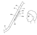
- FIG. 1 is a cross-sectional view illustrating a configuration example of a light emitting device 10 according to an embodiment.
- the person P views the light emission surface of the light emitting device 10 from a direction perpendicular to the substrate 100 of FIG.
- FIG. 2 is an enlarged view of the light emitting unit 140 of the light emitting device 10.
- the adhesive layer 210 and the sealing member 200 are omitted.
- the light emitting device 10 according to the embodiment is a lighting device or a display device. 1 and 2 show a case where the light emitting device 10 is a lighting device.
- the light emitting device 10 includes a light transmitting substrate 100, a plurality of light emitting portions 140, a light transmitting region, and an insulating film 150.
- the light emitting unit 140 is formed on the substrate 100, and includes a first electrode 110 having a light transmitting property, a second electrode 130 having a light reflecting property, and an organic layer 120 positioned between the first electrode 110 and the second electrode 130. .
- the translucent region is located between the plurality of light emitting units 140.
- the insulating film 150 defines an end 142 of the light emitting unit 140.
- the sealing member 200 is fixed to the light emitting unit 140 directly or via the adhesive layer 210.
- the side on which the substrate 100 is provided with reference to the light emitting unit 140 is referred to as the front surface of the light emitting device 10
- the side on which the sealing member 200 is provided is referred to as the back surface of the light emitting device 10.
- the light emitting device 10 is a lighting device, and includes a substrate 100, a plurality of light emitting units 140, and an insulating film 150.
- the substrate 100 is made of a light transmissive material.
- the plurality of light emitting units 140 are separated from each other, and all include the first electrode 110, the organic layer 120, and the second electrode 130.
- the first electrode 110 is a light-transmitting electrode
- the second electrode 130 is a light-shielding or light-reflecting electrode. At least a part of the first electrode 110 and the second electrode 130 overlap. However, a part of the region where the second electrode 130 is formed may be a translucent electrode.
- the organic layer 120 is located between the first electrode 110 and the second electrode 130.
- the insulating film 150 covers the edge of the first electrode 110. Further, at least a part of the insulating film 150 is not covered with the second electrode 130. Note that the second electrode 130 may cover the entire insulating film 150.
- the light emitting device 10 When viewed from a direction perpendicular to the substrate 100, the light emitting device 10 has a first region 102, a second region 104, and a third region 106 (translucent region).
- the first region 102 is a region overlapping with the second electrode 130. That is, the first region 102 is a region covered with the second electrode 130 when viewed from a direction perpendicular to the substrate 100.
- the second electrode 130 has reflectivity
- the first region 102 is a region that does not transmit light from the front surface to the back surface of the light emitting device 10 or the substrate 100 and from the back surface to the front surface.
- the second region 104 is a region that is not covered with the second electrode 130 but overlaps the insulating film 150.
- the third region 106 is a region that is not covered with the second electrode 130 and does not overlap with the insulating film 150 and is a light-transmitting region. And since the width
- the substrate 100 is, for example, a polygon such as a rectangle or a circle.
- the substrate 100 is formed using, for example, PEN (polyethylene naphthalate), PES (polyethersulfone), PET (polyethylene terephthalate), or polyimide.
- substrate 100 is not specifically limited, For example, it is 1.5 or more.
- an inorganic barrier film such as SiN x or SiON is formed on at least one surface (preferably both surfaces) of the substrate 100 in order to prevent moisture from permeating the substrate 100. It is preferable.
- an optical film such as an antireflection film may be provided on at least one surface of the substrate 100. In this case, as described later, the thickness including the inorganic barrier film and the optical film can be defined as the thickness d of the substrate 100.
- a light emitting unit 140 is formed on one surface of the substrate 100.
- the light emitting unit 140 has a configuration in which the first electrode 110, the organic layer 120, and the second electrode 130 are stacked in this order.
- the plurality of light emitting units 140 extend in a line shape.
- the plurality of light emitting units 140 are arranged so as to form a matrix, or form a segment or display a predetermined shape (for example, display icons). It may be.
- the plurality of light emitting units 140 are formed for each pixel.
- the first electrode 110 is a transparent electrode having optical transparency.
- the material of the transparent electrode is a metal-containing material, for example, a metal oxide such as ITO (Indium Tin Oxide), IZO (Indium Zinc Oxide), IWZO (Indium Tungsten Zinc Oxide), or ZnO (Zinc Oxide).
- the thickness of the first electrode 110 is, for example, not less than 10 nm and not more than 500 nm.
- the first electrode 110 is formed using, for example, a sputtering method or a vapor deposition method.
- the first electrode 110 may be a carbon nanotube or a conductive organic material such as PEDOT / PSS. In the drawing, a plurality of linear first electrodes 110 are formed on a substrate 100 in parallel with each other. For this reason, the first electrode 110 is not located in the second region 104 and the third region 106. Note that since the first electrode 110 is a transparent electrode having optical transparency, it may be positioned in the second region 104 and the third
- the first electrode 110 may be provided with an auxiliary electrode (not shown).
- the auxiliary electrode is formed in contact with the first electrode 110 with a material having a lower resistance value than the first electrode 110.
- the auxiliary electrode is formed using, for example, at least one metal layer.
- the auxiliary electrode is covered with an insulating film 150. For this reason, the auxiliary electrode is not directly connected to either the organic layer 120 or the second electrode 130. By providing the auxiliary electrode, the apparent resistance value of the first electrode 110 can be lowered.
- the organic layer 120 has a light emitting layer.
- the organic layer 120 has a configuration in which, for example, a hole injection layer, a light emitting layer, and an electron injection layer are stacked in this order.
- a hole transport layer may be formed between the hole injection layer and the light emitting layer.
- an electron transport layer may be formed between the light emitting layer and the electron injection layer.
- the organic layer 120 may be formed by a vapor deposition method.
- at least one layer of the organic layer 120, for example, a layer in contact with the first electrode 110, may be formed by a coating method such as an inkjet method, a printing method, or a spray method. In this case, the remaining layers of the organic layer 120 are formed by vapor deposition.
- all the layers of the organic layer 120 may be formed using the apply
- the second electrode 130 is made of, for example, a metal selected from the first group consisting of Al, Au, Ag, Pt, Mg, Sn, Zn, and In, or an alloy of a metal selected from the first group. Contains a metal layer. In this case, the second electrode 130 has a light shielding property.
- the thickness of the second electrode 130 is, for example, not less than 10 nm and not more than 500 nm. However, the second electrode 130 may be formed using the material exemplified as the material of the first electrode 110.
- the second electrode 130 is formed using, for example, a sputtering method or a vapor deposition method. In the example shown in this drawing, the light emitting device 10 has a plurality of linear second electrodes 130.
- the second electrode 130 is provided for each of the first electrodes 110 and is wider than the first electrode 110. For this reason, when viewed from the direction perpendicular to the substrate 100, the entire first electrode 110 is overlapped and covered by the second electrode 130 in the width direction.
- the first electrode 110 is wider than the second electrode 130, and when viewed from a direction perpendicular to the substrate 100, the entire second electrode 130 may be covered with the first electrode 110 in the width direction.
- the second electrode 130 may cover the entire insulating film 150, or the second electrode 130 may be provided so as to extend to a region where the first electrode 110 and the insulating film 150 are not formed. .
- the edge of the first electrode 110 is covered with an insulating film 150.
- the insulating film 150 is made of, for example, a photosensitive resin material such as polyimide, and surrounds a portion of the first electrode 110 that becomes the light emitting portion 140.
- An edge in the width direction of the second electrode 130 is located on the insulating film 150.
- a part of the insulating film 150 protrudes from the second electrode 130 when viewed from a direction perpendicular to the substrate 100.
- the organic layer 120 is also formed on the top and side surfaces of the insulating film 150. However, the organic layer 120 is divided between the adjacent light emitting units 140. Moreover, when the organic layer 120 has translucency, it does not need to be divided between the adjacent light emitting units 140.
- the light emitting device 10 includes the first region 102, the second region 104, and the third region 106.
- the first region 102 is a region overlapping with the second electrode 130.
- the second region 104 is a region that is not covered with the second electrode 130 but overlaps the insulating film 150.
- the organic layer 120 is also formed in the second region 104.
- the third region 106 is a region that is not covered with the second electrode 130 and does not overlap with the insulating film 150.
- the organic layer 120 is not formed in at least a part of the third region 106.
- the width of the second region 104 is narrower than the width of the third region 106.
- the width of the third region 106 may be wider or narrower than that of the first region 102.
- the width of the second region 104 is, for example, 0 or more (or more than 0) 0.2 or less
- the width of the third region 106 is, for example, 0.3 or more and 2 or less.
- the width of the first region 102 is, for example, 50 ⁇ m or more and 500 ⁇ m or less
- the width of the second region 104 is, for example, 0 ⁇ m or more (or more than 0 ⁇ m)
- the width of the third region 106 is, for example, 15 ⁇ m or more and 1000 ⁇ m or less. is there.
- the light emitting device 10 may include a coating film that directly covers the light emitting unit 140, the insulating film 150, and the substrate 100 in the translucent region.
- the coating film is, for example, the adhesive layer 210 or a sealing film described later.
- the sealing member 200 covers the light emitting unit 140 and the insulating film 150 and is fixed to the light emitting unit 140 directly or via the adhesive layer 210. No space (a layer other than solid) is interposed between the light emitting unit 140 and the sealing member 200.
- the sealing member 200 and the adhesive layer 210 are light transmissive. In the drawing, an example in which the sealing member 200 is fixed to the light emitting unit 140 via the adhesive layer 210 is shown.
- the sealing member 200 is formed of a light-transmitting thin plate (or foil) such as glass or a barrier film, for example. Yes.
- the edge of the sealing member 200 is fixed to the substrate 100 with an adhesive or the like.
- the adhesive layer 210 is made of an adhesive.
- the adhesive layer 210 is in contact with the second electrode 130 and is in contact with the sealing member 200.
- the sealing member 200 when the sealing member 200 is directly fixed to the light emitting unit 140, the sealing member 200 is formed by directly sealing the substrate 100 with a resin, for example.
- the sealing member 200 is in contact with the second electrode 130.
- the thickness of the sealing member 200 is not specifically limited, For example, they are 20 micrometers or more and 300 micrometers or less.
- FIG. 3 is a cross-sectional view showing another configuration example of the light emitting device 10. This figure corresponds to FIG. 1 described above.
- a sealing film 190 is formed as a coating film between the light emitting unit 140 and the adhesive layer 210.
- a barrier film 160 is further formed between the substrate 100 and the first electrode 110, between the light emitting unit 140 and the sealing member 200, and on the side of the sealing member 200 opposite to the light emitting unit 140. .
- the light emitting unit 140 is covered with the sealing film 190 and the barrier film 160.
- the sealing member 200 is fixed to the light emitting unit 140 via the barrier film 160, the sealing film 190, and the adhesive layer 210.
- the sealing film 190 is formed on at least a surface of the substrate 100 where the light emitting unit 140 is formed, and covers the light emitting unit 140. In the example of this figure, the sealing film 190 is in contact with the second electrode 130.
- the sealing film 190 is formed of, for example, an insulating material, more specifically, an inorganic material such as aluminum oxide or titanium oxide.
- the thickness of the sealing film 190 is preferably 300 nm or less. Moreover, the thickness of the sealing film 190 is, for example, 50 nm or more.
- the sealing film 190 is formed using, for example, an ALD (Atomic Layer Deposition) method. In this case, the step coverage of the sealing film 190 is increased.
- the sealing film 190 may have a multilayer structure in which a plurality of layers are stacked. In this case, it may have a structure in which a first sealing layer made of a first material (for example, aluminum oxide) and a second sealing layer made of a second material (for example, titanium oxide) are repeatedly stacked. .
- the lowermost layer may be either the first sealing layer or the second sealing layer.
- the uppermost layer may be either the first sealing layer or the second sealing layer.
- the sealing film 190 may be a single layer in which the first material and the second material are mixed.
- the sealing film 190 may be formed using other film forming methods such as a CVD method or a sputtering method.
- the sealing film 190 is formed of an insulating film such as SiO 2 or SiN, and the film thickness is, for example, not less than 10 nm and not more than 1000 nm.
- the barrier film 160 is formed using, for example, an ALD method, a CVD method, or a sputtering method.
- the barrier film 160 is formed of an insulating film such as Al 2 O 3 , SiO 2 , SiN, Si 3 N 4 , and the film thickness is, for example, 50 nm or more and 5000 nm or less.
- the barrier film 160 may have a multilayer structure in which a plurality of layers are stacked.
- the multilayer structure may include, for example, an organic planarization layer.
- one or more of the plurality of barrier films 160 and sealing films 190 may be omitted.
- the sealing member 200 is formed in contact with the sealing film 190, the sealing film 190 and the sealing member 200 can be regarded as a sealing member. In this case, it can be said that the sealing member is directly fixed to the light emitting unit 140.
- FIG. 4 is a plan view of the light emitting device 10. 1 corresponds to the AA section of FIG.
- the plurality of light emitting units 140 extend in the same direction when viewed from the direction perpendicular to the substrate 100.
- the first region 102, the second region 104, and the third region 106 are all linear and extend in the same direction.
- the second area 104, the first area 102, the second area 104, and the third area 106 are repeatedly arranged in this order.
- the direction perpendicular to the substrate 100 refers to a direction perpendicular to the main surface of the substrate 100.
- FIG. 5 is an enlarged view of a region surrounded by a broken line ⁇ in FIG.
- the back surface 109 of the substrate 100 is a surface facing the second region 104
- the front surface 108 of the substrate 100 is a surface opposite to the side facing the second region 104.
- an arrow L 1 indicates an example of an optical path taken by the light emitted from the light emitting unit 140 toward the front surface 108 of the substrate 100.
- An arrow L 2 indicates a path of light that is refracted and emitted to the outside of the light emitting device 10 out of the light reaching the front surface 108 of the substrate 100.
- a broken line arrow L 3 indicates a light path reflected toward the back surface side of the light emitting device 10 by being reflected at the interface between the substrate 100 and the air.
- the critical angle ⁇ c arcsin (1 / n) is established, where n is the refractive index of the substrate 100. If the surface of the substrate 100 is flat and does not scatter, the totally reflected light is emitted from the end portion without being taken out by either the front surface or the back surface. Therefore, the light does not leak on the back surface. On the other hand, some light of the critical angle theta c smaller than the incidence angle is taken out as output light, a portion is regularly reflected at the same angle. When the positive reflected light L 3 reaches the sealing member 200 or the adhesive layer 210, a part is emitted to the outside of the light emitting device 10, it becomes the backside leakage light.
- the ratio R is about 4%.
- This ratio R increases according to the Fresnel law as the incident angle ⁇ increases.
- the regular reflection ratio R is several percent, it is necessary to consider the influence on the back surface leakage light. This is because the regular reflection on the back surface 109 is also only a few percent, and most of the regular reflection light on the front surface 108 becomes the back surface leakage light as it is.
- the thickness d of the substrate 100 and the portion of the second electrode 130 outside the light emitting portion 140 relative to the end portion 142 (hereinafter referred to as “overlap region”). ),
- the relationship of d / 2 ⁇ W is established. Therefore, approximately 30% or more of the regularly reflected light on the front surface 108 is reflected again on the front surface 108 side in the overlap region, and the back surface leakage light can be reduced.
- W is the light emitting portion 140 rather than the end portion 142 of the second electrode 130 in a cross section perpendicular to the surface of the substrate 100 and perpendicular to the extending direction of the light emitting portion 140 (corresponding to the AA cross section in FIG. 4). It is the width of the outer part. The width W can also be said to be the shortest distance between the end of the light emitting unit 140 and the end of the second electrode 130.
- the thickness d of the substrate 100 can be defined as the distance between the surface of the first electrode 110 facing the substrate 100 and the surface exposed to the gas phase of the substrate 100 or a layer stacked on the substrate 100. That is, when a barrier layer, an optical film, or the like is laminated on at least one surface of the substrate 100, the thickness including the barrier layer or the optical film can be regarded as the thickness d.
- d ⁇ tan (arcsin (1 / n)) ⁇ W ⁇ 3d ⁇ tan (arcsin (1 / n)) is satisfied.
- FIG. 6 is a diagram illustrating an example of an optical path in the substrate 100 of the light emitted from the light emitting unit 140.
- the light emitting unit 140 is illustrated in a simplified manner.
- dotted arrows indicate the optical path of light totally reflected at the interface between the substrate 100 and air.
- W 1 can be said to be a distance in which light incident on the interface between the substrate 100 and the air at a critical angle travels in the in-plane direction of the substrate 100 while traveling from the back surface 109 to the front surface 108.
- the light from the light emitting unit 140 reaches the distance of 2 ⁇ W 1 , that is, 2d ⁇ tan (arcsin (1 / n)) from the end of the light emitting unit 140. Therefore, by setting d ⁇ tan (arcsin (1 / n)) ⁇ W, approximately 50% or more of the specularly reflected light is reflected again to the front surface 108 side in the overlap region, and back surface leakage Light can be further reduced.
- the light transmittance of the light emitting device 10 is not impaired.
- the thicknesses of the first electrode 110 and the insulating film 150 are negligible because they are sufficiently smaller than the thickness d of the substrate 100.
- the light emitting device 10 it is more preferable that 2d ⁇ tan (arcsin (1 / n)) ⁇ W ⁇ 3d ⁇ tan (arcsin (1 / n)) is satisfied. If so, almost all of the specularly reflected light below the critical angle is reflected again on the front surface 108 side in the overlap region, and the back surface leakage light can be further reduced. On the other hand, the light transmittance of the light emitting device 10 is not impaired.
- the refractive index of the thickest layer among the plurality of layers can be the refractive index n of the substrate.
- the average value of the plurality of layers may be the refractive index n of the substrate.
- At least one of a case where the refractive index of the thickest layer among the plurality of layers is n and a case where the average value of the plurality of layers is n is d ⁇ tan (arcsin (1 / n)) ⁇ W ⁇ It is more preferable that 3d ⁇ tan (arcsin (1 / n)) is satisfied, and it is more preferable that 2d ⁇ tan (arcsin (1 / n)) ⁇ W ⁇ 3 d ⁇ tan (arcsin (1 / n)) is satisfied.
- 1 and 2 show an example in which the width W of the left and right overlap regions for one light emitting unit 140 is the same, the width W of the plurality of overlap regions for one light emitting unit 140 is at least one.
- the parts may have different sizes.
- 1 and 2 show an example in which the width W of the overlap region is the same for the plurality of light emitting units 140, but the width W of the overlap region of the plurality of light emitting units 140 is at least partially. Different sizes may be used.
- the largest width W only needs to satisfy the relationship of d / 2 ⁇ W. More preferably, the smallest width W satisfies the relationship of d / 2 ⁇ W.
- the substrate 100 is a light-transmitting substrate such as a glass substrate or a resin substrate.
- the substrate 100 may have flexibility.
- the thickness d of the substrate 100 is not particularly limited, but is, for example, 10 ⁇ m or more and 1000 ⁇ m or less.
- the thickness d of the substrate 100 is preferably 100 ⁇ m or less.
- the first electrode 110 is formed on the substrate 100 by using, for example, a sputtering method.
- the first electrode 110 is formed into a predetermined pattern using, for example, a photolithography method.
- an inorganic barrier film may be formed on the surface of the substrate 100 by a sputtering method or the like before the first electrode 110 is formed.
- an insulating film 150 is formed on the edge of the first electrode 110.
- the insulating film 150 is formed of a photosensitive resin
- the insulating film 150 is formed in a predetermined pattern through an exposure and development process.
- the organic layer 120 and the second electrode 130 are formed in this order.
- the organic layer 120 includes a layer formed by an evaporation method
- this layer is formed in a predetermined pattern using, for example, a mask.
- the second electrode 130 is also formed in a predetermined pattern using, for example, a mask.
- the light emitting unit 140 is sealed using the sealing member 200.
- d / 2 ⁇ W is established between the thickness d of the substrate 100 and the width W of the second electrode 130 on the outer side of the light emitting unit 140 with respect to the end 142. Therefore, the reflected light from the surface of the substrate 100 can be further reflected to the substrate 100 side by the second electrode 130, and the back surface leakage light can be reduced.
- FIG. 7 is a cross-sectional view illustrating a configuration example of the light emitting system according to the first modification.
- the light emitting system includes the light emitting device 10 and the partition member 20 described above.
- the light emitting system includes a light transmissive partition member 20, a light transmissive substrate 100, a plurality of light emitting portions 140, a light transmissive region, an insulating film 150, and a coating film.
- the partition member 20 partitions the space from the outside.
- the substrate 100 is disposed on the partition member 20.
- the light emitting unit 140 is formed on one surface of the substrate 100.
- the light emitting unit 140 includes a first electrode 110 having a light transmitting property, a second electrode 130 having a light reflecting property, and an organic layer 120 positioned between the first electrode 110 and the second electrode 130.
- the translucent region is located between the plurality of light emitting units 140.
- the insulating film 150 defines an end 142 of the light emitting unit 140.
- the coating film directly covers the light emitting unit 140, the insulating film 150, and the substrate 100 in the translucent region.
- the partition member 20 has translucency and partitions the space from the outside. This space is, for example, a space where a person stays or a space where goods or the like are arranged.
- the light emitting device 10 has the same configuration as that of the above-described embodiment. In the example shown in the figure, the surface (first surface 100a) on the side where the light emitting unit 140 is provided in the substrate 100 faces the space where a person stays.
- the partition member 20 is, for example, a window of the moving body 30 for a person to move or a window of a showcase, and is formed using glass or translucent resin.
- the moving body 30 is, for example, a car, a train, or an airplane.
- the partition member 20 is a windshield, a rear glass, or a window glass (for example, a door glass) attached to the side of the seat.
- the plurality of light emitting units 140 function as, for example, brake lamps.
- the partition member 20 is a windshield or a rear glass
- the plurality of light emitting units 140 may be turn lamps.
- the partition member 20 may be a window that partitions the inside and the outside of a room such as a conference room.
- a light emitting system that can identify whether or not the conference room is used by turning on / off the light emitting unit 140 may be used.
- the second surface 100b of the light emitting device 10 is fixed to the inner surface (first surface 22) of the partition member 20 via the adhesive layer 300.
- the second surface 100b is a surface on the side opposite to the first surface 100a, and is a surface on the light extraction side.
- the light radiated from the light emitting unit 140 of the light emitting device 10 is radiated to the outside of the space (for example, the moving body 30) through the partition member 20.
- the light emitting device 10 is light transmissive. For this reason, a person can visually recognize the outside and the inside of the space through the partition member 20. For example, a person located inside the moving body 30 can visually recognize the outside of the moving body 30 through the partition member 20.
- the adhesive layer 300 fixes the light emitting device 10 to the partition member 20.
- the material for the adhesive layer 300 is not particularly limited as long as it has such a function.
- a part of the second surface 100 b of the substrate 100 (for example, two sides facing each other) is fixed to the first surface 22 of the partition member 20 via the adhesive layer 300. Therefore, an air gap is formed between the substrate 100 and the first surface 22.
- the reflected light from the surface of the substrate 100 is secondly reflected.
- the electrode 130 can be further reflected toward the substrate 100 side. Therefore, back surface leakage light can be reduced.
- FIG. 8 is a cross-sectional view illustrating a configuration example of a light emitting system according to the second modification.
- the light emitting system according to this modification is the same as the light emitting system according to modification 1 except that the light emitting device 10 is attached to the outer surface (second surface 24) of the moving body 30 in the partition member 20. It is the composition.
- the light emitting device 10 has the same configuration as the above-described embodiment.
- the surface opposite to the partition member 20 is a light extraction surface. In order to do so, the surface on the first surface 100a side of the light emitting device 10 may be opposed to the partition member 20.
- the light from the light emitting device 10 is directly emitted to the outside of the moving body 30 without passing through the partition member 20. For this reason, compared with the modification 1, the person outside the moving body 30 can easily recognize the light from the light emitting device 10. Further, since the light emitting device 10 is attached to the outside of the moving body 30, that is, the second surface 24 side of the partition member 20, the light emitted from the light emitting device 10 is reflected by the partition member 20 and enters the inside of the moving body 30. Can be suppressed.
- FIG. 9 is a cross-sectional view illustrating a configuration example of a light emitting system according to Modification 3.
- the light emitting system according to this modification has the same configuration as that of the light emitting system according to modification 1 except that the light emitting device 10 is fixed to the partition member 20 using the fixing member 310.
- the fixing member 310 is a frame-like member, and the lower surface is fixed to the partition member 20 using the adhesive layer 300.
- the upper part of the fixing member 310 is bent toward the inner side of the fixing member 310, and the edge of the light emitting device 10 is pressed by the bent part.
- the shape of the fixing member 310 is not limited to the example shown in this figure.
- a convex portion 101 is provided on the second surface 100b of the light emitting device 10 so as to surround the light emitting portion 140 when viewed from the direction perpendicular to the substrate 100. Therefore, an air gap is formed between the substrate 100 and the first surface 22 in a region overlapping with 140 when viewed from the direction perpendicular to the substrate.
- the convex portion 101 is made of, for example, a resin material. Even in such a case, in the light emitting device 10, since d / 2 ⁇ W is established between the thickness d of the substrate 100 and the width W of the overlap region, the reflected light from the surface of the substrate 100 is secondly reflected. The electrode 130 can be further reflected toward the substrate 100 side. Therefore, back surface leakage light can be reduced.
- FIG. 10 is a cross-sectional view showing another configuration example of the light emitting system according to the third modification.
- the partition member 20 may be curved in a direction that protrudes toward the outside of the moving body 30. In such a case, it is difficult to directly fix the light emitting device 10 on the flat plate to the inner surface (first surface 22) of the partition member 20. However, if the fixing member 310 is used, the light emitting device 10 can be fixed to the first surface 22 of the partition member 20 even in such a case.
- the substrate 100 may be provided with the convex portion 101 illustrated in FIG. 9 or may not be provided.
- FIG. 11 is a cross-sectional view illustrating a configuration example of a light emitting system according to Modification 4.
- the light emitting system according to the present modification has the same configuration as that of any of the first to third modifications described above, except that a plurality of light emitting devices 10 are attached to the partition member 20.
- FIG. 11 the example corresponding to FIG. 9 is simplified and shown.
- the plurality of light emitting devices 10 may be controlled to emit and extinguish according to the same control signal, or may be controlled to emit and extinguish according to different control signals.
- FIG. 12 is a cross-sectional view illustrating a configuration example of a light emitting system according to Modification 5.
- the light emitting system according to this modification has the same configuration as that of the light emitting system according to modification 1 except for the configuration of the partition member 20 and the position of the light emitting device 10.
- the partition member 20 has a configuration in which a plurality of light transmissive members 21 (for example, a glass plate or a resin plate) are stacked.
- the light emitting device 10 is attached to the partition member 20 by being sandwiched between the adjacent translucent members 21.
- a convex portion 101 is provided on the second surface 100b of the light emitting device 10 so as to surround the light emitting portion 140 when viewed from the direction perpendicular to the substrate 100. Therefore, an air gap is formed between the substrate 100 and the surface 211 of the translucent member 21 facing the substrate 100 in a region overlapping the light emitting unit 140 when viewed from the direction perpendicular to the substrate. Even in such a case, in the light emitting device 10, since d / 2 ⁇ W is established between the thickness d of the substrate 100 and the width W of the overlap region, the reflected light from the surface of the substrate 100 is secondly reflected. The electrode 130 can be further reflected toward the substrate 100 side. Therefore, back surface leakage light can be reduced.
- a light emitting device as shown in FIG. 3 was produced as follows. Specifically, first, a polyimide sheet provided with a barrier film was prepared as a substrate. Here, the refractive index of the polyimide sheet was 1.6, and the thickness of the substrate including the barrier film was 20 ⁇ m. Next, a light emitting portion was formed on the substrate. The width W of the overlap region was 20 ⁇ m. The formed light emitting part was covered with a sealing film, and the sealing member on which the barrier film was further formed was fixed to the light emitting part with an adhesive.
- a light emitting device was fabricated in the same manner as in the example except that glass having a refractive index of 1.5 and a thickness of 700 ⁇ m was used as the substrate.
- FIG. 13 is a diagram showing the results of measuring the relationship between the observation angle and the backside leakage light intensity for the light emitting devices of the above examples and comparative examples.
- the case of direct viewing from the direction perpendicular to the substrate on the back side is defined as an observation angle of 0 °, and the tilt angle from that direction is indicated as the observation angle.
- the emission intensity on the surface side was the same in the example and the comparative example.
Abstract
In this light-emitting device, light-emitting sections (140) are formed on a substrate (100) and each comprise a translucent first electrode (110), a light-reflective second electrode (130), and an organic layer (120) positioned between the first electrode (110) and the second electrode (130). A translucent region is positioned between the plurality of light-emitting sections (140). An insulating film (150) demarcates an end (142) of the light-emitting sections (140). A sealing member (200) is fixed to the light-emitting sections (140) either directly or via an adhesive layer (210). When the thickness of the substrate (100) is denoted by d and the width of a part of the second electrode (130) further outward on the light-emitting sections (140) than the end (142) is denoted by W, the expression d/2 ≤ W is satisfied.
Description
本発明は、発光装置および発光システムに関する。
The present invention relates to a light emitting device and a light emitting system.
近年は有機ELを利用した発光装置の開発が進んでいる。この発光装置は、照明装置や表示装置として使用されており、第1電極と第2電極の間に有機層を挟んだ構成を有している。そして、一般的には第1電極には透明材料が用いられており、第2電極には金属材料が用いられている。
In recent years, the development of light-emitting devices using organic EL has progressed. This light-emitting device is used as a lighting device or a display device, and has a configuration in which an organic layer is sandwiched between a first electrode and a second electrode. In general, a transparent material is used for the first electrode, and a metal material is used for the second electrode.
有機ELを利用した発光装置の一つに、特許文献1に記載の技術がある。特許文献1の技術は、有機ELを利用した表示装置に光透過性(シースルー)を持たせるために、第2電極を画素の一部にのみ設けている。このような構造において、複数の第2電極の間に位置する領域は光を透過させるため、表示装置は光透過性を有することができる。なお、特許文献1に記載の技術において、複数の第2電極の間には、画素を画定するために、透光性の絶縁膜が形成されている。特許文献1において、この絶縁膜の材料として、酸化シリコンなどの無機材料や、アクリル樹脂などの樹脂材料が例示されている。
One of light-emitting devices using organic EL is a technique described in Patent Document 1. In the technique of Patent Document 1, the second electrode is provided only in a part of the pixel so that the display device using the organic EL has light transmittance (see-through). In such a structure, since the region positioned between the plurality of second electrodes transmits light, the display device can have light transmittance. In the technique described in Patent Document 1, a light-transmitting insulating film is formed between the plurality of second electrodes in order to define pixels. Patent Document 1 exemplifies inorganic materials such as silicon oxide and resin materials such as acrylic resin as the material of the insulating film.
片面(おもて面)からのみ光を取り出したい透過型の発光装置において、逆側の面(裏面)からも一部の光が漏れ出てしまう場合がある。この場合、裏面側から発光装置を介して反対側を視認しにくくなったり、おもて面での光取り出し効率が低下したりする。
In a transmissive light-emitting device that wants to extract light only from one side (front surface), some light may leak out from the opposite side (back side). In this case, it is difficult to visually recognize the opposite side from the back side through the light emitting device, or the light extraction efficiency on the front side is reduced.
本発明が解決しようとする課題としては、透過型の発光装置において、発光面とは逆の面から光を漏れにくくすることが一例として挙げられる。
As a problem to be solved by the present invention, in a transmissive light emitting device, for example, it is difficult to leak light from a surface opposite to a light emitting surface.
請求項1に記載の発明は、
透光性の基板と、
前記基板に形成され、透光性の第1電極、光反射性の第2電極および、前記第1電極と前記第2電極との間に位置する有機層を有する複数の発光部と、
前記複数の発光部の間に位置する透光性領域と、
前記発光部の端部を画定する絶縁膜と、
を備え、
封止部材は、直接、又は接着層を介して前記発光部に固定されており、
前記基板の厚さをdとし、前記第2電極のうち前記端部よりも前記発光部の外側の部分の幅をWとしたとき、d/2≦Wが成り立つ発光装置である。 The invention described in claim 1
A translucent substrate;
A plurality of light-emitting portions formed on the substrate, each having a light-transmitting first electrode, a light-reflecting second electrode, and an organic layer positioned between the first electrode and the second electrode;
A translucent region located between the plurality of light emitting units;
An insulating film defining an end of the light emitting part;
With
The sealing member is fixed to the light emitting part directly or via an adhesive layer,
In the light emitting device, d / 2 ≦ W is satisfied, where d is a thickness of the substrate and W is a width of the second electrode outside the light emitting portion with respect to the end portion.
請求項9に記載の発明は、
空間を外部から仕切る透光性の仕切部材と、
前記仕切部材に配置された透光性の基板と、
前記基板の一方の面に形成され、透光性の第1電極、光反射性の第2電極および、前記第1電極と前記第2電極との間に位置する有機層を有する複数の発光部と、
前記複数の発光部の間に位置する透光性領域と、
前記発光部の端部を画定する絶縁膜と、
前記発光部、前記絶縁膜、および前記透光性領域の前記基板を直接被覆する被覆膜と、を備え、
前記基板の厚さをdとし、前記第2電極のうち前記端部よりも前記発光部の外側の部分の幅をWとしたとき、d/2≦Wが成り立つ発光システムである。 The invention according to claim 9 is:
A translucent partition member that partitions the space from the outside;
A translucent substrate disposed on the partition member;
A plurality of light emitting units formed on one surface of the substrate and having a translucent first electrode, a light reflecting second electrode, and an organic layer located between the first electrode and the second electrode When,
A translucent region located between the plurality of light emitting units;
An insulating film defining an end of the light emitting part;
The light emitting unit, the insulating film, and a coating film that directly covers the substrate of the light transmissive region,
In this light emitting system, d / 2 ≦ W is established, where d is the thickness of the substrate and W is the width of the second electrode outside the light emitting portion with respect to the end portion.
上述した目的、およびその他の目的、特徴および利点は、以下に述べる好適な実施の形態、およびそれに付随する以下の図面によってさらに明らかになる。
The above-described object and other objects, features, and advantages will be further clarified by a preferred embodiment described below and the following drawings attached thereto.
以下、本発明の実施の形態について、図面を用いて説明する。尚、すべての図面において、同様な構成要素には同様の符号を付し、適宜説明を省略する。
Hereinafter, embodiments of the present invention will be described with reference to the drawings. In all the drawings, the same reference numerals are given to the same components, and the description will be omitted as appropriate.
図1は、実施形態に係る発光装置10の構成例を示す断面図である。人物Pは、図1の基板100に垂直な方向から発光装置10の光射出面を見ている。図2は発光装置10の発光部140を拡大した図である。なお、本図において、接着層210および封止部材200は省略して描かれている。実施形態に係る発光装置10は、照明装置または表示装置である。図1及び図2は、発光装置10が照明装置である場合を示している。
FIG. 1 is a cross-sectional view illustrating a configuration example of a light emitting device 10 according to an embodiment. The person P views the light emission surface of the light emitting device 10 from a direction perpendicular to the substrate 100 of FIG. FIG. 2 is an enlarged view of the light emitting unit 140 of the light emitting device 10. In the drawing, the adhesive layer 210 and the sealing member 200 are omitted. The light emitting device 10 according to the embodiment is a lighting device or a display device. 1 and 2 show a case where the light emitting device 10 is a lighting device.
発光装置10は、透光性の基板100、複数の発光部140、透光性領域、および絶縁膜150を備える。発光部140は、基板100に形成され、透光性の第1電極110、光反射性の第2電極130および、第1電極110と第2電極130との間に位置する有機層120を有する。透光性領域は、複数の発光部140の間に位置する。絶縁膜150は、発光部140の端部142を画定する。封止部材200は、直接、又は接着層210を介して発光部140に固定されている。そして、基板100の厚さをdとし、第2電極130のうち端部142よりも発光部140の外側の部分の幅をWとしたとき、d/2≦Wが成り立つ。以下、詳細に説明する。
The light emitting device 10 includes a light transmitting substrate 100, a plurality of light emitting portions 140, a light transmitting region, and an insulating film 150. The light emitting unit 140 is formed on the substrate 100, and includes a first electrode 110 having a light transmitting property, a second electrode 130 having a light reflecting property, and an organic layer 120 positioned between the first electrode 110 and the second electrode 130. . The translucent region is located between the plurality of light emitting units 140. The insulating film 150 defines an end 142 of the light emitting unit 140. The sealing member 200 is fixed to the light emitting unit 140 directly or via the adhesive layer 210. When the thickness of the substrate 100 is d and the width of the portion of the second electrode 130 outside the light emitting portion 140 with respect to the end portion 142 is W, d / 2 ≦ W is satisfied. Details will be described below.
なお、以下では、発光部140を基準に基板100が設けられた側を発光装置10のおもて面、封止部材200が設けられた側を発光装置10の裏面と呼ぶ。
In the following, the side on which the substrate 100 is provided with reference to the light emitting unit 140 is referred to as the front surface of the light emitting device 10, and the side on which the sealing member 200 is provided is referred to as the back surface of the light emitting device 10.
本実施形態において、発光装置10は照明装置であり、基板100、複数の発光部140、及び絶縁膜150を備えている。基板100は透光性の材料が用いられている。複数の発光部140は互いに離間しており、いずれも、第1電極110、有機層120、及び第2電極130を有している。第1電極110は透光性の電極であり、第2電極130は遮光性あるいは光反射性を有する電極である。第1電極110と第2電極130の少なくとも一部が重なっている。ただし第2電極130の形成される領域の一部は透光性の電極であってもよい。有機層120は第1電極110と第2電極130の間に位置している。絶縁膜150は第1電極110の縁を覆っている。また、絶縁膜150の少なくとも一部は第2電極130で覆われていない。なお、第2電極130は、絶縁膜150の全体を覆っていても良い。
In this embodiment, the light emitting device 10 is a lighting device, and includes a substrate 100, a plurality of light emitting units 140, and an insulating film 150. The substrate 100 is made of a light transmissive material. The plurality of light emitting units 140 are separated from each other, and all include the first electrode 110, the organic layer 120, and the second electrode 130. The first electrode 110 is a light-transmitting electrode, and the second electrode 130 is a light-shielding or light-reflecting electrode. At least a part of the first electrode 110 and the second electrode 130 overlap. However, a part of the region where the second electrode 130 is formed may be a translucent electrode. The organic layer 120 is located between the first electrode 110 and the second electrode 130. The insulating film 150 covers the edge of the first electrode 110. Further, at least a part of the insulating film 150 is not covered with the second electrode 130. Note that the second electrode 130 may cover the entire insulating film 150.
そして、基板100に垂直な方向から見た場合において、発光装置10は、第1領域102、第2領域104、及び第3領域106(透光性領域)を有している。第1領域102は第2電極130と重なる領域である。つまり、第1領域102は基板100に垂直な方向から見た場合において、第2電極130に覆われている領域である。第2電極130が反射性を有している場合、第1領域102は、発光装置10または基板100の表面から裏面、及び裏面から表面のそれぞれにおいて光を通さない領域である。第2領域104は、第2電極130に覆われていないが、絶縁膜150と重なる領域である。第3領域106は、第2電極130に覆われておらず、絶縁膜150とも重ならない領域であり、透光性領域である。そして、第2領域104の幅は第3領域106の幅よりも狭いため、発光装置10は、十分な光透過性を有している。なお、第2領域104及び第3領域106によって透光性領域が形成されていてもよい。
When viewed from a direction perpendicular to the substrate 100, the light emitting device 10 has a first region 102, a second region 104, and a third region 106 (translucent region). The first region 102 is a region overlapping with the second electrode 130. That is, the first region 102 is a region covered with the second electrode 130 when viewed from a direction perpendicular to the substrate 100. When the second electrode 130 has reflectivity, the first region 102 is a region that does not transmit light from the front surface to the back surface of the light emitting device 10 or the substrate 100 and from the back surface to the front surface. The second region 104 is a region that is not covered with the second electrode 130 but overlaps the insulating film 150. The third region 106 is a region that is not covered with the second electrode 130 and does not overlap with the insulating film 150 and is a light-transmitting region. And since the width | variety of the 2nd area | region 104 is narrower than the width | variety of the 3rd area | region 106, the light-emitting device 10 has sufficient light transmittance. Note that a light-transmitting region may be formed by the second region 104 and the third region 106.
基板100は、例えば矩形などの多角形や円形である。基板100が樹脂基板である場合、基板100は、例えばPEN(ポリエチレンナフタレート)、PES(ポリエーテルサルホン)、PET(ポリエチレンテレフタラート)、又はポリイミドを用いて形成されている。基板100の屈折率nは特に限定されないが、たとえば1.5以上である。また、基板100が樹脂基板である場合、水分が基板100を透過することを抑制するために、基板100の少なくとも一面(好ましくは両面)に、SiNxやSiONなどの無機バリア膜が形成されているのが好ましい。また、基板100の少なくとも一面に反射防止膜等の光学フィルムを設けても良い。この場合、後述するように、無機バリア膜や光学フィルムを含んだ厚さを基板100の厚さdと定義することができる。
The substrate 100 is, for example, a polygon such as a rectangle or a circle. When the substrate 100 is a resin substrate, the substrate 100 is formed using, for example, PEN (polyethylene naphthalate), PES (polyethersulfone), PET (polyethylene terephthalate), or polyimide. Although the refractive index n of the board | substrate 100 is not specifically limited, For example, it is 1.5 or more. When the substrate 100 is a resin substrate, an inorganic barrier film such as SiN x or SiON is formed on at least one surface (preferably both surfaces) of the substrate 100 in order to prevent moisture from permeating the substrate 100. It is preferable. Further, an optical film such as an antireflection film may be provided on at least one surface of the substrate 100. In this case, as described later, the thickness including the inorganic barrier film and the optical film can be defined as the thickness d of the substrate 100.
基板100の一面には、発光部140が形成されている。発光部140は、第1電極110、有機層120、及び第2電極130をこの順に積層させた構成を有している。発光装置10が照明装置の場合、複数の発光部140はライン状に延在している。一方、発光装置10が表示装置の場合、複数の発光部140はマトリクスを構成するように配置されているか、セグメントを構成したり所定の形状を表示したりするように(例えばアイコンを表示するように)なっていてもよい。そして複数の発光部140は、画素別に形成されている。
A light emitting unit 140 is formed on one surface of the substrate 100. The light emitting unit 140 has a configuration in which the first electrode 110, the organic layer 120, and the second electrode 130 are stacked in this order. When the light emitting device 10 is an illumination device, the plurality of light emitting units 140 extend in a line shape. On the other hand, when the light emitting device 10 is a display device, the plurality of light emitting units 140 are arranged so as to form a matrix, or form a segment or display a predetermined shape (for example, display icons). It may be. The plurality of light emitting units 140 are formed for each pixel.
第1電極110は、光透過性を有する透明電極である。透明電極の材料は、金属を含む材料、例えば、ITO(Indium Tin Oxide)、IZO(Indium Zinc Oxide)、IWZO(Indium Tungsten Zinc Oxide)、ZnO(Zinc Oxide)等の金属酸化物である。第1電極110の厚さは、例えば10nm以上500nm以下である。第1電極110は、例えばスパッタリング法又は蒸着法を用いて形成される。なお、第1電極110は、カーボンナノチューブ、又はPEDOT/PSSなどの導電性有機材料であってもよい。本図において、基板100の上には、複数の線状の第1電極110が互いに平行に形成されている。このため、第2領域104及び第3領域106には第1電極110は位置していない。なお、第1電極110は光透過性を有する透明電極であるため、第2領域104及び第3領域106に位置しても良い。
The first electrode 110 is a transparent electrode having optical transparency. The material of the transparent electrode is a metal-containing material, for example, a metal oxide such as ITO (Indium Tin Oxide), IZO (Indium Zinc Oxide), IWZO (Indium Tungsten Zinc Oxide), or ZnO (Zinc Oxide). The thickness of the first electrode 110 is, for example, not less than 10 nm and not more than 500 nm. The first electrode 110 is formed using, for example, a sputtering method or a vapor deposition method. The first electrode 110 may be a carbon nanotube or a conductive organic material such as PEDOT / PSS. In the drawing, a plurality of linear first electrodes 110 are formed on a substrate 100 in parallel with each other. For this reason, the first electrode 110 is not located in the second region 104 and the third region 106. Note that since the first electrode 110 is a transparent electrode having optical transparency, it may be positioned in the second region 104 and the third region 106.
また、第1電極110には補助電極(不図示)が設けられていても良い。この場合、補助電極は、第1電極110よりも抵抗値が低い材料によって、第1電極110に接触して形成される。補助電極は例えば少なくとも一つの金属層を用いて形成される。また、補助電極は、絶縁膜150によって覆われている。このため、補助電極は有機層120及び第2電極130のいずれにも直接接続しない。補助電極を設けることにより第1電極110の見かけ上の抵抗値を低くすることができる。
Further, the first electrode 110 may be provided with an auxiliary electrode (not shown). In this case, the auxiliary electrode is formed in contact with the first electrode 110 with a material having a lower resistance value than the first electrode 110. The auxiliary electrode is formed using, for example, at least one metal layer. The auxiliary electrode is covered with an insulating film 150. For this reason, the auxiliary electrode is not directly connected to either the organic layer 120 or the second electrode 130. By providing the auxiliary electrode, the apparent resistance value of the first electrode 110 can be lowered.
有機層120は発光層を有している。有機層120は、例えば、正孔注入層、発光層、及び電子注入層をこの順に積層させた構成を有している。正孔注入層と発光層との間には正孔輸送層が形成されていてもよい。また、発光層と電子注入層との間には電子輸送層が形成されていてもよい。有機層120は蒸着法で形成されてもよい。また、有機層120のうち少なくとも一つの層、例えば第1電極110と接触する層は、インクジェット法、印刷法、又はスプレー法などの塗布法によって形成されてもよい。なお、この場合、有機層120の残りの層は、蒸着法によって形成されている。また、有機層120のすべての層が、塗布法を用いて形成されていてもよい。
The organic layer 120 has a light emitting layer. The organic layer 120 has a configuration in which, for example, a hole injection layer, a light emitting layer, and an electron injection layer are stacked in this order. A hole transport layer may be formed between the hole injection layer and the light emitting layer. In addition, an electron transport layer may be formed between the light emitting layer and the electron injection layer. The organic layer 120 may be formed by a vapor deposition method. In addition, at least one layer of the organic layer 120, for example, a layer in contact with the first electrode 110, may be formed by a coating method such as an inkjet method, a printing method, or a spray method. In this case, the remaining layers of the organic layer 120 are formed by vapor deposition. Moreover, all the layers of the organic layer 120 may be formed using the apply | coating method.
第2電極130は、例えば、Al、Au、Ag、Pt、Mg、Sn、Zn、及びInからなる第1群の中から選択される金属、又はこの第1群から選択される金属の合金からなる金属層を含んでいる。この場合、第2電極130は遮光性を有している。第2電極130の厚さは、例えば10nm以上500nm以下である。ただし、第2電極130は、第1電極110の材料として例示した材料を用いて形成されていてもよい。第2電極130は、例えばスパッタリング法又は蒸着法を用いて形成される。本図に示す例において、発光装置10は複数の線状の第2電極130を有している。第2電極130は、第1電極110のそれぞれに対して設けられており、かつ第1電極110よりも幅が広くなっている。このため、基板100に垂直な方向から見た場合において、幅方向において第1電極110の全体が第2電極130によって重なっており、また覆われている。また、第1電極110は、第2電極130よりも幅が広く、基板100に垂直な方向から見た場合、幅方向において第2電極130の全体が第1電極110によって覆われていてもよい。さらに、第2電極130は、絶縁膜150の全体を覆っていても良いし、第2電極130は、第1電極110も絶縁膜150も形成されていない領域まで広がって設けられていても良い。
The second electrode 130 is made of, for example, a metal selected from the first group consisting of Al, Au, Ag, Pt, Mg, Sn, Zn, and In, or an alloy of a metal selected from the first group. Contains a metal layer. In this case, the second electrode 130 has a light shielding property. The thickness of the second electrode 130 is, for example, not less than 10 nm and not more than 500 nm. However, the second electrode 130 may be formed using the material exemplified as the material of the first electrode 110. The second electrode 130 is formed using, for example, a sputtering method or a vapor deposition method. In the example shown in this drawing, the light emitting device 10 has a plurality of linear second electrodes 130. The second electrode 130 is provided for each of the first electrodes 110 and is wider than the first electrode 110. For this reason, when viewed from the direction perpendicular to the substrate 100, the entire first electrode 110 is overlapped and covered by the second electrode 130 in the width direction. The first electrode 110 is wider than the second electrode 130, and when viewed from a direction perpendicular to the substrate 100, the entire second electrode 130 may be covered with the first electrode 110 in the width direction. . Furthermore, the second electrode 130 may cover the entire insulating film 150, or the second electrode 130 may be provided so as to extend to a region where the first electrode 110 and the insulating film 150 are not formed. .
第1電極110の縁は、絶縁膜150によって覆われている。絶縁膜150は例えばポリイミドなどの感光性の樹脂材料によって形成されており、第1電極110のうち発光部140となる部分を囲んでいる。第2電極130の幅方向の縁は、絶縁膜150上に位置している。言い換えると、基板100に垂直な方向から見た場合において、絶縁膜150の一部は第2電極130からはみ出ている。また本図に示す例において、有機層120は絶縁膜150の上及び側面にも形成されている。ただし、有機層120は隣り合う発光部140の間で分断されている。また、有機層120が透光性を有する場合は、隣り合う発光部140の間で分断されていなくても良い。
The edge of the first electrode 110 is covered with an insulating film 150. The insulating film 150 is made of, for example, a photosensitive resin material such as polyimide, and surrounds a portion of the first electrode 110 that becomes the light emitting portion 140. An edge in the width direction of the second electrode 130 is located on the insulating film 150. In other words, a part of the insulating film 150 protrudes from the second electrode 130 when viewed from a direction perpendicular to the substrate 100. In the example shown in this drawing, the organic layer 120 is also formed on the top and side surfaces of the insulating film 150. However, the organic layer 120 is divided between the adjacent light emitting units 140. Moreover, when the organic layer 120 has translucency, it does not need to be divided between the adjacent light emitting units 140.
そして上記したように、発光装置10は第1領域102、第2領域104、及び第3領域106を有している。第1領域102は第2電極130と重なる領域である。第2領域104は、第2電極130に覆われていないが、絶縁膜150と重なる領域である。本図に示す例において、有機層120は第2領域104にも形成されている。第3領域106は、第2電極130に覆われておらず、絶縁膜150とも重ならない領域である。本図に示す例において、有機層120は第3領域106の少なくとも一部には形成されていない。そして第2領域104の幅は、第3領域106の幅よりも狭い。また第3領域106の幅は第1領域102の幅よりも広くてもよいし、狭くてもよい。第1領域102の幅を1とした場合、第2領域104の幅は例えば0以上(又は0超)0.2以下であり、第3領域106の幅は例えば0.3以上2以下である。また第1領域102の幅は、例えば50μm以上500μm以下であり、第2領域104の幅は例えば0μm以上(又は0μm超)100μm以下であり、第3領域106の幅は例えば15μm以上1000μm以下である。
As described above, the light emitting device 10 includes the first region 102, the second region 104, and the third region 106. The first region 102 is a region overlapping with the second electrode 130. The second region 104 is a region that is not covered with the second electrode 130 but overlaps the insulating film 150. In the example shown in this figure, the organic layer 120 is also formed in the second region 104. The third region 106 is a region that is not covered with the second electrode 130 and does not overlap with the insulating film 150. In the example shown in the drawing, the organic layer 120 is not formed in at least a part of the third region 106. The width of the second region 104 is narrower than the width of the third region 106. The width of the third region 106 may be wider or narrower than that of the first region 102. When the width of the first region 102 is 1, the width of the second region 104 is, for example, 0 or more (or more than 0) 0.2 or less, and the width of the third region 106 is, for example, 0.3 or more and 2 or less. . The width of the first region 102 is, for example, 50 μm or more and 500 μm or less, the width of the second region 104 is, for example, 0 μm or more (or more than 0 μm), 100 μm or less, and the width of the third region 106 is, for example, 15 μm or more and 1000 μm or less. is there.
また、発光装置10は、発光部140と、絶縁膜150と、透光性領域の基板100とを直接被覆する被覆膜を備えていても良い。被覆膜はたとえば接着層210または後述する封止膜である。
In addition, the light emitting device 10 may include a coating film that directly covers the light emitting unit 140, the insulating film 150, and the substrate 100 in the translucent region. The coating film is, for example, the adhesive layer 210 or a sealing film described later.
封止部材200は、発光部140および絶縁膜150を覆い、直接、又は接着層210を介して発光部140に固定されている。発光部140と封止部材200との間には、空間(固体以外の層)は介在しない。封止部材200および接着層210は光透過性を有する。本図では、封止部材200が接着層210を介して発光部140に固定されている例を示している。封止部材200が接着層210を介して発光部140に固定されている場合、封止部材200は、例えば、ガラス、又はバリアフィルムなどの光透過性の薄い板(又は箔)によって形成されている。そして封止部材200の縁は接着剤等で基板100に固定されている。これにより、封止部材200と基板100の間には、発光部140を収容する空間が形成される。そして、この空間がエポキシなどの接着剤で充填されている。この場合、接着剤により接着層210が構成される。本図の例では、接着層210は第2電極130に接しており、また、封止部材200に接している。
The sealing member 200 covers the light emitting unit 140 and the insulating film 150 and is fixed to the light emitting unit 140 directly or via the adhesive layer 210. No space (a layer other than solid) is interposed between the light emitting unit 140 and the sealing member 200. The sealing member 200 and the adhesive layer 210 are light transmissive. In the drawing, an example in which the sealing member 200 is fixed to the light emitting unit 140 via the adhesive layer 210 is shown. When the sealing member 200 is fixed to the light emitting unit 140 via the adhesive layer 210, the sealing member 200 is formed of a light-transmitting thin plate (or foil) such as glass or a barrier film, for example. Yes. The edge of the sealing member 200 is fixed to the substrate 100 with an adhesive or the like. Thereby, a space for accommodating the light emitting unit 140 is formed between the sealing member 200 and the substrate 100. This space is filled with an adhesive such as epoxy. In this case, the adhesive layer 210 is made of an adhesive. In the example of this figure, the adhesive layer 210 is in contact with the second electrode 130 and is in contact with the sealing member 200.
一方、封止部材200が直接、発光部140に固定されている場合、封止部材200はたとえば樹脂で基板100上を直接封止することで形成される。そして封止部材200は第2電極130に接する。この場合、封止部材200の厚さは特に限定されないが、例えば20μm以上300μm以下である。
On the other hand, when the sealing member 200 is directly fixed to the light emitting unit 140, the sealing member 200 is formed by directly sealing the substrate 100 with a resin, for example. The sealing member 200 is in contact with the second electrode 130. In this case, although the thickness of the sealing member 200 is not specifically limited, For example, they are 20 micrometers or more and 300 micrometers or less.
図3は、発光装置10の他の構成例を示す断面図である。本図は、上述した図1に相当する。本図の例において、発光部140と接着層210の間には被覆膜として封止膜190が形成されている。また、基板100と第1電極110の間、発光部140と封止部材200の間、および、封止部材200の、発光部140と反対の側には、さらにバリア膜160が形成されている。そして発光部140は封止膜190およびバリア膜160によって覆われている。本図の例では、封止部材200は、バリア膜160、封止膜190、および接着層210を介して発光部140に固定されている。
FIG. 3 is a cross-sectional view showing another configuration example of the light emitting device 10. This figure corresponds to FIG. 1 described above. In the example of this figure, a sealing film 190 is formed as a coating film between the light emitting unit 140 and the adhesive layer 210. Further, a barrier film 160 is further formed between the substrate 100 and the first electrode 110, between the light emitting unit 140 and the sealing member 200, and on the side of the sealing member 200 opposite to the light emitting unit 140. . The light emitting unit 140 is covered with the sealing film 190 and the barrier film 160. In the example of this figure, the sealing member 200 is fixed to the light emitting unit 140 via the barrier film 160, the sealing film 190, and the adhesive layer 210.
封止膜190は、基板100のうち、少なくとも発光部140が形成されている面に形成されており、発光部140を覆っている。本図の例において、封止膜190は第2電極130に接している。封止膜190は、例えば絶縁材料、さらに具体的には酸化アルミニウムや酸化チタンなどの無機材料によって形成される。また、封止膜190の厚さは、好ましくは300nm以下である。また封止膜190の厚さは、例えば50nm以上である。
The sealing film 190 is formed on at least a surface of the substrate 100 where the light emitting unit 140 is formed, and covers the light emitting unit 140. In the example of this figure, the sealing film 190 is in contact with the second electrode 130. The sealing film 190 is formed of, for example, an insulating material, more specifically, an inorganic material such as aluminum oxide or titanium oxide. The thickness of the sealing film 190 is preferably 300 nm or less. Moreover, the thickness of the sealing film 190 is, for example, 50 nm or more.
封止膜190は、例えばALD(Atomic Layer Deposition)法を用いて形成される。この場合、封止膜190の段差被覆性は高くなる。またこの場合、封止膜190は、複数の層を積層した多層構造を有していてもよい。この場合、第1の材料(例えば酸化アルミニウム)からなる第1封止層と、第2の材料(例えば酸化チタン)からなる第2封止層とを繰り返し積層した構造を有していてもよい。最下層は第1封止層及び第2封止層のいずれであってもよい。また、最上層も第1封止層及び第2封止層のいずれであってもよい。また、封止膜190は第1の材料と第2の材料の混在する単層であってもよい。
The sealing film 190 is formed using, for example, an ALD (Atomic Layer Deposition) method. In this case, the step coverage of the sealing film 190 is increased. In this case, the sealing film 190 may have a multilayer structure in which a plurality of layers are stacked. In this case, it may have a structure in which a first sealing layer made of a first material (for example, aluminum oxide) and a second sealing layer made of a second material (for example, titanium oxide) are repeatedly stacked. . The lowermost layer may be either the first sealing layer or the second sealing layer. Further, the uppermost layer may be either the first sealing layer or the second sealing layer. Further, the sealing film 190 may be a single layer in which the first material and the second material are mixed.
ただし、封止膜190は、他の成膜法、例えばCVD法やスパッタリング法を用いて形成されていてもよい。この場合、封止膜190は、SiO2、SiNなど絶縁膜によって形成されており、その膜厚は、例えば10nm以上1000nm以下である。
However, the sealing film 190 may be formed using other film forming methods such as a CVD method or a sputtering method. In this case, the sealing film 190 is formed of an insulating film such as SiO 2 or SiN, and the film thickness is, for example, not less than 10 nm and not more than 1000 nm.
バリア膜160は、たとえばALD法、CVD法やスパッタリング法を用いて形成される。バリア膜160は、Al2O3、SiO2、SiN、Si3N4など絶縁膜によって形成されており、その膜厚は、例えば50nm以上5000nm以下である。また、バリア膜160は、複数の層を積層した多層構造を有していてもよい。多層構造にはたとえば有機平坦化層が含まれて良い。
The barrier film 160 is formed using, for example, an ALD method, a CVD method, or a sputtering method. The barrier film 160 is formed of an insulating film such as Al 2 O 3 , SiO 2 , SiN, Si 3 N 4 , and the film thickness is, for example, 50 nm or more and 5000 nm or less. The barrier film 160 may have a multilayer structure in which a plurality of layers are stacked. The multilayer structure may include, for example, an organic planarization layer.
なお、本図の例において、複数のバリア膜160および封止膜190のうち一つ以上を省略しても良い。また、封止膜190上に接して封止部材200が形成される場合、封止膜190と封止部材200を合わせて封止部材とみなすことができる。この場合、封止部材は、直接、発光部140に固定されているといえる。
In the example of this figure, one or more of the plurality of barrier films 160 and sealing films 190 may be omitted. In the case where the sealing member 200 is formed in contact with the sealing film 190, the sealing film 190 and the sealing member 200 can be regarded as a sealing member. In this case, it can be said that the sealing member is directly fixed to the light emitting unit 140.
図4は発光装置10の平面図である。なお、図1は図4のA-A断面に対応している。本図に示す例において、複数の発光部140は、基板100に垂直な方向から見て同一方向に延在している。また、第1領域102、第2領域104、及び第3領域106は、いずれも線状かつ同一方向に延在している。そして本図及び図1に示すように、第2領域104、第1領域102、第2領域104、及び第3領域106が、この順に繰り返し並んでいる。なお、基板100に垂直な方向とは、基板100の主面に垂直な方向をいう。
FIG. 4 is a plan view of the light emitting device 10. 1 corresponds to the AA section of FIG. In the example shown in the figure, the plurality of light emitting units 140 extend in the same direction when viewed from the direction perpendicular to the substrate 100. The first region 102, the second region 104, and the third region 106 are all linear and extend in the same direction. As shown in FIG. 1 and FIG. 1, the second area 104, the first area 102, the second area 104, and the third area 106 are repeatedly arranged in this order. Note that the direction perpendicular to the substrate 100 refers to a direction perpendicular to the main surface of the substrate 100.
図5は、図1の破線αで囲んだ領域を拡大した図である。基板100の裏面109は第2領域104に対向する側の面であり、基板100のおもて面108は第2領域104に対向する側と反対側の面である。本図中L1の矢印は、発光部140から発せられた光が基板100のおもて面108に向かってとる光路の例を示す。また、L2の矢印は、基板100のおもて面108に至った光のうち、屈折して発光装置10の外部に放出される光の経路を示す。そして、L3の破線矢印は、基板100と空気の界面で反射されて発光装置10の裏面側に向かう光の経路を示す。
FIG. 5 is an enlarged view of a region surrounded by a broken line α in FIG. The back surface 109 of the substrate 100 is a surface facing the second region 104, and the front surface 108 of the substrate 100 is a surface opposite to the side facing the second region 104. In the drawing, an arrow L 1 indicates an example of an optical path taken by the light emitted from the light emitting unit 140 toward the front surface 108 of the substrate 100. An arrow L 2 indicates a path of light that is refracted and emitted to the outside of the light emitting device 10 out of the light reaching the front surface 108 of the substrate 100. A broken line arrow L 3 indicates a light path reflected toward the back surface side of the light emitting device 10 by being reflected at the interface between the substrate 100 and the air.
ここで、基板100の屈折率をnとしたとき、入射角が臨界角θcよりも大きい場合、光は全反射する。なお、基板100の屈折率をnとして、臨界角θc=arcsin(1/n)が成り立つ。このように全反射した光は、基板100の表面が平坦で散乱が無ければ、おもて面と裏面のどちらにも取り出されずに端部から出射する。したがって、裏面の漏れ光にはならない。一方で、臨界角θcより小さい入射角の光は一部が出射光として取り出され、一部は同じ角度で正反射する。この正反射した光L3が封止部材200または接着層210に到達すると、その一部が発光装置10の外に出射して、裏面漏れ光となってしまう。
Here, when the refractive index of the substrate 100 is n, when the angle of incidence is greater than the critical angle theta c, the light is totally reflected. Note that the critical angle θ c = arcsin (1 / n) is established, where n is the refractive index of the substrate 100. If the surface of the substrate 100 is flat and does not scatter, the totally reflected light is emitted from the end portion without being taken out by either the front surface or the back surface. Therefore, the light does not leak on the back surface. On the other hand, some light of the critical angle theta c smaller than the incidence angle is taken out as output light, a portion is regularly reflected at the same angle. When the positive reflected light L 3 reaches the sealing member 200 or the adhesive layer 210, a part is emitted to the outside of the light emitting device 10, it becomes the backside leakage light.
基板100の表面に対して正面から入射するとき、すなわち入射角θが0°のとき、入射光の強度に対する正反射の強度の比率Rはスネル則よりR=((n-1)/(n+1))2である。たとえば基板100が屈折率n=1.5のガラスの場合、比率Rは約4%となる。この比率Rは、入射角θが大きくなるにつれフレネル則に従い大きくなる。このように、正反射する比率Rが数%であったとしても、裏面漏れ光への影響を考える必要がある。裏面109での正反射も同じく数%しかなく、おもて面108での正反射光の大部分はそのまま裏面漏れ光となるからである。
When incident on the surface of the substrate 100 from the front, that is, when the incident angle θ is 0 °, the ratio R of the intensity of regular reflection to the intensity of incident light is R = ((n−1) / (n + 1) according to Snell's law. )) 2 . For example, when the substrate 100 is glass having a refractive index n = 1.5, the ratio R is about 4%. This ratio R increases according to the Fresnel law as the incident angle θ increases. Thus, even if the regular reflection ratio R is several percent, it is necessary to consider the influence on the back surface leakage light. This is because the regular reflection on the back surface 109 is also only a few percent, and most of the regular reflection light on the front surface 108 becomes the back surface leakage light as it is.
本実施形態に係る発光装置10では、上述のとおり、基板100の厚さdと、第2電極130のうち端部142よりも発光部140の外側の部分(以下、「オーバーラップ領域」と呼ぶ)の幅Wとの間にd/2≦Wの関係が成り立つ。したがって、おもて面108での正反射光のおよそ30%以上が、オーバーラップ領域で再度おもて面108側に反射されることとなり、裏面漏れ光を低減することができる。
In the light emitting device 10 according to the present embodiment, as described above, the thickness d of the substrate 100 and the portion of the second electrode 130 outside the light emitting portion 140 relative to the end portion 142 (hereinafter referred to as “overlap region”). ), The relationship of d / 2 ≦ W is established. Therefore, approximately 30% or more of the regularly reflected light on the front surface 108 is reflected again on the front surface 108 side in the overlap region, and the back surface leakage light can be reduced.
ここでWは、基板100の表面に垂直かつ発光部140の延在方向に垂直な断面(図4のA-A断面に相当)における、第2電極130のうち端部142よりも発光部140の外側の部分の幅である。また、幅Wは、発光部140の端部と第2電極130の端部との最短距離であるともいえる。一方、基板100の厚さdは、第1電極110の基板100に対向する面と、基板100または基板100と積層される層の気相に露出される面との距離と定義できる。すなわち、基板100の少なくとも一方の面にバリア層や光学フィルム等が積層されている場合には、そのバリア層や光学フィルムを含めた厚さを厚さdとみなすことができる。
Here, W is the light emitting portion 140 rather than the end portion 142 of the second electrode 130 in a cross section perpendicular to the surface of the substrate 100 and perpendicular to the extending direction of the light emitting portion 140 (corresponding to the AA cross section in FIG. 4). It is the width of the outer part. The width W can also be said to be the shortest distance between the end of the light emitting unit 140 and the end of the second electrode 130. On the other hand, the thickness d of the substrate 100 can be defined as the distance between the surface of the first electrode 110 facing the substrate 100 and the surface exposed to the gas phase of the substrate 100 or a layer stacked on the substrate 100. That is, when a barrier layer, an optical film, or the like is laminated on at least one surface of the substrate 100, the thickness including the barrier layer or the optical film can be regarded as the thickness d.
また、発光装置10においては、d×tan(arcsin(1/n))≦W<3d×tan(arcsin(1/n))が満たされることがより好ましい。
Further, in the light emitting device 10, it is more preferable that d × tan (arcsin (1 / n)) ≦ W <3d × tan (arcsin (1 / n)) is satisfied.
図6は、発光部140から発せられた光の、基板100内での光路の例を示す図である。本図において、発光部140は簡略化して描いている。また、本図中、点線の矢印は基板100と空気との界面で全反射する光の光路を示している。そして、本図においてW1で示す長さがd×tan(arcsin(1/n))である。すなわち、W1=d×tanθcが成り立ち、臨界角θc=arcsin(1/n)であるため、W1=d×tan(arcsin(1/n))が成り立つ。なお、W1は、臨界角で基板100と空気の界面に入射する光が基板100を裏面109からおもて面108まで進む間に基板100の面内方向に進む距離であると言える。そして本図の様に、発光部140からの光は発光部140の端部から2×W1、すなわち2d×tan(arcsin(1/n))の距離の範囲まで到達することが分かる。したがって、d×tan(arcsin(1/n))≦Wとすることで、正反射光のおよそ50%以上が、オーバーラップ領域で再度おもて面108側に反射されることとなり、裏面漏れ光をより低減することができる。一方で、W<3d×tan(arcsin(1/n))とすることにより、発光装置10の光透過性を損なうことがない。なおここでは、第1電極110や絶縁膜150の厚さは基板100の厚さdに対して十分小さいので無視できる。
FIG. 6 is a diagram illustrating an example of an optical path in the substrate 100 of the light emitted from the light emitting unit 140. In the drawing, the light emitting unit 140 is illustrated in a simplified manner. In the drawing, dotted arrows indicate the optical path of light totally reflected at the interface between the substrate 100 and air. Then, it is the length shown by W 1 is d × numeral tan (arcsin (1 / n) ). That is, since W 1 = d × tan θ c holds and the critical angle θ c = arcsin (1 / n), W 1 = d × tan (arcsin (1 / n)) holds. Note that W 1 can be said to be a distance in which light incident on the interface between the substrate 100 and the air at a critical angle travels in the in-plane direction of the substrate 100 while traveling from the back surface 109 to the front surface 108. As shown in the figure, it can be seen that the light from the light emitting unit 140 reaches the distance of 2 × W 1 , that is, 2d × tan (arcsin (1 / n)) from the end of the light emitting unit 140. Therefore, by setting d × tan (arcsin (1 / n)) ≦ W, approximately 50% or more of the specularly reflected light is reflected again to the front surface 108 side in the overlap region, and back surface leakage Light can be further reduced. On the other hand, by setting W <3d × tan (arcsin (1 / n)), the light transmittance of the light emitting device 10 is not impaired. Here, the thicknesses of the first electrode 110 and the insulating film 150 are negligible because they are sufficiently smaller than the thickness d of the substrate 100.
発光装置10においては、2d×tan(arcsin(1/n))≦W<3d×tan(arcsin(1/n))を満たすことがさらに好ましい。そうであれば、臨界角以下の正反射光のほぼ全てが、オーバーラップ領域で再度おもて面108側に反射されることとなり、裏面漏れ光をさらに低減することができる。一方で、発光装置10の光透過性を損なうことがない。
In the light emitting device 10, it is more preferable that 2d × tan (arcsin (1 / n)) ≦ W <3d × tan (arcsin (1 / n)) is satisfied. If so, almost all of the specularly reflected light below the critical angle is reflected again on the front surface 108 side in the overlap region, and the back surface leakage light can be further reduced. On the other hand, the light transmittance of the light emitting device 10 is not impaired.
なお、基板100の少なくとも一方の面にバリア層等が一層以上積層されている場合、それらを合わせて複数の層からなる基板ということができる。この場合、複数の層のうち最も厚い層の屈折率を、基板の屈折率nとすることができる。また、複数の層の平均値を基板の屈折率nとしても良い。複数の層のうち最も厚い層の屈折率をnとした場合と、複数の層の平均値をnとした場合のうち、少なくとも一方において、d×tan(arcsin(1/n))≦W<3d×tan(arcsin(1/n))を満たすことがさらに好ましく、2d×tan(arcsin(1/n))≦W<3d×tan(arcsin(1/n))を満たすことがより好ましい。
Note that in the case where one or more barrier layers or the like are stacked on at least one surface of the substrate 100, it can be said that they are combined to form a substrate composed of a plurality of layers. In this case, the refractive index of the thickest layer among the plurality of layers can be the refractive index n of the substrate. The average value of the plurality of layers may be the refractive index n of the substrate. At least one of a case where the refractive index of the thickest layer among the plurality of layers is n and a case where the average value of the plurality of layers is n is d × tan (arcsin (1 / n)) ≦ W < It is more preferable that 3d × tan (arcsin (1 / n)) is satisfied, and it is more preferable that 2d × tan (arcsin (1 / n)) ≦ W <3 d × tan (arcsin (1 / n)) is satisfied.
なお、図1および図2では、一つの発光部140に対する左右のオーバーラップ領域の幅Wが同じ場合の例を示したが、一つの発光部140に対する複数のオーバーラップ領域の幅Wは少なくとも一部が異なる大きさであっても良い。また、図1および図2では、複数の発光部140について、オーバーラップ領域の幅Wが全て同じ場合の例を示したが、複数の発光部140のオーバーラップ領域の幅Wは少なくとも一部が異なる大きさであっても良い。幅Wが異なる複数のオーバーラップがある場合、最も大きな幅Wがd/2≦Wの関係を満たせばよい。また、最も小さな幅Wがd/2≦Wの関係を満たすことがより好ましい。
1 and 2 show an example in which the width W of the left and right overlap regions for one light emitting unit 140 is the same, the width W of the plurality of overlap regions for one light emitting unit 140 is at least one. The parts may have different sizes. 1 and 2 show an example in which the width W of the overlap region is the same for the plurality of light emitting units 140, but the width W of the overlap region of the plurality of light emitting units 140 is at least partially. Different sizes may be used. When there are a plurality of overlaps having different widths W, the largest width W only needs to satisfy the relationship of d / 2 ≦ W. More preferably, the smallest width W satisfies the relationship of d / 2 ≦ W.
基板100は、例えばガラス基板や樹脂基板などの透光性を有する基板である。基板100は可撓性を有していてもよい。可撓性を有している場合、基板100の厚さdは、特に限定されないが、例えば10μm以上1000μm以下である。特に、基板100の厚さdは、100μm以下であることが好ましい。基板100の厚さdが100μm以下であれば、d/2≦Wを満たす場合でもオーバーラップ領域が大きくなりすぎず、発光装置10の良好な光透過性を確保することができる。
The substrate 100 is a light-transmitting substrate such as a glass substrate or a resin substrate. The substrate 100 may have flexibility. In the case of flexibility, the thickness d of the substrate 100 is not particularly limited, but is, for example, 10 μm or more and 1000 μm or less. In particular, the thickness d of the substrate 100 is preferably 100 μm or less. When the thickness d of the substrate 100 is 100 μm or less, even when d / 2 ≦ W is satisfied, the overlap region does not become too large, and good light transmittance of the light emitting device 10 can be ensured.
次に、発光装置10の製造方法について説明する。まず、基板100に第1電極110を、例えばスパッタリング法を用いて形成する。次いで、第1電極110を例えばフォトリソグラフィー法を利用して所定のパターンにする。なお、第1電極110を形成する前に、無機バリア膜をスパッタ法等により基板100の表面に形成しても良い。
Next, a method for manufacturing the light emitting device 10 will be described. First, the first electrode 110 is formed on the substrate 100 by using, for example, a sputtering method. Next, the first electrode 110 is formed into a predetermined pattern using, for example, a photolithography method. Note that an inorganic barrier film may be formed on the surface of the substrate 100 by a sputtering method or the like before the first electrode 110 is formed.
次いで、第1電極110の縁の上に絶縁膜150を形成する。例えば絶縁膜150が感光性の樹脂で形成されている場合、絶縁膜150は、露光及び現像工程を経ることにより、所定のパターンに形成される。次いで、有機層120及び第2電極130をこの順に形成する。有機層120が蒸着法で形成される層を含む場合、この層は、例えばマスクを用いるなどして所定のパターンに形成される。第2電極130も、例えばマスクを用いるなどして所定のパターンに形成される。その後、封止部材200を用いて発光部140を封止する。
Next, an insulating film 150 is formed on the edge of the first electrode 110. For example, when the insulating film 150 is formed of a photosensitive resin, the insulating film 150 is formed in a predetermined pattern through an exposure and development process. Next, the organic layer 120 and the second electrode 130 are formed in this order. When the organic layer 120 includes a layer formed by an evaporation method, this layer is formed in a predetermined pattern using, for example, a mask. The second electrode 130 is also formed in a predetermined pattern using, for example, a mask. Thereafter, the light emitting unit 140 is sealed using the sealing member 200.
本実施形態によれば、基板100の厚さdと、第2電極130のうち端部142よりも発光部140の外側の部分の幅Wとの間に、d/2≦Wが成り立つ。したがって、基板100表面からの反射光を第2電極130でさらに基板100側に反射させ、裏面漏れ光を低減することができる。
According to the present embodiment, d / 2 ≦ W is established between the thickness d of the substrate 100 and the width W of the second electrode 130 on the outer side of the light emitting unit 140 with respect to the end 142. Therefore, the reflected light from the surface of the substrate 100 can be further reflected to the substrate 100 side by the second electrode 130, and the back surface leakage light can be reduced.
(変形例1)
図7は、変形例1に係る発光システムについての構成例を示す断面図である。この発光システムは、上述した発光装置10及び仕切部材20を有している。具体的には、発光システムは、透光性の仕切部材20、透光性の基板100、複数の発光部140、透光性領域、絶縁膜150、および被覆膜を備える。仕切部材20は、空間を外部から仕切る。基板100は、仕切部材20に配置されている。発光部140は、基板100の一方の面に形成されている。また、発光部140は、透光性の第1電極110、光反射性の第2電極130および、第1電極110と第2電極130との間に位置する有機層120を有する。透光性領域は、複数の発光部140の間に位置する。絶縁膜150は、発光部140の端部142を画定する。被覆膜は、発光部140と、絶縁膜150と、透光性領域の基板100とを直接被覆する。そして、基板100の厚さをdとし、第2電極130のうち端部142よりも発光部140の外側の部分の幅をWとしたとき、d/2≦Wが成り立つ。以下に詳しく説明する。 (Modification 1)
FIG. 7 is a cross-sectional view illustrating a configuration example of the light emitting system according to the first modification. The light emitting system includes thelight emitting device 10 and the partition member 20 described above. Specifically, the light emitting system includes a light transmissive partition member 20, a light transmissive substrate 100, a plurality of light emitting portions 140, a light transmissive region, an insulating film 150, and a coating film. The partition member 20 partitions the space from the outside. The substrate 100 is disposed on the partition member 20. The light emitting unit 140 is formed on one surface of the substrate 100. In addition, the light emitting unit 140 includes a first electrode 110 having a light transmitting property, a second electrode 130 having a light reflecting property, and an organic layer 120 positioned between the first electrode 110 and the second electrode 130. The translucent region is located between the plurality of light emitting units 140. The insulating film 150 defines an end 142 of the light emitting unit 140. The coating film directly covers the light emitting unit 140, the insulating film 150, and the substrate 100 in the translucent region. When the thickness of the substrate 100 is d and the width of the portion of the second electrode 130 outside the light emitting portion 140 with respect to the end portion 142 is W, d / 2 ≦ W is satisfied. This will be described in detail below.
図7は、変形例1に係る発光システムについての構成例を示す断面図である。この発光システムは、上述した発光装置10及び仕切部材20を有している。具体的には、発光システムは、透光性の仕切部材20、透光性の基板100、複数の発光部140、透光性領域、絶縁膜150、および被覆膜を備える。仕切部材20は、空間を外部から仕切る。基板100は、仕切部材20に配置されている。発光部140は、基板100の一方の面に形成されている。また、発光部140は、透光性の第1電極110、光反射性の第2電極130および、第1電極110と第2電極130との間に位置する有機層120を有する。透光性領域は、複数の発光部140の間に位置する。絶縁膜150は、発光部140の端部142を画定する。被覆膜は、発光部140と、絶縁膜150と、透光性領域の基板100とを直接被覆する。そして、基板100の厚さをdとし、第2電極130のうち端部142よりも発光部140の外側の部分の幅をWとしたとき、d/2≦Wが成り立つ。以下に詳しく説明する。 (Modification 1)
FIG. 7 is a cross-sectional view illustrating a configuration example of the light emitting system according to the first modification. The light emitting system includes the
仕切部材20は透光性を有しており、空間を外部から仕切っている。この空間は、例えば人が滞在する空間、又は商品等のものが配置されている空間である。発光装置10は、上記した実施形態と同様の構成を有している。本図に示す例において、基板100のうち発光部140が設けられている側の面(第1面100a)は、人が滞在する空間を向いている。
The partition member 20 has translucency and partitions the space from the outside. This space is, for example, a space where a person stays or a space where goods or the like are arranged. The light emitting device 10 has the same configuration as that of the above-described embodiment. In the example shown in the figure, the surface (first surface 100a) on the side where the light emitting unit 140 is provided in the substrate 100 faces the space where a person stays.
仕切部材20は、例えば人が移動するための移動体30の窓、又はショーケースの窓であり、ガラス又は透光性の樹脂を用いて形成されている。移動体30は、例えば自動車、列車、又は飛行機である。移動体30が自動車の場合、仕切部材20はフロントガラス、リアガラス、又は座席の横に取り付けられた窓ガラス(例えばドアガラス)である。仕切部材20がリアガラスの場合、複数の発光部140は例えばブレーキランプとして機能する。また、仕切部材20がフロントガラス又はリアガラスの場合、複数の発光部140はターンランプであってもよい。また、仕切部材20は、会議室などの部屋の内部と外部を仕切る窓であってもよい。発光部140の点灯/非点灯により、会議室を利用しているか否かを識別できる発光システムでも良い。
The partition member 20 is, for example, a window of the moving body 30 for a person to move or a window of a showcase, and is formed using glass or translucent resin. The moving body 30 is, for example, a car, a train, or an airplane. When the moving body 30 is an automobile, the partition member 20 is a windshield, a rear glass, or a window glass (for example, a door glass) attached to the side of the seat. When the partition member 20 is rear glass, the plurality of light emitting units 140 function as, for example, brake lamps. Further, when the partition member 20 is a windshield or a rear glass, the plurality of light emitting units 140 may be turn lamps. Moreover, the partition member 20 may be a window that partitions the inside and the outside of a room such as a conference room. A light emitting system that can identify whether or not the conference room is used by turning on / off the light emitting unit 140 may be used.
そして、発光装置10の第2面100bは、接着層300を介して仕切部材20の内面(第1面22)に固定されている。ここで、第2面100bは、第1面100aとは反対側の面であり、光取出側の面である。このため、発光装置10の発光部140から放射された光は、仕切部材20を介して上記した空間(例えば移動体30)の外部に放射される。一方、発光装置10は光透過性を有している。このため、人は、仕切部材20を介して空間の外部や内部を視認することができる。例えば移動体30の内側に位置する人は、仕切部材20を介して移動体30の外部を視認することができる。
The second surface 100b of the light emitting device 10 is fixed to the inner surface (first surface 22) of the partition member 20 via the adhesive layer 300. Here, the second surface 100b is a surface on the side opposite to the first surface 100a, and is a surface on the light extraction side. For this reason, the light radiated from the light emitting unit 140 of the light emitting device 10 is radiated to the outside of the space (for example, the moving body 30) through the partition member 20. On the other hand, the light emitting device 10 is light transmissive. For this reason, a person can visually recognize the outside and the inside of the space through the partition member 20. For example, a person located inside the moving body 30 can visually recognize the outside of the moving body 30 through the partition member 20.
接着層300は発光装置10を仕切部材20に固定している。このような機能を果たす材料であれば、接着層300の材料はとくに限定はされない。本変形例において、基板100の第2面100bの一部(例えば互いに対向する2辺)が、接着層300を介して仕切部材20の第1面22に固定されている。したがって、基板100と第1面22との間にはエアギャップが形成されている。この様な場合でも、発光装置10において、基板100の厚さdと、オーバーラップ領域の幅Wとの間に、d/2≦Wが成り立つことにより、基板100表面からの反射光を第2電極130でさらに基板100側に反射させることができる。よって、裏面漏れ光を低減することができる。
The adhesive layer 300 fixes the light emitting device 10 to the partition member 20. The material for the adhesive layer 300 is not particularly limited as long as it has such a function. In this modification, a part of the second surface 100 b of the substrate 100 (for example, two sides facing each other) is fixed to the first surface 22 of the partition member 20 via the adhesive layer 300. Therefore, an air gap is formed between the substrate 100 and the first surface 22. Even in such a case, in the light emitting device 10, since d / 2 ≦ W is established between the thickness d of the substrate 100 and the width W of the overlap region, the reflected light from the surface of the substrate 100 is secondly reflected. The electrode 130 can be further reflected toward the substrate 100 side. Therefore, back surface leakage light can be reduced.
(変形例2)
図8は、変形例2に係る発光システムの構成例を示す断面図である。本変形例に係る発光システムは、発光装置10が仕切部材20のうち移動体30の外側の面(第2面24)に取り付けられている点を除いて、変形例1に係る発光システムと同様の構成である。 (Modification 2)
FIG. 8 is a cross-sectional view illustrating a configuration example of a light emitting system according to the second modification. The light emitting system according to this modification is the same as the light emitting system according to modification 1 except that thelight emitting device 10 is attached to the outer surface (second surface 24) of the moving body 30 in the partition member 20. It is the composition.
図8は、変形例2に係る発光システムの構成例を示す断面図である。本変形例に係る発光システムは、発光装置10が仕切部材20のうち移動体30の外側の面(第2面24)に取り付けられている点を除いて、変形例1に係る発光システムと同様の構成である。 (Modification 2)
FIG. 8 is a cross-sectional view illustrating a configuration example of a light emitting system according to the second modification. The light emitting system according to this modification is the same as the light emitting system according to modification 1 except that the
本変形例に係る発光装置10は、上記した実施形態と同じ構成を有している。ただし、発光装置10は、仕切部材20とは逆側の面が光取出面となっている。このようにするためには、発光装置10の第1面100a側の面を仕切部材20に対向させればよい。
The light emitting device 10 according to this modification has the same configuration as the above-described embodiment. However, in the light emitting device 10, the surface opposite to the partition member 20 is a light extraction surface. In order to do so, the surface on the first surface 100a side of the light emitting device 10 may be opposed to the partition member 20.
本変形例によっても、実施形態と同様に、裏面漏れ光を低減することができる。
Also according to this modification, it is possible to reduce backside leakage light as in the embodiment.
また、発光装置10からの光は仕切部材20を介さずに直接移動体30の外部に放射される。このため、変形例1と比較して、移動体30の外部にいる人は発光装置10からの光を認識しやすい。また、移動体30の外部すなわち仕切部材の20の第2面24側に発光装置10を取り付けているので、発光装置10の発光が仕切部材20で反射して移動体30の内部へ入ることを抑制できる。
Further, the light from the light emitting device 10 is directly emitted to the outside of the moving body 30 without passing through the partition member 20. For this reason, compared with the modification 1, the person outside the moving body 30 can easily recognize the light from the light emitting device 10. Further, since the light emitting device 10 is attached to the outside of the moving body 30, that is, the second surface 24 side of the partition member 20, the light emitted from the light emitting device 10 is reflected by the partition member 20 and enters the inside of the moving body 30. Can be suppressed.
(変形例3)
図9は、変形例3に係る発光システムの構成例を示す断面図である。本変形例に係る発光システムは、固定部材310を用いて発光装置10を仕切部材20に固定している点を除いて、変形例1に係る発光システムと同様の構成である。 (Modification 3)
FIG. 9 is a cross-sectional view illustrating a configuration example of a light emitting system according to Modification 3. The light emitting system according to this modification has the same configuration as that of the light emitting system according to modification 1 except that thelight emitting device 10 is fixed to the partition member 20 using the fixing member 310.
図9は、変形例3に係る発光システムの構成例を示す断面図である。本変形例に係る発光システムは、固定部材310を用いて発光装置10を仕切部材20に固定している点を除いて、変形例1に係る発光システムと同様の構成である。 (Modification 3)
FIG. 9 is a cross-sectional view illustrating a configuration example of a light emitting system according to Modification 3. The light emitting system according to this modification has the same configuration as that of the light emitting system according to modification 1 except that the
固定部材310は枠状の部材であり、下面が接着層300を用いて仕切部材20に固定されている。固定部材310の上部は固定部材310の内側に向けて折れ曲がっており、この折れ曲がっている部分で発光装置10の縁を押さえている。ただし、固定部材310の形状は本図に示す例に限定されない。
The fixing member 310 is a frame-like member, and the lower surface is fixed to the partition member 20 using the adhesive layer 300. The upper part of the fixing member 310 is bent toward the inner side of the fixing member 310, and the edge of the light emitting device 10 is pressed by the bent part. However, the shape of the fixing member 310 is not limited to the example shown in this figure.
本変形例において、発光装置10の第2面100bには、基板100に垂直な方向から見て発光部140を囲むように凸部101が設けられている。したがって、基板に垂直な方向から見て140と重なる領域において、基板100と第1面22との間にはエアギャップが形成されている。凸部101はたとえば樹脂材料により形成される。この様な場合でも、発光装置10において、基板100の厚さdと、オーバーラップ領域の幅Wとの間に、d/2≦Wが成り立つことにより、基板100表面からの反射光を第2電極130でさらに基板100側に反射させることができる。よって、裏面漏れ光を低減することができる。
In this modification, a convex portion 101 is provided on the second surface 100b of the light emitting device 10 so as to surround the light emitting portion 140 when viewed from the direction perpendicular to the substrate 100. Therefore, an air gap is formed between the substrate 100 and the first surface 22 in a region overlapping with 140 when viewed from the direction perpendicular to the substrate. The convex portion 101 is made of, for example, a resin material. Even in such a case, in the light emitting device 10, since d / 2 ≦ W is established between the thickness d of the substrate 100 and the width W of the overlap region, the reflected light from the surface of the substrate 100 is secondly reflected. The electrode 130 can be further reflected toward the substrate 100 side. Therefore, back surface leakage light can be reduced.
図10は、変形例3に係る発光システムの他の構成例を示す断面図である。本図に示すように、移動体30の外側に向けて凸になる方向に仕切部材20が湾曲している場合がある。このような場合において、平板上の発光装置10を仕切部材20の内面(第1面22)に直接固定することは難しい。しかし、固定部材310を用いると、このような場合でも発光装置10を仕切部材20の第1面22に固定することができる。なお、基板100には、図9に示した凸部101が設けられていても良いし、設けられていなくても良い。
FIG. 10 is a cross-sectional view showing another configuration example of the light emitting system according to the third modification. As shown in this figure, the partition member 20 may be curved in a direction that protrudes toward the outside of the moving body 30. In such a case, it is difficult to directly fix the light emitting device 10 on the flat plate to the inner surface (first surface 22) of the partition member 20. However, if the fixing member 310 is used, the light emitting device 10 can be fixed to the first surface 22 of the partition member 20 even in such a case. Note that the substrate 100 may be provided with the convex portion 101 illustrated in FIG. 9 or may not be provided.
このような方法で湾曲する仕切部材20と平板上の発光装置10とを固定した場合、基板100と第1面22との間にはエアギャップが形成される。この様な場合でも、発光装置10において、基板100の厚さdと、オーバーラップ領域の幅Wとの間に、d/2≦Wが成り立つことにより、基板100表面からの反射光を第2電極130でさらに基板100側に反射させることができる。よって、裏面漏れ光を低減することができる。
When the partition member 20 that is curved and the light emitting device 10 on the flat plate are fixed by such a method, an air gap is formed between the substrate 100 and the first surface 22. Even in such a case, in the light emitting device 10, since d / 2 ≦ W is established between the thickness d of the substrate 100 and the width W of the overlap region, the reflected light from the surface of the substrate 100 is secondly reflected. The electrode 130 can be further reflected toward the substrate 100 side. Therefore, back surface leakage light can be reduced.
(変形例4)
図11は、変形例4に係る発光システムの構成例を示す断面図である。本変形例に係る発光システムは、仕切部材20に複数の発光装置10が取り付けられている点を除いて、上記した変形例1~3のいずれかと同様の構成である。なお、図11では、図9に対応する例を簡略化して示している。複数の発光装置10は、互いに同一の制御信号に従って発光及び消灯が制御されていてもよいし、互いに異なる制御信号に従って発光及び消灯が制御されていてもよい。 (Modification 4)
FIG. 11 is a cross-sectional view illustrating a configuration example of a light emitting system according to Modification 4. The light emitting system according to the present modification has the same configuration as that of any of the first to third modifications described above, except that a plurality of light emittingdevices 10 are attached to the partition member 20. In addition, in FIG. 11, the example corresponding to FIG. 9 is simplified and shown. The plurality of light emitting devices 10 may be controlled to emit and extinguish according to the same control signal, or may be controlled to emit and extinguish according to different control signals.
図11は、変形例4に係る発光システムの構成例を示す断面図である。本変形例に係る発光システムは、仕切部材20に複数の発光装置10が取り付けられている点を除いて、上記した変形例1~3のいずれかと同様の構成である。なお、図11では、図9に対応する例を簡略化して示している。複数の発光装置10は、互いに同一の制御信号に従って発光及び消灯が制御されていてもよいし、互いに異なる制御信号に従って発光及び消灯が制御されていてもよい。 (Modification 4)
FIG. 11 is a cross-sectional view illustrating a configuration example of a light emitting system according to Modification 4. The light emitting system according to the present modification has the same configuration as that of any of the first to third modifications described above, except that a plurality of light emitting
本変形例によっても、実施形態と同様に、裏面漏れ光を低減することができる。
Also according to this modification, it is possible to reduce backside leakage light as in the embodiment.
(変形例5)
図12は、変形例5に係る発光システムの構成例を示す断面図である。本変形例に係る発光システムは、仕切部材20の構成及び発光装置10の位置を除いて、変形例1に係る発光システムと同様の構成である。 (Modification 5)
FIG. 12 is a cross-sectional view illustrating a configuration example of a light emitting system according to Modification 5. The light emitting system according to this modification has the same configuration as that of the light emitting system according to modification 1 except for the configuration of thepartition member 20 and the position of the light emitting device 10.
図12は、変形例5に係る発光システムの構成例を示す断面図である。本変形例に係る発光システムは、仕切部材20の構成及び発光装置10の位置を除いて、変形例1に係る発光システムと同様の構成である。 (Modification 5)
FIG. 12 is a cross-sectional view illustrating a configuration example of a light emitting system according to Modification 5. The light emitting system according to this modification has the same configuration as that of the light emitting system according to modification 1 except for the configuration of the
本変形例において、仕切部材20は、複数枚の透光部材21(例えばガラス板や樹脂板)を重ねた構成を有している。そして、発光装置10は、隣り合う透光部材21の間に挟まれることにより、仕切部材20に取り付けられている。
In this modification, the partition member 20 has a configuration in which a plurality of light transmissive members 21 (for example, a glass plate or a resin plate) are stacked. The light emitting device 10 is attached to the partition member 20 by being sandwiched between the adjacent translucent members 21.
本変形例において、発光装置10の第2面100bには、基板100に垂直な方向から見て発光部140を囲むように凸部101が設けられている。したがって、基板に垂直な方向から見て発光部140と重なる領域において、基板100と透光部材21の基板100に対向する面211との間にはエアギャップが形成されている。この様な場合でも、発光装置10において、基板100の厚さdと、オーバーラップ領域の幅Wとの間に、d/2≦Wが成り立つことにより、基板100表面からの反射光を第2電極130でさらに基板100側に反射させることができる。よって、裏面漏れ光を低減することができる。
In this modification, a convex portion 101 is provided on the second surface 100b of the light emitting device 10 so as to surround the light emitting portion 140 when viewed from the direction perpendicular to the substrate 100. Therefore, an air gap is formed between the substrate 100 and the surface 211 of the translucent member 21 facing the substrate 100 in a region overlapping the light emitting unit 140 when viewed from the direction perpendicular to the substrate. Even in such a case, in the light emitting device 10, since d / 2 ≦ W is established between the thickness d of the substrate 100 and the width W of the overlap region, the reflected light from the surface of the substrate 100 is secondly reflected. The electrode 130 can be further reflected toward the substrate 100 side. Therefore, back surface leakage light can be reduced.
(実施例)
以下の通り図3の様な発光装置を作製した。具体的にはまず、バリア膜を設けたポリイミドシートを基板として準備した。ここで、ポリイミドシートの屈折率は1.6、バリア膜を含む基板の厚さは20μmであった。次いで、基板上に発光部を形成した。オーバーラップ領域の幅Wは20μmとした。形成した発光部を封止膜で覆い、さらにバリア膜を形成した封止部材を接着剤で発光部に固定した。 (Example)
A light emitting device as shown in FIG. 3 was produced as follows. Specifically, first, a polyimide sheet provided with a barrier film was prepared as a substrate. Here, the refractive index of the polyimide sheet was 1.6, and the thickness of the substrate including the barrier film was 20 μm. Next, a light emitting portion was formed on the substrate. The width W of the overlap region was 20 μm. The formed light emitting part was covered with a sealing film, and the sealing member on which the barrier film was further formed was fixed to the light emitting part with an adhesive.
(比較例)
屈折率1.5、厚さ700μmのガラスを基板として用いた以外は実施例と同様にして発光装置を作製した。 (Comparative example)
A light emitting device was fabricated in the same manner as in the example except that glass having a refractive index of 1.5 and a thickness of 700 μm was used as the substrate.
屈折率1.5、厚さ700μmのガラスを基板として用いた以外は実施例と同様にして発光装置を作製した。 (Comparative example)
A light emitting device was fabricated in the same manner as in the example except that glass having a refractive index of 1.5 and a thickness of 700 μm was used as the substrate.
図13は、上記の実施例、及び比較例の発光装置について、観察角度と裏面漏れ光強度の関係を測定した結果を示す図である。本図において、裏面側で基板に垂直な方向から直視した場合を観察角度0°とし、その方向からの傾き角を観察角度として示している。なお、測定において、表面側の発光強度を実施例と比較例とで同一とした。
FIG. 13 is a diagram showing the results of measuring the relationship between the observation angle and the backside leakage light intensity for the light emitting devices of the above examples and comparative examples. In this figure, the case of direct viewing from the direction perpendicular to the substrate on the back side is defined as an observation angle of 0 °, and the tilt angle from that direction is indicated as the observation angle. In the measurement, the emission intensity on the surface side was the same in the example and the comparative example.
本図の結果によれば、全ての観察角度において、比較例よりも実施例で裏面漏れ光の強度の低下が認められた。
According to the results in this figure, the intensity of backside leakage light was lower in the example than in the comparative example at all observation angles.
以上、図面を参照して実施形態及び実施例について述べたが、これらは本発明の例示であり、上記以外の様々な構成を採用することもできる。
As mentioned above, although embodiment and the Example were described with reference to drawings, these are the illustrations of this invention, Various structures other than the above are also employable.
Claims (9)
- 透光性の基板と、
前記基板に形成され、透光性の第1電極、光反射性の第2電極および、前記第1電極と前記第2電極との間に位置する有機層を有する複数の発光部と、
前記複数の発光部の間に位置する透光性領域と、
前記発光部の端部を画定する絶縁膜と、
を備え、
封止部材は、直接、又は接着層を介して前記発光部に固定されており、
前記基板の厚さをdとし、前記第2電極のうち前記端部よりも前記発光部の外側の部分の幅をWとしたとき、d/2≦Wが成り立つ発光装置。 A translucent substrate;
A plurality of light-emitting portions formed on the substrate, each having a light-transmitting first electrode, a light-reflecting second electrode, and an organic layer positioned between the first electrode and the second electrode;
A translucent region located between the plurality of light emitting units;
An insulating film defining an end of the light emitting part;
With
The sealing member is fixed to the light emitting part directly or via an adhesive layer,
A light-emitting device that satisfies d / 2 ≦ W, where d is the thickness of the substrate and W is the width of the second electrode outside the light-emitting portion with respect to the end portion. - 請求項1に記載の発光装置において、
前記複数の発光部は、前記基板に垂直な方向から見て同一方向に延在している発光装置。 The light-emitting device according to claim 1.
The plurality of light emitting units extend in the same direction as viewed from a direction perpendicular to the substrate. - 請求項1または2に記載の発光装置において、
前記基板の厚さdは100μm以下である発光装置。 The light emitting device according to claim 1 or 2,
A light emitting device having a thickness d of the substrate of 100 μm or less. - 請求項1~3のいずれか一項に記載の発光装置において、
前記基板の屈折率をnとしたとき、
d×tan(arcsin(1/n))≦W<3d×tan(arcsin(1/n))を満たす発光装置。 The light emitting device according to any one of claims 1 to 3,
When the refractive index of the substrate is n,
A light-emitting device that satisfies d × tan (arcsin (1 / n)) ≦ W <3 d × tan (arcsin (1 / n)). - 請求項4に記載の発光装置において、
2d×tan(arcsin(1/n))≦W<3d×tan(arcsin(1/n))を満たす発光装置。 The light-emitting device according to claim 4.
A light-emitting device that satisfies 2d × tan (arcsin (1 / n)) ≦ W <3d × tan (arcsin (1 / n)). - 請求項4または5に記載の発光装置において、
前記基板は複数の層からなり、前記屈折率は、前記複数の層のうち最も厚い層の屈折率である発光装置。 The light-emitting device according to claim 4 or 5,
The light emitting device, wherein the substrate includes a plurality of layers, and the refractive index is a refractive index of a thickest layer among the plurality of layers. - 請求項4または5に記載の発光装置において、
前記基板は複数の層からなり、前記屈折率は、前記複数の層の屈折率の平均値である発光装置。 The light-emitting device according to claim 4 or 5,
The light emitting device, wherein the substrate includes a plurality of layers, and the refractive index is an average value of refractive indexes of the plurality of layers. - 請求項1~7のいずれか一項に記載の発光装置において、
前記発光部と、前記絶縁膜と、前記透光性領域の前記基板とを直接被覆する被覆膜を備える発光装置。 The light emitting device according to any one of claims 1 to 7,
A light-emitting device provided with the coating film which directly coat | covers the said light emission part, the said insulating film, and the said board | substrate of the said translucent area | region. - 空間を外部から仕切る透光性の仕切部材と、
前記仕切部材に配置された透光性の基板と、
前記基板の一方の面に形成され、透光性の第1電極、光反射性の第2電極および、前記第1電極と前記第2電極との間に位置する有機層を有する複数の発光部と、
前記複数の発光部の間に位置する透光性領域と、
前記発光部の端部を画定する絶縁膜と、
前記発光部、前記絶縁膜、および前記透光性領域の前記基板を直接被覆する被覆膜と、を備え、
前記基板の厚さをdとし、前記第2電極のうち前記端部よりも前記発光部の外側の部分の幅をWとしたとき、d/2≦Wが成り立つ発光システム。 A translucent partition member that partitions the space from the outside;
A translucent substrate disposed on the partition member;
A plurality of light emitting units formed on one surface of the substrate and having a translucent first electrode, a light reflecting second electrode, and an organic layer located between the first electrode and the second electrode When,
A translucent region located between the plurality of light emitting units;
An insulating film defining an end of the light emitting part;
The light emitting unit, the insulating film, and a coating film that directly covers the substrate of the light transmissive region,
A light emitting system in which d / 2 ≦ W is satisfied, where d is a thickness of the substrate and W is a width of the second electrode outside the light emitting portion with respect to the end portion.
Priority Applications (5)
| Application Number | Priority Date | Filing Date | Title |
|---|---|---|---|
| JP2018502489A JP6595090B2 (en) | 2016-03-04 | 2016-03-04 | Light emitting device and light emitting system |
| PCT/JP2016/056833 WO2017149771A1 (en) | 2016-03-04 | 2016-03-04 | Light-emitting device and light-emitting system |
| US16/082,234 US10991908B2 (en) | 2016-03-04 | 2016-03-04 | Light-emitting device and light-emitting system |
| US17/211,667 US11706947B2 (en) | 2016-03-04 | 2021-03-24 | Light-emitting device and light-emitting system |
| US18/206,375 US20230320128A1 (en) | 2016-03-04 | 2023-06-06 | Light-emitting device and light-emitting system |
Applications Claiming Priority (1)
| Application Number | Priority Date | Filing Date | Title |
|---|---|---|---|
| PCT/JP2016/056833 WO2017149771A1 (en) | 2016-03-04 | 2016-03-04 | Light-emitting device and light-emitting system |
Related Child Applications (2)
| Application Number | Title | Priority Date | Filing Date |
|---|---|---|---|
| US16/082,234 A-371-Of-International US10991908B2 (en) | 2016-03-04 | 2016-03-04 | Light-emitting device and light-emitting system |
| US17/211,667 Continuation US11706947B2 (en) | 2016-03-04 | 2021-03-24 | Light-emitting device and light-emitting system |
Publications (1)
| Publication Number | Publication Date |
|---|---|
| WO2017149771A1 true WO2017149771A1 (en) | 2017-09-08 |
Family
ID=59742661
Family Applications (1)
| Application Number | Title | Priority Date | Filing Date |
|---|---|---|---|
| PCT/JP2016/056833 WO2017149771A1 (en) | 2016-03-04 | 2016-03-04 | Light-emitting device and light-emitting system |
Country Status (3)
| Country | Link |
|---|---|
| US (3) | US10991908B2 (en) |
| JP (1) | JP6595090B2 (en) |
| WO (1) | WO2017149771A1 (en) |
Families Citing this family (1)
| Publication number | Priority date | Publication date | Assignee | Title |
|---|---|---|---|---|
| CN108878676A (en) * | 2018-05-31 | 2018-11-23 | 武汉华星光电半导体显示技术有限公司 | A kind of AMOLED thin-film packing structure and its manufacturing method |
Citations (4)
| Publication number | Priority date | Publication date | Assignee | Title |
|---|---|---|---|---|
| JP2013200964A (en) * | 2012-03-23 | 2013-10-03 | Harison Toshiba Lighting Corp | Light-emitting device |
| JP2014154566A (en) * | 2013-02-04 | 2014-08-25 | Toshiba Corp | Organic electroluminescent element, illumination device and illumination system |
| WO2016042638A1 (en) * | 2014-09-18 | 2016-03-24 | パイオニア株式会社 | Light emitting device |
| JP2016062767A (en) * | 2014-09-18 | 2016-04-25 | パイオニア株式会社 | Light-emitting device |
Family Cites Families (5)
| Publication number | Priority date | Publication date | Assignee | Title |
|---|---|---|---|---|
| JP4816985B2 (en) | 2009-06-16 | 2011-11-16 | Tdk株式会社 | Organic EL display device |
| CN101977458B (en) * | 2010-08-26 | 2013-02-13 | 清华大学 | Perspective unidirectional illumination light source |
| KR102010789B1 (en) * | 2012-12-27 | 2019-10-21 | 엘지디스플레이 주식회사 | Transparent organic light emitting display device and method for manufacturing the same |
| JP6463354B2 (en) * | 2014-05-26 | 2019-01-30 | パイオニア株式会社 | Light emitting device |
| JP6758949B2 (en) * | 2016-06-27 | 2020-09-23 | 株式会社小糸製作所 | Light emitting device |
-
2016
- 2016-03-04 US US16/082,234 patent/US10991908B2/en active Active
- 2016-03-04 JP JP2018502489A patent/JP6595090B2/en active Active
- 2016-03-04 WO PCT/JP2016/056833 patent/WO2017149771A1/en active Application Filing
-
2021
- 2021-03-24 US US17/211,667 patent/US11706947B2/en active Active
-
2023
- 2023-06-06 US US18/206,375 patent/US20230320128A1/en active Pending
Patent Citations (4)
| Publication number | Priority date | Publication date | Assignee | Title |
|---|---|---|---|---|
| JP2013200964A (en) * | 2012-03-23 | 2013-10-03 | Harison Toshiba Lighting Corp | Light-emitting device |
| JP2014154566A (en) * | 2013-02-04 | 2014-08-25 | Toshiba Corp | Organic electroluminescent element, illumination device and illumination system |
| WO2016042638A1 (en) * | 2014-09-18 | 2016-03-24 | パイオニア株式会社 | Light emitting device |
| JP2016062767A (en) * | 2014-09-18 | 2016-04-25 | パイオニア株式会社 | Light-emitting device |
Also Published As
| Publication number | Publication date |
|---|---|
| JP6595090B2 (en) | 2019-10-23 |
| US20230320128A1 (en) | 2023-10-05 |
| US11706947B2 (en) | 2023-07-18 |
| JPWO2017149771A1 (en) | 2018-12-27 |
| US20200295298A1 (en) | 2020-09-17 |
| US10991908B2 (en) | 2021-04-27 |
| US20210210729A1 (en) | 2021-07-08 |
Similar Documents
| Publication | Publication Date | Title |
|---|---|---|
| KR102045132B1 (en) | Light emitting device, method for manufacturing light emitting device, and light emitting system | |
| JP2024015135A (en) | light emitting device | |
| US20230320128A1 (en) | Light-emitting device and light-emitting system | |
| JP2017103048A (en) | Light emitting device and light emitting system | |
| WO2017149735A1 (en) | Light-emitting device and light-emitting system | |
| WO2017073459A1 (en) | Light emitting system | |
| JP2021128945A (en) | Light emitting device | |
| JP6754826B2 (en) | Light emitting device | |
| JP6986599B2 (en) | Luminescent device | |
| JP6692889B2 (en) | Light emitting device and light emitting system | |
| JP2023107844A (en) | Light-emitting device | |
| WO2017158775A1 (en) | Light emitting device and light emitting system | |
| JP2022016679A (en) | Light-emitting device | |
| JP2023058745A (en) | Light-emitting device | |
| JP6602950B2 (en) | Light emitting device and light emitting system | |
| JP2017103049A (en) | Light emitting device and light emitting system | |
| JP2018037202A (en) | Light-emitting device | |
| WO2017094499A1 (en) | Light-emitting device | |
| WO2017094498A1 (en) | Light-emitting system | |
| JP2018152476A (en) | Light-emitting device |
Legal Events
| Date | Code | Title | Description |
|---|---|---|---|
| WWE | Wipo information: entry into national phase |
Ref document number: 2018502489 Country of ref document: JP |
|
| NENP | Non-entry into the national phase |
Ref country code: DE |
|
| 121 | Ep: the epo has been informed by wipo that ep was designated in this application |
Ref document number: 16892611 Country of ref document: EP Kind code of ref document: A1 |
|
| 122 | Ep: pct application non-entry in european phase |
Ref document number: 16892611 Country of ref document: EP Kind code of ref document: A1 |