WO2017149616A1 - 箱詰めロボットおよび箱詰め計画方法 - Google Patents
箱詰めロボットおよび箱詰め計画方法 Download PDFInfo
- Publication number
- WO2017149616A1 WO2017149616A1 PCT/JP2016/056106 JP2016056106W WO2017149616A1 WO 2017149616 A1 WO2017149616 A1 WO 2017149616A1 JP 2016056106 W JP2016056106 W JP 2016056106W WO 2017149616 A1 WO2017149616 A1 WO 2017149616A1
- Authority
- WO
- WIPO (PCT)
- Prior art keywords
- boxing
- storage
- area
- manipulator
- stored
- Prior art date
Links
Images


Definitions
- the present invention relates to a boxing robot and a boxing planning method using a boxing robot.
- Patent Document 1 In the industrial fields such as manufacturing and logistics, technology that robots pick objects and pack them is used.
- Patent Document 2 Patent Document 1
- Non-Patent Document 1 As background art.
- Patent Document 1 is an adsorber disposed in a picking head, which adsorbs packaged articles that are lined up on a carry-in conveyor and arranges them in a packing box that is partitioned by a sawtooth mounting surface and a partition plate. Is described.
- Patent Document 2 a guide member is placed in a lower box placed on a pallet, a plate-like object is inserted between the outer edge of the lower box and the guide member, and thereafter, the guide member is supported by the guide member. The next plate-shaped object is brought close to the last plate-shaped object, the guide member is moved by the thickness of the plate-shaped object, and the next plate-shaped object is moved between the guide member and the last plate-shaped object.
- a system for packing a plurality of plate-like objects by repeating insertion is described.
- Non-Patent Document 1 assigns priorities based on the location of each storage space divided by a plane, the weight of cargo, etc., and optimizes the combination of each storage space and cargo according to the priorities. Describes how to generate a cargo packing plan.
- Patent Document 1 and Patent Document 2 a storage auxiliary member such as a partition plate in the box or a guide member to be inserted in the box is used on the assumption that the same type of object is stored in the box.
- a storage auxiliary member such as a partition plate in the box or a guide member to be inserted in the box is used on the assumption that the same type of object is stored in the box.
- it is necessary to pack different types of products in a storage box, and it is difficult to prepare a storage auxiliary member in advance.
- Non-Patent Document 1 pays attention to how the stability of an object is stacked as a constraint condition, and reduces the problem of maximizing the volumetric efficiency of packing, so that how to pack a plurality of different types of goods into a storage box can be achieved. Is planned. However, the interference with obstacles within the movement range of the robot manipulator, which is necessary for the robot to store the object in the box, is not considered.
- the boxing robot to be disclosed uses a manipulator for storing an object to be stored in the storage container, a memory for storing the storage container and the geometric model data of the storage object, and a storage container using the geometric model data of the storage container. Calculate, hold the storage-scheduled object in the manipulator and move it within the empty area, and based on the result of the movement of the storage-scheduled object, find the corner of the storable area within the empty area and within the movable range of the manipulator, The found corner is determined as the storage position of the object to be stored, and the boxing plan data is updated based on the determined storage position.
- the disclosed boxing robot can generate a boxing plan that avoids obstacles within the movement range of the manipulator.
- Example 1 is a configuration example of a boxing robot according to a first embodiment.
- 3 is an example of a movement simulation of an object to be stored according to the first embodiment.
- It is a process flowchart of the boxing plan part of Example 1.
- It is a process flowchart of the boxing plan part of Example 2.
- It is a conceptual diagram showing the relationship between the boundary point of the storable area
- It is a process flowchart of the boxing plan part of Example 4.
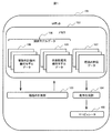
- FIG. 1 is a configuration example of a boxing robot (hereinafter referred to as a robot) 101 in the present embodiment.
- the robot 101 includes a memory 102, a boxing planning unit 103, a motion generation unit 104, and a manipulator 105.
- the memory 102 stores the robot 101, the storage container 201, the storage planned object 202, the boxed planned object 203 and the geometric model data 106 of the stored object 204, and the boxing plan data 107 generated by the boxing planning unit 103.
- the boxed planned object 203 is an object that has been stored in the storage container 201 in a simulation described later and has been boxed.
- the stored object 204 is an object that is already stored in the storage container 201.
- the geometric model data 106 includes boxing planning geometric model data 108 and state grasping geometric model data 109.
- the boxing planning unit 103 executes a simulation of moving the storage object 202 by the manipulator 105, and generates a boxing plan of the storage object 202 in the storage container 201.
- the boxing plan unit 103 stores the generated boxing plan in the memory 102 as boxing plan data 107.
- the action generation unit 104 generates an action of the manipulator 105 using the state grasping geometric model data 109 and the boxing plan data 107 stored in the memory 102 in order to execute the generated boxing plan by the manipulator 105.
- the manipulator 105 executes the operation generated by the operation generation unit 104.
- FIG. 2 is an example of a movement simulation of the storage object 202 based on the geometric model data 106.
- the geometric model data 106 of each object of the robot 101, the storage container 201, the storage planned object 202, the boxed planned object 203, and the stored object 204 includes position data, posture data, and shape data.
- the position data and the posture data respectively represent the position and posture of the representative point of each object.
- the representative point need not be one point.
- the shape data is stored as 3D point cloud data.
- the shape of the object may be approximated in advance to a primitive shape such as a rectangular parallelepiped or a cylinder, and stored as a combination of a primitive shape name and a parameter corresponding to the primitive shape such as the length of three sides of the rectangular parallelepiped. .
- a primitive shape such as a rectangular parallelepiped or a cylinder
- a parameter corresponding to the primitive shape such as the length of three sides of the rectangular parallelepiped.
- FIG. 3 is a processing flowchart of the boxing planning unit 103.
- the boxing planning unit 103 calculates a storage position candidate of the storage planned object 202 based on the geometric model data 106, and executes a simulation of moving the storage planned object 202 by the manipulator 105 toward one of the storage position candidates.
- the storage position candidate that has been moved is set as the storage position of the storage object 202.
- one storage target object 202 is selected in order from the plurality as a processing object, and the boxing planning unit 103 processes the selected processing object as a target. Execute.
- the order in which the processing objects are selected from the plurality of objects to be stored 202 is set in advance according to the descending order of the size of the objects.
- the boxing planning unit 103 initializes the boxing planning geometric model data 108 with the value of the state grasping geometric model data 109 (described later) (step 301).
- the values of the variables in the state grasping geometric model data 109 are used as the boxing planning geometric model data 108. Is assigned to the corresponding variable.
- the state grasping geometric model data 109 is converted into the data format of the boxing planning geometric model data 108. After conversion so as to match, it is substituted into the corresponding variable of the geometric model data 108 for boxing plan.
- the state grasping geometric model data 109 is data acquired by a sensing unit (not shown) except for the data of the boxed planned object 203.
- the data of the robot 101 is acquired from an encoder or the like mounted on the robot 101, and the data of the storage container 201, the storage scheduled object 202, and the stored object 204 are acquired from a camera or the like.
- the data of the boxed planned object 203 is acquired from the boxed plan data 107 stored in the memory 102.
- the data of the storage container 201, the storage scheduled object 202, and the stored object 204 may not be acquired by the sensing unit.
- the relative positions of the robot 101, the storage container 201, and the storage object 202 are fixed values
- the fixed values may be used as the position data of the storage container 201 and the storage object 202.
- the data of the stored object 204 may be acquired from the boxing plan data 107 stored in the memory 102.
- the boxing planning unit 103 acquires the boxing planning geometric model data 108 from the memory 102, and calculates storage position candidates (step 302).
- the boxing planning unit 103 uses the boxing planning geometric model data 108 acquired from the memory 102 to project an image projected on a plane parallel to the bottom surface of the storage container 201 (in a figure representing the bottom surface of the storage container 201 An image obtained by projecting the bottom graphics of the object 203 and the stored object 204 is generated.
- the boxing planning unit 103 performs corner detection processing on the generated image, and geometrically determines the corners of the area where the boxed planned object 203 and the stored object 204 are not present in the bottom surface of the storage container 201.
- the corner is a storage position candidate.
- the boxing planning unit 103 does not need to use the bottom image of the storage container 201 in order to obtain the corners of the area without the boxed planned object 203 and the stored object 204 in the storage container 201.
- the boxing planning unit 103 executes corner detection processing on the three-dimensional point cloud data, and the storage container 201, By combining with the position data and the posture data of the boxed planned object 203 and the stored object 204, the corner of the area without the boxed planned object 203 and the stored object 204 in the storage container 201 is obtained.
- the boxing planning unit 103 can obtain not only a two-dimensional corner viewed from a specific direction of the storage container 201 but also a three-dimensional corner by using the three-dimensional point cloud data. In addition, the boxing planning unit 103 may exclude the position determined to be unable to store the object by processing the previous object from the storage position candidates. The boxing plan unit 103 can speed up the generation of the boxing plan by narrowing down the storage position candidates using the processing result of the previous object.
- the boxing planning unit 103 executes a simulation for holding the processing object with the manipulator 105 (step 303).
- the manipulator 105 mounts a suction pad (not shown) on its hand (picking head) to hold an object.
- a vacuum control device not shown
- the holding operation of the manipulator 105 in the simulation by the boxing planning unit 103 means that the suction pad and the processing object move integrally. Further, the suction pad need not be used in order for the manipulator 105 to hold the object.
- the processing object may be gripped with a multi-finger gripper.
- the processing object When the processing object is actually held by the manipulator 105, the processing object can be gripped by the multi-finger gripper even when the processing object does not have a flat surface or when the processing object is heavy and cannot be sucked by the suction pad.
- the holding operation of the manipulator 105 in the simulation by the boxing planning unit 103 means that the multi-finger gripper and the processing object move together as in the case of using the suction pad.
- the boxing planning unit 103 selects one of the storage position candidates calculated in step 302 as a target storage position (step 304).
- the boxing planning unit 103 assigns different numbers to the respective storage position candidates, and selects a storage position candidate corresponding to the number selected using a random number as the target storage position.
- the boxing planning unit 103 does not have to randomly select the target storage position.
- the boxing planning unit 103 may prioritize the storage position candidates according to a predetermined rule and select the storage position candidate with the highest priority as the target storage position.
- the rules for assigning priorities increase the priority of storage position candidates that are in contact with the previously processed object, and decrease the priority of storage position candidates that are determined to be unable to be stored by processing the previous object.
- the priority is increased in the ascending order of points projected on all the storage position candidates on a certain axis (for example, the axis parallel to one side of the storage container 201), and the priority is increased in the ascending order of the similarity of the shape with the processing object.
- the target storage position selected by the boxing planning unit 103 may be plural. In that case, the boxing planning unit 103 executes the determination of whether or not the trajectory can be generated in step 305 for each target storage position.
- the boxing planning unit 103 determines whether or not the manipulator 105 can generate a trajectory that moves the processing object toward the target storage position (step 305). For trajectory generation, methods such as Rapidly-exploring Random Trees (RRT), Probabilistic Roadmap Method (PRM), and linear interpolation are used.
- RRT Rapidly-exploring Random Trees
- PRM Probabilistic Roadmap Method
- linear interpolation are used.
- obstacles such as the storage container 201, the boxed planned object 203, the stored object 204, and the storage target object 202 other than the processing object in the region through which the processing object and the robot 101 pass
- the boxing planning unit 103 determines that a trajectory can be generated, generates a trajectory, and executes Step 306. In other cases, the boxing planning unit 103 determines that the trajectory cannot be generated, and executes Step 308.
- the boxing planning unit 103 executes a simulation in which the manipulator 105 moves the processing object according to the trajectory generated in step 305 (step 306).
- the boxing planning unit 103 executes a simulation for releasing the holding of the processing object by the manipulator 105 (step 307), and executes step 310.
- the boxing planning unit 103 excludes the target storage position selected in step 304 from the storage position candidates (step 308), and determines whether storage position candidates remain (step 309). If the storage position candidates remain, the boxing planning unit 103 returns to step 304. If no storage position candidates remain, the boxing planning unit 103 determines that the processing object cannot be stored in the storage container 201 and executes step 310.
- the boxing plan unit 103 updates the boxing plan data 107 stored in the memory 102 (step 310).
- the boxing plan data 107 includes storage order data and storage geometric data of each boxed planned object 203.
- the storage order data is an order for selecting a processing object set in advance. If it is determined in step 309 that the processing object cannot be stored in the storage container 201, the boxing planning unit 103 thins out the corresponding processing object from the storage order data.
- the initial value of the storage geometric data is the geometric model data 109 for grasping the state of the storage planned object 202.
- the boxing planning unit 103 When simulating the movement of the processing object in Step 306, the boxing planning unit 103 overwrites the storage geometric data of the processing object with the position data and orientation data of the processing object of the movement destination, and the processing object is replaced with the boxed planned object 203. To do. Further, the boxing plan data 107 may include the trajectory (data) generated in step 305. By including the trajectory in the boxing plan data 107, it is not necessary to generate the trajectory again by the motion generation unit 104, and the motion generation can be speeded up.
- the operation generation unit 104 After the boxing plan unit 103 completes the generation of the boxing plan for the plurality of scheduled storage objects 202, the operation generation unit 104 generates an operation for executing the generated boxing plan by the manipulator 105. Based on the state grasping geometric model data 109 and the boxing plan data 107 stored in the memory 102, the manipulator 105 generates an operation for holding, moving, and storing the boxed planned objects 203 in order. When the boxing plan data 107 includes a trajectory for moving the boxed planned object 203, the motion generation unit 104 may generate a motion using the trajectory. In addition, every time one or a plurality of storage-scheduled objects 202 become boxed planned objects 203 in the boxing planning unit 103, the movement generation unit 104 may generate an operation of the manipulator 105.
- the corner of the stowable area is found using the intersection of the hand area of the manipulator 105 when moved within each limit angle range as the stowable area.
- the boxing planning unit 103 sets the hand of the manipulator 105 when the joint of the robot 101 is operated within the limit angle range without causing the hand of the manipulator 105 holding the storage object 202 to interfere with the obstacle.
- the corner of the storable area is found with the area of the intersection of the movable area and the empty area as the storable area.
- the configuration of the robot 101 of this embodiment is the same as that of the first embodiment.
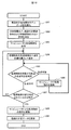
- FIG. 4 is a processing flowchart of the boxing planning unit 103.
- the boxing planning unit 103 determines the moving direction of the storage object 202, executes a simulation of moving the storage object 202 with the manipulator 105, obtains a distance variation (described later) between the boundary points of the storage area, and calculates the distance variation. Find the corner of the stowable area based on.
- one storage target object 202 is selected in order from the plurality as a processing object, and the boxing planning unit 103 displays a diagram for the selected processing object. 4 is executed.
- the order in which the processing objects are selected from the plurality of objects to be stored 202 is set in advance according to the descending order of the size of the objects. Further, the boxing planning unit 103 may combine the processes as appropriate, such as executing the process shown in the flowchart of FIG. 4 when it is determined in step 309 of FIG. 3 that the processing object cannot be stored in the storage container 201. .
- the boxing planning unit 103 executes the same process as step 301 in FIG. 3 (step 401).
- the boxing planning unit 103 acquires the boxing planning geometric model data 108 from the memory 102, and calculates an area in the storage container 201 where the boxed planning object 203 and the stored object 204 are not present (step 402).
- the boxing planning unit 103 executes the same process as step 303 in FIG. 3 (step 403).
- the boxing planning unit 103 determines an initial value of the moving direction of the processing object (step 404). Different numbers are assigned to the entire 360 degrees of the processing object for each unit angle (for example, 1 degree), and the boxing planning unit 103 sets the direction corresponding to the number selected using a random number as the initial value of the moving direction. And The boxing planning unit 103 does not have to randomly select an initial value in the movement direction. For example, when processing the second and subsequent objects of the storage-scheduled object 202, the boxing planning unit 103 will be described later in the direction toward the representative point of the previously processed object and the processing of the previous object.
- the moving direction when the distance fluctuation between the boundary points of the storable area becomes negative for the first time may be set as the initial value of the moving direction.
- the boxing planning unit 103 determines whether or not a trajectory for moving the processing object by the moving unit by the manipulator 105 in the moving direction can be generated (step 405).
- trajectory generation methods such as Rapidly-exploring Random Trees (RRT), Probabilistic Roadmap Method (PRM), and linear interpolation are used.
- the boxing planning unit 103 determines that a trajectory can be generated, generates a trajectory, and executes Step 406. In other cases, the boxing planning unit 103 determines that the trajectory cannot be generated, and executes Step 407.
- the boxing planning unit 103 executes a simulation of moving the processing object with the manipulator 105 according to the trajectory generated in step 405 (step 406), and returns to step 405.
- the boxing planning unit 103 stores the current position of the processing object as the boundary point position of the storable area (step 407).
- the boxing planning unit 103 determines the number of boundary points of the stored storage areas (step 408).
- the boxing planning unit 103 executes step 409 when the number of boundary points is 3 or more, and executes step 413 when the number of boundary points is 2 or less.
- the boxing planning unit 103 determines the distance variation between the boundary points of the storable area (step 409).
- the distance variation (d) between the boundary points of the storable area is expressed by the following equation. However, the boundary point of the storage area that is stored most recently is the point P A , the boundary point of the storage area that is stored one time before is the point P B , and the boundary point of the storage area that is stored two times before is the boundary point of the storage area the point P C.
- (Distance variation between boundary points of the housing area: d) (the point P A, the distance between the points P B) - (point P B, the point P C distance)
- Packing planning unit 103 the absolute value of the distance variation between boundary points of the housing area is smaller than a preset threshold, and, when the distance variation between boundary points of the housing area is negative, it can accommodate the point P A It is determined that it is the corner of the area, and step 410 is executed.
- the boxing planning unit 103 executes Step 412 when the absolute value of the distance fluctuation between the boundary points of the storable area is equal to or greater than a preset threshold value and the distance fluctuation between the boundary points of the storable area is negative. .
- the boxing planning unit 103 executes Step 413 when the distance variation between the boundary points of the storable area is 0 or more.
- the boxing planning unit 103 executes the same processing as step 307 in FIG. 3 (step 410).
- the boxing plan unit 103 updates the boxing plan data 107 stored in the memory 102 (step 411).
- the boxing plan data 107 includes storage order data and storage geometric data of each boxed planned object 203.
- the storage order data is an order for selecting a processing object set in advance.
- the initial value of the storage geometric data is the geometric model data 109 for grasping the state of the storage planned object 202.
- the housing geometry data processing object is overwritten with the position data and orientation data of the processing object at the point P A, the processing object and packing planned object 203.
- the boxing plan data 107 may include the trajectory (data) generated in step 405. By including the trajectory in the boxing plan data 107, the motion generation unit 104 can generate the movement trajectory of the object by using the trajectory included in the boxing plan data 107, so that the speed of motion generation can be increased.
- the boxing planning unit 103 uses the boundary point position data of the storable area to calculate the moving direction in which the processing object is closer to the corner of the storable area (step 412).
- FIG. 5 is a conceptual diagram showing the relationship between the boundary points of the storable area and the corner 502 of the storable area. As shown in FIG. 5, the distance fluctuation between the boundary points of the storable area is negative, that is, (the distance between the points P A and P B ) is smaller than the (the distance between the points P B and P C ) In some cases, the processing object 501 may be approaching the corner 502 of the retractable area.
- the boxing planning unit 103 calculates the moving direction of the processing object, which is different from both the moving direction that has been processed (steps 405 and 407 to 409 have been executed) and the reverse direction (step 413).
- the boxing planning unit 103 sets, as the movement direction, a direction in which the processed movement direction and the direction opposite to the processed movement direction are excluded from 360 degrees of the entire circumference of the processing object.
- the method of selecting the movement direction may be random as in step 404, or, for example, the reflection direction of the processed movement direction with respect to the boundary surface of the storage area may be set as a new movement direction.
- the boxing planning unit 103 returns to step 405 after calculating the moving direction.
- the corner of the storage area can be found and the object can be stored.
- the storage of the storage object 202 in the corner that allows the movement from a specific direction among the geometrically determined corners in the first embodiment will be described.
- the configuration of the robot 101 of this embodiment is the same as that of the first embodiment.
- FIG. 6 is a processing flowchart of the boxing planning unit 103.
- the boxing planning unit 103 selects one point around the processing object as a target position, executes a simulation of moving the storage target object 202 by the manipulator 105, and stores the boxed planned object 203 and the stored object 204 in the storage container 201.
- a position that is partially constrained by the boundary surface of the storable area with no storage is defined as the storage position of the storage object 202.
- one storage target object 202 is selected in order from the plurality as a processing object, and the boxing planning unit 103 displays a diagram for the selected processing object.
- the order in which the processing objects are selected from the plurality of objects to be stored 202 is set in advance according to the descending order of the size of the objects.
- the boxing planning unit 103 executes the same processing as Step 401 to Step 403 in FIG. 4 (Step 601 to Step 603).
- the boxing planning unit 103 selects one point around the processing object as a target position in the area calculated in step 602 (step 604).
- a peripheral area of a predetermined size is divided into a predetermined number of small blocks and a number is assigned to each block, and the boxing planning unit 103 selects a representative point of the block corresponding to the number selected using a random number.
- the position is the target position.
- the boxing planning unit 103 distributes a plurality of target position candidates in the area calculated in step 602 before the execution of step 604, and sets the target position candidate closest to the current position of the processing object as the target. It is good also as a position.
- the boxing planning unit 103 determines whether or not a trajectory for moving the object to be processed by the manipulator 105 toward the target position selected in Step 604 is determined (Step 605).
- trajectory generation methods such as Rapidly-exploring Random Trees (RRT), Probabilistic Roadmap Method (PRM), and linear interpolation are used.
- RRT Rapidly-exploring Random Trees
- PRM Probabilistic Roadmap Method
- linear interpolation linear interpolation
- the boxing planning unit 103 determines that a trajectory can be generated, generates a trajectory (data), and executes Step 606. In other cases, the boxing planning unit 103 determines that the trajectory cannot be generated, and executes Step 607.
- the boxing planning unit 103 executes a simulation of moving the processing object with the manipulator 105 according to the trajectory generated in step 605 (step 606), and returns to step 605.
- the boxing planning unit 103 is a boundary surface of the storage area in the storage container 201 where the boxed planning object 203 and the storage object 204 are not present (empty area). Is determined to be partially constrained (step 607).
- FIG. 7 shows an example of a state where the processing object is partially restricted.
- FIG. 7A shows a case where the shape of the processing object 501 is a rectangular parallelepiped (bottom surface is rectangular), and
- FIG. 7B shows a case where the shape of the processing object 501 is a cylinder (bottom surface is circular).
- FIG. 7A since the two surfaces (lines in the drawing) of the processing object 501 are in contact with the storage container 201 and the stored object 204, the movement in the direction of the arrow 703 is performed. It is restrained.
- FIG. 7B two lines 704 and 705 (two points in the drawing) of the processing object 501 are in contact with the storage container 201 and the stored object 204, and thus the arrow 706.
- Directional movement is constrained.
- the shape of the processing object 501 is a sphere, there are two contact points between the processing object 501 and the accommodable area.
- step 607 determines in step 607 that the processing object is partially constrained, it executes step 608. If the boxing planning unit 103 determines that the processing object is not partially constrained, the process returns to step 604.
- the boxing planning unit 103 executes the same process as step 307 in FIG. 3 (step 608).
- the boxing plan unit 103 updates the boxing plan data 107 stored in the memory 102 (step 609).
- the boxing plan data 107 includes storage order data and storage geometric data of each boxed planned object 203.
- the storage order data is an order for selecting a processing object set in advance.
- the initial value of the storage geometric data is the geometric model data 109 for grasping the state of the storage planned object 202.
- the storage geometric data of the processed object is overwritten with the position data and orientation data of the processed object being processed, and the processed object is set as the boxed planned object 203.
- the boxing plan data 107 may include the trajectory (data) generated in step 605. By including the trajectory in the boxing plan data 107, the motion generation unit 104 can generate the movement trajectory of the object by using the trajectory included in the boxing plan data 107, so that the speed of motion generation can be increased.
- the boxing planning unit 103 finds the boundary surface of the packable area in the area without the boxed planned object 203 and the stored object 204 in the storage container 201, the object is moved along the boundary surface.
- the configuration of the robot 101 of this embodiment is the same as that of the first embodiment.
- FIG. 8 is a processing flowchart of the boxing planning unit 103.
- the boxing planning unit 103 executes a simulation of moving the storage target object 202 by the manipulator 105, and moves the storage target object 202 along the boundary surface after the storage target object 202 contacts the boundary surface of the storage area. The position of the storage object 202 when it comes into contact with the boundary surface again is taken as the storage position.
- one storage target object 202 is selected in order from the plurality as a processing object, and the boxing planning unit 103 displays a diagram for the selected processing object.
- the order in which the processing objects are selected from the plurality of objects to be stored 202 is set in advance according to the descending order of the size of the objects.
- the boxing planning unit 103 executes the same processing as Step 401 to Step 404 in FIG. 4 (Step 801 to Step 804).
- the area that can be stored in the storage container 201 calculated in step 802 is defined as area A.
- the boxing planning unit 103 determines whether or not a trajectory for moving the processing object by the moving unit by the manipulator 105 in the moving direction can be generated (step 805).
- trajectory generation methods such as Rapidly-exploring Random Trees (RRT), Probabilistic Roadmap Method (PRM), and linear interpolation are used.
- the boxing planning unit 103 determines that a trajectory can be generated, generates a trajectory, and executes Step 806. In other cases, the boxing planning unit 103 determines that the trajectory cannot be generated, and executes Step 807.
- the boxing planning unit 103 executes a simulation of moving the processing object with the manipulator 105 according to the trajectory generated in step 805 (step 806), and returns to step 805.
- the boxing planning unit 103 determines the contact state between the processing object and the boundary surface of the storable area calculated in Step 802 (Step 807).
- FIG. 9 shows a contact state between the processing object 501 and the boundary surface of the storable area (area A) calculated in step 802 when the shape of the processing object 501 is a rectangular parallelepiped.
- 9A shows a state in which the processing object 501 is not in contact with the boundary surface of the area A calculated in step 802.
- FIG. 9B shows a state in which the processing object 501 faces the boundary surface of the area A calculated in step 802.
- FIG. 9C shows a state where the surface 902 and the surface 903 are in contact with each other on the boundary surface of the region A calculated in step 802.
- FIG. 9C is the same as FIG. 7A and shows a state in which the processing object 501 is partially restrained.
- the shape of the processing object 501 is not limited to a rectangular parallelepiped.
- the contact state can be defined similarly to the case where the shape of the processing object 501 is a rectangular parallelepiped.
- step 807 determines in step 807 that the processing object is not in contact with the boundary surface of the region A calculated in step 802
- the boxing planning unit 103 returns to step 804. If the boxing planning unit 103 determines that it is in contact with the boundary surface of the area A, it executes Step 808. If the boxing planning unit 103 determines that the boundary surface of the region A is in contact with the two surfaces, step 809 is executed.
- the boxing planning unit 103 uses the boxing planning geometric model data 108 to determine the moving direction along the boundary surface of the region A calculated in step 802 (step 808). After determining the moving direction, the boxing planning unit 103 returns to Step 805.
- the boxing planning unit 103 executes the same process as step 307 in FIG. 3 (step 809).
- the boxing plan unit 103 updates the boxing plan data 107 stored in the memory 102 (step 810).
- the boxing plan data 107 includes storage order data and storage geometric data of each boxed planned object 203.
- the storage order data is an order for selecting a processing object set in advance.
- the initial value of the storage geometric data is the geometric model data 109 for grasping the state of the storage planned object 202.
- the storage geometric data of the processed object is overwritten with the position data and orientation data of the processed object being processed, and the processed object is set as the boxed planned object 203.
- the boxing plan data 107 may include the trajectory (data) generated in step 805. By including the trajectory in the boxing plan data 107, the motion generation unit 104 can generate the movement trajectory of the object using the trajectory included in the boxing plan data 107, so that the speed of motion generation can be increased.
- the processing object can be efficiently moved based on the shape of the region A in which the boxed planned object 203 and the stored object 204 are not present in the storage container 201, so that the shape of the storable region is a convex polyhedron.
- the generation time of the boxing plan can be shortened.
- a boxing plan that does not depend on the storage order of the storage target objects 202 set in advance is generated by repeating the processing of the boxing planning unit 103 of any one of the first to fourth embodiments a plurality of times. The method will be described.
- the configuration of the robot 101 of this embodiment is the same as that of the first embodiment.
- the memory 102 stores the robot 101, the storage container 201, the storage planned object 202, the boxed planned object 203, the geometric model data 106 of the stored object 204, and the boxing plan data 107 generated by the boxing planning unit 103.
- a data structure equivalent to the boxing plan data 107 is stored in a list as boxing plan candidate data.
- FIG. 10 is a processing flowchart of the boxing planning unit 103.
- the boxing planning unit 103 sets a plurality of different orders for selecting the processing objects from the plurality.
- the boxing plan unit 103 repeatedly generates a boxing plan.
- the boxing plan unit 103 stores the generated boxing plans in the memory 102 as boxing plan candidate data, and selects the boxing plan candidate data with the highest volumetric efficiency as the boxing plan data 107.
- the boxing planning unit 103 repeats steps 1002 to 1006 until the number of repetitions N reaches the preset number of repetitions N MAX from the initial value 1 (step 1001).
- the boxing planning unit 103 determines the order of selecting the processing objects (step 1002).
- the order in which the processing objects are selected is the order of numbers selected by assigning different numbers to the plurality of objects to be stored 202 and using random numbers.
- the order of selecting the processing objects may not be determined randomly. For example, the order may be determined according to the descending order of the size of the objects.
- the process executed in step 1004 to be described later includes a step of selecting using a random number (such as step 304 in FIG. 3), since the randomness is obtained even if the order of selecting the process objects is the same, the process object is selected.
- the order does not have to be changed every time.
- the boxing planning unit 103 selects a processing object according to the order determined in step 1002 (step 1003).
- the boxing planning unit 103 executes one of the processes shown in the processing flowchart of the boxing planning unit 103 in FIGS. 3, 4, 6, and 8 (step 1004).
- the boxing planning unit 103 determines whether the processing object being processed is the last storage target object 202 in the order determined in step 1002 (step 1005). If the processing object being processed is the storage scheduled object 202 at the end of the order, the boxing planning unit 103 executes Step 1006. If the processing object being processed is not the storage-scheduled object 202 at the end of the order, the boxing planning unit 103 returns to Step 1003.
- the boxing plan unit 103 additionally stores the boxing plan data 107 stored in the memory 102 in the boxing plan candidate data in the memory 102 (step 1006).
- the boxing plan unit 103 acquires boxing plan candidate data, and calculates the volumetric efficiency of boxing in each candidate (step 1007).
- the boxing plan unit 103 stores the boxing plan candidate data having the highest volumetric efficiency of boxing in the memory 102 as the boxing plan data 107 (step 1008).
- a plurality of boxing plan candidate data having randomness can be obtained, and the boxing plan candidate data having the highest boxing capacity efficiency (storage efficiency in the storage container) can be selected. It becomes difficult to fall into a local solution, and a boxing plan with high volumetric efficiency of boxing can be generated.
- FIG. 11 is a configuration example of the robot 101 in this embodiment.
- the robot 101 includes a memory 102, a detection unit 1101, a boxing planning unit 103, and a manipulator 105.
- the memory 102 stores the geometric model data 106 of the robot 101, the storage container 201, the storage object 202 and the stored object 204, and the boxing plan data 107 generated by the boxing planning unit 103.
- the geometric model data 106 includes boxing planning geometric model data 108 and state grasping geometric model data 109.
- the geometric model data 106 is the same as in the first to fourth embodiments, but details of the shape data need not be acquired.
- the detection unit 1101 detects an external force applied to the robot 101.
- the boxing plan unit 103 uses the boxing plan geometric model data 108 stored in the memory 102 to generate a boxing plan for the storage container 201 of the storage target object 202.
- the boxing plan unit 103 stores the generated boxing plan in the memory 102 as boxing plan data 107.
- the boxing plan unit 103 generates an operation to be executed by the manipulator 105 along with the generation of the boxing plan.
- the manipulator 105 executes the operation generated by the boxing planning unit 103.
- FIG. 12 is a processing flowchart of the boxing planning unit 103.
- This processing flowchart is the same as the processing flowchart (FIG. 6) of the third embodiment except that the operation of the manipulator 105 is replaced with the actual operation from the simulation, and the data used for the contact determination is replaced with the sensor data from the boxing planning geometric model data 108. Yes.
- the present embodiment will be described with reference to FIG. 12 in which the flowchart (FIG. 6) of the third embodiment is replaced. However, the first embodiment (FIG. 3), the second embodiment (FIG. 4), and the fourth embodiment (FIG. 8). Each of the flowcharts can be similarly replaced.
- the boxing planning unit 103 executes the same processing as Step 601 and Step 602 in FIG. 6 (Step 1201 and Step 1202).
- the boxing planning unit 103 holds the processing object with the manipulator 105 (step 1203).
- the boxing planning unit 103 executes the same process as in step 604 (step 1203).
- the boxing planning unit 103 determines whether or not a trajectory for moving the processing object with the manipulator 105 toward the target position selected in Step 1204 can be generated (Step 1205).
- trajectory generation methods such as Rapidly-exploring Random Trees (RRT), Probabilistic Roadmap Method (PRM), and linear interpolation are used.
- the boxing planning unit 103 determines that a trajectory can be generated, generates a trajectory (data), and executes Step 1206. . In other cases, the boxing planning unit 103 determines that the trajectory cannot be generated, and executes Step 1207.
- the boxing planning unit 103 moves the processing object with the manipulator 105 according to the trajectory generated in step 1205, and returns to step 1205 (step 1206).
- the boxing planning unit 103 Based on the output result of the detection unit 1101 (external force applied to the robot 101), the boxing planning unit 103 sets the storage area of the storage container 201 in the storage container 201 in the area where the boxed planned object 203 and the stored object 204 are not present. It is determined whether or not the boundary surface is partially constrained (step 1207).
- the detection unit 1101 is a force sensor or a contact sensor mounted on the hand or wrist of the manipulator 105. When the sensor value is larger than a preset threshold value, the processing object held by the manipulator 105 is in contact with either the storage container 201 or the stored object 204, and the boxing planning unit 103 is as shown in FIG. It is determined that the processing object is partially constrained, and step 1208 is executed.
- the processing object held by the manipulator 105 is not in contact with either the storage container 201 or the stored object 204, and the boxing planning unit 103 determines that the processing object is partially constrained. If it is not determined, the process returns to step 1204.
- the boxing planning unit 103 releases the holding of the processing object by the manipulator 105 (step 1208).
- the boxing plan unit 103 updates the boxing plan data 107 stored in the memory 102 (step 1209).
- the boxing plan data 107 includes storage order data and storage geometric data of each boxed planned object 203.
- the storage order data is an order for selecting a processing object set in advance.
- the initial value of the storage geometric data is the geometric model data 109 for grasping the state of the storage planned object 202.
- the boxing planning unit 103 overwrites the storage geometric data of the processed object with the position data and orientation data of the processed object being processed, and sets the processed object as the stored object 204.
- a boxing plan can be generated even when detailed shape data of the storage-scheduled object 202 cannot be acquired.
Landscapes
- Manipulator (AREA)
Abstract
箱詰めロボットは、収納容器に収納予定物体を収納するマニピュレータ、収納容器および収納予定物体の幾何モデルデータを格納するメモリ、および、収納容器の幾何モデルデータを用いて、収納容器の空き領域を算出し、収納予定物体をマニピュレータに保持させて空き領域内で移動させ、収納予定物体の移動の結果に基づき、空き領域内でかつマニピュレータの可動範囲内にある収納可能領域の隅を発見し、発見した隅を収納予定物体の収納位置に決定し、決定した収納位置に基づいて箱詰め計画データを更新する。
Description
本発明は、箱詰めロボットおよび箱詰めロボットによる箱詰め計画方法に関する。
製造、物流などの産業分野において、ロボットが物体をピッキングし箱詰めする技術が活用されている。背景技術として例えば、特許文献1、特許文献2、非特許文献1がある。
特許文献1は、ピッキングヘッドに配置された吸着具で、搬入コンベア上に並べて搬入された包装物品を吸着し、鋸歯状戴置面と仕切り板とで仕切られた梱包箱に並べる包装物品ハンドリング装置を記載している。
特許文献2は、パレットの上に戴置された下箱内にガイド部材を入れ、板状物を下箱の外側の縁とガイド部材との間に挿入し、それ以降は、ガイド部材に支えられている最後尾の板状物に次の板状物を近接させ、ガイド部材を板状物の厚み分移動し、次の板状物をガイド部材と最後尾の板状物との間に挿入することを繰返して、複数の板状物を箱詰めするシステムを記載している。
非特許文献1は、コンテナ内を平面で区切った各収納空間の位置、貨物の重さ等に基づいた優先順位をつけ、その優先順位に従って各収納空間と貨物の組合せを最適化して、コンテナに貨物を詰める計画を生成する方法を記載している。
Zhu Shunzhi and Hong Wenxing, "An Improved Optimization Algorithm for the Container Loading Problem," 2009 World Congress on Software Engineering WCSE '09, vol.2, pp.46-49, 2009.
特許文献1や特許文献2は、箱に同一種類の物体を収納することを前提として、箱内の仕切り板や箱に入れるガイド部材など収納補助部材が用いられている。しかし、物流現場においては、異なる複数種類の商品を収納箱に詰める必要があり、収納補助部材を予め準備しておくことは困難である。
非特許文献1は、制約条件として物体の安定性などの積まれ方に着目し、箱詰めの容積効率を最大化する問題に帰着させることによって、異なる複数種類の商品の収納箱への詰め方が計画されている。しかし、ロボットで箱に物体を収納するために必要となる、ロボットのマニピュレータの移動範囲内の障害物との干渉は考慮されていない。
開示する箱詰めロボットは、収納容器に収納予定物体を収納するマニピュレータ、収納容器および収納予定物体の幾何モデルデータを格納するメモリ、および、収納容器の幾何モデルデータを用いて、収納容器の空き領域を算出し、収納予定物体をマニピュレータに保持させて空き領域内で移動させ、収納予定物体の移動の結果に基づき、空き領域内でかつマニピュレータの可動範囲内にある収納可能領域の隅を発見し、発見した隅を収納予定物体の収納位置に決定し、決定した収納位置に基づいて箱詰め計画データを更新する。
開示する箱詰めロボットは、マニピュレータの移動範囲内の障害物を回避した箱詰め計画を生成できる。
以下、図面を参照して実施の形態および実施例を説明する。なお、実施の形態および実施例を説明するための全図において、同一機能を有するものは同一符号を付け、その繰り返しの説明は省略する。
図1は、本実施例における箱詰めロボット(以下、ロボット)101の構成例である。以下の図1の説明に、後述する図2に付した符号を用いる。ロボット101は、メモリ102、箱詰め計画部103、動作生成部104、およびマニピュレータ105を備える。
メモリ102は、ロボット101、収納容器201、収納予定物体202、箱詰め計画済物体203および収納済物体204の幾何モデルデータ106、並びに、箱詰め計画部103で生成される箱詰め計画データ107を格納する。箱詰め計画済物体203は、後述するシミュレーションで収納容器201内に収納され、箱詰め計画の済んだ物体である。収納済物体204は、収納容器201内にすでに収納されている物体である。
幾何モデルデータ106は、箱詰め計画用幾何モデルデータ108および状態把握用幾何モデルデータ109を含む。箱詰め計画部103は、幾何モデルデータ106に基づいて、マニピュレータ105で収納予定物体202を移動するシミュレーションを実行し、収納予定物体202の収納容器201への箱詰め計画を生成する。また、箱詰め計画部103は、生成した箱詰め計画を箱詰め計画データ107としてメモリ102に格納する。動作生成部104は、生成された箱詰め計画をマニピュレータ105で実行するために、メモリ102に格納された状態把握用幾何モデルデータ109および箱詰め計画データ107を用いて、マニピュレータ105の動作を生成する。マニピュレータ105は動作生成部104で生成された動作を実行する。
図2は、幾何モデルデータ106に基づいた収納予定物体202の移動シミュレーションの一例である。ロボット101、収納容器201、収納予定物体202、箱詰め計画済物体203および収納済物体204の各対象物の幾何モデルデータ106は、位置データ、姿勢データ、形状データで構成される。位置データおよび姿勢データはそれぞれ、各対象物の代表点の位置および姿勢を表す。代表点は一点でなくともよい。形状データは三次元点群データとして記憶される。または、予め対象物の形状を直方体や円柱などのプリミティブ形状に近似しておき、プリミティブ形状の名称と直方体の三辺の長さなどプリミティブ形状に対応するパラメータとの組合せとして記憶されていてもよい。プリミティブ形状に近似することによって、箱詰め計画の生成を高速化できる。
図3は、箱詰め計画部103の処理フローチャートである。箱詰め計画部103は、幾何モデルデータ106に基づいて収納予定物体202の収納位置候補を算出し、収納位置候補の一つに向かって、マニピュレータ105で収納予定物体202を移動するシミュレーションを実行し、移動できた収納位置候補を収納予定物体202の収納位置とする。一つの収納容器201に収納する収納予定物体202が複数ある場合、複数の中から順番に一つの収納予定物体202を選んで処理物体とし、箱詰め計画部103は、選んだ処理物体を対象に処理を実行する。複数の収納予定物体202から処理物体を選ぶ順序は物体の大きさの降順などに従って予め設定しておく。
箱詰め計画部103は、箱詰め計画用幾何モデルデータ108を状態把握用幾何モデルデータ109(後述)の値で初期化する(ステップ301)。箱詰め計画用幾何モデルデータ108と状態把握用幾何モデルデータ109が同じデータ形式でメモリ102に格納されている場合には、状態把握用幾何モデルデータ109の変数の値を箱詰め計画用幾何モデルデータ108の該当変数に代入する。箱詰め計画用幾何モデルデータ108と状態把握用幾何モデルデータ109が異なるデータ形式でメモリ102に格納されている場合には、状態把握用幾何モデルデータ109を箱詰め計画用幾何モデルデータ108のデータ形式に合うように変換した後、箱詰め計画用幾何モデルデータ108の該当変数に代入する。
状態把握用幾何モデルデータ109は、箱詰め計画済物体203のデータを除いて、図示しないセンシング部で取得するデータである。例えば、ロボット101のデータはロボット101に搭載されたエンコーダなどから取得し、収納容器201、収納予定物体202、および収納済物体204のデータはカメラなどから取得する。一方、箱詰め計画済物体203のデータは、メモリ102に格納された箱詰め計画データ107から取得する。また、収納容器201、収納予定物体202、収納済物体204のデータはセンシング部で取得しなくともよい。例えば、ロボット101と収納容器201、収納予定物体202との相対位置が固定値であれば、その固定値を収納容器201、収納予定物体202の位置データとしてもよい。また、収納予定物体202の二つ目以降の物体を処理する場合、収納済物体204のデータはメモリ102に格納された箱詰め計画データ107から取得してもよい。ロボット101と収納容器201、収納予定物体202との相対位置の値や箱詰め計画データ107を用いることによって、センシング部で取得したデータの処理が不要となり、箱詰め計画の生成を高速化できる。
箱詰め計画部103は、メモリ102から箱詰め計画用幾何モデルデータ108を取得し、収納位置候補を算出する(ステップ302)。箱詰め計画部103は、メモリ102から取得した箱詰め計画用幾何モデルデータ108を用いて、収納容器201の底面に並行な面に投影した画像(収納容器201の底面を表す図形内に、箱詰め計画済物体203および収納済物体204の底面図形を投影した画像)を生成する。箱詰め計画部103は、生成した画像に対してコーナー検出処理を実行し、収納容器201の底面内で箱詰め計画済物体203および収納済物体204のない領域の隅を幾何学的に求め、求めた隅を収納位置候補とする。箱詰め計画部103は、収納容器201内で箱詰め計画済物体203および収納済物体204のない領域の隅を求めるためには、収納容器201の底面画像を用いなくともよい。例えば、箱詰め計画用幾何モデルデータ108の形状データが三次元点群データとして記憶されている場合、箱詰め計画部103は、三次元点群データに対してコーナー検出処理を実行し、収納容器201、箱詰め計画済物体203および収納済物体204の位置データおよび姿勢データと組み合わせることによって、収納容器201内で箱詰め計画済物体203および収納済物体204のない領域の隅を求める。箱詰め計画部103は、三次元点群データを利用することによって、収納容器201の特定方向から見た二次元的な隅のみならず、三次元的な隅を求めることができる。また、箱詰め計画部103は、一つ前の物体の処理で物体を収納できないと判定した位置は収納位置候補から外してもよい。箱詰め計画部103は、一つ前の物体の処理結果を利用して収納位置候補を絞り込むことによって、箱詰め計画の生成を高速化できる。
箱詰め計画部103は、マニピュレータ105で処理物体を保持するシミュレーションを実行する(ステップ303)。マニピュレータ105は、その手先(ピッキングヘッド)に、図示しない吸着パッドを搭載し、物体を保持する。実際にマニピュレータ105で処理物体を保持するときには、図示しない真空制御装置を吸着パッドに接続して吸着パッドの空圧を制御することによって、処理物体の平面を吸着する。箱詰め計画部103によるシミュレーションにおけるマニピュレータ105の保持動作は、吸着パッドと処理物体が一体化して動くようになることを意味する。また、マニピュレータ105が物体を保持するために、吸着パッドを用いなくともよい。例えば、多指グリッパで処理物体を把持してもよい。実際にマニピュレータ105で処理物体を保持するときには、処理物体に平面がない場合や、処理物体の重量が大きく吸着パッドで吸着できない場合でも、多指グリッパで処理物体を把持できる。箱詰め計画部103によるシミュレーションにおけるマニピュレータ105の保持動作は、吸着パッドを用いた場合と同様、多指グリッパと処理物体が一体化して動くようになることを意味する。
箱詰め計画部103は、ステップ302で算出した収納位置候補のうちの一つを目標収納位置として選定する(ステップ304)。箱詰め計画部103は、各収納位置候補に互いに異なる番号を割り振っておき、乱数を用いて選んだ番号に該当する収納位置候補を目標収納位置として選ぶ。箱詰め計画部103は、目標収納位置をランダムに選ばなくともよい。例えば、箱詰め計画部103は、予め定めた規則に従って収納位置候補に優先順位を付けておき、最も優先度の高い収納位置候補を目標収納位置として選んでもよい。優先順位を付ける規則は、一つ前に処理した物体に接する収納位置候補の優先度を高くする、一つ前の物体の処理で物体を収納できないと判定した収納位置候補の優先度を低くする、全収納位置候補をある一軸(例えば、収納容器201の一辺に並行な軸)に投影した点の昇順で優先度を高くする、処理物体との形状の類似度の昇順で優先度を高くするなどである。また、箱詰め計画部103が選定する目標収納位置は複数でもよい。その場合、箱詰め計画部103は、ステップ305の軌道の生成可否の判定を各目標収納位置に対して実行する。
箱詰め計画部103は、マニピュレータ105で目標収納位置に向かって処理物体を移動する軌道の生成可否を判定する(ステップ305)。軌道生成には、Rapidly-exploring Random Trees(RRT)、Probabilistic Roadmap Method(PRM)、直線補間などの手法を用いる。マニピュレータ105で軌道どおりに処理物体を移動させるとき、処理物体やロボット101が通る領域内に収納容器201、箱詰め計画済物体203、収納済物体204、および処理物体以外の収納予定物体202などの障害物がなく、ロボット101の各関節角度が各々の制限角度範囲に収まると推定される場合、箱詰め計画部103は軌道生成可能と判定し、軌道を生成してステップ306を実行する。そのほかの場合、箱詰め計画部103は軌道生成不可と判定し、ステップ308を実行する。
箱詰め計画部103は、ステップ305で生成した軌道どおりにマニピュレータ105で処理物体を移動するシミュレーションを実行する(ステップ306)。
箱詰め計画部103は、マニピュレータ105による処理物体の保持を解除するシミュレーションを実行し(ステップ307)、ステップ310を実行する。
箱詰め計画部103は、ステップ304で選定した目標収納位置を収納位置候補から除外し(ステップ308)、収納位置候補が残っているか判定する(ステップ309)。収納位置候補が残っている場合には、箱詰め計画部103はステップ304に戻る。収納位置候補が残っていない場合には、箱詰め計画部103は、処理物体を収納容器201に収納できないと判定し、ステップ310を実行する。
箱詰め計画部103は、メモリ102に格納された箱詰め計画データ107を更新する(ステップ310)。箱詰め計画データ107は、収納順序データおよび各箱詰め計画済物体203の収納幾何データを含む。収納順序データは、予め設定しておいた処理物体を選ぶ順序である。箱詰め計画部103は、ステップ309で処理物体を収納容器201に収納できないと判定した場合、収納順序データから該当の処理物体を間引く。収納幾何データの初期値は、収納予定物体202の状態把握用幾何モデルデータ109である。箱詰め計画部103は、ステップ306で処理物体の移動をシミュレーションした場合、処理物体の収納幾何データを、移動先の処理物体の位置データおよび姿勢データで上書きし、処理物体を箱詰め計画済物体203とする。また、箱詰め計画データ107は、ステップ305で生成した軌道(データ)を含んでもよい。箱詰め計画データ107に軌道を含むことによって、動作生成部104で再度軌道を生成する必要がなくなり、動作生成を高速化できる。
箱詰め計画部103が、予定された複数の収納予定物体202の箱詰め計画の生成を完了した後、動作生成部104は、生成された箱詰め計画をマニピュレータ105で実行するための動作を生成する。メモリ102に格納された状態把握用幾何モデルデータ109と箱詰め計画データ107に基づいて、マニピュレータ105で各箱詰め計画済物体203を順番に保持、移動し、収納する動作を生成する。箱詰め計画データ107が、箱詰め計画済物体203を移動する軌道を含む場合、動作生成部104はその軌道を利用して動作を生成してもよい。また、箱詰め計画部103において一つまたは複数の収納予定物体202が箱詰め計画済物体203となる度に、動作生成部104でマニピュレータ105の動作を生成してもよい。
本実施例では、実施例1で幾何学的に求まる隅に向かって収納予定物体202を移動する軌道を生成できなかった場合の対応を説明する。本実施例は、収納容器201内で箱詰め計画済物体203および収納済物体204のない領域(空き領域)と、ロボット101の各関節を、ロボット101や収納容器201、箱詰め計画済物体203などの障害物と干渉しないように、各々の制限角度範囲内で動かしたときのマニピュレータ105の手先領域との積集合を収納可能領域として、収納可能領域の隅を発見する。換言すると、箱詰め計画部103は、収納予定物体202を保持するマニピュレータ105の手先を障害物と干渉させずに、ロボット101の関節を制限角度範囲内で動作させたときの、マニピュレータ105の手先の可動範囲である可動領域と空き領域との積集合の領域を収納可能領域として、収納可能領域の隅を発見する。本実施例のロボット101の構成は、実施例1と同様とする。
図4は、箱詰め計画部103の処理フローチャートである。箱詰め計画部103は、収納予定物体202の移動方向を決定し、マニピュレータ105で収納予定物体202を移動するシミュレーションを実行して収納可能領域の境界点間の距離変動(後述)を求め、距離変動に基づいて収納可能領域の隅を発見する。一つの収納容器201に収納する収納予定物体202が複数ある場合、複数の中から順番に一つの収納予定物体202を選んで処理物体とし、箱詰め計画部103は、選んだ処理物体に対して図4のフローチャートで示された処理を実行する。複数の収納予定物体202から処理物体を選ぶ順序は物体の大きさの降順などに従って予め設定しておく。また、箱詰め計画部103は、図3のステップ309で処理物体を収納容器201に収納できないと判定した場合に、図4のフローチャートで示された処理を実行するなど、適宜処理を組み合わせてもよい。
箱詰め計画部103は、図3のステップ301と同様の処理を実行する(ステップ401)。箱詰め計画部103は、メモリ102から箱詰め計画用幾何モデルデータ108を取得し、収納容器201内で箱詰め計画済物体203および収納済物体204のない領域を算出する(ステップ402)。箱詰め計画部103は、図3のステップ303と同様の処理を実行する(ステップ403)。
箱詰め計画部103は、処理物体の移動方向の初期値を決定する(ステップ404)。処理物体の全周360度に対して単位角度(例えば1度)ごとに互いに異なる番号を割り振っておき、箱詰め計画部103は、乱数を用いて選んだ番号に該当する方向を移動方向の初期値とする。箱詰め計画部103は、移動方向の初期値をランダムに選ばなくともよい。例えば、箱詰め計画部103は、収納予定物体202の二つ目以降の物体を処理する場合、一つ前に処理した物体の代表点へ向かう方向や、一つ前の物体の処理において、後述する収納可能領域の境界点間の距離変動が初めて負となったときの移動方向を移動方向の初期値としてもよい。
箱詰め計画部103は、移動方向へ向かってマニピュレータ105で処理物体を移動単位分移動する軌道の生成可否を判定する(ステップ405)。軌道生成には、Rapidly-exploring Random Trees(RRT)、Probabilistic Roadmap Method(PRM)、直線補間などの手法を用いる。マニピュレータ105で軌道どおりに処理物体を移動させるとき、処理物体やロボット101が通る領域内に収納容器201、箱詰め計画済物体203、収納済物体204、および処理物体以外の収納予定物体202などの障害物がなく、ロボット101の各関節角度が各々の制限角度範囲に収まると推定される場合、箱詰め計画部103は軌道生成可能と判定し、軌道を生成してステップ406を実行する。そのほかの場合、箱詰め計画部103は軌道生成不可と判定し、ステップ407を実行する。
箱詰め計画部103は、ステップ405で生成した軌道どおりにマニピュレータ105で処理物体を移動するシミュレーションを実行し(ステップ406)、ステップ405に戻る。
箱詰め計画部103は、処理物体の現在位置を収納可能領域の境界点位置として記憶する(ステップ407)。箱詰め計画部103は、記憶された収納可能領域の境界点の数を判定する(ステップ408)。箱詰め計画部103は、境界点の数が3以上の場合、ステップ409を実行し、境界点の数が2以下の場合、ステップ413を実行する。
箱詰め計画部103は、収納可能領域の境界点間の距離変動を判定する(ステップ409)。収納可能領域の境界点間の距離変動(d)は以下の式で表される。ただし、最も新しく記憶された収納可能領域の境界点を点PA、一回前に記憶された収納可能領域の境界点を点PB、二回前に記憶された収納可能領域の境界点を点PCとする。
(収納可能領域の境界点間の距離変動:d)=(点PA、点PB間距離)-(点PB、点PC間距離)
箱詰め計画部103は、収納可能領域の境界点間の距離変動の絶対値が予め設定した閾値より小さく、かつ、収納可能領域の境界点間の距離変動が負の場合、点PAを収納可能領域の隅であると判定し、ステップ410を実行する。箱詰め計画部103は、収納可能領域の境界点間の距離変動の絶対値が予め設定した閾値以上であり、かつ、収納可能領域の境界点間の距離変動が負の場合、ステップ412を実行する。箱詰め計画部103は、収納可能領域の境界点間の距離変動が0以上の場合、ステップ413を実行する。
(収納可能領域の境界点間の距離変動:d)=(点PA、点PB間距離)-(点PB、点PC間距離)
箱詰め計画部103は、収納可能領域の境界点間の距離変動の絶対値が予め設定した閾値より小さく、かつ、収納可能領域の境界点間の距離変動が負の場合、点PAを収納可能領域の隅であると判定し、ステップ410を実行する。箱詰め計画部103は、収納可能領域の境界点間の距離変動の絶対値が予め設定した閾値以上であり、かつ、収納可能領域の境界点間の距離変動が負の場合、ステップ412を実行する。箱詰め計画部103は、収納可能領域の境界点間の距離変動が0以上の場合、ステップ413を実行する。
箱詰め計画部103は、図3のステップ307と同様の処理を実行する(ステップ410)。
箱詰め計画部103は、メモリ102に格納された箱詰め計画データ107を更新する(ステップ411)。箱詰め計画データ107は、収納順序データおよび各箱詰め計画済物体203の収納幾何データを含む。収納順序データは、予め設定しておいた処理物体を選ぶ順序である。収納幾何データの初期値は収納予定物体202の状態把握用幾何モデルデータ109である。処理物体の収納幾何データを点PAにおける処理物体の位置データおよび姿勢データで上書きし、処理物体を箱詰め計画済物体203とする。また、箱詰め計画データ107は、ステップ405で生成した軌道(データ)を含んでもよい。箱詰め計画データ107に軌道を含むことによって、動作生成部104は、箱詰め計画データ107に含まれた軌道を利用して物体の移動軌道を生成できるので、動作生成を高速化できる。
箱詰め計画部103は、収納可能領域の境界点位置データを用いて、処理物体が収納可能領域の隅へより近づく移動方向を算出する(ステップ412)。
図5は、収納可能領域の境界点と収納可能領域の隅502との関係を表す概念図である。図5のように、収納可能領域の境界点間の距離変動が負、すなわち(点PB、点PC間距離)に比べて(点PA、点PB間距離)が減少しているとき、処理物体501は収納可能領域の隅502へ近づいている場合がある。そのため、点PCを始点、点PAを終点とするベクトル503を点PAが始点となるように平行移動したベクトル、またはその正規化ベクトル504と、点PAを始点、点PBを終点とするベクトル、またはその正規化ベクトル505との合成ベクトル506を移動方向として、処理物体501を収納可能領域の隅502へ近づける。箱詰め計画部103は、移動方向を算出した後、ステップ405に戻る。
箱詰め計画部103は、処理済(ステップ405、ステップ407~ステップ409を実行済み)の移動方向および逆方向のいずれとも異なる、処理物体の移動方向を算出する(ステップ413)。箱詰め計画部103は、処理物体の全周360度のうち、処理済の移動方向および処理済の移動方向と逆向きの方向を除外した方向を移動方向とする。移動方向の選び方は、ステップ404と同様に、ランダムでもよいし、例えば、収納可能領域の境界面に対して処理済の移動方向の反射方向を新たな移動方向としてもよい。箱詰め計画部103は、移動方向を算出した後、ステップ405に戻る。
本実施例によって、幾何学的に求まる隅に向かって物体を移動する軌道を生成できなかった場合でも、収納可能領域の隅を発見し、物体を収納することができる。
本実施例では、実施例1で幾何学的に求まる隅のうち、特定方向からの移動を許す隅への収納予定物体202の収納を説明する。本実施例のロボット101の構成、は実施例1と同様とする。
図6は、箱詰め計画部103の処理フローチャートである。箱詰め計画部103は、処理物体の周辺領域の一点を目標位置として選定し、マニピュレータ105で収納予定物体202を移動するシミュレーションを実行し、収納容器201内で箱詰め計画済物体203および収納済物体204のない、収納可能領域の境界面に部分拘束されている位置を収納予定物体202の収納位置とする。一つの収納容器201に収納する収納予定物体202が複数ある場合、複数の中から順番に一つの収納予定物体202を選んで処理物体とし、箱詰め計画部103は、選んだ処理物体に対して図6のフローチャートで示された処理を実行する。複数の収納予定物体202から処理物体を選ぶ順序は物体の大きさの降順などに従って予め設定しておく。
箱詰め計画部103は、図4のステップ401~ステップ403と同様の処理を実行する(ステップ601~ステップ603)。
箱詰め計画部103は、ステップ602で算出した領域内で、処理物体の周辺領域の一点を目標位置として選定する(ステップ604)。予め定めた大きさの周辺領域内を予め定めた数の小ブロックに区切って各ブロックに番号を割り振っておき、箱詰め計画部103は、乱数を用いて選んだ番号に該当するブロックの代表点の位置を目標位置とする。また、箱詰め計画部103は、ステップ604の実行より前の段階で、ステップ602で算出した領域内に複数の目標位置候補を分布させておき、処理物体の現在位置から最も近い目標位置候補を目標位置としてもよい。
箱詰め計画部103は、ステップ604で選定した目標位置へ向かってマニピュレータ105で処理物体を移動する軌道の生成可否を判定する(ステップ605)。軌道生成には、Rapidly-exploring Random Trees(RRT)、Probabilistic Roadmap Method(PRM)、直線補間などの手法を用いる。マニピュレータ105で軌道どおりに処理物体を移動させるとき、処理物体やロボット101が通る領域内に収納容器201、箱詰め計画済物体203、収納済物体204、および処理物体以外の収納予定物体202などの障害物がなく、ロボット101の各関節角度が各々の制限角度範囲に収まると推定される場合、箱詰め計画部103は軌道生成可能と判定し、軌道(データ)を生成してステップ606を実行する。そのほかの場合、箱詰め計画部103は軌道生成不可と判定し、ステップ607を実行する。
箱詰め計画部103は、ステップ605で生成した軌道どおりにマニピュレータ105で処理物体を移動するシミュレーションを実行し(ステップ606)、ステップ605に戻る。
箱詰め計画部103は、箱詰め計画用幾何モデルデータ108に基づいて、処理物体が収納容器201内で箱詰め計画済物体203および収納済物体204のない領域(空き領域)内の収納可能領域の境界面に部分拘束されているか判定する(ステップ607)。
図7は、処理物体が部分拘束されている状態の一例である。図7(a)は処理物体501の形状が直方体(底面が矩形)の場合、図7(b)は処理物体501の形状が円柱(底面が円形)の場合である。図7(a)では、処理物体501の面701および面702の二面(図中では線)が、収納容器201および収納済物体204の各々と接触しているため、矢印703方向の移動が拘束されている。図7(b)では、処理物体501のうち線704および線705の二本の線(図中では二点)が、収納容器201および収納済物体204の各々と接触しているため、矢印706方向の移動が拘束されている。処理物体501の形状が球形の場合、処理物体501と収納可能領域の境界面接触は2点になる。
箱詰め計画部103は、ステップ607で、処理物体が部分拘束されていると判定した場合、ステップ608を実行する。箱詰め計画部103は、処理物体が部分拘束されていないと判定した場合、ステップ604へ戻る。
箱詰め計画部103は、図3のステップ307と同様の処理を実行する(ステップ608)。
箱詰め計画部103は、メモリ102に格納された箱詰め計画データ107を更新する(ステップ609)。箱詰め計画データ107は、収納順序データおよび各箱詰め計画済物体203の収納幾何データを含む。収納順序データは、予め設定しておいた処理物体を選ぶ順序である。収納幾何データの初期値は収納予定物体202の状態把握用幾何モデルデータ109である。処理物体の収納幾何データを、処理中の処理物体の位置データおよび姿勢データで上書きし、処理物体を箱詰め計画済物体203とする。また、箱詰め計画データ107は、ステップ605で生成した軌道(データ)を含んでもよい。箱詰め計画データ107に軌道を含むことによって、動作生成部104は、箱詰め計画データ107に含まれた軌道を利用して物体の移動軌道を生成できるので、動作生成を高速化できる。
本実施例によって、幾何学的に求まる隅のうち、特定方向からの移動を許す隅への物体の収納も可能となるため、箱詰めの容積効率を上げることができる。
本実施例では、箱詰め計画部103が収納容器201内で箱詰め計画済物体203および収納済物体204のない領域内の収納可能領域の境界面を発見した後、境界面に沿って物体を移動させることによって、箱詰め計画の生成時間を短縮する方法を説明する。本実施例のロボット101の構成は実施例1と同様とする。
図8は、箱詰め計画部103の処理フローチャートである。箱詰め計画部103は、マニピュレータ105で収納予定物体202を移動させるシミュレーションを実行し、収納可能領域の境界面に収納予定物体202が接触した後、境界面に沿うように収納予定物体202を移動させ、再び境界面に接触したときの収納予定物体202の位置を収納位置とする。一つの収納容器201に収納する収納予定物体202が複数ある場合、複数の中から順番に一つの収納予定物体202を選んで処理物体とし、箱詰め計画部103は、選んだ処理物体に対して図8のフローチャートで示された処理を実行する。複数の収納予定物体202から処理物体を選ぶ順序は物体の大きさの降順などに従って予め設定しておく。
箱詰め計画部103は、図4のステップ401~ステップ404と同様の処理を実行する(ステップ801~ステップ804)。ただし、ステップ802で算出する、収納容器201内で収納可能領域を領域Aとする。
箱詰め計画部103は、移動方向に向かってマニピュレータ105で処理物体を移動単位分移動する軌道の生成可否を判定する(ステップ805)。軌道生成には、Rapidly-exploring Random Trees(RRT)、Probabilistic Roadmap Method(PRM)、直線補間などの手法を用いる。マニピュレータ105で軌道どおりに処理物体を移動するとき、処理物体やロボット101が通る領域内に収納容器201、箱詰め計画済物体203、収納済物体204、および処理物体以外の収納予定物体202などの障害物がなく、ロボット101の各関節角度が各々の制限角度範囲に収まると推定される場合、箱詰め計画部103は軌道生成可能と判定し、軌道を生成してステップ806を実行する。そのほかの場合、箱詰め計画部103は軌道生成不可と判定し、ステップ807を実行する。
箱詰め計画部103は、ステップ805で生成した軌道どおりにマニピュレータ105で処理物体を移動するシミュレーションを実行し(ステップ806)、ステップ805に戻る。
箱詰め計画部103は、処理物体とステップ802で算出した収納可能領域の境界面との接触状態を判定する(ステップ807)。
図9は、処理物体501の形状が直方体の場合における、処理物体501とステップ802で算出した収納可能領域(領域A)の境界面との接触状態である。図9(a)は処理物体501がステップ802で算出した領域Aの境界面に接触していない状態、図9(b)は、処理物体501がステップ802で算出した領域Aの境界面に面901で一面接触している状態、図9(c)は、処理物体501がステップ802で算出した領域Aの境界面に面902および面903で二面接触している状態である。図9(c)は、図7(a)と同様であり、処理物体501が部分拘束されている状態である。処理物体501の形状は直方体に限らない。例えば、処理物体501の形状が円柱の場合にも、処理物体501の形状が直方体の場合と同様に接触状態を定義できる。
箱詰め計画部103は、ステップ807で、処理物体がステップ802で算出した領域Aの境界面に接触していないと判定した場合、ステップ804に戻る。箱詰め計画部103は、領域Aの境界面に一面で接触していると判定した場合、ステップ808を実行する。箱詰め計画部103は、領域Aの境界面に二面で接触していると判定した場合、ステップ809を実行する。
箱詰め計画部103は、箱詰め計画用幾何モデルデータ108を用いて、ステップ802で算出した領域Aの境界面に沿う移動方向を決定する(ステップ808)。箱詰め計画部103は、移動方向を決定した後、ステップ805に戻る。
箱詰め計画部103は、図3のステップ307と同様の処理を実行する(ステップ809)。
箱詰め計画部103は、メモリ102に格納された箱詰め計画データ107を更新する(ステップ810)。箱詰め計画データ107は、収納順序データおよび各箱詰め計画済物体203の収納幾何データを含む。収納順序データは、予め設定しておいた処理物体を選ぶ順序である。収納幾何データの初期値は収納予定物体202の状態把握用幾何モデルデータ109である。処理物体の収納幾何データを、処理中の処理物体の位置データおよび姿勢データで上書きし、処理物体を箱詰め計画済物体203とする。また、箱詰め計画データ107は、ステップ805で生成した軌道(データ)を含んでもよい。箱詰め計画データ107に軌道を含むことによって、動作生成部104は、箱詰め計画データ107に含まれる軌道を利用して物体の移動軌道を生成できるので、動作生成を高速化できる。
本実施例によって、収納容器201内で箱詰め計画済物体203および収納済物体204のない領域Aの形状に基づいて、効率よく処理物体を移動させることができるので、収納可能領域の形状が凸多面体の場合の箱詰め計画の生成時間を短縮できる。
本実施例では、実施例1~実施例4のいずれかの箱詰め計画部103の処理を複数回繰返すことによって、予め設定しておいた収納予定物体202の収納順序に依存しない箱詰め計画を生成する方法を説明する。
本実施例のロボット101の構成は実施例1と同様の構成とする。ただし、メモリ102には、ロボット101、収納容器201、収納予定物体202、箱詰め計画済物体203、収納済物体204の幾何モデルデータ106、および、箱詰め計画部103で生成される箱詰め計画データ107のほかに、箱詰め計画候補データとして、箱詰め計画データ107と同等のデータ構造がリスト化されて格納されている。
図10は、箱詰め計画部103の処理フローチャートである。実施例1~実施例4では、一つの収納容器201に収納する収納予定物体202が複数ある場合、複数の中から順番に一つの物体を選んで処理物体とし、処理物体に対して各々、図3、図4、図6、または図8の箱詰め計画部103の処理フローチャートで示された処理を実行した。本実施例では、箱詰め計画部103は、一つの収納容器201に収納する収納予定物体202が複数ある場合、複数の中から処理物体を選ぶ順序を異なる複数通りにする。異なる順序の各々に応じて、箱詰め計画部103は箱詰め計画を繰り返し生成する。箱詰め計画部103は、生成した各箱詰め計画を箱詰め計画候補データとしてメモリ102に格納し、最も容積効率の高い箱詰め計画候補データを箱詰め計画データ107として選択する。
箱詰め計画部103は、繰返し回数Nが初期値1からあらかじめ設定した繰返し上限回数NMAXに到達するまで、ステップ1002~ステップ1006を繰返す(ステップ1001)。
箱詰め計画部103は、処理物体を選ぶ順序を決定する(ステップ1002)。処理物体を選ぶ順序は、複数の収納予定物体202に互いに異なる番号を割り振っておき、乱数を用いて選んだ番号順とする。処理物体を選ぶ順序はランダムに決定しなくともよい。例えば、物体の大きさの降順などに従って順序を決定してもよい。また、後述するステップ1004で実行される処理に乱数を用いて選ぶステップ(図3のステップ304など)が含まれる場合、処理物体を選ぶ順序が同じでもランダム性が得られるため、処理物体を選ぶ順序を毎回変えなくともよい。
箱詰め計画部103は、ステップ1002で決定した順序に従って処理物体を選択する(ステップ1003)。
箱詰め計画部103は、図3、図4、図6、および図8の箱詰め計画部103の処理フローチャートで示された処理のいずれかを実行する(ステップ1004)。
箱詰め計画部103は、処理中の処理物体が、ステップ1002で決定した順序の末尾の収納予定物体202かを判定する(ステップ1005)。処理中の処理物体が順序の末尾の収納予定物体202である場合、箱詰め計画部103はステップ1006を実行する。処理中の処理物体が順序の末尾の収納予定物体202でない場合、箱詰め計画部103はステップ1003に戻る。
箱詰め計画部103は、メモリ102に格納された箱詰め計画データ107を、メモリ102の箱詰め計画候補データに追加で格納する(ステップ1006)。
箱詰め計画部103は、箱詰め計画候補データを取得し、各候補における箱詰めの容積効率を算出する(ステップ1007)。箱詰め計画部103は、箱詰めの容積効率の最も高い箱詰め計画候補データを箱詰め計画データ107としてメモリ102に格納する(ステップ1008)。
本実施例によって、ランダム性を持たせた複数の箱詰め計画候補データを得て、箱詰めの容積効率(収納容器への収納効率)の最も高い箱詰め計画候補データを選ぶことができるので、箱詰め計画が局所解に陥りにくくなり、箱詰めの容積効率の高い箱詰め計画を生成できる。
本実施例では、実施例1~実施例4の、マニピュレータ105の動作のシミュレーションを実際のマニピュレータ105の動作とし、力センサなどを用いて物体間の接触判定を行う方法を説明する。
図11は、本実施例におけるロボット101の構成例である。ロボット101は、メモリ102、検知部1101、箱詰め計画部103、およびマニピュレータ105を備える。メモリ102は、ロボット101、収納容器201、収納予定物体202および収納済物体204の幾何モデルデータ106、並びに、箱詰め計画部103で生成される箱詰め計画データ107を格納する。幾何モデルデータ106は、箱詰め計画用幾何モデルデータ108および状態把握用幾何モデルデータ109を含む。幾何モデルデータ106は、実施例1~実施例4と同様であるが、形状データの詳細は取得しなくともよい。検知部1101は、ロボット101への外力を検知する。箱詰め計画部103は、メモリ102に格納された箱詰め計画用幾何モデルデータ108を用いて、収納予定物体202の収納容器201への箱詰め計画を生成する。また、箱詰め計画部103は、生成した箱詰め計画を箱詰め計画データ107としてメモリ102に格納する。箱詰め計画部103は、箱詰め計画の生成と共に、マニピュレータ105が実行する動作を生成する。マニピュレータ105は、箱詰め計画部103が生成した動作を実行する。
図12は、箱詰め計画部103の処理フローチャートである。本処理フローチャートは、実施例3の処理フローチャート(図6)において、マニピュレータ105の動作をシミュレーションから実際の動作に置き換え、接触の判定に用いるデータを箱詰め計画用幾何モデルデータ108からセンサデータに置き換えている。本実施例では、実施例3のフローチャート(図6)を置き換えた図12を参照して説明するが、実施例1(図3)、実施例2(図4)、実施例4(図8)の各フローチャートも同様に置き換えることができる。
箱詰め計画部103は、図6のステップ601、ステップ602と同様の処理を実行する(ステップ1201、ステップ1202)。
箱詰め計画部103は、マニピュレータ105で処理物体を保持する(ステップ1203)。
箱詰め計画部103は、ステップ604と同様の処理を実行する(ステップ1203)。
箱詰め計画部103は、ステップ1204で選定した目標位置へ向かってマニピュレータ105で処理物体を移動する軌道の生成可否を判定する(ステップ1205)。軌道生成には、Rapidly-exploring Random Trees(RRT)、Probabilistic Roadmap Method(PRM)、直線補間などの手法を用いる。マニピュレータ105で軌道どおりに処理物体を移動するとき、処理物体やロボット101が通る領域内に収納容器201、箱詰め計画済物体203、収納済物体204、および処理物体以外の収納予定物体202などの障害物がなく、ロボット101の各関節角度が各々の制限角度範囲に収まると推定される場合は、箱詰め計画部103は軌道生成可能と判定し、軌道(データ)を生成してステップ1206を実行する。そのほかの場合、箱詰め計画部103は軌道生成不可と判定し、ステップ1207を実行する。
箱詰め計画部103は、ステップ1205で生成した軌道どおりにマニピュレータ105で処理物体を移動し、ステップ1205に戻る(ステップ1206)。
箱詰め計画部103は、検知部1101の出力結果(ロボット101への外力)に基づいて、処理物体が収納容器201内で箱詰め計画済物体203および収納済物体204のない領域内の収納可能領域の境界面に部分拘束されているか判定する(ステップ1207)。検知部1101は、マニピュレータ105の手先または手首に搭載された力センサ、接触センサなどである。センサの値が予め設定した閾値より大きい場合、マニピュレータ105で保持した処理物体は、収納容器201および収納済物体204のいずれかに接触しており、箱詰め計画部103は、図7に示すように処理物体は部分拘束されたと判定し、ステップ1208を実行する。センサの値が予め設定した閾値より小さい場合、マニピュレータ105で保持した処理物体は、収納容器201および収納済物体204のいずれにも接触しておらず、箱詰め計画部103は、処理物体は部分拘束されていないと判定し、ステップ1204に戻る。
箱詰め計画部103は、マニピュレータ105による処理物体の保持を解除する(ステップ1208)。
箱詰め計画部103は、メモリ102に格納された箱詰め計画データ107を更新する(ステップ1209)。箱詰め計画データ107は、収納順序データおよび各箱詰め計画済物体203の収納幾何データを含む。収納順序データは、予め設定しておいた処理物体を選ぶ順序である。収納幾何データの初期値は収納予定物体202の状態把握用幾何モデルデータ109である。箱詰め計画部103は、処理物体の収納幾何データを処理中の処理物体の位置データおよび姿勢データで上書きし、処理物体を収納済物体204とする。
本実施例によって、力センサなどを用いて物体間の接触判定を行うため、収納予定物体202の詳細な形状データを取得できない場合でも箱詰め計画を生成できる。
101…ロボット、102…メモリ、103…箱詰め計画部、104…動作生成部、105…マニピュレータ、106…幾何モデルデータ、107…箱詰め計画データ、108…箱詰め計画用幾何モデルデータ、109…状態把握用幾何モデルデータ、201…収納容器、202…収納予定物体、203…箱詰め計画済物体、204…収納済物体、501…処理物体、502…収納可能領域の隅、503…点PCを始点、点PAを終点とするベクトル、504…ベクトル503を点PAが始点となるように並行移動したベクトルの正規化ベクトル、505…点PAを始点、点PBを終点とするベクトルの正規化ベクトル、506…合成ベクトル、701…接触面、702…接触面、703…拘束方向、704…接触点、705…接触点、706…拘束方向、901…接触面、902…接触面、903…接触面、1101…検知部。
Claims (10)
- 収納容器に収納予定物体を収納するマニピュレータ、
前記収納容器および前記収納予定物体の幾何モデルデータを格納するメモリ、および、
前記収納容器の前記幾何モデルデータを用いて、前記収納容器の空き領域を算出し、前記収納予定物体を前記マニピュレータに保持させて前記空き領域内で移動させ、前記収納予定物体の前記移動の結果に基づき、前記空き領域内でかつ前記マニピュレータの可動範囲内にある収納可能領域の隅を発見し、発見した前記隅を前記収納予定物体の収納位置に決定し、決定した前記収納位置に基づいて箱詰め計画データを更新する箱詰め計画部を有することを特徴とする箱詰めロボット。 - 前記収納予定物体の前記空き領域内での前記移動は、前記収納予定物体を保持する前記マニピュレータのシミュレーションによる移動であることを特徴とする請求項1記載の箱詰めロボット。
- 前記箱詰め計画部は、前記収納予定物体を保持する前記マニピュレータの手先を前記移動の障害物と干渉させずに、当該箱詰めロボットの関節を制限角度範囲内で動作させたときの、前記マニピュレータの手先の可動範囲である可動領域と前記空き領域との積集合の領域を前記収納可能領域として、前記収納可能領域の前記隅を発見することを特徴とする請求項2記載の箱詰めロボット。
- 前記箱詰め計画部は、前記空き領域内の前記収納予定物体の周辺領域の一点を目標位置として選定し、前記シミュレーションによる前記収納予定物体の前記移動の結果、前記収納可能の境界面と前記収納予定物体とが少なくとも2点で接触する部分拘束されている前記収納予定物体の位置を前記収納位置とすることを特徴とする請求項3記載の箱詰めロボット。
- 前記箱詰め計画部は、前記収納可能の前記境界面に沿って、前記シミュレーションにより前記収納予定物体の前記移動を実行することを特徴とする請求項4記載の箱詰めロボット。
- 前記箱詰め計画部は、前記収納容器に収納する前記収納予定物体が複数ある場合、複数の前記収納予定物体の選択順序を複数通り設け、複数通りの前記選択順序の各々に応じて、前記収納予定物体の前記収納位置の候補を決定し、決定した前記候補から収納効率の高い前記候補を前記収納位置として選択することを特徴とする請求項5記載の箱詰めロボット。
- 前記収納予定物体の前記空き領域内での前記移動は、前記収納予定物体を保持する前記マニピュレータによる移動であることを特徴とする請求項1記載の箱詰めロボット。
- 収納容器に収納予定物体を収納するマニピュレータ、および、前記収納容器および前記収納予定物体の幾何モデルデータを格納するメモリを有する箱詰めロボットによる箱詰め計画方法であって、前記箱詰めロボットは、
前記収納容器の前記幾何モデルデータを用いて、前記収納容器の空き領域を算出し、
前記収納予定物体を前記マニピュレータに保持させて前記空き領域内で移動させ、
前記収納予定物体の前記移動の結果に基づき、前記空き領域内でかつ前記マニピュレータの可動範囲内にある収納可能領域の隅を発見し、
発見した前記隅を前記収納予定物体の収納位置に決定し、
決定した前記収納位置に基づいて箱詰め計画データを更新することを特徴とする箱詰め計画方法。 - 前記収納予定物体の前記空き領域内での前記移動は、前記収納予定物体を保持する前記マニピュレータのシミュレーションによる移動であることを特徴とする請求項8記載の箱詰め計画方法。
- 前記箱詰めロボットは、前記収納予定物体を保持する前記マニピュレータの手先を前記移動の障害物と干渉させずに、当該箱詰めロボットの関節を制限角度範囲内で動作させたときの、前記マニピュレータの手先の可動範囲である可動領域と前記空き領域との積集合の領域を前記収納可能領域として、前記収納可能領域の前記隅を発見することを特徴とする請求項9記載の箱詰め計画方法。
Priority Applications (1)
| Application Number | Priority Date | Filing Date | Title |
|---|---|---|---|
| PCT/JP2016/056106 WO2017149616A1 (ja) | 2016-02-29 | 2016-02-29 | 箱詰めロボットおよび箱詰め計画方法 |
Applications Claiming Priority (1)
| Application Number | Priority Date | Filing Date | Title |
|---|---|---|---|
| PCT/JP2016/056106 WO2017149616A1 (ja) | 2016-02-29 | 2016-02-29 | 箱詰めロボットおよび箱詰め計画方法 |
Publications (1)
| Publication Number | Publication Date |
|---|---|
| WO2017149616A1 true WO2017149616A1 (ja) | 2017-09-08 |
Family
ID=59743659
Family Applications (1)
| Application Number | Title | Priority Date | Filing Date |
|---|---|---|---|
| PCT/JP2016/056106 WO2017149616A1 (ja) | 2016-02-29 | 2016-02-29 | 箱詰めロボットおよび箱詰め計画方法 |
Country Status (1)
| Country | Link |
|---|---|
| WO (1) | WO2017149616A1 (ja) |
Cited By (7)
| Publication number | Priority date | Publication date | Assignee | Title |
|---|---|---|---|---|
| CN107977756A (zh) * | 2017-12-21 | 2018-05-01 | 厦门大学嘉庚学院 | 解决三维装箱问题的三叉树规划计算方法 |
| CN109835706A (zh) * | 2017-11-24 | 2019-06-04 | 发那科株式会社 | 工件配置系统 |
| WO2019206924A1 (en) * | 2018-04-23 | 2019-10-31 | Franka Emika Gmbh | Method for inserting objects into a common object receptacle |
| CN110615227A (zh) * | 2019-09-10 | 2019-12-27 | 灵动科技(北京)有限公司 | 自动搬运系统 |
| CN110884715A (zh) * | 2018-09-07 | 2020-03-17 | 株式会社日立物流 | 机器人系统及其控制方法 |
| US11045946B2 (en) | 2018-03-19 | 2021-06-29 | Kabushiki Kaisha Toshiba | Holding device, transport system, and controller |
| DE112021002430T5 (de) | 2020-04-21 | 2023-02-16 | Fanuc Corporation | Positionseinstellvorrichtung zum einstellen einer werkstückstapelposition und robotervorrichtung, die mit der positionseinstellvorrichtung bereitgestellt ist |
Citations (4)
| Publication number | Priority date | Publication date | Assignee | Title |
|---|---|---|---|---|
| JPS62251811A (ja) * | 1986-04-25 | 1987-11-02 | Hitachi Ltd | 貨物自動積付システム |
| JPH0217577A (ja) * | 1988-07-06 | 1990-01-22 | Mitsui Eng & Shipbuild Co Ltd | 混載パレットの積付けパターン決定方式 |
| JPH06182684A (ja) * | 1992-12-18 | 1994-07-05 | Hitachi Eng Co Ltd | 積載ロボット用制御デ−タ生成装置及びその方法 |
| JP2014205209A (ja) * | 2013-04-11 | 2014-10-30 | 三菱電機株式会社 | ロボットシステム、及びロボットシステムの制御方法 |
-
2016
- 2016-02-29 WO PCT/JP2016/056106 patent/WO2017149616A1/ja active Application Filing
Patent Citations (4)
| Publication number | Priority date | Publication date | Assignee | Title |
|---|---|---|---|---|
| JPS62251811A (ja) * | 1986-04-25 | 1987-11-02 | Hitachi Ltd | 貨物自動積付システム |
| JPH0217577A (ja) * | 1988-07-06 | 1990-01-22 | Mitsui Eng & Shipbuild Co Ltd | 混載パレットの積付けパターン決定方式 |
| JPH06182684A (ja) * | 1992-12-18 | 1994-07-05 | Hitachi Eng Co Ltd | 積載ロボット用制御デ−タ生成装置及びその方法 |
| JP2014205209A (ja) * | 2013-04-11 | 2014-10-30 | 三菱電機株式会社 | ロボットシステム、及びロボットシステムの制御方法 |
Cited By (19)
| Publication number | Priority date | Publication date | Assignee | Title |
|---|---|---|---|---|
| US10722992B2 (en) | 2017-11-24 | 2020-07-28 | Fanuc Corporation | Workpiece placement system for placing workpiece in containment area or on jig |
| CN109835706A (zh) * | 2017-11-24 | 2019-06-04 | 发那科株式会社 | 工件配置系统 |
| JP2019093495A (ja) * | 2017-11-24 | 2019-06-20 | ファナック株式会社 | 収容領域又は治具にワークを配置するワーク配置システム |
| DE102018128784B4 (de) | 2017-11-24 | 2023-06-22 | Fanuc Corporation | Werkstückanordnungssystem, das Werkstücke in einem Aufnahmebereich oder an einer Einspanneinrichtung anordnet |
| CN109835706B (zh) * | 2017-11-24 | 2020-11-20 | 发那科株式会社 | 工件配置系统 |
| CN107977756B (zh) * | 2017-12-21 | 2022-03-11 | 厦门大学嘉庚学院 | 解决三维装箱问题的三叉树规划计算方法 |
| CN107977756A (zh) * | 2017-12-21 | 2018-05-01 | 厦门大学嘉庚学院 | 解决三维装箱问题的三叉树规划计算方法 |
| US11045946B2 (en) | 2018-03-19 | 2021-06-29 | Kabushiki Kaisha Toshiba | Holding device, transport system, and controller |
| WO2019206924A1 (en) * | 2018-04-23 | 2019-10-31 | Franka Emika Gmbh | Method for inserting objects into a common object receptacle |
| EP3620272A3 (en) * | 2018-09-07 | 2020-06-17 | Hitachi Transport System, Ltd. | Robot system and control method thereof |
| JP2020040149A (ja) * | 2018-09-07 | 2020-03-19 | 株式会社日立物流 | ロボットシステム及びその制御方法 |
| CN110884715A (zh) * | 2018-09-07 | 2020-03-17 | 株式会社日立物流 | 机器人系统及其控制方法 |
| JP7145702B2 (ja) | 2018-09-07 | 2022-10-03 | 株式会社日立物流 | ロボットシステム及びその制御方法 |
| CN110884715B (zh) * | 2018-09-07 | 2022-05-10 | 株式会社日立物流 | 机器人系统及其控制方法 |
| US11279504B2 (en) | 2018-09-07 | 2022-03-22 | Hitachi Transport System, Ltd. | Robot system and control method thereof |
| CN110615227A (zh) * | 2019-09-10 | 2019-12-27 | 灵动科技(北京)有限公司 | 自动搬运系统 |
| CN110615227B (zh) * | 2019-09-10 | 2021-08-06 | 灵动科技(北京)有限公司 | 自动搬运系统 |
| WO2021047289A1 (zh) * | 2019-09-10 | 2021-03-18 | 灵动科技(北京)有限公司 | 自动搬运系统 |
| DE112021002430T5 (de) | 2020-04-21 | 2023-02-16 | Fanuc Corporation | Positionseinstellvorrichtung zum einstellen einer werkstückstapelposition und robotervorrichtung, die mit der positionseinstellvorrichtung bereitgestellt ist |
Similar Documents
| Publication | Publication Date | Title |
|---|---|---|
| WO2017149616A1 (ja) | 箱詰めロボットおよび箱詰め計画方法 | |
| KR102325417B1 (ko) | 패킹 메커니즘을 구비한 로봇 시스템 | |
| KR102332603B1 (ko) | 실시간 배치 시뮬레이션을 사용하여 패키지를 팔레트화하기 위한 로봇 시스템 | |
| EP3650181B1 (en) | Route output method, route output system and route output program | |
| US11446824B2 (en) | Palletizing control device, system and method and storage medium | |
| US11701777B2 (en) | Adaptive grasp planning for bin picking | |
| KR20200138076A (ko) | 오류 검출 및 동적 패킹 메커니즘을 구비한 로봇 시스템 | |
| JP5144785B2 (ja) | ロボットの着目部位と周辺物との干渉を予測する方法及び装置 | |
| WO2021118702A1 (en) | Method and computing system for performing motion planning based on image information generated by a camera | |
| JPWO2018092860A1 (ja) | 干渉回避装置 | |
| JP2022042972A (ja) | オンラインロボット動作計画のフレームワーク | |
| Kaldestad et al. | Collision avoidance with potential fields based on parallel processing of 3D-point cloud data on the GPU | |
| JP2010179443A (ja) | 把持位置計算装置及び把持位置計算方法 | |
| CN114044369A (zh) | 一种基于自适应巡航技术的码垛机械手的控制方法 | |
| CN111605938B (zh) | 用于使用实时放置模拟来码垛包裹的机器人系统 | |
| Weng et al. | A framework for robotic bin packing with a dual-arm configuration | |
| US11883962B2 (en) | Object manipulation with collision avoidance using complementarity constraints | |
| Esaki et al. | Placement-position search technique for packing various objects with robot manipulator | |
| Romero et al. | Time-optimal trajectory planning for industrial robots with end-effector acceleration constraints | |
| WO2024075394A1 (ja) | 制御装置、及び制御方法 | |
| WO2022201365A1 (ja) | 動作計画装置、動作計画方法及び記憶媒体 | |
| Shi et al. | Real-time grasp planning with environment constraints | |
| Costa et al. | Cooperative robotic exploration and transport of unknown objects | |
| CN117872973A (zh) | 一种货物码垛的路径规划方法、系统和工控机 | |
| EP4326496A1 (en) | Auto-generation of path constraints for grasp stability |
Legal Events
| Date | Code | Title | Description |
|---|---|---|---|
| NENP | Non-entry into the national phase |
Ref country code: DE |
|
| 121 | Ep: the epo has been informed by wipo that ep was designated in this application |
Ref document number: 16892461 Country of ref document: EP Kind code of ref document: A1 |
|
| 122 | Ep: pct application non-entry in european phase |
Ref document number: 16892461 Country of ref document: EP Kind code of ref document: A1 |
|
| NENP | Non-entry into the national phase |
Ref country code: JP |