WO2017146267A1 - Air-conditioning device for vehicle - Google Patents
Air-conditioning device for vehicle Download PDFInfo
- Publication number
- WO2017146267A1 WO2017146267A1 PCT/JP2017/008040 JP2017008040W WO2017146267A1 WO 2017146267 A1 WO2017146267 A1 WO 2017146267A1 JP 2017008040 W JP2017008040 W JP 2017008040W WO 2017146267 A1 WO2017146267 A1 WO 2017146267A1
- Authority
- WO
- WIPO (PCT)
- Prior art keywords
- valve
- refrigerant
- compressor
- heating mode
- air
- Prior art date
Links
Images


Classifications
-
- B—PERFORMING OPERATIONS; TRANSPORTING
- B60—VEHICLES IN GENERAL
- B60H—ARRANGEMENTS OF HEATING, COOLING, VENTILATING OR OTHER AIR-TREATING DEVICES SPECIALLY ADAPTED FOR PASSENGER OR GOODS SPACES OF VEHICLES
- B60H1/00—Heating, cooling or ventilating [HVAC] devices
- B60H1/22—Heating, cooling or ventilating [HVAC] devices the heat being derived otherwise than from the propulsion plant
-
- B—PERFORMING OPERATIONS; TRANSPORTING
- B60—VEHICLES IN GENERAL
- B60H—ARRANGEMENTS OF HEATING, COOLING, VENTILATING OR OTHER AIR-TREATING DEVICES SPECIALLY ADAPTED FOR PASSENGER OR GOODS SPACES OF VEHICLES
- B60H1/00—Heating, cooling or ventilating [HVAC] devices
- B60H1/32—Cooling devices
-
- F—MECHANICAL ENGINEERING; LIGHTING; HEATING; WEAPONS; BLASTING
- F25—REFRIGERATION OR COOLING; COMBINED HEATING AND REFRIGERATION SYSTEMS; HEAT PUMP SYSTEMS; MANUFACTURE OR STORAGE OF ICE; LIQUEFACTION SOLIDIFICATION OF GASES
- F25B—REFRIGERATION MACHINES, PLANTS OR SYSTEMS; COMBINED HEATING AND REFRIGERATION SYSTEMS; HEAT PUMP SYSTEMS
- F25B1/00—Compression machines, plants or systems with non-reversible cycle
-
- F—MECHANICAL ENGINEERING; LIGHTING; HEATING; WEAPONS; BLASTING
- F25—REFRIGERATION OR COOLING; COMBINED HEATING AND REFRIGERATION SYSTEMS; HEAT PUMP SYSTEMS; MANUFACTURE OR STORAGE OF ICE; LIQUEFACTION SOLIDIFICATION OF GASES
- F25B—REFRIGERATION MACHINES, PLANTS OR SYSTEMS; COMBINED HEATING AND REFRIGERATION SYSTEMS; HEAT PUMP SYSTEMS
- F25B41/00—Fluid-circulation arrangements
Definitions
- the present invention relates to a heat pump type air conditioner that air-conditions the interior of a vehicle, and more particularly to an air conditioner that can be applied to a hybrid vehicle or an electric vehicle.
- an air conditioner that can be applied to such a vehicle, a compressor that compresses and discharges the refrigerant, an internal condenser that is provided on the vehicle interior side and dissipates the refrigerant, and is provided on the vehicle interior side.
- An evaporator that absorbs the refrigerant, an external condenser that dissipates or absorbs heat from the passenger compartment, a first expansion valve that expands the refrigerant that flows into the external condenser, and a refrigerant that flows into the evaporator
- a second expansion valve for expanding the internal combustion engine, piping for bypassing the internal condenser and the first expansion valve, and flowing the refrigerant discharged from the compressor to the internal condenser or bypassing the internal condenser and the first expansion valve
- a first valve that switches between direct flow from the pipe to the external condenser, the refrigerant discharged from the compressor is caused to flow through the internal condenser by the first valve to dissipate the heat, and the discharged refrigerant is passed through the first expansion valve.
- the refrigerant discharged from the compressor is radiated in the internal condenser by the first valve, the radiated refrigerant is depressurized by the second expansion valve, and the refrigerant absorbs heat in the evaporator.
- the dehumidification mode to be performed, and the refrigerant discharged from the compressor bypasses the internal condenser and the first expansion valve by the first valve and flows to the external condenser to radiate heat, and after the pressure is reduced by the second expansion valve,
- a device that switches and executes a cooling mode for absorbing heat has been developed (see, for example, Patent Document 1).
- Patent Document 1 when the first valve of Patent Document 1 is configured with two on-off valves provided in each refrigerant pipe branched from the discharge side of the compressor, when switching between the heating mode, the dehumidifying mode, and the cooling mode, One of the on-off valves is opened and the other is closed.
- the pressure difference before and after these on-off valves is large, there is a problem that a relatively large noise is generated by the refrigerant that flows suddenly to the on-off valves that are opened.
- Patent Documents when switching between heating and cooling, there has been proposed one that suppresses the generation of abnormal noise by lowering the pressure difference between the high pressure side and the low pressure side of the refrigerant circuit and then opening the on-off valve (for example, Patent Documents). 2).
- the present invention has been made to solve the conventional technical problems, and is equipped with a bypass pipe that bypasses a radiator and an outdoor expansion valve, and an air conditioner for a vehicle that includes an on-off valve for switching a flow path.
- An object of the present invention is to eliminate or reduce noise generated when the on-off valve is opened when switching between the heating mode and the dehumidifying heating mode, and a decrease in the blowing temperature.
- An air conditioner for a vehicle includes a compressor that compresses a refrigerant, an air flow passage through which air supplied to the vehicle interior flows, and air that radiates the refrigerant and supplies the refrigerant to the vehicle interior from the air flow passage.
- An auxiliary heating device for heating the air supplied from the flow passage to the vehicle interior;
- a control device that opens the first on-off valve and closes the second on-off valve to allow the refrigerant discharged from the compressor to flow through the radiator to dissipate the heat and to dissipate the released refrigerant.
- the heating mode in which heat is absorbed by the outdoor heat exchanger, the outdoor expansion valve is fully closed, the first on-off valve is closed, and the second on-off valve is opened.
- This is performed by switching the dehumidifying and heating mode in which the auxiliary heating device generates heat while the refrigerant is depressurized after flowing through the outdoor heat exchanger through the bypass pipe, and the radiated refrigerant is decompressed and then absorbed by the heat absorber.
- the control device switches from the heating mode to the dehumidifying heating mode, after reducing the pressure difference before and after the second on-off valve, the control device opens the second on-off valve, closes the first on-off valve, and closes the outdoor expansion valve.
- the vehicle air conditioner according to a second aspect of the present invention is the vehicle air conditioner according to the second aspect of the present invention, wherein in the noise improvement control, the control device increases the valve opening of the outdoor expansion valve and controls the rotational speed of the compressor.
- the control device increases the valve opening of the outdoor expansion valve and controls the rotational speed of the compressor.
- a vehicular air conditioner according to the first aspect of the present invention, wherein the control device is configured to fully open the outdoor expansion valve and set the rotational speed of the compressor to a low value in the noise improvement control.
- the control device is configured to fully open the outdoor expansion valve and set the rotational speed of the compressor to a low value in the noise improvement control.
- the vehicle air conditioner according to a fourth aspect of the present invention is the air conditioning apparatus for a vehicle according to the second or third aspect, wherein when the control device switches from the heating mode to the dehumidifying heating mode, the auxiliary heating device generates heat and the temperature of the auxiliary heating device is increased.
- the refrigerant is switched to a state in which the refrigerant discharged from the outdoor heat exchanger flows to the heat absorber, and the control of the outdoor expansion valve and the compressor in the noise improvement control is started.
- a vehicle air conditioner includes a compressor that compresses a refrigerant, an air flow passage through which air supplied to the vehicle interior flows, and air that radiates the refrigerant and supplies the refrigerant from the air flow passage to the vehicle interior.
- An auxiliary heating device for heating the air supplied from the flow passage to the vehicle interior;
- a control device that opens the first on-off valve and closes the second on-off valve to allow the refrigerant discharged from the compressor to flow through the radiator to dissipate the heat and to dissipate the released refrigerant.
- the heating mode in which heat is absorbed by the outdoor heat exchanger, the outdoor expansion valve is fully closed, the first on-off valve is closed, and the second on-off valve is opened.
- This is performed by switching the dehumidifying and heating mode in which the auxiliary heating device generates heat while the refrigerant is depressurized after flowing through the outdoor heat exchanger through the bypass pipe, and the radiated refrigerant is decompressed and then absorbed by the heat absorber.
- the control device switches from the dehumidifying / heating mode to the heating mode, the control device reduces the pressure difference before and after the first on-off valve, then opens the first on-off valve and closes the second on-off valve. It is characterized by performing.
- the control device opens the outdoor expansion valve and controls the rotational speed of the compressor or stops the compressor in the noise improvement control.
- the pressure difference before and after the first on-off valve is reduced, and when the pressure difference becomes a predetermined value or less, the first on-off valve is opened and the second on-off valve is closed.
- the control device is configured to control the outdoor expansion valve in the heating mode and stop the compressor in the noise improvement control.
- the first on / off valve When the pressure difference before and after the on / off valve is reduced and the pressure difference becomes a predetermined value or less, or after a predetermined time has elapsed since the compressor was stopped, the first on / off valve is opened. It is characterized by closing.
- the vehicle air conditioner of the invention of claim 8 opens in the heating mode and causes the refrigerant drawn from the outdoor heat exchanger to be sucked into the compressor.
- a third opening / closing valve is provided to close the refrigerant that flows out of the outdoor heat exchanger and flows into the heat absorber, and the control device opens the first opening / closing valve in the noise improvement control.
- the third on-off valve is opened when the pressure difference before and after the third on-off valve becomes a predetermined value or less after the on-off valve is closed.
- the control device increases heat generation of the auxiliary heating device, opens the third on-off valve, and then generates heat of the auxiliary heating device. It is characterized by lowering.
- the control device reduces the heat generation of the auxiliary heating device when the high pressure side pressure becomes a predetermined value or higher after opening the third on-off valve. It is characterized by making it.
- the compressor for compressing the refrigerant, the air flow passage through which the air supplied to the vehicle interior flows, and the air supplied to the vehicle interior from the air flow passage by radiating the refrigerant are heated.
- Radiator a heat absorber for absorbing the refrigerant to cool the air supplied from the air flow passage to the vehicle interior, an outdoor heat exchanger provided outside the vehicle compartment, and an outdoor heat exchanger exiting the radiator
- An outdoor expansion valve for depressurizing the refrigerant flowing into the compressor, a first on-off valve provided between the discharge side of the compressor and the inlet side of the radiator, and a branch on the upstream side of the first on-off valve.
- Auxiliary heating device for heating the air supplied to the room and a control device By this control device, the first on-off valve is opened and the second on-off valve is closed, whereby the refrigerant discharged from the compressor is caused to flow through the radiator to dissipate the heat, and the radiated refrigerant is decompressed by the outdoor expansion valve.
- the vehicle air conditioner that performs switching by switching the dehumidifying heating mode for causing the auxiliary heating device to generate heat while depressurizing the refrigerant that has been radiated to the outdoor heat exchanger and depressurizing the radiated refrigerant
- the device switches from the heating mode to the dehumidifying heating mode, after reducing the pressure difference before and after the second on-off valve, the second on-off valve is opened, the first on-off valve is closed, and the outdoor expansion valve is fully closed.
- the second on-off valve is opened, the first on-off valve is closed, and the outdoor expansion valve is fully closed.
- the valve opening degree By increasing the valve opening degree, the pressure on the refrigerant downstream side of the second on-off valve is increased, and by reducing the pressure on the refrigerant upstream side of the second on-off valve by controlling the rotation speed of the compressor, before and after the second on-off valve It is possible to effectively reduce the pressure difference, to quickly switch to the dehumidifying heating mode, and to effectively eliminate or reduce noise generated at the time of switching.
- the control device in the noise improvement control, fully opens the outdoor expansion valve and sets the rotation speed of the compressor to a predetermined low value so that the pressure before and after the second on-off valve is reduced.
- the second on-off valve is opened and the first on-off valve is closed. Even if the outdoor expansion valve is fully closed, the pressure on the refrigerant downstream side of the second on-off valve is increased by fully opening the outdoor expansion valve, and the refrigerant upstream side of the second on-off valve is reduced by reducing the rotational speed of the compressor.
- the pressure difference before and after the second on-off valve can be quickly reduced by reducing the pressure of the gas, so that the dehumidifying / heating mode can be accurately switched, and noise generated at the time of switching can be effectively eliminated or reduced.
- the auxiliary heating device when the control device switches from the heating mode to the dehumidifying heating mode as in the invention of the fourth aspect, the auxiliary heating device generates heat, and the outdoor heat exchange is performed when the temperature of the auxiliary heating device becomes a predetermined value or more.
- the temperature of the blowout temperature is reduced when switching from the heating mode to the dehumidifying heating mode. Can also be suppressed.
- the compressor for compressing the refrigerant, the air flow passage through which the air supplied to the vehicle interior flows, and the air supplied to the vehicle interior from the air flow passage by radiating the refrigerant are heated.
- Radiator a heat absorber for absorbing the refrigerant to cool the air supplied from the air flow passage to the vehicle interior, an outdoor heat exchanger provided outside the vehicle compartment, and an outdoor heat exchanger exiting the radiator
- An outdoor expansion valve for depressurizing the refrigerant flowing into the compressor, a first on-off valve provided between the discharge side of the compressor and the inlet side of the radiator, and a branch on the upstream side of the first on-off valve.
- Auxiliary heating device for heating the air supplied to the room and a control device By this control device, the first on-off valve is opened and the second on-off valve is closed, whereby the refrigerant discharged from the compressor is caused to flow through the radiator to dissipate the heat, and the radiated refrigerant is decompressed by the outdoor expansion valve.
- the vehicle air conditioner that performs switching by switching the dehumidifying heating mode for causing the auxiliary heating device to generate heat while depressurizing the refrigerant that has been radiated to the outdoor heat exchanger and depressurizing the radiated refrigerant.
- the noise improvement control is executed to open the first on-off valve and close the second on-off valve.
- the controller opens the outdoor expansion valve and controls the rotation speed of the compressor, or stops the compressor to perform the first opening / closing operation. If the pressure difference before and after the valve is reduced and the pressure difference falls below a predetermined value, the first on-off valve is opened and the second on-off valve is closed.
- the pressure difference before and after the first on-off valve is increased by increasing the pressure on the refrigerant downstream side of the first on-off valve and lowering the pressure on the refrigerant upstream side of the first on-off valve by controlling the rotational speed of the compressor or stopping. Can be effectively reduced, the heating mode can be quickly switched, and noise generated at the time of switching can be effectively eliminated or reduced.
- the control device reduces the pressure difference before and after the first on-off valve by controlling the outdoor expansion valve in the heating mode and stopping the compressor.
- the outdoor expansion valve may be used when the pressure difference is equal to or less than a predetermined value, or when the first on-off valve is opened and the second on-off valve is closed after a predetermined time has elapsed since the compressor was stopped.
- the pressure difference between the front and rear of the first on-off valve is quickly increased by increasing the pressure downstream of the first on-off valve by lowering the pressure and lowering the pressure on the upstream side of the refrigerant by stopping the compressor. It is possible to reduce the size and switch accurately to the heating mode, and to effectively eliminate or reduce the noise generated at the time of switching.
- the refrigerant is opened in the heating mode and the refrigerant discharged from the outdoor heat exchanger is sucked into the compressor, and the refrigerant discharged from the outdoor heat exchanger is closed in the dehumidifying heating mode.
- the control device opens and closes the third on-off valve after opening the first on-off valve and closing the second on-off valve in the noise improvement control.
- the compressor side It is possible to greatly suppress or eliminate the sudden flow of the refrigerant toward the. Thereby, at the time of switching from the dehumidifying / heating mode to the heating mode, noise generated when the third on-off valve is opened can be eliminated or reduced. Further, according to the ninth aspect of the present invention, if the control device increases the heat generation of the auxiliary heating device and opens the third on-off valve in the noise improvement control, the heat generation of the auxiliary heating device is reduced.
- the control device reduces the heat generation of the auxiliary heating device when the high-pressure side pressure exceeds a predetermined value after opening the third on-off valve, After switching to the heating mode, the passenger compartment can be heated by the radiator and auxiliary heating device until the high-pressure side pressure rises. Comfortable vehicle interior heating can be realized.
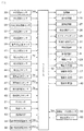
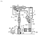
- FIG. 1 It is a block diagram of the air conditioning apparatus for vehicles of one Embodiment to which this invention is applied (heating mode, dehumidification heating mode, dehumidification cooling mode, and cooling mode). It is a block diagram of the electric circuit of the controller of the vehicle air conditioner of FIG. It is a block diagram at the time of the MAX cooling mode (maximum cooling mode) of the vehicle air conditioner of FIG. It is a timing chart of each apparatus explaining an example of the noise improvement control which the controller of FIG. 2 performs when switching from heating mode to dehumidification heating mode. It is a timing chart of each apparatus explaining an example of the noise improvement control which the controller of FIG. 2 performs when switching from dehumidification heating mode to heating mode.
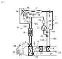
- FIG. 1 shows a configuration diagram of a vehicle air conditioner 1 according to an embodiment of the present invention.
- a vehicle according to an embodiment to which the present invention is applied is an electric vehicle (EV) in which an engine (internal combustion engine) is not mounted, and travels by driving an electric motor for traveling with electric power charged in a battery. Yes (both not shown), the vehicle air conditioner 1 of the present invention is also driven by the power of the battery.
- EV electric vehicle
- an engine internal combustion engine
- the vehicle air conditioner 1 of the embodiment performs a heating mode by a heat pump operation using a refrigerant circuit in an electric vehicle that cannot be heated by engine waste heat, and further includes a dehumidifying heating mode, a dehumidifying cooling mode, a cooling mode, Each operation mode of the MAX cooling mode (maximum cooling mode) is selectively executed.
- the present invention is effective not only for electric vehicles but also for so-called hybrid vehicles that use an engine and an electric motor for traveling, and is also applicable to ordinary vehicles that run on an engine. Needless to say.
- the vehicle air conditioner 1 performs air conditioning (heating, cooling, dehumidification, and ventilation) in a vehicle interior of an electric vehicle, and includes an electric compressor 2 that compresses refrigerant and vehicle interior air. Is provided in the air flow passage 3 of the HVAC unit 10 through which air is circulated, and the high-temperature and high-pressure refrigerant discharged from the compressor 2 flows in through the refrigerant pipe 13G, and dissipates the refrigerant into the vehicle compartment.
- an outdoor expansion valve 6 comprising an electric valve that decompresses and expands the refrigerant during heating, and functions as a radiator during cooling and functions as a radiator during heating, and exchanges heat between the refrigerant and the outside air so as to function as an evaporator during heating.
- An outdoor heat exchanger 7 that performs the above operation, an indoor expansion valve 8 that is an electric valve that decompresses and expands the refrigerant, and a heat absorber 9 that is provided in the air flow passage 3 and absorbs heat from outside the vehicle interior to the refrigerant during cooling and dehumidification.
- And accumulator 12 etc. Are sequentially connected by a refrigerant pipe 13, the refrigerant circuit R is formed.
- the refrigerant circuit R is filled with a predetermined amount of refrigerant and lubricating oil.
- the outdoor heat exchanger 7 is provided with an outdoor blower 15.
- the outdoor blower 15 exchanges heat between the outside air and the refrigerant by forcibly passing outside air through the outdoor heat exchanger 7, so that the outdoor air blower 15 can also be used outdoors even when the vehicle is stopped (that is, the vehicle speed is 0 km / h). It is comprised so that external air may be ventilated by the heat exchanger 7.
- the outdoor heat exchanger 7 has a receiver dryer section 14 and a supercooling section 16 sequentially on the downstream side of the refrigerant, and the refrigerant pipe 13A exiting from the outdoor heat exchanger 7 is received via an electromagnetic valve 17 opened during cooling.
- the refrigerant pipe 13 ⁇ / b> B connected to the dryer unit 14 and on the outlet side of the supercooling unit 16 is connected to the inlet side of the heat absorber 9 via the indoor expansion valve 8.
- the receiver dryer part 14 and the supercooling part 16 structurally constitute a part of the outdoor heat exchanger 7.
- the refrigerant pipe 13B between the subcooling section 16 and the indoor expansion valve 8 is provided in a heat exchange relationship with the refrigerant pipe 13C on the outlet side of the heat absorber 9, and constitutes an internal heat exchanger 19 together.
- the refrigerant flowing into the indoor expansion valve 8 through the refrigerant pipe 13B is cooled (supercooled) by the low-temperature refrigerant that has exited the heat absorber 9.
- the refrigerant pipe 13A exiting from the outdoor heat exchanger 7 is branched into a refrigerant pipe 13D, and this branched refrigerant pipe 13D is downstream of the internal heat exchanger 19 via an electromagnetic valve 21 opened during heating.
- the refrigerant pipe 13C is connected in communication.
- the refrigerant pipe 13 ⁇ / b> C is connected to the accumulator 12, and the accumulator 12 is connected to the refrigerant suction side of the compressor 2.
- the refrigerant pipe 13E on the outlet side of the radiator 4 is connected to the inlet side of the outdoor heat exchanger 7 via the outdoor expansion valve 6.
- a refrigerant pipe 13G between the discharge side of the compressor 2 and the inlet side of the radiator 4 is provided with a solenoid valve 30 (which constitutes a flow path switching device) that is closed during dehumidification heating and MAX cooling described later. Yes.
- the refrigerant pipe 13G is branched into a bypass pipe 35 on the upstream side of the electromagnetic valve 30, and the bypass pipe 35 is opened by the electromagnetic valve 40 (which also constitutes a flow path switching device) during dehumidifying heating and MAX cooling. )
- the electromagnetic valve 40 which also constitutes a flow path switching device during dehumidifying heating and MAX cooling.
- the bypass device 45 is configured by the bypass pipe 35, the electromagnetic valve 30, and the electromagnetic valve 40, the dehumidifying heating mode or the MAX for allowing the refrigerant discharged from the compressor 2 to directly flow into the outdoor heat exchanger 7 as will be described later. Switching between the cooling mode and the heating mode in which the refrigerant discharged from the compressor 2 flows into the radiator 4, the dehumidifying cooling mode, and the cooling mode can be performed smoothly.
- the air flow passage 3 on the air upstream side of the heat absorber 9 is formed with each of an outside air inlet and an inside air inlet (represented by the inlet 25 in FIG. 1).
- a suction switching damper 26 for switching the air introduced into the air flow passage 3 between the inside air (inside air circulation mode) which is air inside the passenger compartment and the outside air (outside air introduction mode) which is outside the passenger compartment.
- an indoor blower (blower fan) 27 for supplying the introduced inside air or outside air to the air flow passage 3 is provided on the air downstream side of the suction switching damper 26.
- 23 is an auxiliary heater as an auxiliary heating device provided in the vehicle air conditioner 1 of the embodiment.
- the auxiliary heater 23 of the embodiment is composed of a PTC heater which is an electric heater, and is provided in the air flow passage 3 on the air upstream side of the radiator 4 with respect to the air flow in the air flow passage 3. Yes.
- the auxiliary heater 23 When the auxiliary heater 23 is energized and generates heat, the air in the air flow passage 3 flowing into the radiator 4 through the heat absorber 9 is heated.
- the auxiliary heater 23 serves as a so-called heater core, which heats or complements the passenger compartment.
- air in the air flow passage 3 on the upstream side of the auxiliary heater 23 flows into the air flow passage 3 and assists air (inside air or outside air) in the air flow passage 3 after passing through the heat absorber 9.
- An air mix damper 28 is provided for adjusting the ratio of ventilation through the heater 23 and the radiator 4.
- FOOT foot
- VENT vent
- DEF (def) outlets represented by the outlet 29 as a representative in FIG.
- reference numeral 32 denotes a controller (ECU) as a control device composed of a microcomputer which is an example of a computer provided with a processor.
- the controller 32 detects the outside air temperature (Tam) of the vehicle.
- the outside air temperature sensor 33 for detecting the outside air humidity
- the HVAC suction temperature sensor 36 for detecting the temperature of the air sucked into the air flow passage 3 from the suction port 25, and the air (inside air) in the passenger compartment.
- An inside air temperature sensor 37 that detects the temperature
- an inside air humidity sensor 38 that detects the humidity of the air in the vehicle interior
- an indoor CO 2 concentration sensor 39 that detects the carbon dioxide concentration in the vehicle interior
- an air outlet from the air outlet 29 And a discharge pressure sensor 41 for detecting the discharge refrigerant pressure (discharge pressure Pd) of the compressor 2.
- a discharge temperature sensor 43 that detects the discharge refrigerant temperature of the compressor 2
- a suction pressure sensor 44 that detects the suction refrigerant pressure of the compressor 2
- a suction temperature sensor 55 that detects the suction refrigerant temperature of the compressor 2.
- radiator temperature sensor 46 that detects the temperature of the radiator 4 (the temperature of the air that has passed through the radiator 4 or the temperature of the radiator 4 itself: the radiator temperature TH), and the refrigerant pressure (the radiator of the radiator 4).
- 4 or a radiator pressure sensor 47 that detects the pressure of the refrigerant immediately after exiting the radiator 4: the radiator pressure PCI, and the temperature of the heat absorber 9 (the temperature of the air passing through the heat absorber 9 or the heat absorption).
- a heat absorber pressure sensor 49 for detecting the amount of solar radiation into the passenger compartment
- a photosensor-type solar radiation sensor 51 for detecting the moving speed (vehicle speed) of the vehicle, an air conditioning (air conditioner) operation unit 53 for setting a set temperature and an operation mode, and outdoor heat
- An outdoor heat exchanger temperature sensor 54 for detecting the temperature of the exchanger 7 (the temperature of the refrigerant immediately after leaving the outdoor heat exchanger 7 or the temperature of the outdoor heat exchanger 7 itself: the outdoor heat exchanger temperature TXO);
- the pressure of the outdoor heat exchanger pressure sensor 56 that detects the refrigerant pressure of the outdoor heat exchanger 7 (the pressure of the refrigerant in the outdoor heat exchanger 7 or immediately after exiting the outdoor heat exchanger 7: outdoor heat exchanger pressure PXO).
- the input of the controller 32 further includes an auxiliary heater temperature sensor for detecting the temperature of the auxiliary heater 23 (the temperature of the air immediately after being heated by the auxiliary heater 23 or the temperature of the auxiliary heater 23 itself: the auxiliary heater temperature Tptc). 50 outputs are also connected.
- the output of the controller 32 includes the compressor 2, the outdoor blower 15, the indoor blower (blower fan) 27, the suction switching damper 26, the air mix damper 28, the outlet switching damper 31, and the outdoor expansion.
- the controller 32 switches between the operation modes of the heating mode, the dehumidifying heating mode, the dehumidifying cooling mode, the cooling mode, and the MAX cooling mode (maximum cooling mode).
- the controller 32 switches between the operation modes of the heating mode, the dehumidifying heating mode, the dehumidifying cooling mode, the cooling mode, and the MAX cooling mode (maximum cooling mode).
- heating mode When the heating mode is selected by the controller 32 (auto mode) or by the manual operation (manual mode) to the air conditioning operation unit 53, the controller 32 opens the solenoid valve 21 (for heating) and opens the solenoid valve. Close 17 (for cooling). Further, the electromagnetic valve 30 (for dehumidification) is opened, and the electromagnetic valve 40 (for dehumidification) is closed. Then, the compressor 2 and each of the blowers 15 and 27 are operated, and the air mix damper 28 is blown out from the indoor blower 27 and passes through the heat absorber 9 as shown by a broken line in FIG. It is assumed that air is passed through the auxiliary heater 23 and the radiator 4.
- the high-temperature and high-pressure gas refrigerant discharged from the compressor 2 flows into the radiator 4 from the refrigerant pipe 13G via the electromagnetic valve 30. Since the air in the airflow passage 3 is passed through the radiator 4, the air in the airflow passage 3 is converted into the high-temperature refrigerant in the radiator 4 (when the auxiliary heater 23 operates, the auxiliary heater 23 and the radiator 4. On the other hand, the refrigerant in the radiator 4 is cooled by being deprived of heat by the air, and is condensed and liquefied. The refrigerant liquefied in the radiator 4 exits the radiator 4 and then reaches the outdoor expansion valve 6 through the refrigerant pipe 13E.
- the refrigerant flowing into the outdoor expansion valve 6 is decompressed there and then flows into the outdoor heat exchanger 7.
- the refrigerant flowing into the outdoor heat exchanger 7 evaporates, and pumps up heat from the outside air that is ventilated by traveling or by the outdoor blower 15. That is, the refrigerant circuit R becomes a heat pump.
- the low-temperature refrigerant exiting the outdoor heat exchanger 7 enters the accumulator 12 from the refrigerant pipe 13C through the refrigerant pipe 13A, the electromagnetic valve 21 and the refrigerant pipe 13D, and is separated into gas and liquid there. Repeated circulation inhaled.
- the controller 32 calculates a target radiator pressure PCO (target value of the radiator pressure PCI) from a target radiator temperature TCO (target value of the radiator temperature TH) calculated from a target outlet temperature TAO described later, and this target heat dissipation.
- the number of revolutions of the compressor 2 is controlled based on the compressor pressure PCO and the refrigerant pressure of the radiator 4 detected by the radiator pressure sensor 47 (radiator pressure PCI; high pressure of the refrigerant circuit R).
- the controller 32 determines the valve opening degree of the outdoor expansion valve 6 based on the temperature of the radiator 4 (the radiator temperature TH) detected by the radiator temperature sensor 46 and the radiator pressure PCI detected by the radiator pressure sensor 47. And the supercooling degree SC of the refrigerant at the outlet of the radiator 4 is controlled.
- the auxiliary heater 23 is disposed on the air upstream side of the radiator 4, the air flowing through the air flow passage 3 is vented to the auxiliary heater 23 before the radiator 4.
- the auxiliary heater 23 is disposed on the air downstream side of the radiator 4
- the auxiliary heater 23 is configured by a PCT heater as in the embodiment, the temperature of the air flowing into the auxiliary heater 23 is determined by the radiator. 4, the resistance value of the PTC heater increases, the current value also decreases, and the heat generation amount decreases.
- the controller 32 opens the electromagnetic valve 17 and closes the electromagnetic valve 21. Further, the electromagnetic valve 30 is closed, the electromagnetic valve 40 is opened, and the valve opening degree of the outdoor expansion valve 6 is fully closed. Then, the compressor 2 and each of the blowers 15 and 27 are operated, and the air mix damper 28 is blown out from the indoor blower 27 and passes through the heat absorber 9 as shown by a broken line in FIG. It is assumed that air is passed through the auxiliary heater 23 and the radiator 4.
- the high-temperature and high-pressure gas refrigerant discharged from the compressor 2 to the refrigerant pipe 13G flows into the bypass pipe 35 without going to the radiator 4, passes through the electromagnetic valve 40, and is connected to the refrigerant pipe on the downstream side of the outdoor expansion valve 6. 13E.
- the outdoor expansion valve 6 since the outdoor expansion valve 6 is fully closed, the refrigerant flows into the outdoor heat exchanger 7.
- the refrigerant flowing into the outdoor heat exchanger 7 is cooled and condensed by running there or by the outside air ventilated by the outdoor blower 15.
- the refrigerant that has exited the outdoor heat exchanger 7 sequentially flows from the refrigerant pipe 13 ⁇ / b> A through the electromagnetic valve 17 into the receiver dryer unit 14 and the supercooling unit 16.
- the refrigerant is supercooled.
- the refrigerant that has exited the supercooling section 16 of the outdoor heat exchanger 7 enters the refrigerant pipe 13 ⁇ / b> B, reaches the indoor expansion valve 8 through the internal heat exchanger 19. After the refrigerant is depressurized by the indoor expansion valve 8, it flows into the heat absorber 9 and evaporates.
- the air blown out from the indoor blower 27 by the heat absorption action at this time is cooled, and moisture in the air condenses and adheres to the heat absorber 9, so that the air in the air flow passage 3 is cooled, and Dehumidified.
- the refrigerant evaporated in the heat absorber 9 reaches the accumulator 12 through the refrigerant pipe 13C through the internal heat exchanger 19, and repeats circulation that is sucked into the compressor 2 there through.
- the valve opening degree of the outdoor expansion valve 6 is fully closed, it is possible to suppress or prevent inconvenience that the refrigerant discharged from the compressor 2 flows backward from the outdoor expansion valve 6 into the radiator 4. It becomes. Thereby, the fall of a refrigerant
- the air cooled and dehumidified by the heat absorber 9 is further heated in the process of passing through the auxiliary heater 23 and the temperature rises, so that the dehumidifying heating in the passenger compartment is performed.
- the controller 32 controls the rotational speed of the compressor 2 on the basis of the temperature of the heat absorber 9 (heat absorber temperature Te) detected by the heat absorber temperature sensor 48 and the target heat absorber temperature TEO that is the target value, and the auxiliary heater temperature.
- auxiliary heater 23 By controlling the energization (heat generation) of the auxiliary heater 23 based on the auxiliary heater temperature Tptc detected by the sensor 50 and the target radiator temperature TCO described above, while appropriately cooling and dehumidifying the air in the heat absorber 9, A decrease in the temperature of the air blown from the outlet 29 into the passenger compartment by heating by the auxiliary heater 23 is accurately prevented. As a result, it is possible to control the temperature to an appropriate heating temperature while dehumidifying the air blown into the vehicle interior, and it is possible to realize comfortable and efficient dehumidification heating in the vehicle interior.
- the air mix damper 28 is in a state where all the air in the air flow passage 3 is passed through the auxiliary heater 23 and the radiator 4, so that the air passing through the heat absorber 9 is efficiently assisted. Heating by the heater 23 can improve the energy saving performance, and the controllability of the dehumidifying heating air conditioning can also be improved.
- the auxiliary heater 23 is disposed on the air upstream side of the radiator 4, the air heated by the auxiliary heater 23 passes through the radiator 4. In this dehumidifying heating mode, the refrigerant is supplied to the radiator 4. Therefore, the disadvantage that the radiator 4 absorbs heat from the air heated by the auxiliary heater 23 is also eliminated.
- the controller 32 opens the electromagnetic valve 17 and closes the electromagnetic valve 21. Further, the electromagnetic valve 30 is opened and the electromagnetic valve 40 is closed. Then, the compressor 2 and each of the blowers 15 and 27 are operated, and the air mix damper 28 is blown out from the indoor blower 27 and passes through the heat absorber 9 as shown by a broken line in FIG. It is assumed that air is passed through the auxiliary heater 23 and the radiator 4.
- the high-temperature and high-pressure gas refrigerant discharged from the compressor 2 flows into the radiator 4 from the refrigerant pipe 13G via the electromagnetic valve 30. Since the air in the air flow passage 3 is passed through the radiator 4, the air in the air flow passage 3 is heated by the high-temperature refrigerant in the radiator 4, while the refrigerant in the radiator 4 heats the air. It is deprived and cooled, and condensates.
- the refrigerant that has exited the radiator 4 reaches the outdoor expansion valve 6 through the refrigerant pipe 13E, and flows into the outdoor heat exchanger 7 through the outdoor expansion valve 6 that is controlled to open.
- the refrigerant flowing into the outdoor heat exchanger 7 is cooled and condensed by running there or by the outside air ventilated by the outdoor blower 15.
- the refrigerant that has exited the outdoor heat exchanger 7 sequentially flows from the refrigerant pipe 13 ⁇ / b> A through the electromagnetic valve 17 into the receiver dryer unit 14 and the supercooling unit 16. Here, the refrigerant is supercooled.
- the refrigerant that has exited the supercooling section 16 of the outdoor heat exchanger 7 enters the refrigerant pipe 13 ⁇ / b> B, reaches the indoor expansion valve 8 through the internal heat exchanger 19. After the refrigerant is depressurized by the indoor expansion valve 8, it flows into the heat absorber 9 and evaporates.
- the air Since the moisture in the air blown out from the indoor blower 27 by the heat absorption action at this time condenses and adheres to the heat absorber 9, the air is cooled and dehumidified.
- the refrigerant evaporated in the heat absorber 9 reaches the accumulator 12 through the refrigerant pipe 13C through the internal heat exchanger 19, and repeats circulation that is sucked into the compressor 2 there through.
- the controller 32 does not energize the auxiliary heater 23, so the air cooled by the heat absorber 9 is reheated in the process of passing through the radiator 4 (the heat dissipation capability is lower than that during heating). The As a result, dehumidifying and cooling in the passenger compartment is performed.
- the controller 32 controls the rotational speed of the compressor 2 based on the temperature of the heat absorber 9 (heat absorber temperature Te) detected by the heat absorber temperature sensor 48, and also uses the outdoor expansion valve based on the high pressure of the refrigerant circuit R described above. 6 is controlled to control the refrigerant pressure of the radiator 4 (radiator pressure PCI).
- the controller 32 fully opens the valve opening degree of the outdoor expansion valve 6 in the dehumidifying and cooling mode.
- the controller 32 controls the air mix damper 28, and the air in the air flow passage 3 after being blown out from the indoor blower 27 and passing through the heat absorber 9 as shown by a solid line in FIG. The rate of ventilation through the vessel 4 is adjusted.
- the controller 32 does not energize the auxiliary heater 23.
- the high-temperature and high-pressure gas refrigerant discharged from the compressor 2 flows into the radiator 4 from the refrigerant pipe 13G via the electromagnetic valve 30, and the refrigerant exiting the radiator 4 passes through the refrigerant pipe 13E and the outdoor expansion valve 6.
- the outdoor expansion valve 6 since the outdoor expansion valve 6 is fully opened, the refrigerant passes through it and flows into the outdoor heat exchanger 7 as it is, where it is cooled by air or by outside air that is ventilated by the outdoor blower 15 and condensed. Liquefaction.
- the refrigerant that has exited the outdoor heat exchanger 7 sequentially flows from the refrigerant pipe 13 ⁇ / b> A through the electromagnetic valve 17 into the receiver dryer unit 14 and the supercooling unit 16. Here, the refrigerant is supercooled.
- the refrigerant that has exited the supercooling section 16 of the outdoor heat exchanger 7 enters the refrigerant pipe 13 ⁇ / b> B, reaches the indoor expansion valve 8 through the internal heat exchanger 19. After the refrigerant is depressurized by the indoor expansion valve 8, it flows into the heat absorber 9 and evaporates.
- the air blown out from the indoor blower 27 by the heat absorption action at this time is cooled. Further, moisture in the air condenses and adheres to the heat absorber 9.
- the refrigerant evaporated in the heat absorber 9 reaches the accumulator 12 through the refrigerant pipe 13C through the internal heat exchanger 19, and repeats circulation that is sucked into the compressor 2 there through. Since the air cooled and dehumidified by the heat absorber 9 is blown into the vehicle interior from the air outlet 29 (partly passes through the radiator 4 to exchange heat), the vehicle interior is thereby cooled. become.
- the controller 32 rotates the compressor 2 based on the temperature of the heat absorber 9 (heat absorber temperature Te) detected by the heat absorber temperature sensor 48 and the target heat absorber temperature TEO that is the target value. To control.
- MAX cooling mode (maximum cooling mode)
- the controller 32 opens the electromagnetic valve 17 and closes the electromagnetic valve 21. Further, the electromagnetic valve 30 is closed, the electromagnetic valve 40 is opened, and the valve opening degree of the outdoor expansion valve 6 is fully closed. Then, the compressor 2 and the blowers 15 and 27 are operated, and the air mix damper 28 keeps the air in the air flow passage 3 from passing through the auxiliary heater 23 and the radiator 4 as shown in FIG. However, there is no problem even if it is ventilated somewhat. Further, the controller 32 does not energize the auxiliary heater 23.
- the high-temperature and high-pressure gas refrigerant discharged from the compressor 2 to the refrigerant pipe 13G flows into the bypass pipe 35 without going to the radiator 4, passes through the electromagnetic valve 40, and is connected to the refrigerant pipe on the downstream side of the outdoor expansion valve 6. 13E.
- the outdoor expansion valve 6 since the outdoor expansion valve 6 is fully closed, the refrigerant flows into the outdoor heat exchanger 7.
- the refrigerant flowing into the outdoor heat exchanger 7 is cooled and condensed by running there or by the outside air ventilated by the outdoor blower 15.
- the refrigerant that has exited the outdoor heat exchanger 7 sequentially flows from the refrigerant pipe 13 ⁇ / b> A through the electromagnetic valve 17 into the receiver dryer unit 14 and the supercooling unit 16.
- the refrigerant is supercooled.
- the refrigerant that has exited the supercooling section 16 of the outdoor heat exchanger 7 enters the refrigerant pipe 13 ⁇ / b> B, reaches the indoor expansion valve 8 through the internal heat exchanger 19. After the refrigerant is depressurized by the indoor expansion valve 8, it flows into the heat absorber 9 and evaporates. The air blown out from the indoor blower 27 by the heat absorption action at this time is cooled. In addition, since moisture in the air condenses and adheres to the heat absorber 9, the air in the air flow passage 3 is dehumidified.
- the refrigerant evaporated in the heat absorber 9 reaches the accumulator 12 through the refrigerant pipe 13C through the internal heat exchanger 19, and repeats circulation that is sucked into the compressor 2 there through.
- the outdoor expansion valve 6 since the outdoor expansion valve 6 is fully closed, similarly, it is possible to suppress or prevent the disadvantage that the refrigerant discharged from the compressor 2 flows backward from the outdoor expansion valve 6 into the radiator 4. . Thereby, the fall of a refrigerant
- the high-temperature refrigerant flows through the radiator 4 in the cooling mode described above, direct heat conduction from the radiator 4 to the HVAC unit 10 occurs not a little, but in this MAX cooling mode, the refrigerant flows into the radiator 4. Therefore, the air in the air flow passage 3 from the heat absorber 9 is not heated by the heat transmitted from the radiator 4 to the HVAC unit 10. Therefore, powerful cooling of the passenger compartment is performed, and particularly in an environment where the outside air temperature Tam is high, the passenger compartment can be quickly cooled to realize comfortable air conditioning in the passenger compartment.
- the controller 32 rotates the compressor 2 based on the temperature of the heat absorber 9 (heat absorber temperature Te) detected by the heat absorber temperature sensor 48 and the target heat absorber temperature TEO that is the target value. Control the number.
- (6) Switching of operation mode The air flowing through the air flow passage 3 is cooled by the heat absorber 9 and heated by the heat radiator 4 (and the auxiliary heater 23) in each of the operation modes (adjusted by the air mix damper 28). ) And is blown out from the air outlet 29 into the passenger compartment.
- the controller 32 is set by the air-conditioning operation unit 53, the outside air temperature Tam detected by the outside air temperature sensor 33, the temperature in the vehicle interior detected by the inside air temperature sensor 37, the blower voltage, the amount of solar radiation detected by the solar radiation sensor 51, and the like.
- the target blowout temperature TAO is calculated based on the target passenger compartment temperature (set temperature) in the passenger compartment, and the temperature of the air blown from the blowout port 29 is controlled to this target blowout temperature TAO by switching each operation mode.
- the controller 32 determines whether the outside air temperature Tam, the humidity in the vehicle interior, the target outlet temperature TAO, the radiator temperature TH, the target radiator temperature TCO, the heat absorber temperature Te, the target heat absorber temperature TEO, or the dehumidification request in the vehicle interior. By switching each operation mode based on parameters such as, etc., it switches between heating mode, dehumidifying heating mode, dehumidifying cooling mode, cooling mode and MAX cooling mode accurately according to the environmental conditions and necessity of dehumidification. In addition, efficient cabin air conditioning is realized. (7) Noise improvement control when switching from heating mode to dehumidifying heating mode Next, referring to FIG.
- the timing chart of FIG. 4 shows the pressure difference ⁇ Pdx before and after the electromagnetic valve 40 (second on-off valve of the present invention) when switching from the heating mode to the dehumidifying heating mode, and the blowing temperature detected by the blowing temperature sensor 41 (described above).
- the pressure difference ⁇ Pdx before and after the electromagnetic valve 40 (second on-off valve) is determined by the pressure Pd on the upstream side (front) of the refrigerant of the electromagnetic valve 40 detected by the discharge pressure sensor 42 and the outdoor heat exchanger temperature sensor 54.
- the outdoor heat exchanger pressure PXO on the downstream side (rear side) of the solenoid valve 40 converted from the temperature of the refrigerant immediately after coming out of the outdoor heat exchanger 7 to be detected (outdoor heat exchanger temperature TXO) (outdoor as in the embodiment)
- the controller 32 calculates.
- the controller 32 also calculates a pressure difference ⁇ Pix before and after the electromagnetic valve 30 (first on-off valve) in noise improvement control described later.
- the controller 32 is on the refrigerant upstream side of the solenoid valve 21 (outdoor heat exchanger temperature TXO) converted from the refrigerant temperature (outdoor heat exchanger temperature TXO) immediately after coming out of the outdoor heat exchanger 7 detected by the outdoor heat exchanger temperature sensor 54.
- Previous heat exchanger pressure PXO when the outdoor heat exchanger pressure sensor 56 is provided as in the embodiment, the outdoor heat exchanger pressure PCO detected by the outdoor heat exchanger pressure sensor 56 may be used.
- the controller 32 executes noise improvement control described below when switching the operation mode from the heating mode to the dehumidifying heating mode.
- the controller 32 first causes the auxiliary heater 23 to generate heat and increase its output (energization amount or heat generation amount). In this case, the controller 32 increases the output to the predetermined value D (FIG.
- the controller 32 opens the electromagnetic valve 17 and closes the electromagnetic valve 21.
- the refrigerant circuit R is switched to a state in which the refrigerant discharged from the outdoor heat exchanger 7 flows to the heat absorber 9 via the receiver dryer section 14, the supercooling section 16, the internal heat exchanger 19, and the indoor expansion valve 8.
- the controller 32 then controls the output of the auxiliary heater 23 to be the target value C in the dehumidifying and heating mode described above.
- the controller 32 sets the pressure difference Pdx before and after the electromagnetic valve 40 to the predetermined value A (for example, before switching the electromagnetic valve 40 and the electromagnetic valve 30).
- the opening degree of the outdoor expansion valve 6 is increased and the rotational speed NC of the compressor 2 is adjusted (controlled in a decreasing direction) so as to be equal to or lower than 0.2 MPa.
- the outdoor heat exchanger pressure PXO increases, and by controlling the rotational speed NC of the compressor 2 to decrease, the discharge pressure Pd decreases.
- the pressure difference Pdx before and after the valve 40 becomes smaller.
- the controller 32 opens the electromagnetic valve 40, closes the electromagnetic valve 30, fully closes the outdoor expansion valve 6, and controls the compressor 2. Is controlled during dehumidifying heating to shift to the air conditioning operation in the dehumidifying heating mode. (7-2) Noise improvement control when switching from heating mode to dehumidifying heating mode (part 2)
- the controller 32 increases the valve opening degree of the outdoor expansion valve 6 so that the pressure difference ⁇ Pdx before and after the electromagnetic valve 40 is equal to or less than the predetermined value A, and the compressor 2
- the present invention is not limited to this, and the valve opening degree of the outdoor expansion valve 6 is fully opened (FIG.
- the rotation speed NC of the compressor 2 is a predetermined low speed that is a predetermined low value.
- NC1 (FIG. 4. For example, 800 rpm) may be used. Since the outdoor expansion valve 6 is fully opened and the rotational speed NC of the compressor 2 is controlled to a low predetermined rotational speed NC1, the outdoor heat exchanger pressure PXO increases and the discharge pressure Pd decreases. The pressure difference Pdx before and after becomes smaller. Also in this case, when the pressure difference ⁇ Pdx is reduced to the predetermined value A or less, the controller 32 opens the electromagnetic valve 40, closes the electromagnetic valve 30, and fully closes the outdoor expansion valve 6, thereby dehumidifying. Transition to air conditioning operation in heating mode.
- the controller 32 fully opens the outdoor expansion valve 6 and sets the rotational speed NC of the compressor 2 to the predetermined rotational speed NC1, for a predetermined time (for example, 10 seconds, etc. FIG. 4). After the elapse of time, the electromagnetic valve 40 may be opened, the electromagnetic valve 30 may be closed, and the outdoor expansion valve 6 may be fully closed to start the air conditioning operation in the dehumidifying heating mode.
- the controller 32 when switching the operation mode from the heating mode to the dehumidifying heating mode, the controller 32 reduces the pressure difference ⁇ Pdx before and after the electromagnetic valve 40 (second on-off valve), then opens the electromagnetic valve 40, and opens the electromagnetic valve 30. Since the noise improvement control for closing the (first on-off valve) and fully closing the outdoor expansion valve 6 is performed, when switching from the heating mode to the dehumidifying heating mode, when the electromagnetic valve 40 is opened, bypass is performed. It is possible to greatly suppress or eliminate the sudden flow of the refrigerant through the pipe 35 toward the outdoor heat exchanger 7 side. Thereby, at the time of switching from the heating mode to the dehumidifying heating mode, noise generated when the electromagnetic valve 40 is opened can be eliminated or reduced.
- the controller 32 increases the valve opening of the outdoor expansion valve 6 and rotates the compressor 2.
- the pressure difference ⁇ Pdx before and after the electromagnetic valve 40 is reduced, and when the pressure difference ⁇ Pdx becomes a predetermined value A or less, the electromagnetic valve 40 is opened, the electromagnetic valve 30 is closed, and the outdoor expansion is performed. Since the valve 6 is fully closed, the pressure on the refrigerant downstream side of the electromagnetic valve 40 is increased by increasing the valve opening of the outdoor expansion valve 6, and the refrigerant upstream of the electromagnetic valve 40 is controlled by controlling the rotational speed NC of the compressor 2.
- the noise improvement control noise improvement control at the time of switching from the heating mode to the dehumidifying heating mode (No. 2), (No.
- the controller 32 fully opens the outdoor expansion valve 6 and the compressor 2
- the pressure difference ⁇ Pdx before and after the electromagnetic valve 40 is reduced by setting the rotational speed NC to a predetermined low value, and when the pressure difference ⁇ Pdx becomes a predetermined value A or less, or the rotational speed NC of the compressor 2 Since the solenoid valve 40 is opened, the solenoid valve 30 is closed, and the outdoor expansion valve 6 is fully closed after a lapse of a predetermined time since the low value is reduced, the outdoor expansion valve 6 is fully opened.
- the pressure difference ⁇ Pdx before and after the solenoid valve 40 is quickly reduced by raising the pressure and lowering the pressure upstream of the refrigerant of the solenoid valve 40 by reducing the rotational speed NC of the compressor 2 and switching to the dehumidifying heating mode accurately. And cut Effectively eliminate noise generated during recombination, or made so that it is possible to reduce.
- the noise improvement control since the rotational speed NC of the compressor 2 is lowered, there is a risk that the temperature of the air blown into the passenger compartment (blowing temperature) is lowered and the comfort is deteriorated.
- the controller 32 switches from the heating mode to the dehumidifying heating mode, first, the auxiliary heater 23 generates heat, and when the temperature Tptc of the auxiliary heater 23 becomes a predetermined value B or more, the outdoor heat Since the solenoid valve 17 and the solenoid valve 21 are switched to a state where the refrigerant discharged from the exchanger 7 flows to the heat absorber 9, the control of the outdoor expansion valve 6 and the compressor 2 in the noise improvement control is started. As shown in Fig. 5, the blowout temperature is kept substantially constant even in the process of switching from the heating mode to the dehumidifying heating mode.
- Noise improvement control at the time of switching from the dehumidifying and heating mode to the heating mode is suppressed, and it becomes possible to implement
- Noise improvement control executed by the controller 32 will be described.
- the timing chart of FIG. 5 shows the pressure difference ⁇ Pxs before and after the electromagnetic valve 21 (the third on-off valve of the present invention) when switching from the dehumidifying heating mode to the heating mode, and the electromagnetic valve 30 (the first on-off opening of the present invention).
- the pressure difference ⁇ Pxs before and after the solenoid valve 21 is also a large value as shown in FIG. Therefore, when the electromagnetic valve 21 that is closed in the dehumidifying heating mode is opened to enter the heating mode with such a pressure difference, the refrigerant suddenly flows from the outdoor heat exchanger 7 through the electromagnetic valve 21 toward the inlet side of the accumulator 12. Similarly, a large sound (noise) is generated in the solenoid valve 21. Therefore, the controller 32 executes the noise improvement control described below also when switching the operation mode from the dehumidifying heating mode to the heating mode.
- the controller 32 switches from the dehumidifying heating mode to the heating mode, first, the output (energization amount or heat generation amount) of the auxiliary heater 23 is increased. In this case, the controller 32 increases the output of the auxiliary heater 23 to a predetermined value D (FIG. 5) that is higher by a predetermined value than the target value C (FIG. 5) of the output of the auxiliary heater 23 executed in the dehumidifying heating mode. Let Thereby, auxiliary heater temperature Tptc rises. In addition, before switching the solenoid valve 40 and the solenoid valve 30, the controller 32 expands the outdoor so that the pressure difference Pix before and after the solenoid valve 30 is equal to or less than a predetermined value A (for example, 0.2 MPa).
- a predetermined value A for example, 0.2 MPa
- the valve 6 is shifted from the closed state to the opened state, and the rotational speed NC of the compressor 2 is adjusted (controlled in a decreasing direction).
- the radiator pressure PCI increases, and the discharge pressure Pd decreases by controlling the rotational speed NC of the compressor 2 so that the pressure difference before and after the solenoid valve 30 is reduced.
- the controller 32 opens the electromagnetic valve 30 and closes the electromagnetic valve 40. Since the solenoid valve 30 is opened and the solenoid valve 40 is closed, the refrigerant is depressurized by the outdoor expansion valve 6 via the radiator 4, and therefore the outdoor heat exchanger pressure PXO is reduced.
- the controller 32 opens the outdoor expansion valve 6 so that the pressure difference ⁇ Pix before and after the electromagnetic valve 30 is equal to or less than the predetermined value A, and the rotational speed NC of the compressor 2 is set.
- the compressor 2 may be further stopped (that is, the outdoor expansion valve 6 is opened and the compressor 2 is stopped). (FIG. 5).
- the radiator pressure PCI and the discharge pressure Pd are in an equilibrium state, so the pressure difference Pix before and after the electromagnetic valve 30 becomes smaller.
- the controller 32 opens the electromagnetic valve 30 and closes the electromagnetic valve 40. Then, the pressure difference ⁇ Pxs before and after the electromagnetic valve 21 becomes equal to or less than a predetermined value E, the electromagnetic valve 17 is closed, the electromagnetic valve 21 is opened, the compressor 2 is started, and the output of the auxiliary heater 23 is also reduced (in the embodiment) The output is stopped), and the air-conditioning operation in the heating mode is started.
- the outdoor expansion valve 6 may be shifted to the control state in the heating mode by the controller 32 from the start of the noise improvement control in this case (FIG.
- the compressor 2 may be stopped ( FIG. 5). Since the outdoor expansion valve 6 is opened and the control state during heating is set, and the compressor 2 is stopped, the radiator pressure PCI and the discharge pressure Pd are in an equilibrium state, so the pressure difference Pix before and after the electromagnetic valve 30 is It gets smaller. When the pressure difference ⁇ Pix is reduced to a predetermined value A or less, the controller 32 opens the electromagnetic valve 30 and closes the electromagnetic valve 40.
- the controller 32 sets the outdoor expansion valve 6 to the control state during heating, and after a predetermined time (for example, 10 seconds, FIG. 5) has elapsed since the compressor 2 was stopped.
- the electromagnetic valve 30 may be opened and the electromagnetic valve 40 may be closed.
- the pressure difference ⁇ Pxs before and after the solenoid valve 21 becomes equal to or less than the predetermined value E
- the solenoid valve 17 is closed, the solenoid valve 21 is opened, the compressor 2 is started, and the output of the auxiliary heater 23 is also reduced (implementation). In the example, the output is stopped), and the air-conditioning operation in the heating mode is started.
- the controller 32 reduces the pressure difference ⁇ Pix before and after the electromagnetic valve 30 and then performs noise improvement control that opens the electromagnetic valve 30 and closes the electromagnetic valve 40.
- the controller 32 opens the outdoor expansion valve 6 in the noise improvement control, and When the rotational speed NC of the compressor 2 is controlled or the pressure difference ⁇ Pix before and after the electromagnetic valve 30 is reduced by stopping the compressor 2, and the pressure difference ⁇ Pix becomes a predetermined value A or less, Since the electromagnetic valve 30 is opened and the electromagnetic valve 40 is closed, the pressure on the downstream side of the refrigerant of the electromagnetic valve 30 is increased by opening the outdoor expansion valve 6, and the rotational speed of the compressor 2 is controlled or stopped.
- the controller 32 controls the outdoor expansion valve 6 in the heating mode in the noise improvement control.
- the pressure difference ⁇ Pix before and after the solenoid valve 30 is reduced by stopping the compressor 2 and the compressor 2 is stopped when the pressure difference ⁇ Pix becomes a predetermined value A or less.
- the solenoid valve 30 Since the solenoid valve 30 is opened and the solenoid valve 40 is closed after a lapse of a predetermined time from the beginning, the pressure on the refrigerant downstream side of the solenoid valve 30 is increased by opening the outdoor expansion valve 6, and the refrigerant upstream side of the solenoid valve 30 is stopped by stopping the compressor 2.
- the pressure difference ⁇ Pix before and after the solenoid valve 30 is rapidly reduced by reducing the pressure of the solenoid valve 30 to accurately switch to the heating mode, and noise generated at the time of switching can be effectively eliminated or reduced. So as you can.
- the controller 32 opens the electromagnetic valve 30 and closes the electromagnetic valve 40, and when the pressure difference ⁇ Pxs before and after the electromagnetic valve 21 becomes a predetermined value E or less, Since the solenoid valve 21 is opened and the solenoid valve 17 is opened, when switching from the dehumidifying and heating mode to the heating mode, the refrigerant may suddenly flow toward the compressor 2 when the solenoid valve 21 is opened. It can be greatly suppressed or eliminated. Thereby, at the time of switching from the dehumidifying heating mode to the heating mode, noise generated when the electromagnetic valve 21 is opened can be eliminated or reduced.
- the rotational speed NC of the compressor 2 is reduced or stopped, so that there is a risk that the temperature of the air blown into the passenger compartment (blowing temperature) is lowered and the comfort is deteriorated. is there.
- the controller 32 when switching from the dehumidifying and heating mode to the heating mode, the controller 32 first increases the heat generation of the auxiliary heater 23 and opens (opens) the electromagnetic valve 21 and then decreases (stops) the heat generation. As shown in FIG. 5, the blowing temperature is maintained substantially constant even in the process of switching from the dehumidifying and heating mode to the heating mode.
- the controller 32 reduces the heat generation of the auxiliary heater 23 (stops in the embodiment) after opening the electromagnetic valve 21.
- the auxiliary heater 23 is caused to generate heat even after shifting to the heating mode, for example, the stage where the radiator pressure PCI (high pressure side pressure, which may be the radiator temperature TH) has risen to a predetermined value (may be a target value) or more.
- the heat generation may be reduced (including stoppage).
- the vehicle interior can be heated by the radiator 4 and the auxiliary heater 23 until the high-pressure side pressure of the refrigerant circuit R rises. It is possible to more reliably eliminate the decrease and to realize comfortable vehicle interior heating.
- the noise improvement control at the time of switching from the dehumidifying heating mode to the heating mode as described above the air flow rate of the indoor blower 27 is reduced, and after shifting to the heating mode, the radiator pressure PCI (or the radiator temperature TH is the target value). It may be made to return to the original air volume after it has risen to 1. As the air volume of the indoor blower 27 decreases, it is possible to further suppress the decrease in the blowing temperature.
- the present invention is applied to the vehicle air conditioner 1 that switches between the operation modes of the heating mode, the dehumidifying heating mode, the dehumidifying cooling mode, the cooling mode, and the MAX cooling mode, but is not limited thereto.
- the present invention is also effective for a vehicle air conditioner that switches between a heating mode and a dehumidifying heating mode.
- the switching control of each operation mode shown in the embodiment is not limited thereto, and the outside air temperature Tam, the humidity in the passenger compartment, the target outlet temperature TAO, depending on the capability and usage environment of the vehicle air conditioner, Adopt any one of parameters such as radiator temperature TH, target radiator temperature TCO, heat absorber temperature Te, target heat absorber temperature TEO, presence / absence of dehumidification request in vehicle interior, or a combination thereof, or all of them. Appropriate conditions should be set.
- the auxiliary heating device is not limited to the auxiliary heater 23 shown in the embodiment, and a heat medium circulation circuit for heating the air in the air flow passage by circulating the heat medium heated by the heater, an engine You may utilize the heater core etc. which circulate the radiator water heated by.
- the configuration of the refrigerant circuit R described in each of the above embodiments is not limited thereto, and it is needless to say that the refrigerant circuit R can be changed without departing from the gist of the present invention.
Landscapes
- Engineering & Computer Science (AREA)
- Physics & Mathematics (AREA)
- Mechanical Engineering (AREA)
- Thermal Sciences (AREA)
- General Engineering & Computer Science (AREA)
- Air-Conditioning For Vehicles (AREA)
Abstract
Provided is an air-conditioning device for vehicle, comprising an opening/closing valve and a bypass pipe that bypasses a radiator and an outdoor expansion valve, wherein the noise generated when opening the opening/closing valve when switching between heating mode and dehumidifying heating mode is reduced or eliminated. Two modes are executed: a heating mode in which solenoid valve (30) is opened and solenoid valve (40) is closed, and a dehumidifying heating mode in which the solenoid valve (30) is closed and the solenoid valve (40) is opened and heat is dissipated from the coolant in an outdoor heat exchanger (7), heat is absorbed by a heat sink (9), and an auxiliary heater (23) is made to generate heat. When switching from heating mode to dehumidifying heating mode, after reducing the pressure differential before and after the solenoid valve (40), control is performed to reduce the noise level associated with the opening of the solenoid valve (40) and the closing of the solenoid valve (30).
Description
本発明は、車両の車室内を空調するヒートポンプ方式の空気調和装置、特にハイブリッド自動車や電気自動車に適用可能な空気調和装置に関するものである。
The present invention relates to a heat pump type air conditioner that air-conditions the interior of a vehicle, and more particularly to an air conditioner that can be applied to a hybrid vehicle or an electric vehicle.
近年の環境問題の顕在化から、ハイブリッド自動車や電気自動車が普及するに至っている。そして、このような車両に適用することができる空気調和装置として、冷媒を圧縮して吐出する圧縮器と、車室内側に設けられて冷媒を放熱させる内部凝縮機と、車室内側に設けられて冷媒を吸熱させる蒸発器と、車室外側に設けられて冷媒を放熱又は吸熱させる外部凝縮機と、この外部凝縮機に流入する冷媒を膨張させる第1膨張バルブと、蒸発器に流入する冷媒を膨張させる第2膨張バルブと、内部凝縮機及び第1膨張バルブをバイパスする配管と、圧縮器から吐出された冷媒を内部凝縮機に流すか、この内部凝縮機と第1膨張バルブをバイパスして前記配管から外部凝縮機に直接流すかを切り換える第1バルブを備え、圧縮器から吐出された冷媒を第1バルブにより内部凝縮機に流して放熱させ、この放熱した冷媒を第1膨張バルブで減圧した後、外部凝縮機において吸熱させる暖房モードと、圧縮器から吐出された冷媒を第1バルブにより内部凝縮機において放熱させ、放熱した冷媒を第2膨張バルブで減圧した後、蒸発器において吸熱させる除湿モードと、圧縮器から吐出された冷媒を第1バルブにより内部凝縮機及び第1膨張バルブをバイパスして外部凝縮機に流して放熱させ、第2膨張バルブで減圧した後、蒸発器において吸熱させる冷房モードを切り換えて実行するものが開発されている(例えば、特許文献1参照)。
Recently, hybrid vehicles and electric vehicles have become popular due to the emergence of environmental problems. As an air conditioner that can be applied to such a vehicle, a compressor that compresses and discharges the refrigerant, an internal condenser that is provided on the vehicle interior side and dissipates the refrigerant, and is provided on the vehicle interior side. An evaporator that absorbs the refrigerant, an external condenser that dissipates or absorbs heat from the passenger compartment, a first expansion valve that expands the refrigerant that flows into the external condenser, and a refrigerant that flows into the evaporator A second expansion valve for expanding the internal combustion engine, piping for bypassing the internal condenser and the first expansion valve, and flowing the refrigerant discharged from the compressor to the internal condenser or bypassing the internal condenser and the first expansion valve A first valve that switches between direct flow from the pipe to the external condenser, the refrigerant discharged from the compressor is caused to flow through the internal condenser by the first valve to dissipate the heat, and the discharged refrigerant is passed through the first expansion valve. After heating, the refrigerant discharged from the compressor is radiated in the internal condenser by the first valve, the radiated refrigerant is depressurized by the second expansion valve, and the refrigerant absorbs heat in the evaporator. The dehumidification mode to be performed, and the refrigerant discharged from the compressor bypasses the internal condenser and the first expansion valve by the first valve and flows to the external condenser to radiate heat, and after the pressure is reduced by the second expansion valve, A device that switches and executes a cooling mode for absorbing heat has been developed (see, for example, Patent Document 1).
ここで、上記特許文献1の第1バルブを圧縮器の吐出側から分岐した各冷媒配管に設けた二つの開閉弁で構成した場合、暖房モードや除湿モードと、冷房モードとを切り換える際、各開閉弁は一方が開、他方が閉じられることになるが、これら開閉弁前後の圧力差は大きいため、開放される開閉弁に急激に流れる冷媒により、比較的大きい騒音が発生する問題がある。
ここで、暖房と冷房を切り換える際に、冷媒回路の高圧側と低圧側の圧力差を下げてから開閉弁を開放することで異音の発生を抑えるものが提案されている(例えば、特許文献2参照)。
本発明は、係る従来の技術的課題を解決するために成されたものであり、放熱器と室外膨張弁をバイパスするバイパス配管と、流路を切り換えるための開閉弁を備えた車両用空気調和装置において、暖房モードと除湿暖房モードの切換時に開閉弁を開く際に生じる騒音と、吹出温度の低下を解消、若しくは、低減することを目的とする。 Here, when the first valve ofPatent Document 1 is configured with two on-off valves provided in each refrigerant pipe branched from the discharge side of the compressor, when switching between the heating mode, the dehumidifying mode, and the cooling mode, One of the on-off valves is opened and the other is closed. However, since the pressure difference before and after these on-off valves is large, there is a problem that a relatively large noise is generated by the refrigerant that flows suddenly to the on-off valves that are opened.
Here, when switching between heating and cooling, there has been proposed one that suppresses the generation of abnormal noise by lowering the pressure difference between the high pressure side and the low pressure side of the refrigerant circuit and then opening the on-off valve (for example, Patent Documents). 2).
The present invention has been made to solve the conventional technical problems, and is equipped with a bypass pipe that bypasses a radiator and an outdoor expansion valve, and an air conditioner for a vehicle that includes an on-off valve for switching a flow path. An object of the present invention is to eliminate or reduce noise generated when the on-off valve is opened when switching between the heating mode and the dehumidifying heating mode, and a decrease in the blowing temperature.
ここで、暖房と冷房を切り換える際に、冷媒回路の高圧側と低圧側の圧力差を下げてから開閉弁を開放することで異音の発生を抑えるものが提案されている(例えば、特許文献2参照)。
本発明は、係る従来の技術的課題を解決するために成されたものであり、放熱器と室外膨張弁をバイパスするバイパス配管と、流路を切り換えるための開閉弁を備えた車両用空気調和装置において、暖房モードと除湿暖房モードの切換時に開閉弁を開く際に生じる騒音と、吹出温度の低下を解消、若しくは、低減することを目的とする。 Here, when the first valve of
Here, when switching between heating and cooling, there has been proposed one that suppresses the generation of abnormal noise by lowering the pressure difference between the high pressure side and the low pressure side of the refrigerant circuit and then opening the on-off valve (for example, Patent Documents). 2).
The present invention has been made to solve the conventional technical problems, and is equipped with a bypass pipe that bypasses a radiator and an outdoor expansion valve, and an air conditioner for a vehicle that includes an on-off valve for switching a flow path. An object of the present invention is to eliminate or reduce noise generated when the on-off valve is opened when switching between the heating mode and the dehumidifying heating mode, and a decrease in the blowing temperature.
請求項1の発明の車両用空気調和装置は、冷媒を圧縮する圧縮機と、車室内に供給する空気が流通する空気流通路と、冷媒を放熱させて空気流通路から車室内に供給する空気を加熱するための放熱器と、冷媒を吸熱させて空気流通路から車室内に供給する空気を冷却するための吸熱器と、車室外に設けられた室外熱交換器と、放熱器を出て室外熱交換器に流入する冷媒を減圧するための室外膨張弁と、圧縮機の吐出側と放熱器の入口側の間に設けられた第1の開閉弁と、この第1の開閉弁の上流側で分岐し、放熱器及び室外膨張弁をバイパスして圧縮機から吐出された冷媒を室外熱交換器に流すためのバイパス配管と、このバイパス配管に設けられた第2の開閉弁と、空気流通路から車室内に供給する空気を加熱するための補助加熱装置と、制御装置を備え、この制御装置により、第1の開閉弁を開き、第2の開閉弁を閉じることで、圧縮機から吐出された冷媒を放熱器に流して放熱させ、放熱した当該冷媒を室外膨張弁で減圧した後、室外熱交換器にて吸熱させる暖房モードと、室外膨張弁を全閉とし、第1の開閉弁を閉じ、第2の開閉弁を開くことで、圧縮機から吐出された冷媒をバイパス配管により室外熱交換器に流して放熱させ、放熱した当該冷媒を減圧した後、吸熱器にて吸熱させると共に、補助加熱装置を発熱させる除湿暖房モードを切り換えて実行するものであって、制御装置は、暖房モードから除湿暖房モードに切り換える際、第2の開閉弁前後の圧力差を縮小した後、当該第2の開閉弁を開き、第1の開閉弁を閉じ、室外膨張弁を全閉とする騒音改善制御を実行することを特徴とする。
請求項2の発明の車両用空気調和装置は、上記発明において制御装置は、騒音改善制御において、室外膨張弁の弁開度を拡大し、且つ、圧縮機の回転数を制御することで第2の開閉弁前後の圧力差を縮小させ、当該圧力差が所定値以下となった場合に、当該第2の開閉弁を開き、第1の開閉弁を閉じ、室外膨張弁を全閉とすることを特徴とする。
請求項3の発明の車両用空気調和装置は、請求項1の発明において制御装置は、騒音改善制御において、室外膨張弁を全開とし、且つ、圧縮機の回転数を予め定めた低い値とすることで第2の開閉弁前後の圧力差を縮小させ、当該圧力差が所定値以下となった場合に、若しくは、圧縮機の回転数を前記低い値としてから所定時間経過後に第2の開閉弁を開き、第1の開閉弁を閉じ、室外膨張弁を全閉とすることを特徴とする。
請求項4の発明の車両用空気調和装置は、請求項2又は請求項3の発明において制御装置は、暖房モードから除湿暖房モードに切り換える際、補助加熱装置を発熱させ、当該補助加熱装置の温度が所定値以上となった場合に、室外熱交換器から出た冷媒を吸熱器に流す状態に切り換えると共に、騒音改善制御における室外膨張弁と圧縮機の制御を開始することを特徴とする。
請求項5の発明の車両用空気調和装置は、冷媒を圧縮する圧縮機と、車室内に供給する空気が流通する空気流通路と、冷媒を放熱させて空気流通路から車室内に供給する空気を加熱するための放熱器と、冷媒を吸熱させて空気流通路から車室内に供給する空気を冷却するための吸熱器と、車室外に設けられた室外熱交換器と、放熱器を出て室外熱交換器に流入する冷媒を減圧するための室外膨張弁と、圧縮機の吐出側と放熱器の入口側の間に設けられた第1の開閉弁と、この第1の開閉弁の上流側で分岐し、放熱器及び室外膨張弁をバイパスして圧縮機から吐出された冷媒を室外熱交換器に流すためのバイパス配管と、このバイパス配管に設けられた第2の開閉弁と、空気流通路から車室内に供給する空気を加熱するための補助加熱装置と、制御装置を備え、この制御装置により、第1の開閉弁を開き、第2の開閉弁を閉じることで、圧縮機から吐出された冷媒を放熱器に流して放熱させ、放熱した当該冷媒を室外膨張弁で減圧した後、室外熱交換器にて吸熱させる暖房モードと、室外膨張弁を全閉とし、第1の開閉弁を閉じ、第2の開閉弁を開くことで、圧縮機から吐出された冷媒をバイパス配管により室外熱交換器に流して放熱させ、放熱した当該冷媒を減圧した後、吸熱器にて吸熱させると共に、補助加熱装置を発熱させる除湿暖房モードを切り換えて実行するものであって、制御装置は、除湿暖房モードから暖房モードに切り換える際、第1の開閉弁前後の圧力差を縮小した後、当該第1の開閉弁を開き、第2の開閉弁を閉じる騒音改善制御を実行することを特徴とする。
請求項6の発明の車両用空気調和装置は、上記発明において制御装置は、騒音改善制御において、室外膨張弁を開き、且つ、圧縮機の回転数を制御し、若しくは、当該圧縮機を停止することで第1の開閉弁前後の圧力差を縮小させ、当該圧力差が所定値以下となった場合に、当該第1の開閉弁を開き、第2の開閉弁を閉じることを特徴とする。
請求項7の発明の車両用空気調和装置は、請求項5の発明において制御装置は、騒音改善制御において、室外膨張弁を暖房モードでの制御とし、且つ、圧縮機を停止することで第1の開閉弁前後の圧力差を縮小させ、当該圧力差が所定値以下となった場合に、若しくは、圧縮機を停止してから所定時間経過後に第1の開閉弁を開き、第2の開閉弁を閉じることを特徴とする。
請求項8の発明の車両用空気調和装置は、請求項5乃至請求項7の発明に加えて、暖房モードにおいて開き、室外熱交換器から出た冷媒を圧縮機に吸い込ませる状態とすると共に、除湿暖房モードでは閉じて室外熱交換器から出た冷媒を吸熱器に流す状態とする第3の開閉弁を備え、制御装置は、騒音改善制御において、第1の開閉弁を開き、第2の開閉弁を閉じてから、第3の開閉弁前後の圧力差が所定値以下となった場合に、当該第3の開閉弁を開くことを特徴とする。
請求項9の発明の車両用空気調和装置は、上記発明において制御装置は、騒音改善制御において、補助加熱装置の発熱を増大させ、第3の開閉弁を開いた後、補助加熱装置の発熱を低下させることを特徴とする。
請求項10の発明の車両用空気調和装置は、上記発明において制御装置は、第3の開閉弁を開いた後、高圧側圧力が所定値以上となった場合に、補助加熱装置の発熱を低下させることを特徴とする。 An air conditioner for a vehicle according to a first aspect of the present invention includes a compressor that compresses a refrigerant, an air flow passage through which air supplied to the vehicle interior flows, and air that radiates the refrigerant and supplies the refrigerant to the vehicle interior from the air flow passage. A heat sink for heating the air, a heat absorber for absorbing the refrigerant to cool the air supplied from the air flow passage to the vehicle interior, an outdoor heat exchanger provided outside the vehicle interior, and the radiator An outdoor expansion valve for decompressing the refrigerant flowing into the outdoor heat exchanger, a first on-off valve provided between the discharge side of the compressor and the inlet side of the radiator, and upstream of the first on-off valve A bypass pipe for passing the refrigerant discharged from the compressor bypassing the radiator and the outdoor expansion valve to the outdoor heat exchanger, a second on-off valve provided in the bypass pipe, and air An auxiliary heating device for heating the air supplied from the flow passage to the vehicle interior; And a control device that opens the first on-off valve and closes the second on-off valve to allow the refrigerant discharged from the compressor to flow through the radiator to dissipate the heat and to dissipate the released refrigerant. After the pressure is reduced by the expansion valve, the heating mode in which heat is absorbed by the outdoor heat exchanger, the outdoor expansion valve is fully closed, the first on-off valve is closed, and the second on-off valve is opened. This is performed by switching the dehumidifying and heating mode in which the auxiliary heating device generates heat while the refrigerant is depressurized after flowing through the outdoor heat exchanger through the bypass pipe, and the radiated refrigerant is decompressed and then absorbed by the heat absorber. When the control device switches from the heating mode to the dehumidifying heating mode, after reducing the pressure difference before and after the second on-off valve, the control device opens the second on-off valve, closes the first on-off valve, and closes the outdoor expansion valve. Execute noise improvement control with fully closed And wherein the Rukoto.
The vehicle air conditioner according to a second aspect of the present invention is the vehicle air conditioner according to the second aspect of the present invention, wherein in the noise improvement control, the control device increases the valve opening of the outdoor expansion valve and controls the rotational speed of the compressor. When the pressure difference before and after the on / off valve is reduced and the pressure difference falls below a predetermined value, the second on / off valve is opened, the first on / off valve is closed, and the outdoor expansion valve is fully closed. It is characterized by.
According to a third aspect of the present invention, there is provided a vehicular air conditioner according to the first aspect of the present invention, wherein the control device is configured to fully open the outdoor expansion valve and set the rotational speed of the compressor to a low value in the noise improvement control. Thus, when the pressure difference before and after the second on-off valve is reduced and the pressure difference becomes equal to or less than the predetermined value, or after the predetermined time has elapsed since the rotation speed of the compressor is reduced to the low value, the second on-off valve Is opened, the first on-off valve is closed, and the outdoor expansion valve is fully closed.
The vehicle air conditioner according to a fourth aspect of the present invention is the air conditioning apparatus for a vehicle according to the second or third aspect, wherein when the control device switches from the heating mode to the dehumidifying heating mode, the auxiliary heating device generates heat and the temperature of the auxiliary heating device is increased. When the value becomes equal to or greater than a predetermined value, the refrigerant is switched to a state in which the refrigerant discharged from the outdoor heat exchanger flows to the heat absorber, and the control of the outdoor expansion valve and the compressor in the noise improvement control is started.
A vehicle air conditioner according to a fifth aspect of the present invention includes a compressor that compresses a refrigerant, an air flow passage through which air supplied to the vehicle interior flows, and air that radiates the refrigerant and supplies the refrigerant from the air flow passage to the vehicle interior. A heat sink for heating the air, a heat absorber for absorbing the refrigerant to cool the air supplied from the air flow passage to the vehicle interior, an outdoor heat exchanger provided outside the vehicle interior, and the radiator An outdoor expansion valve for decompressing the refrigerant flowing into the outdoor heat exchanger, a first on-off valve provided between the discharge side of the compressor and the inlet side of the radiator, and upstream of the first on-off valve A bypass pipe for passing the refrigerant discharged from the compressor bypassing the radiator and the outdoor expansion valve to the outdoor heat exchanger, a second on-off valve provided in the bypass pipe, and air An auxiliary heating device for heating the air supplied from the flow passage to the vehicle interior; And a control device that opens the first on-off valve and closes the second on-off valve to allow the refrigerant discharged from the compressor to flow through the radiator to dissipate the heat and to dissipate the released refrigerant. After the pressure is reduced by the expansion valve, the heating mode in which heat is absorbed by the outdoor heat exchanger, the outdoor expansion valve is fully closed, the first on-off valve is closed, and the second on-off valve is opened. This is performed by switching the dehumidifying and heating mode in which the auxiliary heating device generates heat while the refrigerant is depressurized after flowing through the outdoor heat exchanger through the bypass pipe, and the radiated refrigerant is decompressed and then absorbed by the heat absorber. When the control device switches from the dehumidifying / heating mode to the heating mode, the control device reduces the pressure difference before and after the first on-off valve, then opens the first on-off valve and closes the second on-off valve. It is characterized by performing.
According to a sixth aspect of the present invention, in the vehicle air conditioner according to the sixth aspect of the present invention, the control device opens the outdoor expansion valve and controls the rotational speed of the compressor or stops the compressor in the noise improvement control. Thus, the pressure difference before and after the first on-off valve is reduced, and when the pressure difference becomes a predetermined value or less, the first on-off valve is opened and the second on-off valve is closed.
According to a seventh aspect of the present invention, there is provided a vehicle air conditioner according to the fifth aspect of the present invention, wherein the control device is configured to control the outdoor expansion valve in the heating mode and stop the compressor in the noise improvement control. When the pressure difference before and after the on / off valve is reduced and the pressure difference becomes a predetermined value or less, or after a predetermined time has elapsed since the compressor was stopped, the first on / off valve is opened. It is characterized by closing.
In addition to the inventions of claims 5 to 7, the vehicle air conditioner of the invention ofclaim 8 opens in the heating mode and causes the refrigerant drawn from the outdoor heat exchanger to be sucked into the compressor. In the dehumidifying and heating mode, a third opening / closing valve is provided to close the refrigerant that flows out of the outdoor heat exchanger and flows into the heat absorber, and the control device opens the first opening / closing valve in the noise improvement control. The third on-off valve is opened when the pressure difference before and after the third on-off valve becomes a predetermined value or less after the on-off valve is closed.
According to a ninth aspect of the present invention, in the vehicle air conditioner according to the ninth aspect of the present invention, in the noise improvement control, the control device increases heat generation of the auxiliary heating device, opens the third on-off valve, and then generates heat of the auxiliary heating device. It is characterized by lowering.
According to a tenth aspect of the present invention, there is provided an air conditioning apparatus for a vehicle according to the present invention, wherein the control device reduces the heat generation of the auxiliary heating device when the high pressure side pressure becomes a predetermined value or higher after opening the third on-off valve. It is characterized by making it.
請求項2の発明の車両用空気調和装置は、上記発明において制御装置は、騒音改善制御において、室外膨張弁の弁開度を拡大し、且つ、圧縮機の回転数を制御することで第2の開閉弁前後の圧力差を縮小させ、当該圧力差が所定値以下となった場合に、当該第2の開閉弁を開き、第1の開閉弁を閉じ、室外膨張弁を全閉とすることを特徴とする。
請求項3の発明の車両用空気調和装置は、請求項1の発明において制御装置は、騒音改善制御において、室外膨張弁を全開とし、且つ、圧縮機の回転数を予め定めた低い値とすることで第2の開閉弁前後の圧力差を縮小させ、当該圧力差が所定値以下となった場合に、若しくは、圧縮機の回転数を前記低い値としてから所定時間経過後に第2の開閉弁を開き、第1の開閉弁を閉じ、室外膨張弁を全閉とすることを特徴とする。
請求項4の発明の車両用空気調和装置は、請求項2又は請求項3の発明において制御装置は、暖房モードから除湿暖房モードに切り換える際、補助加熱装置を発熱させ、当該補助加熱装置の温度が所定値以上となった場合に、室外熱交換器から出た冷媒を吸熱器に流す状態に切り換えると共に、騒音改善制御における室外膨張弁と圧縮機の制御を開始することを特徴とする。
請求項5の発明の車両用空気調和装置は、冷媒を圧縮する圧縮機と、車室内に供給する空気が流通する空気流通路と、冷媒を放熱させて空気流通路から車室内に供給する空気を加熱するための放熱器と、冷媒を吸熱させて空気流通路から車室内に供給する空気を冷却するための吸熱器と、車室外に設けられた室外熱交換器と、放熱器を出て室外熱交換器に流入する冷媒を減圧するための室外膨張弁と、圧縮機の吐出側と放熱器の入口側の間に設けられた第1の開閉弁と、この第1の開閉弁の上流側で分岐し、放熱器及び室外膨張弁をバイパスして圧縮機から吐出された冷媒を室外熱交換器に流すためのバイパス配管と、このバイパス配管に設けられた第2の開閉弁と、空気流通路から車室内に供給する空気を加熱するための補助加熱装置と、制御装置を備え、この制御装置により、第1の開閉弁を開き、第2の開閉弁を閉じることで、圧縮機から吐出された冷媒を放熱器に流して放熱させ、放熱した当該冷媒を室外膨張弁で減圧した後、室外熱交換器にて吸熱させる暖房モードと、室外膨張弁を全閉とし、第1の開閉弁を閉じ、第2の開閉弁を開くことで、圧縮機から吐出された冷媒をバイパス配管により室外熱交換器に流して放熱させ、放熱した当該冷媒を減圧した後、吸熱器にて吸熱させると共に、補助加熱装置を発熱させる除湿暖房モードを切り換えて実行するものであって、制御装置は、除湿暖房モードから暖房モードに切り換える際、第1の開閉弁前後の圧力差を縮小した後、当該第1の開閉弁を開き、第2の開閉弁を閉じる騒音改善制御を実行することを特徴とする。
請求項6の発明の車両用空気調和装置は、上記発明において制御装置は、騒音改善制御において、室外膨張弁を開き、且つ、圧縮機の回転数を制御し、若しくは、当該圧縮機を停止することで第1の開閉弁前後の圧力差を縮小させ、当該圧力差が所定値以下となった場合に、当該第1の開閉弁を開き、第2の開閉弁を閉じることを特徴とする。
請求項7の発明の車両用空気調和装置は、請求項5の発明において制御装置は、騒音改善制御において、室外膨張弁を暖房モードでの制御とし、且つ、圧縮機を停止することで第1の開閉弁前後の圧力差を縮小させ、当該圧力差が所定値以下となった場合に、若しくは、圧縮機を停止してから所定時間経過後に第1の開閉弁を開き、第2の開閉弁を閉じることを特徴とする。
請求項8の発明の車両用空気調和装置は、請求項5乃至請求項7の発明に加えて、暖房モードにおいて開き、室外熱交換器から出た冷媒を圧縮機に吸い込ませる状態とすると共に、除湿暖房モードでは閉じて室外熱交換器から出た冷媒を吸熱器に流す状態とする第3の開閉弁を備え、制御装置は、騒音改善制御において、第1の開閉弁を開き、第2の開閉弁を閉じてから、第3の開閉弁前後の圧力差が所定値以下となった場合に、当該第3の開閉弁を開くことを特徴とする。
請求項9の発明の車両用空気調和装置は、上記発明において制御装置は、騒音改善制御において、補助加熱装置の発熱を増大させ、第3の開閉弁を開いた後、補助加熱装置の発熱を低下させることを特徴とする。
請求項10の発明の車両用空気調和装置は、上記発明において制御装置は、第3の開閉弁を開いた後、高圧側圧力が所定値以上となった場合に、補助加熱装置の発熱を低下させることを特徴とする。 An air conditioner for a vehicle according to a first aspect of the present invention includes a compressor that compresses a refrigerant, an air flow passage through which air supplied to the vehicle interior flows, and air that radiates the refrigerant and supplies the refrigerant to the vehicle interior from the air flow passage. A heat sink for heating the air, a heat absorber for absorbing the refrigerant to cool the air supplied from the air flow passage to the vehicle interior, an outdoor heat exchanger provided outside the vehicle interior, and the radiator An outdoor expansion valve for decompressing the refrigerant flowing into the outdoor heat exchanger, a first on-off valve provided between the discharge side of the compressor and the inlet side of the radiator, and upstream of the first on-off valve A bypass pipe for passing the refrigerant discharged from the compressor bypassing the radiator and the outdoor expansion valve to the outdoor heat exchanger, a second on-off valve provided in the bypass pipe, and air An auxiliary heating device for heating the air supplied from the flow passage to the vehicle interior; And a control device that opens the first on-off valve and closes the second on-off valve to allow the refrigerant discharged from the compressor to flow through the radiator to dissipate the heat and to dissipate the released refrigerant. After the pressure is reduced by the expansion valve, the heating mode in which heat is absorbed by the outdoor heat exchanger, the outdoor expansion valve is fully closed, the first on-off valve is closed, and the second on-off valve is opened. This is performed by switching the dehumidifying and heating mode in which the auxiliary heating device generates heat while the refrigerant is depressurized after flowing through the outdoor heat exchanger through the bypass pipe, and the radiated refrigerant is decompressed and then absorbed by the heat absorber. When the control device switches from the heating mode to the dehumidifying heating mode, after reducing the pressure difference before and after the second on-off valve, the control device opens the second on-off valve, closes the first on-off valve, and closes the outdoor expansion valve. Execute noise improvement control with fully closed And wherein the Rukoto.
The vehicle air conditioner according to a second aspect of the present invention is the vehicle air conditioner according to the second aspect of the present invention, wherein in the noise improvement control, the control device increases the valve opening of the outdoor expansion valve and controls the rotational speed of the compressor. When the pressure difference before and after the on / off valve is reduced and the pressure difference falls below a predetermined value, the second on / off valve is opened, the first on / off valve is closed, and the outdoor expansion valve is fully closed. It is characterized by.
According to a third aspect of the present invention, there is provided a vehicular air conditioner according to the first aspect of the present invention, wherein the control device is configured to fully open the outdoor expansion valve and set the rotational speed of the compressor to a low value in the noise improvement control. Thus, when the pressure difference before and after the second on-off valve is reduced and the pressure difference becomes equal to or less than the predetermined value, or after the predetermined time has elapsed since the rotation speed of the compressor is reduced to the low value, the second on-off valve Is opened, the first on-off valve is closed, and the outdoor expansion valve is fully closed.
The vehicle air conditioner according to a fourth aspect of the present invention is the air conditioning apparatus for a vehicle according to the second or third aspect, wherein when the control device switches from the heating mode to the dehumidifying heating mode, the auxiliary heating device generates heat and the temperature of the auxiliary heating device is increased. When the value becomes equal to or greater than a predetermined value, the refrigerant is switched to a state in which the refrigerant discharged from the outdoor heat exchanger flows to the heat absorber, and the control of the outdoor expansion valve and the compressor in the noise improvement control is started.
A vehicle air conditioner according to a fifth aspect of the present invention includes a compressor that compresses a refrigerant, an air flow passage through which air supplied to the vehicle interior flows, and air that radiates the refrigerant and supplies the refrigerant from the air flow passage to the vehicle interior. A heat sink for heating the air, a heat absorber for absorbing the refrigerant to cool the air supplied from the air flow passage to the vehicle interior, an outdoor heat exchanger provided outside the vehicle interior, and the radiator An outdoor expansion valve for decompressing the refrigerant flowing into the outdoor heat exchanger, a first on-off valve provided between the discharge side of the compressor and the inlet side of the radiator, and upstream of the first on-off valve A bypass pipe for passing the refrigerant discharged from the compressor bypassing the radiator and the outdoor expansion valve to the outdoor heat exchanger, a second on-off valve provided in the bypass pipe, and air An auxiliary heating device for heating the air supplied from the flow passage to the vehicle interior; And a control device that opens the first on-off valve and closes the second on-off valve to allow the refrigerant discharged from the compressor to flow through the radiator to dissipate the heat and to dissipate the released refrigerant. After the pressure is reduced by the expansion valve, the heating mode in which heat is absorbed by the outdoor heat exchanger, the outdoor expansion valve is fully closed, the first on-off valve is closed, and the second on-off valve is opened. This is performed by switching the dehumidifying and heating mode in which the auxiliary heating device generates heat while the refrigerant is depressurized after flowing through the outdoor heat exchanger through the bypass pipe, and the radiated refrigerant is decompressed and then absorbed by the heat absorber. When the control device switches from the dehumidifying / heating mode to the heating mode, the control device reduces the pressure difference before and after the first on-off valve, then opens the first on-off valve and closes the second on-off valve. It is characterized by performing.
According to a sixth aspect of the present invention, in the vehicle air conditioner according to the sixth aspect of the present invention, the control device opens the outdoor expansion valve and controls the rotational speed of the compressor or stops the compressor in the noise improvement control. Thus, the pressure difference before and after the first on-off valve is reduced, and when the pressure difference becomes a predetermined value or less, the first on-off valve is opened and the second on-off valve is closed.
According to a seventh aspect of the present invention, there is provided a vehicle air conditioner according to the fifth aspect of the present invention, wherein the control device is configured to control the outdoor expansion valve in the heating mode and stop the compressor in the noise improvement control. When the pressure difference before and after the on / off valve is reduced and the pressure difference becomes a predetermined value or less, or after a predetermined time has elapsed since the compressor was stopped, the first on / off valve is opened. It is characterized by closing.
In addition to the inventions of claims 5 to 7, the vehicle air conditioner of the invention of
According to a ninth aspect of the present invention, in the vehicle air conditioner according to the ninth aspect of the present invention, in the noise improvement control, the control device increases heat generation of the auxiliary heating device, opens the third on-off valve, and then generates heat of the auxiliary heating device. It is characterized by lowering.
According to a tenth aspect of the present invention, there is provided an air conditioning apparatus for a vehicle according to the present invention, wherein the control device reduces the heat generation of the auxiliary heating device when the high pressure side pressure becomes a predetermined value or higher after opening the third on-off valve. It is characterized by making it.
請求項1の発明によれば、冷媒を圧縮する圧縮機と、車室内に供給する空気が流通する空気流通路と、冷媒を放熱させて空気流通路から車室内に供給する空気を加熱するための放熱器と、冷媒を吸熱させて空気流通路から車室内に供給する空気を冷却するための吸熱器と、車室外に設けられた室外熱交換器と、放熱器を出て室外熱交換器に流入する冷媒を減圧するための室外膨張弁と、圧縮機の吐出側と放熱器の入口側の間に設けられた第1の開閉弁と、この第1の開閉弁の上流側で分岐し、放熱器及び室外膨張弁をバイパスして圧縮機から吐出された冷媒を室外熱交換器に流すためのバイパス配管と、このバイパス配管に設けられた第2の開閉弁と、空気流通路から車室内に供給する空気を加熱するための補助加熱装置と、制御装置を備え、この制御装置により、第1の開閉弁を開き、第2の開閉弁を閉じることで、圧縮機から吐出された冷媒を放熱器に流して放熱させ、放熱した当該冷媒を室外膨張弁で減圧した後、室外熱交換器にて吸熱させる暖房モードと、室外膨張弁を全閉とし、第1の開閉弁を閉じ、第2の開閉弁を開くことで、圧縮機から吐出された冷媒をバイパス配管により室外熱交換器に流して放熱させ、放熱した当該冷媒を減圧した後、吸熱器にて吸熱させると共に、補助加熱装置を発熱させる除湿暖房モードを切り換えて実行する車両用空気調和装置において、制御装置が、暖房モードから除湿暖房モードに切り換える際、第2の開閉弁前後の圧力差を縮小した後、当該第2の開閉弁を開き、第1の開閉弁を閉じ、室外膨張弁を全閉とする騒音改善制御を実行するようにしたので、暖房モードから除湿暖房モードに切り換える際、第2の開閉弁を開放したときに、バイパス配管を室外熱交換器側に向かって冷媒が急激に流れることを大幅に抑制又は解消することができる。これにより、暖房モードから除湿暖房モードへの切換時に、第2の開閉弁を開放したときに生じる騒音を解消、若しくは、低減することができるようになる。
この場合、請求項2の発明の如く制御装置が、騒音改善制御において、室外膨張弁の弁開度を拡大し、且つ、圧縮機の回転数を制御することで第2の開閉弁前後の圧力差を縮小させ、当該圧力差が所定値以下となった場合に、当該第2の開閉弁を開き、第1の開閉弁を閉じ、室外膨張弁を全閉とするようにすれば、室外膨張弁の弁開度拡大により第2の開閉弁の冷媒下流側の圧力を上げ、圧縮機の回転数制御により第2の開閉弁の冷媒上流側の圧力を下げることで当該第2の開閉弁前後の圧力差を効果的に縮小させ、迅速に除湿暖房モードに切り換え、且つ、切り換え時に生じる騒音を効果的に解消、若しくは、低減することができるようなる。
また、請求項3の発明の如く制御装置が、騒音改善制御において、室外膨張弁を全開とし、且つ、圧縮機の回転数を予め定めた低い値とすることで第2の開閉弁前後の圧力差を縮小させ、当該圧力差が所定値以下となった場合に、若しくは、圧縮機の回転数を前記低い値としてから所定時間経過後に第2の開閉弁を開き、第1の開閉弁を閉じ、室外膨張弁を全閉とするようにしても、室外膨張弁の全開により第2の開閉弁の冷媒下流側の圧力を上げ、圧縮機の回転数低下により第2の開閉弁の冷媒上流側の圧力を下げることで当該第2の開閉弁前後の圧力差を迅速に縮小させ、的確に除湿暖房モードに切り換え、且つ、切り換え時に生じる騒音を効果的に解消、若しくは、低減することができるようなる。
これらにおいて、請求項4の発明の如く制御装置が、暖房モードから除湿暖房モードに切り換える際、補助加熱装置を発熱させ、当該補助加熱装置の温度が所定値以上となった場合に、室外熱交換器から出た冷媒を吸熱器に流す状態に切り換えると共に、騒音改善制御における室外膨張弁と圧縮機の制御を開始するようにすれば、暖房モードから除湿暖房モードへの切り換え時に生じる吹出温度の低下も抑制することができるようになる。
請求項5の発明によれば、冷媒を圧縮する圧縮機と、車室内に供給する空気が流通する空気流通路と、冷媒を放熱させて空気流通路から車室内に供給する空気を加熱するための放熱器と、冷媒を吸熱させて空気流通路から車室内に供給する空気を冷却するための吸熱器と、車室外に設けられた室外熱交換器と、放熱器を出て室外熱交換器に流入する冷媒を減圧するための室外膨張弁と、圧縮機の吐出側と放熱器の入口側の間に設けられた第1の開閉弁と、この第1の開閉弁の上流側で分岐し、放熱器及び室外膨張弁をバイパスして圧縮機から吐出された冷媒を室外熱交換器に流すためのバイパス配管と、このバイパス配管に設けられた第2の開閉弁と、空気流通路から車室内に供給する空気を加熱するための補助加熱装置と、制御装置を備え、この制御装置により、第1の開閉弁を開き、第2の開閉弁を閉じることで、圧縮機から吐出された冷媒を放熱器に流して放熱させ、放熱した当該冷媒を室外膨張弁で減圧した後、室外熱交換器にて吸熱させる暖房モードと、室外膨張弁を全閉とし、第1の開閉弁を閉じ、第2の開閉弁を開くことで、圧縮機から吐出された冷媒をバイパス配管により室外熱交換器に流して放熱させ、放熱した当該冷媒を減圧した後、吸熱器にて吸熱させると共に、補助加熱装置を発熱させる除湿暖房モードを切り換えて実行する車両用空気調和装置において、制御装置が、除湿暖房モードから暖房モードに切り換える際、第1の開閉弁前後の圧力差を縮小した後、当該第1の開閉弁を開き、第2の開閉弁を閉じる騒音改善制御を実行するようにしたので、除湿暖房モードから暖房モードに切り換える際、第1の開閉弁を開放したときに、放熱器側に向かって冷媒が急激に流れることを大幅に抑制又は解消することができる。これにより、除湿暖房モードから暖房モードへの切換時に、第1の開閉弁を開放したときに生じる騒音を解消、若しくは、低減することができるようになる。
この場合、請求項6の発明の如く制御装置が、騒音改善制御において、室外膨張弁を開き、且つ、圧縮機の回転数を制御し、若しくは、当該圧縮機を停止することで第1の開閉弁前後の圧力差を縮小させ、当該圧力差が所定値以下となった場合に、当該第1の開閉弁を開き、第2の開閉弁を閉じるようにすれば、室外膨張弁を開くことにより第1の開閉弁の冷媒下流側の圧力を上げ、圧縮機の回転数制御、若しくは、停止により第1の開閉弁の冷媒上流側の圧力を下げることで当該第1の開閉弁前後の圧力差を効果的に縮小させ、迅速に暖房モードに切り換え、且つ、切り換え時に生じる騒音を効果的に解消、若しくは、低減することができるようなる。
また、請求項7の発明の如く制御装置が、騒音改善制御において、室外膨張弁を暖房モードでの制御とし、且つ、圧縮機を停止することで第1の開閉弁前後の圧力差を縮小させ、当該圧力差が所定値以下となった場合に、若しくは、圧縮機を停止してから所定時間経過後に第1の開閉弁を開き、第2の開閉弁を閉じるようにしても、室外膨張弁の開放により第1の開閉弁の冷媒下流側の圧力を上げ、圧縮機の停止により第1の開閉弁の冷媒上流側の圧力を下げることで当該第1の開閉弁前後の圧力差を迅速に縮小させ、的確に暖房モードに切り換え、且つ、切り換え時に生じる騒音を効果的に解消、若しくは、低減することができるようなる。
更にこれらにおいて、請求項8の発明の如く暖房モードにおいて開き、室外熱交換器から出た冷媒を圧縮機に吸い込ませる状態とすると共に、除湿暖房モードでは閉じて室外熱交換器から出た冷媒を吸熱器に流す状態とする第3の開閉弁を備える場合に、制御装置が、騒音改善制御において、第1の開閉弁を開き、第2の開閉弁を閉じてから、第3の開閉弁前後の圧力差が所定値以下となった場合に、当該第3の開閉弁を開くようにすれば、除湿暖房モードから暖房モードに切り換える際、第3の開閉弁を開放したときに、圧縮機側に向かって冷媒が急激に流れることも大幅に抑制又は解消することができる。これにより、除湿暖房モードから暖房モードへの切換時に、第3の開閉弁を開放したときに生じる騒音も解消、若しくは、低減することができるようになる。
更にまた、請求項9の発明の如く制御装置が、騒音改善制御において、補助加熱装置の発熱を増大させ、第3の開閉弁を開いた後、補助加熱装置の発熱を低下させるようにすれば、除湿暖房モードから暖房モードに切り換え時に生じる吹出温度の低下も抑制することができるようになる。
この場合、請求項10の発明の如く制御装置が、第3の開閉弁を開いた後、高圧側圧力が所定値以上となった場合に、補助加熱装置の発熱を低下させるようにすれば、暖房モードに切り換わった後、高圧側圧力が上昇するまでは放熱器と補助加熱装置により車室内を暖房することができるようになり、切り換え時に生じる吹出温度の低下をより一層確実に解消して、快適な車室内暖房を実現することができるようになる。 According to the first aspect of the present invention, the compressor for compressing the refrigerant, the air flow passage through which the air supplied to the vehicle interior flows, and the air supplied to the vehicle interior from the air flow passage by radiating the refrigerant are heated. Radiator, a heat absorber for absorbing the refrigerant to cool the air supplied from the air flow passage to the vehicle interior, an outdoor heat exchanger provided outside the vehicle compartment, and an outdoor heat exchanger exiting the radiator An outdoor expansion valve for depressurizing the refrigerant flowing into the compressor, a first on-off valve provided between the discharge side of the compressor and the inlet side of the radiator, and a branch on the upstream side of the first on-off valve. A bypass pipe for bypassing the radiator and the outdoor expansion valve and allowing the refrigerant discharged from the compressor to flow to the outdoor heat exchanger, a second on-off valve provided in the bypass pipe, and an air flow passage from the vehicle Auxiliary heating device for heating the air supplied to the room and a control device By this control device, the first on-off valve is opened and the second on-off valve is closed, whereby the refrigerant discharged from the compressor is caused to flow through the radiator to dissipate the heat, and the radiated refrigerant is decompressed by the outdoor expansion valve. After that, the heating mode in which heat is absorbed by the outdoor heat exchanger, the outdoor expansion valve is fully closed, the first on-off valve is closed, and the second on-off valve is opened to bypass the refrigerant discharged from the compressor. In the vehicle air conditioner that performs switching by switching the dehumidifying heating mode for causing the auxiliary heating device to generate heat while depressurizing the refrigerant that has been radiated to the outdoor heat exchanger and depressurizing the radiated refrigerant, When the device switches from the heating mode to the dehumidifying heating mode, after reducing the pressure difference before and after the second on-off valve, the second on-off valve is opened, the first on-off valve is closed, and the outdoor expansion valve is fully closed. Execute noise improvement control When switching from the heating mode to the dehumidifying heating mode, when the second on-off valve is opened, drastic suppression or elimination of the sudden flow of refrigerant toward the outdoor heat exchanger when the second on-off valve is opened can do. Thereby, at the time of switching from the heating mode to the dehumidifying heating mode, noise generated when the second on-off valve is opened can be eliminated or reduced.
In this case, in the noise improvement control, the control device as in the second aspect of the invention expands the valve opening of the outdoor expansion valve and controls the rotational speed of the compressor to control the pressure before and after the second on-off valve. If the difference is reduced and the pressure difference becomes equal to or less than a predetermined value, the second on-off valve is opened, the first on-off valve is closed, and the outdoor expansion valve is fully closed. By increasing the valve opening degree, the pressure on the refrigerant downstream side of the second on-off valve is increased, and by reducing the pressure on the refrigerant upstream side of the second on-off valve by controlling the rotation speed of the compressor, before and after the second on-off valve It is possible to effectively reduce the pressure difference, to quickly switch to the dehumidifying heating mode, and to effectively eliminate or reduce noise generated at the time of switching.
According to the third aspect of the present invention, in the noise improvement control, the control device fully opens the outdoor expansion valve and sets the rotation speed of the compressor to a predetermined low value so that the pressure before and after the second on-off valve is reduced. When the difference is reduced and the pressure difference becomes equal to or less than the predetermined value, or after the predetermined time has elapsed since the rotation speed of the compressor is reduced to the low value, the second on-off valve is opened and the first on-off valve is closed. Even if the outdoor expansion valve is fully closed, the pressure on the refrigerant downstream side of the second on-off valve is increased by fully opening the outdoor expansion valve, and the refrigerant upstream side of the second on-off valve is reduced by reducing the rotational speed of the compressor. The pressure difference before and after the second on-off valve can be quickly reduced by reducing the pressure of the gas, so that the dehumidifying / heating mode can be accurately switched, and noise generated at the time of switching can be effectively eliminated or reduced. Become.
In these, when the control device switches from the heating mode to the dehumidifying heating mode as in the invention of the fourth aspect, the auxiliary heating device generates heat, and the outdoor heat exchange is performed when the temperature of the auxiliary heating device becomes a predetermined value or more. If the refrigerant discharged from the cooler is switched to the state where it flows to the heat absorber, and the control of the outdoor expansion valve and the compressor in the noise improvement control is started, the temperature of the blowout temperature is reduced when switching from the heating mode to the dehumidifying heating mode. Can also be suppressed.
According to the invention of claim 5, the compressor for compressing the refrigerant, the air flow passage through which the air supplied to the vehicle interior flows, and the air supplied to the vehicle interior from the air flow passage by radiating the refrigerant are heated. Radiator, a heat absorber for absorbing the refrigerant to cool the air supplied from the air flow passage to the vehicle interior, an outdoor heat exchanger provided outside the vehicle compartment, and an outdoor heat exchanger exiting the radiator An outdoor expansion valve for depressurizing the refrigerant flowing into the compressor, a first on-off valve provided between the discharge side of the compressor and the inlet side of the radiator, and a branch on the upstream side of the first on-off valve. A bypass pipe for bypassing the radiator and the outdoor expansion valve and allowing the refrigerant discharged from the compressor to flow to the outdoor heat exchanger, a second on-off valve provided in the bypass pipe, and an air flow passage from the vehicle Auxiliary heating device for heating the air supplied to the room and a control device By this control device, the first on-off valve is opened and the second on-off valve is closed, whereby the refrigerant discharged from the compressor is caused to flow through the radiator to dissipate the heat, and the radiated refrigerant is decompressed by the outdoor expansion valve. After that, the heating mode in which heat is absorbed by the outdoor heat exchanger, the outdoor expansion valve is fully closed, the first on-off valve is closed, and the second on-off valve is opened to bypass the refrigerant discharged from the compressor. In the vehicle air conditioner that performs switching by switching the dehumidifying heating mode for causing the auxiliary heating device to generate heat while depressurizing the refrigerant that has been radiated to the outdoor heat exchanger and depressurizing the radiated refrigerant, When the apparatus switches from the dehumidifying / heating mode to the heating mode, after reducing the pressure difference before and after the first on-off valve, the noise improvement control is executed to open the first on-off valve and close the second on-off valve. So When switching from the heating mode to the heating mode, it is possible when opening the first on-off valve, the refrigerant toward the radiator side is greatly suppressed or eliminated in that rapidly flows. Thereby, at the time of switching from the dehumidifying and heating mode to the heating mode, noise generated when the first on-off valve is opened can be eliminated or reduced.
In this case, in the noise improvement control, the controller opens the outdoor expansion valve and controls the rotation speed of the compressor, or stops the compressor to perform the first opening / closing operation. If the pressure difference before and after the valve is reduced and the pressure difference falls below a predetermined value, the first on-off valve is opened and the second on-off valve is closed. The pressure difference before and after the first on-off valve is increased by increasing the pressure on the refrigerant downstream side of the first on-off valve and lowering the pressure on the refrigerant upstream side of the first on-off valve by controlling the rotational speed of the compressor or stopping. Can be effectively reduced, the heating mode can be quickly switched, and noise generated at the time of switching can be effectively eliminated or reduced.
According to the seventh aspect of the present invention, in the noise improvement control, the control device reduces the pressure difference before and after the first on-off valve by controlling the outdoor expansion valve in the heating mode and stopping the compressor. The outdoor expansion valve may be used when the pressure difference is equal to or less than a predetermined value, or when the first on-off valve is opened and the second on-off valve is closed after a predetermined time has elapsed since the compressor was stopped. The pressure difference between the front and rear of the first on-off valve is quickly increased by increasing the pressure downstream of the first on-off valve by lowering the pressure and lowering the pressure on the upstream side of the refrigerant by stopping the compressor. It is possible to reduce the size and switch accurately to the heating mode, and to effectively eliminate or reduce the noise generated at the time of switching.
Further, in these, as in the invention ofclaim 8, the refrigerant is opened in the heating mode and the refrigerant discharged from the outdoor heat exchanger is sucked into the compressor, and the refrigerant discharged from the outdoor heat exchanger is closed in the dehumidifying heating mode. In the case of providing the third on-off valve in a state where it flows to the heat absorber, the control device opens and closes the third on-off valve after opening the first on-off valve and closing the second on-off valve in the noise improvement control. If the third on-off valve is opened when the pressure difference of the pressure becomes equal to or less than a predetermined value, when the third on-off valve is opened when switching from the dehumidifying heating mode to the heating mode, the compressor side It is possible to greatly suppress or eliminate the sudden flow of the refrigerant toward the. Thereby, at the time of switching from the dehumidifying / heating mode to the heating mode, noise generated when the third on-off valve is opened can be eliminated or reduced.
Further, according to the ninth aspect of the present invention, if the control device increases the heat generation of the auxiliary heating device and opens the third on-off valve in the noise improvement control, the heat generation of the auxiliary heating device is reduced. Further, it is possible to suppress a decrease in the blowing temperature that occurs when switching from the dehumidifying heating mode to the heating mode.
In this case, as in the invention ofclaim 10, if the control device reduces the heat generation of the auxiliary heating device when the high-pressure side pressure exceeds a predetermined value after opening the third on-off valve, After switching to the heating mode, the passenger compartment can be heated by the radiator and auxiliary heating device until the high-pressure side pressure rises. Comfortable vehicle interior heating can be realized.
この場合、請求項2の発明の如く制御装置が、騒音改善制御において、室外膨張弁の弁開度を拡大し、且つ、圧縮機の回転数を制御することで第2の開閉弁前後の圧力差を縮小させ、当該圧力差が所定値以下となった場合に、当該第2の開閉弁を開き、第1の開閉弁を閉じ、室外膨張弁を全閉とするようにすれば、室外膨張弁の弁開度拡大により第2の開閉弁の冷媒下流側の圧力を上げ、圧縮機の回転数制御により第2の開閉弁の冷媒上流側の圧力を下げることで当該第2の開閉弁前後の圧力差を効果的に縮小させ、迅速に除湿暖房モードに切り換え、且つ、切り換え時に生じる騒音を効果的に解消、若しくは、低減することができるようなる。
また、請求項3の発明の如く制御装置が、騒音改善制御において、室外膨張弁を全開とし、且つ、圧縮機の回転数を予め定めた低い値とすることで第2の開閉弁前後の圧力差を縮小させ、当該圧力差が所定値以下となった場合に、若しくは、圧縮機の回転数を前記低い値としてから所定時間経過後に第2の開閉弁を開き、第1の開閉弁を閉じ、室外膨張弁を全閉とするようにしても、室外膨張弁の全開により第2の開閉弁の冷媒下流側の圧力を上げ、圧縮機の回転数低下により第2の開閉弁の冷媒上流側の圧力を下げることで当該第2の開閉弁前後の圧力差を迅速に縮小させ、的確に除湿暖房モードに切り換え、且つ、切り換え時に生じる騒音を効果的に解消、若しくは、低減することができるようなる。
これらにおいて、請求項4の発明の如く制御装置が、暖房モードから除湿暖房モードに切り換える際、補助加熱装置を発熱させ、当該補助加熱装置の温度が所定値以上となった場合に、室外熱交換器から出た冷媒を吸熱器に流す状態に切り換えると共に、騒音改善制御における室外膨張弁と圧縮機の制御を開始するようにすれば、暖房モードから除湿暖房モードへの切り換え時に生じる吹出温度の低下も抑制することができるようになる。
請求項5の発明によれば、冷媒を圧縮する圧縮機と、車室内に供給する空気が流通する空気流通路と、冷媒を放熱させて空気流通路から車室内に供給する空気を加熱するための放熱器と、冷媒を吸熱させて空気流通路から車室内に供給する空気を冷却するための吸熱器と、車室外に設けられた室外熱交換器と、放熱器を出て室外熱交換器に流入する冷媒を減圧するための室外膨張弁と、圧縮機の吐出側と放熱器の入口側の間に設けられた第1の開閉弁と、この第1の開閉弁の上流側で分岐し、放熱器及び室外膨張弁をバイパスして圧縮機から吐出された冷媒を室外熱交換器に流すためのバイパス配管と、このバイパス配管に設けられた第2の開閉弁と、空気流通路から車室内に供給する空気を加熱するための補助加熱装置と、制御装置を備え、この制御装置により、第1の開閉弁を開き、第2の開閉弁を閉じることで、圧縮機から吐出された冷媒を放熱器に流して放熱させ、放熱した当該冷媒を室外膨張弁で減圧した後、室外熱交換器にて吸熱させる暖房モードと、室外膨張弁を全閉とし、第1の開閉弁を閉じ、第2の開閉弁を開くことで、圧縮機から吐出された冷媒をバイパス配管により室外熱交換器に流して放熱させ、放熱した当該冷媒を減圧した後、吸熱器にて吸熱させると共に、補助加熱装置を発熱させる除湿暖房モードを切り換えて実行する車両用空気調和装置において、制御装置が、除湿暖房モードから暖房モードに切り換える際、第1の開閉弁前後の圧力差を縮小した後、当該第1の開閉弁を開き、第2の開閉弁を閉じる騒音改善制御を実行するようにしたので、除湿暖房モードから暖房モードに切り換える際、第1の開閉弁を開放したときに、放熱器側に向かって冷媒が急激に流れることを大幅に抑制又は解消することができる。これにより、除湿暖房モードから暖房モードへの切換時に、第1の開閉弁を開放したときに生じる騒音を解消、若しくは、低減することができるようになる。
この場合、請求項6の発明の如く制御装置が、騒音改善制御において、室外膨張弁を開き、且つ、圧縮機の回転数を制御し、若しくは、当該圧縮機を停止することで第1の開閉弁前後の圧力差を縮小させ、当該圧力差が所定値以下となった場合に、当該第1の開閉弁を開き、第2の開閉弁を閉じるようにすれば、室外膨張弁を開くことにより第1の開閉弁の冷媒下流側の圧力を上げ、圧縮機の回転数制御、若しくは、停止により第1の開閉弁の冷媒上流側の圧力を下げることで当該第1の開閉弁前後の圧力差を効果的に縮小させ、迅速に暖房モードに切り換え、且つ、切り換え時に生じる騒音を効果的に解消、若しくは、低減することができるようなる。
また、請求項7の発明の如く制御装置が、騒音改善制御において、室外膨張弁を暖房モードでの制御とし、且つ、圧縮機を停止することで第1の開閉弁前後の圧力差を縮小させ、当該圧力差が所定値以下となった場合に、若しくは、圧縮機を停止してから所定時間経過後に第1の開閉弁を開き、第2の開閉弁を閉じるようにしても、室外膨張弁の開放により第1の開閉弁の冷媒下流側の圧力を上げ、圧縮機の停止により第1の開閉弁の冷媒上流側の圧力を下げることで当該第1の開閉弁前後の圧力差を迅速に縮小させ、的確に暖房モードに切り換え、且つ、切り換え時に生じる騒音を効果的に解消、若しくは、低減することができるようなる。
更にこれらにおいて、請求項8の発明の如く暖房モードにおいて開き、室外熱交換器から出た冷媒を圧縮機に吸い込ませる状態とすると共に、除湿暖房モードでは閉じて室外熱交換器から出た冷媒を吸熱器に流す状態とする第3の開閉弁を備える場合に、制御装置が、騒音改善制御において、第1の開閉弁を開き、第2の開閉弁を閉じてから、第3の開閉弁前後の圧力差が所定値以下となった場合に、当該第3の開閉弁を開くようにすれば、除湿暖房モードから暖房モードに切り換える際、第3の開閉弁を開放したときに、圧縮機側に向かって冷媒が急激に流れることも大幅に抑制又は解消することができる。これにより、除湿暖房モードから暖房モードへの切換時に、第3の開閉弁を開放したときに生じる騒音も解消、若しくは、低減することができるようになる。
更にまた、請求項9の発明の如く制御装置が、騒音改善制御において、補助加熱装置の発熱を増大させ、第3の開閉弁を開いた後、補助加熱装置の発熱を低下させるようにすれば、除湿暖房モードから暖房モードに切り換え時に生じる吹出温度の低下も抑制することができるようになる。
この場合、請求項10の発明の如く制御装置が、第3の開閉弁を開いた後、高圧側圧力が所定値以上となった場合に、補助加熱装置の発熱を低下させるようにすれば、暖房モードに切り換わった後、高圧側圧力が上昇するまでは放熱器と補助加熱装置により車室内を暖房することができるようになり、切り換え時に生じる吹出温度の低下をより一層確実に解消して、快適な車室内暖房を実現することができるようになる。 According to the first aspect of the present invention, the compressor for compressing the refrigerant, the air flow passage through which the air supplied to the vehicle interior flows, and the air supplied to the vehicle interior from the air flow passage by radiating the refrigerant are heated. Radiator, a heat absorber for absorbing the refrigerant to cool the air supplied from the air flow passage to the vehicle interior, an outdoor heat exchanger provided outside the vehicle compartment, and an outdoor heat exchanger exiting the radiator An outdoor expansion valve for depressurizing the refrigerant flowing into the compressor, a first on-off valve provided between the discharge side of the compressor and the inlet side of the radiator, and a branch on the upstream side of the first on-off valve. A bypass pipe for bypassing the radiator and the outdoor expansion valve and allowing the refrigerant discharged from the compressor to flow to the outdoor heat exchanger, a second on-off valve provided in the bypass pipe, and an air flow passage from the vehicle Auxiliary heating device for heating the air supplied to the room and a control device By this control device, the first on-off valve is opened and the second on-off valve is closed, whereby the refrigerant discharged from the compressor is caused to flow through the radiator to dissipate the heat, and the radiated refrigerant is decompressed by the outdoor expansion valve. After that, the heating mode in which heat is absorbed by the outdoor heat exchanger, the outdoor expansion valve is fully closed, the first on-off valve is closed, and the second on-off valve is opened to bypass the refrigerant discharged from the compressor. In the vehicle air conditioner that performs switching by switching the dehumidifying heating mode for causing the auxiliary heating device to generate heat while depressurizing the refrigerant that has been radiated to the outdoor heat exchanger and depressurizing the radiated refrigerant, When the device switches from the heating mode to the dehumidifying heating mode, after reducing the pressure difference before and after the second on-off valve, the second on-off valve is opened, the first on-off valve is closed, and the outdoor expansion valve is fully closed. Execute noise improvement control When switching from the heating mode to the dehumidifying heating mode, when the second on-off valve is opened, drastic suppression or elimination of the sudden flow of refrigerant toward the outdoor heat exchanger when the second on-off valve is opened can do. Thereby, at the time of switching from the heating mode to the dehumidifying heating mode, noise generated when the second on-off valve is opened can be eliminated or reduced.
In this case, in the noise improvement control, the control device as in the second aspect of the invention expands the valve opening of the outdoor expansion valve and controls the rotational speed of the compressor to control the pressure before and after the second on-off valve. If the difference is reduced and the pressure difference becomes equal to or less than a predetermined value, the second on-off valve is opened, the first on-off valve is closed, and the outdoor expansion valve is fully closed. By increasing the valve opening degree, the pressure on the refrigerant downstream side of the second on-off valve is increased, and by reducing the pressure on the refrigerant upstream side of the second on-off valve by controlling the rotation speed of the compressor, before and after the second on-off valve It is possible to effectively reduce the pressure difference, to quickly switch to the dehumidifying heating mode, and to effectively eliminate or reduce noise generated at the time of switching.
According to the third aspect of the present invention, in the noise improvement control, the control device fully opens the outdoor expansion valve and sets the rotation speed of the compressor to a predetermined low value so that the pressure before and after the second on-off valve is reduced. When the difference is reduced and the pressure difference becomes equal to or less than the predetermined value, or after the predetermined time has elapsed since the rotation speed of the compressor is reduced to the low value, the second on-off valve is opened and the first on-off valve is closed. Even if the outdoor expansion valve is fully closed, the pressure on the refrigerant downstream side of the second on-off valve is increased by fully opening the outdoor expansion valve, and the refrigerant upstream side of the second on-off valve is reduced by reducing the rotational speed of the compressor. The pressure difference before and after the second on-off valve can be quickly reduced by reducing the pressure of the gas, so that the dehumidifying / heating mode can be accurately switched, and noise generated at the time of switching can be effectively eliminated or reduced. Become.
In these, when the control device switches from the heating mode to the dehumidifying heating mode as in the invention of the fourth aspect, the auxiliary heating device generates heat, and the outdoor heat exchange is performed when the temperature of the auxiliary heating device becomes a predetermined value or more. If the refrigerant discharged from the cooler is switched to the state where it flows to the heat absorber, and the control of the outdoor expansion valve and the compressor in the noise improvement control is started, the temperature of the blowout temperature is reduced when switching from the heating mode to the dehumidifying heating mode. Can also be suppressed.
According to the invention of claim 5, the compressor for compressing the refrigerant, the air flow passage through which the air supplied to the vehicle interior flows, and the air supplied to the vehicle interior from the air flow passage by radiating the refrigerant are heated. Radiator, a heat absorber for absorbing the refrigerant to cool the air supplied from the air flow passage to the vehicle interior, an outdoor heat exchanger provided outside the vehicle compartment, and an outdoor heat exchanger exiting the radiator An outdoor expansion valve for depressurizing the refrigerant flowing into the compressor, a first on-off valve provided between the discharge side of the compressor and the inlet side of the radiator, and a branch on the upstream side of the first on-off valve. A bypass pipe for bypassing the radiator and the outdoor expansion valve and allowing the refrigerant discharged from the compressor to flow to the outdoor heat exchanger, a second on-off valve provided in the bypass pipe, and an air flow passage from the vehicle Auxiliary heating device for heating the air supplied to the room and a control device By this control device, the first on-off valve is opened and the second on-off valve is closed, whereby the refrigerant discharged from the compressor is caused to flow through the radiator to dissipate the heat, and the radiated refrigerant is decompressed by the outdoor expansion valve. After that, the heating mode in which heat is absorbed by the outdoor heat exchanger, the outdoor expansion valve is fully closed, the first on-off valve is closed, and the second on-off valve is opened to bypass the refrigerant discharged from the compressor. In the vehicle air conditioner that performs switching by switching the dehumidifying heating mode for causing the auxiliary heating device to generate heat while depressurizing the refrigerant that has been radiated to the outdoor heat exchanger and depressurizing the radiated refrigerant, When the apparatus switches from the dehumidifying / heating mode to the heating mode, after reducing the pressure difference before and after the first on-off valve, the noise improvement control is executed to open the first on-off valve and close the second on-off valve. So When switching from the heating mode to the heating mode, it is possible when opening the first on-off valve, the refrigerant toward the radiator side is greatly suppressed or eliminated in that rapidly flows. Thereby, at the time of switching from the dehumidifying and heating mode to the heating mode, noise generated when the first on-off valve is opened can be eliminated or reduced.
In this case, in the noise improvement control, the controller opens the outdoor expansion valve and controls the rotation speed of the compressor, or stops the compressor to perform the first opening / closing operation. If the pressure difference before and after the valve is reduced and the pressure difference falls below a predetermined value, the first on-off valve is opened and the second on-off valve is closed. The pressure difference before and after the first on-off valve is increased by increasing the pressure on the refrigerant downstream side of the first on-off valve and lowering the pressure on the refrigerant upstream side of the first on-off valve by controlling the rotational speed of the compressor or stopping. Can be effectively reduced, the heating mode can be quickly switched, and noise generated at the time of switching can be effectively eliminated or reduced.
According to the seventh aspect of the present invention, in the noise improvement control, the control device reduces the pressure difference before and after the first on-off valve by controlling the outdoor expansion valve in the heating mode and stopping the compressor. The outdoor expansion valve may be used when the pressure difference is equal to or less than a predetermined value, or when the first on-off valve is opened and the second on-off valve is closed after a predetermined time has elapsed since the compressor was stopped. The pressure difference between the front and rear of the first on-off valve is quickly increased by increasing the pressure downstream of the first on-off valve by lowering the pressure and lowering the pressure on the upstream side of the refrigerant by stopping the compressor. It is possible to reduce the size and switch accurately to the heating mode, and to effectively eliminate or reduce the noise generated at the time of switching.
Further, in these, as in the invention of
Further, according to the ninth aspect of the present invention, if the control device increases the heat generation of the auxiliary heating device and opens the third on-off valve in the noise improvement control, the heat generation of the auxiliary heating device is reduced. Further, it is possible to suppress a decrease in the blowing temperature that occurs when switching from the dehumidifying heating mode to the heating mode.
In this case, as in the invention of
以下、本発明の実施の形態について、図面に基づき詳細に説明する。
図1は本発明の一実施例の車両用空気調和装置1の構成図を示している。本発明を適用する実施例の車両は、エンジン(内燃機関)が搭載されていない電気自動車(EV)であって、バッテリに充電された電力で走行用の電動モータを駆動して走行するものであり(何れも図示せず)、本発明の車両用空気調和装置1も、バッテリの電力で駆動されるものとする。即ち、実施例の車両用空気調和装置1は、エンジン廃熱による暖房ができない電気自動車において、冷媒回路を用いたヒートポンプ運転により暖房モードを行い、更に、除湿暖房モード、除湿冷房モード、冷房モード、MAX冷房モード(最大冷房モード)の各運転モードを選択的に実行するものである。
尚、車両として電気自動車に限らず、エンジンと走行用の電動モータを供用する所謂ハイブリッド自動車にも本発明は有効であり、更には、エンジンで走行する通常の自動車にも適用可能であることは云うまでもない。
実施例の車両用空気調和装置1は、電気自動車の車室内の空調(暖房、冷房、除湿、及び、換気)を行うものであり、冷媒を圧縮する電動式の圧縮機2と、車室内空気が通気循環されるHVACユニット10の空気流通路3内に設けられ、圧縮機2から吐出された高温高圧の冷媒が冷媒配管13Gを介して流入し、この冷媒を車室内に放熱させる放熱器4と、暖房時に冷媒を減圧膨張させる電動弁から成る室外膨張弁6と、車室外に設けられて冷房時には放熱器として機能し、暖房時には蒸発器として機能すべく冷媒と外気との間で熱交換を行わせる室外熱交換器7と、冷媒を減圧膨張させる電動弁から成る室内膨張弁8と、空気流通路3内に設けられて冷房時及び除湿時に車室内外から冷媒に吸熱させる吸熱器9と、アキュムレータ12等が冷媒配管13により順次接続され、冷媒回路Rが構成されている。
そして、この冷媒回路Rには所定量の冷媒と潤滑用のオイルが充填されている。尚、室外熱交換器7には、室外送風機15が設けられている。この室外送風機15は、室外熱交換器7に外気を強制的に通風することにより、外気と冷媒とを熱交換させるものであり、これにより停車中(即ち、車速が0km/h)にも室外熱交換器7に外気が通風されるよう構成されている。
また、室外熱交換器7は冷媒下流側にレシーバドライヤ部14と過冷却部16を順次有し、室外熱交換器7から出た冷媒配管13Aは冷房時に開放される電磁弁17を介してレシーバドライヤ部14に接続され、過冷却部16の出口側の冷媒配管13Bは室内膨張弁8介して吸熱器9の入口側に接続されている。尚、レシーバドライヤ部14及び過冷却部16は構造的に室外熱交換器7の一部を構成している。
また、過冷却部16と室内膨張弁8間の冷媒配管13Bは、吸熱器9の出口側の冷媒配管13Cと熱交換関係に設けられ、両者で内部熱交換器19を構成している。これにより、冷媒配管13Bを経て室内膨張弁8に流入する冷媒は、吸熱器9を出た低温の冷媒により冷却(過冷却)される構成とされている。
また、室外熱交換器7から出た冷媒配管13Aは冷媒配管13Dに分岐しており、この分岐した冷媒配管13Dは、暖房時に開放される電磁弁21を介して内部熱交換器19の下流側における冷媒配管13Cに連通接続されている。この冷媒配管13Cがアキュムレータ12に接続され、アキュムレータ12は圧縮機2の冷媒吸込側に接続されている。更に、放熱器4の出口側の冷媒配管13Eは室外膨張弁6を介して室外熱交換器7の入口側に接続されている。
また、圧縮機2の吐出側と放熱器4の入口側の間の冷媒配管13Gには後述する除湿暖房とMAX冷房時に閉じられる電磁弁30(流路切換装置を構成する)が介設されている。この場合、冷媒配管13Gは電磁弁30の上流側でバイパス配管35に分岐しており、このバイパス配管35は除湿暖房とMAX冷房時に開放される電磁弁40(これも流路切換装置を構成する)を介して室外膨張弁6の下流側の冷媒配管13Eに連通接続されている。これらバイパス配管35、電磁弁30及び電磁弁40により本発明におけるバイパス装置45が構成される。
このようなバイパス配管35、電磁弁30及び電磁弁40によりバイパス装置45を構成したことで、後述する如く圧縮機2から吐出された冷媒を室外熱交換器7に直接流入させる除湿暖房モードやMAX冷房モードと、圧縮機2から吐出された冷媒を放熱器4に流入させる暖房モードや除湿冷房モード、冷房モードとの切り換えを円滑に行うことができるようになる。
また、吸熱器9の空気上流側における空気流通路3には、外気吸込口と内気吸込口の各吸込口が形成されており(図1では吸込口25で代表して示す)、この吸込口25には空気流通路3内に導入する空気を車室内の空気である内気(内気循環モード)と、車室外の空気である外気(外気導入モード)とに切り換える吸込切換ダンパ26が設けられている。更に、この吸込切換ダンパ26の空気下流側には、導入した内気や外気を空気流通路3に送給するための室内送風機(ブロワファン)27が設けられている。
また、図1において23は実施例の車両用空気調和装置1に設けられた補助加熱装置としての補助ヒータである。実施例の補助ヒータ23は電気ヒータであるPTCヒータにて構成されており、空気流通路3の空気の流れに対して、放熱器4の空気上流側となる空気流通路3内に設けられている。そして、補助ヒータ23に通電されて発熱すると、吸熱器9を経て放熱器4に流入する空気流通路3内の空気が加熱される。即ち、この補助ヒータ23が所謂ヒータコアとなり、車室内の暖房を行い、或いは、それを補完する。
また、補助ヒータ23の空気上流側における空気流通路3内には、当該空気流通路3内に流入し、吸熱器9を通過した後の空気流通路3内の空気(内気や外気)を補助ヒータ23及び放熱器4に通風する割合を調整するエアミックスダンパ28が設けられている。更に、放熱器4の空気下流側における空気流通路3には、FOOT(フット)、VENT(ベント)、DEF(デフ)の各吹出口(図1では代表して吹出口29で示す)が形成されており、この吹出口29には上記各吹出口から空気の吹き出しを切換制御する吹出口切換ダンパ31が設けられている。
次に、図2において32はプロセッサを備えたコンピュータの一例であるマイクロコンピュータから構成された制御装置としてのコントローラ(ECU)であり、このコントローラ32の入力には車両の外気温度(Tam)を検出する外気温度センサ33と、外気湿度を検出する外気湿度センサ34と、吸込口25から空気流通路3に吸い込まれる空気の温度を検出するHVAC吸込温度センサ36と、車室内の空気(内気)の温度を検出する内気温度センサ37と、車室内の空気の湿度を検出する内気湿度センサ38と、車室内の二酸化炭素濃度を検出する室内CO2濃度センサ39と、吹出口29から車室内に吹き出
される空気の温度を検出する吹出温度センサ41と、圧縮機2の吐出冷媒圧力(吐出圧力Pd)を検出する吐出圧力センサ42と、圧縮機2の吐出冷媒温度を検出する吐出温度センサ43と、圧縮機2の吸込冷媒圧力を検出する吸込圧力センサ44と、圧縮機2の吸込冷媒温度を検出する吸込温度センサ55と、放熱器4の温度(放熱器4を経た空気の温度、又は、放熱器4自体の温度:放熱器温度TH)を検出する放熱器温度センサ46と、放熱器4の冷媒圧力(放熱器4内、又は、放熱器4を出た直後の冷媒の圧力:放熱器圧力PCI)を検出する放熱器圧力センサ47と、吸熱器9の温度(吸熱器9を経た空気の温度、又は、吸熱器9自体の温度:吸熱器温度Te)を検出する吸熱器温度センサ48と、吸熱器9の冷媒圧力(吸熱器9内、又は、吸熱器9を出た直後の冷媒の圧力)を検出する吸熱器圧力センサ49と、車室内への日射量を検出するための例えばフォトセンサ式の日射センサ51と、車両の移動速度(車速)を検出するための車速センサ52と、設定温度や運転モードの切り換えを設定するための空調(エアコン)操作部53と、室外熱交換器7の温度(室外熱交換器7から出た直後の冷媒の温度、又は、室外熱交換器7自体の温度:室外熱交換器温度TXO)を検出する室外熱交換器温度センサ54と、室外熱交換器7の冷媒圧力(室外熱交換器7内、又は、室外熱交換器7から出た直後の冷媒の圧力:室外熱交換器圧力PXO)を検出する室外熱交換器圧力センサ56の各出力が接続されている。また、コントローラ32の入力には更に、補助ヒータ23の温度(補助ヒータ23で加熱された直後の空気の温度、又は、補助ヒータ23自体の温度:補助ヒータ温度Tptc)を検出する補助ヒータ温度センサ50の出力も接続されている。
一方、コントローラ32の出力には、前記圧縮機2と、室外送風機15と、室内送風機(ブロワファン)27と、吸込切換ダンパ26と、エアミックスダンパ28と、吹出口切換ダンパ31と、室外膨張弁6、室内膨張弁8と、補助ヒータ23、電磁弁30(除湿用)、電磁弁17(冷房用)、電磁弁21(暖房用)、電磁弁40(これも除湿用)の各電磁弁が接続されている。そして、コントローラ32は各センサの出力と空調操作部53にて入力された設定に基づいてこれらを制御する。
以上の構成で、次に実施例の車両用空気調和装置1の動作を説明する。コントローラ32は実施例では暖房モード、除湿暖房モード、除湿冷房モード、冷房モード及びMAX冷房モード(最大冷房モード)の各運転モードを切り換えて実行する。先ず、各運転モードにおける冷媒の流れと制御の概略について説明する。
(1)暖房モード
コントローラ32により(オートモード)或いは空調操作部53へのマニュアル操作(マニュアルモード)により暖房モードが選択されると、コントローラ32は電磁弁21(暖房用)を開放し、電磁弁17(冷房用)を閉じる。また、電磁弁30(除湿用)を開放し、電磁弁40(除湿用)を閉じる。
そして、圧縮機2、及び、各送風機15、27を運転し、エアミックスダンパ28は図1に破線で示す如く、室内送風機27から吹き出されて吸熱器9を経た空気流通路3内の全ての空気が補助ヒータ23及び放熱器4に通風される状態とする。これにより、圧縮機2から吐出された高温高圧のガス冷媒は電磁弁30を経て冷媒配管13Gから放熱器4に流入する。放熱器4には空気流通路3内の空気が通風されるので、空気流通路3内の空気は放熱器4内の高温冷媒(補助ヒータ23が動作するときは当該補助ヒータ23及び放熱器4)により加熱され、一方、放熱器4内の冷媒は空気に熱を奪われて冷却され、凝縮液化する。
放熱器4内で液化した冷媒は当該放熱器4を出た後、冷媒配管13Eを経て室外膨張弁6に至る。室外膨張弁6に流入した冷媒はそこで減圧された後、室外熱交換器7に流入する。室外熱交換器7に流入した冷媒は蒸発し、走行により、或いは、室外送風機15にて通風される外気中から熱を汲み上げる。即ち、冷媒回路Rがヒートポンプとなる。そして、室外熱交換器7を出た低温の冷媒は冷媒配管13A及び電磁弁21及び冷媒配管13Dを経て冷媒配管13Cからアキュムレータ12に入り、そこで気液分離された後、ガス冷媒が圧縮機2に吸い込まれる循環を繰り返す。放熱器4(補助ヒータ23が動作するときは当該補助ヒータ23及び放熱器4)にて加熱された空気は吹出口29から吹き出されるので、これにより車室内の暖房が行われることになる。
コントローラ32は、後述する目標吹出温度TAOから算出される目標放熱器温度TCO(放熱器温度THの目標値)から目標放熱器圧力PCO(放熱器圧力PCIの目標値)を算出し、この目標放熱器圧力PCOと、放熱器圧力センサ47が検出する放熱器4の冷媒圧力(放熱器圧力PCI。冷媒回路Rの高圧圧力)に基づいて圧縮機2の回転数を制御する。また、コントローラ32は、放熱器温度センサ46が検出する放熱器4の温度(放熱器温度TH)及び放熱器圧力センサ47が検出する放熱器圧力PCIに基づいて室外膨張弁6の弁開度を制御し、放熱器4の出口における冷媒の過冷却度SCを制御する。前記目標放熱器温度TCOは基本的にはTCO=TAOとされるが、制御上の所定の制限が設けられる。
また、コントローラ32はこの暖房モードにおいては、車室内空調に要求される暖房能力に対して放熱器4による暖房能力が不足する場合、その不足する分を補助ヒータ23の発熱で補完するように補助ヒータ23の通電を制御する。それにより、快適な車室内暖房を実現し、且つ、室外熱交換器7の着霜も抑制する。このとき、補助ヒータ23は放熱器4の空気上流側に配置されているので、空気流通路3を流通する空気は放熱器4の前に補助ヒータ23に通風されることになる。
ここで、補助ヒータ23が放熱器4の空気下流側に配置されていると、実施例の如くPCTヒータで補助ヒータ23を構成した場合には、補助ヒータ23に流入する空気の温度が放熱器4によって上昇するため、PTCヒータの抵抗値が大きくなり、電流値も低くなって発熱量が低下してしまうが、放熱器4の空気上流側に補助ヒータ23を配置することで、実施例の如くPTCヒータから構成される補助ヒータ23の能力を十分に発揮させることができるようになる。
(2)除湿暖房モード
次に、除湿暖房モードでは、コントローラ32は電磁弁17を開放し、電磁弁21を閉じる。また、電磁弁30を閉じ、電磁弁40を開放すると共に、室外膨張弁6の弁開度は全閉とする。そして、圧縮機2、及び、各送風機15、27を運転し、エアミックスダンパ28は図1に破線で示す如く、室内送風機27から吹き出されて吸熱器9を経た空気流通路3内の全ての空気が補助ヒータ23及び放熱器4に通風される状態とする。
これにより、圧縮機2から冷媒配管13Gに吐出された高温高圧のガス冷媒は、放熱器4に向かうこと無くバイパス配管35に流入し、電磁弁40を経て室外膨張弁6の下流側の冷媒配管13Eに至るようになる。このとき、室外膨張弁6は全閉とされているので、冷媒は室外熱交換器7に流入する。室外熱交換器7に流入した冷媒はそこで走行により、或いは、室外送風機15にて通風される外気により空冷され、凝縮する。室外熱交換器7を出た冷媒は冷媒配管13Aから電磁弁17を経てレシーバドライヤ部14、過冷却部16と順次流入する。ここで冷媒は過冷却される。
室外熱交換器7の過冷却部16を出た冷媒は冷媒配管13Bに入り、内部熱交換器19を経て室内膨張弁8に至る。室内膨張弁8にて冷媒は減圧された後、吸熱器9に流入して蒸発する。このときの吸熱作用で室内送風機27から吹き出された空気は冷却され、且つ、当該空気中の水分が吸熱器9に凝結して付着するので、空気流通路3内の空気は冷却され、且つ、除湿される。吸熱器9で蒸発した冷媒は内部熱交換器19を経て冷媒配管13Cを介し、アキュムレータ12に至り、そこを経て圧縮機2に吸い込まれる循環を繰り返す。
このとき、室外膨張弁6の弁開度は全閉とされているので、圧縮機2から吐出された冷媒が室外膨張弁6から放熱器4に逆流入する不都合を抑制若しくは防止することが可能となる。これにより、冷媒循環量の低下を抑制若しくは解消して空調能力を確保することができるようになる。更に、この除湿暖房モードにおいてコントローラ32は、補助ヒータ23に通電して発熱させる。これにより、吸熱器9にて冷却され、且つ、除湿された空気は補助ヒータ23を通過する過程で更に加熱され、温度が上昇するので車室内の除湿暖房が行われることになる。
コントローラ32は吸熱器温度センサ48が検出する吸熱器9の温度(吸熱器温度Te)とその目標値である目標吸熱器温度TEOに基づいて圧縮機2の回転数を制御すると共に、補助ヒータ温度センサ50が検出する補助ヒータ温度Tptcと前述した目標放熱器温度TCOに基づいて補助ヒータ23の通電(発熱)を制御することで、吸熱器9での空気の冷却と除湿を適切に行いながら、補助ヒータ23による加熱で吹出口29から車室内に吹き出される空気温度の低下を的確に防止する。
これにより、車室内に吹き出される空気を除湿しながら、その温度を適切な暖房温度に制御することが可能となり、車室内の快適且つ効率的な除湿暖房を実現することができるようになる。また、前述した如く除湿暖房モードではエアミックスダンパ28は空気流通路3内の全ての空気を補助ヒータ23及び放熱器4に通風する状態とされるので、吸熱器9を経た空気を効率良く補助ヒータ23で加熱して省エネ性を向上させ、且つ、除湿暖房空調の制御性も向上させることができるようになる。
尚、補助ヒータ23は放熱器4の空気上流側に配置されているので、補助ヒータ23で加熱された空気は放熱器4を通過することになるが、この除湿暖房モードでは放熱器4に冷媒は流されないので、補助ヒータ23にて加熱された空気から放熱器4が吸熱してしまう不都合も解消される。即ち、放熱器4によって車室内に吹き出される空気の温度が低下してしまうことが抑制され、COPも向上することになる。
(3)除湿冷房モード
次に、除湿冷房モードでは、コントローラ32は電磁弁17を開放し、電磁弁21を閉じる。また、電磁弁30を開放し、電磁弁40を閉じる。そして、圧縮機2、及び、各送風機15、27を運転し、エアミックスダンパ28は図1に破線で示す如く、室内送風機27から吹き出されて吸熱器9を経た空気流通路3内の全ての空気が補助ヒータ23及び放熱器4に通風される状態とする。これにより、圧縮機2から吐出された高温高圧のガス冷媒は電磁弁30を経て冷媒配管13Gから放熱器4に流入する。放熱器4には空気流通路3内の空気が通風されるので、空気流通路3内の空気は放熱器4内の高温冷媒により加熱され、一方、放熱器4内の冷媒は空気に熱を奪われて冷却され、凝縮液化していく。
放熱器4を出た冷媒は冷媒配管13Eを経て室外膨張弁6に至り、開き気味で制御される室外膨張弁6を経て室外熱交換器7に流入する。室外熱交換器7に流入した冷媒はそこで走行により、或いは、室外送風機15にて通風される外気により空冷され、凝縮する。室外熱交換器7を出た冷媒は冷媒配管13Aから電磁弁17を経てレシーバドライヤ部14、過冷却部16と順次流入する。ここで冷媒は過冷却される。
室外熱交換器7の過冷却部16を出た冷媒は冷媒配管13Bに入り、内部熱交換器19を経て室内膨張弁8に至る。室内膨張弁8にて冷媒は減圧された後、吸熱器9に流入して蒸発する。このときの吸熱作用で室内送風機27から吹き出された空気中の水分が吸熱器9に凝結して付着するので、空気は冷却され、且つ、除湿される。
吸熱器9で蒸発した冷媒は内部熱交換器19を経て冷媒配管13Cを介し、アキュムレータ12に至り、そこを経て圧縮機2に吸い込まれる循環を繰り返す。この除湿冷房モードではコントローラ32は補助ヒータ23に通電しないので、吸熱器9にて冷却され、除湿された空気は放熱器4を通過する過程で再加熱(暖房時よりも放熱能力は低い)される。これにより車室内の除湿冷房が行われることになる。
コントローラ32は吸熱器温度センサ48が検出する吸熱器9の温度(吸熱器温度Te)に基づいて圧縮機2の回転数を制御すると共に、前述した冷媒回路Rの高圧圧力に基づいて室外膨張弁6の弁開度を制御し、放熱器4の冷媒圧力(放熱器圧力PCI)を制御する。
(4)冷房モード
次に、冷房モードでは、コントローラ32は上記除湿冷房モードの状態において室外膨張弁6の弁開度を全開とする。尚、コントローラ32はエアミックスダンパ28を制御し、図1に実線で示す如く、室内送風機27から吹き出されて吸熱器9を通過した後の空気流通路3内の空気が、補助ヒータ23及び放熱器4に通風される割合を調整する。また、コントローラ32は補助ヒータ23に通電しない。
これにより、圧縮機2から吐出された高温高圧のガス冷媒は電磁弁30を経て冷媒配管13Gから放熱器4に流入すると共に、放熱器4を出た冷媒は冷媒配管13Eを経て室外膨張弁6に至る。このとき室外膨張弁6は全開とされているので冷媒はそれを通過し、そのまま室外熱交換器7に流入し、そこで走行により、或いは、室外送風機15にて通風される外気により空冷され、凝縮液化する。室外熱交換器7を出た冷媒は冷媒配管13Aから電磁弁17を経てレシーバドライヤ部14、過冷却部16と順次流入する。ここで冷媒は過冷却される。
室外熱交換器7の過冷却部16を出た冷媒は冷媒配管13Bに入り、内部熱交換器19を経て室内膨張弁8に至る。室内膨張弁8にて冷媒は減圧された後、吸熱器9に流入して蒸発する。このときの吸熱作用で室内送風機27から吹き出された空気は冷却される。また、空気中の水分は吸熱器9に凝結して付着する。
吸熱器9で蒸発した冷媒は内部熱交換器19を経て冷媒配管13Cを介し、アキュムレータ12に至り、そこを経て圧縮機2に吸い込まれる循環を繰り返す。吸熱器9にて冷却され、除湿された空気が吹出口29から車室内に吹き出されるので(一部は放熱器4を通過して熱交換する)、これにより車室内の冷房が行われることになる。また、この冷房モードにおいては、コントローラ32は吸熱器温度センサ48が検出する吸熱器9の温度(吸熱器温度Te)とその目標値である目標吸熱器温度TEOに基づいて圧縮機2の回転数を制御する。
(5)MAX冷房モード(最大冷房モード)
次に、最大冷房モードとしてのMAX冷房モードでは、コントローラ32は電磁弁17を開放し、電磁弁21を閉じる。また、電磁弁30を閉じ、電磁弁40を開放すると共に、室外膨張弁6の弁開度は全閉とする。そして、圧縮機2、及び、各送風機15、27を運転し、エアミックスダンパ28は図3に示す如く補助ヒータ23及び放熱器4に空気流通路3内の空気が通風されない状態とする。但し、多少通風されても支障はない。また、コントローラ32は補助ヒータ23に通電しない。
これにより、圧縮機2から冷媒配管13Gに吐出された高温高圧のガス冷媒は、放熱器4に向かうこと無くバイパス配管35に流入し、電磁弁40を経て室外膨張弁6の下流側の冷媒配管13Eに至るようになる。このとき、室外膨張弁6は全閉とされているので、冷媒は室外熱交換器7に流入する。室外熱交換器7に流入した冷媒はそこで走行により、或いは、室外送風機15にて通風される外気により空冷され、凝縮する。室外熱交換器7を出た冷媒は冷媒配管13Aから電磁弁17を経てレシーバドライヤ部14、過冷却部16と順次流入する。ここで冷媒は過冷却される。
室外熱交換器7の過冷却部16を出た冷媒は冷媒配管13Bに入り、内部熱交換器19を経て室内膨張弁8に至る。室内膨張弁8にて冷媒は減圧された後、吸熱器9に流入して蒸発する。このときの吸熱作用で室内送風機27から吹き出された空気は冷却される。また、空気中の水分は吸熱器9に凝結して付着するので、空気流通路3内の空気は除湿される。吸熱器9で蒸発した冷媒は内部熱交換器19を経て冷媒配管13Cを介し、アキュムレータ12に至り、そこを経て圧縮機2に吸い込まれる循環を繰り返す。このとき、室外膨張弁6は全閉とされているので、同様に圧縮機2から吐出された冷媒が室外膨張弁6から放熱器4に逆流入する不都合を抑制若しくは防止することが可能となる。これにより、冷媒循環量の低下を抑制若しくは解消して空調能力を確保することができるようになる。
ここで、前述した冷房モードでは放熱器4に高温の冷媒が流れているため、放熱器4からHVACユニット10への直接の熱伝導が少なからず生じるが、このMAX冷房モードでは放熱器4に冷媒が流れないため、放熱器4からHVACユニット10に伝達される熱で吸熱器9からの空気流通路3内の空気が加熱されることも無くなる。そのため、車室内の強力な冷房が行われ、特に外気温度Tamが高いような環境下では、迅速に車室内を冷房して快適な車室内空調を実現することができるようになる。また、このMAX冷房モードにおいても、コントローラ32は吸熱器温度センサ48が検出する吸熱器9の温度(吸熱器温度Te)とその目標値である目標吸熱器温度TEOに基づいて圧縮機2の回転数を制御する。
(6)運転モードの切換
空気流通路3内を流通される空気は上記各運転モードにおいて吸熱器9からの冷却や放熱器4(及び補助ヒータ23)からの加熱作用(エアミックスダンパ28で調整)を受けて吹出口29から車室内に吹き出される。コントローラ32は外気温度センサ33が検出する外気温度Tam、内気温度センサ37が検出する車室内の温度、前記ブロワ電圧、日射センサ51が検出する日射量等と、空調操作部53にて設定された車室内の目標車室内温度(設定温度)とに基づいて目標吹出温度TAOを算出し、各運転モードを切り換えて吹出口29から吹き出される空気の温度をこの目標吹出温度TAOに制御する。
この場合、コントローラ32は、外気温度Tam、車室内の湿度、目標吹出温度TAO、放熱器温度TH、目標放熱器温度TCO、吸熱器温度Te、目標吸熱器温度TEO、車室内の除湿要求の有無、等のパラメータに基づいて各運転モードの切り換えを行うことで、環境条件や除湿の要否に応じて的確に暖房モード、除湿暖房モード、除湿冷房モード、冷房モード及びMAX冷房モードを切り換え、快適且つ効率的な車室内空調を実現する。
(7)暖房モードから除湿暖房モードへの切り換え時の騒音改善制御
次に、図4を参照しながら、車両用空気調和装置1の運転モードを、前述した暖房モードから除湿暖房モードに切り換える際にコントローラ32が実行する騒音改善制御の一例について説明する。図4のタイミングチャートは、暖房モードから除湿暖房モードに切り換わる際の電磁弁40(本発明の第2の開閉弁)の前後の圧力差ΔPdxと、吹出温度センサ41が検出する吹出温度(前述した吹出口29から車室内に吹き出される空気の温度)と、補助ヒータ温度センサ50が検出する補助ヒータ温度Tptcと、圧縮機2の回転数NCと、室外膨張弁6の弁開度と、補助ヒータ23の出力(通電量若しくは発熱量)と、電磁弁40、電磁弁30(本発明の第1の開閉弁)、電磁弁17、及び電磁弁21(本発明の第3の開閉弁)の状態を示している。
尚、電磁弁40(第2の開閉弁)の前後の圧力差ΔPdxは、吐出圧力センサ42が検出する電磁弁40の冷媒上流側(前)の圧力Pdと、室外熱交換器温度センサ54が検出する室外熱交換器7から出た直後の冷媒の温度(室外熱交換器温度TXO)から換算される電磁弁40の冷媒下流側(後)の室外熱交換器圧力PXO(実施例の如く室外熱交換器圧力センサ56が設けられている場合には、室外熱交換器圧力センサ56が検出する室外熱交換器圧力PCOを用いてもよい)との差(ΔPdx=Pd−PXO)であり、コントローラ32が算出する。
また、コントローラ32は後述する騒音改善制御における電磁弁30(第1の開閉弁)の前後の圧力差ΔPixも算出している。この場合、コントローラ32は、吐出圧力センサ42が検出する電磁弁30の冷媒上流側(前)の圧力Pdと、放熱器圧力センサ47が検出する電磁弁30の冷媒下流側(後)の圧力である放熱器圧力PCIに基づき、それらの差ΔPix(ΔPix=Pd−PCI)を電磁弁30の前後の圧力差とする。
更に、コントローラ32は後述する騒音改善制御における電磁弁21(第3の開閉弁)の前後の圧力差ΔPxsも算出している。この場合、コントローラ32は、室外熱交換器温度センサ54が検出する室外熱交換器7から出た直後の冷媒の温度(室外熱交換器温度TXO)から換算される電磁弁21の冷媒上流側(前)の室外熱交換器圧力PXO(実施例の如く室外熱交換器圧力センサ56が設けられている場合には、室外熱交換器圧力センサ56が検出する室外熱交換器圧力PCOを用いてもよい)と、吸込温度センサ55が検出する圧縮機2の吸込温度から換算される電磁弁21の冷媒下流側(後)の吸込圧力Psとの差(ΔPxs=PXO−Ps)を電磁弁21の前後の圧力差とする(以下の騒音改善制御においても同じ)。
(7−1)暖房モードから除湿暖房モードへの切り換え時の騒音改善制御(その1)
運転モードが暖房モードから除湿暖房モードに切り換わる際、暖房モードにおいては電磁弁40の前後の圧力差ΔPdxは図4に示すように大きい値となっている。そのため、暖房モードでは閉じている電磁弁40を、係る圧力差のまま除湿暖房モードとするために開くと、圧縮機2の吐出側から電磁弁40を経て室外熱交換器7の入口側の方向にバイパス配管35内を冷媒が急激に流れ、電磁弁40において大きな音(騒音)が発生することになる。
そこで、コントローラ32は暖房モードから除湿暖房モードに運転モードを切り換える際、以下に説明する騒音改善制御を実行する。コントローラ32は暖房モードから除湿暖房モードに切り換える場合、先ず、補助ヒータ23を発熱させ、その出力(通電量、或いは、発熱量)を増大させる。この場合、コントローラ32は除湿暖房モードにおける補助ヒータ23の出力の目標値C(図4)よりも予め定めた値分高い所定値D(図4)まで増大させる。これにより、補助ヒータ温度Tptcは上昇していく。
そして、補助ヒータ温度Tptcが図4中の所定値B以上となった場合、コントローラ32は電磁弁17を開き、電磁弁21を閉じる。これにより冷媒回路Rは、室外熱交換器7から出た冷媒が、レシーバドライヤ部14、過冷却部16、内部熱交換器19、室内膨張弁8を経て吸熱器9に流れる状態に切り換わる。尚、コントローラ32はその後補助ヒータ23の出力を前述した除湿暖房モードでの目標値Cとするように制御する。
また、コントローラ32は補助ヒータ温度Tptcが所定値B以上となった場合、電磁弁40及び電磁弁30を切り換える前に、実施例では電磁弁40の前後の圧力差Pdxが所定値A(例えば、0.2MPa等)以下となるように、室外膨張弁6の弁開度を拡大し、且つ、圧縮機2の回転数NCを調整(下げる方向に制御)する。室外膨張弁6の弁開度を拡大することで、室外熱交換器圧力PXOは上昇すると共に、圧縮機2の回転数NCを下げる方向に制御することで、吐出圧力Pdは低下するため、電磁弁40の前後の圧力差Pdx(=Pd−PXO)は小さくなっていく。
そして、圧力差ΔPdxが図4中の所定値A以下に縮小した場合、コントローラ32は電磁弁40を開くと共に、電磁弁30を閉じ、室外膨張弁6を全閉状態とし、圧縮機2の制御を除湿暖房時の制御とすることで、除湿暖房モードの空調運転に移行する。
(7−2)暖房モードから除湿暖房モードへの切り換え時の騒音改善制御(その2)
ここで、上記実施例の騒音改善制御では、コントローラ32が電磁弁40の前後の圧力差ΔPdxが所定値A以下となるように室外膨張弁6の弁開度を拡大し、且つ、圧縮機2の回転数NCを制御するようにしたが、それに限らず、室外膨張弁6の弁開度を全開(図4)とし、圧縮機2の回転数NCを予め定めた低い値である所定回転数NC1(図4。例えば、800rpm)とするようにしてもよい。室外膨張弁6を全開とし、且つ、圧縮機2の回転数NCを低い所定回転数NC1に制御することで、室外熱交換器圧力PXOは上昇し、吐出圧力Pdは低下するため、電磁弁40の前後の圧力差Pdxは小さくなっていく。そして、この場合も圧力差ΔPdxが前述した所定値A以下に縮小したとき、コントローラ32は電磁弁40を開くと共に、電磁弁30を閉じ、室外膨張弁6を全閉状態にすることで、除湿暖房モードの空調運転に移行する。
(7−3)暖房モードから除湿暖房モードへの切り換え時の騒音改善制御(その3)
また、上記騒音改善制御で、コントローラ32により室外膨張弁6を全開とし、且つ、圧縮機2の回転数NCを所定回転数NC1としてから予め定めた所定時間(例えば、10秒等。図4)経過後に電磁弁40を開き、電磁弁30を閉じ、室外膨張弁6を全閉状態として除湿暖房モードの空調運転を開始するようにしてもよい。
このようにコントローラ32は、運転モードを暖房モードから除湿暖房モードに切り換える際、電磁弁40(第2の開閉弁)前後の圧力差ΔPdxを縮小した後、当該電磁弁40を開き、電磁弁30(第1の開閉弁)を閉じ、室外膨張弁6を全閉とする騒音改善制御を実行するようにしたので、暖房モードから除湿暖房モードに切り換える際、電磁弁40を開放したときに、バイパス配管35を室外熱交換器7側に向かって冷媒が急激に流れることを大幅に抑制又は解消することができる。これにより、暖房モードから除湿暖房モードへの切換時に、電磁弁40を開放したときに生じる騒音を解消、若しくは、低減することができるようになる。
特に、前記騒音改善制御(暖房モードから除湿暖房モードへの切り換え時の騒音改善制御(その1))では、コントローラ32は室外膨張弁6の弁開度を拡大し、且つ、圧縮機2の回転数NCを制御することで電磁弁40の前後の圧力差ΔPdxを縮小させ、当該圧力差ΔPdxが所定値A以下となった場合に、当該電磁弁40を開き、電磁弁30を閉じ、室外膨張弁6を全閉とするようにしたので、室外膨張弁6の弁開度拡大により電磁弁40の冷媒下流側の圧力を上げ、圧縮機2の回転数NCの制御により電磁弁40の冷媒上流側の圧力を下げることで当該電磁弁40の前後の圧力差ΔPdxを効果的に縮小させ、迅速に除湿暖房モードに切り換え、且つ、切り換え時に生じる騒音を効果的に解消、若しくは、低減することができるようなる。
また、上記騒音改善制御(暖房モードから除湿暖房モードへの切り換え時の騒音改善制御(その2)、(その3))では、コントローラ32は室外膨張弁6を全開とし、且つ、圧縮機2の回転数NCを予め定めた低い値とすることで電磁弁40の前後の圧力差ΔPdxを縮小させ、当該圧力差ΔPdxが所定値A以下となった場合に、若しくは、圧縮機2の回転数NCを低い値としてから所定時間経過後に電磁弁40を開き、電磁弁30を閉じ、室外膨張弁6を全閉とするようにしたので、室外膨張弁6の全開により電磁弁40の冷媒下流側の圧力を上げ、圧縮機2の回転数NCの低下により電磁弁40の冷媒上流側の圧力を下げることで当該電磁弁40の前後の圧力差ΔPdxを迅速に縮小させ、的確に除湿暖房モードに切り換え、且つ、切り換え時に生じる騒音を効果的に解消、若しくは、低減することができるようなる。
ここで、係る騒音改善制御では圧縮機2の回転数NCが低下するため、車室内に吹き出される空気の温度(吹出温度)が低下して快適性が悪化する危険性がある。しかしながら、前述した如く実施例では、コントローラ32は暖房モードから除湿暖房モードに切り換える際、先ず補助ヒータ23を発熱させ、当該補助ヒータ23の温度Tptcが所定値B以上となった場合に、室外熱交換器7から出た冷媒を吸熱器9に流す状態に電磁弁17及び電磁弁21を切り換えると共に、騒音改善制御における室外膨張弁6と圧縮機2の制御を開始するようにしたので、図4に示されるように吹出温度は暖房モードから除湿暖房モードに切り換わる過程でも略一定に保たれるようになる。これにより、暖房モードから除湿暖房モードへの切り換え時に生じる吹出温度の低下が抑制され、快適な車室内空調を実現することができるようになる。
(8)除湿暖房モードから暖房モードへの切り換え時の騒音改善制御
次に、図5を参照しながら、車両用空気調和装置1の運転モードを、前述した除湿暖房モードから暖房モードに切り換える際にコントローラ32が実行する騒音改善制御の一例について説明する。図5のタイミングチャートは、除湿暖房モードから暖房モードに切り換わる際の電磁弁21(本発明の第3の開閉弁)の前後の圧力差ΔPxsと、電磁弁30(本発明の第1の開閉弁)の前後の圧力差ΔPixと、前述した吹出温度と、補助ヒータ温度Tptcと、圧縮機2の回転数NCと、室外膨張弁6の弁開度と、補助ヒータ23の出力と、電磁弁40(本発明の第2の開閉弁)、電磁弁30、電磁弁17、及び電磁弁21の状態を示している。尚、電磁弁21の前後の圧力差ΔPxsと電磁弁30の前後の圧力差ΔPixは前述した如くコントローラ32が算出するものとする。
(8−1)除湿暖房モードから暖房モードへの切り換え時の騒音改善制御(その1)
運転モードが除湿暖房モードから暖房モードに切り換わる際、除湿暖房モードにおいては電磁弁30の前後の圧力差ΔPixは図5に示すように大きい値となっている。そのため、除湿暖房モードでは閉じている電磁弁30を、係る圧力差のまま暖房モードとするために開くと、圧縮機2の吐出側から電磁弁30を経て放熱器4の入口側の方向に冷媒配管13G内を冷媒が急激に流れ、電磁弁30において大きな音(騒音)が発生する。
除湿暖房モードにおいては電磁弁21の前後の圧力差ΔPxsも図5に示すように大きい値となっている。そのため、除湿暖房モードでは閉じている電磁弁21を、係る圧力差のまま暖房モードとするために開くと、室外熱交換器7から電磁弁21を経てアキュムレータ12の入口側の方向に冷媒が急激に流れ、同様に電磁弁21において大きな音(騒音)が発生することになる。
そこで、コントローラ32は除湿暖房モードから暖房モードに運転モードを切り換える際にも、以下に説明する騒音改善制御を実行する。コントローラ32は除湿暖房モードから暖房モードに切り換える場合にも、先ず、補助ヒータ23の出力(通電量、或いは、発熱量)を増大させる。この場合、コントローラ32は除湿暖房モードで実行している補助ヒータ23の出力の目標値C(図5)よりも予め定めた値分高い所定値D(図5)まで補助ヒータ23の出力を増大させる。これにより、補助ヒータ温度Tptcは上昇する。
また、コントローラ32は、電磁弁40及び電磁弁30を切り換える前に、実施例では電磁弁30の前後の圧力差Pixが所定値A(例えば、0.2MPa等)以下となるように、室外膨張弁6を閉弁状態から開弁状態に移行させ、且つ、圧縮機2の回転数NCを調整(下げる方向に制御)する。室外膨張弁6を開くことで、放熱器圧力PCIは上昇すると共に、圧縮機2の回転数NCを下げる方向に制御することで、吐出圧力Pdは低下するため、電磁弁30の前後の圧力差Pix(=Pd−PCI)は小さくなっていく。
そして、圧力差ΔPixが図5中の所定値A以下に縮小した場合、コントローラ32は電磁弁30を開くと共に、電磁弁40を閉じる。電磁弁30が開き、電磁弁40が閉じられることで、冷媒は放熱器4を経て室外膨張弁6で減圧されるようになるので、室外熱交換器圧力PXOは低下するので、これにより、電磁弁21の前後の圧力差ΔPxs(=PXO−Ps)も小さくなっていく。そして、コントローラ32は、電磁弁21の前後の圧力差ΔPxsが図5中の所定値E以下に縮小した場合、電磁弁21を開くと共に、電磁弁17を閉じる。これにより冷媒回路Rは、室外熱交換器7から出た冷媒が、アキュムレータ12に流れる状態に切り換わる。また、補助ヒータ23の出力(発熱)も低下(この実施例では出力停止)させて、暖房モードの空調運転に移行する。
(8−2)除湿暖房モードから暖房モードへの切り換え時の騒音改善制御(その2)
ここで、上記実施例の騒音改善制御では、コントローラ32が電磁弁30の前後の圧力差ΔPixが所定値A以下となるように室外膨張弁6を開き、且つ、圧縮機2の回転数NCを制御するようにしたが、圧力差ΔPixが所定値A以下にならない場合は、更に圧縮機2を停止(即ち、室外膨張弁6を開き、且つ、圧縮機2を停止)させるようにしてもよい(図5)。室外膨張弁6を開き、且つ、圧縮機2を停止することで、放熱器圧力PCIと吐出圧力Pdは平衡状態に向かうため、電磁弁30の前後の圧力差Pixは小さくなっていく。 そして、圧力差ΔPixが所定値A以下に縮小したとき、コントローラ32が電磁弁30を開くと共に、電磁弁40を閉じる。そして、電磁弁21の前後の圧力差ΔPxsが所定値E以下となり、電磁弁17を閉じ、電磁弁21を開いた後、圧縮機2を起動し、補助ヒータ23の出力も低下(実施例では出力を停止)させて、暖房モードの空調運転に移行する。
(8−3)除湿暖房モードから暖房モードへの切り換え時の騒音改善制御(その3)
その他にも、この場合の騒音改善制御の開始時からコントローラ32により室外膨張弁6を暖房モードでの制御状態に移行させ(図5)、且つ、圧縮機2を停止させるようにしてもよい(図5)。室外膨張弁6が開いて暖房時の制御状態となり、且つ、圧縮機2が停止することで、放熱器圧力PCIと吐出圧力Pdは平衡状態に向かうため、電磁弁30の前後の圧力差Pixは小さくなっていく。
そして、圧力差ΔPixが所定値A以下に縮小したとき、コントローラ32が電磁弁30を開くと共に、電磁弁40を閉じる。そして、電磁弁21の前後の圧力差ΔPxsが所定値E以下となり、電磁弁17を閉じ、電磁弁21を開いた後、圧縮機2を起動し、補助ヒータ23の出力も低下(実施例では出力を停止)させて、暖房モードの空調運転に移行する。
(8−4)除湿暖房モードから暖房モードへの切り換え時の騒音改善制御(その4)
また、上記騒音改善制御で、コントローラ32により室外膨張弁6を暖房時の制御状態とし、且つ、圧縮機2を停止してから予め定めた所定時間(例えば、10秒等。図5)経過後に電磁弁30を開き、電磁弁40を閉じるようにしてもよい。その場合も、電磁弁21の前後の圧力差ΔPxsが所定値E以下となり、電磁弁17を閉じ、電磁弁21を開いた後、圧縮機2を起動し、補助ヒータ23の出力も低下(実施例では出力を停止)させて、暖房モードの空調運転に移行する。
このようにコントローラ32は、除湿暖房モードから暖房モードに切り換える際、電磁弁30の前後の圧力差ΔPixを縮小した後、当該電磁弁30を開き、電磁弁40を閉じる騒音改善制御を実行するようにしたので、除湿暖房モードから暖房モードに切り換える際、電磁弁30を開放したときに、放熱器4側に向かって冷媒が急激に流れることを大幅に抑制又は解消することができる。これにより、除湿暖房モードから暖房モードへの切換時に、電磁弁30を開放したときに生じる騒音を解消、若しくは、低減することができるようになる。
特に、前記騒音改善制御(除湿暖房モードから暖房モードへの切り換え時の騒音改善制御(その1)、(その2))では、コントローラ32が騒音改善制御において、室外膨張弁6を開き、且つ、圧縮機2の回転数NCを制御し、若しくは、当該圧縮機2を停止することで電磁弁30の前後の圧力差ΔPixを縮小させ、当該圧力差ΔPixが所定値A以下となった場合に、当該電磁弁30を開き、電磁弁40を閉じるので、室外膨張弁6を開くことにより電磁弁30の冷媒下流側の圧力を上げ、圧縮機2の回転数制御、若しくは、停止により電磁弁30の冷媒上流側の圧力を下げることで当該電磁弁30の前後の圧力差を効果的に縮小させ、迅速に暖房モードに切り換え、且つ、切り換え時に生じる騒音を効果的に解消、若しくは、低減することができるようなる。
また、前記騒音改善制御(除湿暖房モードから暖房モードへの切り換え時の騒音改善制御(その3)、(その4))では、コントローラ32が騒音改善制御において、室外膨張弁6を暖房モードでの制御とし、且つ、圧縮機2を停止することで電磁弁30の前後の圧力差ΔPixを縮小させ、当該圧力差ΔPixが所定値A以下となった場合に、若しくは、圧縮機2を停止してから所定時間経過後に電磁弁30を開き、電磁弁40を閉じるので、室外膨張弁6の開放により電磁弁30の冷媒下流側の圧力を上げ、圧縮機2の停止により電磁弁30の冷媒上流側の圧力を下げることで当該電磁弁30の前後の圧力差ΔPixを迅速に縮小させ、的確に暖房モードに切り換え、且つ、切り換え時に生じる騒音を効果的に解消、若しくは、低減することができるようなる。
更にコントローラ32は、この場合の騒音改善制御に加えて、電磁弁30を開き、電磁弁40を閉じてから、電磁弁21の前後の圧力差ΔPxsが所定値E以下となった場合に、当該電磁弁21を開き、電磁弁17を開くようにしているので、除湿暖房モードから暖房モードに切り換える際、電磁弁21を開放したときに、圧縮機2側に向かって冷媒が急激に流れることも大幅に抑制又は解消することができる。これにより、除湿暖房モードから暖房モードへの切換時に、電磁弁21を開放したときに生じる騒音も解消、若しくは、低減することができるようになる。
ここで、係る騒音改善制御でも圧縮機2の回転数NCを低下させ、或いは、停止するため、車室内に吹き出される空気の温度(吹出温度)が低下して快適性が悪化する危険性がある。しかしながら、実施例ではコントローラ32は、除湿暖房モードから暖房モードに切り換える際、先ず補助ヒータ23の発熱を増大させ、電磁弁21を開いた後、発熱を低下(停止)させるようにしているので、図5に示されるように吹出温度は除湿暖房モードから暖房モードに切り換わる過程でも略一定に保たれるようになる。これにより、除湿暖房モードから暖房モードへの切り換え時に生じる吹出温度の低下が抑制され、快適な車室内空調を実現することができるようになる。
(8−5)除湿暖房モードから暖房モードへの切り換え時の騒音改善制御(その5)
ここで、上記除湿暖房モードから暖房モードへの切り換え時の騒音改善制御では、コントローラ32は電磁弁21を開いた後、補助ヒータ23の発熱を低下(実施例では停止)させるようにしたが、それに限らず、暖房モードに移行した後も補助ヒータ23を発熱させ、例えば、放熱器圧力PCI(高圧側圧力。放熱器温度THでもよい)が所定値(目標値でもよい)以上に上昇した段階で、発熱を低下(停止を含む)させるようにしてもよい。それにより、暖房モードに切り換わった後、冷媒回路Rの高圧側圧力が上昇するまでは放熱器4と補助ヒータ23により車室内を暖房することができるようになるので、切り換え時に生じる吹出温度の低下をより一層確実に解消して、快適な車室内暖房を実現することができるようになる。
尚、上記の如き除湿暖房モードから暖房モードへの切り換え時の騒音改善制御においては室内送風機27の風量を低下させ、暖房モードに移行後、放熱器圧力PCI(又は、放熱器温度THが目標値に上昇した後、元の風量に戻すようにしてもよい。室内送風機27の風量が低下することで、吹出温度の低下をより一層抑制することができるようになる。
また、実施例では暖房モード、除湿暖房モード、除湿冷房モード、冷房モード、及び、MAX冷房モードの各運転モードを切り換えて実行する車両用空気調和装置1に本発明を適用したが、それに限らず、暖房モードと除湿暖房モードを切り換えて実行する車両用空気調和装置にも本発明は有効である。
更に、実施例で示した各運転モードの切換制御は、それに限られるものでは無く、車両用空気調和装置の能力や使用環境に応じて、外気温度Tam、車室内の湿度、目標吹出温度TAO、放熱器温度TH、目標放熱器温度TCO、吸熱器温度Te、目標吸熱器温度TEO、車室内の除湿要求の有無、等のパラメータの何れか、又は、それらの組み合わせ、それらの全てを採用して適切な条件を設定すると良い。
更にまた、補助加熱装置は、実施例で示した補助ヒータ23に限られるものでは無く、ヒータで加熱された熱媒体を循環させて空気流通路内の空気を加熱する熱媒体循環回路や、エンジンで加熱されたラジエター水を循環するヒータコア等を利用してもよい。また、上記各実施例で説明した冷媒回路Rの構成はそれに限定されるものでは無く、本発明の趣旨を逸脱しない範囲で変更可能であることは云うまでもない。 Hereinafter, embodiments of the present invention will be described in detail with reference to the drawings.
FIG. 1 shows a configuration diagram of avehicle air conditioner 1 according to an embodiment of the present invention. A vehicle according to an embodiment to which the present invention is applied is an electric vehicle (EV) in which an engine (internal combustion engine) is not mounted, and travels by driving an electric motor for traveling with electric power charged in a battery. Yes (both not shown), the vehicle air conditioner 1 of the present invention is also driven by the power of the battery. That is, the vehicle air conditioner 1 of the embodiment performs a heating mode by a heat pump operation using a refrigerant circuit in an electric vehicle that cannot be heated by engine waste heat, and further includes a dehumidifying heating mode, a dehumidifying cooling mode, a cooling mode, Each operation mode of the MAX cooling mode (maximum cooling mode) is selectively executed.
The present invention is effective not only for electric vehicles but also for so-called hybrid vehicles that use an engine and an electric motor for traveling, and is also applicable to ordinary vehicles that run on an engine. Needless to say.
Thevehicle air conditioner 1 according to the embodiment performs air conditioning (heating, cooling, dehumidification, and ventilation) in a vehicle interior of an electric vehicle, and includes an electric compressor 2 that compresses refrigerant and vehicle interior air. Is provided in the air flow passage 3 of the HVAC unit 10 through which air is circulated, and the high-temperature and high-pressure refrigerant discharged from the compressor 2 flows in through the refrigerant pipe 13G, and dissipates the refrigerant into the vehicle compartment. And an outdoor expansion valve 6 comprising an electric valve that decompresses and expands the refrigerant during heating, and functions as a radiator during cooling and functions as a radiator during heating, and exchanges heat between the refrigerant and the outside air so as to function as an evaporator during heating. An outdoor heat exchanger 7 that performs the above operation, an indoor expansion valve 8 that is an electric valve that decompresses and expands the refrigerant, and a heat absorber 9 that is provided in the air flow passage 3 and absorbs heat from outside the vehicle interior to the refrigerant during cooling and dehumidification. And accumulator 12 etc. Are sequentially connected by a refrigerant pipe 13, the refrigerant circuit R is formed.
The refrigerant circuit R is filled with a predetermined amount of refrigerant and lubricating oil. Theoutdoor heat exchanger 7 is provided with an outdoor blower 15. The outdoor blower 15 exchanges heat between the outside air and the refrigerant by forcibly passing outside air through the outdoor heat exchanger 7, so that the outdoor air blower 15 can also be used outdoors even when the vehicle is stopped (that is, the vehicle speed is 0 km / h). It is comprised so that external air may be ventilated by the heat exchanger 7. FIG.
Theoutdoor heat exchanger 7 has a receiver dryer section 14 and a supercooling section 16 sequentially on the downstream side of the refrigerant, and the refrigerant pipe 13A exiting from the outdoor heat exchanger 7 is received via an electromagnetic valve 17 opened during cooling. The refrigerant pipe 13 </ b> B connected to the dryer unit 14 and on the outlet side of the supercooling unit 16 is connected to the inlet side of the heat absorber 9 via the indoor expansion valve 8. In addition, the receiver dryer part 14 and the supercooling part 16 structurally constitute a part of the outdoor heat exchanger 7.
Therefrigerant pipe 13B between the subcooling section 16 and the indoor expansion valve 8 is provided in a heat exchange relationship with the refrigerant pipe 13C on the outlet side of the heat absorber 9, and constitutes an internal heat exchanger 19 together. Thus, the refrigerant flowing into the indoor expansion valve 8 through the refrigerant pipe 13B is cooled (supercooled) by the low-temperature refrigerant that has exited the heat absorber 9.
Further, therefrigerant pipe 13A exiting from the outdoor heat exchanger 7 is branched into a refrigerant pipe 13D, and this branched refrigerant pipe 13D is downstream of the internal heat exchanger 19 via an electromagnetic valve 21 opened during heating. The refrigerant pipe 13C is connected in communication. The refrigerant pipe 13 </ b> C is connected to the accumulator 12, and the accumulator 12 is connected to the refrigerant suction side of the compressor 2. Further, the refrigerant pipe 13E on the outlet side of the radiator 4 is connected to the inlet side of the outdoor heat exchanger 7 via the outdoor expansion valve 6.
Arefrigerant pipe 13G between the discharge side of the compressor 2 and the inlet side of the radiator 4 is provided with a solenoid valve 30 (which constitutes a flow path switching device) that is closed during dehumidification heating and MAX cooling described later. Yes. In this case, the refrigerant pipe 13G is branched into a bypass pipe 35 on the upstream side of the electromagnetic valve 30, and the bypass pipe 35 is opened by the electromagnetic valve 40 (which also constitutes a flow path switching device) during dehumidifying heating and MAX cooling. ) Through the refrigerant pipe 13E on the downstream side of the outdoor expansion valve 6. These bypass pipe 35, electromagnetic valve 30 and electromagnetic valve 40 constitute a bypass device 45 in the present invention.
Since thebypass device 45 is configured by the bypass pipe 35, the electromagnetic valve 30, and the electromagnetic valve 40, the dehumidifying heating mode or the MAX for allowing the refrigerant discharged from the compressor 2 to directly flow into the outdoor heat exchanger 7 as will be described later. Switching between the cooling mode and the heating mode in which the refrigerant discharged from the compressor 2 flows into the radiator 4, the dehumidifying cooling mode, and the cooling mode can be performed smoothly.
Theair flow passage 3 on the air upstream side of the heat absorber 9 is formed with each of an outside air inlet and an inside air inlet (represented by the inlet 25 in FIG. 1). 25 is provided with a suction switching damper 26 for switching the air introduced into the air flow passage 3 between the inside air (inside air circulation mode) which is air inside the passenger compartment and the outside air (outside air introduction mode) which is outside the passenger compartment. Yes. Furthermore, an indoor blower (blower fan) 27 for supplying the introduced inside air or outside air to the air flow passage 3 is provided on the air downstream side of the suction switching damper 26.
Moreover, in FIG. 1, 23 is an auxiliary heater as an auxiliary heating device provided in thevehicle air conditioner 1 of the embodiment. The auxiliary heater 23 of the embodiment is composed of a PTC heater which is an electric heater, and is provided in the air flow passage 3 on the air upstream side of the radiator 4 with respect to the air flow in the air flow passage 3. Yes. When the auxiliary heater 23 is energized and generates heat, the air in the air flow passage 3 flowing into the radiator 4 through the heat absorber 9 is heated. In other words, the auxiliary heater 23 serves as a so-called heater core, which heats or complements the passenger compartment.
In addition, air in theair flow passage 3 on the upstream side of the auxiliary heater 23 flows into the air flow passage 3 and assists air (inside air or outside air) in the air flow passage 3 after passing through the heat absorber 9. An air mix damper 28 is provided for adjusting the ratio of ventilation through the heater 23 and the radiator 4. Further, FOOT (foot), VENT (vent), and DEF (def) outlets (represented by the outlet 29 as a representative in FIG. 1) are formed in the air flow passage 3 on the air downstream side of the radiator 4. The air outlet 29 is provided with an air outlet switching damper 31 that performs switching control of air blowing from the air outlets.
Next, in FIG. 2,reference numeral 32 denotes a controller (ECU) as a control device composed of a microcomputer which is an example of a computer provided with a processor. The controller 32 detects the outside air temperature (Tam) of the vehicle. The outside air temperature sensor 33 for detecting the outside air humidity, the HVAC suction temperature sensor 36 for detecting the temperature of the air sucked into the air flow passage 3 from the suction port 25, and the air (inside air) in the passenger compartment. An inside air temperature sensor 37 that detects the temperature, an inside air humidity sensor 38 that detects the humidity of the air in the vehicle interior, an indoor CO 2 concentration sensor 39 that detects the carbon dioxide concentration in the vehicle interior, and an air outlet from the air outlet 29 And a discharge pressure sensor 41 for detecting the discharge refrigerant pressure (discharge pressure Pd) of the compressor 2. , A discharge temperature sensor 43 that detects the discharge refrigerant temperature of the compressor 2, a suction pressure sensor 44 that detects the suction refrigerant pressure of the compressor 2, and a suction temperature sensor 55 that detects the suction refrigerant temperature of the compressor 2. And a radiator temperature sensor 46 that detects the temperature of the radiator 4 (the temperature of the air that has passed through the radiator 4 or the temperature of the radiator 4 itself: the radiator temperature TH), and the refrigerant pressure (the radiator of the radiator 4). 4 or a radiator pressure sensor 47 that detects the pressure of the refrigerant immediately after exiting the radiator 4: the radiator pressure PCI, and the temperature of the heat absorber 9 (the temperature of the air passing through the heat absorber 9 or the heat absorption). The temperature of the heat exchanger 9 itself: a heat absorber temperature sensor 48 that detects the heat absorber temperature Te) and the refrigerant pressure of the heat absorber 9 (the pressure of the refrigerant in the heat absorber 9 or immediately after leaving the heat absorber 9). A heat absorber pressure sensor 49 for detecting the amount of solar radiation into the passenger compartment For example, a photosensor-type solar radiation sensor 51, a vehicle speed sensor 52 for detecting the moving speed (vehicle speed) of the vehicle, an air conditioning (air conditioner) operation unit 53 for setting a set temperature and an operation mode, and outdoor heat An outdoor heat exchanger temperature sensor 54 for detecting the temperature of the exchanger 7 (the temperature of the refrigerant immediately after leaving the outdoor heat exchanger 7 or the temperature of the outdoor heat exchanger 7 itself: the outdoor heat exchanger temperature TXO); The pressure of the outdoor heat exchanger pressure sensor 56 that detects the refrigerant pressure of the outdoor heat exchanger 7 (the pressure of the refrigerant in the outdoor heat exchanger 7 or immediately after exiting the outdoor heat exchanger 7: outdoor heat exchanger pressure PXO). Each output is connected. Further, the input of the controller 32 further includes an auxiliary heater temperature sensor for detecting the temperature of the auxiliary heater 23 (the temperature of the air immediately after being heated by the auxiliary heater 23 or the temperature of the auxiliary heater 23 itself: the auxiliary heater temperature Tptc). 50 outputs are also connected.
On the other hand, the output of thecontroller 32 includes the compressor 2, the outdoor blower 15, the indoor blower (blower fan) 27, the suction switching damper 26, the air mix damper 28, the outlet switching damper 31, and the outdoor expansion. Solenoid valve 6, indoor expansion valve 8, auxiliary heater 23, solenoid valve 30 (for dehumidification), solenoid valve 17 (for cooling), solenoid valve 21 (for heating), solenoid valve 40 (also for dehumidification) Is connected. And the controller 32 controls these based on the output of each sensor, and the setting input in the air-conditioning operation part 53. FIG.
Next, the operation of thevehicle air conditioner 1 having the above-described configuration will be described. In the embodiment, the controller 32 switches between the operation modes of the heating mode, the dehumidifying heating mode, the dehumidifying cooling mode, the cooling mode, and the MAX cooling mode (maximum cooling mode). First, an outline of refrigerant flow and control in each operation mode will be described.
(1) Heating mode When the heating mode is selected by the controller 32 (auto mode) or by the manual operation (manual mode) to the airconditioning operation unit 53, the controller 32 opens the solenoid valve 21 (for heating) and opens the solenoid valve. Close 17 (for cooling). Further, the electromagnetic valve 30 (for dehumidification) is opened, and the electromagnetic valve 40 (for dehumidification) is closed.
Then, thecompressor 2 and each of the blowers 15 and 27 are operated, and the air mix damper 28 is blown out from the indoor blower 27 and passes through the heat absorber 9 as shown by a broken line in FIG. It is assumed that air is passed through the auxiliary heater 23 and the radiator 4. As a result, the high-temperature and high-pressure gas refrigerant discharged from the compressor 2 flows into the radiator 4 from the refrigerant pipe 13G via the electromagnetic valve 30. Since the air in the airflow passage 3 is passed through the radiator 4, the air in the airflow passage 3 is converted into the high-temperature refrigerant in the radiator 4 (when the auxiliary heater 23 operates, the auxiliary heater 23 and the radiator 4. On the other hand, the refrigerant in the radiator 4 is cooled by being deprived of heat by the air, and is condensed and liquefied.
The refrigerant liquefied in theradiator 4 exits the radiator 4 and then reaches the outdoor expansion valve 6 through the refrigerant pipe 13E. The refrigerant flowing into the outdoor expansion valve 6 is decompressed there and then flows into the outdoor heat exchanger 7. The refrigerant flowing into the outdoor heat exchanger 7 evaporates, and pumps up heat from the outside air that is ventilated by traveling or by the outdoor blower 15. That is, the refrigerant circuit R becomes a heat pump. Then, the low-temperature refrigerant exiting the outdoor heat exchanger 7 enters the accumulator 12 from the refrigerant pipe 13C through the refrigerant pipe 13A, the electromagnetic valve 21 and the refrigerant pipe 13D, and is separated into gas and liquid there. Repeated circulation inhaled. Since the air heated by the radiator 4 (when the auxiliary heater 23 is operated, the auxiliary heater 23 and the radiator 4) is blown out from the outlet 29, the vehicle interior is thereby heated.
Thecontroller 32 calculates a target radiator pressure PCO (target value of the radiator pressure PCI) from a target radiator temperature TCO (target value of the radiator temperature TH) calculated from a target outlet temperature TAO described later, and this target heat dissipation. The number of revolutions of the compressor 2 is controlled based on the compressor pressure PCO and the refrigerant pressure of the radiator 4 detected by the radiator pressure sensor 47 (radiator pressure PCI; high pressure of the refrigerant circuit R). Further, the controller 32 determines the valve opening degree of the outdoor expansion valve 6 based on the temperature of the radiator 4 (the radiator temperature TH) detected by the radiator temperature sensor 46 and the radiator pressure PCI detected by the radiator pressure sensor 47. And the supercooling degree SC of the refrigerant at the outlet of the radiator 4 is controlled. The target radiator temperature TCO is basically set to TCO = TAO, but a predetermined restriction on control is provided.
Further, in this heating mode, when the heating capacity by theradiator 4 is insufficient with respect to the heating capacity required for the vehicle interior air conditioning, the controller 32 assists so that the shortage is supplemented by the heat generated by the auxiliary heater 23. The energization of the heater 23 is controlled. Thereby, comfortable vehicle interior heating is realized and frost formation of the outdoor heat exchanger 7 is also suppressed. At this time, since the auxiliary heater 23 is disposed on the air upstream side of the radiator 4, the air flowing through the air flow passage 3 is vented to the auxiliary heater 23 before the radiator 4.
Here, when theauxiliary heater 23 is disposed on the air downstream side of the radiator 4, when the auxiliary heater 23 is configured by a PCT heater as in the embodiment, the temperature of the air flowing into the auxiliary heater 23 is determined by the radiator. 4, the resistance value of the PTC heater increases, the current value also decreases, and the heat generation amount decreases. However, by arranging the auxiliary heater 23 on the air upstream side of the radiator 4, Thus, the capacity of the auxiliary heater 23 composed of the PTC heater can be sufficiently exhibited.
(2) Dehumidification heating mode Next, in the dehumidification heating mode, thecontroller 32 opens the electromagnetic valve 17 and closes the electromagnetic valve 21. Further, the electromagnetic valve 30 is closed, the electromagnetic valve 40 is opened, and the valve opening degree of the outdoor expansion valve 6 is fully closed. Then, the compressor 2 and each of the blowers 15 and 27 are operated, and the air mix damper 28 is blown out from the indoor blower 27 and passes through the heat absorber 9 as shown by a broken line in FIG. It is assumed that air is passed through the auxiliary heater 23 and the radiator 4.
Accordingly, the high-temperature and high-pressure gas refrigerant discharged from thecompressor 2 to the refrigerant pipe 13G flows into the bypass pipe 35 without going to the radiator 4, passes through the electromagnetic valve 40, and is connected to the refrigerant pipe on the downstream side of the outdoor expansion valve 6. 13E. At this time, since the outdoor expansion valve 6 is fully closed, the refrigerant flows into the outdoor heat exchanger 7. The refrigerant flowing into the outdoor heat exchanger 7 is cooled and condensed by running there or by the outside air ventilated by the outdoor blower 15. The refrigerant that has exited the outdoor heat exchanger 7 sequentially flows from the refrigerant pipe 13 </ b> A through the electromagnetic valve 17 into the receiver dryer unit 14 and the supercooling unit 16. Here, the refrigerant is supercooled.
The refrigerant that has exited thesupercooling section 16 of the outdoor heat exchanger 7 enters the refrigerant pipe 13 </ b> B, reaches the indoor expansion valve 8 through the internal heat exchanger 19. After the refrigerant is depressurized by the indoor expansion valve 8, it flows into the heat absorber 9 and evaporates. The air blown out from the indoor blower 27 by the heat absorption action at this time is cooled, and moisture in the air condenses and adheres to the heat absorber 9, so that the air in the air flow passage 3 is cooled, and Dehumidified. The refrigerant evaporated in the heat absorber 9 reaches the accumulator 12 through the refrigerant pipe 13C through the internal heat exchanger 19, and repeats circulation that is sucked into the compressor 2 there through.
At this time, since the valve opening degree of theoutdoor expansion valve 6 is fully closed, it is possible to suppress or prevent inconvenience that the refrigerant discharged from the compressor 2 flows backward from the outdoor expansion valve 6 into the radiator 4. It becomes. Thereby, the fall of a refrigerant | coolant circulation amount can be suppressed or eliminated and air-conditioning capability can be ensured now. Further, in this dehumidifying and heating mode, the controller 32 energizes the auxiliary heater 23 to generate heat. As a result, the air cooled and dehumidified by the heat absorber 9 is further heated in the process of passing through the auxiliary heater 23 and the temperature rises, so that the dehumidifying heating in the passenger compartment is performed.
Thecontroller 32 controls the rotational speed of the compressor 2 on the basis of the temperature of the heat absorber 9 (heat absorber temperature Te) detected by the heat absorber temperature sensor 48 and the target heat absorber temperature TEO that is the target value, and the auxiliary heater temperature. By controlling the energization (heat generation) of the auxiliary heater 23 based on the auxiliary heater temperature Tptc detected by the sensor 50 and the target radiator temperature TCO described above, while appropriately cooling and dehumidifying the air in the heat absorber 9, A decrease in the temperature of the air blown from the outlet 29 into the passenger compartment by heating by the auxiliary heater 23 is accurately prevented.
As a result, it is possible to control the temperature to an appropriate heating temperature while dehumidifying the air blown into the vehicle interior, and it is possible to realize comfortable and efficient dehumidification heating in the vehicle interior. Further, as described above, in the dehumidifying heating mode, theair mix damper 28 is in a state where all the air in the air flow passage 3 is passed through the auxiliary heater 23 and the radiator 4, so that the air passing through the heat absorber 9 is efficiently assisted. Heating by the heater 23 can improve the energy saving performance, and the controllability of the dehumidifying heating air conditioning can also be improved.
In addition, since theauxiliary heater 23 is disposed on the air upstream side of the radiator 4, the air heated by the auxiliary heater 23 passes through the radiator 4. In this dehumidifying heating mode, the refrigerant is supplied to the radiator 4. Therefore, the disadvantage that the radiator 4 absorbs heat from the air heated by the auxiliary heater 23 is also eliminated. That is, the temperature of the air blown out into the vehicle compartment by the radiator 4 is suppressed, and the COP is improved.
(3) Dehumidifying and Cooling Mode Next, in the dehumidifying and cooling mode, thecontroller 32 opens the electromagnetic valve 17 and closes the electromagnetic valve 21. Further, the electromagnetic valve 30 is opened and the electromagnetic valve 40 is closed. Then, the compressor 2 and each of the blowers 15 and 27 are operated, and the air mix damper 28 is blown out from the indoor blower 27 and passes through the heat absorber 9 as shown by a broken line in FIG. It is assumed that air is passed through the auxiliary heater 23 and the radiator 4. As a result, the high-temperature and high-pressure gas refrigerant discharged from the compressor 2 flows into the radiator 4 from the refrigerant pipe 13G via the electromagnetic valve 30. Since the air in the air flow passage 3 is passed through the radiator 4, the air in the air flow passage 3 is heated by the high-temperature refrigerant in the radiator 4, while the refrigerant in the radiator 4 heats the air. It is deprived and cooled, and condensates.
The refrigerant that has exited theradiator 4 reaches the outdoor expansion valve 6 through the refrigerant pipe 13E, and flows into the outdoor heat exchanger 7 through the outdoor expansion valve 6 that is controlled to open. The refrigerant flowing into the outdoor heat exchanger 7 is cooled and condensed by running there or by the outside air ventilated by the outdoor blower 15. The refrigerant that has exited the outdoor heat exchanger 7 sequentially flows from the refrigerant pipe 13 </ b> A through the electromagnetic valve 17 into the receiver dryer unit 14 and the supercooling unit 16. Here, the refrigerant is supercooled.
The refrigerant that has exited thesupercooling section 16 of the outdoor heat exchanger 7 enters the refrigerant pipe 13 </ b> B, reaches the indoor expansion valve 8 through the internal heat exchanger 19. After the refrigerant is depressurized by the indoor expansion valve 8, it flows into the heat absorber 9 and evaporates. Since the moisture in the air blown out from the indoor blower 27 by the heat absorption action at this time condenses and adheres to the heat absorber 9, the air is cooled and dehumidified.
The refrigerant evaporated in theheat absorber 9 reaches the accumulator 12 through the refrigerant pipe 13C through the internal heat exchanger 19, and repeats circulation that is sucked into the compressor 2 there through. In this dehumidifying and cooling mode, the controller 32 does not energize the auxiliary heater 23, so the air cooled by the heat absorber 9 is reheated in the process of passing through the radiator 4 (the heat dissipation capability is lower than that during heating). The As a result, dehumidifying and cooling in the passenger compartment is performed.
Thecontroller 32 controls the rotational speed of the compressor 2 based on the temperature of the heat absorber 9 (heat absorber temperature Te) detected by the heat absorber temperature sensor 48, and also uses the outdoor expansion valve based on the high pressure of the refrigerant circuit R described above. 6 is controlled to control the refrigerant pressure of the radiator 4 (radiator pressure PCI).
(4) Cooling Mode Next, in the cooling mode, thecontroller 32 fully opens the valve opening degree of the outdoor expansion valve 6 in the dehumidifying and cooling mode. The controller 32 controls the air mix damper 28, and the air in the air flow passage 3 after being blown out from the indoor blower 27 and passing through the heat absorber 9 as shown by a solid line in FIG. The rate of ventilation through the vessel 4 is adjusted. Further, the controller 32 does not energize the auxiliary heater 23.
As a result, the high-temperature and high-pressure gas refrigerant discharged from thecompressor 2 flows into the radiator 4 from the refrigerant pipe 13G via the electromagnetic valve 30, and the refrigerant exiting the radiator 4 passes through the refrigerant pipe 13E and the outdoor expansion valve 6. To. At this time, since the outdoor expansion valve 6 is fully opened, the refrigerant passes through it and flows into the outdoor heat exchanger 7 as it is, where it is cooled by air or by outside air that is ventilated by the outdoor blower 15 and condensed. Liquefaction. The refrigerant that has exited the outdoor heat exchanger 7 sequentially flows from the refrigerant pipe 13 </ b> A through the electromagnetic valve 17 into the receiver dryer unit 14 and the supercooling unit 16. Here, the refrigerant is supercooled.
The refrigerant that has exited thesupercooling section 16 of the outdoor heat exchanger 7 enters the refrigerant pipe 13 </ b> B, reaches the indoor expansion valve 8 through the internal heat exchanger 19. After the refrigerant is depressurized by the indoor expansion valve 8, it flows into the heat absorber 9 and evaporates. The air blown out from the indoor blower 27 by the heat absorption action at this time is cooled. Further, moisture in the air condenses and adheres to the heat absorber 9.
The refrigerant evaporated in theheat absorber 9 reaches the accumulator 12 through the refrigerant pipe 13C through the internal heat exchanger 19, and repeats circulation that is sucked into the compressor 2 there through. Since the air cooled and dehumidified by the heat absorber 9 is blown into the vehicle interior from the air outlet 29 (partly passes through the radiator 4 to exchange heat), the vehicle interior is thereby cooled. become. In this cooling mode, the controller 32 rotates the compressor 2 based on the temperature of the heat absorber 9 (heat absorber temperature Te) detected by the heat absorber temperature sensor 48 and the target heat absorber temperature TEO that is the target value. To control.
(5) MAX cooling mode (maximum cooling mode)
Next, in the MAX cooling mode as the maximum cooling mode, thecontroller 32 opens the electromagnetic valve 17 and closes the electromagnetic valve 21. Further, the electromagnetic valve 30 is closed, the electromagnetic valve 40 is opened, and the valve opening degree of the outdoor expansion valve 6 is fully closed. Then, the compressor 2 and the blowers 15 and 27 are operated, and the air mix damper 28 keeps the air in the air flow passage 3 from passing through the auxiliary heater 23 and the radiator 4 as shown in FIG. However, there is no problem even if it is ventilated somewhat. Further, the controller 32 does not energize the auxiliary heater 23.
Accordingly, the high-temperature and high-pressure gas refrigerant discharged from thecompressor 2 to the refrigerant pipe 13G flows into the bypass pipe 35 without going to the radiator 4, passes through the electromagnetic valve 40, and is connected to the refrigerant pipe on the downstream side of the outdoor expansion valve 6. 13E. At this time, since the outdoor expansion valve 6 is fully closed, the refrigerant flows into the outdoor heat exchanger 7. The refrigerant flowing into the outdoor heat exchanger 7 is cooled and condensed by running there or by the outside air ventilated by the outdoor blower 15. The refrigerant that has exited the outdoor heat exchanger 7 sequentially flows from the refrigerant pipe 13 </ b> A through the electromagnetic valve 17 into the receiver dryer unit 14 and the supercooling unit 16. Here, the refrigerant is supercooled.
The refrigerant that has exited thesupercooling section 16 of the outdoor heat exchanger 7 enters the refrigerant pipe 13 </ b> B, reaches the indoor expansion valve 8 through the internal heat exchanger 19. After the refrigerant is depressurized by the indoor expansion valve 8, it flows into the heat absorber 9 and evaporates. The air blown out from the indoor blower 27 by the heat absorption action at this time is cooled. In addition, since moisture in the air condenses and adheres to the heat absorber 9, the air in the air flow passage 3 is dehumidified. The refrigerant evaporated in the heat absorber 9 reaches the accumulator 12 through the refrigerant pipe 13C through the internal heat exchanger 19, and repeats circulation that is sucked into the compressor 2 there through. At this time, since the outdoor expansion valve 6 is fully closed, similarly, it is possible to suppress or prevent the disadvantage that the refrigerant discharged from the compressor 2 flows backward from the outdoor expansion valve 6 into the radiator 4. . Thereby, the fall of a refrigerant | coolant circulation amount can be suppressed or eliminated and air-conditioning capability can be ensured now.
Here, since the high-temperature refrigerant flows through theradiator 4 in the cooling mode described above, direct heat conduction from the radiator 4 to the HVAC unit 10 occurs not a little, but in this MAX cooling mode, the refrigerant flows into the radiator 4. Therefore, the air in the air flow passage 3 from the heat absorber 9 is not heated by the heat transmitted from the radiator 4 to the HVAC unit 10. Therefore, powerful cooling of the passenger compartment is performed, and particularly in an environment where the outside air temperature Tam is high, the passenger compartment can be quickly cooled to realize comfortable air conditioning in the passenger compartment. Also in this MAX cooling mode, the controller 32 rotates the compressor 2 based on the temperature of the heat absorber 9 (heat absorber temperature Te) detected by the heat absorber temperature sensor 48 and the target heat absorber temperature TEO that is the target value. Control the number.
(6) Switching of operation mode The air flowing through theair flow passage 3 is cooled by the heat absorber 9 and heated by the heat radiator 4 (and the auxiliary heater 23) in each of the operation modes (adjusted by the air mix damper 28). ) And is blown out from the air outlet 29 into the passenger compartment. The controller 32 is set by the air-conditioning operation unit 53, the outside air temperature Tam detected by the outside air temperature sensor 33, the temperature in the vehicle interior detected by the inside air temperature sensor 37, the blower voltage, the amount of solar radiation detected by the solar radiation sensor 51, and the like. The target blowout temperature TAO is calculated based on the target passenger compartment temperature (set temperature) in the passenger compartment, and the temperature of the air blown from the blowout port 29 is controlled to this target blowout temperature TAO by switching each operation mode.
In this case, thecontroller 32 determines whether the outside air temperature Tam, the humidity in the vehicle interior, the target outlet temperature TAO, the radiator temperature TH, the target radiator temperature TCO, the heat absorber temperature Te, the target heat absorber temperature TEO, or the dehumidification request in the vehicle interior. By switching each operation mode based on parameters such as, etc., it switches between heating mode, dehumidifying heating mode, dehumidifying cooling mode, cooling mode and MAX cooling mode accurately according to the environmental conditions and necessity of dehumidification. In addition, efficient cabin air conditioning is realized.
(7) Noise improvement control when switching from heating mode to dehumidifying heating mode Next, referring to FIG. 4, when switching the operation mode of thevehicle air conditioner 1 from the heating mode described above to the dehumidifying heating mode. An example of the noise improvement control executed by the controller 32 will be described. The timing chart of FIG. 4 shows the pressure difference ΔPdx before and after the electromagnetic valve 40 (second on-off valve of the present invention) when switching from the heating mode to the dehumidifying heating mode, and the blowing temperature detected by the blowing temperature sensor 41 (described above). The temperature of the air blown into the vehicle compartment from the outlet 29), the auxiliary heater temperature Tptc detected by the auxiliary heater temperature sensor 50, the rotational speed NC of the compressor 2, the valve opening degree of the outdoor expansion valve 6, and The output (energization amount or heat generation amount) of the auxiliary heater 23, the solenoid valve 40, the solenoid valve 30 (first on-off valve of the present invention), the solenoid valve 17, and the solenoid valve 21 (third on-off valve of the present invention). Shows the state.
The pressure difference ΔPdx before and after the electromagnetic valve 40 (second on-off valve) is determined by the pressure Pd on the upstream side (front) of the refrigerant of theelectromagnetic valve 40 detected by the discharge pressure sensor 42 and the outdoor heat exchanger temperature sensor 54. The outdoor heat exchanger pressure PXO on the downstream side (rear side) of the solenoid valve 40 converted from the temperature of the refrigerant immediately after coming out of the outdoor heat exchanger 7 to be detected (outdoor heat exchanger temperature TXO) (outdoor as in the embodiment) When the heat exchanger pressure sensor 56 is provided, the difference (ΔPdx = Pd−PXO) with respect to the outdoor heat exchanger pressure PCO detected by the outdoor heat exchanger pressure sensor 56 may be used. The controller 32 calculates.
Thecontroller 32 also calculates a pressure difference ΔPix before and after the electromagnetic valve 30 (first on-off valve) in noise improvement control described later. In this case, the controller 32 uses the pressure Pd on the refrigerant upstream side (front) of the electromagnetic valve 30 detected by the discharge pressure sensor 42 and the pressure on the refrigerant downstream side (rear) of the electromagnetic valve 30 detected by the radiator pressure sensor 47. Based on a certain radiator pressure PCI, the difference ΔPix (ΔPix = Pd−PCI) is defined as a pressure difference before and after the solenoid valve 30.
Furthermore, thecontroller 32 also calculates a pressure difference ΔPxs before and after the solenoid valve 21 (third on-off valve) in noise improvement control described later. In this case, the controller 32 is on the refrigerant upstream side of the solenoid valve 21 (outdoor heat exchanger temperature TXO) converted from the refrigerant temperature (outdoor heat exchanger temperature TXO) immediately after coming out of the outdoor heat exchanger 7 detected by the outdoor heat exchanger temperature sensor 54. Previous heat exchanger pressure PXO (when the outdoor heat exchanger pressure sensor 56 is provided as in the embodiment, the outdoor heat exchanger pressure PCO detected by the outdoor heat exchanger pressure sensor 56 may be used. The difference (ΔPxs = PXO−Ps) between the suction pressure Ps on the refrigerant downstream side (rear) of the solenoid valve 21 calculated from the suction temperature of the compressor 2 detected by the suction temperature sensor 55 and the solenoid valve 21 The pressure difference between the front and rear is the same (the same applies to the noise improvement control below).
(7-1) Noise improvement control when switching from heating mode to dehumidifying heating mode (Part 1)
When the operation mode is switched from the heating mode to the dehumidifying heating mode, in the heating mode, the pressure difference ΔPdx before and after theelectromagnetic valve 40 has a large value as shown in FIG. Therefore, when the electromagnetic valve 40 that is closed in the heating mode is opened to enter the dehumidifying heating mode with such a pressure difference, the direction from the discharge side of the compressor 2 through the electromagnetic valve 40 to the inlet side of the outdoor heat exchanger 7 Then, the refrigerant suddenly flows through the bypass pipe 35, and a large noise (noise) is generated in the solenoid valve 40.
Therefore, thecontroller 32 executes noise improvement control described below when switching the operation mode from the heating mode to the dehumidifying heating mode. When switching from the heating mode to the dehumidifying heating mode, the controller 32 first causes the auxiliary heater 23 to generate heat and increase its output (energization amount or heat generation amount). In this case, the controller 32 increases the output to the predetermined value D (FIG. 4) that is higher than the target value C (FIG. 4) of the output of the auxiliary heater 23 in the dehumidifying heating mode. Thereby, the auxiliary heater temperature Tptc rises.
When the auxiliary heater temperature Tptc becomes equal to or higher than the predetermined value B in FIG. 4, thecontroller 32 opens the electromagnetic valve 17 and closes the electromagnetic valve 21. As a result, the refrigerant circuit R is switched to a state in which the refrigerant discharged from the outdoor heat exchanger 7 flows to the heat absorber 9 via the receiver dryer section 14, the supercooling section 16, the internal heat exchanger 19, and the indoor expansion valve 8. The controller 32 then controls the output of the auxiliary heater 23 to be the target value C in the dehumidifying and heating mode described above.
In addition, when the auxiliary heater temperature Tptc is equal to or higher than the predetermined value B, thecontroller 32 sets the pressure difference Pdx before and after the electromagnetic valve 40 to the predetermined value A (for example, before switching the electromagnetic valve 40 and the electromagnetic valve 30). The opening degree of the outdoor expansion valve 6 is increased and the rotational speed NC of the compressor 2 is adjusted (controlled in a decreasing direction) so as to be equal to or lower than 0.2 MPa. By increasing the valve opening degree of the outdoor expansion valve 6, the outdoor heat exchanger pressure PXO increases, and by controlling the rotational speed NC of the compressor 2 to decrease, the discharge pressure Pd decreases. The pressure difference Pdx before and after the valve 40 (= Pd−PXO) becomes smaller.
When the pressure difference ΔPdx is reduced below the predetermined value A in FIG. 4, thecontroller 32 opens the electromagnetic valve 40, closes the electromagnetic valve 30, fully closes the outdoor expansion valve 6, and controls the compressor 2. Is controlled during dehumidifying heating to shift to the air conditioning operation in the dehumidifying heating mode.
(7-2) Noise improvement control when switching from heating mode to dehumidifying heating mode (part 2)
Here, in the noise improvement control of the above embodiment, thecontroller 32 increases the valve opening degree of the outdoor expansion valve 6 so that the pressure difference ΔPdx before and after the electromagnetic valve 40 is equal to or less than the predetermined value A, and the compressor 2 However, the present invention is not limited to this, and the valve opening degree of the outdoor expansion valve 6 is fully opened (FIG. 4), and the rotation speed NC of the compressor 2 is a predetermined low speed that is a predetermined low value. NC1 (FIG. 4. For example, 800 rpm) may be used. Since the outdoor expansion valve 6 is fully opened and the rotational speed NC of the compressor 2 is controlled to a low predetermined rotational speed NC1, the outdoor heat exchanger pressure PXO increases and the discharge pressure Pd decreases. The pressure difference Pdx before and after becomes smaller. Also in this case, when the pressure difference ΔPdx is reduced to the predetermined value A or less, the controller 32 opens the electromagnetic valve 40, closes the electromagnetic valve 30, and fully closes the outdoor expansion valve 6, thereby dehumidifying. Transition to air conditioning operation in heating mode.
(7-3) Noise improvement control at the time of switching from the heating mode to the dehumidifying heating mode (part 3)
Further, in the noise improvement control, thecontroller 32 fully opens the outdoor expansion valve 6 and sets the rotational speed NC of the compressor 2 to the predetermined rotational speed NC1, for a predetermined time (for example, 10 seconds, etc. FIG. 4). After the elapse of time, the electromagnetic valve 40 may be opened, the electromagnetic valve 30 may be closed, and the outdoor expansion valve 6 may be fully closed to start the air conditioning operation in the dehumidifying heating mode.
Thus, when switching the operation mode from the heating mode to the dehumidifying heating mode, thecontroller 32 reduces the pressure difference ΔPdx before and after the electromagnetic valve 40 (second on-off valve), then opens the electromagnetic valve 40, and opens the electromagnetic valve 30. Since the noise improvement control for closing the (first on-off valve) and fully closing the outdoor expansion valve 6 is performed, when switching from the heating mode to the dehumidifying heating mode, when the electromagnetic valve 40 is opened, bypass is performed. It is possible to greatly suppress or eliminate the sudden flow of the refrigerant through the pipe 35 toward the outdoor heat exchanger 7 side. Thereby, at the time of switching from the heating mode to the dehumidifying heating mode, noise generated when the electromagnetic valve 40 is opened can be eliminated or reduced.
In particular, in the noise improvement control (noise improvement control at the time of switching from the heating mode to the dehumidifying heating mode (1)), thecontroller 32 increases the valve opening of the outdoor expansion valve 6 and rotates the compressor 2. By controlling the number NC, the pressure difference ΔPdx before and after the electromagnetic valve 40 is reduced, and when the pressure difference ΔPdx becomes a predetermined value A or less, the electromagnetic valve 40 is opened, the electromagnetic valve 30 is closed, and the outdoor expansion is performed. Since the valve 6 is fully closed, the pressure on the refrigerant downstream side of the electromagnetic valve 40 is increased by increasing the valve opening of the outdoor expansion valve 6, and the refrigerant upstream of the electromagnetic valve 40 is controlled by controlling the rotational speed NC of the compressor 2. By reducing the pressure on the side, the pressure difference ΔPdx before and after the electromagnetic valve 40 can be effectively reduced, the mode can be quickly switched to the dehumidifying heating mode, and the noise generated at the time of switching can be effectively eliminated or reduced. I can .
In the noise improvement control (noise improvement control at the time of switching from the heating mode to the dehumidifying heating mode (No. 2), (No. 3)), thecontroller 32 fully opens the outdoor expansion valve 6 and the compressor 2 The pressure difference ΔPdx before and after the electromagnetic valve 40 is reduced by setting the rotational speed NC to a predetermined low value, and when the pressure difference ΔPdx becomes a predetermined value A or less, or the rotational speed NC of the compressor 2 Since the solenoid valve 40 is opened, the solenoid valve 30 is closed, and the outdoor expansion valve 6 is fully closed after a lapse of a predetermined time since the low value is reduced, the outdoor expansion valve 6 is fully opened. The pressure difference ΔPdx before and after the solenoid valve 40 is quickly reduced by raising the pressure and lowering the pressure upstream of the refrigerant of the solenoid valve 40 by reducing the rotational speed NC of the compressor 2 and switching to the dehumidifying heating mode accurately. And cut Effectively eliminate noise generated during recombination, or made so that it is possible to reduce.
Here, in the noise improvement control, since the rotational speed NC of thecompressor 2 is lowered, there is a risk that the temperature of the air blown into the passenger compartment (blowing temperature) is lowered and the comfort is deteriorated. However, as described above, in the embodiment, when the controller 32 switches from the heating mode to the dehumidifying heating mode, first, the auxiliary heater 23 generates heat, and when the temperature Tptc of the auxiliary heater 23 becomes a predetermined value B or more, the outdoor heat Since the solenoid valve 17 and the solenoid valve 21 are switched to a state where the refrigerant discharged from the exchanger 7 flows to the heat absorber 9, the control of the outdoor expansion valve 6 and the compressor 2 in the noise improvement control is started. As shown in Fig. 5, the blowout temperature is kept substantially constant even in the process of switching from the heating mode to the dehumidifying heating mode. Thereby, the fall of the blowing temperature produced at the time of switching from heating mode to dehumidification heating mode is suppressed, and it becomes possible to implement | achieve comfortable vehicle interior air conditioning.
(8) Noise improvement control at the time of switching from the dehumidifying and heating mode to the heating mode Next, referring to FIG. 5, when switching the operation mode of thevehicle air conditioner 1 from the dehumidifying and heating mode to the heating mode described above. An example of the noise improvement control executed by the controller 32 will be described. The timing chart of FIG. 5 shows the pressure difference ΔPxs before and after the electromagnetic valve 21 (the third on-off valve of the present invention) when switching from the dehumidifying heating mode to the heating mode, and the electromagnetic valve 30 (the first on-off opening of the present invention). Pressure difference ΔPix before and after the valve), the blow-out temperature, the auxiliary heater temperature Tptc, the rotational speed NC of the compressor 2, the valve opening degree of the outdoor expansion valve 6, the output of the auxiliary heater 23, and the electromagnetic valve The state of 40 (second on-off valve of the present invention), solenoid valve 30, solenoid valve 17, and solenoid valve 21 is shown. It is assumed that the controller 32 calculates the pressure difference ΔPxs before and after the solenoid valve 21 and the pressure difference ΔPix before and after the solenoid valve 30 as described above.
(8-1) Noise improvement control at the time of switching from the dehumidifying heating mode to the heating mode (part 1)
When the operation mode is switched from the dehumidifying and heating mode to the heating mode, the pressure difference ΔPix before and after theelectromagnetic valve 30 is a large value as shown in FIG. 5 in the dehumidifying and heating mode. Therefore, when the electromagnetic valve 30 that is closed in the dehumidifying heating mode is opened to enter the heating mode with such a pressure difference, the refrigerant flows from the discharge side of the compressor 2 through the electromagnetic valve 30 to the inlet side of the radiator 4. The refrigerant suddenly flows in the pipe 13G, and a large noise (noise) is generated in the solenoid valve 30.
In the dehumidifying and heating mode, the pressure difference ΔPxs before and after the solenoid valve 21 is also a large value as shown in FIG. Therefore, when the electromagnetic valve 21 that is closed in the dehumidifying heating mode is opened to enter the heating mode with such a pressure difference, the refrigerant suddenly flows from theoutdoor heat exchanger 7 through the electromagnetic valve 21 toward the inlet side of the accumulator 12. Similarly, a large sound (noise) is generated in the solenoid valve 21.
Therefore, thecontroller 32 executes the noise improvement control described below also when switching the operation mode from the dehumidifying heating mode to the heating mode. Even when the controller 32 switches from the dehumidifying heating mode to the heating mode, first, the output (energization amount or heat generation amount) of the auxiliary heater 23 is increased. In this case, the controller 32 increases the output of the auxiliary heater 23 to a predetermined value D (FIG. 5) that is higher by a predetermined value than the target value C (FIG. 5) of the output of the auxiliary heater 23 executed in the dehumidifying heating mode. Let Thereby, auxiliary heater temperature Tptc rises.
In addition, before switching thesolenoid valve 40 and the solenoid valve 30, the controller 32 expands the outdoor so that the pressure difference Pix before and after the solenoid valve 30 is equal to or less than a predetermined value A (for example, 0.2 MPa). The valve 6 is shifted from the closed state to the opened state, and the rotational speed NC of the compressor 2 is adjusted (controlled in a decreasing direction). By opening the outdoor expansion valve 6, the radiator pressure PCI increases, and the discharge pressure Pd decreases by controlling the rotational speed NC of the compressor 2 so that the pressure difference before and after the solenoid valve 30 is reduced. Pix (= Pd-PCI) becomes smaller.
When the pressure difference ΔPix is reduced below the predetermined value A in FIG. 5, thecontroller 32 opens the electromagnetic valve 30 and closes the electromagnetic valve 40. Since the solenoid valve 30 is opened and the solenoid valve 40 is closed, the refrigerant is depressurized by the outdoor expansion valve 6 via the radiator 4, and therefore the outdoor heat exchanger pressure PXO is reduced. The pressure difference ΔPxs (= PXO−Ps) before and after the valve 21 also decreases. Then, when the pressure difference ΔPxs before and after the electromagnetic valve 21 is reduced to a predetermined value E or less in FIG. 5, the controller 32 opens the electromagnetic valve 21 and closes the electromagnetic valve 17. As a result, the refrigerant circuit R switches to a state in which the refrigerant discharged from the outdoor heat exchanger 7 flows to the accumulator 12. In addition, the output (heat generation) of the auxiliary heater 23 is also reduced (output stop in this embodiment), and the operation is shifted to the air conditioning operation in the heating mode.
(8-2) Noise improvement control when switching from dehumidifying heating mode to heating mode (Part 2)
Here, in the noise improvement control of the above embodiment, thecontroller 32 opens the outdoor expansion valve 6 so that the pressure difference ΔPix before and after the electromagnetic valve 30 is equal to or less than the predetermined value A, and the rotational speed NC of the compressor 2 is set. Although the control is performed, when the pressure difference ΔPix does not become the predetermined value A or less, the compressor 2 may be further stopped (that is, the outdoor expansion valve 6 is opened and the compressor 2 is stopped). (FIG. 5). By opening the outdoor expansion valve 6 and stopping the compressor 2, the radiator pressure PCI and the discharge pressure Pd are in an equilibrium state, so the pressure difference Pix before and after the electromagnetic valve 30 becomes smaller. When the pressure difference ΔPix is reduced to a predetermined value A or less, the controller 32 opens the electromagnetic valve 30 and closes the electromagnetic valve 40. Then, the pressure difference ΔPxs before and after the electromagnetic valve 21 becomes equal to or less than a predetermined value E, the electromagnetic valve 17 is closed, the electromagnetic valve 21 is opened, the compressor 2 is started, and the output of the auxiliary heater 23 is also reduced (in the embodiment) The output is stopped), and the air-conditioning operation in the heating mode is started.
(8-3) Noise improvement control at the time of switching from the dehumidifying heating mode to the heating mode (part 3)
In addition, theoutdoor expansion valve 6 may be shifted to the control state in the heating mode by the controller 32 from the start of the noise improvement control in this case (FIG. 5), and the compressor 2 may be stopped ( FIG. 5). Since the outdoor expansion valve 6 is opened and the control state during heating is set, and the compressor 2 is stopped, the radiator pressure PCI and the discharge pressure Pd are in an equilibrium state, so the pressure difference Pix before and after the electromagnetic valve 30 is It gets smaller.
When the pressure difference ΔPix is reduced to a predetermined value A or less, thecontroller 32 opens the electromagnetic valve 30 and closes the electromagnetic valve 40. Then, the pressure difference ΔPxs before and after the electromagnetic valve 21 becomes equal to or less than a predetermined value E, the electromagnetic valve 17 is closed, the electromagnetic valve 21 is opened, the compressor 2 is started, and the output of the auxiliary heater 23 is also reduced (in the embodiment) The output is stopped), and the air-conditioning operation in the heating mode is started.
(8-4) Noise improvement control at the time of switching from the dehumidifying heating mode to the heating mode (No. 4)
In the noise improvement control, thecontroller 32 sets the outdoor expansion valve 6 to the control state during heating, and after a predetermined time (for example, 10 seconds, FIG. 5) has elapsed since the compressor 2 was stopped. The electromagnetic valve 30 may be opened and the electromagnetic valve 40 may be closed. Also in this case, the pressure difference ΔPxs before and after the solenoid valve 21 becomes equal to or less than the predetermined value E, the solenoid valve 17 is closed, the solenoid valve 21 is opened, the compressor 2 is started, and the output of the auxiliary heater 23 is also reduced (implementation). In the example, the output is stopped), and the air-conditioning operation in the heating mode is started.
Thus, when switching from the dehumidifying and heating mode to the heating mode, thecontroller 32 reduces the pressure difference ΔPix before and after the electromagnetic valve 30 and then performs noise improvement control that opens the electromagnetic valve 30 and closes the electromagnetic valve 40. Therefore, when switching from the dehumidifying heating mode to the heating mode, when the electromagnetic valve 30 is opened, it is possible to greatly suppress or eliminate the sudden flow of refrigerant toward the radiator 4 side. Thereby, at the time of switching from the dehumidifying heating mode to the heating mode, noise generated when the electromagnetic valve 30 is opened can be eliminated or reduced.
In particular, in the noise improvement control (noise improvement control at the time of switching from the dehumidifying heating mode to the heating mode (part 1), (part 2)), thecontroller 32 opens the outdoor expansion valve 6 in the noise improvement control, and When the rotational speed NC of the compressor 2 is controlled or the pressure difference ΔPix before and after the electromagnetic valve 30 is reduced by stopping the compressor 2, and the pressure difference ΔPix becomes a predetermined value A or less, Since the electromagnetic valve 30 is opened and the electromagnetic valve 40 is closed, the pressure on the downstream side of the refrigerant of the electromagnetic valve 30 is increased by opening the outdoor expansion valve 6, and the rotational speed of the compressor 2 is controlled or stopped. By reducing the pressure on the upstream side of the refrigerant, the pressure difference before and after the solenoid valve 30 is effectively reduced, the heating mode is quickly switched, and the noise generated at the time of switching is effectively eliminated or reduced. Be able to.
Further, in the noise improvement control (noise improvement control at the time of switching from the dehumidifying heating mode to the heating mode (No. 3), (No. 4)), thecontroller 32 controls the outdoor expansion valve 6 in the heating mode in the noise improvement control. The pressure difference ΔPix before and after the solenoid valve 30 is reduced by stopping the compressor 2 and the compressor 2 is stopped when the pressure difference ΔPix becomes a predetermined value A or less. Since the solenoid valve 30 is opened and the solenoid valve 40 is closed after a lapse of a predetermined time from the beginning, the pressure on the refrigerant downstream side of the solenoid valve 30 is increased by opening the outdoor expansion valve 6, and the refrigerant upstream side of the solenoid valve 30 is stopped by stopping the compressor 2. The pressure difference ΔPix before and after the solenoid valve 30 is rapidly reduced by reducing the pressure of the solenoid valve 30 to accurately switch to the heating mode, and noise generated at the time of switching can be effectively eliminated or reduced. So as you can.
Furthermore, in addition to the noise improvement control in this case, thecontroller 32 opens the electromagnetic valve 30 and closes the electromagnetic valve 40, and when the pressure difference ΔPxs before and after the electromagnetic valve 21 becomes a predetermined value E or less, Since the solenoid valve 21 is opened and the solenoid valve 17 is opened, when switching from the dehumidifying and heating mode to the heating mode, the refrigerant may suddenly flow toward the compressor 2 when the solenoid valve 21 is opened. It can be greatly suppressed or eliminated. Thereby, at the time of switching from the dehumidifying heating mode to the heating mode, noise generated when the electromagnetic valve 21 is opened can be eliminated or reduced.
Here, even with such noise improvement control, the rotational speed NC of thecompressor 2 is reduced or stopped, so that there is a risk that the temperature of the air blown into the passenger compartment (blowing temperature) is lowered and the comfort is deteriorated. is there. However, in the embodiment, when switching from the dehumidifying and heating mode to the heating mode, the controller 32 first increases the heat generation of the auxiliary heater 23 and opens (opens) the electromagnetic valve 21 and then decreases (stops) the heat generation. As shown in FIG. 5, the blowing temperature is maintained substantially constant even in the process of switching from the dehumidifying and heating mode to the heating mode. Thereby, the fall of the blowing temperature produced at the time of switching from dehumidification heating mode to heating mode is suppressed, and it becomes possible to implement | achieve comfortable vehicle interior air conditioning.
(8-5) Noise improvement control when switching from dehumidifying heating mode to heating mode (5)
Here, in the noise improvement control at the time of switching from the dehumidifying and heating mode to the heating mode, thecontroller 32 reduces the heat generation of the auxiliary heater 23 (stops in the embodiment) after opening the electromagnetic valve 21. Not limited to this, the auxiliary heater 23 is caused to generate heat even after shifting to the heating mode, for example, the stage where the radiator pressure PCI (high pressure side pressure, which may be the radiator temperature TH) has risen to a predetermined value (may be a target value) or more. Thus, the heat generation may be reduced (including stoppage). As a result, after switching to the heating mode, the vehicle interior can be heated by the radiator 4 and the auxiliary heater 23 until the high-pressure side pressure of the refrigerant circuit R rises. It is possible to more reliably eliminate the decrease and to realize comfortable vehicle interior heating.
In the noise improvement control at the time of switching from the dehumidifying heating mode to the heating mode as described above, the air flow rate of theindoor blower 27 is reduced, and after shifting to the heating mode, the radiator pressure PCI (or the radiator temperature TH is the target value). It may be made to return to the original air volume after it has risen to 1. As the air volume of the indoor blower 27 decreases, it is possible to further suppress the decrease in the blowing temperature.
Further, in the embodiment, the present invention is applied to thevehicle air conditioner 1 that switches between the operation modes of the heating mode, the dehumidifying heating mode, the dehumidifying cooling mode, the cooling mode, and the MAX cooling mode, but is not limited thereto. The present invention is also effective for a vehicle air conditioner that switches between a heating mode and a dehumidifying heating mode.
Furthermore, the switching control of each operation mode shown in the embodiment is not limited thereto, and the outside air temperature Tam, the humidity in the passenger compartment, the target outlet temperature TAO, depending on the capability and usage environment of the vehicle air conditioner, Adopt any one of parameters such as radiator temperature TH, target radiator temperature TCO, heat absorber temperature Te, target heat absorber temperature TEO, presence / absence of dehumidification request in vehicle interior, or a combination thereof, or all of them. Appropriate conditions should be set.
Furthermore, the auxiliary heating device is not limited to theauxiliary heater 23 shown in the embodiment, and a heat medium circulation circuit for heating the air in the air flow passage by circulating the heat medium heated by the heater, an engine You may utilize the heater core etc. which circulate the radiator water heated by. Further, the configuration of the refrigerant circuit R described in each of the above embodiments is not limited thereto, and it is needless to say that the refrigerant circuit R can be changed without departing from the gist of the present invention.
図1は本発明の一実施例の車両用空気調和装置1の構成図を示している。本発明を適用する実施例の車両は、エンジン(内燃機関)が搭載されていない電気自動車(EV)であって、バッテリに充電された電力で走行用の電動モータを駆動して走行するものであり(何れも図示せず)、本発明の車両用空気調和装置1も、バッテリの電力で駆動されるものとする。即ち、実施例の車両用空気調和装置1は、エンジン廃熱による暖房ができない電気自動車において、冷媒回路を用いたヒートポンプ運転により暖房モードを行い、更に、除湿暖房モード、除湿冷房モード、冷房モード、MAX冷房モード(最大冷房モード)の各運転モードを選択的に実行するものである。
尚、車両として電気自動車に限らず、エンジンと走行用の電動モータを供用する所謂ハイブリッド自動車にも本発明は有効であり、更には、エンジンで走行する通常の自動車にも適用可能であることは云うまでもない。
実施例の車両用空気調和装置1は、電気自動車の車室内の空調(暖房、冷房、除湿、及び、換気)を行うものであり、冷媒を圧縮する電動式の圧縮機2と、車室内空気が通気循環されるHVACユニット10の空気流通路3内に設けられ、圧縮機2から吐出された高温高圧の冷媒が冷媒配管13Gを介して流入し、この冷媒を車室内に放熱させる放熱器4と、暖房時に冷媒を減圧膨張させる電動弁から成る室外膨張弁6と、車室外に設けられて冷房時には放熱器として機能し、暖房時には蒸発器として機能すべく冷媒と外気との間で熱交換を行わせる室外熱交換器7と、冷媒を減圧膨張させる電動弁から成る室内膨張弁8と、空気流通路3内に設けられて冷房時及び除湿時に車室内外から冷媒に吸熱させる吸熱器9と、アキュムレータ12等が冷媒配管13により順次接続され、冷媒回路Rが構成されている。
そして、この冷媒回路Rには所定量の冷媒と潤滑用のオイルが充填されている。尚、室外熱交換器7には、室外送風機15が設けられている。この室外送風機15は、室外熱交換器7に外気を強制的に通風することにより、外気と冷媒とを熱交換させるものであり、これにより停車中(即ち、車速が0km/h)にも室外熱交換器7に外気が通風されるよう構成されている。
また、室外熱交換器7は冷媒下流側にレシーバドライヤ部14と過冷却部16を順次有し、室外熱交換器7から出た冷媒配管13Aは冷房時に開放される電磁弁17を介してレシーバドライヤ部14に接続され、過冷却部16の出口側の冷媒配管13Bは室内膨張弁8介して吸熱器9の入口側に接続されている。尚、レシーバドライヤ部14及び過冷却部16は構造的に室外熱交換器7の一部を構成している。
また、過冷却部16と室内膨張弁8間の冷媒配管13Bは、吸熱器9の出口側の冷媒配管13Cと熱交換関係に設けられ、両者で内部熱交換器19を構成している。これにより、冷媒配管13Bを経て室内膨張弁8に流入する冷媒は、吸熱器9を出た低温の冷媒により冷却(過冷却)される構成とされている。
また、室外熱交換器7から出た冷媒配管13Aは冷媒配管13Dに分岐しており、この分岐した冷媒配管13Dは、暖房時に開放される電磁弁21を介して内部熱交換器19の下流側における冷媒配管13Cに連通接続されている。この冷媒配管13Cがアキュムレータ12に接続され、アキュムレータ12は圧縮機2の冷媒吸込側に接続されている。更に、放熱器4の出口側の冷媒配管13Eは室外膨張弁6を介して室外熱交換器7の入口側に接続されている。
また、圧縮機2の吐出側と放熱器4の入口側の間の冷媒配管13Gには後述する除湿暖房とMAX冷房時に閉じられる電磁弁30(流路切換装置を構成する)が介設されている。この場合、冷媒配管13Gは電磁弁30の上流側でバイパス配管35に分岐しており、このバイパス配管35は除湿暖房とMAX冷房時に開放される電磁弁40(これも流路切換装置を構成する)を介して室外膨張弁6の下流側の冷媒配管13Eに連通接続されている。これらバイパス配管35、電磁弁30及び電磁弁40により本発明におけるバイパス装置45が構成される。
このようなバイパス配管35、電磁弁30及び電磁弁40によりバイパス装置45を構成したことで、後述する如く圧縮機2から吐出された冷媒を室外熱交換器7に直接流入させる除湿暖房モードやMAX冷房モードと、圧縮機2から吐出された冷媒を放熱器4に流入させる暖房モードや除湿冷房モード、冷房モードとの切り換えを円滑に行うことができるようになる。
また、吸熱器9の空気上流側における空気流通路3には、外気吸込口と内気吸込口の各吸込口が形成されており(図1では吸込口25で代表して示す)、この吸込口25には空気流通路3内に導入する空気を車室内の空気である内気(内気循環モード)と、車室外の空気である外気(外気導入モード)とに切り換える吸込切換ダンパ26が設けられている。更に、この吸込切換ダンパ26の空気下流側には、導入した内気や外気を空気流通路3に送給するための室内送風機(ブロワファン)27が設けられている。
また、図1において23は実施例の車両用空気調和装置1に設けられた補助加熱装置としての補助ヒータである。実施例の補助ヒータ23は電気ヒータであるPTCヒータにて構成されており、空気流通路3の空気の流れに対して、放熱器4の空気上流側となる空気流通路3内に設けられている。そして、補助ヒータ23に通電されて発熱すると、吸熱器9を経て放熱器4に流入する空気流通路3内の空気が加熱される。即ち、この補助ヒータ23が所謂ヒータコアとなり、車室内の暖房を行い、或いは、それを補完する。
また、補助ヒータ23の空気上流側における空気流通路3内には、当該空気流通路3内に流入し、吸熱器9を通過した後の空気流通路3内の空気(内気や外気)を補助ヒータ23及び放熱器4に通風する割合を調整するエアミックスダンパ28が設けられている。更に、放熱器4の空気下流側における空気流通路3には、FOOT(フット)、VENT(ベント)、DEF(デフ)の各吹出口(図1では代表して吹出口29で示す)が形成されており、この吹出口29には上記各吹出口から空気の吹き出しを切換制御する吹出口切換ダンパ31が設けられている。
次に、図2において32はプロセッサを備えたコンピュータの一例であるマイクロコンピュータから構成された制御装置としてのコントローラ(ECU)であり、このコントローラ32の入力には車両の外気温度(Tam)を検出する外気温度センサ33と、外気湿度を検出する外気湿度センサ34と、吸込口25から空気流通路3に吸い込まれる空気の温度を検出するHVAC吸込温度センサ36と、車室内の空気(内気)の温度を検出する内気温度センサ37と、車室内の空気の湿度を検出する内気湿度センサ38と、車室内の二酸化炭素濃度を検出する室内CO2濃度センサ39と、吹出口29から車室内に吹き出
される空気の温度を検出する吹出温度センサ41と、圧縮機2の吐出冷媒圧力(吐出圧力Pd)を検出する吐出圧力センサ42と、圧縮機2の吐出冷媒温度を検出する吐出温度センサ43と、圧縮機2の吸込冷媒圧力を検出する吸込圧力センサ44と、圧縮機2の吸込冷媒温度を検出する吸込温度センサ55と、放熱器4の温度(放熱器4を経た空気の温度、又は、放熱器4自体の温度:放熱器温度TH)を検出する放熱器温度センサ46と、放熱器4の冷媒圧力(放熱器4内、又は、放熱器4を出た直後の冷媒の圧力:放熱器圧力PCI)を検出する放熱器圧力センサ47と、吸熱器9の温度(吸熱器9を経た空気の温度、又は、吸熱器9自体の温度:吸熱器温度Te)を検出する吸熱器温度センサ48と、吸熱器9の冷媒圧力(吸熱器9内、又は、吸熱器9を出た直後の冷媒の圧力)を検出する吸熱器圧力センサ49と、車室内への日射量を検出するための例えばフォトセンサ式の日射センサ51と、車両の移動速度(車速)を検出するための車速センサ52と、設定温度や運転モードの切り換えを設定するための空調(エアコン)操作部53と、室外熱交換器7の温度(室外熱交換器7から出た直後の冷媒の温度、又は、室外熱交換器7自体の温度:室外熱交換器温度TXO)を検出する室外熱交換器温度センサ54と、室外熱交換器7の冷媒圧力(室外熱交換器7内、又は、室外熱交換器7から出た直後の冷媒の圧力:室外熱交換器圧力PXO)を検出する室外熱交換器圧力センサ56の各出力が接続されている。また、コントローラ32の入力には更に、補助ヒータ23の温度(補助ヒータ23で加熱された直後の空気の温度、又は、補助ヒータ23自体の温度:補助ヒータ温度Tptc)を検出する補助ヒータ温度センサ50の出力も接続されている。
一方、コントローラ32の出力には、前記圧縮機2と、室外送風機15と、室内送風機(ブロワファン)27と、吸込切換ダンパ26と、エアミックスダンパ28と、吹出口切換ダンパ31と、室外膨張弁6、室内膨張弁8と、補助ヒータ23、電磁弁30(除湿用)、電磁弁17(冷房用)、電磁弁21(暖房用)、電磁弁40(これも除湿用)の各電磁弁が接続されている。そして、コントローラ32は各センサの出力と空調操作部53にて入力された設定に基づいてこれらを制御する。
以上の構成で、次に実施例の車両用空気調和装置1の動作を説明する。コントローラ32は実施例では暖房モード、除湿暖房モード、除湿冷房モード、冷房モード及びMAX冷房モード(最大冷房モード)の各運転モードを切り換えて実行する。先ず、各運転モードにおける冷媒の流れと制御の概略について説明する。
(1)暖房モード
コントローラ32により(オートモード)或いは空調操作部53へのマニュアル操作(マニュアルモード)により暖房モードが選択されると、コントローラ32は電磁弁21(暖房用)を開放し、電磁弁17(冷房用)を閉じる。また、電磁弁30(除湿用)を開放し、電磁弁40(除湿用)を閉じる。
そして、圧縮機2、及び、各送風機15、27を運転し、エアミックスダンパ28は図1に破線で示す如く、室内送風機27から吹き出されて吸熱器9を経た空気流通路3内の全ての空気が補助ヒータ23及び放熱器4に通風される状態とする。これにより、圧縮機2から吐出された高温高圧のガス冷媒は電磁弁30を経て冷媒配管13Gから放熱器4に流入する。放熱器4には空気流通路3内の空気が通風されるので、空気流通路3内の空気は放熱器4内の高温冷媒(補助ヒータ23が動作するときは当該補助ヒータ23及び放熱器4)により加熱され、一方、放熱器4内の冷媒は空気に熱を奪われて冷却され、凝縮液化する。
放熱器4内で液化した冷媒は当該放熱器4を出た後、冷媒配管13Eを経て室外膨張弁6に至る。室外膨張弁6に流入した冷媒はそこで減圧された後、室外熱交換器7に流入する。室外熱交換器7に流入した冷媒は蒸発し、走行により、或いは、室外送風機15にて通風される外気中から熱を汲み上げる。即ち、冷媒回路Rがヒートポンプとなる。そして、室外熱交換器7を出た低温の冷媒は冷媒配管13A及び電磁弁21及び冷媒配管13Dを経て冷媒配管13Cからアキュムレータ12に入り、そこで気液分離された後、ガス冷媒が圧縮機2に吸い込まれる循環を繰り返す。放熱器4(補助ヒータ23が動作するときは当該補助ヒータ23及び放熱器4)にて加熱された空気は吹出口29から吹き出されるので、これにより車室内の暖房が行われることになる。
コントローラ32は、後述する目標吹出温度TAOから算出される目標放熱器温度TCO(放熱器温度THの目標値)から目標放熱器圧力PCO(放熱器圧力PCIの目標値)を算出し、この目標放熱器圧力PCOと、放熱器圧力センサ47が検出する放熱器4の冷媒圧力(放熱器圧力PCI。冷媒回路Rの高圧圧力)に基づいて圧縮機2の回転数を制御する。また、コントローラ32は、放熱器温度センサ46が検出する放熱器4の温度(放熱器温度TH)及び放熱器圧力センサ47が検出する放熱器圧力PCIに基づいて室外膨張弁6の弁開度を制御し、放熱器4の出口における冷媒の過冷却度SCを制御する。前記目標放熱器温度TCOは基本的にはTCO=TAOとされるが、制御上の所定の制限が設けられる。
また、コントローラ32はこの暖房モードにおいては、車室内空調に要求される暖房能力に対して放熱器4による暖房能力が不足する場合、その不足する分を補助ヒータ23の発熱で補完するように補助ヒータ23の通電を制御する。それにより、快適な車室内暖房を実現し、且つ、室外熱交換器7の着霜も抑制する。このとき、補助ヒータ23は放熱器4の空気上流側に配置されているので、空気流通路3を流通する空気は放熱器4の前に補助ヒータ23に通風されることになる。
ここで、補助ヒータ23が放熱器4の空気下流側に配置されていると、実施例の如くPCTヒータで補助ヒータ23を構成した場合には、補助ヒータ23に流入する空気の温度が放熱器4によって上昇するため、PTCヒータの抵抗値が大きくなり、電流値も低くなって発熱量が低下してしまうが、放熱器4の空気上流側に補助ヒータ23を配置することで、実施例の如くPTCヒータから構成される補助ヒータ23の能力を十分に発揮させることができるようになる。
(2)除湿暖房モード
次に、除湿暖房モードでは、コントローラ32は電磁弁17を開放し、電磁弁21を閉じる。また、電磁弁30を閉じ、電磁弁40を開放すると共に、室外膨張弁6の弁開度は全閉とする。そして、圧縮機2、及び、各送風機15、27を運転し、エアミックスダンパ28は図1に破線で示す如く、室内送風機27から吹き出されて吸熱器9を経た空気流通路3内の全ての空気が補助ヒータ23及び放熱器4に通風される状態とする。
これにより、圧縮機2から冷媒配管13Gに吐出された高温高圧のガス冷媒は、放熱器4に向かうこと無くバイパス配管35に流入し、電磁弁40を経て室外膨張弁6の下流側の冷媒配管13Eに至るようになる。このとき、室外膨張弁6は全閉とされているので、冷媒は室外熱交換器7に流入する。室外熱交換器7に流入した冷媒はそこで走行により、或いは、室外送風機15にて通風される外気により空冷され、凝縮する。室外熱交換器7を出た冷媒は冷媒配管13Aから電磁弁17を経てレシーバドライヤ部14、過冷却部16と順次流入する。ここで冷媒は過冷却される。
室外熱交換器7の過冷却部16を出た冷媒は冷媒配管13Bに入り、内部熱交換器19を経て室内膨張弁8に至る。室内膨張弁8にて冷媒は減圧された後、吸熱器9に流入して蒸発する。このときの吸熱作用で室内送風機27から吹き出された空気は冷却され、且つ、当該空気中の水分が吸熱器9に凝結して付着するので、空気流通路3内の空気は冷却され、且つ、除湿される。吸熱器9で蒸発した冷媒は内部熱交換器19を経て冷媒配管13Cを介し、アキュムレータ12に至り、そこを経て圧縮機2に吸い込まれる循環を繰り返す。
このとき、室外膨張弁6の弁開度は全閉とされているので、圧縮機2から吐出された冷媒が室外膨張弁6から放熱器4に逆流入する不都合を抑制若しくは防止することが可能となる。これにより、冷媒循環量の低下を抑制若しくは解消して空調能力を確保することができるようになる。更に、この除湿暖房モードにおいてコントローラ32は、補助ヒータ23に通電して発熱させる。これにより、吸熱器9にて冷却され、且つ、除湿された空気は補助ヒータ23を通過する過程で更に加熱され、温度が上昇するので車室内の除湿暖房が行われることになる。
コントローラ32は吸熱器温度センサ48が検出する吸熱器9の温度(吸熱器温度Te)とその目標値である目標吸熱器温度TEOに基づいて圧縮機2の回転数を制御すると共に、補助ヒータ温度センサ50が検出する補助ヒータ温度Tptcと前述した目標放熱器温度TCOに基づいて補助ヒータ23の通電(発熱)を制御することで、吸熱器9での空気の冷却と除湿を適切に行いながら、補助ヒータ23による加熱で吹出口29から車室内に吹き出される空気温度の低下を的確に防止する。
これにより、車室内に吹き出される空気を除湿しながら、その温度を適切な暖房温度に制御することが可能となり、車室内の快適且つ効率的な除湿暖房を実現することができるようになる。また、前述した如く除湿暖房モードではエアミックスダンパ28は空気流通路3内の全ての空気を補助ヒータ23及び放熱器4に通風する状態とされるので、吸熱器9を経た空気を効率良く補助ヒータ23で加熱して省エネ性を向上させ、且つ、除湿暖房空調の制御性も向上させることができるようになる。
尚、補助ヒータ23は放熱器4の空気上流側に配置されているので、補助ヒータ23で加熱された空気は放熱器4を通過することになるが、この除湿暖房モードでは放熱器4に冷媒は流されないので、補助ヒータ23にて加熱された空気から放熱器4が吸熱してしまう不都合も解消される。即ち、放熱器4によって車室内に吹き出される空気の温度が低下してしまうことが抑制され、COPも向上することになる。
(3)除湿冷房モード
次に、除湿冷房モードでは、コントローラ32は電磁弁17を開放し、電磁弁21を閉じる。また、電磁弁30を開放し、電磁弁40を閉じる。そして、圧縮機2、及び、各送風機15、27を運転し、エアミックスダンパ28は図1に破線で示す如く、室内送風機27から吹き出されて吸熱器9を経た空気流通路3内の全ての空気が補助ヒータ23及び放熱器4に通風される状態とする。これにより、圧縮機2から吐出された高温高圧のガス冷媒は電磁弁30を経て冷媒配管13Gから放熱器4に流入する。放熱器4には空気流通路3内の空気が通風されるので、空気流通路3内の空気は放熱器4内の高温冷媒により加熱され、一方、放熱器4内の冷媒は空気に熱を奪われて冷却され、凝縮液化していく。
放熱器4を出た冷媒は冷媒配管13Eを経て室外膨張弁6に至り、開き気味で制御される室外膨張弁6を経て室外熱交換器7に流入する。室外熱交換器7に流入した冷媒はそこで走行により、或いは、室外送風機15にて通風される外気により空冷され、凝縮する。室外熱交換器7を出た冷媒は冷媒配管13Aから電磁弁17を経てレシーバドライヤ部14、過冷却部16と順次流入する。ここで冷媒は過冷却される。
室外熱交換器7の過冷却部16を出た冷媒は冷媒配管13Bに入り、内部熱交換器19を経て室内膨張弁8に至る。室内膨張弁8にて冷媒は減圧された後、吸熱器9に流入して蒸発する。このときの吸熱作用で室内送風機27から吹き出された空気中の水分が吸熱器9に凝結して付着するので、空気は冷却され、且つ、除湿される。
吸熱器9で蒸発した冷媒は内部熱交換器19を経て冷媒配管13Cを介し、アキュムレータ12に至り、そこを経て圧縮機2に吸い込まれる循環を繰り返す。この除湿冷房モードではコントローラ32は補助ヒータ23に通電しないので、吸熱器9にて冷却され、除湿された空気は放熱器4を通過する過程で再加熱(暖房時よりも放熱能力は低い)される。これにより車室内の除湿冷房が行われることになる。
コントローラ32は吸熱器温度センサ48が検出する吸熱器9の温度(吸熱器温度Te)に基づいて圧縮機2の回転数を制御すると共に、前述した冷媒回路Rの高圧圧力に基づいて室外膨張弁6の弁開度を制御し、放熱器4の冷媒圧力(放熱器圧力PCI)を制御する。
(4)冷房モード
次に、冷房モードでは、コントローラ32は上記除湿冷房モードの状態において室外膨張弁6の弁開度を全開とする。尚、コントローラ32はエアミックスダンパ28を制御し、図1に実線で示す如く、室内送風機27から吹き出されて吸熱器9を通過した後の空気流通路3内の空気が、補助ヒータ23及び放熱器4に通風される割合を調整する。また、コントローラ32は補助ヒータ23に通電しない。
これにより、圧縮機2から吐出された高温高圧のガス冷媒は電磁弁30を経て冷媒配管13Gから放熱器4に流入すると共に、放熱器4を出た冷媒は冷媒配管13Eを経て室外膨張弁6に至る。このとき室外膨張弁6は全開とされているので冷媒はそれを通過し、そのまま室外熱交換器7に流入し、そこで走行により、或いは、室外送風機15にて通風される外気により空冷され、凝縮液化する。室外熱交換器7を出た冷媒は冷媒配管13Aから電磁弁17を経てレシーバドライヤ部14、過冷却部16と順次流入する。ここで冷媒は過冷却される。
室外熱交換器7の過冷却部16を出た冷媒は冷媒配管13Bに入り、内部熱交換器19を経て室内膨張弁8に至る。室内膨張弁8にて冷媒は減圧された後、吸熱器9に流入して蒸発する。このときの吸熱作用で室内送風機27から吹き出された空気は冷却される。また、空気中の水分は吸熱器9に凝結して付着する。
吸熱器9で蒸発した冷媒は内部熱交換器19を経て冷媒配管13Cを介し、アキュムレータ12に至り、そこを経て圧縮機2に吸い込まれる循環を繰り返す。吸熱器9にて冷却され、除湿された空気が吹出口29から車室内に吹き出されるので(一部は放熱器4を通過して熱交換する)、これにより車室内の冷房が行われることになる。また、この冷房モードにおいては、コントローラ32は吸熱器温度センサ48が検出する吸熱器9の温度(吸熱器温度Te)とその目標値である目標吸熱器温度TEOに基づいて圧縮機2の回転数を制御する。
(5)MAX冷房モード(最大冷房モード)
次に、最大冷房モードとしてのMAX冷房モードでは、コントローラ32は電磁弁17を開放し、電磁弁21を閉じる。また、電磁弁30を閉じ、電磁弁40を開放すると共に、室外膨張弁6の弁開度は全閉とする。そして、圧縮機2、及び、各送風機15、27を運転し、エアミックスダンパ28は図3に示す如く補助ヒータ23及び放熱器4に空気流通路3内の空気が通風されない状態とする。但し、多少通風されても支障はない。また、コントローラ32は補助ヒータ23に通電しない。
これにより、圧縮機2から冷媒配管13Gに吐出された高温高圧のガス冷媒は、放熱器4に向かうこと無くバイパス配管35に流入し、電磁弁40を経て室外膨張弁6の下流側の冷媒配管13Eに至るようになる。このとき、室外膨張弁6は全閉とされているので、冷媒は室外熱交換器7に流入する。室外熱交換器7に流入した冷媒はそこで走行により、或いは、室外送風機15にて通風される外気により空冷され、凝縮する。室外熱交換器7を出た冷媒は冷媒配管13Aから電磁弁17を経てレシーバドライヤ部14、過冷却部16と順次流入する。ここで冷媒は過冷却される。
室外熱交換器7の過冷却部16を出た冷媒は冷媒配管13Bに入り、内部熱交換器19を経て室内膨張弁8に至る。室内膨張弁8にて冷媒は減圧された後、吸熱器9に流入して蒸発する。このときの吸熱作用で室内送風機27から吹き出された空気は冷却される。また、空気中の水分は吸熱器9に凝結して付着するので、空気流通路3内の空気は除湿される。吸熱器9で蒸発した冷媒は内部熱交換器19を経て冷媒配管13Cを介し、アキュムレータ12に至り、そこを経て圧縮機2に吸い込まれる循環を繰り返す。このとき、室外膨張弁6は全閉とされているので、同様に圧縮機2から吐出された冷媒が室外膨張弁6から放熱器4に逆流入する不都合を抑制若しくは防止することが可能となる。これにより、冷媒循環量の低下を抑制若しくは解消して空調能力を確保することができるようになる。
ここで、前述した冷房モードでは放熱器4に高温の冷媒が流れているため、放熱器4からHVACユニット10への直接の熱伝導が少なからず生じるが、このMAX冷房モードでは放熱器4に冷媒が流れないため、放熱器4からHVACユニット10に伝達される熱で吸熱器9からの空気流通路3内の空気が加熱されることも無くなる。そのため、車室内の強力な冷房が行われ、特に外気温度Tamが高いような環境下では、迅速に車室内を冷房して快適な車室内空調を実現することができるようになる。また、このMAX冷房モードにおいても、コントローラ32は吸熱器温度センサ48が検出する吸熱器9の温度(吸熱器温度Te)とその目標値である目標吸熱器温度TEOに基づいて圧縮機2の回転数を制御する。
(6)運転モードの切換
空気流通路3内を流通される空気は上記各運転モードにおいて吸熱器9からの冷却や放熱器4(及び補助ヒータ23)からの加熱作用(エアミックスダンパ28で調整)を受けて吹出口29から車室内に吹き出される。コントローラ32は外気温度センサ33が検出する外気温度Tam、内気温度センサ37が検出する車室内の温度、前記ブロワ電圧、日射センサ51が検出する日射量等と、空調操作部53にて設定された車室内の目標車室内温度(設定温度)とに基づいて目標吹出温度TAOを算出し、各運転モードを切り換えて吹出口29から吹き出される空気の温度をこの目標吹出温度TAOに制御する。
この場合、コントローラ32は、外気温度Tam、車室内の湿度、目標吹出温度TAO、放熱器温度TH、目標放熱器温度TCO、吸熱器温度Te、目標吸熱器温度TEO、車室内の除湿要求の有無、等のパラメータに基づいて各運転モードの切り換えを行うことで、環境条件や除湿の要否に応じて的確に暖房モード、除湿暖房モード、除湿冷房モード、冷房モード及びMAX冷房モードを切り換え、快適且つ効率的な車室内空調を実現する。
(7)暖房モードから除湿暖房モードへの切り換え時の騒音改善制御
次に、図4を参照しながら、車両用空気調和装置1の運転モードを、前述した暖房モードから除湿暖房モードに切り換える際にコントローラ32が実行する騒音改善制御の一例について説明する。図4のタイミングチャートは、暖房モードから除湿暖房モードに切り換わる際の電磁弁40(本発明の第2の開閉弁)の前後の圧力差ΔPdxと、吹出温度センサ41が検出する吹出温度(前述した吹出口29から車室内に吹き出される空気の温度)と、補助ヒータ温度センサ50が検出する補助ヒータ温度Tptcと、圧縮機2の回転数NCと、室外膨張弁6の弁開度と、補助ヒータ23の出力(通電量若しくは発熱量)と、電磁弁40、電磁弁30(本発明の第1の開閉弁)、電磁弁17、及び電磁弁21(本発明の第3の開閉弁)の状態を示している。
尚、電磁弁40(第2の開閉弁)の前後の圧力差ΔPdxは、吐出圧力センサ42が検出する電磁弁40の冷媒上流側(前)の圧力Pdと、室外熱交換器温度センサ54が検出する室外熱交換器7から出た直後の冷媒の温度(室外熱交換器温度TXO)から換算される電磁弁40の冷媒下流側(後)の室外熱交換器圧力PXO(実施例の如く室外熱交換器圧力センサ56が設けられている場合には、室外熱交換器圧力センサ56が検出する室外熱交換器圧力PCOを用いてもよい)との差(ΔPdx=Pd−PXO)であり、コントローラ32が算出する。
また、コントローラ32は後述する騒音改善制御における電磁弁30(第1の開閉弁)の前後の圧力差ΔPixも算出している。この場合、コントローラ32は、吐出圧力センサ42が検出する電磁弁30の冷媒上流側(前)の圧力Pdと、放熱器圧力センサ47が検出する電磁弁30の冷媒下流側(後)の圧力である放熱器圧力PCIに基づき、それらの差ΔPix(ΔPix=Pd−PCI)を電磁弁30の前後の圧力差とする。
更に、コントローラ32は後述する騒音改善制御における電磁弁21(第3の開閉弁)の前後の圧力差ΔPxsも算出している。この場合、コントローラ32は、室外熱交換器温度センサ54が検出する室外熱交換器7から出た直後の冷媒の温度(室外熱交換器温度TXO)から換算される電磁弁21の冷媒上流側(前)の室外熱交換器圧力PXO(実施例の如く室外熱交換器圧力センサ56が設けられている場合には、室外熱交換器圧力センサ56が検出する室外熱交換器圧力PCOを用いてもよい)と、吸込温度センサ55が検出する圧縮機2の吸込温度から換算される電磁弁21の冷媒下流側(後)の吸込圧力Psとの差(ΔPxs=PXO−Ps)を電磁弁21の前後の圧力差とする(以下の騒音改善制御においても同じ)。
(7−1)暖房モードから除湿暖房モードへの切り換え時の騒音改善制御(その1)
運転モードが暖房モードから除湿暖房モードに切り換わる際、暖房モードにおいては電磁弁40の前後の圧力差ΔPdxは図4に示すように大きい値となっている。そのため、暖房モードでは閉じている電磁弁40を、係る圧力差のまま除湿暖房モードとするために開くと、圧縮機2の吐出側から電磁弁40を経て室外熱交換器7の入口側の方向にバイパス配管35内を冷媒が急激に流れ、電磁弁40において大きな音(騒音)が発生することになる。
そこで、コントローラ32は暖房モードから除湿暖房モードに運転モードを切り換える際、以下に説明する騒音改善制御を実行する。コントローラ32は暖房モードから除湿暖房モードに切り換える場合、先ず、補助ヒータ23を発熱させ、その出力(通電量、或いは、発熱量)を増大させる。この場合、コントローラ32は除湿暖房モードにおける補助ヒータ23の出力の目標値C(図4)よりも予め定めた値分高い所定値D(図4)まで増大させる。これにより、補助ヒータ温度Tptcは上昇していく。
そして、補助ヒータ温度Tptcが図4中の所定値B以上となった場合、コントローラ32は電磁弁17を開き、電磁弁21を閉じる。これにより冷媒回路Rは、室外熱交換器7から出た冷媒が、レシーバドライヤ部14、過冷却部16、内部熱交換器19、室内膨張弁8を経て吸熱器9に流れる状態に切り換わる。尚、コントローラ32はその後補助ヒータ23の出力を前述した除湿暖房モードでの目標値Cとするように制御する。
また、コントローラ32は補助ヒータ温度Tptcが所定値B以上となった場合、電磁弁40及び電磁弁30を切り換える前に、実施例では電磁弁40の前後の圧力差Pdxが所定値A(例えば、0.2MPa等)以下となるように、室外膨張弁6の弁開度を拡大し、且つ、圧縮機2の回転数NCを調整(下げる方向に制御)する。室外膨張弁6の弁開度を拡大することで、室外熱交換器圧力PXOは上昇すると共に、圧縮機2の回転数NCを下げる方向に制御することで、吐出圧力Pdは低下するため、電磁弁40の前後の圧力差Pdx(=Pd−PXO)は小さくなっていく。
そして、圧力差ΔPdxが図4中の所定値A以下に縮小した場合、コントローラ32は電磁弁40を開くと共に、電磁弁30を閉じ、室外膨張弁6を全閉状態とし、圧縮機2の制御を除湿暖房時の制御とすることで、除湿暖房モードの空調運転に移行する。
(7−2)暖房モードから除湿暖房モードへの切り換え時の騒音改善制御(その2)
ここで、上記実施例の騒音改善制御では、コントローラ32が電磁弁40の前後の圧力差ΔPdxが所定値A以下となるように室外膨張弁6の弁開度を拡大し、且つ、圧縮機2の回転数NCを制御するようにしたが、それに限らず、室外膨張弁6の弁開度を全開(図4)とし、圧縮機2の回転数NCを予め定めた低い値である所定回転数NC1(図4。例えば、800rpm)とするようにしてもよい。室外膨張弁6を全開とし、且つ、圧縮機2の回転数NCを低い所定回転数NC1に制御することで、室外熱交換器圧力PXOは上昇し、吐出圧力Pdは低下するため、電磁弁40の前後の圧力差Pdxは小さくなっていく。そして、この場合も圧力差ΔPdxが前述した所定値A以下に縮小したとき、コントローラ32は電磁弁40を開くと共に、電磁弁30を閉じ、室外膨張弁6を全閉状態にすることで、除湿暖房モードの空調運転に移行する。
(7−3)暖房モードから除湿暖房モードへの切り換え時の騒音改善制御(その3)
また、上記騒音改善制御で、コントローラ32により室外膨張弁6を全開とし、且つ、圧縮機2の回転数NCを所定回転数NC1としてから予め定めた所定時間(例えば、10秒等。図4)経過後に電磁弁40を開き、電磁弁30を閉じ、室外膨張弁6を全閉状態として除湿暖房モードの空調運転を開始するようにしてもよい。
このようにコントローラ32は、運転モードを暖房モードから除湿暖房モードに切り換える際、電磁弁40(第2の開閉弁)前後の圧力差ΔPdxを縮小した後、当該電磁弁40を開き、電磁弁30(第1の開閉弁)を閉じ、室外膨張弁6を全閉とする騒音改善制御を実行するようにしたので、暖房モードから除湿暖房モードに切り換える際、電磁弁40を開放したときに、バイパス配管35を室外熱交換器7側に向かって冷媒が急激に流れることを大幅に抑制又は解消することができる。これにより、暖房モードから除湿暖房モードへの切換時に、電磁弁40を開放したときに生じる騒音を解消、若しくは、低減することができるようになる。
特に、前記騒音改善制御(暖房モードから除湿暖房モードへの切り換え時の騒音改善制御(その1))では、コントローラ32は室外膨張弁6の弁開度を拡大し、且つ、圧縮機2の回転数NCを制御することで電磁弁40の前後の圧力差ΔPdxを縮小させ、当該圧力差ΔPdxが所定値A以下となった場合に、当該電磁弁40を開き、電磁弁30を閉じ、室外膨張弁6を全閉とするようにしたので、室外膨張弁6の弁開度拡大により電磁弁40の冷媒下流側の圧力を上げ、圧縮機2の回転数NCの制御により電磁弁40の冷媒上流側の圧力を下げることで当該電磁弁40の前後の圧力差ΔPdxを効果的に縮小させ、迅速に除湿暖房モードに切り換え、且つ、切り換え時に生じる騒音を効果的に解消、若しくは、低減することができるようなる。
また、上記騒音改善制御(暖房モードから除湿暖房モードへの切り換え時の騒音改善制御(その2)、(その3))では、コントローラ32は室外膨張弁6を全開とし、且つ、圧縮機2の回転数NCを予め定めた低い値とすることで電磁弁40の前後の圧力差ΔPdxを縮小させ、当該圧力差ΔPdxが所定値A以下となった場合に、若しくは、圧縮機2の回転数NCを低い値としてから所定時間経過後に電磁弁40を開き、電磁弁30を閉じ、室外膨張弁6を全閉とするようにしたので、室外膨張弁6の全開により電磁弁40の冷媒下流側の圧力を上げ、圧縮機2の回転数NCの低下により電磁弁40の冷媒上流側の圧力を下げることで当該電磁弁40の前後の圧力差ΔPdxを迅速に縮小させ、的確に除湿暖房モードに切り換え、且つ、切り換え時に生じる騒音を効果的に解消、若しくは、低減することができるようなる。
ここで、係る騒音改善制御では圧縮機2の回転数NCが低下するため、車室内に吹き出される空気の温度(吹出温度)が低下して快適性が悪化する危険性がある。しかしながら、前述した如く実施例では、コントローラ32は暖房モードから除湿暖房モードに切り換える際、先ず補助ヒータ23を発熱させ、当該補助ヒータ23の温度Tptcが所定値B以上となった場合に、室外熱交換器7から出た冷媒を吸熱器9に流す状態に電磁弁17及び電磁弁21を切り換えると共に、騒音改善制御における室外膨張弁6と圧縮機2の制御を開始するようにしたので、図4に示されるように吹出温度は暖房モードから除湿暖房モードに切り換わる過程でも略一定に保たれるようになる。これにより、暖房モードから除湿暖房モードへの切り換え時に生じる吹出温度の低下が抑制され、快適な車室内空調を実現することができるようになる。
(8)除湿暖房モードから暖房モードへの切り換え時の騒音改善制御
次に、図5を参照しながら、車両用空気調和装置1の運転モードを、前述した除湿暖房モードから暖房モードに切り換える際にコントローラ32が実行する騒音改善制御の一例について説明する。図5のタイミングチャートは、除湿暖房モードから暖房モードに切り換わる際の電磁弁21(本発明の第3の開閉弁)の前後の圧力差ΔPxsと、電磁弁30(本発明の第1の開閉弁)の前後の圧力差ΔPixと、前述した吹出温度と、補助ヒータ温度Tptcと、圧縮機2の回転数NCと、室外膨張弁6の弁開度と、補助ヒータ23の出力と、電磁弁40(本発明の第2の開閉弁)、電磁弁30、電磁弁17、及び電磁弁21の状態を示している。尚、電磁弁21の前後の圧力差ΔPxsと電磁弁30の前後の圧力差ΔPixは前述した如くコントローラ32が算出するものとする。
(8−1)除湿暖房モードから暖房モードへの切り換え時の騒音改善制御(その1)
運転モードが除湿暖房モードから暖房モードに切り換わる際、除湿暖房モードにおいては電磁弁30の前後の圧力差ΔPixは図5に示すように大きい値となっている。そのため、除湿暖房モードでは閉じている電磁弁30を、係る圧力差のまま暖房モードとするために開くと、圧縮機2の吐出側から電磁弁30を経て放熱器4の入口側の方向に冷媒配管13G内を冷媒が急激に流れ、電磁弁30において大きな音(騒音)が発生する。
除湿暖房モードにおいては電磁弁21の前後の圧力差ΔPxsも図5に示すように大きい値となっている。そのため、除湿暖房モードでは閉じている電磁弁21を、係る圧力差のまま暖房モードとするために開くと、室外熱交換器7から電磁弁21を経てアキュムレータ12の入口側の方向に冷媒が急激に流れ、同様に電磁弁21において大きな音(騒音)が発生することになる。
そこで、コントローラ32は除湿暖房モードから暖房モードに運転モードを切り換える際にも、以下に説明する騒音改善制御を実行する。コントローラ32は除湿暖房モードから暖房モードに切り換える場合にも、先ず、補助ヒータ23の出力(通電量、或いは、発熱量)を増大させる。この場合、コントローラ32は除湿暖房モードで実行している補助ヒータ23の出力の目標値C(図5)よりも予め定めた値分高い所定値D(図5)まで補助ヒータ23の出力を増大させる。これにより、補助ヒータ温度Tptcは上昇する。
また、コントローラ32は、電磁弁40及び電磁弁30を切り換える前に、実施例では電磁弁30の前後の圧力差Pixが所定値A(例えば、0.2MPa等)以下となるように、室外膨張弁6を閉弁状態から開弁状態に移行させ、且つ、圧縮機2の回転数NCを調整(下げる方向に制御)する。室外膨張弁6を開くことで、放熱器圧力PCIは上昇すると共に、圧縮機2の回転数NCを下げる方向に制御することで、吐出圧力Pdは低下するため、電磁弁30の前後の圧力差Pix(=Pd−PCI)は小さくなっていく。
そして、圧力差ΔPixが図5中の所定値A以下に縮小した場合、コントローラ32は電磁弁30を開くと共に、電磁弁40を閉じる。電磁弁30が開き、電磁弁40が閉じられることで、冷媒は放熱器4を経て室外膨張弁6で減圧されるようになるので、室外熱交換器圧力PXOは低下するので、これにより、電磁弁21の前後の圧力差ΔPxs(=PXO−Ps)も小さくなっていく。そして、コントローラ32は、電磁弁21の前後の圧力差ΔPxsが図5中の所定値E以下に縮小した場合、電磁弁21を開くと共に、電磁弁17を閉じる。これにより冷媒回路Rは、室外熱交換器7から出た冷媒が、アキュムレータ12に流れる状態に切り換わる。また、補助ヒータ23の出力(発熱)も低下(この実施例では出力停止)させて、暖房モードの空調運転に移行する。
(8−2)除湿暖房モードから暖房モードへの切り換え時の騒音改善制御(その2)
ここで、上記実施例の騒音改善制御では、コントローラ32が電磁弁30の前後の圧力差ΔPixが所定値A以下となるように室外膨張弁6を開き、且つ、圧縮機2の回転数NCを制御するようにしたが、圧力差ΔPixが所定値A以下にならない場合は、更に圧縮機2を停止(即ち、室外膨張弁6を開き、且つ、圧縮機2を停止)させるようにしてもよい(図5)。室外膨張弁6を開き、且つ、圧縮機2を停止することで、放熱器圧力PCIと吐出圧力Pdは平衡状態に向かうため、電磁弁30の前後の圧力差Pixは小さくなっていく。 そして、圧力差ΔPixが所定値A以下に縮小したとき、コントローラ32が電磁弁30を開くと共に、電磁弁40を閉じる。そして、電磁弁21の前後の圧力差ΔPxsが所定値E以下となり、電磁弁17を閉じ、電磁弁21を開いた後、圧縮機2を起動し、補助ヒータ23の出力も低下(実施例では出力を停止)させて、暖房モードの空調運転に移行する。
(8−3)除湿暖房モードから暖房モードへの切り換え時の騒音改善制御(その3)
その他にも、この場合の騒音改善制御の開始時からコントローラ32により室外膨張弁6を暖房モードでの制御状態に移行させ(図5)、且つ、圧縮機2を停止させるようにしてもよい(図5)。室外膨張弁6が開いて暖房時の制御状態となり、且つ、圧縮機2が停止することで、放熱器圧力PCIと吐出圧力Pdは平衡状態に向かうため、電磁弁30の前後の圧力差Pixは小さくなっていく。
そして、圧力差ΔPixが所定値A以下に縮小したとき、コントローラ32が電磁弁30を開くと共に、電磁弁40を閉じる。そして、電磁弁21の前後の圧力差ΔPxsが所定値E以下となり、電磁弁17を閉じ、電磁弁21を開いた後、圧縮機2を起動し、補助ヒータ23の出力も低下(実施例では出力を停止)させて、暖房モードの空調運転に移行する。
(8−4)除湿暖房モードから暖房モードへの切り換え時の騒音改善制御(その4)
また、上記騒音改善制御で、コントローラ32により室外膨張弁6を暖房時の制御状態とし、且つ、圧縮機2を停止してから予め定めた所定時間(例えば、10秒等。図5)経過後に電磁弁30を開き、電磁弁40を閉じるようにしてもよい。その場合も、電磁弁21の前後の圧力差ΔPxsが所定値E以下となり、電磁弁17を閉じ、電磁弁21を開いた後、圧縮機2を起動し、補助ヒータ23の出力も低下(実施例では出力を停止)させて、暖房モードの空調運転に移行する。
このようにコントローラ32は、除湿暖房モードから暖房モードに切り換える際、電磁弁30の前後の圧力差ΔPixを縮小した後、当該電磁弁30を開き、電磁弁40を閉じる騒音改善制御を実行するようにしたので、除湿暖房モードから暖房モードに切り換える際、電磁弁30を開放したときに、放熱器4側に向かって冷媒が急激に流れることを大幅に抑制又は解消することができる。これにより、除湿暖房モードから暖房モードへの切換時に、電磁弁30を開放したときに生じる騒音を解消、若しくは、低減することができるようになる。
特に、前記騒音改善制御(除湿暖房モードから暖房モードへの切り換え時の騒音改善制御(その1)、(その2))では、コントローラ32が騒音改善制御において、室外膨張弁6を開き、且つ、圧縮機2の回転数NCを制御し、若しくは、当該圧縮機2を停止することで電磁弁30の前後の圧力差ΔPixを縮小させ、当該圧力差ΔPixが所定値A以下となった場合に、当該電磁弁30を開き、電磁弁40を閉じるので、室外膨張弁6を開くことにより電磁弁30の冷媒下流側の圧力を上げ、圧縮機2の回転数制御、若しくは、停止により電磁弁30の冷媒上流側の圧力を下げることで当該電磁弁30の前後の圧力差を効果的に縮小させ、迅速に暖房モードに切り換え、且つ、切り換え時に生じる騒音を効果的に解消、若しくは、低減することができるようなる。
また、前記騒音改善制御(除湿暖房モードから暖房モードへの切り換え時の騒音改善制御(その3)、(その4))では、コントローラ32が騒音改善制御において、室外膨張弁6を暖房モードでの制御とし、且つ、圧縮機2を停止することで電磁弁30の前後の圧力差ΔPixを縮小させ、当該圧力差ΔPixが所定値A以下となった場合に、若しくは、圧縮機2を停止してから所定時間経過後に電磁弁30を開き、電磁弁40を閉じるので、室外膨張弁6の開放により電磁弁30の冷媒下流側の圧力を上げ、圧縮機2の停止により電磁弁30の冷媒上流側の圧力を下げることで当該電磁弁30の前後の圧力差ΔPixを迅速に縮小させ、的確に暖房モードに切り換え、且つ、切り換え時に生じる騒音を効果的に解消、若しくは、低減することができるようなる。
更にコントローラ32は、この場合の騒音改善制御に加えて、電磁弁30を開き、電磁弁40を閉じてから、電磁弁21の前後の圧力差ΔPxsが所定値E以下となった場合に、当該電磁弁21を開き、電磁弁17を開くようにしているので、除湿暖房モードから暖房モードに切り換える際、電磁弁21を開放したときに、圧縮機2側に向かって冷媒が急激に流れることも大幅に抑制又は解消することができる。これにより、除湿暖房モードから暖房モードへの切換時に、電磁弁21を開放したときに生じる騒音も解消、若しくは、低減することができるようになる。
ここで、係る騒音改善制御でも圧縮機2の回転数NCを低下させ、或いは、停止するため、車室内に吹き出される空気の温度(吹出温度)が低下して快適性が悪化する危険性がある。しかしながら、実施例ではコントローラ32は、除湿暖房モードから暖房モードに切り換える際、先ず補助ヒータ23の発熱を増大させ、電磁弁21を開いた後、発熱を低下(停止)させるようにしているので、図5に示されるように吹出温度は除湿暖房モードから暖房モードに切り換わる過程でも略一定に保たれるようになる。これにより、除湿暖房モードから暖房モードへの切り換え時に生じる吹出温度の低下が抑制され、快適な車室内空調を実現することができるようになる。
(8−5)除湿暖房モードから暖房モードへの切り換え時の騒音改善制御(その5)
ここで、上記除湿暖房モードから暖房モードへの切り換え時の騒音改善制御では、コントローラ32は電磁弁21を開いた後、補助ヒータ23の発熱を低下(実施例では停止)させるようにしたが、それに限らず、暖房モードに移行した後も補助ヒータ23を発熱させ、例えば、放熱器圧力PCI(高圧側圧力。放熱器温度THでもよい)が所定値(目標値でもよい)以上に上昇した段階で、発熱を低下(停止を含む)させるようにしてもよい。それにより、暖房モードに切り換わった後、冷媒回路Rの高圧側圧力が上昇するまでは放熱器4と補助ヒータ23により車室内を暖房することができるようになるので、切り換え時に生じる吹出温度の低下をより一層確実に解消して、快適な車室内暖房を実現することができるようになる。
尚、上記の如き除湿暖房モードから暖房モードへの切り換え時の騒音改善制御においては室内送風機27の風量を低下させ、暖房モードに移行後、放熱器圧力PCI(又は、放熱器温度THが目標値に上昇した後、元の風量に戻すようにしてもよい。室内送風機27の風量が低下することで、吹出温度の低下をより一層抑制することができるようになる。
また、実施例では暖房モード、除湿暖房モード、除湿冷房モード、冷房モード、及び、MAX冷房モードの各運転モードを切り換えて実行する車両用空気調和装置1に本発明を適用したが、それに限らず、暖房モードと除湿暖房モードを切り換えて実行する車両用空気調和装置にも本発明は有効である。
更に、実施例で示した各運転モードの切換制御は、それに限られるものでは無く、車両用空気調和装置の能力や使用環境に応じて、外気温度Tam、車室内の湿度、目標吹出温度TAO、放熱器温度TH、目標放熱器温度TCO、吸熱器温度Te、目標吸熱器温度TEO、車室内の除湿要求の有無、等のパラメータの何れか、又は、それらの組み合わせ、それらの全てを採用して適切な条件を設定すると良い。
更にまた、補助加熱装置は、実施例で示した補助ヒータ23に限られるものでは無く、ヒータで加熱された熱媒体を循環させて空気流通路内の空気を加熱する熱媒体循環回路や、エンジンで加熱されたラジエター水を循環するヒータコア等を利用してもよい。また、上記各実施例で説明した冷媒回路Rの構成はそれに限定されるものでは無く、本発明の趣旨を逸脱しない範囲で変更可能であることは云うまでもない。 Hereinafter, embodiments of the present invention will be described in detail with reference to the drawings.
FIG. 1 shows a configuration diagram of a
The present invention is effective not only for electric vehicles but also for so-called hybrid vehicles that use an engine and an electric motor for traveling, and is also applicable to ordinary vehicles that run on an engine. Needless to say.
The
The refrigerant circuit R is filled with a predetermined amount of refrigerant and lubricating oil. The
The
The
Further, the
A
Since the
The
Moreover, in FIG. 1, 23 is an auxiliary heater as an auxiliary heating device provided in the
In addition, air in the
Next, in FIG. 2,
On the other hand, the output of the
Next, the operation of the
(1) Heating mode When the heating mode is selected by the controller 32 (auto mode) or by the manual operation (manual mode) to the air
Then, the
The refrigerant liquefied in the
The
Further, in this heating mode, when the heating capacity by the
Here, when the
(2) Dehumidification heating mode Next, in the dehumidification heating mode, the
Accordingly, the high-temperature and high-pressure gas refrigerant discharged from the
The refrigerant that has exited the
At this time, since the valve opening degree of the
The
As a result, it is possible to control the temperature to an appropriate heating temperature while dehumidifying the air blown into the vehicle interior, and it is possible to realize comfortable and efficient dehumidification heating in the vehicle interior. Further, as described above, in the dehumidifying heating mode, the
In addition, since the
(3) Dehumidifying and Cooling Mode Next, in the dehumidifying and cooling mode, the
The refrigerant that has exited the
The refrigerant that has exited the
The refrigerant evaporated in the
The
(4) Cooling Mode Next, in the cooling mode, the
As a result, the high-temperature and high-pressure gas refrigerant discharged from the
The refrigerant that has exited the
The refrigerant evaporated in the
(5) MAX cooling mode (maximum cooling mode)
Next, in the MAX cooling mode as the maximum cooling mode, the
Accordingly, the high-temperature and high-pressure gas refrigerant discharged from the
The refrigerant that has exited the
Here, since the high-temperature refrigerant flows through the
(6) Switching of operation mode The air flowing through the
In this case, the
(7) Noise improvement control when switching from heating mode to dehumidifying heating mode Next, referring to FIG. 4, when switching the operation mode of the
The pressure difference ΔPdx before and after the electromagnetic valve 40 (second on-off valve) is determined by the pressure Pd on the upstream side (front) of the refrigerant of the
The
Furthermore, the
(7-1) Noise improvement control when switching from heating mode to dehumidifying heating mode (Part 1)
When the operation mode is switched from the heating mode to the dehumidifying heating mode, in the heating mode, the pressure difference ΔPdx before and after the
Therefore, the
When the auxiliary heater temperature Tptc becomes equal to or higher than the predetermined value B in FIG. 4, the
In addition, when the auxiliary heater temperature Tptc is equal to or higher than the predetermined value B, the
When the pressure difference ΔPdx is reduced below the predetermined value A in FIG. 4, the
(7-2) Noise improvement control when switching from heating mode to dehumidifying heating mode (part 2)
Here, in the noise improvement control of the above embodiment, the
(7-3) Noise improvement control at the time of switching from the heating mode to the dehumidifying heating mode (part 3)
Further, in the noise improvement control, the
Thus, when switching the operation mode from the heating mode to the dehumidifying heating mode, the
In particular, in the noise improvement control (noise improvement control at the time of switching from the heating mode to the dehumidifying heating mode (1)), the
In the noise improvement control (noise improvement control at the time of switching from the heating mode to the dehumidifying heating mode (No. 2), (No. 3)), the
Here, in the noise improvement control, since the rotational speed NC of the
(8) Noise improvement control at the time of switching from the dehumidifying and heating mode to the heating mode Next, referring to FIG. 5, when switching the operation mode of the
(8-1) Noise improvement control at the time of switching from the dehumidifying heating mode to the heating mode (part 1)
When the operation mode is switched from the dehumidifying and heating mode to the heating mode, the pressure difference ΔPix before and after the
In the dehumidifying and heating mode, the pressure difference ΔPxs before and after the solenoid valve 21 is also a large value as shown in FIG. Therefore, when the electromagnetic valve 21 that is closed in the dehumidifying heating mode is opened to enter the heating mode with such a pressure difference, the refrigerant suddenly flows from the
Therefore, the
In addition, before switching the
When the pressure difference ΔPix is reduced below the predetermined value A in FIG. 5, the
(8-2) Noise improvement control when switching from dehumidifying heating mode to heating mode (Part 2)
Here, in the noise improvement control of the above embodiment, the
(8-3) Noise improvement control at the time of switching from the dehumidifying heating mode to the heating mode (part 3)
In addition, the
When the pressure difference ΔPix is reduced to a predetermined value A or less, the
(8-4) Noise improvement control at the time of switching from the dehumidifying heating mode to the heating mode (No. 4)
In the noise improvement control, the
Thus, when switching from the dehumidifying and heating mode to the heating mode, the
In particular, in the noise improvement control (noise improvement control at the time of switching from the dehumidifying heating mode to the heating mode (part 1), (part 2)), the
Further, in the noise improvement control (noise improvement control at the time of switching from the dehumidifying heating mode to the heating mode (No. 3), (No. 4)), the
Furthermore, in addition to the noise improvement control in this case, the
Here, even with such noise improvement control, the rotational speed NC of the
(8-5) Noise improvement control when switching from dehumidifying heating mode to heating mode (5)
Here, in the noise improvement control at the time of switching from the dehumidifying and heating mode to the heating mode, the
In the noise improvement control at the time of switching from the dehumidifying heating mode to the heating mode as described above, the air flow rate of the
Further, in the embodiment, the present invention is applied to the
Furthermore, the switching control of each operation mode shown in the embodiment is not limited thereto, and the outside air temperature Tam, the humidity in the passenger compartment, the target outlet temperature TAO, depending on the capability and usage environment of the vehicle air conditioner, Adopt any one of parameters such as radiator temperature TH, target radiator temperature TCO, heat absorber temperature Te, target heat absorber temperature TEO, presence / absence of dehumidification request in vehicle interior, or a combination thereof, or all of them. Appropriate conditions should be set.
Furthermore, the auxiliary heating device is not limited to the
1 車両用空気調和装置
2 圧縮機
3 空気流通路
4 放熱器
6 室外膨張弁
7 室外熱交換器
8 室内膨張弁
9 吸熱器
21 電磁弁(第3の開閉弁)
23 補助ヒータ(補助加熱装置)
27 室内送風機(ブロワファン)
28 エアミックスダンパ
30 電磁弁(第1の開閉弁)
40 電磁弁(第2の開閉弁)
31 吹出口切換ダンパ
32 コントローラ(制御装置)
35 バイパス配管
45 バイパス装置
R 冷媒回路 DESCRIPTION OFSYMBOLS 1 Vehicle air conditioner 2 Compressor 3 Air flow path 4 Radiator 6 Outdoor expansion valve 7 Outdoor heat exchanger 8 Indoor expansion valve 9 Heat absorber 21 Solenoid valve (3rd on-off valve)
23 Auxiliary heater (auxiliary heating device)
27 Indoor blower
28Air mix damper 30 Solenoid valve (first on-off valve)
40 Solenoid valve (second on-off valve)
31Outlet switching damper 32 Controller (control device)
35 Bypass piping 45 Bypass device R Refrigerant circuit
2 圧縮機
3 空気流通路
4 放熱器
6 室外膨張弁
7 室外熱交換器
8 室内膨張弁
9 吸熱器
21 電磁弁(第3の開閉弁)
23 補助ヒータ(補助加熱装置)
27 室内送風機(ブロワファン)
28 エアミックスダンパ
30 電磁弁(第1の開閉弁)
40 電磁弁(第2の開閉弁)
31 吹出口切換ダンパ
32 コントローラ(制御装置)
35 バイパス配管
45 バイパス装置
R 冷媒回路 DESCRIPTION OF
23 Auxiliary heater (auxiliary heating device)
27 Indoor blower
28
40 Solenoid valve (second on-off valve)
31
35 Bypass piping 45 Bypass device R Refrigerant circuit
Claims (10)
- 冷媒を圧縮する圧縮機と、
車室内に供給する空気が流通する空気流通路と、
冷媒を放熱させて前記空気流通路から前記車室内に供給する空気を加熱するための放熱器と、
冷媒を吸熱させて前記空気流通路から前記車室内に供給する空気を冷却するための吸熱器と、
前記車室外に設けられた室外熱交換器と、
前記放熱器を出て前記室外熱交換器に流入する冷媒を減圧するための室外膨張弁と、
前記圧縮機の吐出側と前記放熱器の入口側の間に設けられた第1の開閉弁と、
該第1の開閉弁の上流側で分岐し、前記放熱器及び前記室外膨張弁をバイパスして前記圧縮機から吐出された冷媒を前記室外熱交換器に流すためのバイパス配管と、
該バイパス配管に設けられた第2の開閉弁と、
前記空気流通路から前記車室内に供給する空気を加熱するための補助加熱装置と、
制御装置を備え、
該制御装置により、前記第1の開閉弁を開き、前記第2の開閉弁を閉じることで、前記圧縮機から吐出された冷媒を前記放熱器に流して放熱させ、放熱した当該冷媒を前記室外膨張弁で減圧した後、前記室外熱交換器にて吸熱させる暖房モードと、
前記室外膨張弁を全閉とし、前記第1の開閉弁を閉じ、前記第2の開閉弁を開くことで、前記圧縮機から吐出された冷媒を前記バイパス配管により前記室外熱交換器に流して放熱させ、放熱した当該冷媒を減圧した後、前記吸熱器にて吸熱させると共に、前記補助加熱装置を発熱させる除湿暖房モードを切り換えて実行する車両用空気調和装置において、
前記制御装置は、前記暖房モードから前記除湿暖房モードに切り換える際、前記第2の開閉弁前後の圧力差を縮小した後、当該第2の開閉弁を開き、前記第1の開閉弁を閉じ、前記室外膨張弁を全閉とする騒音改善制御を実行することを特徴とする車両用空気調和装置。 A compressor for compressing the refrigerant;
An air flow passage through which air to be supplied into the passenger compartment flows;
A radiator for radiating the refrigerant to heat the air supplied from the air flow passage to the vehicle interior;
A heat absorber for absorbing the refrigerant and cooling the air supplied from the air flow passage to the vehicle interior;
An outdoor heat exchanger provided outside the vehicle compartment;
An outdoor expansion valve for decompressing the refrigerant flowing out of the radiator and flowing into the outdoor heat exchanger;
A first on-off valve provided between the discharge side of the compressor and the inlet side of the radiator;
A bypass pipe for branching upstream of the first on-off valve, bypassing the radiator and the outdoor expansion valve, and allowing the refrigerant discharged from the compressor to flow to the outdoor heat exchanger;
A second on-off valve provided in the bypass pipe;
An auxiliary heating device for heating the air supplied from the air flow passage to the vehicle interior;
Equipped with a control device,
The control device opens the first on-off valve and closes the second on-off valve, thereby allowing the refrigerant discharged from the compressor to flow through the radiator to dissipate the heat and dissipate the refrigerant that has been radiated. A heating mode for absorbing heat in the outdoor heat exchanger after depressurizing with an expansion valve;
The outdoor expansion valve is fully closed, the first on-off valve is closed, and the second on-off valve is opened, so that the refrigerant discharged from the compressor flows to the outdoor heat exchanger through the bypass pipe. In the vehicle air conditioner that performs heat dissipation by switching the dehumidifying heating mode for causing the auxiliary heating device to generate heat after depressurizing the refrigerant that has dissipated and absorbing heat with the heat absorber,
When the control device switches from the heating mode to the dehumidifying heating mode, after reducing the pressure difference before and after the second on-off valve, the control device opens the second on-off valve, and closes the first on-off valve, A vehicle air conditioner that performs noise improvement control for fully closing the outdoor expansion valve. - 前記制御装置は、前記騒音改善制御において、前記室外膨張弁の弁開度を拡大し、且つ、前記圧縮機の回転数を制御することで前記第2の開閉弁前後の圧力差を縮小させ、当該圧力差が所定値以下となった場合に、当該第2の開閉弁を開き、前記第1の開閉弁を閉じ、前記室外膨張弁を全閉とすることを特徴とする請求項1に記載の車両用空気調和装置。 In the noise improvement control, the control device expands the valve opening of the outdoor expansion valve, and reduces the pressure difference before and after the second on-off valve by controlling the rotation speed of the compressor. The said 2nd on-off valve is opened when the said pressure difference becomes below a predetermined value, the said 1st on-off valve is closed, The said outdoor expansion valve is made into a full closure, The 1st aspect is characterized by the above-mentioned. Air conditioner for vehicles.
- 前記制御装置は、前記騒音改善制御において、前記室外膨張弁を全開とし、且つ、前記圧縮機の回転数を予め定めた低い値とすることで前記第2の開閉弁前後の圧力差を縮小させ、当該圧力差が所定値以下となった場合に、若しくは、前記圧縮機の回転数を前記低い値としてから所定時間経過後に前記第2の開閉弁を開き、前記第1の開閉弁を閉じ、前記室外膨張弁を全閉とすることを特徴とする請求項1に記載の車両用空気調和装置。 In the noise improvement control, the control device reduces the pressure difference before and after the second on-off valve by fully opening the outdoor expansion valve and setting the rotation speed of the compressor to a predetermined low value. , When the pressure difference is equal to or less than a predetermined value, or after a predetermined time has elapsed since the rotation speed of the compressor is set to the low value, the second on-off valve is opened, and the first on-off valve is closed, The vehicle air conditioner according to claim 1, wherein the outdoor expansion valve is fully closed.
- 前記制御装置は、前記暖房モードから前記除湿暖房モードに切り換える際、前記補助加熱装置を発熱させ、当該補助加熱装置の温度が所定値以上となった場合に、前記室外熱交換器から出た冷媒を前記吸熱器に流す状態に切り換えると共に、前記騒音改善制御における前記室外膨張弁と前記圧縮機の制御を開始することを特徴とする請求項2又は請求項3に記載の車両用空気調和装置。 The control device causes the auxiliary heating device to generate heat when switching from the heating mode to the dehumidifying heating mode, and when the temperature of the auxiliary heating device becomes a predetermined value or more, the refrigerant discharged from the outdoor heat exchanger 4. The vehicle air conditioner according to claim 2, wherein control of the outdoor expansion valve and the compressor in the noise improvement control is started while switching to a state in which the heat is passed through the heat absorber. 5.
- 冷媒を圧縮する圧縮機と、
車室内に供給する空気が流通する空気流通路と、
冷媒を放熱させて前記空気流通路から前記車室内に供給する空気を加熱するための放熱器と、
冷媒を吸熱させて前記空気流通路から前記車室内に供給する空気を冷却するための吸熱器と、
前記車室外に設けられた室外熱交換器と、
前記放熱器を出て前記室外熱交換器に流入する冷媒を減圧するための室外膨張弁と、
前記圧縮機の吐出側と前記放熱器の入口側の間に設けられた第1の開閉弁と、
該第1の開閉弁の上流側で分岐し、前記放熱器及び前記室外膨張弁をバイパスして前記圧縮機から吐出された冷媒を前記室外熱交換器に流すためのバイパス配管と、
該バイパス配管に設けられた第2の開閉弁と、
前記空気流通路から前記車室内に供給する空気を加熱するための補助加熱装置と、
制御装置を備え、
該制御装置により、前記第1の開閉弁を開き、前記第2の開閉弁を閉じることで、前記圧縮機から吐出された冷媒を前記放熱器に流して放熱させ、放熱した当該冷媒を前記室外膨張弁で減圧した後、前記室外熱交換器にて吸熱させる暖房モードと、
前記室外膨張弁を全閉とし、前記第1の開閉弁を閉じ、前記第2の開閉弁を開くことで、前記圧縮機から吐出された冷媒を前記バイパス配管により前記室外熱交換器に流して放熱させ、放熱した当該冷媒を減圧した後、前記吸熱器にて吸熱させると共に、前記補助加熱装置を発熱させる除湿暖房モードを切り換えて実行する車両用空気調和装置において、
前記制御装置は、前記除湿暖房モードから前記暖房モードに切り換える際、前記第1の開閉弁前後の圧力差を縮小した後、当該第1の開閉弁を開き、前記第2の開閉弁を閉じる騒音改善制御を実行することを特徴とする車両用空気調和装置。 A compressor for compressing the refrigerant;
An air flow passage through which air to be supplied into the passenger compartment flows;
A radiator for radiating the refrigerant to heat the air supplied from the air flow passage to the vehicle interior;
A heat absorber for absorbing the refrigerant and cooling the air supplied from the air flow passage to the vehicle interior;
An outdoor heat exchanger provided outside the vehicle compartment;
An outdoor expansion valve for decompressing the refrigerant flowing out of the radiator and flowing into the outdoor heat exchanger;
A first on-off valve provided between the discharge side of the compressor and the inlet side of the radiator;
A bypass pipe for branching upstream of the first on-off valve, bypassing the radiator and the outdoor expansion valve, and allowing the refrigerant discharged from the compressor to flow to the outdoor heat exchanger;
A second on-off valve provided in the bypass pipe;
An auxiliary heating device for heating the air supplied from the air flow passage to the vehicle interior;
Equipped with a control device,
The control device opens the first on-off valve and closes the second on-off valve, thereby allowing the refrigerant discharged from the compressor to flow through the radiator to dissipate the heat and dissipate the refrigerant that has been radiated. A heating mode for absorbing heat in the outdoor heat exchanger after depressurizing with an expansion valve;
The outdoor expansion valve is fully closed, the first on-off valve is closed, and the second on-off valve is opened, so that the refrigerant discharged from the compressor flows to the outdoor heat exchanger through the bypass pipe. In the vehicle air conditioner that performs heat dissipation by switching the dehumidifying heating mode for causing the auxiliary heating device to generate heat after depressurizing the refrigerant that has dissipated and absorbing heat with the heat absorber,
The control device, when switching from the dehumidifying heating mode to the heating mode, reduces the pressure difference before and after the first on-off valve, then opens the first on-off valve, and closes the second on-off valve. An air conditioner for a vehicle that performs improvement control. - 前記制御装置は、前記騒音改善制御において、前記室外膨張弁を開き、且つ、前記圧縮機の回転数を制御し、若しくは、当該圧縮機を停止することで前記第1の開閉弁前後の圧力差を縮小させ、当該圧力差が所定値以下となった場合に、当該第1の開閉弁を開き、前記第2の開閉弁を閉じることを特徴とする請求項5に記載の車両用空気調和装置。 In the noise improvement control, the control device opens the outdoor expansion valve and controls the rotation speed of the compressor, or stops the compressor so that the pressure difference between before and after the first on-off valve. The vehicle air conditioner according to claim 5, wherein when the pressure difference becomes equal to or smaller than a predetermined value, the first on-off valve is opened and the second on-off valve is closed. .
- 前記制御装置は、前記騒音改善制御において、前記室外膨張弁を前記暖房モードでの制御とし、且つ、前記圧縮機を停止することで前記第1の開閉弁前後の圧力差を縮小させ、当該圧力差が所定値以下となった場合に、若しくは、前記圧縮機を停止してから所定時間経過後に前記第1の開閉弁を開き、前記第2の開閉弁を閉じることを特徴とする請求項5に記載の車両用空気調和装置。 In the noise improvement control, the control device controls the outdoor expansion valve in the heating mode and reduces the pressure difference before and after the first on-off valve by stopping the compressor. 6. The first on-off valve is opened and the second on-off valve is closed when a difference is equal to or less than a predetermined value, or after a predetermined time has elapsed since the compressor was stopped. The air conditioning apparatus for vehicles described in 2.
- 前記暖房モードにおいて開き、前記室外熱交換器から出た冷媒を前記圧縮機に吸い込ませる状態とすると共に、前記除湿暖房モードでは閉じて前記室外熱交換器から出た冷媒を前記吸熱器に流す状態とする第3の開閉弁を備え、
前記制御装置は、前記騒音改善制御において、前記第1の開閉弁を開き、前記第2の開閉弁を閉じてから、前記第3の開閉弁前後の圧力差が所定値以下となった場合に、当該第3の開閉弁を開くことを特徴とする請求項5乃至請求項7のうちの何れかに記載の車両用空気調和装置。 A state in which the refrigerant opened from the outdoor heat exchanger is sucked into the compressor in the heating mode, and a state in which the refrigerant discharged from the outdoor heat exchanger is closed and flows to the heat absorber in the dehumidifying heating mode. A third on-off valve
In the noise improvement control, the control device opens the first on-off valve, closes the second on-off valve, and then a pressure difference before and after the third on-off valve becomes a predetermined value or less. 8. The vehicle air conditioner according to claim 5, wherein the third on-off valve is opened. - 前記制御装置は、前記騒音改善制御において、前記補助加熱装置の発熱を増大させ、前記第3の開閉弁を開いた後、前記補助加熱装置の発熱を低下させることを特徴とする請求項8に記載の車両用空気調和装置。 The said control apparatus increases the heat_generation | fever of the said auxiliary heating apparatus in the said noise improvement control, and opens the said 3rd on-off valve, Then, the heat generation of the said auxiliary heating apparatus is reduced. The vehicle air conditioning apparatus described.
- 前記制御装置は、前記第3の開閉弁を開いた後、高圧側圧力が所定値以上となった場合に、前記補助加熱装置の発熱を低下させることを特徴とする請求項9に記載の車両用空気調和装置。 10. The vehicle according to claim 9, wherein after the third on-off valve is opened, the control device reduces heat generation of the auxiliary heating device when the high-pressure side pressure becomes a predetermined value or more. Air conditioning equipment.
Applications Claiming Priority (2)
| Application Number | Priority Date | Filing Date | Title |
|---|---|---|---|
| JP2016035668A JP6738156B2 (en) | 2016-02-26 | 2016-02-26 | Vehicle air conditioner |
| JP2016-035668 | 2016-02-26 |
Publications (1)
| Publication Number | Publication Date |
|---|---|
| WO2017146267A1 true WO2017146267A1 (en) | 2017-08-31 |
Family
ID=59686285
Family Applications (1)
| Application Number | Title | Priority Date | Filing Date |
|---|---|---|---|
| PCT/JP2017/008040 WO2017146267A1 (en) | 2016-02-26 | 2017-02-21 | Air-conditioning device for vehicle |
Country Status (2)
| Country | Link |
|---|---|
| JP (1) | JP6738156B2 (en) |
| WO (1) | WO2017146267A1 (en) |
Cited By (2)
| Publication number | Priority date | Publication date | Assignee | Title |
|---|---|---|---|---|
| CN111163957A (en) * | 2017-10-02 | 2020-05-15 | 马瑞利株式会社 | Air conditioner |
| CN113453926A (en) * | 2019-02-15 | 2021-09-28 | 三电汽车空调系统株式会社 | Air conditioner for vehicle |
Families Citing this family (1)
| Publication number | Priority date | Publication date | Assignee | Title |
|---|---|---|---|---|
| US10752087B2 (en) * | 2018-01-10 | 2020-08-25 | Denso International America, Inc. | Vehicle refrigeration system including cabin and outdoor condenser circuits with a holding reservoir and a bypass controlled outside subcool heat exchanger for heating output control of condensers |
Citations (8)
| Publication number | Priority date | Publication date | Assignee | Title |
|---|---|---|---|---|
| JPH06255349A (en) * | 1993-03-04 | 1994-09-13 | Matsushita Electric Ind Co Ltd | Heat pump type air conditioner for vehicle |
| JP2004216934A (en) * | 2003-01-09 | 2004-08-05 | Denso Corp | Heater for air conditioner |
| JP2005514253A (en) * | 2002-01-14 | 2005-05-19 | ベール ゲーエムベーハー ウント コー カーゲー | Automotive air conditioner heating / cooling cycle, air conditioner, and method for controlling the air conditioner |
| JP2012250708A (en) * | 2012-09-19 | 2012-12-20 | Denso Corp | Vehicle air conditioning apparatus |
| JP2013023210A (en) * | 2011-07-21 | 2013-02-04 | Hyundai Motor Co Ltd | Vehicular heat pump system, and method of controlling the same |
| JP2014088151A (en) * | 2012-10-31 | 2014-05-15 | Mitsubishi Motors Corp | Vehicle air conditioner |
| JP2014088154A (en) * | 2012-10-31 | 2014-05-15 | Mitsubishi Motors Corp | Vehicle air conditioner |
| JP2015223880A (en) * | 2014-05-26 | 2015-12-14 | サンデンホールディングス株式会社 | Air conditioner for vehicle |
-
2016
- 2016-02-26 JP JP2016035668A patent/JP6738156B2/en active Active
-
2017
- 2017-02-21 WO PCT/JP2017/008040 patent/WO2017146267A1/en active Application Filing
Patent Citations (8)
| Publication number | Priority date | Publication date | Assignee | Title |
|---|---|---|---|---|
| JPH06255349A (en) * | 1993-03-04 | 1994-09-13 | Matsushita Electric Ind Co Ltd | Heat pump type air conditioner for vehicle |
| JP2005514253A (en) * | 2002-01-14 | 2005-05-19 | ベール ゲーエムベーハー ウント コー カーゲー | Automotive air conditioner heating / cooling cycle, air conditioner, and method for controlling the air conditioner |
| JP2004216934A (en) * | 2003-01-09 | 2004-08-05 | Denso Corp | Heater for air conditioner |
| JP2013023210A (en) * | 2011-07-21 | 2013-02-04 | Hyundai Motor Co Ltd | Vehicular heat pump system, and method of controlling the same |
| JP2012250708A (en) * | 2012-09-19 | 2012-12-20 | Denso Corp | Vehicle air conditioning apparatus |
| JP2014088151A (en) * | 2012-10-31 | 2014-05-15 | Mitsubishi Motors Corp | Vehicle air conditioner |
| JP2014088154A (en) * | 2012-10-31 | 2014-05-15 | Mitsubishi Motors Corp | Vehicle air conditioner |
| JP2015223880A (en) * | 2014-05-26 | 2015-12-14 | サンデンホールディングス株式会社 | Air conditioner for vehicle |
Cited By (3)
| Publication number | Priority date | Publication date | Assignee | Title |
|---|---|---|---|---|
| CN111163957A (en) * | 2017-10-02 | 2020-05-15 | 马瑞利株式会社 | Air conditioner |
| CN111163957B (en) * | 2017-10-02 | 2023-01-24 | 马瑞利(中国)汽车空调有限公司 | Air conditioner |
| CN113453926A (en) * | 2019-02-15 | 2021-09-28 | 三电汽车空调系统株式会社 | Air conditioner for vehicle |
Also Published As
| Publication number | Publication date |
|---|---|
| JP6738156B2 (en) | 2020-08-12 |
| JP2017149364A (en) | 2017-08-31 |
Similar Documents
| Publication | Publication Date | Title |
|---|---|---|
| JP6884028B2 (en) | Vehicle air conditioner | |
| JP6418787B2 (en) | Air conditioner for vehicles | |
| JP6738157B2 (en) | Vehicle air conditioner | |
| WO2018159142A1 (en) | Vehicle air-conditioning apparatus | |
| WO2018193770A1 (en) | Vehicular air conditioning device | |
| JP6590558B2 (en) | Air conditioner for vehicles | |
| WO2017146268A1 (en) | Vehicle air conditioner | |
| JP6963405B2 (en) | Vehicle air conditioner | |
| WO2016203943A1 (en) | Vehicular air-conditioning device | |
| JP6680600B2 (en) | Vehicle air conditioner | |
| JP6571430B2 (en) | Air conditioner for vehicles | |
| JP6680601B2 (en) | Vehicle air conditioner | |
| WO2017146266A1 (en) | Air-conditioning device for vehicle | |
| WO2017179597A1 (en) | Vehicle air conditioner | |
| WO2018116962A1 (en) | Air conditioning device for vehicle | |
| WO2017146267A1 (en) | Air-conditioning device for vehicle | |
| WO2018043152A1 (en) | Vehicle air-conditioning apparatus | |
| WO2017146269A1 (en) | Vehicular air-conditioning device | |
| WO2018159141A1 (en) | Vehicle air conditioning apparatus | |
| JP2019055648A (en) | Air conditioner for vehicle | |
| WO2017179595A1 (en) | Vehicle air conditioning device | |
| WO2019017151A1 (en) | Vehicular air conditioning device | |
| WO2018123635A1 (en) | Vehicle air-conditioning apparatus |
Legal Events
| Date | Code | Title | Description |
|---|---|---|---|
| NENP | Non-entry into the national phase |
Ref country code: DE |
|
| 121 | Ep: the epo has been informed by wipo that ep was designated in this application |
Ref document number: 17756701 Country of ref document: EP Kind code of ref document: A1 |
|
| 122 | Ep: pct application non-entry in european phase |
Ref document number: 17756701 Country of ref document: EP Kind code of ref document: A1 |