WO2017145294A1 - 光源装置及び表示装置 - Google Patents
光源装置及び表示装置 Download PDFInfo
- Publication number
- WO2017145294A1 WO2017145294A1 PCT/JP2016/055466 JP2016055466W WO2017145294A1 WO 2017145294 A1 WO2017145294 A1 WO 2017145294A1 JP 2016055466 W JP2016055466 W JP 2016055466W WO 2017145294 A1 WO2017145294 A1 WO 2017145294A1
- Authority
- WO
- WIPO (PCT)
- Prior art keywords
- light source
- light
- guide plate
- liquid crystal
- light guide
- Prior art date
- Legal status (The legal status is an assumption and is not a legal conclusion. Google has not performed a legal analysis and makes no representation as to the accuracy of the status listed.)
- Ceased
Links
Images




Classifications
-
- F—MECHANICAL ENGINEERING; LIGHTING; HEATING; WEAPONS; BLASTING
- F21—LIGHTING
- F21S—NON-PORTABLE LIGHTING DEVICES; SYSTEMS THEREOF; VEHICLE LIGHTING DEVICES SPECIALLY ADAPTED FOR VEHICLE EXTERIORS
- F21S2/00—Systems of lighting devices, not provided for in main groups F21S4/00 - F21S10/00 or F21S19/00, e.g. of modular construction
Definitions
- the present invention includes a light source, a light guide plate that receives light from the light source on one side and emits it from one side that intersects the one side, and a prevention member that prevents contact between the light guide plate and the light source.
- the present invention relates to a light source device and a display device including the light source device.
- a display device including a so-called edge-type light source device having a liquid crystal panel on which an image is displayed, a light source, and a light guide plate that emits light emitted from the light source to the liquid crystal panel side is widely used.
- Patent Document 1 a plurality of LEDs are provided along one side surface of the light guide plate, a plurality of convex portions having the same projecting dimension are formed on the one side surface of the light guide plate, and the tip surface of each convex portion is an LED.
- a liquid crystal module is disclosed in which a clearance is maintained between each LED and the one side surface of the light guide plate by being brought into contact with the mounting substrate.
- the light guide plate when such a display device receives an impact from the outside, the light guide plate may be shifted by the impact and collide with a light source (for example, LED).
- a light source for example, LED
- the liquid crystal module of Patent Document 1 a collision with a light source can be prevented by a convex portion formed on one side surface of the light guide plate.
- it is necessary to form convex portions which increases the manufacturing cost. Since the load of the entire light guide plate is supported by several convex portions, there is a risk of the convex portion being damaged, and the light guide plate ( The convex part) always applies pressure to the substrate side, and thermal expansion of the light guide plate may damage the substrate.
- the present invention has been made in view of such circumstances, and an object thereof is to receive a light source and light from the light source on one side and emit the light from a light exit surface intersecting the one side.
- a light source device comprising: a light guide plate; and a preventing member for preventing contact between the light guide plate and the light source.
- a light source capable of preventing the light guide plate from colliding with the light source even when subjected to an external impact.
- An apparatus and a display device including the light source device are provided.
- the light source device receives a light source, a light guide plate that receives light from the light source on one side surface, and emits the light from a light exit surface that intersects the one side surface, and prevents contact between the light guide plate and the light source.
- the prevention member includes a dilatant fluid.
- the prevention member includes a dilatant fluid
- the dilatant fluid for example, when the light source device receives an impact from the outside and the light guide plate is shifted, the dilatant fluid is solidified to form the light guide plate. Collision with the light source is prevented in advance.
- a display device includes the light source device according to the above-described invention and a display panel that displays an image using light from the light source device.
- the display panel displays an image on one surface using light emitted from the light source device.
- the present invention it is possible to prevent the light guide plate from colliding with the light source even when an impact is applied from the outside.
- FIG. 1 is a front view illustrating an appearance of a liquid crystal television receiver in a first embodiment.
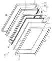
- FIG. 2 is an exploded perspective view schematically showing main parts constituting the liquid crystal television receiver in the first embodiment.
- FIG. 3 is a cross-sectional view taken along line AA in FIG. 2.
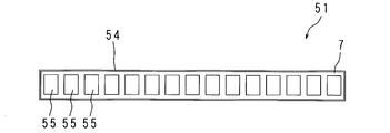
- FIG. 3 is a schematic diagram schematically showing a main part configuration of a light source unit of the liquid crystal television receiver according to the first embodiment.
- FIG. 2 is a longitudinal sectional view partially showing a configuration of a liquid crystal television receiver in the first embodiment.
- 6 is a longitudinal sectional view partially showing a configuration of a liquid crystal television receiver according to Embodiment 2.
- FIG. 10 is a longitudinal sectional view partially showing a configuration of a liquid crystal television receiver in Embodiment 3.
- FIG. 10 is a longitudinal sectional view partially showing a configuration of a liquid crystal television receiver in Embodiment 3.
- FIG. 1 is a front view showing an appearance of a liquid crystal television receiver 100 according to the first embodiment.
- the liquid crystal display panel 1 and other components are accommodated in a bezel 2 and a backlight chassis 6 described later.
- FIG. 2 is an exploded perspective view schematically showing a main part constituting the liquid crystal television receiver 100 according to Embodiment 1
- FIG. 3 is a cross-sectional view taken along the line AA of FIG.
- the liquid crystal television receiver 100 includes a rectangular liquid crystal display panel 1 on the front side, and the liquid crystal display panel 1 displays an image on one surface of the front side. Further, on the back side of the liquid crystal display panel 1, an optical sheet 3, a holding frame member 4, a light source device 5, and a backlight chassis 6 are provided in this order.
- the light source device 5 includes a light source unit 51, a light guide plate 52, and a reflection sheet 53.
- a direction along the longitudinal direction of the liquid crystal display panel 1 is referred to as a device left-right direction
- a direction along the thickness direction of the liquid crystal display panel 1 is also referred to as a back-and-front direction.
- the optical sheet 3 is disposed so that the front surface faces the back surface of the liquid crystal display panel 1, and the light guide plate 52 is disposed so that the light emitting surface that emits light faces the back surface of the optical sheet 3, and further reflects.
- the sheet 53 is disposed so that the front surface faces the back surface of the light guide plate 52 facing the light exit surface.
- the bezel 2 is a rectangular frame.
- the bezel 2 includes a rectangular cylindrical side plate and a frame portion 21 of an annular plate projecting inwardly from one end of the front side of the side plate, and the cross-sectional shape in the back and front direction is L-shaped.
- a frame portion 21 of the bezel 2 is disposed on the front side from the liquid crystal display panel 1. In other words, in the liquid crystal display panel 1, the peripheral edge portion of the one surface is covered with the frame portion 21 of the bezel 2. The user can visually recognize an image displayed on the one surface of the liquid crystal display panel 1 through the frame portion 21.
- the liquid crystal display panel 1 is a display panel and has a rectangular flat plate shape.
- the liquid crystal display panel 1 employs an active matrix method. Further, the liquid crystal display panel 1 is provided with polarizing plates (not shown) on the one surface and the back surface.
- the liquid crystal display panel 1 may be an electrophoretic liquid crystal panel, for example.
- the optical sheet 3 provided on the back side of the liquid crystal display panel 1 diffuses and collects light that is emitted from the light source unit 51 and incident through the light guide plate 52, thereby providing more uniform light.
- This is a known device that emits light toward the liquid crystal display panel 1.
- the optical sheet 3 includes three unit sheets 31, 32, and 33 that are overlapped. More specifically, the optical sheet 3 includes two diffusion sheets 31 and 33 and one prism sheet 32, and the prism sheet 32 is interposed between the two diffusion sheets 31 and 33.
- the diffusion sheet 31, the prism sheet 32, and the diffusion sheet 33 are the same rectangle and have the same size.
- the diffusion sheet 31 disposed on the light guide plate 52 side of the two diffusion sheets 31 and 33 is an optical sheet that diffuses the light incident from the light source unit 51 through the light guide plate 52 and enters the prism sheet 32. is there.
- the prism sheet 32 is an optical sheet that collects light incident through the diffusion sheet 31 and passes the light toward the diffusion sheet 33. The light that has passed through the prism sheet 32 is incident on the diffusion sheet 33 perpendicular to the prism sheet 32.
- the diffusion sheet 33 disposed on the liquid crystal display panel 1 side further diffuses the light incident through the prism sheet 32 to have a more uniform luminance distribution and pass it toward the back surface of the liquid crystal display panel 1. It is.
- the diffusion sheets 31 and 33 and the prism sheet 32 are collectively referred to as an optical sheet 3.
- the holding frame member 4 is a hollow rectangular frame surrounding the side surfaces of the liquid crystal display panel 1 and the optical sheet 3.
- the holding frame member 4 surrounds the side wall of the liquid crystal display panel 1 and the end of the optical sheet 3, and protrudes from the surrounding wall 41 toward the liquid crystal display panel 1 or the optical sheet 3, and has a step at the tip. And a protrusion 42 having the same.
- the holding frame member 4 is perpendicular to the first facing surface 43 and the first facing surface 43 facing the side surface of the liquid crystal display panel 1 in the surrounding wall 41, and receives the liquid crystal display panel 1.
- the panel receiving portion 44 is a surface forming a step between the projecting portion 42 and a second facing surface 45 facing the end of the optical sheet 3, and is perpendicular to the second facing surface 45.
- the panel receiving portion 44 has a rectangular ring shape
- the sheet receiving portion 46 has a rectangular ring shape smaller than the rectangle formed by the panel receiving portion 44. Accordingly, the panel receiving portion 44 supports the peripheral edge of the back surface of the liquid crystal display panel 1, and the liquid crystal display panel 1 is held so as to cover the hollow portion related to the panel receiving portion 44. Further, the sheet receiving portion 46 supports the peripheral edge portion of the back surface of the optical sheet 3, and the optical sheet 3 is held so as to cover the hollow portion related to the sheet receiving portion 46.
- the light source device 5 is housed in a backlight chassis 6 having a rectangular parallelepiped box shape with one side open.
- the backlight chassis 6 includes a bottom 62 (opposite plate portion) disposed to face the back surface of the reflection sheet 53 and a cylindrical side wall 61 extending in a direction orthogonal to the edge of the bottom 62. Yes.
- the surrounding wall 41 of the holding frame member 4 and the side wall 61 of the backlight chassis 6 are surrounded by the bezel 2.
- a light source 51 is provided inside the side wall 61 of the backlight chassis 6.
- the light source unit 51 includes a substrate 54 and a plurality of light emitting diodes (LEDs: Light ⁇ Emitting Diode) 55 mounted on a light emitting diode mounting surface 541 described later of the substrate 54.
- LEDs Light ⁇ Emitting Diode
- the substrate 54 has a strip shape whose longitudinal direction is the left-right direction, and the back surface corresponding to the light emitting diode mounting surface 541 is in contact with the side wall 61 of the backlight chassis 6.
- the dimension in the longitudinal direction of the substrate 54 is approximately equal to the dimension in the longitudinal direction of the light guide plate 52, and the dimension in the short direction of the substrate 54 is approximately equal to the thickness of the light guide plate 52.
- FIG. 4 is a schematic diagram schematically showing a main configuration of the light source unit 51 of the liquid crystal television receiver 100 according to the first embodiment
- FIG. 5 is a configuration of the liquid crystal television receiver 100 according to the first embodiment. It is a longitudinal cross-sectional view which shows partially. In FIG. 5, the display of the reflection sheet 53 is omitted for convenience of explanation.
- the light emitting diode mounting surface 541 faces one side 521 of the light guide plate 52 in the vicinity of the light emitting diode 55.
- a plurality of light emitting diodes 55 are mounted on the light emitting diode mounting surface 541.
- the plurality of light emitting diodes 55 are arranged in parallel at equal intervals along the longitudinal direction of the substrate 54.
- the light-emitting diode mounting surface 541 is provided with a preventing member 7 for preventing the light guide plate 52 and the light-emitting diode 55 from contacting each other.
- the prevention member 7 includes between the light emitting diodes 55 and is on the light emitting diode mounting surface 541 and excludes the light emitting diodes 55, 55,... 55, that is, a portion excluding the occupied portion by the light emitting diodes 55, 55,. Is provided.
- the prevention member 7 has a bag and a dilatant fluid filled in the bag.
- the bag body is configured to be deformed according to the behavior of the dilatant fluid.
- the prevention member 7 has a predetermined shape, but is configured to be deformed according to the behavior of the dilatant fluid.
- the dilatant fluid is a fluid that has the property of acting like a liquid in a small shear stress and acting like a solid in a large shear stress (hereinafter referred to as solidification). That is, the dilatant fluid is a fluid that exhibits fluidity with respect to a slow external pressure and has a characteristic of acting in a solid state with a slight volume reduction with respect to a sudden external pressure. Such solidification of the dilatant fluid is performed instantaneously. In addition, the dilatant fluid regains fluidity in a situation where such external pressure is removed.
- the prevention member 7 is interposed between the substrate 54 and the light guide plate 52, and the dimension of the prevention member 7 is larger than the dimension of the light emitting diode 55 in the thickness direction of the substrate 54.
- the prevention member 7 is in contact with one side 521 of the light guide plate 52 at the tip. Therefore, the contact between the light emitting diodes 55, 55,... 55 and the one side surface 521 of the light guide plate 52 is prevented by the prevention member 7.
- a rectangular light guide plate 52 is disposed on the back side of the optical sheet 3. That is, the light exit surface of the light guide plate 52 is disposed to face the back surface of the optical sheet 3.
- the light guide plate 52 is held at the edge of the protruding portion 42 of the holding frame member 4 with the cushion C interposed therebetween. In other words, the edge portion of the light guide plate 52 is covered with the protruding portion 42.
- the light guide plate 52 is emitted from the light source unit 51, diffuses the light received from the side surface 521, and emits the light toward the optical sheet 3 from the light output surface.
- the light guide plate 52 is made of, for example, a transparent plate material (glass, acrylic resin, polycarbonate resin, or the like).
- a point light source such as an LED
- the light guide plate 52 diffuses light from each point light source and uniformly emits it from the light exit surface as surface emission.
- the reflection sheet 53 is, for example, rectangular, and is disposed so that the surface thereof faces the back surface of the light guide plate 52, and returns light emitted from the back surface of the light guide plate 52 to the light guide plate 52. Further, as described above, the light source unit 51 is provided on one side 521 side of the light guide plate 52.
- the liquid crystal television receiver 100 according to Embodiment 1 having such a configuration can prevent the light guide plate 52 from colliding with the light-emitting diodes 55, 55,... 55 when an impact is applied from the outside of the device. .
- a side impact when an impact is applied from the side surface of the liquid crystal television receiver 100 (hereinafter simply referred to as a side impact), the light guide plate 52 is pressed against the light emitting diodes 55, 55,. Will shift. This may cause the light guide plate 52 and the light emitting diodes 55, 55,... 55 to collide, but the liquid crystal television receiver 100 according to the first embodiment can solve such a problem. This will be described in detail below.
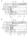
- FIG. 5A shows a case where a side impact is not applied to the liquid crystal television receiver 100 according to Embodiment 1
- FIG. 5B is a case where a side impact is applied to the liquid crystal television receiver 100 according to Embodiment 1.
- action of the prevention member 7 in the case of a case is shown.
- the light guide plate 52 When the liquid crystal television receiver 100 receives the side impact, the light guide plate 52 is suddenly shifted toward the light emitting diodes 55, 55,... 55. A sudden external pressure is applied. In addition, the dilatant fluid is instantly solidified against such a sudden external pressure. As the dilatant fluid is reduced in volume to some extent, the light guide plate 52 is slightly shifted (see the arrow in FIG. 5B), but after the dilatant fluid is solidified, further shift of the light guide plate 52 is prevented from solidifying. Blocked by member 7. Therefore, even when the side impact occurs, the collision between the one side 521 of the light guide plate 52 and the liquid crystal television receiver 100 is prevented.
- the liquid crystal television receiver 100 is not subjected to the side impact, for example, when the light guide plate 52 expands due to thermal expansion, external pressure is applied to the prevention member 7, but sudden external pressure is applied. It is not to join. Accordingly, the dilatant fluid behaves like a liquid, and the prevention member 7 is deformed in response to the expansion of the light guide plate 52.
- the prevention member 7 is provided on all portions except the light emitting diodes 55, 55,... 55 on the light emitting diode mounting surface 541. Yes. Therefore, a certain effect can be obtained as compared with the case where the prevention member 7 is locally provided at several locations on the light emitting diode mounting surface 541.
- the prevention member 7 is provided on all portions except the light emitting diodes 55, 55,... 55 on the light emitting diode mounting surface 541, a cooling effect for absorbing heat generated from the light emitting diodes 55, 55,. Play.
- FIG. 6 is a longitudinal sectional view partially showing a configuration of the liquid crystal television receiver 100 according to the second embodiment.
- the display of the reflection sheet 53 is omitted for convenience of explanation.
- the prevention member 7 is provided between the light guide plate 52 and the bottom 62 of the backlight chassis 6. More specifically, the prevention member 7 is provided between an edge (hereinafter referred to as a light source side edge) of the light guide plate 52 according to one side 521 and the bottom 62. Moreover, the prevention member 7 has a bag body and the dilatant fluid with which the bag body was filled similarly to Embodiment 1.
- FIG. 1 A light source side edge
- the prevention member 7 has a strip shape in which the direction along the longitudinal direction of the one side surface 521 is the longitudinal direction, and one end portion on the light source 51 side protrudes from the one side surface 521 of the light guide plate 52 in the lateral direction. ing.
- the liquid crystal television receiver 100 includes a guide member 8 that guides the deformation of the prevention member 7.
- the guide member 8 is provided between the light source 51 and the bottom 62 of the backlight chassis 6 in the front-back direction.
- the guide member 8 is provided along the light source 51 on the light source 51 side from the one end of the prevention member 7.
- the guide member 8 has a concave curved surface on the prevention member 7 side.
- the light guide plate 52 when the side impact is applied to the liquid crystal television receiver 100, the light guide plate 52 is pressed toward the light emitting diodes 55, 55,... 55 side, and shifts in the direction along the surface. There is a possibility that the diodes 55, 55,. However, in the liquid crystal television receiver 100 according to Embodiment 2 having the above-described configuration, the light guide plate 52 collides with the light-emitting diodes 55, 55,... 55 even when the side impact is applied. It can be prevented beforehand. This will be described in detail below.
- FIG. 6A shows a case where a side impact is not applied to the liquid crystal television receiver 100 according to Embodiment 2
- FIG. 6B is a case where a side impact is applied to the liquid crystal television receiver 100 according to Embodiment 2.
- the action of the prevention member 7 and the guide member 8 in the case of failure is shown.
- the preventing member 7 When the liquid crystal television receiver 100 is subjected to the side impact, the preventing member 7 is deformed by receiving a force to be pressed against the light source 51 side. Specifically, during such a side impact, the dilatant fluid of the prevention member 7 still behaves as a liquid, so that the dilatant fluid moves instantaneously by such force. At this time, the movement of the dilatant fluid is guided by the guide member 8. That is, the dilatant fluid is guided by the curved surface of the guide member 8 and moves between the substrate 54 and the light guide plate 52 (one side surface 521), and the prevention member 7 is deformed accordingly (in FIG. 6A, (See dotted arrow).
- the light guide plate 52 is suddenly shifted toward the light-emitting diodes 55, 55,... 55 by the side impact, but the gap between the substrate 54 and the light guide plate 52 (one side surface 521) is already as described above.
- the prevention member 7 is present. Accordingly, the prevention member 7 is suddenly subjected to external pressure by the light guide plate 52, and the dilatant fluid is instantly solidified in accordance with such sudden external pressure. As the dilatant fluid is reduced in volume to some extent, the light-emitting diodes 55, 55,... 55 are slightly shifted, but after the dilatant fluid is solidified, the light guide plate 52 is further shifted by the solidified prevention member 7. Be blocked. Therefore, even when there is an impact from the outside, the collision between the one side surface 521 of the light guide plate 52 and the light emitting diodes 55, 55,.
- the prevention member 7 is provided between the light source side edge of the light guide plate 52 and the bottom 62. Therefore, even when an impact is applied from the outside to the front and back in the liquid crystal television receiver 100, the light guide plate 52 and the bottom 62 of the backlight chassis 6 are fixed by changing the prevention member 7 and fixing the dilatant fluid. Can be prevented from colliding.
- the guide member 8 is further provided has been described as an example.
- the liquid crystal television receiver 100 according to Embodiment 2 is not limited to this, and the guide member 8 is omitted. Also good.
- FIG. 7 is a longitudinal sectional view partially showing the configuration of the liquid crystal television receiver 100 according to the third embodiment.
- the display of the reflection sheet 53 is omitted for convenience of explanation.
- the prevention member 7 is provided between the light source side edge of the light guide plate 52 and the bottom 62. Moreover, the prevention member 7 has a bag body and the dilatant fluid with which the bag body was filled similarly to Embodiment 1.
- FIG. The structure of the other prevention member 7 is the same as that of Embodiment 2, and detailed description is abbreviate
- the liquid crystal television receiver 100 according to Embodiment 3 includes a guide member 8 having a curved surface on the prevention member 7 side.
- the structure of the guide member 8 is the same as that of Embodiment 2, and detailed description is abbreviate
- an inclined portion 63 that guides the deformation of the prevention member 7 is formed on the bottom 62 along the light source 51. More specifically, the inclined portion 63 is inclined in a direction away from the light source 51 at a portion corresponding to the light source 51 in the front and back direction on the bottom 62. Further, the inclined portion 63 is formed from the side of the light source 51 side of the prevention member 7 to the side wall 61 of the backlight chassis 6, and is inclined so as to be farther from the light source 51 as it is closer to the side wall 61 of the backlight chassis 6. Has been.
- the liquid crystal television receiver 100 when the side impact is applied to the liquid crystal television receiver 100, the light guide plate 52 is pressed toward the light emitting diodes 55, 55,... 55 side, and shifts in the direction along the surface. There is a possibility that the diodes 55, 55,.
- the liquid crystal television receiver 100 according to Embodiment 3 having the above-described configuration can prevent the light guide plate 52 from colliding with the light emitting diodes 55, 55,... 55 when the side impact is applied. . This will be described in detail below.
- FIG. 7A shows a case where a side impact is not applied to the liquid crystal television receiver 100 according to the third embodiment.
- FIG. 7B a side impact is applied to the liquid crystal television receiver 100 according to the third embodiment.
- action of the prevention member 7, the guide member 8, and the inclination part 63 in the case of adding is shown.
- the preventing member 7 When the liquid crystal television receiver 100 is subjected to the side impact, the preventing member 7 is deformed by receiving a force to be pressed against the light source 51 side. Specifically, during such a side impact, the dilatant fluid of the prevention member 7 still behaves as a liquid, so that the dilatant fluid moves instantaneously by such force. At this time, the movement of the dilatant fluid is guided by the guide member 8 and the inclined portion 63.
- the dilatant fluid moves to the guide member 8 along the inclined portion 63 when moving. Thereafter, the dilatant fluid is guided by the curved surface of the guide member 8 and moves between the substrate 54 and the light guide plate 52 (one side surface 521), and the prevention member 7 is deformed accordingly (the dotted line in FIG. 7A). See arrow).
- the light guide plate 52 is suddenly shifted toward the light-emitting diodes 55, 55,... 55 by the side impact, but the gap between the substrate 54 and the light guide plate 52 (one side surface 521) is already as described above.
- the prevention member 7 is present. Accordingly, the prevention member 7 is suddenly subjected to external pressure by the light guide plate 52, and the dilatant fluid is instantly solidified in accordance with such sudden external pressure. As the dilatant fluid is reduced in volume to some extent, the light guide plate 52 is slightly shifted, but after the dilatant fluid is solidified, the further shift of the light guide plate 52 is blocked by the solidified preventing member 7. Therefore, even when there is a side impact, collision between one side 521 of the light guide plate 52 and the light emitting diodes 55, 55,... 55 can be prevented.
- the prevention member 7 when an impact is applied from the outside to the front and back sides, the prevention member 7 is changed and the dilatant fluid is fixed. It is possible to prevent the light guide plate 52 and the bottom 62 of the backlight chassis 6 from colliding with each other.
- the liquid crystal television receiver 100 when there is an impact from the outside while keeping the distance between the light emitting diodes 55, 55,... 55 and the light guide plate 52 narrow, It is possible to reliably prevent a collision between one side surface 521 of the light guide plate 52 and the light emitting diodes 55, 55,.
Landscapes
- Engineering & Computer Science (AREA)
- General Engineering & Computer Science (AREA)
- Planar Illumination Modules (AREA)
- Liquid Crystal (AREA)
Abstract
光源と、該光源からの光を一側面にて受光し、該一側面と交差する出光面から放出する導光板と、該導光板及び前記光源の接触を防止する防止部材とを備える光源装置において、前記防止部材はダイラタント流体を含むので、例えば、前記光源装置が外部から衝撃を受け、前記導光板のシフトが生じた場合、前記ダイラタント流体が固体して前記導光板と前記光源との衝突を未然に防止する。
Description
本発明は、光源と、該光源からの光を一側面にて受光し、該一側面と交差する一面から放出する導光板と、該導光板及び前記光源の接触を防止する防止部材とを備える光源装置、及び、該光源装置を備える表示装置に関する。
画像が表示される液晶パネルと、光源と、該光源が発する光を前記液晶パネル側に放出する導光板とを有する、いわゆるエッジ型光源装置を備えた表示装置が広く普及されている。
例えば、特許文献1においては、導光板の一側面に沿って複数のLEDを設け、導光板の前記一側面に、突出寸法が等しい複数の凸部を形成し、各凸部の先端面をLEDの実装基板に当接させることにより、各LEDと導光板の前記一側面との間にクリアランスが保たれる液晶モジュールが開示されている。
一方、斯かる表示装置が外部から衝撃を受けた場合、該衝撃で前記導光板がシフトして光源(例えば、LED)と衝突する虞がある。これに対して特許文献1の液晶モジュールにおいては、当該導光板の一側面に形成された凸部により、光源との衝突を防止できる。しかしながら、特許文献1の液晶モジュールでは、凸部を形成する必要があって製造コストが高まり、幾つかの凸部によって導光板全体の荷重を支えるので凸部破損の虞があるうえ、導光板(凸部)によって常に基板側に圧力がかかり、導光板の熱膨張には斯かる基板が破損する恐れもある。
本発明は、斯かる事情に鑑みてなされたものであり、その目的とするところは、光源と、該光源からの光を一側面にて受光し、該一側面と交差する出光面から放出する導光板と、該導光板及び前記光源の接触を防止する防止部材とを備える光源装置において、外部から衝撃を受けた場合であっても、前記導光板が前記光源と衝突することを防止できる光源装置、並びに、該光源装置を備える表示装置を提供することにある。
本発明に係る光源装置は、光源と、該光源からの光を一側面にて受光し、該一側面と交差する出光面から放出する導光板と、該導光板及び前記光源の接触を防止する防止部材とを備える光源装置において、前記防止部材はダイラタント流体を含むことを特徴とする。
本発明にあっては、前記防止部材はダイラタント流体を含むので、例えば、前記光源装置が外部から衝撃を受け、前記導光板のシフトが生じた場合、前記ダイラタント流体が固体化して前記導光板と前記光源との衝突を未然に防止する。
本発明に係る表示装置は、前述の発明の光源装置と、前記光源装置からの光を用いて、画像を表示する表示パネルとを備えることを特徴とする。
本発明にあっては、前記表示パネルは前記光源装置から発せられる光を用いて、その一面に画像を表示する。
本発明によれば、外部から衝撃を受けた場合であっても、前記導光板が前記光源と衝突することを未然に防止できる。
以下に、本発明の実施の形態に係る光源装置及び表示装置を、液晶パネルを備えるいわゆる液晶テレビジョン受像機に適用した場合を例として、図面に基づいて詳述する。
(実施の形態1)
図1は、実施の形態1における液晶テレビジョン受像機100の外観を示す正面図である。液晶テレビジョン受像機100おいて、液晶表示パネル1及び他の部品は、ベゼル2及び後述するバックライトシャーシ6に収納されている。
図1は、実施の形態1における液晶テレビジョン受像機100の外観を示す正面図である。液晶テレビジョン受像機100おいて、液晶表示パネル1及び他の部品は、ベゼル2及び後述するバックライトシャーシ6に収納されている。
図2は、実施の形態1における液晶テレビジョン受像機100を構成する要部を模式的に示す分解斜視図であり、図3は、図2のA-A線による断面図である。
本実施の形態に係る液晶テレビジョン受像機100は、図1に示したように、表側に矩形の液晶表示パネル1を備えており、液晶表示パネル1は表側の一面に映像を表示する。また、液晶表示パネル1の裏側には光学シート3と、保持枠部材4と、光源装置5と、バックライトシャーシ6とが斯かる順に設けられている。また、光源装置5は光源部51、導光板52及び反射シート53を有している。以下においては、説明の便宜上、液晶表示パネル1の長手方向に沿う方向を機器左右方向と言い、液晶表示パネル1の厚み方向に沿う方向を裏表方向とも言う。
光学シート3は表面が液晶表示パネル1の裏面と対向するように配置されており、また、導光板52は光を放出する出光面が光学シート3の裏面と対向するように配置され、更に反射シート53は表面が導光板52の出光面と対向する裏面と対向するように配置されている。
ベゼル2は、矩形状の枠体である。ベゼル2は、矩形の筒状の側板と、該側板の表側一端部から内向きに張り出した環状板の額縁部21とからなり、前記裏表方向での断面形状はL字状をなす。液晶表示パネル1より表側には、ベゼル2の額縁部21が配置されている。換言すれば、液晶表示パネル1は、前記一面の周縁部がベゼル2の額縁部21によって覆われている。ユーザは額縁部21を介して液晶表示パネル1の前記一面に表示される画像を視認することができる。
液晶表示パネル1は、表示パネルであり、矩形の平板状をなす。液晶表示パネル1は、アクティブマトリクス方式を採用している。また、液晶表示パネル1は前記一面及び前記裏面に偏光板(図示せず)を設けている。液晶表示パネル1は、例えば電気泳動液晶パネルであっても良い。
液晶表示パネル1の前記裏面側に設けられた光学シート3は、光源部51から発せられ、導光板52を介して入射される光に対して拡散、集光等を行ない、より均一な光を液晶表示パネル1に向けて出射させる、公知のものである。例えば、光学シート3は、重ね合わせた3枚の単位シート31,32,33を有する。より詳しくは、光学シート3は2枚の拡散シート31,33と、1枚のプリズムシート32とを含み、プリズムシート32は2枚の拡散シート31,33の間に介在している。拡散シート31、プリズムシート32及び拡散シート33は同じ矩形であり、同一の大きさを有している。
2枚の拡散シート31,33のうち導光板52側に配置された拡散シート31は、導光板52を介して光源部51から入射される光を拡散させてプリズムシート32に入射させる光学シートである。また、プリズムシート32は、拡散シート31を介して入射される光を集光して拡散シート33に向けて通過させる光学シートである。プリズムシート32を通過した光は、プリズムシート32に対して垂直に拡散シート33へ入射される。
液晶表示パネル1側に配置された拡散シート33は、プリズムシート32を介して入射される光を更に拡散させてより均一な輝度分布にして液晶表示パネル1の前記裏面に向けて通過させる光学シートである。以下においては、説明の便宜上、拡散シート31,33と、プリズムシート32とをまとめて光学シート3とも言う。
保持枠部材4は、液晶表示パネル1及び光学シート3の側面を取り囲む中空矩形の枠体である。保持枠部材4は、液晶表示パネル1の側面及び光学シート3の端部を囲繞する囲繞壁41と、囲繞壁41から液晶表示パネル1又は光学シート3側に突設され、先端部に段差を有する突出部42とを有する。
より詳しくは、保持枠部材4は、囲繞壁41において液晶表示パネル1の側面と対向する第1対向面43と、第1対向面43に対して垂直をなしており、液晶表示パネル1を受けるパネル受け部44と、突出部42の段差をなす面であって光学シート3の端部と対向する第2対向面45と、第2対向面45に対して垂直をなしており、光学シート3を受けるシート受け部46とを有している。
換言すれば、前記裏表方向において、パネル受け部44は矩形の環状をなし、シート受け部46はパネル受け部44による矩形より小さい矩形の環状をなす。従って、パネル受け部44は液晶表示パネル1の前記裏面の周縁部を支持しており、液晶表示パネル1はパネル受け部44に係る中空部を覆うように保持される。また、シート受け部46は光学シート3の前記裏面の周縁部を支持しており、光学シート3はシート受け部46に係る中空部を覆うように保持される。
光源装置5は、一面が開放された直方体の箱状をなすバックライトシャーシ6に収納されている。バックライトシャーシ6は、反射シート53の裏面と対向して配置された底62(対向板部)と、底62の縁から直交する方向に延設された筒状の側壁61とを有している。保持枠部材4の囲繞壁41及びバックライトシャーシ6の側壁61はベゼル2によって取り囲まれている。
バックライトシャーシ6の側壁61の内側には、光源部51が設けられている。光源部51は基板54と、基板54の後述する発光ダイオード実装面541の上に実装された複数の発光ダイオード(LED:Light Emitting Diode)55とを有する。
基板54は前記左右方向を長手方向とする短冊状をなしており、発光ダイオード実装面541に対応する裏面はバックライトシャーシ6の側壁61と当接している。基板54の長手方向の寸法は導光板52の長手方向の寸法と略等しく、基板54の短手方向の寸法は導光板52の厚みと略等しい。
図4は実施の形態1に係る液晶テレビジョン受像機100の光源部51の要部構成を模式的に示す模式図であり、図5は、実施の形態1における液晶テレビジョン受像機100の構成を部分的に示す縦断面図である。図5においては、説明の便宜上、反射シート53の表示を省略している。
発光ダイオード実装面541は、発光ダイオード55近傍の導光板52の一側面521と対向している。発光ダイオード実装面541には、複数の発光ダイオード55が実装されている。複数の発光ダイオード55は、基板54の長手方向に沿って、等間隔にて並設されている。
また、発光ダイオード実装面541には、導光板52及び発光ダイオード55の接触を防止する防止部材7が設けられている。防止部材7は、発光ダイオード55同士間を含み、発光ダイオード実装面541上であって発光ダイオード55,55,…55を除く部分、すなわち、発光ダイオード55,55,…55による占有部を除く部分に設けられている。
防止部材7は、袋体と、該袋体内に充填されたダイラタント流体とを有する。前記袋体はダイラタント流体の振る舞いに応じて変形されるように構成されている。換言すれば、防止部材7は、所定の形状をなしているものの、斯かるダイラタント流体の振る舞いに応じて変形するように構成されている。
ここで、ダイラタント流体とは、小さい剪断応力には液体のように振る舞い、大きい剪断応力には固体のように振る舞う(以下、固体化と言う)性質を有する流体である。すなわち、ダイラタント流体は、ゆっくりとした外部圧力に対しては流動性を示し、急激な外部圧力に対してはわずかな体積減少はあるものの固体的に作用する特性を有する流体である。なお、ダイラタント流体の斯かる固体化は瞬時に行われる。また、ダイラタント流体は、斯かる外部圧力が除去された状況においては、流動性を取り戻す。
このように、防止部材7は、基板54及び導光板52の間に介在しており、基板54の厚み方向において、防止部材7の寸法は、発光ダイオード55の寸法より大きい。また、防止部材7は先端が導光板52の一側面521と当接している。従って、防止部材7によって、発光ダイオード55,55,…55と導光板52の一側面521との当接を未然に防止する。
一方、光学シート3の裏面側には矩形の導光板52が配置されている。すなわち、導光板52の前記出光面は光学シート3の前記裏面と対向して配置されている。導光板52はクッションCを挟んで保持枠部材4の突出部42の縁部に保持されている。換言すれば、導光板52の縁部は、突出部42によって覆われている。導光板52は光源部51から出射され、側面521から受光した光を拡散させて前記出光面から光学シート3に向けて放出する。
導光板52は、例えば、透明の板材(ガラス、アクリル樹脂、ポリカーボネート樹脂等)からなる。光源としてLEDのような点光源を使用した場合、導光板52は各点光源からの光を拡散させて均一に面発光として前記出光面から放出する。
反射シート53は、例えば、矩形であり、その表面が導光板52の裏面と対向するように配置され、導光板52の前記裏面から放出される光を導光板52に戻す。また、導光板52の一側面521側には、上述したように光源部51が設けられている。
このような構成を有する実施の形態1に係る液晶テレビジョン受像機100は、機器外部から衝撃が加わった場合、導光板52が発光ダイオード55,55,…55と衝突することを未然に防止できる。例えば、液晶テレビジョン受像機100の側面から衝撃が加わった場合(以下、単に側面衝撃と言う。)、導光板52は発光ダイオード55,55,…55側に押し付けられ、その面に沿う方向に、シフトすることとなる。これにより、導光板52と発光ダイオード55,55,…55とが衝突する虞が生じるが、実施の形態1に係る液晶テレビジョン受像機100においては、このような問題を解決できる。以下、詳しく説明する。
図5Aは、実施の形態1に係る液晶テレビジョン受像機100に側面衝撃が加わっていない場合を示しており、図5Bは、実施の形態1に係る液晶テレビジョン受像機100に側面衝撃が加わった場合における、防止部材7の作用を示している。
液晶テレビジョン受像機100が前記側面衝撃を受けた場合、導光板52は発光ダイオード55,55,…55に向けて、急にシフトされるので、導光板52と当接している防止部材7には急激は外部圧力が加わる。また、斯かる急激な外部圧力に対して、ダイラタント流体は瞬時固体化される。ダイラタント流体がある程度体積減少することに伴い、導光板52のシフトが少し生じるものの(図5B中、矢印参照)、ダイラタント流体の固体化後は、それ以上の導光板52のシフトは固体化した防止部材7により阻止される。従って、前記側面衝撃があった場合においても、導光板52の一側面521と液晶テレビジョン受像機100との衝突が防止される。
一方、液晶テレビジョン受像機100が前記側面衝撃を受けていない通常の場合において、例えば、熱膨張により導光板52が膨張するときは、防止部材7に外部圧力が加わるが、急激な外部圧力が加わることではない。従って、ダイラタント流体は液体のように振る舞い、防止部材7は導光板52の膨張に応じて変形する。
以上のことから、実施の形態1に係る液晶テレビジョン受像機100においては、発光ダイオード55,55,…55及び導光板52間の間隔を狭く維持しつつ、前記側面衝撃があった場合において、導光板52の一側面521と発光ダイオード55,55,…55との衝突を確実に防止できる。
また、実施の形態1に係る液晶テレビジョン受像機100においては、上述したように、防止部材7が発光ダイオード実装面541上において発光ダイオード55,55,…55を除く全ての部分に設けられている。従って、発光ダイオード実装面541上の幾つかの箇所に防止部材7を局所的に設けた場合に比べ、確実な効果を得ることが出来る。
更に、防止部材7が発光ダイオード実装面541上において発光ダイオード55,55,…55を除く全ての部分に設けられているので、発光ダイオード55,55,…55から発する熱を吸収する冷却効果を奏する。
(実施の形態2)
図6は、実施の形態2における液晶テレビジョン受像機100の構成を部分的に示す縦断面図である。図6においては、説明の便宜上、反射シート53の表示を省略している。
図6は、実施の形態2における液晶テレビジョン受像機100の構成を部分的に示す縦断面図である。図6においては、説明の便宜上、反射シート53の表示を省略している。
実施の形態2に係る液晶テレビジョン受像機100において、防止部材7は、導光板52とバックライトシャーシ6の底62との間に設けられている。より詳しくは、防止部材7は、一側面521に係る導光板52の縁部(以下、光源側縁部と言う)と底62との間に設けられている。また、防止部材7は、実施の形態1と同様に、袋体と、該袋体内に充填されたダイラタント流体とを有する。
防止部材7は、例えば、一側面521の長手方向に沿う方向を長手方向とする短冊状をなしており、短手方向においては、光源51側の一端部が導光板52の一側面521からはみ出ている。
更に、実施の形態2に係る液晶テレビジョン受像機100は、防止部材7の変形を案内する案内部材8を備えている。案内部材8は前記裏表方向において、光源51と、バックライトシャーシ6の底62との間に、設けられている。換言すれば、案内部材8は、防止部材7の前記一端部より光源51側にて、光源51に沿って設けられている。また、案内部材8は、防止部材7側に凹状の湾曲面を有している。
例えば、液晶テレビジョン受像機100に前記側面衝撃が加わった場合、導光板52は発光ダイオード55,55,…55側に押し付けられ、その面に沿う方向に、シフトするので、導光板52と発光ダイオード55,55,…55とが衝突する虞が生じる。しかし、上述した構成を有する実施の形態2に係る液晶テレビジョン受像機100は、前記側面衝撃が加わった場合であっても、導光板52が発光ダイオード55,55,…55と衝突することを未然に防止できる。以下、詳しく説明する。
図6Aは、実施の形態2に係る液晶テレビジョン受像機100に側面衝撃が加わっていない場合を示しており、図6Bは、実施の形態2に係る液晶テレビジョン受像機100に側面衝撃が加わった場合における、防止部材7及び案内部材8の作用を示している。
液晶テレビジョン受像機100が前記側面衝撃を受けた場合、防止部材7は光源51側に押し付ける力を受けて変形する。詳しくは、斯かる側面衝撃のとき、防止部材7のダイラタント流体は未だ液体として振る舞うので、斯かる力により、ダイラタント流体が瞬時に移動する。この際、ダイラタント流体の移動は案内部材8によって、案内される。すなわち、案内部材8の前記湾曲面によって案内され、ダイラタント流体は、基板54と導光板52(一側面521)との間に移動し、これに応じて防止部材7は変形する(図6Aにおける、点線の矢印参照)。
前記側面衝撃によって、導光板52は発光ダイオード55,55,…55に向けて、急にシフトされるが、既に、基板54と導光板52(一側面521)と間には、上述したように、防止部材7が存在している。従って、防止部材7は導光板52によって急激は外部圧力を受け、斯かる急激な外部圧力に応じて、ダイラタント流体は瞬時固体化される。ダイラタント流体がある程度体積減少することに伴い、発光ダイオード55,55,…55のシフトが少し生じるものの、ダイラタント流体の固体化後は、それ以上の導光板52のシフトは固体化した防止部材7により阻止される。従って、外部から衝撃があった場合においても、導光板52の一側面521と発光ダイオード55,55,…55との衝突が防止される。
更に、実施の形態2に係る液晶テレビジョン受像機100においては、上述したように、防止部材7が導光板52の前記光源側縁部と底62との間に設けられている。従って、液晶テレビジョン受像機100にて、外部から前記裏表方向に衝撃が加わった場合においても、防止部材7の変更及びダイラタント流体の固定化により、導光板52とバックライトシャーシ6の底62とが衝突することを防止できる。
以上のことから、実施の形態2に係る液晶テレビジョン受像機100においては、発光ダイオード55,55,…55及び導光板52間の間隔を狭く維持しつつ、前記側面衝撃があった場合において、導光板52の一側面521と発光ダイオード55,55,…55との衝突を確実に防止できる。
なお、以上においては、案内部材8を更に備える場合を例として説明したが、実施の形態2に係る液晶テレビジョン受像機100はこれに限るものでなく、案内部材8を省略した構成であっても良い。
実施の形態1と同様の部分については、同一の符号を付して詳細な説明を省略する。
(実施の形態3)
図7は、実施の形態3における液晶テレビジョン受像機100の構成を部分的に示す縦断面図である。図7においては、説明の便宜上、反射シート53の表示を省略している。
図7は、実施の形態3における液晶テレビジョン受像機100の構成を部分的に示す縦断面図である。図7においては、説明の便宜上、反射シート53の表示を省略している。
実施の形態3に係る液晶テレビジョン受像機100において、防止部材7は、導光板52の前記光源側縁部と底62との間に設けられている。また、防止部材7は、実施の形態1と同様に、袋体と、該袋体内に充填されたダイラタント流体とを有する。他の防止部材7の構成は、実施の形態2と同様であり、詳しい説明を省略する。
また、実施の形態3に係る液晶テレビジョン受像機100は、防止部材7側に湾曲面を有する案内部材8を備えている。案内部材8の構成は、実施の形態2と同様であり、詳しい説明を省略する。
更に、実施の形態3に係る液晶テレビジョン受像機100では、防止部材7の変形を案内する傾斜部63が光源51に沿って底62に形成されている。より詳しくは、傾斜部63は、底62において、前記裏表方向における光源51に対応する部分にて、光源51から遠ざける方向に傾斜している。また、傾斜部63は、防止部材7の光源51側一端のすぐそばからバックライトシャーシ6の側壁61まで形成されており、バックライトシャーシ6の側壁61に近い程、光源51から遠ざけるように傾斜されている。
例えば、液晶テレビジョン受像機100に前記側面衝撃が加わった場合、導光板52は発光ダイオード55,55,…55側に押し付けられ、その面に沿う方向に、シフトするので、導光板52と発光ダイオード55,55,…55とが衝突する虞が生じる。しかし、上述した構成を有する実施の形態3に係る液晶テレビジョン受像機100は、前記側面衝撃が加わった場合、導光板52が発光ダイオード55,55,…55と衝突することを未然に防止できる。以下、詳しく説明する。
図7Aは、実施の形態3に係る液晶テレビジョン受像機100に側面衝撃が加わっていない場合を示しており、図7Bにおいては、実施の形態3に係る液晶テレビジョン受像機100に側面衝撃が加わった場合における、防止部材7、案内部材8及び傾斜部63の作用を示している。
液晶テレビジョン受像機100が前記側面衝撃を受けた場合、防止部材7は光源51側に押し付ける力を受けて変形する。詳しくは、斯かる側面衝撃のとき、防止部材7のダイラタント流体は未だ液体として振る舞うので、斯かる力により、ダイラタント流体が瞬時に移動する。この際、ダイラタント流体の移動は案内部材8及び傾斜部63によって、案内される。
すなわち、傾斜部63は防止部材7の光源51側一端に係る位置から形成されているので、ダイラタント流体は移動の際、傾斜部63に沿って案内部材8まで移動する。以降、ダイラタント流体は、案内部材8の前記湾曲面によって案内され、基板54と導光板52(一側面521)と間に移動し、これに応じて防止部材7は変形する(図7Aにおける、点線の矢印参照)。
前記側面衝撃によって、導光板52は発光ダイオード55,55,…55に向けて、急にシフトされるが、既に、基板54と導光板52(一側面521)と間には、上述したように、防止部材7が存在している。従って、防止部材7は導光板52によって急激は外部圧力を受け、斯かる急激な外部圧力に応じて、ダイラタント流体は瞬時固体化される。ダイラタント流体がある程度体積減少することに伴い、導光板52のシフトが少し生じるものの、ダイラタント流体の固体化後は、それ以上の導光板52のシフトは固体化した防止部材7により阻止される。従って、前記側面衝撃があった場合においても、導光板52の一側面521と発光ダイオード55,55,…55との衝突を防止できる。
更に、実施の形態3に係る液晶テレビジョン受像機100においても、実施の形態2と同様、外部から前記裏表方向に衝撃が加わった場合において、防止部材7の変更及びダイラタント流体の固定化により、導光板52とバックライトシャーシ6の底62とが衝突することを防止できる。
以上のことから、実施の形態3に係る液晶テレビジョン受像機100においては、発光ダイオード55,55,…55及び導光板52間の間隔を狭く維持しつつ、外部から衝撃があった場合において、導光板52の一側面521と発光ダイオード55,55,…55との衝突を確実に防止できる。
実施の形態1と同様の部分については、同一の符号を付して詳細な説明を省略する。
1 液晶表示パネル
6 バックライトシャーシ
7 防止部材
8 案内部材
51 光源
52 導光板
54 基板
55 発光ダイオード
62 底
63 傾斜部
100 液晶テレビジョン受像機
521 一側面
6 バックライトシャーシ
7 防止部材
8 案内部材
51 光源
52 導光板
54 基板
55 発光ダイオード
62 底
63 傾斜部
100 液晶テレビジョン受像機
521 一側面
Claims (6)
- 光源と、該光源からの光を一側面にて受光し、該一側面と交差する出光面から放出する導光板と、該導光板及び前記光源の接触を防止する防止部材とを備える光源装置において、
前記防止部材はダイラタント流体を含むことを特徴とする光源装置。 - 前記光源が一面に設けられた基板を備え、
前記防止部材は、前記基板の一面上であって前記光源を除く部分に設けられていることを特徴とする請求項1に記載の光源装置。 - 前記導光板の前記出光面と対向する裏面と対向して配置された対向板部を備え、
前記防止部材は、前記導光板の前記光源側縁部と前記対向板部との間に設けられていることを特徴とする請求項1に記載の光源装置。 - 前記光源及び前記対向板部の間に設けられ、前記防止部材の変形を案内する案内部材を備えることを特徴とする請求項3に記載の光源装置。
- 前記対向板部は、その厚み方向において前記光源に対応する部分が、前記光源から遠ざける方向に傾斜していることを特徴とする請求項3又は4に記載の光源装置。
- 請求項1から5の何れかに記載の光源装置と、
前記光源装置からの光を用いて、画像を表示する表示パネルと
を備えることを特徴とする表示装置。
Priority Applications (1)
| Application Number | Priority Date | Filing Date | Title |
|---|---|---|---|
| PCT/JP2016/055466 WO2017145294A1 (ja) | 2016-02-24 | 2016-02-24 | 光源装置及び表示装置 |
Applications Claiming Priority (1)
| Application Number | Priority Date | Filing Date | Title |
|---|---|---|---|
| PCT/JP2016/055466 WO2017145294A1 (ja) | 2016-02-24 | 2016-02-24 | 光源装置及び表示装置 |
Publications (1)
| Publication Number | Publication Date |
|---|---|
| WO2017145294A1 true WO2017145294A1 (ja) | 2017-08-31 |
Family
ID=59684902
Family Applications (1)
| Application Number | Title | Priority Date | Filing Date |
|---|---|---|---|
| PCT/JP2016/055466 Ceased WO2017145294A1 (ja) | 2016-02-24 | 2016-02-24 | 光源装置及び表示装置 |
Country Status (1)
| Country | Link |
|---|---|
| WO (1) | WO2017145294A1 (ja) |
Citations (6)
| Publication number | Priority date | Publication date | Assignee | Title |
|---|---|---|---|---|
| JP2011018508A (ja) * | 2009-07-08 | 2011-01-27 | Seiko Epson Corp | 電気光学装置および電子機器 |
| US20110267841A1 (en) * | 2010-04-29 | 2011-11-03 | Myung-Woon Lee | Display apparatus |
| JP2012237826A (ja) * | 2011-05-10 | 2012-12-06 | Funai Electric Co Ltd | 液晶モジュール |
| WO2013018648A1 (ja) * | 2011-08-03 | 2013-02-07 | シャープ株式会社 | 照明装置、表示装置、及びテレビ受信装置 |
| WO2013183597A1 (ja) * | 2012-06-05 | 2013-12-12 | Necカシオモバイルコミュニケーションズ株式会社 | 電子機器の表示部および当該表示部を有する携帯端末機器 |
| JP2015082370A (ja) * | 2013-10-22 | 2015-04-27 | トヨタ自動車株式会社 | 燃料電池 |
-
2016
- 2016-02-24 WO PCT/JP2016/055466 patent/WO2017145294A1/ja not_active Ceased
Patent Citations (6)
| Publication number | Priority date | Publication date | Assignee | Title |
|---|---|---|---|---|
| JP2011018508A (ja) * | 2009-07-08 | 2011-01-27 | Seiko Epson Corp | 電気光学装置および電子機器 |
| US20110267841A1 (en) * | 2010-04-29 | 2011-11-03 | Myung-Woon Lee | Display apparatus |
| JP2012237826A (ja) * | 2011-05-10 | 2012-12-06 | Funai Electric Co Ltd | 液晶モジュール |
| WO2013018648A1 (ja) * | 2011-08-03 | 2013-02-07 | シャープ株式会社 | 照明装置、表示装置、及びテレビ受信装置 |
| WO2013183597A1 (ja) * | 2012-06-05 | 2013-12-12 | Necカシオモバイルコミュニケーションズ株式会社 | 電子機器の表示部および当該表示部を有する携帯端末機器 |
| JP2015082370A (ja) * | 2013-10-22 | 2015-04-27 | トヨタ自動車株式会社 | 燃料電池 |
Similar Documents
| Publication | Publication Date | Title |
|---|---|---|
| JP5564345B2 (ja) | 表示装置 | |
| US10168574B2 (en) | Light source device and display apparatus | |
| US8899818B2 (en) | Backlight unit including light guide and gap retainer | |
| JP6441488B2 (ja) | 表示装置 | |
| CN108205224B (zh) | 背光及显示装置 | |
| TWI440941B (zh) | 背光模組 | |
| JP5878976B2 (ja) | バックライトユニット及び液晶表示装置 | |
| JP2008027736A (ja) | バックライトユニット | |
| JP6279736B2 (ja) | 表示装置 | |
| JP2011186179A (ja) | 液晶表示装置 | |
| JP2012212526A (ja) | 表示装置 | |
| JP6453896B2 (ja) | 表示装置 | |
| WO2015102052A1 (ja) | 光源装置及び表示装置 | |
| JP6483267B2 (ja) | 表示装置 | |
| JP6352169B2 (ja) | 面状ライトユニット | |
| JP6251748B2 (ja) | 光源装置及び表示装置 | |
| JP2012212527A (ja) | 表示装置 | |
| KR100941316B1 (ko) | 표시장치 | |
| CN215219371U (zh) | 面状照明装置 | |
| JP2018125123A (ja) | 面状光源装置および表示装置 | |
| WO2013128773A1 (ja) | 光源モジュール、及び、液晶表示装置 | |
| KR20160090701A (ko) | 향상된 내구성을 갖는 hud | |
| US20180095319A1 (en) | Liquid crystal display apparatus | |
| WO2017098558A1 (ja) | 表示装置 | |
| KR20110010277A (ko) | 디스플레이 모듈 |
Legal Events
| Date | Code | Title | Description |
|---|---|---|---|
| NENP | Non-entry into the national phase |
Ref country code: DE |
|
| 121 | Ep: the epo has been informed by wipo that ep was designated in this application |
Ref document number: 16891451 Country of ref document: EP Kind code of ref document: A1 |
|
| 122 | Ep: pct application non-entry in european phase |
Ref document number: 16891451 Country of ref document: EP Kind code of ref document: A1 |
|
| NENP | Non-entry into the national phase |
Ref country code: JP |