WO2017143583A1 - 无人飞行器及其供电系统、方法和设备 - Google Patents
无人飞行器及其供电系统、方法和设备 Download PDFInfo
- Publication number
- WO2017143583A1 WO2017143583A1 PCT/CN2016/074656 CN2016074656W WO2017143583A1 WO 2017143583 A1 WO2017143583 A1 WO 2017143583A1 CN 2016074656 W CN2016074656 W CN 2016074656W WO 2017143583 A1 WO2017143583 A1 WO 2017143583A1
- Authority
- WO
- WIPO (PCT)
- Prior art keywords
- power source
- power
- main power
- controller
- unmanned aerial
- Prior art date
- Legal status (The legal status is an assumption and is not a legal conclusion. Google has not performed a legal analysis and makes no representation as to the accuracy of the status listed.)
- Ceased
Links
Images

Classifications
-
- H—ELECTRICITY
- H02—GENERATION; CONVERSION OR DISTRIBUTION OF ELECTRIC POWER
- H02J—ELECTRIC POWER NETWORKS; CIRCUIT ARRANGEMENTS OR SYSTEMS FOR SUPPLYING OR DISTRIBUTING ELECTRIC POWER; SYSTEMS FOR STORING ELECTRIC ENERGY
- H02J9/00—Circuit arrangements for emergency or stand-by power supply, e.g. for emergency lighting
- H02J9/04—Circuit arrangements for emergency or stand-by power supply, e.g. for emergency lighting in which the distribution system is disconnected from the normal source and connected to a standby source
- H02J9/06—Circuit arrangements for emergency or stand-by power supply, e.g. for emergency lighting in which the distribution system is disconnected from the normal source and connected to a standby source with automatic change-over, e.g. UPS systems
- H02J9/061—Circuit arrangements for emergency or stand-by power supply, e.g. for emergency lighting in which the distribution system is disconnected from the normal source and connected to a standby source with automatic change-over, e.g. UPS systems for DC powered loads
-
- B—PERFORMING OPERATIONS; TRANSPORTING
- B64—AIRCRAFT; AVIATION; COSMONAUTICS
- B64D—EQUIPMENT FOR FITTING IN OR TO AIRCRAFT; FLIGHT SUITS; PARACHUTES; ARRANGEMENT OR MOUNTING OF POWER PLANTS OR PROPULSION TRANSMISSIONS IN AIRCRAFT
- B64D27/00—Arrangement or mounting of power plants in aircraft; Aircraft characterised by the type or position of power plants
- B64D27/02—Aircraft characterised by the type or position of power plants
- B64D27/24—Aircraft characterised by the type or position of power plants using steam or spring force
-
- B—PERFORMING OPERATIONS; TRANSPORTING
- B64—AIRCRAFT; AVIATION; COSMONAUTICS
- B64U—UNMANNED AERIAL VEHICLES [UAV]; EQUIPMENT THEREFOR
- B64U50/00—Propulsion; Power supply
- B64U50/10—Propulsion
- B64U50/19—Propulsion using electrically powered motors
-
- H—ELECTRICITY
- H02—GENERATION; CONVERSION OR DISTRIBUTION OF ELECTRIC POWER
- H02J—ELECTRIC POWER NETWORKS; CIRCUIT ARRANGEMENTS OR SYSTEMS FOR SUPPLYING OR DISTRIBUTING ELECTRIC POWER; SYSTEMS FOR STORING ELECTRIC ENERGY
- H02J4/00—Circuit arrangements for mains or distribution networks not specified as AC or DC; Circuit arrangements for mains or distribution networks combining AC and DC sections or sub-networks
-
- Y—GENERAL TAGGING OF NEW TECHNOLOGICAL DEVELOPMENTS; GENERAL TAGGING OF CROSS-SECTIONAL TECHNOLOGIES SPANNING OVER SEVERAL SECTIONS OF THE IPC; TECHNICAL SUBJECTS COVERED BY FORMER USPC CROSS-REFERENCE ART COLLECTIONS [XRACs] AND DIGESTS
- Y02—TECHNOLOGIES OR APPLICATIONS FOR MITIGATION OR ADAPTATION AGAINST CLIMATE CHANGE
- Y02B—CLIMATE CHANGE MITIGATION TECHNOLOGIES RELATED TO BUILDINGS, e.g. HOUSING, HOUSE APPLIANCES OR RELATED END-USER APPLICATIONS
- Y02B70/00—Technologies for an efficient end-user side electric power management and consumption
- Y02B70/30—Systems integrating technologies related to power network operation and communication or information technologies for improving the carbon footprint of the management of residential or tertiary loads, i.e. smart grids as climate change mitigation technology in the buildings sector, including also the last stages of power distribution and the control, monitoring or operating management systems at local level
-
- Y—GENERAL TAGGING OF NEW TECHNOLOGICAL DEVELOPMENTS; GENERAL TAGGING OF CROSS-SECTIONAL TECHNOLOGIES SPANNING OVER SEVERAL SECTIONS OF THE IPC; TECHNICAL SUBJECTS COVERED BY FORMER USPC CROSS-REFERENCE ART COLLECTIONS [XRACs] AND DIGESTS
- Y04—INFORMATION OR COMMUNICATION TECHNOLOGIES HAVING AN IMPACT ON OTHER TECHNOLOGY AREAS
- Y04S—SYSTEMS INTEGRATING TECHNOLOGIES RELATED TO POWER NETWORK OPERATION, COMMUNICATION OR INFORMATION TECHNOLOGIES FOR IMPROVING THE ELECTRICAL POWER GENERATION, TRANSMISSION, DISTRIBUTION, MANAGEMENT OR USAGE, i.e. SMART GRIDS
- Y04S20/00—Management or operation of end-user stationary applications or the last stages of power distribution; Controlling, monitoring or operating thereof
- Y04S20/20—End-user application control systems
Definitions
- the present invention relates to the field of unmanned aerial vehicles, and more particularly to an unmanned aerial vehicle and its power supply system, method and apparatus.
- the UAV caused by the battery power failure occurred during the crash; the main reasons for the crash were: 1. The battery short-circuited off the output; 2. In the low-temperature environment, the continuous voltage drastically caused the battery voltage drop. To the undervoltage protection point to turn off the output; 3. After the low battery alarm, continue to force the discharge to cause the battery voltage to drop to the undervoltage protection point to shut down the output; for the above three cases, it is easy to cause the UAV to crash phenomenon.
- the present invention provides a problem for solving the phenomenon that a UAV crashes due to a battery of an unmanned aerial vehicle in the prior art.
- a first aspect of the present invention provides a power supply system for an unmanned aerial vehicle, including: a main power source, a backup power source, a controller, and a power unit;
- At least one of the primary power source and the backup power source is configured to supply power to the controller
- the controller is configured to acquire current state information of the main power source in real time; and determine, according to the current state information of the main power source, whether the backup power source needs to be switched to supply power to the power device.
- a second aspect of the present invention provides a control method for an unmanned aerial vehicle, the unmanned aerial vehicle comprising: a controller, a main power source, a backup power source, and a power device;
- the method includes:
- a third aspect of the present invention provides a power supply system for another UAV, comprising: one or more processors operating separately or in cooperation; the processor for:
- a fourth aspect of the present invention provides an unmanned aerial vehicle comprising a power supply system, the power supply system comprising: a main power source, a backup power source, a controller, and a power device;
- At least one of the primary power source and the backup power source is configured to supply power to the controller
- the controller is configured to acquire current state information of the main power source in real time; and determine, according to the current state information of the main power source, whether the backup power source needs to be switched to supply power to the power device.
- the unmanned aerial vehicle and the power supply system, method and device provided by the invention can control the standby power supply to supply power to the power device after detecting that the main power source is abnormal, thereby ensuring the normal operation of the power device, thereby overcoming the existing In the technology, due to the battery of the unmanned aerial vehicle, it is easy to cause the UAV to crash. Even if the battery is abnormally excluded, the risk of the crash is still high for the unmanned aerial vehicle, and thus the problem is improved. Safety and reliability of human aircraft flight.
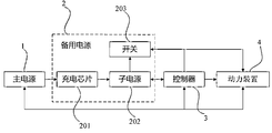
- FIG. 1 is a schematic structural diagram of a power supply system of an unmanned aerial vehicle according to Embodiment 1 of the present invention
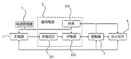
- FIG. 2 is a schematic structural diagram of a power supply system of an unmanned aerial vehicle according to Embodiment 2 of the present invention
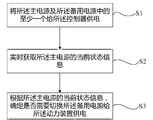
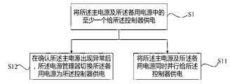
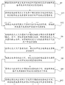
- FIG. 3 is a schematic flow chart of a power supply control method for an unmanned aerial vehicle according to Embodiment 1 of the present invention
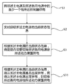
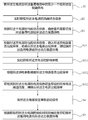
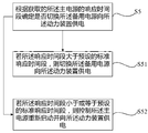
- FIG. 4 is a schematic flow chart of a power supply control method for an unmanned aerial vehicle according to Embodiment 2 of the present invention.
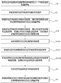
- FIG. 5 is a schematic flowchart of a power supply control method for an unmanned aerial vehicle according to Embodiment 3 of the present invention.
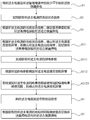
- FIG. 6 is a schematic flow chart of a power supply control method for an unmanned aerial vehicle according to Embodiment 4 of the present invention.
- FIG. 7 is a schematic flowchart of a power supply control method for an unmanned aerial vehicle according to Embodiment 5 of the present invention.
- FIG. 8 is a schematic flow chart of a power supply control method for an unmanned aerial vehicle according to Embodiment 6 of the present invention.
- FIG. 9 is a schematic flow chart of a power supply control method for an unmanned aerial vehicle according to Embodiment 7 of the present invention.
- FIG. 10 is a schematic flowchart of a power supply control method for an unmanned aerial vehicle according to Embodiment 8 of the present invention.
- FIG. 11 is a schematic structural diagram of a power supply control system for an unmanned aerial vehicle according to Embodiment 1 of the present invention.
- FIG. 1 is a schematic structural diagram of a power supply system for an unmanned aerial vehicle according to Embodiment 1 of the present invention.
- the power supply system of the unmanned aerial vehicle includes: Main power supply 1, backup power supply 2, controller 3 and power unit 4;
- At least one of the main power source 1 and the backup power source 2 is for supplying power to the controller 3;
- the controller 3 is configured to acquire current state information of the main power source 1 in real time; and determine whether it is necessary to switch the backup power source 2 to supply power to the power unit 4 according to the current state information of the main power source 1.
- the specific structure of the main power source 1 and the backup power source 2 in this embodiment is not limited, and those skilled in the art can set according to specific design requirements.
- the main power source 1 can be configured by a smart battery, and the internal battery can be utilized. Electronic circuit to measure, calculate and store battery data; and the backup power supply 2 can be set to be composed of a supercapacitor or a high-rate lithium ion battery, etc., so that when the main power source 1 is abnormal, the backup power source 2 is continuously powered for at least 1 minute.
- main power source 1 and the backup power source 2 of other configurations may be implemented as long as at least one of the main power source 1 and the backup power source 2 is used to supply power to the controller 3; and the controllers for the main power source 1 and the backup power source 2 are provided
- the specific power supply strategy of the power supply of 3 is not limited, and those skilled in the art can set according to different design requirements, for example, the power supply 1 can be set to power the controller 3 separately; or the backup power supply 2 can supply power to the controller 3 separately.
- the main power source 1 supplies power to the backup power source 2; or, the main power source 1 and the backup power source 2 simultaneously supply power to the controller 3; or, when the main power source 1 supplies power to the controller 3 abnormally (unstable power supply, power failure, etc.),
- the backup power supply 2 supplies power to the controller 3 and the like.
- the specific structure of the controller 3 is not limited, and those skilled in the art can set according to specific design requirements; of course, in order to realize the controller 3 to obtain the current state information of the main power source 1 and according to the main power source 1
- the current state information determines whether it is necessary to switch the function of the backup power source 2 to supply power to the power unit 4, and the controller 3 communicates with the main power source 1, the backup power source 2, and the power unit 4 to obtain the current state information of the main power source 1 in real time. And determining whether to switch the backup power source 2 to supply power to the power unit 4 according to the current state information of the main power source 1.
- the specific control mode for the main power source 1 in the embodiment to switch the backup power source 2 to supply power to the power unit 4 is not limited, and those skilled in the art can set according to specific design requirements, for example, the backup power source 2 can be set to be built-in.
- the charging switch 203 When the charging switch 203 is received, when the charging signal of the main power source 1 is received, the charging switch 203 of the backup power source 2 is turned on, so that the electrical connection between the backup power source 2 and the power unit 4 can be realized, thereby charging the power unit 4; or, standby
- the power source 2 is connected to a switch 203.
- the switch 203 is connected to the controller 3 and the power unit 4.
- the controller 3 When the controller 3 detects that the main power source 1 is abnormal, the controller 3 sends an open signal to the switch 203, so that the backup power source 2 and the The power unit 4 is the same, and the power unit 4 is powered.
- the controller 3 sends an open signal to the switch 203, so that the backup power source 2 and the The power unit 4 is the same, and the power unit 4 is powered.
- those skilled in the art can also adopt other forms of control, as long as the above effects can be achieved, and details are not described herein.
- the model structure of the backup power source 2 in this embodiment is not limited.
- the backup power source 2 can be configured to include: a charging chip 201, a sub-power source 202 connected to the charging chip 201, and a switch 203 connected to the sub power source 202;
- the charging chip 201 is connected to the main power source 1 for charging the sub-power source 202 to store the sub-power source 202 with a certain amount of power.
- the sub-power source 202 can be set to satisfy the instant. 30-50C discharge rate and 5C charge rate;
- a switch 203 electrically connected to the controller 3 and the power unit 4 for control under the controller 3
- the opening or closing is performed to realize whether the backup power source 2 is in communication with the power unit 4, wherein, more commonly, the switch 203 can be set as a MOS tube or a solid state relay.
- the specific structure of the power unit 4 in this embodiment is not limited, and those skilled in the art may set according to specific design requirements, such as the power unit 4 may be configured to include a motor system; or, including an electric adjustment system; Or, including the motor system and the ESC system, its main function is to power the UAV.
- the UAV when the UAV is working normally, it can be powered by the main power supply 1 alone for the controller 3; or by the backup power supply 2 alone for the controller 3; or by the main power supply 1 and the backup power supply 2 simultaneously and behaviorally controlled
- the power supply of the controller 3 is provided; or, when an abnormality occurs in the main power source 1, the backup power source 2 supplies power to the controller 3; wherein, in this embodiment, the main power source 1 and the backup power source 2 are simultaneously powered by the behavior controller 3 as an example to perform the control principle.
- the main power source 1 supplies power to the backup power source 2, the controller 3, and the power unit 4, and is in a real-time power supply state, and the backup power source 2 continues to supply power to the controller 3 after receiving power from the main power source 1, so that The controller 3 is continuously powered; the backup power source 2 is electrically connected to the power unit 4 through a switch 203, which may be built in the backup power source 2 or separately from the backup power source 2; the main power source 1 is normally the controller 3 or the power source.
- the switch 203 is in a closed state, that is, the backup power source 2 does not supply power to the power unit 4 at this time, and the unmanned aerial vehicle normally operates normally.
- the controller 3 When an accident occurs, such as a communication terminal between the main power source 1 and the controller 3 or (and) power supply interruption, since the backup power source 2 supplies power to the controller 3 in real time, the controller 3 can continue to operate; at this time, the controller 3
- the controller 3 When it is determined that the main power source 1 is abnormal, the controller 3 controls the switch 203 to be turned on, so that the backup power source 2 is in communication with the power unit 4 to supply power to the power unit 4 through the backup power source 2, thereby ensuring the normal operation of the power unit 4, which is effective. It prevents the UAV from being prone to crash when the main power supply 1 is abnormal.
- the power supply system of the unmanned aerial vehicle controls the backup power source 2 to supply power to the power unit 4 after detecting that the main power source 1 is abnormal, thereby ensuring the normal operation of the power unit 4, thereby overcoming the present situation.
- the battery of the unmanned aerial vehicle due to the battery of the unmanned aerial vehicle, it is easy to cause the UAV to crash. Even if the battery is abnormally excluded, the risk of the crash is still high for the UAV, and thus the problem is improved. Safety and reliability of unmanned aerial vehicles flying.
- the controller 3 in the first embodiment of the present invention determines whether it is necessary to switch the backup power source 2 to supply power to the power device 4, specifically:
- the backup power source 2 is switched to supply power to the power unit 4.
- the abnormality of the main power source 1 in the embodiment means that the main power source 1 cannot be normally implemented as the backup power source 2, the power device 4, and the controller 3; if the power is too low, the charging line is short-circuited or short-circuited, etc. In case, the main power supply 1 is abnormal.
- the standby power supply 2 needs to be switched as the power device. 4 to supply power; thereby reducing the probability of the UAV crashing when the main power supply 1 is abnormal, effectively improving the practicability of the system.
- the power supply strategy of the controller 3 for the main power source 1 and the backup power source 2 is not limited in the technical solution, wherein the controller 3 is guaranteed.
- main power source 1 and the backup power source 2 By setting the main power source 1 and the backup power source 2 to supply power to the controller 3 in parallel at the same time, it can be effectively realized.
- the main power source 1 is abnormal and the controller 3 cannot be powered, the power supply of the controller 3 through the backup power source 2 is still The operation can be continued without being simple, thereby ensuring the stability and reliability of the operation of the controller 3, thereby improving the reliability of the system.
- FIG. 2 is a schematic structural diagram of a power supply system for an unmanned aerial vehicle according to Embodiment 2 of the present invention.
- the present embodiment provides another power supply system for an unmanned aerial vehicle. a structure including: a main power source 1, a backup power source 2, a controller 3, and a power unit 4; wherein, the main power source 1, the backup power source 2, the controller 3, and the power unit 4 are The configurations in the first embodiment are the same as those in the first embodiment. For details, reference may be made to the above description, and details are not described herein.
- the power supply system further includes: a power manager 5 communicably connected to the main power source 1 and the backup power source 2, and power management. The device 5 is powered by the backup power source 2;
- the power manager 5 is configured to switch the backup power source 2 to supply power to the controller 3 after confirming that the main power source 1 is abnormal.
- the specific structure of the power manager 5 in this embodiment is not limited, and those skilled in the art can arbitrarily set the power manager 5 according to the functions implemented by the user.
- the power manager 5 can be set to be built in the standby. In the power source 2 or in the main power source 1.
- the main power source 1 When the power manager 5 is set to be built in the backup power source 2, the main power source 1 is in communication connection with the power manager 5 and the communication between the main power source 1 and the backup power source 2 may use different links or the same link;
- the main power source 1 can be set to communicate with the backup power source 2 through the first link, with the power manager 5 through the second link, and the power manager 5 is connected to the backup power source 2 through the third link; or
- the main power source 1 can be set to communicate with the power manager 5 through a link, and the power manager 5 is connected to the backup power source 2 through the second link; of course, those skilled in the art can also design according to different designs. Other design methods are required for the requirements, as long as the main power source 1, the backup power source 2, and the power manager 5 can achieve the corresponding functional effects, and details are not described herein again.
- the backup power source 2 and the main power source 1 and the power manager 5 can be implemented by using different or the same link.
- the specific implementation process is similar to the above manner. It should be noted that, when an abnormality occurs in the main power source 1, the power manager 5 built in the main power source 1 still operates normally, that is, the power manager 5 and the main power source 1 operate independently of each other.
- the controller 3 stops the operation because only the main power source 1 supplies power, and the power manager 5 controls the switching standby power source 2 Starting, powering the controller 3, at this time, causing the controller 3 to be in a stopped working state for a period of time, by intelligent control of the power manager 5, requiring the controller 3 to stop working within 2 seconds, thus, The situation that the UAV crashes during the period when the controller 3 stops working can be effectively prevented; in summary, the technical solution of the embodiment can achieve the effect that the main power source 1 and the backup power source 2 are not simultaneously The effect achieved by the embodiment of the behavior controller 3 power supply, however, by setting the power manager 5, the main power can be effectively guaranteed The working state of the source 1 and the backup power source 2 is managed and controlled, the workload of the controller 3 is reduced, the processing speed of the controller 3 is improved, and the accuracy and reliability of the operation of the controller 3 are ensured.
- the setting manner of the power manager 5 in this embodiment is different from the setting manner in the fourth embodiment.
- the power manager 5 is integrated in the control. Within the device 3, or the power manager 5 is separately provided from the controller 3.
- the power manager 5 and the main power source 1 and the backup power source 2 respectively communicate through different links, thereby ensuring that the power manager 5 can obtain the working state of the main power source 1 in real time.
- the active power supply 2 is effectively controlled according to the working state of the main power supply 1; in addition, the operation process of the specific control is the same as that in the above-mentioned fourth embodiment, and the above description is specifically referred to, and details are not described herein again.
- the technical solution for the controller 3 determines whether it is necessary to switch the power supply to the power device 4 according to the current state information of the power source, wherein the process is not limited. More preferably, the controller 3 is set to be specifically used for:
- the specific power supply parameters of the main power source 1 acquired by the controller 3 are not limited, and those skilled in the art can set according to specific design requirements, for example, the power supply parameter can be set as the power supply voltage, the supply current, and the power supply of the main power source 1.
- the parameters are effectively analyzed and judged to determine whether the main power supply 1 is abnormal, which effectively improves the accuracy of the judgment of the working state of the power supply, thereby ensuring the effectiveness of the unmanned aerial vehicle in the case of accurately determining the working state of the power supply. Adjustment and control further avoid the occurrence of UAV crashes.
- the present embodiment will be the main power.
- the power supply parameter of the source 1 is set to the current information of the main power source 1, and the controller 3 is specifically used for:
- the standard current threshold range can be arbitrarily set according to the conventional experience of those skilled in the art, and the standard current threshold range is related to different models and circuit structures, and therefore, those skilled in the art can set according to specific design requirements. As long as it can guarantee that the current information of the main power supply 1 is within the standard current threshold range, regardless of the size, circuit structure and battery type of the UAV, it can work normally.
- the meaning of exceeding the preset standard current threshold range in this embodiment is greater than the upper limit value of the standard current threshold range or less than the lower limit value of the standard current threshold range, for example, assuming that the standard current threshold range is [3 mA, 5mA], when the detected current information of the main power supply 1 is 0A or 1mA, obviously, the current information exceeds the standard current threshold range, it is confirmed that the main power supply 1 is abnormal (such as insufficient power); when the detected main The current information of the power source 1 is 4.2 mA, and the current information is within the standard current threshold range.
- the main power source 1 is in a normal working state; when the current information of the main power source 1 is detected as 6 mA, the current information exceeds the standard current. In the threshold range, it is confirmed that the main power source 1 is abnormal; of course, those skilled in the art can also analyze and determine the current information of the collected main power source 1 by using other analysis methods, as long as the current according to the collected main power source 1 can be realized. The information confirms whether the main power source 1 is abnormal, and will not be described here.
- the power supply parameter of the main power source 1 is set to the voltage information of the main power source 1, and the controller 3 is specifically used for:
- the standard voltage threshold range can be arbitrarily set according to the conventional experience of those skilled in the art, and the standard voltage threshold range is related to different models and circuit structures, and therefore, those skilled in the art can set according to specific design requirements. As long as it can guarantee that the voltage information of the main power supply 1 is within the standard voltage threshold range, regardless of the size, circuit structure and battery type of the UAV, it can work normally.
- the meaning of exceeding the preset standard voltage threshold range in this embodiment is greater than the standard.
- the upper limit value of the quasi-voltage threshold range or less than the lower limit of the standard voltage threshold range for example, assuming the standard voltage threshold range is [2V, 6V], when the detected main power supply 1 voltage information is 0V or 1V, it is obvious If the voltage information exceeds the standard voltage threshold range, it is confirmed that the main power supply 1 is abnormal (such as insufficient power); when the detected main power supply 1 voltage information is 4.2V, the voltage information is within the standard voltage threshold range, It is confirmed that the main power source 1 is in a normal working state; when the voltage information of the main power source 1 is detected to be 6V, the voltage information exceeds the standard voltage threshold range, and it is confirmed that the main power source 1 is abnormal; of course, those skilled in the art can also The voltage information of the collected main power source 1 is analyzed and judged by other analysis methods, as long as it can be confirmed whether the main power source 1 is abnormal according to the collected voltage information of the main power
- the power supply parameter of the main power source 1 is set as the power information of the main power source 1, and the controller 3 is specifically used for:
- the standard power threshold range can be arbitrarily set according to the conventional experience of those skilled in the art, and the standard power threshold range is related to different models and circuit structures, and therefore, those skilled in the art can set according to specific design requirements. As long as it can guarantee that the power information of the main power supply 1 is within the standard power threshold range, regardless of the size, circuit structure and battery type of the UAV, it can work normally.
- the meaning of exceeding the preset standard power threshold range in this embodiment is greater than the upper limit of the standard power threshold range or less than the lower limit of the standard power threshold range, for example, assuming that the standard power threshold range is [30% , 100%], when the detected power consumption information of the main power source 1 is 0 or 10%, obviously, the power information exceeds the standard power threshold range, it is confirmed that the main power supply 1 is abnormal (such as insufficient power); The detected power information of the main power source 1 is 60%, and the power amount information is within the standard power threshold range. Therefore, it is confirmed that the main power source 1 is in a normal working state; when the power amount information of the main power source 1 is detected to be 110%, the power amount is detected.
- the main power supply 1 is abnormal (internal short circuit, etc.); of course, those skilled in the art may also use other analysis methods to analyze and judge the collected power information of the main power supply 1 as long as It can be confirmed whether the main power source 1 is abnormal according to the collected power information of the main power source 1, I will not repeat them here.
- the specific processing manner of the main power supply 1 after the abnormality of the work is confirmed in the technical solution is not limited, and those skilled in the art can Specific design requirements are set, wherein, more preferably, the controller 3 is set to also be used for:
- Whether or not to switch the backup power source 2 to supply power to the power unit 4 is determined according to the obtained response time period of the main power source 1.
- the main power supply 1 may have a short power failure or failure. Therefore, in order to confirm whether the main power source 1 has a short abnormal operation condition, after the controller 3 confirms that the main power source 1 is abnormal, a restart signal is sent to the main power source 1 to implement the communication wake-up function for the main power source 1, and The result of the specific communication wake-up function needs to be confirmed according to the response time period of the main power source 1.
- response time period of the main power source 1 is relatively short, it is not necessary to switch the backup power source 2 to supply power to the power unit 4; If the response time period is relatively long, it is necessary to switch the backup power source 2 to supply power to the power unit 4 to prevent the UAV from crashing during the response period.
- the technical solution for determining whether to switch the power supply of the backup power source 2 to the power device 4 according to the response time period of the main power source 1 is not limited, wherein, preferably, the controller 3 is used.
- the controller 3 is used.
- the specific range of the standard response time period in this embodiment is not limited, and those skilled in the art can set according to the specific model of the unmanned aerial vehicle and the model size of the main power source 1.
- the standard response time is adopted.
- the segment is set to 2s, which means that if within 2s (excluding 2s), the main power supply 1 does not respond after receiving the restart signal, then confirm that the main power supply 1 is out. If abnormal, the controller 3 controls the switching of the backup power source 2 to supply power to the power unit 4.
- the power device 4 will not be powered by any power supply device within a time range of 2 s, and due to the inertia factor of the power device 4, during the time period, the UAV will not crash, that is, For those skilled in the art, the UAV can be saved without crashing; however, obviously, the probability of saving the UAV is directly related to the response time of the main power supply 1, and the shorter the response time, the rescue UAV The higher the probability; the longer the response time, the lower the chance of saving the UAV; therefore, the shorter the standard response time period is, the easier it is to control the UAV based on the technical solution. On the contrary, it will be more difficult to control the UAV.
- controller 3 can also be set to be specifically used for:
- the control main power source 1 is restarted and power is supplied to the power unit 4.
- the specific range of the standard response time period in this embodiment is not limited, and those skilled in the art can set according to the specific model of the unmanned aerial vehicle and the model size of the main power source 1.
- the standard response time is adopted.
- the segment is set to 2s, which means that if the main power supply 1 responds after receiving the restart signal within 2s (including 2s), it is confirmed that the main power supply 1 is restored to normal, and then restarting is performed for the power unit 4 powered by.
- the power device 4 will not be powered by any power supply device within a time range of 2 s, and due to the inertia factor of the power device 4, during the time period, the UAV will not crash, that is, For those skilled in the art, the UAV can be saved without crashing; however, obviously, the probability of saving the UAV is directly related to the response time of the main power supply 1, and the shorter the response time, the rescue UAV The higher the probability; the longer the response time, the lower the chance of saving the UAV; therefore, the shorter the standard response time period is, the easier it is to control the UAV based on the technical solution. On the contrary, it will be more difficult to control the UAV.
- controller 3 can also be set to also be used for:
- controlling the flight mode of the unmanned aerial vehicle to switch to a preset emergency standby mode includes: reducing the output power of the unmanned aerial vehicle, and controlling the unmanned aerial vehicle Decline in the preset time period until landing.
- the emergency standby mode of the embodiment needs to be implemented by the controller 3 for comprehensively controlling a plurality of devices of the unmanned aerial vehicle, such as controlling the flight direction of the unmanned aerial vehicle, so that the flight direction of the unmanned aerial vehicle is set to Facing the ground; controlling the output power of the unmanned aerial vehicle, such as reducing the output power of the unmanned aerial vehicle, so that the unmanned aerial vehicle is flying relatively slowly, so as to control the unmanned aerial vehicle to descend until a landing within a preset time period;
- the manner in which the output power of the UAV is reduced is generally achieved by reducing the output power consumption of the power unit 4.
- the preset time period it is related to the power supply time that the standby power source 2 can continue. More common, in order to prevent the crash of the UAV, the preset time period is 1 min, thus, the standby power supply is required. 2 The power supply can be continuously powered for at least 1 min, so that the safe landing of the UAV can be effectively ensured; of course, those skilled in the art can also set the preset time period to other specific numerical ranges, as long as the guarantee can be achieved. The safe landing of the human aircraft can be omitted, and will not be described here.
- the UAV By switching the flight mode of the UAV to the emergency standby mode, the UAV can be quickly and effectively lowered to landing, thereby avoiding the power failure of the controller 3 or the power unit 4 in the air, thereby making the UAV
- the occurrence of a crash situation increases the safety and reliability of the power supply system.
- the controller 3 is also set to be used for:
- the backup power source 2 Based on the response time of the main power source 1, it is determined whether or not the backup power source 2 is controlled to stop supplying power to the power unit 4.
- the controller 3 improved in this embodiment sends a restart signal to the main power source 1 again. It can also be performed after the UAV is switched from the flight mode to the preset emergency standby mode, that is, the restart signal can also be sent to the main power source 1 during the flight in the emergency standby mode; or, The aircraft is switched from the flight mode to the emergency standby mode; of course, after the UAV is landed, the main power supply 1 can be checked in detail, that is, the response time to the main power supply 1 can be set to a longer time.
- the response time of the main power supply 1 is set to be relatively short (such as 2s or 3s, etc.).
- the main power source 1 needs to be detected to determine that the main power source 1 can continue. Used to adjust the power supply strategy of the UAV during flight; as the UAV may fly in the air, it may be affected by the external flight environment, such as the temperature of the flight environment, the humidity of the flight environment, and the airflow of the flight environment.
- the main power supply 1 may be temporarily powered off or failed. Therefore, in order to confirm whether the main power supply 1 has a short abnormal operation, after the controller 3 confirms that the main power supply 1 is abnormal, a restart signal is sent to the main power supply 1.
- the result of the specific communication wake-up function needs to be confirmed according to the response time of the main power supply 1. If the response time of the main power supply 1 is relatively short, it is necessary to control the standby power supply 2 to stop. Powering the power unit 4; if the response time of the main power source 1 is long, it needs to be controlled 2 continues power supply to the power supply means 4, to ensure normal flight of an unmanned aerial vehicle.
- the specific determination manner of the controller 3 for determining whether to control the standby power source 2 to stop supplying power to the power unit 4 according to the response time of the main power source 1 is not limited, and those skilled in the art can
- the implemented function arbitrarily sets it, and, preferably, the controller 3 can be set to be specifically used for:
- the backup power source 2 is controlled to stop supplying power to the power unit 4.
- the person skilled in the art can set according to the specific detection method. Since the UAV has landed safely, the detection time of the UAV can be not limited, but Based on the detection efficiency, the standard response time can be set to 1 min, and the standard response time at this time is greater than the standard response time period of the main power source 1 in the air, so that an accurate judgment can be made on the specific working state of the main power source 1, Avoid the occurrence of misjudgment of the main power supply 1.
- the method when controlling the unmanned aerial vehicle, the method includes: the main power source 1 is fully charged by the charging chip 201 for the sub-power source 202, and the backup power source 2 and the main power source 1 simultaneously supply power to the controller 3.
- the real-time power supply state ensures that the controller 3 is continuously powered.
- the switch 203 of the backup power source 2 is in a closed state, that is, the main power source 1 supplies power to the power unit 4, and the backup power source 2 does not supply power to the power unit 4 at this time, and the unmanned aerial vehicle normally operates normally.
- the controller 3 determines that the main power source 1 is in an abnormal operating state, first sends a restart command to the main power source 1, and requests to turn on the main power source 1 again, and the time for allowing the response is within 2 seconds.
- the main power source 1 If the abnormality of the main power source 1 is excluded (such as a communication failure caused by vibration, or a temporary abnormality of the command disorder), the main power source 1 is successfully awake, the main power source 1 continues to supply power to the power unit 4, and the unmanned aerial vehicle resumes flight.
- the abnormality of the main power source 1 is excluded (such as a communication failure caused by vibration, or a temporary abnormality of the command disorder)
- the controller 3 determines that the main power source 1 is in an abnormal working state, and controls the startup of the backup power source 2 to supply power to the power unit 4. At this time, the switch 203 of the backup power source 2 is turned on, so that the backup power source 2 supplies power to the power unit 4. At the same time, the controller 3 switches the flight mode to the emergency standby mode, that is, reduces the output power consumption of the unmanned aerial vehicle, and quickly descends until landing, thereby avoiding the interruption of the electric crash.
- the controller 3 can continue to try to wake up the main power supply 1, such as abnormal elimination (such as the output voltage of the smart battery) If it is raised back to the undervoltage protection point, the power supply 1 is switched back to the main power source 1 to supply power to the power unit 4, and the output of the power source 4 to the power source 4 is turned off, so that the power source of the power unit 4 can be effectively ensured.
- abnormal elimination such as the output voltage of the smart battery
- the power supply system of the unmanned aerial vehicle provided by the technical solution provides power supply to the controller 3 by using at least one of the main power source 1 and the backup power source 2, thereby improving the flight safety stability of the controller 3, thereby overcoming the problem.
- the battery of the unmanned aerial vehicle due to the battery of the unmanned aerial vehicle, it is easy to cause the UAV to crash; even if the battery is abnormally excluded, the risk of the crash is still high for the unmanned aerial vehicle;
- the switch 203 provided in the backup power source 2 the power supply state of the backup power source 2 to the power unit 4 is switched, and the power consumption of the backup power source 2 is optimized; and specifically, the backup power source 2 is powered by a high-rate lithium ion battery or Capacitor, which supports the effect of fast charging and instantaneous large rate discharge; in addition, the UAV is switched from the flight mode to the emergency standby mode.
- the standby requirement (height, etc.) is reduced.
- the power consumption process of the backup power source 2 is reduced, and the unmanned aerial vehicle can be quickly landed to land, thereby ensuring The integrity of the unmanned aircraft, thereby improving the safety and reliability of the use of unmanned aerial vehicles.
- the embodiment provides a control method for an unmanned aerial vehicle, wherein the unmanned aerial vehicle includes: a controller, a main power source, a backup power source, and a power device;
- FIG. 3 is a power supply control method for the unmanned aerial vehicle according to Embodiment 1 of the present invention; Schematic diagram of the process; as shown in Figure 3, the method includes:
- S1 supplying at least one of a main power source and a backup power source to the controller;
- the main power source and the backup power source in the embodiment is not limited, and those skilled in the art can set according to specific design requirements.
- the main power source can be configured by a smart battery, and the internal electronic circuit can be utilized. Measuring, calculating, and storing battery data; and setting the backup power source to be composed of a supercapacitor or a high-rate lithium-ion battery, etc., so that when the main power source is abnormal, the backup power source is continuously powered for at least 1 minute, and thus the unmanned aerial vehicle
- the adjustment provides sufficient time; of course, those skilled in the art can also use other configurations of the main power source and the backup power source, as long as at least one of the main power source and the backup power source can be used to power the controller. .
- the specific power supply strategy for the power supply of the main power source and the backup power source to the controller is not limited, and those skilled in the art may set according to different design requirements, such as setting the power supply to the controller separately as the main power source; or, the backup power source The controller is powered separately, and then the main power supply supplies power to the backup power supply; or, the main power supply and the backup power supply simultaneously supply power to the controller; or, the main power supply
- the controller power supply is abnormal (power supply is unstable, power is off, etc.)
- the backup power supply supplies power to the controller, etc., as long as the power supply of at least one of the main power source and the backup power source can be realized to the controller, Let me repeat.
- the specific structure of the controller is not limited, and those skilled in the art can set according to specific design requirements.
- the controller needs to communicate with the main power source. Connect, you can get the current status information of the main power in real time.
- the specific current status information can be set by the person skilled in the art according to the specific design requirements.
- the charging current information and charging voltage information of the main power supply can be set. Charging power information and more.
- S3 Determine whether it is necessary to switch the backup power to supply power to the power device according to the current state information of the main power source.
- the specific control manner for the power supply of the main power supply switching power supply in the embodiment is not limited, and those skilled in the art can set according to specific design requirements, for example, the standby power supply can be set to have a built-in charging switch.
- the charging switch of the standby power source When receiving the charging signal of the main power source, the charging switch of the standby power source is turned on, thereby realizing the electrical connection between the standby power source and the power device, thereby charging the power device; or, the standby power source is connected to a switch, the switch and the controller and The power device is connected.
- the controller detects that the main power source is abnormal, the controller sends an open signal to the switch, so that the backup power source is the same as the power device, thereby supplying power to the power device.
- those skilled in the art may also adopt other The form of the control method, as long as the above effects can be achieved, will not be described here.
- the specific structure of the power device in this embodiment is not limited, and those skilled in the art may set according to specific design requirements, such as setting the power device to include a motor system; or, including an electric adjustment system; or Including the motor system and the ESC system, its main function is to power the unmanned aerial vehicle.
- the UAV when the UAV is working normally, it can be supplied by the main power supply separately for the controller.
- the power is supplied to the controller separately by the backup power source; or the controller is powered by the main power source and the backup power source; or, when the main power source is abnormal, the backup power source supplies power to the controller; wherein, the embodiment is the main power source Take the power supply of the controller at the same time as the standby power supply as an example to explain the control principle:
- the main power supply supplies power to the backup power supply, the controller, and the power unit, and is in a real-time power supply state.
- the backup power supply continues to supply power to the controller, thereby ensuring that the controller is continuously powered;
- the power source is electrically connected to the power unit through a switch, and the switch can be built in the standby power source or separately set with the standby power source; when the main power source normally supplies power to the controller or the power unit, the switch is turned off, that is, the standby power source is at this time.
- the power unit is not powered, and the unmanned aerial vehicle is normally in flight.
- the controller can continue to work; at this time, the controller determines that the main power supply is abnormal. Then, the controller controls the switch to be turned on, so that the backup power source is connected with the power device to supply power to the power device through the backup power source, thereby ensuring the normal operation of the power device, and effectively preventing the UAV from being prone to occur when the main power source is abnormal. The occurrence of the crash situation.
- the control method of the unmanned aerial vehicle overcomes the existing technology in the prior art by controlling the backup power supply to supply power to the power device after the controller detects that the main power source is abnormal, thereby ensuring the normal operation of the power device. Due to the battery of the unmanned aerial vehicle, it is easy to cause the UAV to crash. Even if the battery is abnormally excluded, the risk of the crash is still high for the UAV, which improves the practicality of the control method. Sex.
- FIG. 4 is a schematic flowchart of a power supply control method for an unmanned aerial vehicle according to Embodiment 2 of the present invention. Referring to FIG. 4, it is determined whether to switch standby according to current state information of the main power source.
- the power supply supplies power to the power unit, including:
- S31 According to the current status information of the main power source, confirm whether the main power source is abnormal. If it is confirmed that the main power source is abnormal, switch the backup power supply to supply power to the power unit.
- the abnormality of the main power supply in the embodiment means that the main power source cannot be normally implemented as the backup power source, the power device, and the controller; if the power is too low, the charging line is short-circuited or short-circuited, etc., The main power supply is abnormal, passing the current status information of the main power supply.
- the analysis judges that if it is determined that the main power supply is abnormal, in order to maintain the normal flight operation of the unmanned aerial vehicle, it is necessary to switch the backup power supply to supply power to the power unit; thereby reducing the probability of the UAV crashing when the main power source is abnormal.
- the practicality of the method is effectively improved.
- FIG. 5 is a schematic flowchart of a power supply control method for an unmanned aerial vehicle according to Embodiment 3 of the present invention. As shown in FIG. 5, at least one of a main power supply and a backup power supply is used to supply power to the controller. Specifically, including:
- S11 The main power supply and the backup power supply are simultaneously supplied to the controller in parallel.
- the main power supply and the backup power supply By setting the main power supply and the backup power supply to supply power to the controller in parallel at the same time, it can be effectively realized.
- the controller can still continue to work through the backup power supply. In turn, the stability and reliability of the controller operation are ensured, thereby improving the reliability of the method.
- the method provided in this embodiment is implemented based on another power supply system of an unmanned aerial vehicle, including: main power supply and standby.
- the power source, the controller, and the power device wherein the main power source, the backup power source, the controller, and the power device are the same as those in the foregoing embodiments 1 to 2, and the foregoing description may be specifically referred to, and details are not described herein;
- a power manager that is in communication with both the primary power source and the backup power source, and the power manager is powered up with the backup power source;
- S1 supplying at least one of a main power source and a backup power source to the controller, specifically:
- the controller stops working because the power is only supplied by the main power supply; the power manager controls the switching standby power to start, and supplies power to the controller. At this time, the controller is stopped for a period of time, and the intelligent control of the power manager requires the controller to stop working within 2 seconds, thus effectively preventing the UAV from stopping at the controller.
- the situation of the crash occurs during the working period; in summary, it can be seen that the technical solution achieved by the embodiment does not achieve the effect achieved by the embodiment in which the main power source and the backup power source simultaneously operate the controller power supply, however, By setting the electricity
- the source manager can effectively ensure the management and control of the working state of the main power source and the standby power source, reduce the workload of the controller, improve the processing speed of the controller, and thereby ensure the accurate and reliable operation of the controller.
- FIG. 6 is a schematic flowchart of a power supply control method for an unmanned aerial vehicle according to Embodiment 4 of the present invention. On the basis of the foregoing embodiment, referring to FIG. 6, it can be confirmed that whether the main power source is abnormal according to the current state information of the main power source. include:
- the specific power supply parameters of the main power source obtained by the controller are not limited, and those skilled in the art may set according to specific design requirements.
- the power supply parameter may be set as the power supply voltage, the supply current, the power supply charge, and the power supply of the main power source.
- S312 Determine whether the main power source is abnormal according to the power supply parameter.
- the main power supply By effectively analyzing and judging the power supply parameters of the main power supply, it is determined whether the main power supply is abnormal, which effectively improves the accuracy of the judgment of the working state of the power supply, thereby ensuring that, in the case of accurately determining the working state of the power supply,
- the effective adjustment and control of the unmanned aerial vehicle further avoids the occurrence of the UAV crash.
- the power supply parameter of the main power source is set as the current information of the main power source, and then whether the main power source is abnormal according to the power supply parameter, specifically includes:
- the standard current threshold range can be arbitrarily set according to the conventional experience of those skilled in the art, and the standard current threshold range is related to different models and circuit structures, and therefore, those skilled in the art can set according to specific design requirements. As long as it can guarantee the main power supply regardless of the size, circuit structure and battery type of the UAV The current information is within the standard current threshold and can work normally.
- the meaning of exceeding the preset standard current threshold range in this embodiment is greater than the upper limit value of the standard current threshold range or less than the lower limit value of the standard current threshold range, for example, assuming that the standard current threshold range is [3 mA, 5mA], when the detected main power supply current information is 0A or 1mA, obviously, the current information exceeds the standard current threshold range, it is confirmed that the main power supply is abnormal (such as insufficient power); when the detected main power supply The current information is 4.2 mA, and the current information is within the standard current threshold range.
- the main power source is in a normal working state; when the current information of the main power source is detected as 6 mA, the current information exceeds the standard current threshold range, and then the confirmation is performed.
- the main power supply is abnormal; of course, those skilled in the art can also use other analysis methods to analyze and judge the current information of the collected main power supply, as long as it can confirm whether the main power supply is abnormal according to the collected current information of the main power source. Yes, I will not repeat them here.
- FIG. 7 is a schematic flowchart of a power supply control method for an unmanned aerial vehicle according to Embodiment 5 of the present invention; on the basis of the foregoing embodiment 20, referring to FIG. 7, the power supply parameter of the main power source is set as a main power supply in this embodiment.
- the voltage information, and then determining whether the main power source is abnormal according to the power supply parameter specifically includes:
- FIG. 8 is a schematic flowchart of a power supply control method for an unmanned aerial vehicle according to Embodiment 6 of the present invention.
- the power supply parameter of the main power source is set as a main power supply.
- the specific processing mode of the main power source after the abnormality of the work is confirmed is not limited, and the technology in the field Personnel can be set according to specific design requirements.
- the method is set to further include:
- S5 Determine whether to switch the backup power supply to the power device according to the obtained response time period of the main power source.
- the main power supply may have a short power failure or failure. Therefore, in order to confirm whether the main power supply has a short abnormal operation, after the controller confirms that the main power supply is abnormal, a restart signal is sent to the main power supply to realize the communication wake-up function for the main power supply, and for the specific communication wake-up function. The result needs to be confirmed according to the response time period of the main power supply.
- the response time period of the main power supply is relatively short, it is not necessary to switch the backup power supply to supply power to the power unit; if the response time period of the main power supply is relatively long, the backup power supply needs to be switched. Powering the power unit to prevent the UAV from crashing during the response period.
- FIG. 9 is a schematic flowchart of a power supply control method for an unmanned aerial vehicle according to Embodiment 7 of the present invention.
- it is determined whether the response time period of the obtained main power source is determined.
- Switching the backup power supply to the power unit is set to include:
- the specific range of the standard response time period in this embodiment is not limited, and those skilled in the art may set according to the specific model of the UAV and the model size of the main power source.
- the standard response time period is adopted.
- set to 2s it means that if the main power supply responds after receiving the restart signal within 2s (including 2s), it is confirmed that the main power supply returns to normal, then it can be restarted and power is supplied to the power unit.
- the power device will not be powered by any power supply device within the time range of 2s, and due to the inertia factor of the power device, the UAV will not crash during this time period, that is, for this In the field, the unmanned aerial vehicle can be saved without crashing; however, obviously, the probability of saving the unmanned aerial vehicle is directly related to the response time of the main power supply, and the shorter the response time, the more likely the rescue of the unmanned aerial vehicle is. High; the longer the response time, the lower the chance of saving the unmanned aerial vehicle; therefore, the shorter the standard response time period set, the easier it is to control the unmanned aerial vehicle on the basis of ensuring that the technical solution can be realized; Control of unmanned aerial vehicles will be more difficult.
- FIG. 10 is a schematic flowchart of a power supply control method for an unmanned aerial vehicle according to Embodiment 8 of the present invention.
- the method further includes:
- S6 controlling the flight mode of the unmanned aerial vehicle to switch to a preset emergency standby mode, wherein the emergency standby mode comprises: reducing the output power of the unmanned aerial vehicle, and controlling the unmanned aerial vehicle to descend until a landing within a preset time period.
- the emergency standby mode of this embodiment requires multiple devices of the controller for the UAV
- the comprehensive control is realized, such as controlling the flight direction of the unmanned aerial vehicle, so that the flight direction of the unmanned aerial vehicle is set to face the ground; controlling the output power of the unmanned aerial vehicle, such as reducing the output power of the unmanned aerial vehicle,
- the unmanned aerial vehicle is made to fly slowly to control the unmanned aerial vehicle to descend until a landing within a preset time period; wherein the manner of reducing the output power of the unmanned aerial vehicle is generally to reduce the output power consumption of the power device.
- the preset time period is related to the power supply time that the standby power source can continue. More common, in order to prevent the UAV crash situation, the preset time period is 1 min, thus, the standby power supply can be required. The power supply is continuously powered for at least 1 min, so that the safe landing of the UAV can be effectively ensured. Of course, those skilled in the art can also set the preset time period to other specific numerical ranges, as long as the UAV can be guaranteed. The safe landing can be done, and will not be repeated here.
- the UAV By switching the flight mode of the UAV to the emergency standby mode, the UAV can be quickly and effectively lowered to the landing, thereby avoiding the power failure of the controller or the power device in the air, thereby causing the UAV to fall.
- the generation of the machine condition improves the safety and reliability of the control method.
- the method further includes:
- S8 Determine whether to control the standby power supply to stop supplying power to the power unit according to the response time of the main power source.
- the unmanned aerial vehicle control method provided by the technical solution utilizes at least one of a main power source and a backup power source to supply power to the controller, thereby continuously powering the controller, improving flight safety stability, and thereby overcoming the existence of the prior art. Due to the battery of the unmanned aerial vehicle, it is easy to cause the UAV to crash. Even if the battery is abnormally excluded, the risk of the crash is still high for the UAV; in addition, the UAV is The flight mode is switched to the emergency standby mode.
- the unmanned aerial vehicle can be quickly landed to land, ensuring The integrity of the unmanned aerial vehicle, which in turn improves the safety and reliability of the use of unmanned aerial vehicles.
- FIG. 11 is a schematic structural diagram of a power supply control system for an unmanned aerial vehicle according to Embodiment 1 of the present invention.
- the unmanned aerial vehicle includes: a main power supply 1 a backup power source 2, a controller 3, and a power unit 4;
- the power supply control system of the unmanned aerial vehicle includes: one or more processors 6, operating separately or in cooperation; and a processor 6 for:
- the specific structure of the main power source 1 and the backup power source 2 in this embodiment is not limited, and those skilled in the art can set according to specific design requirements.
- the main power source 1 can be configured by a smart battery, and the internal battery can be utilized. Electronic circuit to measure, calculate and store battery data; and the backup power supply 2 can be set to be composed of a supercapacitor or a high-rate lithium ion battery, etc., so that when the main power source 1 is abnormal, the backup power source 2 is continuously powered for at least 1 minute.
- the specific power supply strategy for the power supply of the main power source 1 and the backup power source 2 to the controller 3 is not limited, and those skilled in the art can set according to different design requirements, for example, the main power source 1 can be separately provided to the controller 3 for power supply. Or, the backup power supply 2 supplies power to the controller 3 separately, and then the main power supply 1 supplies power to the backup power supply 2; or, the main power supply 1 and the backup power supply 2 simultaneously supply power to the controller 3; or, the main power supply 1 supplies power to the controller 3.
- the backup power supply 2 supplies power to the controller 3, etc., as long as the power supply of at least one of the main power supply 1 and the backup power supply 2 to the controller 3 can be achieved, This will not be repeated here.
- the specific structure of the controller 3 is not limited, and those skilled in the art can set according to specific design requirements.
- the controller 3 needs to be The main power source 1 performs communication connection, and the current state information of the main power source 1 can be obtained in real time.
- the specific current state information can be set by a person skilled in the art according to specific design requirements, for example, the charging of the main power source 1 can be set. Current information, charging voltage information or charging power information, and so on.
- the controller 3 In order to realize the function of the controller 3 to determine whether it is necessary to switch the power supply of the backup power source 2 to the power unit 4 according to the current state information of the main power source 1, the controller 3 is communicably connected with the backup power source 2 and the power unit 4, thereby realizing The current state information of the power source 1 determines whether to switch the backup power source 2 to power the power unit 4.
- the specific control mode for the main power source 1 in the embodiment to switch the backup power source 2 to supply power to the power unit 4 is not limited, and those skilled in the art can set according to specific design requirements, for example, the backup power source 2 can be set to be built-in.
- the charging switch 203 When the charging switch 203 is received, when the charging signal of the main power source 1 is received, the charging switch 203 of the backup power source 2 is turned on, so that the electrical connection between the backup power source 2 and the power unit 4 can be realized, thereby charging the power unit 4; or, standby
- the power source 2 is connected to a switch 203.
- the switch 203 is connected to the controller 3 and the power unit 4.
- the controller 3 When the controller 3 detects that the main power source 1 is abnormal, the controller 3 sends an open signal to the switch 203, so that the backup power source 2 and the The power unit 4 is the same, and the power unit 4 is powered.
- the controller 3 sends an open signal to the switch 203, so that the backup power source 2 and the The power unit 4 is the same, and the power unit 4 is powered.
- those skilled in the art can also adopt other forms of control, as long as the above effects can be achieved, and details are not described herein.
- the specific structure of the power unit 4 in this embodiment is not limited, and the technology in the field Personnel can be set according to specific design requirements, such as the power unit 4 can be set to include the motor system; or, including the electric adjustment system; or, including the motor system and the ESC system, the main function of which is to The human aircraft provides power.
- the power supply control system of the UAV may further include a memory for storing program code, and the memory is communicatively coupled to the processor 6, and the processor 6 may run the program code stored in the memory.
- the above related functional operations are performed; of course, the processor 6 in the technical solution can also be configured to directly perform the above related operations by a control instruction input by the user.
- the UAV when the UAV is working normally, it can be powered by the main power supply 1 alone for the controller 3; or by the backup power supply 2 alone for the controller 3; or by the main power supply 1 and the backup power supply 2 simultaneously and behaviorally controlled
- the power supply of the controller 3 is provided; or, when an abnormality occurs in the main power source 1, the backup power source 2 supplies power to the controller 3; wherein, in this embodiment, the main power source 1 and the backup power source 2 are simultaneously powered by the behavior controller 3 as an example to perform the control principle.
- the main power source 1 supplies power to the backup power source 2, the controller 3, and the power unit 4, and is in a real-time power supply state, and the backup power source 2 continues to supply power to the controller 3 after receiving power from the main power source 1, so that The controller 3 is continuously powered; the backup power source 2 is electrically connected to the power unit 4 through a switch 203, which may be built in the backup power source 2 or separately from the backup power source 2; the main power source 1 is normally the controller 3 or the power source.
- the switch 203 is in a closed state, that is, the backup power source 2 does not supply power to the power unit 4 at this time, and the unmanned aerial vehicle normally operates normally.
- the controller 3 When an accident occurs, such as a communication terminal between the main power source 1 and the controller 3 or (and) power supply interruption, since the backup power source 2 supplies power to the controller 3 in real time, the controller 3 can continue to operate; at this time, the controller 3
- the controller 3 When it is determined that the main power source 1 is abnormal, the controller 3 controls the switch 203 to be turned on, so that the backup power source 2 is in communication with the power unit 4 to supply power to the power unit 4 through the backup power source 2, thereby ensuring the normal operation of the power unit 4, which is effective. It prevents the UAV from being prone to crash when the main power supply 1 is abnormal.
- the power supply control system of the unmanned aerial vehicle obtained by this embodiment obtains the current state information of the main power source 1 through the processor 6, and detects that the main power source 1 has an abnormal working state through the current state information, and controls the standby power source 2 to the power device. 4 power supply, to ensure the normal operation of the power unit 4, thereby overcoming the existing battery in the prior art due to the unmanned aircraft battery, it is easy to cause The crash of the unmanned aerial vehicle; even if the battery is abnormally excluded, the risk of the crash is still high for the unmanned aerial vehicle, thereby improving the safety and reliability of the UAV flight.
- the processor 6 is further configured to:
- the backup power source 2 is switched to supply power to the power unit 4.
- the processor 6 is further configured to:
- the main power source 1 and the backup power source 2 are simultaneously supplied with power to the controller 3.
- the unmanned aerial vehicle further includes: a power manager 5 communicably connected to both the main power source 1 and the backup power source 2, and the power source manager 5 and the backup power source 2 are powered;
- the processor 6 is also used to:
- the backup power source 2 is switched by the power manager 5 to supply power to the controller 3.
- the power supply control system further includes:
- the power supply parameter collecting circuit 7 is electrically connected to the processor 6 for collecting power supply parameters of the main power source 1 in real time;
- the specific structure of the power supply parameter collection circuit 7 in this embodiment is not limited, and those skilled in the art can arbitrarily set the power supply parameter according to the functions thereof, as long as the power supply parameters of the main power source 1 can be collected in real time.
- the power supply parameter acquisition circuit 7 also changes structurally with the power supply parameters.
- the power supply parameter is current information
- the power supply parameter acquisition circuit 7 is substantially a current acquisition circuit
- the power supply parameter collecting circuit 7 is substantially a voltage collecting circuit
- the power supply parameter collecting circuit 7 is substantially a current and voltage collecting circuit; of course, those skilled in the art It is easy to understand that there are substantial differences between the current collecting circuit and the voltage collecting circuit. Therefore, the power supply parameter collecting circuit in the technical solution has many different forms.
- the processor 6 is further configured to: determine whether the main power source 1 is abnormal according to the power supply parameter of the main power source 1.
- the power supply parameter of the main power source 1 is collected by the power supply parameter collecting circuit 7, the power supply parameter is sent to the processor 6; the processor 6 determines whether the main power source 1 is abnormal by analyzing and processing the power supply parameter;
- the processing procedure and the processing effect of the power supply parameters of the device 6 are the same as those of the processing and processing in the foregoing embodiment 6. For details, refer to the above description, and details are not described herein again.
- the processor 6 is specifically configured to:
- the standard current threshold range can be arbitrarily set according to the conventional experience of those skilled in the art, and the standard current threshold range is related to different models and circuit structures, and therefore, those skilled in the art can set according to specific design requirements. As long as it can guarantee that the current information of the main power supply 1 is within the standard current threshold range, regardless of the size, circuit structure and battery type of the UAV, it can work normally.
- the meaning of the standard current threshold range exceeding the preset in this embodiment is greater than the upper limit value of the standard current threshold range or less than the lower limit value of the standard current threshold range, for example, the hypothesis
- the quasi-current threshold range is [3mA, 5mA].
- the detected current information of the main power source 1 is 4.2 mA, the current information is within the standard current threshold range, therefore, it is confirmed that the main power source 1 is in a normal working state; when the current information of the main power source 1 is detected as 6 mA If the current information exceeds the standard current threshold range, it is confirmed that the main power source 1 is abnormal; of course, those skilled in the art may also analyze and analyze the current information of the collected main power source 1 by using other analysis methods, as long as the basis can be realized. The collected current information of the main power source 1 confirms whether the main power source 1 is abnormal, and details are not described herein again.
- the processor 6 is specifically configured to:
- the analysis processing procedure and the processing effect of the voltage information in the embodiment are the same as the analysis processing procedure and the processing effect in the foregoing embodiment 8. For details, reference may be made to the above description, and details are not described herein again.
- the processor 6 is specifically configured to:
- the analysis processing process and the processing effect of the power quantity information in the embodiment are the same as the analysis processing process and the processing effect in the above-mentioned ninth embodiment.
- the processor 6 is further configured to:
- the processor 6 is specifically configured to:
- the backup power source 2 is switched to supply power to the power unit 4.
- the specific range of the standard response time period in this embodiment is not limited, and those skilled in the art can set according to the specific model of the unmanned aerial vehicle and the model size of the main power source 1.
- the standard response time is adopted.
- the segment is set to 2s, which means that if the main power supply 1 does not respond after receiving the restart signal within 2s (excluding 2s), it is confirmed that the main power supply 1 is abnormal, and the controller 3 controls to switch the backup power supply 2 direction.
- the power unit 4 is powered.
- the power device 4 will not be powered by any power supply device within a time range of 2 s, and due to the inertia factor of the power device 4, during the time period, the UAV will not crash, that is, For those skilled in the art, the UAV can be saved without crashing; however, obviously, the probability of saving the UAV is directly related to the response time of the main power supply 1, and the shorter the response time, the rescue UAV The higher the probability; the longer the response time, the lower the chance of saving the UAV; therefore, the shorter the standard response time period is, the easier it is to control the UAV based on the technical solution. On the contrary, it will be more difficult to control the UAV.
- the processor 6 is further configured to:
- the control main power source 1 is restarted and power is supplied to the power unit 4.
- the processing of the response time period is less than or equal to the preset standard response time period.
- the process and the effect of the implementation are the same as those of the above-mentioned embodiment 12, and the specifics can be referred to the above description, and details are not described herein again.
- the processor 6 is further configured to:
- controlling the flight mode of the unmanned aerial vehicle to switch to a preset emergency standby mode includes: reducing the output power of the unmanned aerial vehicle, and controlling the unmanned aerial vehicle Decline in the preset time period until landing.
- the emergency standby mode of the embodiment needs to be implemented by the controller 3 for comprehensively controlling a plurality of devices of the unmanned aerial vehicle, such as controlling the flight direction of the unmanned aerial vehicle, so that the flight direction of the unmanned aerial vehicle is set to Facing the ground; controlling the output power of the unmanned aerial vehicle, such as reducing the output power of the unmanned aerial vehicle, so that the unmanned aerial vehicle is flying relatively slowly, so as to control the unmanned aerial vehicle to descend until a landing within a preset time period;
- the manner in which the output power of the UAV is reduced is generally achieved by reducing the output power consumption of the power unit 4.
- the preset time period it is related to the power supply time that the standby power source 2 can continue. More common, in order to prevent the crash of the UAV, the preset time period is 1 min, thus, the standby power supply is required. 2 The power supply can be continuously powered for at least 1 min, so that the safe landing of the UAV can be effectively ensured; of course, those skilled in the art can also set the preset time period to other specific numerical ranges, as long as the guarantee can be achieved. The safe landing of the human aircraft can be omitted, and will not be described here.
- the UAV By switching the flight mode of the UAV to the emergency standby mode, the UAV can be quickly and effectively lowered to landing, thereby avoiding the power failure of the controller 3 or the power unit 4 in the air, thereby making the UAV
- the occurrence of a crash situation increases the safety and reliability of the power supply system.
- the processor 6 is further configured to:
- the backup power source 2 Based on the response time of the main power source 1, it is determined whether or not the backup power source 2 is controlled to stop supplying power to the power unit 4.
- the implementation process and the implementation effect of resending the restart signal and determining whether to control the backup power supply 2 to stop powering the power device 4 are the same as the implementation process and the implementation effect of the above-mentioned fourteenth embodiment.
- the implementation process and the implementation effect of resending the restart signal and determining whether to control the backup power supply 2 to stop powering the power device 4 are the same as the implementation process and the implementation effect of the above-mentioned fourteenth embodiment.
- the implementation process and the implementation effect of resending the restart signal and determining whether to control the backup power supply 2 to stop powering the power device 4 are the same as the implementation process and the implementation effect of the above-mentioned fourteenth embodiment.
- the controller 3 determines whether to control whether the backup power source 2 stops supplying power to the power unit 4 according to the response time of the main power source 1 .
- the processor 6 is preferably configured to be specifically used for:
- the backup power source 2 is controlled to stop supplying power to the power unit 4.
- the person skilled in the art can set according to the specific detection method. Since the UAV has landed safely, the detection time of the UAV can be not limited, but Based on the detection efficiency, the standard response time can be set to 1 min, and the standard response time at this time is greater than the standard response time period of the main power source 1 in the air, so that an accurate judgment can be made on the specific working state of the main power source 1, Avoid the occurrence of misjudgment of the main power supply 1.
- the embodiment provides an unmanned aerial vehicle, including a power supply system, and the power supply system includes: a main power source, a backup power source, a controller, and a power device;
- At least one of a primary power source and a backup power source is used to power the controller
- the controller is configured to acquire current state information of the main power source in real time; and determine whether it is necessary to switch the backup power source to supply power to the power device according to the current state information of the main power source.
- the specific structure of the main power source and the backup power source in the embodiment is not limited, and the skill is not limited.
- the domain technician can set up according to the specific design requirements.
- the main power setting can be composed of smart battery
- the internal electronic circuit can be used to measure, calculate and store the battery data
- the standby power can be set to be super capacitor or high magnification.
- the power supply of the backup power source is continuously supplied for at least 1 minute, thereby providing sufficient time for the adjustment of the unmanned aerial vehicle; of course, other structures can be adopted by those skilled in the art.
- the main power supply and the backup power supply are only required to implement at least one of the main power supply and the backup power supply for supplying power to the controller; and the specific power supply strategy for supplying power to the controller by the main power source and the backup power source is not limited, Those skilled in the art can set according to different design requirements, such as setting the power supply to the controller separately for the main power supply; or, the backup power supply separately supplies power to the controller, and then the main power supply supplies power to the backup power supply; or, the main power supply and the backup power supply Powering the controller in parallel at the same time; or, When the main power supply gives the controller an abnormality (unstable power supply, power failure, etc.), the backup power supply supplies power to the controller, and so on.
- the specific structure of the controller is not limited, and those skilled in the art may set according to specific design requirements; of course, in order to realize the current state information of the main power source and according to the current state information of the main power source, Determining whether it is necessary to switch the function of the backup power supply to the power device, and the controller is connected with the main power source, the backup power source and the power device to obtain the current state information of the main power source in real time, and can be determined according to the current state information of the main power source. Whether to switch the backup power supply to power the power unit.
- the specific control manner for the power supply of the main power supply switching power supply in the embodiment is not limited, and those skilled in the art can set according to specific design requirements, for example, the standby power supply can be set to have a built-in charging switch.
- the charging switch of the standby power source When receiving the charging signal of the main power source, the charging switch of the standby power source is turned on, thereby realizing the electrical connection between the standby power source and the power device, thereby charging the power device; or, the standby power source is connected to a switch, the switch and the controller and The power device is connected.
- the controller detects that the main power source is abnormal, the controller sends an open signal to the switch, so that the backup power source is the same as the power device, thereby supplying power to the power device.
- those skilled in the art may also adopt other The form of the control method, as long as the above effects can be achieved, will not be described here.
- the model structure of the backup power supply in this embodiment is not limited.
- the backup power source is configured to include: a charging chip, a sub power source connected to the charging chip, and a sub power source. Switch
- the charging chip is connected to the main power source for charging the sub power source so that the sub power source stores a certain amount of power.
- the sub power source can be set to satisfy the discharge rate of 30-50C in an instant. And 5C charging rate;
- the switch is electrically connected to the controller and the power unit for opening or closing under the control of the controller to realize whether the backup power source and the power device are connected.
- the switch can be set as a MOS tube or a solid state relay. .
- the specific structure of the power device in this embodiment is not limited, and those skilled in the art may set according to specific design requirements, such as setting the power device to include a motor system; or, including an electric adjustment system; or Including the motor system and the ESC system, its main function is to power the unmanned aerial vehicle.
- the UAV when the UAV is working normally, it can be powered by the main power supply separately for the controller; or the backup power supply can separately power the controller; or the main power supply and the backup power supply can be powered by the controller at the same time; or, When the main power supply is abnormal, the backup power supply supplies power to the controller.
- the main power supply and the backup power supply are simultaneously used as the example to control the power supply.
- the main power supply supplies power to the backup power supply, the controller, and the power unit, and is in a real-time power supply state.
- the backup power supply continues to supply power to the controller, thereby ensuring that the controller is continuously powered;
- the power source is electrically connected to the power unit through a switch, and the switch can be built in the standby power source or separately set with the standby power source; when the main power source normally supplies power to the controller or the power unit, the switch is turned off, that is, the standby power source is at this time.
- the power unit is not powered, and the unmanned aerial vehicle is normally in flight.
- the controller can continue to work; at this time, the controller determines that the main power supply is abnormal. Then, the controller controls the switch to be turned on, so that the backup power source is connected with the power device to supply power to the power device through the backup power source, thereby ensuring the normal operation of the power device, and effectively preventing the UAV from being prone to occur when the main power source is abnormal. The occurrence of the crash situation.
- the unmanned aerial vehicle provided by the embodiment overcomes the existing technology in the prior art by controlling the standby power supply to supply power to the power device after the controller detects that the main power source is abnormal, thereby ensuring the normal operation of the power device.
- the battery of the aircraft can easily lead to crashes in the UAV; even if the battery is abnormally excluded, the risk of the crash is still unmanned. High problems, which in turn improve the safety and reliability of UAV flight.
- the controller is set to be specifically used for:
- the standby power source is switched to supply power to the power device.
- the main power source and the backup power source are set to be used to supply power to the controller in parallel at the same time.
- the main power supply and the backup power supply By setting the main power supply and the backup power supply to supply power to the controller in parallel at the same time, it can be effectively realized.
- the controller can still continue to work through the backup power supply. In turn, the stability and reliability of the controller work is ensured, thereby improving the reliability of the system.
- the embodiment provides a structure of another power supply system for an unmanned aerial vehicle, the structure including: a main power source, a backup power source, a controller, and a power device; wherein, the main power source, The standby power supply, the controller, and the power device are the same as those in the first embodiment and the second embodiment.
- the power supply system further includes: a communication connection with the main power source and the backup power source. Power manager, and the power manager is powered up with the backup power source;
- the power manager is used to switch the backup power supply to power the controller after confirming that the main power supply is abnormal.
- the power manager in this embodiment is not limited, and those skilled in the art may arbitrarily set the power manager according to the functions implemented by the user.
- the power manager may be set to be built in the standby power source. Or within the main power supply.
- the main power source can communicate with the power manager and the main power source can communicate with the backup power source by using different links or the same link; that is, the main power source can be set to Connected to the backup power source through the first link, to the power manager through the second link, and the power manager communicates with the backup power source through the third link; or, the primary power source can be set to pass through a link Connected to the power manager, the power manager is connected to the backup power source through the second link; of course, those skilled in the art can adopt other design methods according to different design requirements, as long as the main power source and the backup power source can be made. And the power manager can achieve the corresponding functional effects, and will not be described here.
- the backup power source and the main power source and the power manager can be implemented by using the same or the same link.
- the specific implementation process is similar to the above method, and is not described here; Note that when the main power supply is abnormal, the power manager built into the main power supply still works normally, that is, the power manager and the main power supply work independently of each other.
- the controller stops working because the power is only supplied by the main power supply; the power manager controls the switching standby power to start, and supplies power to the controller. At this time, the controller is stopped for a period of time, and the intelligent control of the power manager requires the controller to stop working within 2 seconds, thus effectively preventing the UAV from stopping at the controller.
- the setting manner of the power manager in this embodiment is different from the setting manner in the forty-seventh embodiment.
- the power manager is integrated in the controller, or the power source is integrated.
- the manager and controller are set separately.
- the power manager communicates with the main power source and the backup power source through different links, thereby ensuring that the power manager can obtain the main power in real time.
- the controller is set to be specifically used for:
- the specific power supply parameters of the main power source obtained by the controller are not limited, and those skilled in the art may set according to specific design requirements.
- the power supply parameter may be set as the power supply voltage, the supply current, the power supply charge, and the power supply of the main power source.
- the controller is set to be specifically used for:
- the standard current threshold range can be arbitrarily set according to the conventional experience of those skilled in the art, and the standard current threshold range is related to different models and circuit structures, and therefore, those skilled in the art can set according to specific design requirements. As long as it can guarantee that the current information of the main power supply is within the standard current threshold range, regardless of the size, circuit structure and battery type of the UAV, it can work normally.
- the meaning of exceeding the preset standard current threshold range in this embodiment is greater than the upper limit value of the standard current threshold range or less than the lower limit value of the standard current threshold range, for example, assuming that the standard current threshold range is [3 mA, 5mA], when the detected main power supply current information is 0A or 1mA, obviously, the current information exceeds the standard current threshold range, confirm that the main power supply appears Abnormal (such as low battery); when the detected main power supply current information is 4.2mA, the current information is within the standard current threshold range, therefore, confirm that the main power supply is in normal working condition; when detecting the main power supply current information is 6mA When the current information exceeds the standard current threshold range, it is confirmed that the main power source is abnormal; of course, those skilled in the art may also use other analysis methods to analyze and judge the current information of the collected main power source, as long as the The current information of the collected main power source can be confirmed whether the main power supply is abnormal, and will not be described here.
- the controller is set to be specifically used for:
- the processing procedure and the processing effect of the voltage information of the detected main power source in the embodiment are the same as the processing procedure and the processing effect of the detected voltage signal of the main power source in the eighth embodiment, and the specific content may be referred to the above statement. , will not repeat them here.
- the controller is set to be specifically used for:
- the processing procedure and the processing effect of the detected power information of the main power source in the embodiment are the same as the processing procedure and the processing effect of the detected power signal of the main power source in the ninth embodiment. For details, refer to the above statement. , will not repeat them here.
- the controller is set to also be used for:
- Whether to switch the backup power source to supply power to the power unit is determined according to the obtained response time period of the main power source.
- the unmanned aerial vehicle may be affected by the external flight environment when flying in the air, such as the temperature of the flight environment, the humidity of the flight environment, and the airflow of the flight environment.
- the controller confirms that the main power supply is abnormal, send a restart signal to the main power supply to increase the main power supply.
- the communication wake-up function, and the result of the specific communication wake-up function needs to be confirmed according to the response time period of the main power supply.
- response time period of the main power supply is relatively short, it is not necessary to switch the backup power supply to the power device; if the main power supply If the response time period is longer, it is necessary to switch the backup power supply to the power unit to prevent the UAV from crashing during the response period.
- the controller is set to be specifically used for:
- the backup power source is switched to supply power to the power unit.
- the specific range of the standard response time period in this embodiment is not limited, and those skilled in the art may set according to the specific model of the UAV and the model size of the main power source.
- the standard response time period is adopted. Set to 2s, which means that if within 2s (excluding 2s), the main power supply does not respond after receiving the restart signal, then confirm that the main power supply is abnormal, the controller controls to switch the backup power supply to the power unit.
- the power device will not be powered by any power supply device within the time range of 2s, and due to the inertia factor of the power device, the UAV will not crash during this time period, that is, for this In the field, the unmanned aerial vehicle can be saved without crashing; however, obviously, the probability of saving the unmanned aerial vehicle is directly related to the response time of the main power supply, and the shorter the response time, the more likely the rescue of the unmanned aerial vehicle is. High; the longer the response time, the lower the chance of saving the unmanned aerial vehicle; therefore, the shorter the standard response time period set, the easier it is to control the unmanned aerial vehicle on the basis of ensuring that the technical solution can be realized; Control of unmanned aerial vehicles will be more difficult.
- the controller is set to be specifically used for:
- the control main power is restarted and power is supplied to the power unit.
- the controller is set to be further used for:
- controlling the flight mode of the unmanned aerial vehicle to switch to a preset emergency standby mode includes: reducing the output power of the unmanned aerial vehicle, and controlling the unmanned aerial vehicle in advance Set to fall within the time period until landing.
- the emergency standby mode of the embodiment needs to be implemented by the controller for comprehensively controlling multiple devices of the unmanned aerial vehicle, such as controlling the flight direction of the unmanned aerial vehicle, so that the flight direction of the unmanned aerial vehicle is set to be oriented.
- Ground control the output power of the unmanned aerial vehicle, such as reducing the output power of the unmanned aerial vehicle, so that the unmanned aerial vehicle is flying slowly, so as to control the unmanned aerial vehicle to descend until a landing within a preset time period;
- the way to reduce the output power of the UAV is usually to reduce the output power consumption of the power unit.
- the preset time period is related to the power supply time that the standby power source can continue. More common, in order to prevent the UAV crash situation, the preset time period is 1 min, thus, the standby power supply can be required. The power supply is continuously powered for at least 1 min, so that the safe landing of the UAV can be effectively ensured. Of course, those skilled in the art can also set the preset time period to other specific numerical ranges, as long as the UAV can be guaranteed. The safe landing can be done, and will not be repeated here.
- the UAV By switching the flight mode of the UAV to the emergency standby mode, the UAV can be quickly and effectively lowered to the landing, thereby avoiding the power failure of the controller or the power device in the air, thereby causing the UAV to fall.
- the occurrence of the machine condition improves the safety and reliability of the use of the unmanned aerial vehicle. At the same time, it also reduces the production and maintenance costs of unmanned aerial vehicles and improves the market competitiveness of unmanned aerial vehicles.
- the controller is set to also be used for:
- control standby power supply stops supplying power to the power unit.
- the operation process of re-transmitting the restart signal and determining whether to control the standby power supply to stop powering the power device in the embodiment is the same as the operation process and the implementation effect in the above-mentioned fourteenth embodiment. The content of the statement will not be repeated here.
- the controller is set to be specifically used for:
- control standby power supply stops supplying power to the power unit.
- the person skilled in the art can set according to the specific detection method. Since the UAV has landed safely, the detection time of the UAV can be not limited, but Based on the efficiency of the detection, the standard response time can be set to 1 min. The standard response time at this time is greater than the standard response time period of the main power supply in the air, so that an accurate judgment can be made on the specific working state of the main power source, avoiding The main power supply has a misjudgment.
- the related apparatus and method disclosed may be implemented in other manners.
- the device embodiments described above are merely illustrative.
- the division of the modules or units is only a logical function division.
- there may be another division manner for example, multiple units or components may be used. Combinations can be integrated into another system, or some features can be ignored or not executed.
- the mutual coupling or direct coupling or communication connection shown or discussed may be an indirect coupling or communication connection through some interface, device or unit, and may be in an electrical, mechanical or other form.
- the units described as separate components may or may not be physically separated, and the components displayed as units may or may not be physical units, that is, may be located in one place, or may be distributed to multiple network units. Some or all of the units may be selected according to actual needs to achieve the purpose of the solution of the embodiment.
- each functional unit in each embodiment of the present invention may be integrated into one processing unit, or each unit may exist physically separately, or two or more units may be integrated into one unit.
- the above integrated unit can be implemented in the form of hardware or in the form of a software functional unit.
- the integrated unit if implemented in the form of a software functional unit and sold or used as a standalone product, may be stored in a computer readable storage medium.
- the technical solution of the present invention which is essential or contributes to the prior art, or all or part of the technical solution, may be embodied in the form of a software product stored in a storage medium.
- a number of instructions are included to cause a computer processor to perform all or part of the steps of the methods described in various embodiments of the present invention.
- the foregoing storage medium includes: a U disk, a removable hard disk, a read-only memory (ROM), a random access memory (RAM), a magnetic disk, or an optical disk, and the like, which can store program codes.
Landscapes
- Engineering & Computer Science (AREA)
- Power Engineering (AREA)
- Chemical & Material Sciences (AREA)
- Combustion & Propulsion (AREA)
- Aviation & Aerospace Engineering (AREA)
- Business, Economics & Management (AREA)
- Emergency Management (AREA)
- Charge And Discharge Circuits For Batteries Or The Like (AREA)
- Direct Current Feeding And Distribution (AREA)
Abstract
一种无人飞行器的供电系统包括:主电源(1)、备用电源(2)、以及控制器(3);主电源(1)及备用电源(2)中的至少一个用于给控制器(3)供电;控制器(3),用于实时获取主电源(1)的当前状态信息;并根据主电源(1)的当前状态信息,确定是否需要切换备用电源(2)给动力装置(4)供电,通过在控制器(3)检测到主电源(1)出现异常后,控制备用电源(2)对动力装置(4)进行供电,有效克服了现有技术中存在的因无人飞行器的电池原因,很容易导致无人飞行器发生坠机现象的问题。
Description
本发明涉及无人飞行器领域,尤其涉及无人飞行器及其供电系统、方法和设备。
随着电子技术和通信技术的迅猛发展,越来越多的无人飞行器、机器人等被制造。在无人飞行器技术领域,无人飞行器的研发也越来越广泛,然而,对于无人飞行器而言,其飞行安全性能至关重要。
现有技术中,无人飞行器由于电池断电造成的坠机时有发生;而发生坠机的原因主要有:1、电池短路关断输出;2、低温环境下,持续剧烈飞行导致电池电压降至欠压保护点从而关断输出;3、在低电量报警后,继续强行放电导致电池电压降至欠压保护点从而关断输出;针对以上3种情况,很容易导致无人飞行器发生坠机现象。
发明内容
针对现有技术中的上述缺陷,本发明提供一种用于解决现有技术中由于无人飞行器的电池原因,很容易导致无人飞行器发生坠机现象的问题。
本发明的第一个方面是提供一种无人飞行器的供电系统,包括:主电源、备用电源、控制器以及动力装置;
所述主电源及所述备用电源中的至少一个用于给所述控制器供电;
所述控制器,用于实时获取所述主电源的当前状态信息;并根据所述主电源的当前状态信息,确定是否需要切换所述备用电源给所述动力装置供电。
本发明的第二个方面是提供一种无人飞行器的控制方法,所述无人飞行器包括:控制器、主电源、备用电源和动力装置;
所述方法包括:
将所述主电源及所述备用电源中的至少一个给所述控制器供电;
实时获取所述主电源的当前状态信息;
根据所述主电源的当前状态信息,确定是否需要切换所述备用电源给所述动力装置供电。
本发明的第三个方面是提供另一种无人飞行器的供电系统,包括:一个或多个处理器,单独地或者协同地工作;所述处理器,用于:
将所述主电源及所述备用电源中的至少一个给所述控制器供电;
实时获取所述主电源的当前状态信息;
根据所述主电源的当前状态信息,确定是否需要切换所述备用电源给所述动力装置供电。
本发明的第四个方面是提供一种无人飞行器,包括供电系统,所述供电系统包括:主电源、备用电源、控制器以及动力装置;
所述主电源及所述备用电源中的至少一个用于给所述控制器供电;
所述控制器,用于实时获取所述主电源的当前状态信息;并根据所述主电源的当前状态信息,确定是否需要切换所述备用电源给所述动力装置供电。
本发明提供的无人飞行器及其供电系统、方法和设备,通过在控制器检测到主电源出现异常后,控制备用电源对动力装置进行供电,保证了动力装置的正常工作,进而克服了现有技术中存在的由于无人飞行器的电池原因,很容易导致无人飞行器发生坠机现象;即便将电池排除异常,对于无人飞行器而言,坠机的风险依然很高的问题,进而提高了无人飞行器飞行的安全可靠性。
图1为本发明实施例一提供的无人飞行器的供电系统的结构示意图;
图2为本发明实施例二提供的无人飞行器的供电系统的结构示意图;
图3为本发明实施例一提供的无人飞行器的供电控制方法的流程示意图;
图4为本发明实施例二提供的无人飞行器的供电控制方法的流程示意图;
图5为本发明实施例三提供的无人飞行器的供电控制方法的流程示意图;
图6为本发明实施例四提供的无人飞行器的供电控制方法的流程示意图;
图7为本发明实施例五提供的无人飞行器的供电控制方法的流程示意图;
图8为本发明实施例六提供的无人飞行器的供电控制方法的流程示意图;
图9为本发明实施例七提供的无人飞行器的供电控制方法的流程示意图;
图10为本发明实施例八提供的无人飞行器的供电控制方法的流程示意图;
图11为本发明实施例一提供的无人飞行器的供电控制系统的结构示意图。
附图标记:
1-主电源; 2-备用电源;
201-充电芯片; 202-子电源;
203-开关; 3-控制器;
4-动力装置; 5-电源管理器;
6-处理器; 7-电源供电参数采集电路。
下面结合附图,对本发明的一些实施方式作详细说明。在不冲突的情况下,下述的实施例及实施例中的特征可以相互组合。
实施例一
本实施例提供了一种无人飞行器的供电系统,图1为本发明实施例一提供的无人飞行器的供电系统的结构示意图,如图1所示,该无人飞行器的供电系统,包括:主电源1、备用电源2、控制器3以及动力装置4;
主电源1及备用电源2中的至少一个用于给控制器3供电;
控制器3,用于实时获取主电源1的当前状态信息;并根据主电源1的当前状态信息,确定是否需要切换备用电源2给动力装置4供电。
其中,对于本实施例中的主电源1和备用电源2的具体结构不做限定,本领域技术人员可以根据具体的设计需求进行设置,如可以将主电源1设置由智能电池构成,可以利用内部电子线路来测量、计算和存储电池数据;而可以将备用电源2设置为由超级电容器或者高倍率锂离子电池构成等,使得主电源1发生异常时,备用电源2的电量持续供电时间至少为1min,进而为无人飞行器的调整提供了足够的时间;当然的,本领域技术人员还可以采用
其他的结构的主电源1和备用电源2,只要能够实现主电源1及备用电源2中的至少一个用于给控制器3供电的效果即可;此外对于主电源1及备用电源2给控制器3的供电的具体供电策略不做限定,本领域技术人员可以根据不同的设计需求进行设置,如可以设置为主电源1单独给控制器3供电;或者,备用电源2单独给控制器3供电,然后主电源1给备用电源2供电;或者,主电源1和备用电源2同时并行给控制器3供电;或者,主电源1给控制器3供电出现异常(供电不稳定、断电等)时,备用电源2给控制器3供电等等。
此外,对于控制器3的具体结构不做限定,本领域技术人员可以根据具体的设计需求进行设置;当然的,为了实现该控制器3获取主电源1的当前状态信息、并根据主电源1的当前状态信息,确定是否需要切换备用电源2给动力装置4供电的功能,控制器3与主电源1、备用电源2以及动力装置4均通讯连接,即可实时获取主电源1的当前状态信息,并可以根据主电源1的当前状态信息来确定是否切换备用电源2为动力装置4供电。
另外,对于本实施例中的主电源1切换备用电源2为动力装置4供电的具体控制方式不做限定,本领域技术人员可以根据具体的设计需求进行设置,如可以将备用电源2设置为内置有充电开关203,在接收到主电源1的充电信号时,备用电源2的充电开关203打开,即可实现备用电源2与动力装置4的电连接,进而为动力装置4进行充电;或者,备用电源2连接一开关203,该开关203与控制器3和动力装置4相连接,在控制器3检测到主电源1发生异常时,控制器3向开关203发送开启信号,以使得备用电源2与动力装置4相同,进而为动力装置4供电;当然的,本领域技术人员还可以采用其他形式的控制方式,只要能够实现上述效果即可,在此不再赘述。
进一步的,对于本实施例中的备用电源2的型号结构不做限定,其中,较为优选的,可以将备用电源2设置为包括:充电芯片201、与充电芯片201相连接的子电源202以及与子电源202相连接的开关203;
充电芯片201,与主电源1相连接,用于对子电源202进行充电,以使子电源202存储一定的电量,为了提高备用电源2的充电和放电效率,可以将子电源202设置为满足瞬间30-50C的放电倍率和5C的充电倍率;
开关203,与控制器3和动力装置4电连接,用于在控制器3的控制下
进行打开或关闭,以实现备用电源2与动力装置4是否连通,其中,较为常见的,可以将开关203设置为MOS管或固态继电器。
此外,对于本实施例中的动力装置4的具体结构不做限定,本领域技术人员可以根据具体的设计需求进行设置,如可以将动力装置4设置为包括电机系统;或者,包括电调系统;或者,包括电机系统和电调系统等,其主要的功能作用是用于对无人飞行器提供动力。
在工作时,在无人飞行器正常工作时,其可以由主电源1单独为控制器3供电;或者由备用电源2单独为控制器3供电;或者由主电源1与备用电源2同时并行为控制器3供电;或者,在主电源1发生异常时,备用电源2为控制器3供电;其中,本实施例以主电源1与备用电源2同时并行为控制器3供电为例,来进行控制原理的说明:
首先,主电源1为备用电源2、控制器3以及动力装置4供电,处于实时的供电状态,而备用电源2在接受到主电源1的供电后,也持续为控制器3进行供电,这样可以保证控制器3不断电;备用电源2通过一开关203与动力装置4电连接,该开关203可以内置于备用电源2内部或者与备用电源2单独设置;在主电源1正常为控制器3或者动力装置4进行供电时,该开关203为关闭状态,即备用电源2此时不对动力装置4供电,此时无人飞行器正常飞行工作。
当发生意外时,如主电源1与控制器3之间的通信终端或(和)供电中断,由于备用电源2实时为控制器3供电,因此控制器3可以继续工作;此时,控制器3判断到主电源1异常,则控制器3控制开关203开启,以使得备用电源2与动力装置4相连通,以通过备用电源2为动力装置4供电,进而可以保证动力装置4的正常运转,有效防止了无人飞行器在主电源1发生异常时,容易出现坠机情况的产生。
本实施例提供的无人飞行器的供电系统,通过在控制器3检测到主电源1出现异常后,控制备用电源2对动力装置4进行供电,保证了动力装置4的正常工作,进而克服了现有技术中存在的由于无人飞行器的电池原因,很容易导致无人飞行器发生坠机现象;即便将电池排除异常,对于无人飞行器而言,坠机的风险依然很高的问题,进而提高了无人飞行器飞行的安全可靠性。
实施例二
在上述实施例一的基础上,继续参考附图1可知,本技术方案实施例一中的控制器3所实现的确定是否需要切换备用电源2给动力装置4供电时,具体是:
根据主电源1的当前状态信息,确定主电源1是否出现异常,若确定主电源1出现异常,则切换备用电源2为动力装置4供电。
其中,对于本实施例中的主电源1出现异常是指主电源1无法正常的实现为备用电源2、动力装置4以及控制器3进行供电;如出现了电量过低、充电线路短路或短路等情况,均会造成主电源1出现异常,在通过对主电源1当前状态信息的分析判断,若确定主电源1出现异常,为了保持无人飞行器的正常飞行操作,需要切换备用电源2为动力装置4进行供电;进而降低了无人飞行器在主电源1发生异常时出现坠机情况的概率,有效提高了该系统的实用性。
实施例三
在上述实施例一和实施例二的基础上,继续参考附图1可知,本技术方案中对于主电源1与备用电源2对控制器3的供电策略不做限定,其中,为了保证控制器3正常工作的稳定可靠性,较为优选的,将主电源1及备用电源2,设置为具体用于同时并行给控制器3供电。
通过将主电源1及备用电源2设置为同时并行给控制器3供电,可以有效的实现,在主电源1发生异常而无法对控制器3进行供电时,控制器3通过备用电源2的供电仍然可以持续不简单的进行工作,进而保证了控制器3工作的稳定可靠性,进而提高了该系统使用的可靠性。
实施例四
在上述实施例三的基础上,图2为本发明实施例二提供的无人飞行器的供电系统的结构示意图;参考附图2可知,本实施例提供了另一种无人飞行器的供电系统的结构,该结构中包括:主电源1、备用电源2、控制器3以及动力装置4;其中,主电源1、备用电源2、控制器3以及动力装置4与上述
实施例一至二中的结构相同,具体可以参考上述陈述内容,在此不再赘述;此外,该供电系统还包括:与主电源1和备用电源2均通讯连接的电源管理器5,并且电源管理器5与备用电源2通电;
电源管理器5,用于在确认主电源1出现异常后,切换备用电源2为控制器3供电。
其中,对于该实施例中的电源管理器5的具体结构不做限定,本领域技术人员可以根据其实现的功能对其进行任意设置,较为优选的,可以将电源管理器5设置为内置在备用电源2内或者主电源1内。
当将电源管理器5设置为内置于备用电源2内时,主电源1与电源管理器5进行通讯连接以及主电源1与备用电源2进行的通讯可以采用不同的链路或者同一链路;即可以将主电源1设置为通过第一链路与备用电源2相连通,通过第二链路与电源管理器5相连通,而电源管理器5通过第三链路与备用电源2相连通;或者,可以将主电源1设置为通过一链路与电源管理器5相连通,该电源管理器5通过第二链路与备用电源2相连通;当然的,本领域技术人员还可以根据不同的设计需求采用其他的设计方式,只要能够使得主电源1、备用电源2以及电源管理器5能够实现相应的功能效果即可,在此不再赘述。
而当将电源管理器5内置在主电源1时,备用电源2与主电源1以及电源管理器5可以同样采用不同或者同一链路来实现,具体的实现过程与上述方式类似,在此不再赘述;其中,需要注意的是,在主电源1发生异常时,内置于主电源1内部的电源管理器5仍然正常工作,即电源管理器5与主电源1的工作为相互独立的。
在具体控制时,在电源管理器5检测到主电源1发生异常时,此时控制器3由于只由主电源1提供电量,所以控制器3停止工作;电源管理器5则控制切换备用电源2启动,为控制器3供电,此时,使得控制器3在一段时间内为停止工作状态,通过对电源管理器5的智能控制,要求控制器3所允许停止工作的时间在2s以内,这样,可以有效地防止无人飞行器在控制器3停止工作的时间段内发生坠机的情况;综上描述可知,该实施例的技术方案所达到的效果达不到主电源1、备用电源2同时并行为控制器3供电的实施例所达到的效果,但是,通过设置的电源管理器5,可以有效的保证对主电
源1和备用电源2的工作状态进行管理、控制,减少了控制器3的工作量,提高了控制器3的处理速度,进而保证了控制器3工作的准确可靠性。
实施例五
在上述实施例四的基础上,继续参考附图2可知,本实施例中对于电源管理器5的设置方式与实施例四中的设置方式不同,具体的,将电源管理器5设集成在控制器3内,或者电源管理器5与控制器3单独分开设置。
而对于上述电源管理器5的设置结构而言,电源管理器5与主电源1和备用电源2分别通过不同的链路实现通讯,进而保证了电源管理器5可以实时获取主电源1的工作状态,并根据主电源1的工作状态对备用电源2进行有效控制;此外,在具体控制的操作过程与上述实施例四中的操作过程相同,具体可参考上述描述内容,在此不再赘述。
实施例六
在上述实施例的基础上,继续参考附图1或2可知,本技术方案对于控制器3根据电源的当前状态信息,确定是否需要切换别用电源给动力装置4供电的过程不做限定,其中,较为优选的,控制器3,设置为具体还用于:
实时获取主电源1的供电参数;
根据供电参数确定主电源1是否出现异常。
其中,对于控制器3获取的主电源1的具体供电参数不做限定,本领域技术人员可以根据具体的设计需求进行设置,如可以将供电参数设置为主电源1的供电电压、供电电流、供电电荷、供电电量、电源温度或者供电时间等等,只要能够使得控制器3通过对供电参数的分析,可以确定主电源1是否出现异常即可,在此不再赘述;通过对主电源1的供电参数进行有效的分析判断,进而确定主电源1是否出现异常,有效的提高了对电源工作状态的判断的准确性,进而保证了在对电源工作状态判断准确的情况下,对无人飞行器的有效调整与控制,进一步避免了无人飞行器坠机情况的产生。
实施例七
在上述实施例六的基础上,继续参考附图1或2可知,本实施例将主电
源1的供电参数设置为主电源1的电流信息,进而控制器3,具体还用于:
若检测到主电源1的电流信息超出预设的标准电流阈值范围,则确认主电源1出现异常。
其中,对于标准电流阈值范围可以根据本领域技术人员的常规经验进行任意设置,并且该标准电流阈值范围与不同的机型、电路结构有关,因此,本领域技术人员可以根据具体的设计需求进行设置,只要能够保证在无论无人飞行器的机型尺寸、电路结构以及电池型号是什么,均能够保证主电源1的电流信息在标准电流阈值范围内,可以正常工作即可。
此外,对于本实施例中的超出预设的标准电流阈值范围的含义为大于标准电流阈值范围的上限值或者小于标准电流阈值范围的下限值,如,假定标准电流阈值范围为[3mA,5mA],当检测到的主电源1的电流信息为0A或者1mA时,显然的,该电流信息超出了标准电流阈值范围,则确认主电源1出现异常(如电量不足);当检测到的主电源1的电流信息为4.2mA,该电流信息在标准电流阈值范围内,因此,确认主电源1为正常工作状态;当检测到主电源1的电流信息为6mA时,该电流信息超出了标准电流阈值范围,则确认主电源1出现异常;当然的,本领域技术人员还可以采用其他的分析方式对采集的主电源1的电流信息进行分析判断,只要能够实现根据所采集的主电源1的电流信息确认主电源1是否出现异常即可,在此不再赘述。
实施例八
在上述实施例六的基础上,继续参考附图1或2可知,本实施例将主电源1的供电参数设置为主电源1的电压信息,进而控制器3,具体还用于:
若检测到主电源1的电压信息超出预设的标准电压阈值范围,则确认主电源1出现异常。
其中,对于标准电压阈值范围可以根据本领域技术人员的常规经验进行任意设置,并且该标准电压阈值范围与不同的机型、电路结构有关,因此,本领域技术人员可以根据具体的设计需求进行设置,只要能够保证在无论无人飞行器的机型尺寸、电路结构以及电池型号是什么,均能够保证主电源1的电压信息在标准电压阈值范围内,可以正常工作即可。
此外,对于本实施例中的超出预设的标准电压阈值范围的含义为大于标
准电压阈值范围的上限值或者小于标准电压阈值范围的下限值,如,假定标准电压阈值范围为[2V,6V],当检测到的主电源1的电压信息为0V或者1V时,显然的,该电压信息超出了标准电压阈值范围,则确认主电源1出现异常(如电量不足);当检测到的主电源1的电压信息为4.2V,该电压信息在标准电压阈值范围内,因此,确认主电源1为正常工作状态;当检测到主电源1的电压信息为6V时,该电压信息超出了标准电压阈值范围,则确认主电源1出现异常;当然的,本领域技术人员还可以采用其他的分析方式对采集的主电源1的电压信息进行分析判断,只要能够实现根据所采集的主电源1的电压信息确认主电源1是否出现异常即可,在此不再赘述。
实施例九
在上述实施例六的基础上,继续参考附图1或2可知,本实施例将主电源1的供电参数设置为主电源1的电量信息,进而控制器3,具体还用于:
若检测到主电源1的电量信息超出预设的标准电量阈值范围,则确认主电源1出现异常。
其中,对于标准电量阈值范围可以根据本领域技术人员的常规经验进行任意设置,并且该标准电量阈值范围与不同的机型、电路结构有关,因此,本领域技术人员可以根据具体的设计需求进行设置,只要能够保证在无论无人飞行器的机型尺寸、电路结构以及电池型号是什么,均能够保证主电源1的电量信息在标准电量阈值范围内,可以正常工作即可。
此外,对于本实施例中的超出预设的标准电量阈值范围的含义为大于标准电量阈值范围的上限值或者小于标准电量阈值范围的下限值,如,假定标准电量阈值范围为[30%,100%],当检测到的主电源1的带电量信息为0或者10%时,显然的,该电量信息超出了标准电量阈值范围,则确认主电源1出现异常(如电量不足);当检测到的主电源1的电量信息为60%,该电量信息在标准电量阈值范围内,因此,确认主电源1为正常工作状态;当检测到主电源1的电量信息为110%时,该电量信息超出了标准电量阈值范围,则确认主电源1出现异常(内部出现短路等);当然的,本领域技术人员还可以采用其他的分析方式对采集的主电源1的电量信息进行分析判断,只要能够实现根据所采集的主电源1的电量信息确认主电源1是否出现异常即可,
在此不再赘述。
实施例十
在上述实施例七、八或九的基础上,继续参考附图1或2可知,本技术方案中对于确认工作发生异常后的主电源1的具体处理方式不做限定,本领域技术人员可以根据具体的设计需求进行设置,其中,较为优选的,将控制器3,设置为还用于:
在确认主电源1出现异常之后,向主电源1发送重新启动信号;
根据获取的主电源1的响应时间段确定是否切换备用电源2向动力装置4供电。
其中,由于无人飞行器在空中飞行时可能会受到外界的飞行环境影响,如受到飞行环境的温度、飞行环境湿度以及飞行环境气流等的影响,主电源1会发生短暂的断电或失效等情况,因此,为了确认主电源1是否发生了短暂的异常工作情况,在控制器3确认主电源1出现异常后,向主电源1发送重新启动信号,以实现对主电源1增加通讯唤醒功能,而对于具体的通讯唤醒功能的结果则需要根据主电源1的响应时间段来确认,如果主电源1的响应时间段较为短暂,则不需要切换备用电源2向动力装置4供电;若主电源1的响应时间段较为长久,则需要切换备用电源2向动力装置4供电,以防止无人飞行器在该响应时间段内发生坠机的情况。
实施例十一
在上述实施例十的基础上,本技术方案对于根据主电源1的响应时间段来判断是否切换备用电源2向动力装置4供电的具体过程不做限定,其中,较为优选的,将控制器3设置为具体还用于:
若响应时间段大于预设的标准响应时间段,则切换备用电源2向动力装置4供电;
其中,对于该实施例中的标准响应时间段的具体范围不做限定,本领域技术人员可以根据无人飞行器的具体型号以及主电源1的型号尺寸来进行设置,较为优选的,将标准响应时间段设置为2s,即表示,若在2s内(不包括2s),主电源1在接收到重新启动信号后没有进行响应,则确认主电源1出
现异常,则控制器3控制切换备用电源2向动力装置4供电。
在上述情况中,会使得动力装置4在2s的时间范围内没有任何供电装置进行供电,而由于动力装置4的惯性因素,在该时间段内,无人飞行器还不会发生坠机情况,即对于本领域技术人员而言,可以挽救无人飞行器不发生坠机;然而,显然的,该挽救无人飞行器的几率与主电源1的响应时间有直接关系,响应时间越短,挽救无人飞行器的几率越高;响应时间越长,挽救无人飞行器的几率越低;因此,在能够保证技术方案能够实现的基础上,设置的标准响应时间段越短,对于无人飞行器的控制会更加容易;反之则对无人飞行器的控制会更加困难。
实施例十二
在上述实施例十一的基础上,还可以将控制器3设置为具体还用于:
若响应时间段小于或等于预设的标准响应时间段,则控制主电源1重新启动并向动力装置4供电。
其中,对于该实施例中的标准响应时间段的具体范围不做限定,本领域技术人员可以根据无人飞行器的具体型号以及主电源1的型号尺寸来进行设置,较为优选的,将标准响应时间段设置为2s,即表示,若在2s内(包括2s),主电源1在接收到重新启动信号后进行响应,则确认主电源1恢复正常,即可进行重新启动,并为动力装置4进行供电。
在上述情况中,会使得动力装置4在2s的时间范围内没有任何供电装置进行供电,而由于动力装置4的惯性因素,在该时间段内,无人飞行器还不会发生坠机情况,即对于本领域技术人员而言,可以挽救无人飞行器不发生坠机;然而,显然的,该挽救无人飞行器的几率与主电源1的响应时间有直接关系,响应时间越短,挽救无人飞行器的几率越高;响应时间越长,挽救无人飞行器的几率越低;因此,在能够保证技术方案能够实现的基础上,设置的标准响应时间段越短,对于无人飞行器的控制会更加容易;反之则对无人飞行器的控制会更加困难。
实施例十三
在上述实施例十一的基础上,还可以将控制器3设置为还用于:
在切换备用电源2向动力装置4供电之后,控制无人飞行器的飞行模式切换为预设的紧急备降模式,其中,紧急备降模式包括:降低无人飞行器的输出功率,并控制无人飞行器在预设时间段内下降直至着陆。
具体的,该实施例的紧急备降模式需要控制器3对无人飞行器的多个装置进行综合控制所实现的,如对无人飞行器的飞行方向进行控制,使得无人飞行器的飞行方向设置为朝向地面;对无人飞行器的输出功率进行控制,如降低无人飞行器的输出功率,以使得无人飞行器飞行的较为缓慢,以实现控制无人飞行器在预设时间段内下降直至着陆;其中,实现降低无人飞行器的输出功率的方式通常情况为降低动力装置4的输出功耗。
而对于预设时间段与备用电源2所能够持续的供电时间有关,较为常见的,为了防止无人飞行器的坠机情况的产生,将预设时间段为1min,这样,也就要求,备用电源2可以持续进行供电的时间至少为1min,这样才可以有效地保证无人飞行器的安全着陆;当然的,本领域技术人员还可以将预设时间段设置为其他具体数值范围,只要能够实现保证无人飞行器的安全着陆即可,在此不再赘述。
通过将无人飞行器的飞行模式切换为紧急备降模式,可以快速、有效地实现将无人飞行器下降至着陆,从而避免了控制器3或者动力装置4在空中发生断电,进而使得无人飞行器发生坠机情况的产生,提高了该供电系统使用的安全可靠性。
实施例十四
在上述实施例十三的基础上,为了进一步确认主电源1发生异常的原因,若主电源1由于飞行环境的影响而发生短暂的异常时,则说明主电源1能够恢复并继续使用,当主电源1并非发生短暂的异常,则说明主电源1不能够继续使用,具体的,将控制器3,还设置为用于:
在控制无人飞行器的飞行模式切换为预设的紧急备降模式之后,并在无人飞行器着陆后,再次向主电源1发送重新启动信号;
根据主电源1的响应时间,确定是否控制备用电源2停止对动力装置4进行供电。
其中,该实施例中提高的控制器3再次向主电源1发送重新启动信号,
也可以在无人飞行器由飞行模式切换为预设的紧急备降模式之后进行,即在飞行处于紧急备降模式的过程中也可以向主电源1发送重新启动信号;或者,还可以在无人飞行器由飞行模式切换为紧急备降模式的过程中进行;当然的,在无人飞行器着陆后,可以对主电源1进行较为细致的检查,即对主电源1的响应时间可以设置为较长时间(如1min或2min等),而在无人飞行器处于紧急备降模式的过程中,由于动力装置4需要及时通过主电源1或者备用电源2进行供电,否则会发生坠机的情况,因此,对主电源1的响应时间设置为较为短暂(如2s或3s等)。
而对于无人飞行器着陆后,再次向主电源1发送重新启动信号时,由于无人飞行器已经着陆,因此避免了发生坠机的风险;但是需要对主电源1进行检测,确定主电源1能够继续使用,以调整无人飞行器在飞行时的供电策略;由于无人飞行器在空中飞行时,可能会受到外界的飞行环境影响,如受到飞行环境的温度、飞行环境湿度以及飞行环境气流等的影响,主电源1会发生短暂的断电或失效等情况,因此,为了确认主电源1是否发生了短暂的异常工作情况,在控制器3确认主电源1出现异常后,向主电源1发送重新启动信号,以实现对主电源1增加通讯唤醒功能,而对于具体的通讯唤醒功能的结果则需要根据主电源1的响应时间来确认,如果主电源1的响应时间较为短暂,则需要控制备用电源2停止向动力装置4供电;若主电源1的响应时间段较为长久,则需要控制备用电源2继续向动力装置4供电,以保证无人飞行器的正常飞行。
实施例十五
在上述实施例十四的基础上,对于控制器3根据主电源1的响应时间,确定是否控制备用电源2停止对动力装置4进行供电的具体判断方式不做限定,本领域技术人员可以根据其实现的功能对其进行任意设置,其中,较为优选的,可以将控制器3设置为具体用于:
若响应时间大于预设的标准响应时间,则控制备用电源2继续对动力装置4进行供电;或者,
若响应时间小于或等于预设的标准响应时间,则控制备用电源2停止对动力装置4进行供电。
其中,对于该实施例中的标准响应时间,本领域技术人员可以根据具体的检测方法进行设置,由于无人飞行器已经安全着陆,因此,对于无人飞行器的检测时间的长短可以不做限定,但是基于检测的效率,可以将标准响应时间设置为1min,此时的标准响应时间大于在空中时对主电源1的标准响应时间段,这样可以对主电源1的具体工作状态做一个准确的判断,避免对主电源1发生误判情况的产生。
基于上述具体实施例的基础上,在对于无人飞行器进行控制时,具体包括:主电源1通过充电芯片201为子电源202充满电,备用电源2和主电源1同时为控制器3供电,处于实时的供电状态,从而可以保证控制器3不断电。在主电源1正常供电的情况下,备用电源2的开关203为关闭状态,即主电源1为动力装置4供电,备用电源2此时不对动力装置4供电,此时无人飞行器正常飞行工作。
当发生意外时,如主电源1与控制器3之间的通信终端或(和)供电中断,由于备用电源2实时为控制器3供电,因此控制器3继续工作。此时,控制器3判断到主电源1处于异常工作状态,首先对主电源1发送重新启动指令,要求再次打开主电源1输出,允许响应的时间为2秒内。
如果主电源1的异常排除(如震动导致的通信接触不良,或指令紊乱的临时异常),成功唤醒主电源1,则主电源1继续对动力装置4供电,无人飞行器恢复飞行。
如果主电源1唤醒失败,控制器3判断主电源1处于异常工作状态,控制启动备用电源2对动力装置4供电,此时打开备用电源2的开关203,使得备用电源2对动力装置4供电,同时控制器3将飞行模式切换为紧急备降模式,即降低无人飞行器的输出功耗,快速下降直至着陆,从而避免空中断电坠机。
在无人飞行器切换为紧急备降模式的过程中或者已经切换为紧急备降模式之后或者在已经着陆之后,控制器3均可以继续尝试唤醒主电源1,如异常排除(如智能电池的输出电压回升至欠压保护点以上),则再次切换回主电源1为动力装置4进行供电,关闭备用电源2对动力装置4的输出,这样可以有效地保证动力装置4的电量来源。
本技术方案提供的无人飞行器的供电系统,由于采用主电源1和备用电源2中的至少一个对控制器3进行供电,从而起到控制器3不断电,提高飞行安全稳定性,进而克服了现有技术中存在的由于无人飞行器的电池原因,很容易导致无人飞行器发生坠机现象;即便将电池排除异常,对于无人飞行器而言,坠机的风险依然很高的问题;此外,通过备用电源2中设置的开关203,起到备用电源2对动力装置4的供电状态切换,优化了对备用电源2的电量使用;而具体的,将备用电源2由于采用高倍率锂离子电池或电容器,从而起到支持快速充电、瞬间大倍率放电的效果;另外,将无人飞行器由飞行模式切换至紧急备降模式,具体的,通过降低输出功耗,降低了备降要求(高度等),同时降低了备用电源2的电量消耗过程,可以实现使得无人飞行器快速降落至着陆,保证了对无人飞行器的完整性,进而提高了无人飞行器使用的安全可靠性。
实施例十六
本实施例提供了一种无人飞行器的控制方法,其中,无人飞行器包括:控制器、主电源、备用电源和动力装置;图3为本发明实施例一提供的无人飞行器的供电控制方法的流程示意图;如图3所示,该方法包括:
S1:将主电源及备用电源中的至少一个给控制器供电;
其中,对于本实施例中的主电源和备用电源的具体结构不做限定,本领域技术人员可以根据具体的设计需求进行设置,如可以将主电源设置由智能电池构成,可以利用内部电子线路来测量、计算和存储电池数据;而可以将备用电源设置为由超级电容器或者高倍率锂离子电池构成等,使得主电源发生异常时,备用电源的电量持续供电时间至少为1min,进而为无人飞行器的调整提供了足够的时间;当然的,本领域技术人员还可以采用其他的结构的主电源和备用电源,只要能够实现主电源及备用电源中的至少一个用于给控制器供电的效果即可。
此外,对于主电源及备用电源给控制器的供电的具体供电策略不做限定,本领域技术人员可以根据不同的设计需求进行设置,如可以设置为主电源单独给控制器供电;或者,备用电源单独给控制器供电,然后主电源给备用电源供电;或者,主电源和备用电源同时并行给控制器供电;或者,主电源给
控制器供电出现异常(供电不稳定、断电等)时,备用电源给控制器供电等等,只要能够实现将主电源及备用电源中的至少一个给控制器供电的效果即可,在此不再赘述。
S2:实时获取主电源的当前状态信息;
其中,对于控制器的具体结构不做限定,本领域技术人员可以根据具体的设计需求进行设置;当然的,为了实现该控制器获取主电源的当前状态信息,需要将控制器与主电源进行通讯连接,即可实时获取主电源的当前状态信息,当然的,具体的当前状态信息,本领域技术人员可以根据具体的设计需求进行设置,如可以设置为主电源的充电电流信息、充电电压信息或者充电电量信息等等。
S3:根据主电源的当前状态信息,确定是否需要切换备用电源给动力装置供电。
为了实现该控制器根据主电源的当前状态信息,确定是否需要切换备用电源给动力装置供电的功能,控制器与备用电源以及动力装置均通讯连接,即可实现根据主电源的当前状态信息来确定是否切换备用电源为动力装置供电。
另外,对于本实施例中的主电源切换备用电源为动力装置供电的具体控制方式不做限定,本领域技术人员可以根据具体的设计需求进行设置,如可以将备用电源设置为内置有充电开关,在接收到主电源的充电信号时,备用电源的充电开关打开,即可实现备用电源与动力装置的电连接,进而为动力装置进行充电;或者,备用电源连接一开关,该开关与控制器和动力装置相连接,在控制器检测到主电源发生异常时,控制器向开关发送开启信号,以使得备用电源与动力装置相同,进而为动力装置供电;当然的,本领域技术人员还可以采用其他形式的控制方式,只要能够实现上述效果即可,在此不再赘述。
此外,对于本实施例中的动力装置的具体结构不做限定,本领域技术人员可以根据具体的设计需求进行设置,如可以将动力装置设置为包括电机系统;或者,包括电调系统;或者,包括电机系统和电调系统等,其主要的功能作用是用于对无人飞行器提供动力。
在工作时,在无人飞行器正常工作时,其可以由主电源单独为控制器供
电;或者由备用电源单独为控制器供电;或者由主电源与备用电源同时并行为控制器供电;或者,在主电源发生异常时,备用电源为控制器供电;其中,本实施例以主电源与备用电源同时并行为控制器供电为例,来进行控制原理的说明:
首先,主电源为备用电源、控制器以及动力装置供电,处于实时的供电状态,而备用电源在接受到主电源的供电后,也持续为控制器进行供电,这样可以保证控制器不断电;备用电源通过一开关与动力装置电连接,该开关可以内置于备用电源内部或者与备用电源单独设置;在主电源正常为控制器或者动力装置进行供电时,该开关为关闭状态,即备用电源此时不对动力装置供电,此时无人飞行器正常飞行工作。
当发生意外时,如主电源与控制器之间的通信终端或(和)供电中断,由于备用电源实时为控制器供电,因此控制器可以继续工作;此时,控制器判断到主电源异常,则控制器控制开关开启,以使得备用电源与动力装置相连通,以通过备用电源为动力装置供电,进而可以保证动力装置的正常运转,有效防止了无人飞行器在主电源发生异常时,容易出现坠机情况的产生。
本实施例提供的无人飞行器的控制方法,通过在控制器检测到主电源出现异常后,控制备用电源对动力装置进行供电,保证了动力装置的正常工作,进而克服了现有技术中存在的由于无人飞行器的电池原因,很容易导致无人飞行器发生坠机现象;即便将电池排除异常,对于无人飞行器而言,坠机的风险依然很高的问题,进而提高了该控制方法的实用性。
实施例十七
在上述实施例十六的基础上,图4为本发明实施例二提供的无人飞行器的供电控制方法的流程示意图;参考附图4可知,根据主电源的当前状态信息,确定是否需要切换备用电源给动力装置供电,具体包括:
S31:根据主电源的当前状态信息,确认主电源是否出现异常,若确认主电源出现异常,则切换备用电源给动力装置供电。
其中,对于本实施例中的主电源出现异常是指主电源无法正常的实现为备用电源、动力装置以及控制器进行供电;如出现了电量过低、充电线路短路或短路等情况,均会造成主电源出现异常,在通过对主电源当前状态信息
的分析判断,若确定主电源出现异常,为了保持无人飞行器的正常飞行操作,需要切换备用电源为动力装置进行供电;进而降低了无人飞行器在主电源发生异常时出现坠机情况的概率,有效提高了该方法的实用性。
实施例十八
在上述实施例十七的基础上,图5为本发明实施例三提供的无人飞行器的供电控制方法的流程示意图,如图5可知,将主电源及备用电源中的至少一个给控制器供电,具体包括:
S11:将主电源及备用电源同时并行给控制器供电。
通过将主电源及备用电源设置为同时并行给控制器供电,可以有效的实现,在主电源发生异常而无法对控制器进行供电时,控制器通过备用电源的供电仍然可以持续不简单的进行工作,进而保证了控制器工作的稳定可靠性,进而提高了该方法使用的可靠性。
实施例十九
在上述实施例十七的基础上,继续参考附图5可知,本实施例所提供的方法是基于另一种无人飞行器的供电系统所实现的,该无人飞行器中包括:主电源、备用电源、控制器以及动力装置;其中,主电源、备用电源、控制器以及动力装置与上述实施例一至二中的结构相同,具体可以参考上述陈述内容,在此不再赘述;此外,无人飞行器还包括:与主电源和备用电源均通讯连接的电源管理器,并且电源管理器与备用电源通电;
S1:将主电源及备用电源中的至少一个给控制器供电,具体包括:
S12:在确认主电源出现异常后,电源管理器切换备用电源为控制器供电。
在具体控制时,在电源管理器检测到主电源发生异常时,此时控制器由于只由主电源提供电量,所以控制器停止工作;电源管理器则控制切换备用电源启动,为控制器供电,此时,使得控制器在一段时间内为停止工作状态,通过对电源管理器的智能控制,要求控制器所允许停止工作的时间在2s以内,这样,可以有效地防止无人飞行器在控制器停止工作的时间段内发生坠机的情况;综上描述可知,该实施例的技术方案所达到的效果达不到主电源、备用电源同时并行为控制器供电的实施例所达到的效果,但是,通过设置的电
源管理器,可以有效的保证对主电源和备用电源的工作状态进行管理、控制,减少了控制器的工作量,提高了控制器的处理速度,进而保证了控制器工作的准确可靠性。
实施例二十
图6为本发明实施例四提供的无人飞行器的供电控制方法的流程示意图;在上述实施例的基础上,参考附图6可知,根据主电源的当前状态信息,确认主电源是否出现异常,包括:
S311:实时获取主电源的供电参数;
其中,对于控制器获取的主电源的具体供电参数不做限定,本领域技术人员可以根据具体的设计需求进行设置,如可以将供电参数设置为主电源的供电电压、供电电流、供电电荷、供电电量、电源温度或者供电时间等等,只要能够使得控制器通过对供电参数的分析,可以确定主电源是否出现异常即可,在此不再赘述。
S312:根据供电参数确定主电源是否出现异常。
通过对主电源的供电参数进行有效的分析判断,进而确定主电源是否出现异常,有效的提高了对电源工作状态的判断的准确性,进而保证了在对电源工作状态判断准确的情况下,对无人飞行器的有效调整与控制,进一步避免了无人飞行器坠机情况的产生。
实施例二十一
在上述实施例二十的基础上,继续参考附图6可知,本实施例将主电源的供电参数设置为主电源的电流信息,进而根据供电参数确定主电源是否出现异常,具体包括:
S3121:若检测到主电源的电流信息超出预设的标准电流阈值范围,则确认主电源出现异常。
其中,对于标准电流阈值范围可以根据本领域技术人员的常规经验进行任意设置,并且该标准电流阈值范围与不同的机型、电路结构有关,因此,本领域技术人员可以根据具体的设计需求进行设置,只要能够保证在无论无人飞行器的机型尺寸、电路结构以及电池型号是什么,均能够保证主电源的
电流信息在标准电流阈值范围内,可以正常工作即可。
此外,对于本实施例中的超出预设的标准电流阈值范围的含义为大于标准电流阈值范围的上限值或者小于标准电流阈值范围的下限值,如,假定标准电流阈值范围为[3mA,5mA],当检测到的主电源的电流信息为0A或者1mA时,显然的,该电流信息超出了标准电流阈值范围,则确认主电源出现异常(如电量不足);当检测到的主电源的电流信息为4.2mA,该电流信息在标准电流阈值范围内,因此,确认主电源为正常工作状态;当检测到主电源的电流信息为6mA时,该电流信息超出了标准电流阈值范围,则确认主电源出现异常;当然的,本领域技术人员还可以采用其他的分析方式对采集的主电源的电流信息进行分析判断,只要能够实现根据所采集的主电源的电流信息确认主电源是否出现异常即可,在此不再赘述。
实施例二十二
图7为本发明实施例五提供的无人飞行器的供电控制方法的流程示意图;在上述实施例二十的基础上,参考附图7可知,本实施例将主电源的供电参数设置为主电源的电压信息,进而根据供电参数确定主电源是否出现异常,具体包括:
S3122:若检测到主电源的电压信息超出预设的标准电压阈值范围,则确认主电源出现异常。
其中,本实施例中对标准电压阈值范围的定义以及具体步骤的实现方式以及实现效果与实施例八的实现方式以及实现效果相同,具体可参考上述陈述内容,在此不再赘述。
实施例二十三
图8为本发明实施例六提供的无人飞行器的供电控制方法的流程示意图;在上述实施例二十的基础上,参考附图8可知,本实施例将主电源的供电参数设置为主电源的电量信息,进而根据供电参数确定主电源是否出现异常,具体包括:
S3123:若检测到主电源的电量信息超出预设的标准电量阈值范围,则确认主电源出现异常。
其中,本实施例中对标准电压电量范围的定义以及具体步骤的实现方式以及实现效果与实施例九的实现方式以及实现效果相同,具体可参考上述陈述内容,在此不再赘述。
实施例二十四
在上述实施例二十一、二十二或二十三的基础上,参考附图6-8可知,技术方案中对于确认工作发生异常后的主电源的具体处理方式不做限定,本领域技术人员可以根据具体的设计需求进行设置,其中,较为优选的,将方法设置为还包括:
S4:将在确认主电源出现异常之后,向主电源发送重新启动信号;
S5:根据获取的主电源的响应时间段确定是否切换备用电源向动力装置供电。
其中,由于无人飞行器在空中飞行时可能会受到外界的飞行环境影响,如受到飞行环境的温度、飞行环境湿度以及飞行环境气流等的影响,主电源会发生短暂的断电或失效等情况,因此,为了确认主电源是否发生了短暂的异常工作情况,在控制器确认主电源出现异常后,向主电源发送重新启动信号,以实现对主电源增加通讯唤醒功能,而对于具体的通讯唤醒功能的结果则需要根据主电源的响应时间段来确认,如果主电源的响应时间段较为短暂,则不需要切换备用电源向动力装置供电;若主电源的响应时间段较为长久,则需要切换备用电源向动力装置供电,以防止无人飞行器在该响应时间段内发生坠机的情况。
实施例二十五
图9为本发明实施例七提供的无人飞行器的供电控制方法的流程示意图;在上述实施例二十四的基础上,参考附图9可知,将根据获取的主电源的响应时间段确定是否切换备用电源向动力装置供电,设置为具体包括:
S52:若响应时间段大于预设的标准响应时间段,则切换备用电源向动力装置供电。
其中,本实施例中对标准响应时间段的定义以及具体步骤的实现方式以及实现效果与实施例十一的实现方式以及实现效果相同,具体可参考上述陈
述内容,在此不再赘述。
实施例二十六
在上述实施例二十四的基础上,继续参考附图9可知,还可以将根据获取的主电源的响应时间段确定是否切换备用电源向动力装置供电,设置为具体包括:
S51:若响应时间段小于或等于预设的标准响应时间段,则控制主电源重新启动并向动力装置供电。
其中,对于该实施例中的标准响应时间段的具体范围不做限定,本领域技术人员可以根据无人飞行器的具体型号以及主电源的型号尺寸来进行设置,较为优选的,将标准响应时间段设置为2s,即表示,若在2s内(包括2s),主电源在接收到重新启动信号后进行响应,则确认主电源恢复正常,即可进行重新启动,并为动力装置进行供电。
在上述情况中,会使得动力装置在2s的时间范围内没有任何供电装置进行供电,而由于动力装置的惯性因素,在该时间段内,无人飞行器还不会发生坠机情况,即对于本领域技术人员而言,可以挽救无人飞行器不发生坠机;然而,显然的,该挽救无人飞行器的几率与主电源的响应时间有直接关系,响应时间越短,挽救无人飞行器的几率越高;响应时间越长,挽救无人飞行器的几率越低;因此,在能够保证技术方案能够实现的基础上,设置的标准响应时间段越短,对于无人飞行器的控制会更加容易;反之则对无人飞行器的控制会更加困难。
实施例二十七
图10为本发明实施例八提供的无人飞行器的供电控制方法的流程示意图;在上述实施例的基础上,参考附图10可知,在切换备用电源向动力装置供电之后,还包括:
S6:控制无人飞行器的飞行模式切换为预设的紧急备降模式,其中,紧急备降模式包括:降低无人飞行器的输出功率,并控制无人飞行器在预设时间段内下降直至着陆。
具体的,该实施例的紧急备降模式需要控制器对无人飞行器的多个装置
进行综合控制所实现的,如对无人飞行器的飞行方向进行控制,使得无人飞行器的飞行方向设置为朝向地面;对无人飞行器的输出功率进行控制,如降低无人飞行器的输出功率,以使得无人飞行器飞行的较为缓慢,以实现控制无人飞行器在预设时间段内下降直至着陆;其中,实现降低无人飞行器的输出功率的方式通常情况为降低动力装置的输出功耗。
而对于预设时间段与备用电源所能够持续的供电时间有关,较为常见的,为了防止无人飞行器的坠机情况的产生,将预设时间段为1min,这样,也就要求,备用电源可以持续进行供电的时间至少为1min,这样才可以有效地保证无人飞行器的安全着陆;当然的,本领域技术人员还可以将预设时间段设置为其他具体数值范围,只要能够实现保证无人飞行器的安全着陆即可,在此不再赘述。
通过将无人飞行器的飞行模式切换为紧急备降模式,可以快速、有效地实现将无人飞行器下降至着陆,从而避免了控制器或者动力装置在空中发生断电,进而使得无人飞行器发生坠机情况的产生,提高了该控制方法使用的安全可靠性。
实施例二十八
在上述实施例二十七的基础上,继续参考附图10可知,在控制无人飞行器的飞行模式切换为预设的紧急备降模式之后,该方法还包括:
S7:在无人飞行器着陆后,再次向主电源发送重新启动信号;
S8:根据主电源的响应时间,确定是否控制备用电源停止对动力装置进行供电。
其中,本实施例中对响应时间的分析判断以及具体步骤的实现方式以及实现效果与实施例十四的实现方式以及实现效果相同,具体可参考上述陈述内容,在此不再赘述。
实施例二十九
在上述实施例二十八的基础上,继续参考附图10可知,根据主电源的响应时间,确定是否控制备用电源停止对动力装置进行供电,具体包括:
S81:若响应时间大于预设的标准响应时间,则控制备用电源继续对动力
装置进行供电;或者,
S82:若响应时间小于或等于预设的标准响应时间,则控制备用电源停止对动力装置进行供电。
其中,本实施例中对标准响应时间的定义以及具体步骤的实现方式以及实现效果与实施例十四的实现方式以及实现效果相同,具体可参考上述陈述内容,在此不再赘述。
技术方案提供的无人飞行器的控制方法,由于采用主电源和备用电源中的至少一个对控制器进行供电,从而起到控制器不断电,提高飞行安全稳定性,进而克服了现有技术中存在的由于无人飞行器的电池原因,很容易导致无人飞行器发生坠机现象;即便将电池排除异常,对于无人飞行器而言,坠机的风险依然很高的问题;另外,将无人飞行器由飞行模式切换至紧急备降模式,具体的,通过降低输出功耗,降低了备降要求(高度等),同时降低了备用电源的电量消耗过程,可以实现使得无人飞行器快速降落至着陆,保证了对无人飞行器的完整性,进而提高了无人飞行器使用的安全可靠性。
实施例三十
本实施例提供了一种无人飞行器的供电控制系统,图11为本发明实施例一提供的无人飞行器的供电控制系统的结构示意图,如图11所示,无人飞行器包括:主电源1、备用电源2、控制器3以及动力装置4;该无人飞行器的供电控制系统包括:一个或多个处理器6,单独地或者协同地工作;处理器6,用于:
将主电源1及备用电源2中的至少一个给控制器3供电;
其中,对于本实施例中的主电源1和备用电源2的具体结构不做限定,本领域技术人员可以根据具体的设计需求进行设置,如可以将主电源1设置由智能电池构成,可以利用内部电子线路来测量、计算和存储电池数据;而可以将备用电源2设置为由超级电容器或者高倍率锂离子电池构成等,使得主电源1发生异常时,备用电源2的电量持续供电时间至少为1min,进而为无人飞行器的调整提供了足够的时间;当然的,本领域技术人员还可以采用其他的结构的主电源1和备用电源2,只要能够实现主电源1及备用电源2中的至少一个用于给控制器3供电的效果即可。
此外,对于主电源1及备用电源2给控制器3的供电的具体供电策略不做限定,本领域技术人员可以根据不同的设计需求进行设置,如可以设置为主电源1单独给控制器3供电;或者,备用电源2单独给控制器3供电,然后主电源1给备用电源2供电;或者,主电源1和备用电源2同时并行给控制器3供电;或者,主电源1给控制器3供电出现异常(供电不稳定、断电等)时,备用电源2给控制器3供电等等,只要能够实现将主电源1及备用电源2中的至少一个给控制器3供电的效果即可,在此不再赘述。
实时获取主电源1的当前状态信息;
其中,对于控制器3的具体结构不做限定,本领域技术人员可以根据具体的设计需求进行设置;当然的,为了实现该控制器3获取主电源1的当前状态信息,需要将控制器3与主电源1进行通讯连接,即可实时获取主电源1的当前状态信息,当然的,具体的当前状态信息,本领域技术人员可以根据具体的设计需求进行设置,如可以设置为主电源1的充电电流信息、充电电压信息或者充电电量信息等等。
根据主电源1的当前状态信息,确定是否需要切换备用电源2给动力装置4供电。
为了实现该控制器3根据主电源1的当前状态信息,确定是否需要切换备用电源2给动力装置4供电的功能,控制器3与备用电源2以及动力装置4均通讯连接,即可实现根据主电源1的当前状态信息来确定是否切换备用电源2为动力装置4供电。
另外,对于本实施例中的主电源1切换备用电源2为动力装置4供电的具体控制方式不做限定,本领域技术人员可以根据具体的设计需求进行设置,如可以将备用电源2设置为内置有充电开关203,在接收到主电源1的充电信号时,备用电源2的充电开关203打开,即可实现备用电源2与动力装置4的电连接,进而为动力装置4进行充电;或者,备用电源2连接一开关203,该开关203与控制器3和动力装置4相连接,在控制器3检测到主电源1发生异常时,控制器3向开关203发送开启信号,以使得备用电源2与动力装置4相同,进而为动力装置4供电;当然的,本领域技术人员还可以采用其他形式的控制方式,只要能够实现上述效果即可,在此不再赘述。
此外,对于本实施例中的动力装置4的具体结构不做限定,本领域技术
人员可以根据具体的设计需求进行设置,如可以将动力装置4设置为包括电机系统;或者,包括电调系统;或者,包括电机系统和电调系统等,其主要的功能作用是用于对无人飞行器提供动力。
另外需要注意的是,该无人飞行器的供电控制系统中还可以包括存储器,该存储器用于存储程序代码,并且该存储器与处理器6通讯连接,处理器6可以运行存储器中存储的程序代码以来执行上述相关的功能操作;当然的,该技术方案中的处理器6也可以设置为通过用户输入的控制指令直接执行上述的相关操作。
在工作时,在无人飞行器正常工作时,其可以由主电源1单独为控制器3供电;或者由备用电源2单独为控制器3供电;或者由主电源1与备用电源2同时并行为控制器3供电;或者,在主电源1发生异常时,备用电源2为控制器3供电;其中,本实施例以主电源1与备用电源2同时并行为控制器3供电为例,来进行控制原理的说明:
首先,主电源1为备用电源2、控制器3以及动力装置4供电,处于实时的供电状态,而备用电源2在接受到主电源1的供电后,也持续为控制器3进行供电,这样可以保证控制器3不断电;备用电源2通过一开关203与动力装置4电连接,该开关203可以内置于备用电源2内部或者与备用电源2单独设置;在主电源1正常为控制器3或者动力装置4进行供电时,该开关203为关闭状态,即备用电源2此时不对动力装置4供电,此时无人飞行器正常飞行工作。
当发生意外时,如主电源1与控制器3之间的通信终端或(和)供电中断,由于备用电源2实时为控制器3供电,因此控制器3可以继续工作;此时,控制器3判断到主电源1异常,则控制器3控制开关203开启,以使得备用电源2与动力装置4相连通,以通过备用电源2为动力装置4供电,进而可以保证动力装置4的正常运转,有效防止了无人飞行器在主电源1发生异常时,容易出现坠机情况的产生。
本实施例提供的无人飞行器的供电控制系统,通过处理器6获取主电源1的当前状态信息,并通过当前状态信息检测到主电源1出现非正常工作状态后,控制备用电源2对动力装置4进行供电,保证了动力装置4的正常工作,进而克服了现有技术中存在的由于无人飞行器的电池原因,很容易导致
无人飞行器发生坠机现象;即便将电池排除异常,对于无人飞行器而言,坠机的风险依然很高的问题,进而提高了无人飞行器飞行的安全可靠性。
实施例三十一
在上述实施例的基础上,继续参考附图11可知,处理器6,还用于:
根据主电源1的当前状态信息,确认主电源1是否出现异常,若确认主电源1出现异常,则切换备用电源2给动力装置4供电。
其中,本实施例中处理器6的处理过程以及处理效果与实施例二的处理过程以及处理效果相同,具体可参考上述陈述内容,在此不再赘述。
实施例三十二
在上述实施例的基础上,继续参考附图11可知,处理器6,还用于:
将主电源1及备用电源2同时并行给控制器3供电。
其中,本实施例中将主电源1及备用电源2设置为同时并行给控制器3进行供电的处理过程以及处理效果与实施例三的处理过程以及处理效果相同,具体可参考上述陈述内容,在此不再赘述。
实施例三十三
在上述实施例的基础上,继续参考附图11可知,无人飞行器还包括:与主电源1和备用电源2均通讯连接的电源管理器5,并且电源管理器5与备用电源2通电;
处理器6,还用于:
在确认主电源1出现异常后,通过电源管理器5切换备用电源2为控制器3供电。
其中,本实施例中对主电源1和备用电源2的处理过程以及处理效果与实施例四的处理过程以及处理效果相同,具体可参考上述陈述内容,在此不再赘述。
实施例三十四
在上述实施例的基础上,继续参考附图11可知,供电控制系统,还包括:
电源供电参数采集电路7:与处理器6电连接,用于实时采集主电源1的供电参数;
其中,对于本实施例中的电源供电参数采集电路7的具体结构不做限定,本领域技术人员可以根据其实现的功能对其进行任意设置,只要能够实现实时采集主电源1的供电参数即可;并且该电源供电参数采集电路7也会随着供电参数的不同而发生结构上的变化,如当供电参数为电流信息时,该电源供电参数采集电路7实质上为电流采集电路;当供电参数为电压信息时,则电源供电参数采集电路7实质上为电压采集电路;当供电参数为电量信息时,则电源供电参数采集电路7实质上为电流和电压采集电路;当然的,本领域技术人员很容易理解,电流采集电路与电压采集电路存在着实质性的差异,因此,该技术方案中的供电参数采集电路存在多种不同形式。
处理器6,还用于:根据主电源1的供电参数确定主电源1是否出现异常。
待电源供电参数采集电路7采集的主电源1的供电参数后,将该供电参数发送至处理器6;处理器6通过对供电参数的分析处理,确定主电源1是否异常;而对于具体的处理器6对供电参数的处理过程以及处理效果与上述实施例六中的处理过程以及处理效果相同,具体可参考上述陈述内容,在此不再赘述。
实施例三十五
在上述实施例的基础上,继续参考附图11可知,处理器6,具体用于:
若检测到主电源1的电流信息超出预设的标准电流阈值范围,则确认主电源1出现异常。
其中,对于标准电流阈值范围可以根据本领域技术人员的常规经验进行任意设置,并且该标准电流阈值范围与不同的机型、电路结构有关,因此,本领域技术人员可以根据具体的设计需求进行设置,只要能够保证在无论无人飞行器的机型尺寸、电路结构以及电池型号是什么,均能够保证主电源1的电流信息在标准电流阈值范围内,可以正常工作即可。
此外,对于本实施例中的超出预设的标准电流阈值范围的含义为大于标准电流阈值范围的上限值或者小于标准电流阈值范围的下限值,如,假定标
准电流阈值范围为[3mA,5mA],当检测到的主电源1的电流信息为0A或者1mA时,显然的,该电流信息超出了标准电流阈值范围,则确认主电源1出现异常(如电量不足);当检测到的主电源1的电流信息为4.2mA,该电流信息在标准电流阈值范围内,因此,确认主电源1为正常工作状态;当检测到主电源1的电流信息为6mA时,该电流信息超出了标准电流阈值范围,则确认主电源1出现异常;当然的,本领域技术人员还可以采用其他的分析方式对采集的主电源1的电流信息进行分析判断,只要能够实现根据所采集的主电源1的电流信息确认主电源1是否出现异常即可,在此不再赘述。
实施例三十六
在上述实施例的基础上,继续参考附图11可知,处理器6,具体用于:
若检测到主电源1的电压信息超出预设的标准电压阈值范围,则确认主电源1出现异常。
其中,本实施例中对于电压信息的分析处理过程以及处理效果与上述实施例八中的分析处理过程以及处理效果相同,具体可参考上述陈述内容,在此不再赘述。
实施例三十七
在上述实施例的基础上,继续参考附图11可知,处理器6,具体用于:
若检测到主电源1的电量信息超出预设的标准电量阈值范围,则确认主电源1出现异常。
其中,本实施例中对于电量信息的分析处理过程以及处理效果与上述实施例九中的分析处理过程以及处理效果相同,具体可参考上述陈述内容,在此不再赘述。
实施例三十八
在上述实施例三十五、三十六或三十七的基础上,继续参考附图11可知,处理器6,还用于:
在确认主电源1出现异常之后,向主电源1发送重新启动信号;
根据获取的主电源1的响应时间段确定是否切换备用电源2向动力装置
4供电。
本实施例中对于重新启动信号的发送过程以及响应时间段的具体定义、以及处理过程和处理效果与上述实施例十的处理过程以及处理效果相同,具体可参考上述陈述内容,在此不再赘述。
实施例三十九
在上述实施例三十八的基础上,继续参考附图11可知,处理器6,具体用于:
若响应时间段大于预设的标准响应时间段,则切换备用电源2向动力装置4供电。
其中,对于该实施例中的标准响应时间段的具体范围不做限定,本领域技术人员可以根据无人飞行器的具体型号以及主电源1的型号尺寸来进行设置,较为优选的,将标准响应时间段设置为2s,即表示,若在2s内(不包括2s),主电源1在接收到重新启动信号后没有进行响应,则确认主电源1出现异常,则控制器3控制切换备用电源2向动力装置4供电。
在上述情况中,会使得动力装置4在2s的时间范围内没有任何供电装置进行供电,而由于动力装置4的惯性因素,在该时间段内,无人飞行器还不会发生坠机情况,即对于本领域技术人员而言,可以挽救无人飞行器不发生坠机;然而,显然的,该挽救无人飞行器的几率与主电源1的响应时间有直接关系,响应时间越短,挽救无人飞行器的几率越高;响应时间越长,挽救无人飞行器的几率越低;因此,在能够保证技术方案能够实现的基础上,设置的标准响应时间段越短,对于无人飞行器的控制会更加容易;反之则对无人飞行器的控制会更加困难。
实施例四十
在上述实施例三十八的基础上,继续参考附图11可知,处理器6,还用于:
若响应时间段小于或等于预设的标准响应时间段,则控制主电源1重新启动并向动力装置4供电。
本实施例中对于响应时间段小于或等于预设的标准响应时间段的处理过
程以及实现效果与上述实施例十二的处理过程以及实现效果相同,具体可参考上述陈述内容,在此不再赘述。
实施例四十一
在上述实施例三十九的基础上,继续参考附图11可知,处理器6,还用于:
在切换备用电源2向动力装置4供电之后,控制无人飞行器的飞行模式切换为预设的紧急备降模式,其中,紧急备降模式包括:降低无人飞行器的输出功率,并控制无人飞行器在预设时间段内下降直至着陆。
具体的,该实施例的紧急备降模式需要控制器3对无人飞行器的多个装置进行综合控制所实现的,如对无人飞行器的飞行方向进行控制,使得无人飞行器的飞行方向设置为朝向地面;对无人飞行器的输出功率进行控制,如降低无人飞行器的输出功率,以使得无人飞行器飞行的较为缓慢,以实现控制无人飞行器在预设时间段内下降直至着陆;其中,实现降低无人飞行器的输出功率的方式通常情况为降低动力装置4的输出功耗。
而对于预设时间段与备用电源2所能够持续的供电时间有关,较为常见的,为了防止无人飞行器的坠机情况的产生,将预设时间段为1min,这样,也就要求,备用电源2可以持续进行供电的时间至少为1min,这样才可以有效地保证无人飞行器的安全着陆;当然的,本领域技术人员还可以将预设时间段设置为其他具体数值范围,只要能够实现保证无人飞行器的安全着陆即可,在此不再赘述。
通过将无人飞行器的飞行模式切换为紧急备降模式,可以快速、有效地实现将无人飞行器下降至着陆,从而避免了控制器3或者动力装置4在空中发生断电,进而使得无人飞行器发生坠机情况的产生,提高了该供电系统使用的安全可靠性。
实施例四十二
在上述实施例四十一的基础上,继续参考附图11可知,处理器6,还用于:
在控制无人飞行器的飞行模式切换为预设的紧急备降模式之后,在无人
飞行器着陆后,再次向主电源1发送重新启动信号;
根据主电源1的响应时间,确定是否控制备用电源2停止对动力装置4进行供电。
本实施例中对于再次发送重新启动信号以及确定是否控制备用电源2停止对动力装置4进行供电的实现过程以及实现效果与上述实施例十四的实现过程以及实现效果相同,具体可参考上述陈述内容,在此不再赘述。
实施例四十三
在上述实施例四十二的基础上,继续参考附图11可知,对于控制器3根据主电源1的响应时间,确定是否控制备用电源2停止对动力装置4进行供电的具体判断方式不做限定,本领域技术人员可以根据其实现的功能对其进行任意设置,其中,较为优选的,处理器6,设置为具体用于:
若响应时间大于预设的标准响应时间,则控制备用电源2继续对动力装置4进行供电;或者,
若响应时间小于或等于预设的标准响应时间,则控制备用电源2停止对动力装置4进行供电。
其中,对于该实施例中的标准响应时间,本领域技术人员可以根据具体的检测方法进行设置,由于无人飞行器已经安全着陆,因此,对于无人飞行器的检测时间的长短可以不做限定,但是基于检测的效率,可以将标准响应时间设置为1min,此时的标准响应时间大于在空中时对主电源1的标准响应时间段,这样可以对主电源1的具体工作状态做一个准确的判断,避免对主电源1发生误判情况的产生。
实施例四十四
本实施例提供了一种无人飞行器,包括供电系统,供电系统包括:主电源、备用电源、控制器以及动力装置;
主电源及备用电源中的至少一个用于给控制器供电;
控制器,用于实时获取主电源的当前状态信息;并根据主电源的当前状态信息,确定是否需要切换备用电源给动力装置供电。
其中,对于本实施例中的主电源和备用电源的具体结构不做限定,本领
域技术人员可以根据具体的设计需求进行设置,如可以将主电源设置由智能电池构成,可以利用内部电子线路来测量、计算和存储电池数据;而可以将备用电源设置为由超级电容器或者高倍率锂离子电池构成等,使得主电源发生异常时,备用电源的电量持续供电时间至少为1min,进而为无人飞行器的调整提供了足够的时间;当然的,本领域技术人员还可以采用其他的结构的主电源和备用电源,只要能够实现主电源及备用电源中的至少一个用于给控制器供电的效果即可;此外对于主电源及备用电源给控制器的供电的具体供电策略不做限定,本领域技术人员可以根据不同的设计需求进行设置,如可以设置为主电源单独给控制器供电;或者,备用电源单独给控制器供电,然后主电源给备用电源供电;或者,主电源和备用电源同时并行给控制器供电;或者,主电源给控制器供电出现异常(供电不稳定、断电等)时,备用电源给控制器供电等等。
此外,对于控制器的具体结构不做限定,本领域技术人员可以根据具体的设计需求进行设置;当然的,为了实现该控制器获取主电源的当前状态信息、并根据主电源的当前状态信息,确定是否需要切换备用电源给动力装置供电的功能,控制器与主电源、备用电源以及动力装置均通讯连接,即可实时获取主电源的当前状态信息,并可以根据主电源的当前状态信息来确定是否切换备用电源为动力装置供电。
另外,对于本实施例中的主电源切换备用电源为动力装置供电的具体控制方式不做限定,本领域技术人员可以根据具体的设计需求进行设置,如可以将备用电源设置为内置有充电开关,在接收到主电源的充电信号时,备用电源的充电开关打开,即可实现备用电源与动力装置的电连接,进而为动力装置进行充电;或者,备用电源连接一开关,该开关与控制器和动力装置相连接,在控制器检测到主电源发生异常时,控制器向开关发送开启信号,以使得备用电源与动力装置相同,进而为动力装置供电;当然的,本领域技术人员还可以采用其他形式的控制方式,只要能够实现上述效果即可,在此不再赘述。
进一步的,对于本实施例中的备用电源的型号结构不做限定,其中,较为优选的,可以将备用电源设置为包括:充电芯片、与充电芯片相连接的子电源以及与子电源相连接的开关;
充电芯片,与主电源相连接,用于对子电源进行充电,以使子电源存储一定的电量,为了提高备用电源的充电和放电效率,可以将子电源设置为满足瞬间30-50C的放电倍率和5C的充电倍率;
开关,与控制器和动力装置电连接,用于在控制器的控制下进行打开或关闭,以实现备用电源与动力装置是否连通,其中,较为常见的,可以将开关设置为MOS管或固态继电器。
此外,对于本实施例中的动力装置的具体结构不做限定,本领域技术人员可以根据具体的设计需求进行设置,如可以将动力装置设置为包括电机系统;或者,包括电调系统;或者,包括电机系统和电调系统等,其主要的功能作用是用于对无人飞行器提供动力。
在工作时,在无人飞行器正常工作时,其可以由主电源单独为控制器供电;或者由备用电源单独为控制器供电;或者由主电源与备用电源同时并行为控制器供电;或者,在主电源发生异常时,备用电源为控制器供电;其中,本实施例以主电源与备用电源同时并行为控制器供电为例,来进行控制原理的说明:
首先,主电源为备用电源、控制器以及动力装置供电,处于实时的供电状态,而备用电源在接受到主电源的供电后,也持续为控制器进行供电,这样可以保证控制器不断电;备用电源通过一开关与动力装置电连接,该开关可以内置于备用电源内部或者与备用电源单独设置;在主电源正常为控制器或者动力装置进行供电时,该开关为关闭状态,即备用电源此时不对动力装置供电,此时无人飞行器正常飞行工作。
当发生意外时,如主电源与控制器之间的通信终端或(和)供电中断,由于备用电源实时为控制器供电,因此控制器可以继续工作;此时,控制器判断到主电源异常,则控制器控制开关开启,以使得备用电源与动力装置相连通,以通过备用电源为动力装置供电,进而可以保证动力装置的正常运转,有效防止了无人飞行器在主电源发生异常时,容易出现坠机情况的产生。
本实施例提供的无人飞行器,通过在控制器检测到主电源出现异常后,控制备用电源对动力装置进行供电,保证了动力装置的正常工作,进而克服了现有技术中存在的由于无人飞行器的电池原因,很容易导致无人飞行器发生坠机现象;即便将电池排除异常,对于无人飞行器而言,坠机的风险依然
很高的问题,进而提高了无人飞行器飞行的安全可靠性。
实施例四十五
在上述实施例四十四的基础上,将控制器,设置为具体用于:
根据主电源的当前状态信息,确定主电源是否出现异常,若确定主电源出现异常,则切换备用电源为动力装置供电。
其中,对于当前状态信息的具体含义以及确定主电源出现异常的实现过程以及实现效果与上述实施例二的实现过程以及实现效果相同,具体可参考上述具体陈述内容,在此不再赘述。
实施例四十六
在上述实施例的基础上,将主电源及备用电源,设置为具体用于同时并行给控制器供电。
通过将主电源及备用电源设置为同时并行给控制器供电,可以有效的实现,在主电源发生异常而无法对控制器进行供电时,控制器通过备用电源的供电仍然可以持续不简单的进行工作,进而保证了控制器工作的稳定可靠性,进而提高了该系统使用的可靠性。
实施例四十七
在上述实施例四十六的基础上,本实施例提供了另一种无人飞行器的供电系统的结构,该结构中包括:主电源、备用电源、控制器以及动力装置;其中,主电源、备用电源、控制器以及动力装置与上述实施例一至二中的结构相同,具体可以参考上述陈述内容,在此不再赘述;此外,该供电系统还包括:与主电源和备用电源均通讯连接的电源管理器,并且电源管理器与备用电源通电;
电源管理器,用于在确认主电源出现异常后,切换备用电源为控制器供电。
其中,对于该实施例中的电源管理器的具体结构不做限定,本领域技术人员可以根据其实现的功能对其进行任意设置,较为优选的,可以将电源管理器设置为内置在备用电源内或者主电源内。
当将电源管理器设置为内置于备用电源内时,主电源与电源管理器进行通讯连接以及主电源与备用电源进行的通讯可以采用不同的链路或者同一链路;即可以将主电源设置为通过第一链路与备用电源相连通,通过第二链路与电源管理器相连通,而电源管理器通过第三链路与备用电源相连通;或者,可以将主电源设置为通过一链路与电源管理器相连通,该电源管理器通过第二链路与备用电源相连通;当然的,本领域技术人员还可以根据不同的设计需求采用其他的设计方式,只要能够使得主电源、备用电源以及电源管理器能够实现相应的功能效果即可,在此不再赘述。
而当将电源管理器内置在主电源时,备用电源与主电源以及电源管理器可以同样采用不同或者同一链路来实现,具体的实现过程与上述方式类似,在此不再赘述;其中,需要注意的是,在主电源发生异常时,内置于主电源内部的电源管理器仍然正常工作,即电源管理器与主电源的工作为相互独立的。
在具体控制时,在电源管理器检测到主电源发生异常时,此时控制器由于只由主电源提供电量,所以控制器停止工作;电源管理器则控制切换备用电源启动,为控制器供电,此时,使得控制器在一段时间内为停止工作状态,通过对电源管理器的智能控制,要求控制器所允许停止工作的时间在2s以内,这样,可以有效地防止无人飞行器在控制器停止工作的时间段内发生坠机的情况;综上描述可知,该实施例的技术方案所达到的效果达不到主电源、备用电源同时并行为控制器供电的实施例所达到的效果,但是,通过设置的电源管理器,可以有效的保证对主电源和备用电源的工作状态进行管理、控制,减少了控制器的工作量,提高了控制器的处理速度,进而保证了控制器工作的准确可靠性。
实施例四十八
在上述实施例四十七的基础上,本实施例中对于电源管理器的设置方式与实施例四十七中的设置方式不同,具体的,将电源管理器设集成在控制器内,或者电源管理器与控制器单独分开设置。
而对于上述电源管理器的设置结构而言,电源管理器与主电源和备用电源分别通过不同的链路实现通讯,进而保证了电源管理器可以实时获取主电
源的工作状态,并根据主电源的工作状态对备用电源进行有效控制;此外,在具体控制的操作过程与上述实施例四中的操作过程相同,具体可参考上述描述内容,在此不再赘述。
实施例四十九
在上述实施例的基础上,将控制器,设置为具体还用于:
实时获取主电源的供电参数;
根据供电参数确定主电源是否出现异常。
其中,对于控制器获取的主电源的具体供电参数不做限定,本领域技术人员可以根据具体的设计需求进行设置,如可以将供电参数设置为主电源的供电电压、供电电流、供电电荷、供电电量、电源温度或者供电时间等等,只要能够使得控制器通过对供电参数的分析,可以确定主电源是否出现异常即可,在此不再赘述;通过对主电源的供电参数进行有效的分析判断,进而确定主电源是否出现异常,有效的提高了对电源工作状态的判断的准确性,进而保证了在对电源工作状态判断准确的情况下,对无人飞行器的有效调整与控制,进一步避免了无人飞行器坠机情况的产生。
实施例五十
在上述实施例四十九的基础上,将控制器,设置为具体还用于:
若检测到主电源的电流信息超出预设的标准电流阈值范围,则确认主电源出现异常。
其中,对于标准电流阈值范围可以根据本领域技术人员的常规经验进行任意设置,并且该标准电流阈值范围与不同的机型、电路结构有关,因此,本领域技术人员可以根据具体的设计需求进行设置,只要能够保证在无论无人飞行器的机型尺寸、电路结构以及电池型号是什么,均能够保证主电源的电流信息在标准电流阈值范围内,可以正常工作即可。
此外,对于本实施例中的超出预设的标准电流阈值范围的含义为大于标准电流阈值范围的上限值或者小于标准电流阈值范围的下限值,如,假定标准电流阈值范围为[3mA,5mA],当检测到的主电源的电流信息为0A或者1mA时,显然的,该电流信息超出了标准电流阈值范围,则确认主电源出现
异常(如电量不足);当检测到的主电源的电流信息为4.2mA,该电流信息在标准电流阈值范围内,因此,确认主电源为正常工作状态;当检测到主电源的电流信息为6mA时,该电流信息超出了标准电流阈值范围,则确认主电源出现异常;当然的,本领域技术人员还可以采用其他的分析方式对采集的主电源的电流信息进行分析判断,只要能够实现根据所采集的主电源的电流信息确认主电源是否出现异常即可,在此不再赘述。
实施例五十一
在上述实施例四十九的基础上,将控制器,设置为具体还用于:
若检测到主电源的电压信息超出预设的标准电压阈值范围,则确认主电源出现异常。
其中,本实施例中对于检测到的主电源的电压信息的处理过程以及处理效果与上述实施例八中对检测到的主电源的电压信号的处理过程以及处理效果相同,具体可参考上述陈述内容,在此不再赘述。
实施例五十二
在上述实施例四十九的基础上,将控制器,设置为具体还用于:
若检测到主电源的电量信息超出预设的标准电量阈值范围,则确认主电源出现异常。
其中,本实施例中对于检测到的主电源的电量信息的处理过程以及处理效果与上述实施例九中对检测到的主电源的电量信号的处理过程以及处理效果相同,具体可参考上述陈述内容,在此不再赘述。
实施例五十三
在上述实施例五十、五十一或者五十二的基础上,将控制器,设置为还用于:
在确认主电源出现异常之后,向主电源发送重新启动信号;
根据获取的主电源的响应时间段确定是否切换备用电源向动力装置供电。
其中,由于无人飞行器在空中飞行时可能会受到外界的飞行环境影响,如受到飞行环境的温度、飞行环境湿度以及飞行环境气流等的影响,主电源
会发生短暂的断电或失效等情况,因此,为了确认主电源是否发生了短暂的异常工作情况,在控制器确认主电源出现异常后,向主电源发送重新启动信号,以实现对主电源增加通讯唤醒功能,而对于具体的通讯唤醒功能的结果则需要根据主电源的响应时间段来确认,如果主电源的响应时间段较为短暂,则不需要切换备用电源向动力装置供电;若主电源的响应时间段较为长久,则需要切换备用电源向动力装置供电,以防止无人飞行器在该响应时间段内发生坠机的情况。
实施例五十四
在上述实施例五十三的基础上,将控制器,设置为具体用于:
若响应时间段大于预设的标准响应时间段,则切换备用电源向动力装置供电。
其中,对于该实施例中的标准响应时间段的具体范围不做限定,本领域技术人员可以根据无人飞行器的具体型号以及主电源的型号尺寸来进行设置,较为优选的,将标准响应时间段设置为2s,即表示,若在2s内(不包括2s),主电源在接收到重新启动信号后没有进行响应,则确认主电源出现异常,则控制器控制切换备用电源向动力装置供电。
在上述情况中,会使得动力装置在2s的时间范围内没有任何供电装置进行供电,而由于动力装置的惯性因素,在该时间段内,无人飞行器还不会发生坠机情况,即对于本领域技术人员而言,可以挽救无人飞行器不发生坠机;然而,显然的,该挽救无人飞行器的几率与主电源的响应时间有直接关系,响应时间越短,挽救无人飞行器的几率越高;响应时间越长,挽救无人飞行器的几率越低;因此,在能够保证技术方案能够实现的基础上,设置的标准响应时间段越短,对于无人飞行器的控制会更加容易;反之则对无人飞行器的控制会更加困难。
实施例五十五
在上述实施例五十三的基础上,将控制器,设置为具体用于:
若响应时间段小于或等于预设的标准响应时间段,则控制主电源重新启动并向动力装置供电。
本技术方案中对于响应时间段小于或等于标准响应时间段的处理过程以及实现效果与上述实施例十二中的处理过程以及实现效果相同,具体可参考上述陈述内容,在此不再赘述。
实施例五十六
在上述实施例五十四的基础上,将控制器,设置为还用于:
在切换备用电源向动力装置供电之后,控制无人飞行器的飞行模式切换为预设的紧急备降模式,其中,紧急备降模式包括:降低无人飞行器的输出功率,并控制无人飞行器在预设时间段内下降直至着陆。
具体的,该实施例的紧急备降模式需要控制器对无人飞行器的多个装置进行综合控制所实现的,如对无人飞行器的飞行方向进行控制,使得无人飞行器的飞行方向设置为朝向地面;对无人飞行器的输出功率进行控制,如降低无人飞行器的输出功率,以使得无人飞行器飞行的较为缓慢,以实现控制无人飞行器在预设时间段内下降直至着陆;其中,实现降低无人飞行器的输出功率的方式通常情况为降低动力装置的输出功耗。
而对于预设时间段与备用电源所能够持续的供电时间有关,较为常见的,为了防止无人飞行器的坠机情况的产生,将预设时间段为1min,这样,也就要求,备用电源可以持续进行供电的时间至少为1min,这样才可以有效地保证无人飞行器的安全着陆;当然的,本领域技术人员还可以将预设时间段设置为其他具体数值范围,只要能够实现保证无人飞行器的安全着陆即可,在此不再赘述。
通过将无人飞行器的飞行模式切换为紧急备降模式,可以快速、有效地实现将无人飞行器下降至着陆,从而避免了控制器或者动力装置在空中发生断电,进而使得无人飞行器发生坠机情况的产生,提高了该无人飞行器使用的安全可靠性。同时也降低了无人飞行器的生产和维护成本,提高了无人飞行器的市场竞争力。
实施例五十七
在上述实施例五十六的基础上,将控制器,设置为还用于:
在控制无人飞行器的飞行模式切换为预设的紧急备降模式之后,并在无
人飞行器着陆后,再次向主电源发送重新启动信号;
根据主电源的响应时间,确定是否控制备用电源停止对动力装置进行供电。
其中本实施例中的再次发送重新启动信号以及确定是否控制备用电源停止对动力装置进行供电的操作处理过程以及实现效果与上述实施例十四中的操作处理过程以及实现效果相同,具体可参考上述陈述内容,在此不再赘述。
实施例五十八
在上述实施例五十七的基础上,将控制器,设置为具体用于:
若响应时间大于预设的标准响应时间,则控制备用电源继续对动力装置进行供电;或者,
若响应时间小于或等于预设的标准响应时间,则控制备用电源停止对动力装置进行供电。
其中,对于该实施例中的标准响应时间,本领域技术人员可以根据具体的检测方法进行设置,由于无人飞行器已经安全着陆,因此,对于无人飞行器的检测时间的长短可以不做限定,但是基于检测的效率,可以将标准响应时间设置为1min,此时的标准响应时间大于在空中时对主电源的标准响应时间段,这样可以对主电源的具体工作状态做一个准确的判断,避免对主电源发生误判情况的产生。
在本发明所提供的几个实施例中,应该理解到,所揭露的相关装置和方法,可以通过其它的方式实现。例如,以上所描述的装置实施例仅仅是示意性的,例如,所述模块或单元的划分,仅仅为一种逻辑功能划分,实际实现时可以有另外的划分方式,例如多个单元或组件可以结合或者可以集成到另一个系统,或一些特征可以忽略,或不执行。另一点,所显示或讨论的相互之间的耦合或直接耦合或通信连接可以是通过一些接口,装置或单元的间接耦合或通信连接,可以是电性,机械或其它的形式。
所述作为分离部件说明的单元可以是或者也可以不是物理上分开的,作为单元显示的部件可以是或者也可以不是物理单元,即可以位于一个地方,或者也可以分布到多个网络单元上。可以根据实际的需要选择其中的部分或者全部单元来实现本实施例方案的目的。
另外,在本发明各个实施例中的各功能单元可以集成在一个处理单元中,也可以是各个单元单独物理存在,也可以两个或两个以上单元集成在一个单元中。上述集成的单元既可以采用硬件的形式实现,也可以采用软件功能单元的形式实现。
所述集成的单元如果以软件功能单元的形式实现并作为独立的产品销售或使用时,可以存储在一个计算机可读取存储介质中。基于这样的理解,本发明的技术方案本质上或者说对现有技术做出贡献的部分或者该技术方案的全部或部分可以以软件产品的形式体现出来,该计算机软件产品存储在一个存储介质中,包括若干指令用以使得计算机处理器(processor)执行本发明各个实施例所述方法的全部或部分步骤。而前述的存储介质包括:U盘、移动硬盘、只读存储器(ROM,Read-Only Memory)、随机存取存储器(RAM,Random Access Memory)、磁盘或者光盘等各种可以存储程序代码的介质。
以上所述仅为本发明的实施例,并非因此限制本发明的专利范围,凡是利用本发明说明书及附图内容所作的等效结构或等效流程变换,或直接或间接运用在其他相关的技术领域,均同理包括在本发明的专利保护范围内。
最后应说明的是:以上各实施例仅用以说明本发明的技术方案,而非对其限制;尽管参照前述各实施例对本发明进行了详细的说明,本领域的普通技术人员应当理解:其依然可以对前述各实施例所记载的技术方案进行修改,或者对其中部分或者全部技术特征进行等同替换;而这些修改或者替换,并不使相应技术方案的本质脱离本发明各实施例技术方案的范围。
Claims (64)
- 一种无人飞行器的供电系统,其特征在于,包括:主电源、备用电源、以及控制器;所述主电源及所述备用电源中的至少一个用于给所述控制器供电;所述控制器,用于实时获取所述主电源的当前状态信息;并根据所述主电源的当前状态信息,确定是否需要切换所述备用电源给所述无人飞行器的动力装置供电。
- 根据权利要求1所述的无人飞行器的供电系统,其特征在于,所述控制器,具体用于:根据所述主电源的当前状态信息,确定所述主电源是否出现异常,若确定所述主电源出现异常,则切换所述备用电源为所述动力装置供电。
- 根据权利要求2所述的无人飞行器的供电系统,其特征在于,所述主电源及所述备用电源,具体用于同时并行给所述控制器供电。
- 根据权利要求2所述的无人飞行器的供电系统,其特征在于,还包括:与所述主电源和所述备用电源均通讯连接的电源管理器,并且所述电源管理器与所述备用电源通电;所述电源管理器,用于在确认所述主电源出现异常后,切换所述备用电源为所述控制器供电。
- 根据权利要求4所述的无人飞行器的供电系统,其特征在于,所述电源管理器内置在所述备用电源内或者所述主电源内。
- 根据权利要求4所述的无人飞行器的供电系统,其特征在于,所述电源管理器集成在所述控制器内,或者所述电源管理器与所述控制器单独分开设置。
- 根据权利要求2所述的无人飞行器的供电系统,其特征在于,所述控制器,具体还用于:实时获取所述主电源的供电参数;根据所述供电参数确定所述主电源是否出现异常。
- 根据权利要求7所述的无人飞行器的供电系统,其特征在于,所述控制器,具体还用于:若检测到所述主电源的电流信息超出预设的标准电流阈值范围,则确认所述主电源出现异常。
- 根据权利要求7所述的无人飞行器的供电系统,其特征在于,所述控制器,具体还用于:若检测到所述主电源的电压信息超出预设的标准电压阈值范围,则确认所述主电源出现异常。
- 根据权利要求7所述的无人飞行器的供电系统,其特征在于,所述控制器,具体还用于:若检测到所述主电源的电量信息超出预设的标准电量阈值范围,则确认所述主电源出现异常。
- 根据权利要求8或9或10所述的无人飞行器的供电系统,其特征在于,所述控制器,还用于:在确认所述主电源出现异常之后,向所述主电源发送重新启动信号;根据获取的所述主电源的响应时间段确定是否切换所述备用电源向所述动力装置供电。
- 根据权利要求11所述的无人飞行器的供电系统,其特征在于,所述控制器,具体用于:若所述响应时间段大于预设的标准响应时间段,则切换所述备用电源向所述动力装置供电。
- 根据权利要求11所述的无人飞行器的供电系统,其特征在于,所述控制器,具体用于:若所述响应时间段小于或等于预设的标准响应时间段,则控制所述主电源重新启动并向所述动力装置供电。
- 根据权利要求12所述的无人飞行器的供电系统,其特征在于,所述控制器,还用于:在所述切换所述备用电源向所述动力装置供电之后,控制所述无人飞行器的飞行模式切换为预设的紧急备降模式,其中,所述紧急备降模式包括:降低所述无人飞行器的输出功率,并控制所述无人飞行器在预设时间段内下降直至着陆。
- 根据权利要求14所述的无人飞行器的供电系统,其特征在于,所述 预设时间段为1min。
- 根据权利要求14所述的无人飞行器的供电系统,其特征在于,所述控制器,还用于:在控制所述无人飞行器的飞行模式切换为预设的紧急备降模式之后,并在所述无人飞行器着陆后,再次向所述主电源发送重新启动信号;根据主电源的响应时间,确定是否控制所述备用电源停止对所述动力装置进行供电。
- 根据权利要求16所述的无人飞行器的供电系统,其特征在于,所述控制器,具体用于:若所述响应时间大于预设的标准响应时间,则控制所述备用电源继续对所述动力装置进行供电;或者,若所述所述响应时间小于或等于预设的标准响应时间,则控制所述备用电源停止对所述动力装置进行供电。
- 一种无人飞行器的控制方法,其特征在于,所述无人飞行器包括:控制器、主电源、备用电源和动力装置;所述方法包括:将所述主电源及所述备用电源中的至少一个给所述控制器供电;实时获取所述主电源的当前状态信息;根据所述主电源的当前状态信息,确定是否需要切换所述备用电源给所述动力装置供电。
- 根据权利要求18所述的无人飞行器的控制方法,其特征在于,所述根据所述主电源的当前状态信息,确定是否需要切换所述备用电源给所述动力装置供电,具体包括:根据所述主电源的当前状态信息,确认所述主电源是否出现异常,若确认所述主电源出现异常,则切换所述备用电源给所述动力装置供电。
- 根据权利要求19所述的无人飞行器的控制方法,其特征在于,将所述主电源及所述备用电源中的至少一个给所述控制器供电,具体包括:将所述主电源及所述备用电源同时并行给所述控制器供电。
- 根据权利要求19所述的无人飞行器的控制方法,其特征在于,所述 无人飞行器还包括:与所述主电源和所述备用电源均通讯连接的电源管理器,并且所述电源管理器与所述备用电源通电;将所述主电源及所述备用电源中的至少一个给所述控制器供电,具体包括:在确认所述主电源出现异常后,所述电源管理器切换所述备用电源为所述控制器供电。
- 根据权利要求19所述的无人飞行器的控制方法,其特征在于,所述根据所述主电源的当前状态信息,确认所述主电源是否出现异常,包括:实时获取所述主电源的供电参数;根据所述供电参数确定所述主电源是否出现异常。
- 根据权利要求22所述的无人飞行器的控制方法,其特征在于,所述根据所述供电参数确定所述主电源是否出现异常,具体包括:若检测到所述主电源的电流信息超出预设的标准电流阈值范围,则确认所述主电源出现异常。
- 根据权利要求22所述的无人飞行器的控制方法,其特征在于,所述根据所述供电参数确定所述主电源是否出现异常,具体包括:若检测到所述主电源的电压信息超出预设的标准电压阈值范围,则确认所述主电源出现异常。
- 根据权利要求22所述的无人飞行器的控制方法,其特征在于,所述根据所述供电参数确定所述主电源是否出现异常,具体包括:若检测到所述主电源的电量信息超出预设的标准电量阈值范围,则确认所述主电源出现异常。
- 根据权利要求23或24或25所述的无人飞行器的控制方法,其特征在于,在确认所述主电源出现异常之后,所述方法还包括:向所述主电源发送重新启动信号;根据获取的所述主电源的响应时间段确定是否切换所述备用电源向所述动力装置供电。
- 根据权利要求26所述的无人飞行器的控制方法,其特征在于,所述根据获取的所述主电源的响应时间段确定是否切换所述备用电源向所述动力装置供电,具体包括:若所述响应时间段大于预设的标准响应时间段,则切换所述备用电源向所述动力装置供电。
- 根据权利要求26所述的无人飞行器的供电控制方法,其特征在于,所述根据获取的所述主电源的响应时间段确定是否切换所述备用电源向所述动力装置供电,具体包括:若所述响应时间段小于或等于预设的标准响应时间段,则控制所述主电源重新启动并向所述动力装置供电。
- 根据权利要求27所述的无人飞行器的供电控制方法,其特征在于,在所述切换所述备用电源向所述动力装置供电之后,还包括:控制所述无人飞行器的飞行模式切换为预设的紧急备降模式,其中,所述紧急备降模式包括:降低所述无人飞行器的输出功率,并控制所述无人飞行器在预设时间段内下降直至着陆。
- 根据权利要求29所述的无人飞行器的供电控制方法,其特征在于,所述预设时间段为1min。
- 根据权利要求29所述的无人飞行器的供电控制方法,其特征在于,在控制所述无人飞行器的飞行模式切换为预设的紧急备降模式之后,还包括:在所述无人飞行器着陆后,再次向所述主电源发送重新启动信号;根据主电源的响应时间,确定是否控制所述备用电源停止对所述动力装置进行供电。
- 根据权利要求31所述的无人飞行器的供电控制方法,其特征在于,根据主电源的响应时间,确定是否控制所述备用电源停止对所述动力装置进行供电,具体包括:若所述响应时间大于预设的标准响应时间,则控制所述备用电源继续对所述动力装置进行供电;或者,若所述所述响应时间小于或等于预设的标准响应时间,则控制所述备用电源停止对所述动力装置进行供电。
- 一种无人飞行器的供电控制系统,其特征在于,所述无人飞行器包括主电源、备用电源、控制器以及动力装置;所述供电控制系统包括:一个或多个处理器,单独地或者协同地工作; 所述处理器,用于:将所述主电源及所述备用电源中的至少一个给所述控制器供电;实时获取所述主电源的当前状态信息;根据所述主电源的当前状态信息,确定是否需要切换所述备用电源给动力装置供电。
- 根据权利要求33所述的无人飞行器的供电控制系统,其特征在于,所述处理器,还用于:根据所述主电源的当前状态信息,确认所述主电源是否出现异常,若确认所述主电源出现异常,则切换所述备用电源给所述动力装置供电。
- 根据权利要求34所述的无人飞行器的供电控制系统,其特征在于,所述处理器,还用于:将所述主电源及所述备用电源同时并行给所述控制器供电。
- 根据权利要求34所述的无人飞行器的供电控制系统,其特征在于,所述无人飞行器还包括:与所述主电源和所述备用电源均通讯连接的电源管理器,并且所述电源管理器与所述备用电源通电;所述处理器,还用于:在确认所述主电源出现异常后,通过所述电源管理器切换所述备用电源为所述控制器供电。
- 根据权利要求34所述的无人飞行器的供电控制系统,其特征在于,所述供电控制系统,还包括:电源供电参数采集电路:与所述处理器电连接,用于实时采集所述主电源的供电参数;所述处理器,还用于:根据所述主电源的供电参数确定所述主电源是否出现异常。
- 根据权利要求37所述的无人飞行器的供电控制系统,其特征在于,所述处理器,具体用于:若检测到所述主电源的电流信息超出预设的标准电流阈值范围,则确认所述主电源出现异常。
- 根据权利要求37所述的无人飞行器的供电控制系统,其特征在于,所述处理器,具体用于:若检测到所述主电源的电压信息超出预设的标准电压阈值范围,则确认所述主电源出现异常。
- 根据权利要求37所述的无人飞行器的供电控制系统,其特征在于,所述处理器,具体用于:若检测到所述主电源的电量信息超出预设的标准电量阈值范围,则确认所述主电源出现异常。
- 根据权利要求38或39或40所述的无人飞行器的供电控制系统,其特征在于,所述处理器,还用于:在确认所述主电源出现异常之后,向所述主电源发送重新启动信号;根据获取的所述主电源的响应时间段确定是否切换所述备用电源向所述动力装置供电。
- 根据权利要求41所述的无人飞行器的供电控制系统,其特征在于,所述处理器,具体用于:若所述响应时间段大于预设的标准响应时间段,则切换所述备用电源向所述动力装置供电。
- 根据权利要求41所述的无人飞行器的供电控制系统,其特征在于,所述处理器,还用于:若所述响应时间段小于或等于预设的标准响应时间段,则控制所述主电源重新启动并向所述动力装置供电。
- 根据权利要求42所述的无人飞行器的供电控制系统,其特征在于,所述处理器,还用于:在所述切换所述备用电源向所述动力装置供电之后,控制所述无人飞行器的飞行模式切换为预设的紧急备降模式,其中,所述紧急备降模式包括:降低所述无人飞行器的输出功率,并控制所述无人飞行器在预设时间段内下降直至着陆。
- 根据权利要求44所述的无人飞行器的供电控制系统,其特征在于,所述处理器,还用于执行:所述预设时间段为1min。
- 根据权利要求44所述的无人飞行器的供电控制系统,其特征在于,所述处理器,还用于:在控制所述无人飞行器的飞行模式切换为预设的紧急备降模式之后,在所述无人飞行器着陆后,再次向所述主电源发送重新启动信号;根据主电源的响应时间,确定是否控制所述备用电源停止对所述动力装置进行供电。
- 根据权利要求46所述的无人飞行器的供电控制系统,其特征在于,所述处理器,具体用于:若所述响应时间大于预设的标准响应时间,则控制所述备用电源继续对所述动力装置进行供电;或者,若所述所述响应时间小于或等于预设的标准响应时间,则控制所述备用电源停止对所述动力装置进行供电。
- 一种无人飞行器,其特征在于,包括供电系统,所述供电系统包括:主电源、备用电源、控制器以及动力装置;所述主电源及所述备用电源中的至少一个用于给所述控制器供电;所述控制器,用于实时获取所述主电源的当前状态信息;并根据所述主电源的当前状态信息,确定是否需要切换所述备用电源给所述动力装置供电。
- 根据权利要求48所述的无人飞行器,其特征在于,所述控制器,具体用于:根据所述主电源的当前状态信息,确定所述主电源是否出现异常,若确定所述主电源出现异常,则切换所述备用电源为所述动力装置供电。
- 根据权利要求49所述的无人飞行器,其特征在于,所述主电源及所述备用电源,具体用于同时并行给所述控制器供电。
- 根据权利要求49所述的无人飞行器,其特征在于,所述供电系统还包括:与所述主电源和所述备用电源均通讯连接的电源管理器,并且所述电源管理器与所述备用电源通电;所述电源管理器,用于在确认所述主电源出现异常后,切换所述备用电源为所述控制器供电。
- 根据权利要求51所述的无人飞行器,其特征在于,所述电源管理器内置在所述备用电源内或者所述主电源内。
- 根据权利要求51所述的无人飞行器,其特征在于,所述电源管理器 集成在所述控制器内,或者所述电源管理器与所述控制器单独分开设置。
- 根据权利要求49所述的无人飞行器,其特征在于,所述控制器,具体还用于:实时获取所述主电源的供电参数;根据所述供电参数确定所述主电源是否出现异常。
- 根据权利要求54所述的无人飞行器,其特征在于,所述控制器,具体还用于:若检测到所述主电源的电流信息超出预设的标准电流阈值范围,则确认所述主电源出现异常。
- 根据权利要求54所述的无人飞行器,其特征在于,所述控制器,具体还用于:若检测到所述主电源的电压信息超出预设的标准电压阈值范围,则确认所述主电源出现异常。
- 根据权利要求54所述的无人飞行器,其特征在于,所述控制器,具体还用于:若检测到所述主电源的电量信息超出预设的标准电量阈值范围,则确认所述主电源出现异常。
- 根据权利要求55或56或57所述的无人飞行器,其特征在于,所述控制器,还用于:在确认所述主电源出现异常之后,向所述主电源发送重新启动信号;根据获取的所述主电源的响应时间段确定是否切换所述备用电源向所述动力装置供电。
- 根据权利要求58所述的无人飞行器,其特征在于,所述控制器,具体用于:若所述响应时间段大于预设的标准响应时间段,则切换所述备用电源向所述动力装置供电。
- 根据权利要求59所述的无人飞行器,其特征在于,所述控制器,具体用于:若所述响应时间段小于或等于预设的标准响应时间段,则控制所述主电源重新启动并向所述动力装置供电。
- 根据权利要求59所述的无人飞行器,其特征在于,所述控制器,还用于:在所述切换所述备用电源向所述动力装置供电之后,控制所述无人飞行器的飞行模式切换为预设的紧急备降模式,其中,所述紧急备降模式包括:降低所述无人飞行器的输出功率,并控制所述无人飞行器在预设时间段内下降直至着陆。
- 根据权利要求61所述的无人飞行器,其特征在于,所述预设时间段为1min。
- 根据权利要求61所述的无人飞行器,其特征在于,所述控制器,还用于:在控制所述无人飞行器的飞行模式切换为预设的紧急备降模式之后,并在所述无人飞行器着陆后,再次向所述主电源发送重新启动信号;根据主电源的响应时间,确定是否控制所述备用电源停止对所述动力装置进行供电。
- 根据权利要求63所述的无人飞行器,其特征在于,所述控制器,具体用于:若所述响应时间大于预设的标准响应时间,则控制所述备用电源继续对所述动力装置进行供电;或者,若所述所述响应时间小于或等于预设的标准响应时间,则控制所述备用电源停止对所述动力装置进行供电。
Priority Applications (2)
| Application Number | Priority Date | Filing Date | Title |
|---|---|---|---|
| CN201680002492.5A CN106716776A (zh) | 2016-02-26 | 2016-02-26 | 无人飞行器及其供电系统、方法和设备 |
| PCT/CN2016/074656 WO2017143583A1 (zh) | 2016-02-26 | 2016-02-26 | 无人飞行器及其供电系统、方法和设备 |
Applications Claiming Priority (1)
| Application Number | Priority Date | Filing Date | Title |
|---|---|---|---|
| PCT/CN2016/074656 WO2017143583A1 (zh) | 2016-02-26 | 2016-02-26 | 无人飞行器及其供电系统、方法和设备 |
Publications (1)
| Publication Number | Publication Date |
|---|---|
| WO2017143583A1 true WO2017143583A1 (zh) | 2017-08-31 |
Family
ID=58905858
Family Applications (1)
| Application Number | Title | Priority Date | Filing Date |
|---|---|---|---|
| PCT/CN2016/074656 Ceased WO2017143583A1 (zh) | 2016-02-26 | 2016-02-26 | 无人飞行器及其供电系统、方法和设备 |
Country Status (2)
| Country | Link |
|---|---|
| CN (1) | CN106716776A (zh) |
| WO (1) | WO2017143583A1 (zh) |
Cited By (3)
| Publication number | Priority date | Publication date | Assignee | Title |
|---|---|---|---|---|
| CN112467809A (zh) * | 2020-10-19 | 2021-03-09 | 浙江吉利控股集团有限公司 | 一种电动飞行器低压配电系统、控制方法及飞行器 |
| CN112769224A (zh) * | 2021-02-22 | 2021-05-07 | 广东汇天航空航天科技有限公司 | 一种飞行器及其飞控系统的控制电路 |
| CN119858671A (zh) * | 2025-02-18 | 2025-04-22 | 广州成至智能机器科技有限公司 | 一种系留无人机的供电系统 |
Families Citing this family (25)
| Publication number | Priority date | Publication date | Assignee | Title |
|---|---|---|---|---|
| CN107861377A (zh) * | 2017-11-08 | 2018-03-30 | 东莞北京航空航天大学研究院 | 一种无人直升机的航电系统 |
| CN207917168U (zh) * | 2018-01-25 | 2018-09-28 | 深圳市道通智能航空技术有限公司 | 计时装置 |
| CN108334000B (zh) * | 2018-03-20 | 2021-05-07 | 广州大学 | 一种人工智能行为体的能源供应控制装置及系统 |
| WO2019189075A1 (ja) * | 2018-03-28 | 2019-10-03 | 株式会社ナイルワークス | 無人飛行体 |
| WO2019183927A1 (zh) * | 2018-03-30 | 2019-10-03 | 深圳市大疆创新科技有限公司 | 一种多电池供电的控制方法、装置及无人机 |
| CN108762790B (zh) * | 2018-06-01 | 2022-10-11 | 深圳市道通智能航空技术股份有限公司 | 无人机电池重启处理方法、装置及存储介质 |
| CN109038795B (zh) * | 2018-07-20 | 2021-06-04 | 上海空间电源研究所 | 供电分离连锁保护及软切换装置和方法 |
| CN109287051B (zh) * | 2018-10-26 | 2020-05-12 | 浙江创意声光电科技有限公司 | 强电控制器及其强电管理方法 |
| CN109263979A (zh) * | 2018-10-26 | 2019-01-25 | 珠海银通无人机科技有限公司 | 一种双冗余动力飞行器 |
| CN110832737A (zh) * | 2018-11-30 | 2020-02-21 | 深圳市大疆创新科技有限公司 | 控制方法、无人机和计算机可读存储介质 |
| CN111752290A (zh) * | 2019-03-29 | 2020-10-09 | 顺丰科技有限公司 | 降落伞的控制方法、装置、电子设备及存储介质 |
| WO2021031186A1 (zh) * | 2019-08-22 | 2021-02-25 | 深圳市大疆创新科技有限公司 | 可移动平台的供电控制方法、设备、可移动平台及介质 |
| CN112292315A (zh) * | 2019-11-05 | 2021-01-29 | 深圳市大疆创新科技有限公司 | 飞行控制方法、电源供电方法、系统及无人飞行器 |
| CN110718961B (zh) * | 2019-11-27 | 2021-11-02 | 成都天马微电子有限公司 | 供电电路、其控制方法及显示装置 |
| CN111009960B (zh) * | 2019-12-17 | 2021-09-17 | 浙江大华技术股份有限公司 | 一种电子云台异常断电的处理方法及装置 |
| CN111588931A (zh) * | 2020-04-08 | 2020-08-28 | 山西海之亚科技有限公司 | 一种医疗急救技术体外膜肺氧合设备 |
| CN111562783B (zh) * | 2020-04-23 | 2024-03-29 | 北京踏歌智行科技有限公司 | 一种基于矿用宽体车无人驾驶的域控制系统 |
| CN113772088A (zh) * | 2021-01-05 | 2021-12-10 | 北京京东乾石科技有限公司 | 一种无人机迫降设备 |
| CN113921925B (zh) * | 2021-10-22 | 2024-09-17 | 嘉兴模度新能源有限公司 | 一种电池阵列、电池模组及电动车辆 |
| CN114123442A (zh) * | 2021-11-26 | 2022-03-01 | 歌尔科技有限公司 | 飞行器及其电源系统、电源管控方法、可读存储介质 |
| CN114977470A (zh) * | 2022-05-31 | 2022-08-30 | 新华三技术有限公司 | 一种电源切换方法以及装置 |
| CN116062210A (zh) * | 2023-02-10 | 2023-05-05 | 深圳市道通智能航空技术股份有限公司 | 无人机的电池控制方法、装置及计算机可读存储介质 |
| CN116799940B (zh) * | 2023-06-09 | 2024-10-08 | 国网山东省电力公司应急管理中心 | 一种基于plc控制的智能化应急保电系统及方法 |
| CN119953616B (zh) * | 2024-12-31 | 2025-12-19 | 广东震东智飞科技有限公司 | 用于双旋翼无人机的双电池电量管理方法和系统 |
| CN120222589A (zh) * | 2025-03-07 | 2025-06-27 | 深圳市博察科技有限公司 | 水翼船的冗余供电方法及系统 |
Citations (6)
| Publication number | Priority date | Publication date | Assignee | Title |
|---|---|---|---|---|
| WO2014007883A1 (en) * | 2012-04-09 | 2014-01-09 | Smith Frick A | Aircraft with freewheeling engine |
| CN203698671U (zh) * | 2014-01-23 | 2014-07-09 | 桂林鑫鹰电子科技有限公司 | 一种无人机冗余电源装置 |
| CN104803002A (zh) * | 2014-01-23 | 2015-07-29 | 桂林鑫鹰电子科技有限公司 | 一种无人机冗余电源装置 |
| CN104932529A (zh) * | 2015-06-05 | 2015-09-23 | 北京中科遥数信息技术有限公司 | 一种无人机自主飞行的云端控制系统 |
| CN204947710U (zh) * | 2015-08-24 | 2016-01-06 | 深圳市诺亚星辰科技开发有限公司 | 无人机断电降落装置 |
| CN105244924A (zh) * | 2015-10-18 | 2016-01-13 | 上海圣尧智能科技有限公司 | 一种无人机配电系统及无人机 |
Family Cites Families (2)
| Publication number | Priority date | Publication date | Assignee | Title |
|---|---|---|---|---|
| KR100986188B1 (ko) * | 2008-11-03 | 2010-10-07 | 엘아이지넥스원 주식회사 | 전원 선택 장치 및 그 방법 |
| CN204840939U (zh) * | 2015-07-16 | 2015-12-09 | 深圳曼塔智能科技有限公司 | 飞行器及其电源管理系统 |
-
2016
- 2016-02-26 CN CN201680002492.5A patent/CN106716776A/zh active Pending
- 2016-02-26 WO PCT/CN2016/074656 patent/WO2017143583A1/zh not_active Ceased
Patent Citations (6)
| Publication number | Priority date | Publication date | Assignee | Title |
|---|---|---|---|---|
| WO2014007883A1 (en) * | 2012-04-09 | 2014-01-09 | Smith Frick A | Aircraft with freewheeling engine |
| CN203698671U (zh) * | 2014-01-23 | 2014-07-09 | 桂林鑫鹰电子科技有限公司 | 一种无人机冗余电源装置 |
| CN104803002A (zh) * | 2014-01-23 | 2015-07-29 | 桂林鑫鹰电子科技有限公司 | 一种无人机冗余电源装置 |
| CN104932529A (zh) * | 2015-06-05 | 2015-09-23 | 北京中科遥数信息技术有限公司 | 一种无人机自主飞行的云端控制系统 |
| CN204947710U (zh) * | 2015-08-24 | 2016-01-06 | 深圳市诺亚星辰科技开发有限公司 | 无人机断电降落装置 |
| CN105244924A (zh) * | 2015-10-18 | 2016-01-13 | 上海圣尧智能科技有限公司 | 一种无人机配电系统及无人机 |
Cited By (4)
| Publication number | Priority date | Publication date | Assignee | Title |
|---|---|---|---|---|
| CN112467809A (zh) * | 2020-10-19 | 2021-03-09 | 浙江吉利控股集团有限公司 | 一种电动飞行器低压配电系统、控制方法及飞行器 |
| CN112769224A (zh) * | 2021-02-22 | 2021-05-07 | 广东汇天航空航天科技有限公司 | 一种飞行器及其飞控系统的控制电路 |
| CN112769224B (zh) * | 2021-02-22 | 2024-04-26 | 广东汇天航空航天科技有限公司 | 一种飞行器及其飞控系统的控制电路 |
| CN119858671A (zh) * | 2025-02-18 | 2025-04-22 | 广州成至智能机器科技有限公司 | 一种系留无人机的供电系统 |
Also Published As
| Publication number | Publication date |
|---|---|
| CN106716776A (zh) | 2017-05-24 |
Similar Documents
| Publication | Publication Date | Title |
|---|---|---|
| WO2017143583A1 (zh) | 无人飞行器及其供电系统、方法和设备 | |
| CN113386571A (zh) | 无人驾驶供电系统、供电控制方法、动力域控制器及车辆 | |
| CN106338690B (zh) | 一种备用电池检测方法、装置、系统及供电方法 | |
| CN107728065B (zh) | 电池采集装置及监测方法 | |
| CN106972618A (zh) | 一种远控式隔爆兼本安型不间断供电电源 | |
| CN106314167A (zh) | 动力电池的监控系统、控制方法及车辆 | |
| CN110285853A (zh) | 一种基于LoRaWAN的输电线路监测装置及系统 | |
| CN106992574A (zh) | 多旋翼无人机充电系统及方法 | |
| CN106992573B (zh) | 多旋翼无人机充电系统及方法 | |
| CN104660440A (zh) | 一种刀片服务器管理系统及其控制方法 | |
| WO2020125724A1 (zh) | 一种电池过放电警示方法、装置、电池及飞行器 | |
| CN111752290A (zh) | 降落伞的控制方法、装置、电子设备及存储介质 | |
| CN108767929B (zh) | 无人飞行器电池安全处理方法及其装置 | |
| CN105242608A (zh) | 整车控制器及其控制方法 | |
| CN109980782A (zh) | 一种输配电线路安全运行的无线监控探测器及系统 | |
| CN204333893U (zh) | 一种电源电路短路保护装置 | |
| CN104201784A (zh) | 一种输电线路在线监测系统及其运行状况监控方法和装置 | |
| CN106200858A (zh) | 一种电池备份单元驱动模块 | |
| CN106043712A (zh) | 无人机、无人机开机方法 | |
| CN202371843U (zh) | 空调自动启动装置 | |
| CN101895138A (zh) | 蓄电池组管理方法及系统 | |
| CN110687850A (zh) | 控制救生伞可靠开伞及在线检测的小型化电路 | |
| CN110825000B (zh) | 一种多回路智能化节能控制系统及方法 | |
| CN203133573U (zh) | 机房远程智能监控系统 | |
| CN204719474U (zh) | 一种应急探测机器人电源管理控制系统 |
Legal Events
| Date | Code | Title | Description |
|---|---|---|---|
| NENP | Non-entry into the national phase |
Ref country code: DE |
|
| 121 | Ep: the epo has been informed by wipo that ep was designated in this application |
Ref document number: 16891037 Country of ref document: EP Kind code of ref document: A1 |
|
| 122 | Ep: pct application non-entry in european phase |
Ref document number: 16891037 Country of ref document: EP Kind code of ref document: A1 |