WO2017141741A1 - Image processing apparatus, method of image processing, and image processing system - Google Patents
Image processing apparatus, method of image processing, and image processing system Download PDFInfo
- Publication number
- WO2017141741A1 WO2017141741A1 PCT/JP2017/004088 JP2017004088W WO2017141741A1 WO 2017141741 A1 WO2017141741 A1 WO 2017141741A1 JP 2017004088 W JP2017004088 W JP 2017004088W WO 2017141741 A1 WO2017141741 A1 WO 2017141741A1
- Authority
- WO
- WIPO (PCT)
- Prior art keywords
- hologram
- image
- image processing
- motion
- biological specimen
- Prior art date
- Legal status (The legal status is an assumption and is not a legal conclusion. Google has not performed a legal analysis and makes no representation as to the accuracy of the status listed.)
- Ceased
Links
Images


Classifications
-
- G—PHYSICS
- G03—PHOTOGRAPHY; CINEMATOGRAPHY; ANALOGOUS TECHNIQUES USING WAVES OTHER THAN OPTICAL WAVES; ELECTROGRAPHY; HOLOGRAPHY
- G03H—HOLOGRAPHIC PROCESSES OR APPARATUS
- G03H1/00—Holographic processes or apparatus using light, infrared or ultraviolet waves for obtaining holograms or for obtaining an image from them; Details peculiar thereto
- G03H1/04—Processes or apparatus for producing holograms
- G03H1/0443—Digital holography, i.e. recording holograms with digital recording means
-
- G—PHYSICS
- G06—COMPUTING OR CALCULATING; COUNTING
- G06T—IMAGE DATA PROCESSING OR GENERATION, IN GENERAL
- G06T7/00—Image analysis
- G06T7/20—Analysis of motion
- G06T7/215—Motion-based segmentation
-
- G—PHYSICS
- G01—MEASURING; TESTING
- G01N—INVESTIGATING OR ANALYSING MATERIALS BY DETERMINING THEIR CHEMICAL OR PHYSICAL PROPERTIES
- G01N15/00—Investigating characteristics of particles; Investigating permeability, pore-volume or surface-area of porous materials
- G01N15/10—Investigating individual particles
- G01N15/14—Optical investigation techniques, e.g. flow cytometry
- G01N15/1429—Signal processing
- G01N15/1433—Signal processing using image recognition
-
- G—PHYSICS
- G03—PHOTOGRAPHY; CINEMATOGRAPHY; ANALOGOUS TECHNIQUES USING WAVES OTHER THAN OPTICAL WAVES; ELECTROGRAPHY; HOLOGRAPHY
- G03H—HOLOGRAPHIC PROCESSES OR APPARATUS
- G03H1/00—Holographic processes or apparatus using light, infrared or ultraviolet waves for obtaining holograms or for obtaining an image from them; Details peculiar thereto
- G03H1/04—Processes or apparatus for producing holograms
- G03H1/08—Synthesising holograms, i.e. holograms synthesized from objects or objects from holograms
- G03H1/0866—Digital holographic imaging, i.e. synthesizing holobjects from holograms
-
- G—PHYSICS
- G06—COMPUTING OR CALCULATING; COUNTING
- G06T—IMAGE DATA PROCESSING OR GENERATION, IN GENERAL
- G06T19/00—Manipulating 3D models or images for computer graphics
- G06T19/20—Editing of 3D images, e.g. changing shapes or colours, aligning objects or positioning parts
-
- G—PHYSICS
- G06—COMPUTING OR CALCULATING; COUNTING
- G06T—IMAGE DATA PROCESSING OR GENERATION, IN GENERAL
- G06T2200/00—Indexing scheme for image data processing or generation, in general
- G06T2200/04—Indexing scheme for image data processing or generation, in general involving 3D image data
-
- G—PHYSICS
- G06—COMPUTING OR CALCULATING; COUNTING
- G06T—IMAGE DATA PROCESSING OR GENERATION, IN GENERAL
- G06T2207/00—Indexing scheme for image analysis or image enhancement
- G06T2207/10—Image acquisition modality
- G06T2207/10056—Microscopic image
-
- G—PHYSICS
- G06—COMPUTING OR CALCULATING; COUNTING
- G06T—IMAGE DATA PROCESSING OR GENERATION, IN GENERAL
- G06T2207/00—Indexing scheme for image analysis or image enhancement
- G06T2207/30—Subject of image; Context of image processing
- G06T2207/30004—Biomedical image processing
- G06T2207/30024—Cell structures in vitro; Tissue sections in vitro
Definitions
- the present disclosure relates to an image processing apparatus, a method of image processing, and an image processing system.
- NPL 1 discloses the method of reconstructing an in-line holographic image to a pictorial image using LFI technologies. Such reconstruction makes it possible to calculate correctly the area of a target from a hologram.
- PTL 1 discloses the method of detecting motion of an image.
- in-line holographic image makes it possible to reduce the size of the system when a wide range of cells are observed, as compared with the magnification optical system.
- the calculation of a correct area value from the in-line holographic image is necessary to generate a reconstructed image for all frames, and thus the load on calculation processing increases, which causes much longer calculation time.
- a method of image processing including: detecting motion of an observation target from a hologram of the observation target; extracting a portion of the hologram based on a result obtained by detecting the motion of the observation target; and reconstructing an image from a portion of the extracted hologram.
- an image processing system including: a light source configured to emit partial coherence light to an observation target; an image sensor configured to detect a hologram by interference between transmitted light and diffracted light obtained by separating the partial coherence light by the observation target; a motion detector configured to detect motion of the observation target from the hologram; a hologram processing unit configured to extract a portion of the hologram based on a result obtained by detecting the motion of the observation target; and a reconstruction unit configured to reconstruct an image from a portion of the extracted hologram.
- FIG. 1 is a schematic diagram illustrating a system according to an embodiment of the present disclosure.
- FIG. 2 is a schematic diagram illustrating a hologram obtained from the system of FIG. 1.
- FIG. 3 is a schematic diagram illustrated to describe how to occur a dark part (black circle) and a bright part (white circle) in interference fringes.
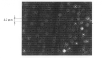
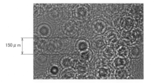
- FIG. 4A is a diagram illustrating an image obtained by observing microbeads with a microscope.
- FIG. 4B is a diagram illustrating an image obtained by observing microbeads through a hologram.
- FIG. 5A is a schematic diagram illustrating a case where an observation target vibrates from side to side.
- FIG. 5B is a schematic diagram illustrating a state where a hologram on the XY plane is viewed.
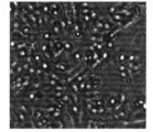
- FIG. 6 is a schematic diagram illustrating a hologram obtained by capturing a cultured cardiac muscle cell by the system of FIG. 1.
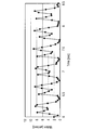
- FIG. 7 is a schematic diagram illustrating a motion analysis result (beat waveform) obtained by performing block matching on the hologram of FIG. 6.
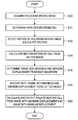
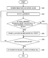
- FIG. 8 is a flowchart illustrating an overall process for detecting a beat area ratio.
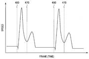
- FIG. 9 is a diagram illustrating FIG. 7 in detail, and it is a characteristic diagram illustrating the maximum and minimum displacements of a beat waveform.
- FIG. 10 is a flowchart illustrating a process for calculating a ratio between a cell with beat and a cell with no beat from an image having maximum displacement and an image having minimum displacement.
- FIG. 10 is a flowchart illustrating a process for calculating a ratio between a cell with beat and a cell with no beat from an image having maximum displacement and an image having minimum displacement.
- FIG. 11 is a schematic diagram illustrating a state where a reconstructed image is segmented into a plurality of blocks, each block including N by N pixels.
- FIG. 12 is a flowchart illustrating a process for calculating the area of a cell in motion from an image having minimum displacement and an image having maximum displacement.
- FIG. 13 is a schematic diagram illustrating how each of the image having minimum displacement and the image having maximum displacement is segmented into a plurality of N-by-N pixel blocks and block matching is performed between the selected blocks.
- FIG. 14 is a flowchart illustrating a process according to a second embodiment.
- FIG. 15 is a schematic diagram illustrating a concentric hologram counted in step S72.
- FIG. 16 is a schematic diagram illustrating a state where only a stationary hologram is extracted in step S76.
- FIG. 17 is a flowchart illustrating an example in which only a cell that is in motion in cells that move randomly individually, such as a sperm, is extracted to reduce calculation load.
- FIG. 18 is a schematic diagram illustrating an image of a concentric hologram.
- FIG. 19 is a schematic diagram illustrating a result obtained by extracting a region of only a hologram that is in motion.
- FIG. 20 is a diagram illustrating an example in which the processing result according to the first embodiment is displayed.
- FIG. 21 is a diagram illustrating an example in which the processing result according to the second embodiment is displayed.
- First Embodiment 1.1 Configuration Example of System 1.2. Process for Detecting Beat Area Ratio 2.
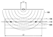
- FIG. 1 is a schematic diagram illustrating the image processing system 1000 according to each of embodiments of the present disclosure, and illustrates a configuration of general lens-free imaging (LFI) system.
- LFI general lens-free imaging
- the light emitted from a light source 100 configured to emit partial coherence light enters an observation target 104 on a sample stage 102.
- the light source 100 is composed of a combination of a laser diode (LD) or LED and a pinhole, as one example, to emit the partial coherence light.
- the observation target 104 is originated in a living body as one example, and an example thereof includes a small organism such as cell, tissue, sperm, fertilized egg, and zebrafish.
- the light incident on the observation target 104 is separated into transmitted light 106 and diffracted light 108.
- the transmitted light 106 interferes with the diffracted light 108 on an image sensor 110 that generates a hologram image output 112.
- the transmitted light 106 can be referred to as reference light for generating a hologram.
- the image processing system 1000 is configured to further include a controller 200, an arithmetic operation unit (image processing device) 300, and an operation input unit 350.
- the controller 200 is used to control the light source 100 and the sensor 110.
- the arithmetic operation unit 300 is used to process the obtained data.
- the operation input unit 350 is used to receive operation information from a user as an input.
- the arithmetic operation unit 300 is composed of a circuit (hardware) or a central processing unit such as CPU and a program (software) for causing it to function.
- the arithmetic operation unit 300 is configured to include a hologram processing unit 302, a reconstruction unit 308, a motion region specifying unit 312, an existence region specifying unit 314, and a display controller 316.
- the hologram processing unit 302 is configured to include a hologram acquisition unit 302a, a motion detector 302b, and a hologram extraction unit 302c.
- the hologram acquisition unit 302a acquires a hologram 400 of the observation target 104 from the sensor 110 through the controller 200.
- the motion detector 302b detects motion of the observation target 104 from the hologram 400.
- the hologram extraction unit 302c extracts a portion of the hologram 400 based on a result obtained by detecting motion of the observation target 104.
- the reconstruction unit 308 reconstructs an image from the extracted hologram 400.
- the motion region specifying unit 312 is configured to include a block matching unit 312a, a ratio calculation unit 312b, and a tracking unit 312c.
- the existence region specifying unit 314 is configured to include a counter.
- the size of a target is set to L1
- the size L2 of the hologram 400 observed on the sensor 110 varies depending on the wavelength of the light source 100 and the distance between the observation target 104 and the sensor 110, resulting in L2 > L1.
- FIG. 3 is a schematic diagram illustrated to describe how to occur the dark part (black circle) and the bright part (white circle) in the interference fringes.
- the bright part (white circle) occurs when wave fronts are aligned constructively
- the dark part (black circle) occurs when wave fronts are destructively shifted by ⁇ /2.
- the solid line and the broken line represent wave fronts having maximum amplitude of a light wave and wave fronts having minimum amplitude of a light wave, respectively.
- the interference fringes can be calculated more accurately using Fresnel-Kirchhoff diffraction formula or Rayleigh-Sommerfeld diffraction formula.
- FIGS. 4A and 4B are diagrams illustrating a comparison between an image and the hologram 400 with a microscope.
- FIG. 4A illustrates an image obtained by observing microbeads with a microscope.
- FIG. 4B illustrates an image (wavelength of 635 nm) obtained by observing microbeads through the hologram 400.
- the size of a microbead is 3.7 ⁇ m, but the size of a microbead observed through the hologram 400 is more than or equal to 150 ⁇ m.
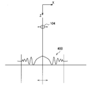
- FIG. 5A illustrates a case where the observation target 104 vibrates from side to side.
- the concentric hologram 400 that is obtained vibrates from side to side, which is similar to the observation target 104.
- the shift amount of the hologram 400 does not differ from the actual shift amount of the observation target 104.
- the shift amount of the observation target 104 can be measured correctly, but the area of a moving object fails to be measured correctly.
- FIG. 5B illustrates the hologram 400 on the XY plane, and represents an output from the sensor 110.
- the motion detector 302b of the hologram processing unit 302 detects motion of the observation target 104 from the hologram 400 using vector analysis.
- an image of the hologram 400 is segmented into a plurality of blocks 450 and the image matching is performed in units of block 450, thereby calculating a motion vector 460.
- the use of the number of the blocks 450 in motion makes it possible to measure the area of the observation target 104 in motion.
- the hologram 400 obtained by capturing the observation target 104 appears to be larger than an actual observation target 104, the hologram 400 will be calculated to have the area larger than the actual observation target 104.
- the correct measurement of the area of the observation target 104 in motion is achieved by reconstructing the observation target 104 from the hologram 400 into the original image, thereby calculating the area from the reconstructed image.
- the reconstruction unit 308 performs a process for reconstructing an image from the hologram 400.
- the reconstruction of an image from the hologram 400 can be performed by lens-free imaging, and uses a technique disclosed in NPL 1 as described above. As one example, when the proportion of those having periodic motion between contraction and relaxation is intended to be calculated from the observation target 104 that exists in the observation field of view, it is possible to calculate correctly the area of a portion in motion by pattern matching if an image having a displacement of 0 and a reconstructed image having maximum displacement are obtained.
- the hologram extraction unit 302c of the hologram processing unit 302 extracts the hologram 400 having a displacement of 0 and the hologram 400 having maximum displacement
- the reconstruction unit 308 reconstructs only the extracted hologram 400.
- the reconstruction of only the image having a displacement of 0 and the image having maximum displacement can reduce the computation time significantly, as compared with the case where all the frames are reconstructed.
- FIG. 6 is a schematic diagram illustrating the hologram 400 obtained by capturing the cultured cardiac muscle cell by the image processing system 1000, and the hologram 400 is not reconstructed.
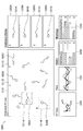
- FIG. 7 is a schematic diagram illustrating a motion analysis result (beat waveform) obtained by performing the block matching on the hologram 400.
- the horizontal axis represents time
- the vertical axis represents speed.
- the motion analysis shown in FIG. 7 can be acquired by calculating a motion vector for each block on the frame image data at the current time and the frame image data at the immediately previous time, and it can be acquired using the method disclosed in PTL 1, as one example.
- the value of speed shown in FIG. 7 indicates an average of the obtained motion vectors. As illustrated in FIG. 7, two periodic sets of peaks are observed in the waveform of the speed, that is, the first peak indicates contraction, and the second peak indicates relaxation. A portion corresponding to a valley between contraction and relaxation indicates the maximum displacement point of the beat.
- FIG. 8 is a flowchart illustrating an overall process for detecting a beat area ratio.
- FIG. 9 is a diagram illustrating FIG. 7 in more detail, and it is a characteristic diagram illustrating positions of the maximum displacement 470 and minimum displacement 480 in the beat waveform.
- step S10 a moving image of the hologram 400 is acquired.
- step S11 the area of the hologram 400 derived from a cell is determined based on a threshold of the contrast.
- a region where a cell exists is specified.
- the beat waveform may be calculated from the whole screen without specifying a region where a cell exists.
- step S12 a motion vector is detected from the moving image of the hologram 400.
- the detection of the motion vector of only the cell-derived region that is determined in step S11 makes it possible to reduce the processing load.
- the region where a cell exists may be determined based on the number of blocks having a luminance difference that is more than or equal to a predetermined value, which is similar to a process in FIG. 10 described later.
- step S14 the beat waveform of a cell is calculated from an image of the motion vector.
- step S16 a frame of the maximum displacement 470 and minimum displacement 480 in the beat waveform is determined from the beat waveform. As illustrated in FIG. 9, a cell appears to be larger from the minimum displacement 480 and then is the largest at the maximum displacement 470. Next, the cell contracts and then is the smallest at the next minimum displacement 480. Then, in step S18, the frame of the maximum displacement 470 and minimum displacement 480 is reconstructed using the LFI technique. This allows an image having maximum displacement to be obtained from the frame of the maximum displacement 470 and allows an image having minimum displacement to be obtained from the frame of the minimum displacement 480. Then, in step S20, the ratio (area ratio) of a beating cell is calculated from the image having maximum displacement and the image having minimum displacement and is outputted.
- FIG. 10 is a flowchart illustrating a process for calculating the area in which a cell exists from an image cell of the minimum displacement or the maximum displacement to exclude a planar area in which there is no cell from the calculation.
- the area A is calculated by counting the number of blocks having a luminance difference that is more than or equal to a predetermined threshold among blocks of the reconstructed image.
- the calculation of area is performed by the existence region specifying unit 314.
- the area A can be calculated from any one or both of the image having maximum displacement and the image having minimum displacement.
- a region where a cell exists may be specified based on user operation information inputted to the operation input unit 350. It is possible for the user to specify a region where a cell exists by specifying a region in a screen based on the screen displayed on a display unit by the display controller 316.
- step S30 a block 450 of N by N pixels is sequentially extracted from a reconstructed image, and thus the reconstructed image is segmented into each block 450 of N by N pixels.
- FIG. 11 illustrates a state where the entire reconstructed image is segmented into a plurality of blocks, and each block contains N by N pixels.
- step S32 the (i, j)-th block is selected.
- step S34 determination of whether there is a luminance difference more than or equal to a predetermined threshold in the block selected in step S32 is performed.
- FIG. 11 illustrates a state where one of N-by-N pixel blocks is extracted, and the luminance of each pixel in the extracted block is represented by concentration. As one example, when a luminance value is represented by eight bits, the luminance of each pixel can be represented by 255 levels. The maximum luminance difference is obtained, and in step S34, the determination of whether the maximum luminance difference is more than or equal to a predetermined threshold is performed.
- step S34 if there is a luminance difference that is more than or equal to a predetermined threshold in the block, the process proceeds to step S36.
- a luminance difference that is more than or equal to a predetermined threshold in the block it is determined that the block corresponds to the position of a cell.
- the block has a uniform luminance, such as white or black, it is determined that the block is a region that does not correspond to a cell.
- step S36 the (i, j)-th block is counted as an area in which a cell exists. This counting is performed by the counter of the existence region specifying unit 314. After step S36, the process proceeds to step S38. Alternatively, if it is determined in step S34 that the luminance difference in the block is less than the predetermined threshold, the process proceeds to step S38.
- step S38 a determination of whether all the blocks are evaluated is performed, and if all the blocks are evaluated, then the process proceeds to step S40.
- step S40 the finally counted number of blocks is set to the whole cell. On the other hand, not all the blocks are evaluated in step S38, the process returns to step S32 and the subsequent block is selected.
- the area A of the area in which a cell exists is calculated from the number of blocks in which the luminance difference is more than or equal to a predetermined threshold in the process of FIG. 10, an area in which a cell exists and an area in which there is no cell are detected, the area in the closed edge may be set to the area A of an area in which a cell exists.
- FIG. 12 is a flowchart illustrating a process for calculating the area of a cell in motion from the image having minimum displacement and the image having maximum displacement.
- the image having minimum displacement and the image having maximum displacement are subject to a similar process.
- step S50 a block of N by N pixels is extracted from each of the image having minimum displacement and the image having maximum displacement, which is similar to step S30 of FIG. 10, and thus each image is segmented into N-by-N pixel blocks.
- step S52 the (i, J)-th block is selected for each of the images.
- step S54 a determination of whether the block selected in step S52 is included in the region of the area A calculated by the flowchart of FIG. 10 is performed, and if it is included in the region of the area A, then the process proceeds to step S56.
- step S56 the matching is performed between the selected blocks of the image having minimum displacement and the image having maximum displacement.
- This block matching is performed by the block matching unit 312a of the motion region specifying unit 312.
- FIG. 13 illustrates how each of the image having minimum displacement and the image having maximum displacement is segmented into a plurality of N-by-N pixel blocks and the block matching is performed between blocks whose positions correspond to each other.
- the block matching is evaluated based on a parameter indicating a level in which the two blocks match. If the parameter is more than or equal to a predetermined threshold, then the two blocks are determined to match.
- FIG. 13 illustrates a case where the process of FIG. 10 described above is performed based on the image having minimum displacement and the area A is calculated in the image having minimum displacement.
- step S56 when the two blocks match, the process proceeds to step S58.
- step S60 the (i, j)-th block is counted as an area in which a moving cell exists, then the process proceeds to step S58.
- step S54 it is determined in step S54 that a block selected in step S52 is not included in a region of the area A, the process proceeds to step S58.
- step S56 the block is counted as an area in which a moving cell exists and the area (motion region) of the area in which a moving cell exists is extracted depending on the number of counts. This process is performed by the motion region specifying unit 312.
- step S58 a determination of whether all the blocks are evaluated is performed, and if all the blocks are evaluated, then the process proceeds to step S62.
- step S62 the final total number of blocks counted in step S60 is set to an area B of a cell in motion.
- the process returns to step S52 and the subsequent block is selected.
- the block matching between the image having minimum displacement and the image having maximum displacement makes it possible to determine the area B of the area in which a moving cell exists and to calculate the ratio of the area B of the area in which a moving cell exists to the area A of the area in which a cell exists.
- a difference is obtained by subtracting between corresponding pixel values (luminance values) of the image having minimum displacement and the image having maximum displacement, and the area may be calculated from the number of peaks in which the difference exceeds a certain threshold.
- the ratio of the area B of the area in which a moving cell exists to the area A of the area in which a cell exists is a parameter indicating a ratio of cardiac muscle cells with beat of cells within the observation field of view.
- the area B of the area in which a moving cell exists is less than the area A of the area in which a cell exists, and thus the relationship of area B ⁇ area A is established.
- the reconstruction is performed by extracting only the frame of the image having minimum displacement and the image having maximum displacement from the frame of a moving image of the hologram 400 in the process described above, this is possible as long as there is a change in differences detectable from the extracted frame even for other frames than the frame of the image having minimum displacement and the image having maximum displacement.
- this is possible depending on the purpose, for example, by extracting a frame in which irregular beat occurs.
- the temporal variation of the hologram 400 is limited to a portion of the screen, it is not necessary for the entire image of the hologram 400 to be reconstructed, and thus, an area of the image to be reconstructed may be limited. It is possible to reconstruct only a region where the temporal variation occurs in the image, thereby simplifying the process.
- the beat involves propagation particularly in the cardiac muscle image, and thus the image having maximum displacement is not necessarily obtained in the entire screen.
- the cardiac muscle cells are not concentrated, sometimes the synchronization of beat may be insufficient.
- the motion waveform may be calculated by segmenting an image of the hologram 400 into a plurality of areas and performing the analysis of motion in each area. In this case, the frames of the extracted image having minimum displacement and image having maximum displacement are different for each of the segmented areas.
- the motion analysis is performed based on the hologram 400 of the frames of the moving image of the hologram 400, and only the image having minimum displacement and the image having maximum displacement that are obtained by the motion analysis are reconstructed.
- the ratio of the area B of the area in which a moving cell exists to the area A of the area in which a cell exists is determined based on the reconstructed image having minimum displacement and image having maximum displacement.
- the reconstruction of only the image having minimum displacement and the image having maximum displacement allows the processing load to be reduced significantly. This makes it possible to acquire the proportion of a beating cell of the cells in the observation field of view.
- Second Embodiment 2.1 Example of Observation of Cell having Random Motion
- An image processing system according to the second embodiment is similar to the first embodiment.
- the present disclosure is applied to not a cell having periodic motion such as cardiac muscle cells but other cells including a cell having random motion will be described.
- the motion of a cell is not periodic, and thus it is assumed a case where the maximum amount of displacement fails to be calculated from the result obtained by analyzing the motion of the hologram 400.
- the extraction of a frame is performed as follows.
- the graph of the amount of motion is planar at normal times and the sperm head is observed as the ring-shaped hologram 400, thus it is possible to obtain a desired parameter, such as the number cells and motility, by tracking the interference ring or by analyzing the motion.
- a desired parameter such as the number cells and motility
- the hologram 400 corresponding to only one frame is reconstructed and scratch or dust is removed, thereby detecting the exact number of cells.
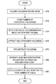
- FIG. 14 is a flowchart illustrating a process according to the second embodiment, and illustrates an example of using the reconstructed image to separate scratch or dust and of using a hologram to count cells.
- step S70 the moving image of the hologram 400 is acquired.
- step S72 the number of concentric holograms (ring-shaped holograms) is counted.
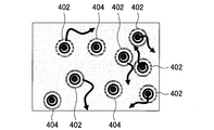
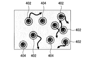
- FIG. 15 illustrates concentric holograms 402 and 404 counted in step S72.
- the hologram 402 is in motion, but the hologram 404 is not in motion.
- step S74 the motion of the moving image of the hologram is detected, and the tracking is performed.
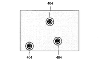
- step S76 only a stationary hologram 404 is extracted.
- FIG. 16 is a schematic diagram illustrating a state where only the stationary hologram 404 is extracted in step S76.
- step S78 the hologram 404 extracted in step S76 is reconstructed. If the reconstructed image is obtained, it is possible to recognize whether the ring-shaped hologram contains dust or scratch.
- step S80 the dust or scratch is separated from the reconstructed image, and the resultant value is excluded from the number of counts of the hologram 404 that is not in motion.
- step S82 the ratio of the number of cells that is in motion to the total number of cells is calculated.
- step S82 the ratio of the number of the hologram 402 to the total number of the holograms 402 and 404 is determined. The calculation of the ratio is performed by the ratio calculation unit 312b of the motion region specifying unit 312.
- the process of FIG. 14 allows only the hologram 404 that is stationary to be extracted and reconstructed, and thus it is possible to separate dust or scratch and to count exactly the number of cells that are stationary. Thus, it is possible to calculate the ratio of the number of cells that is in motion to the total number of cells with high accuracy.
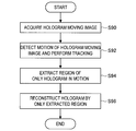
- FIG. 17 is a flowchart illustrating an example in which only a cell that is in motion in the cells that move randomly individually, such as a sperm, is extracted to reduce the calculation load.
- step S90 a moving image of a hologram is acquired.
- step S92 a motion of the moving image of the hologram is detected and the tracking is performed.
- step S94 a region of only the hologram 402 that is in motion is extracted. The extraction of the region is performed by the hologram extraction unit 302c of the hologram processing unit 302.
- FIG. 17 is a flowchart illustrating an example in which only a cell that is in motion in the cells that move randomly individually, such as a sperm, is extracted to reduce the calculation load.
- step S96 the hologram 402 is reconstructed by only the region extracted in step S94. After step S96, the process ends.
- the process of FIG. 17 allows the region of only the hologram 402 that is in motion to be extracted and the reconstruction of the hologram 402 is performed, thereby reducing the calculation load significantly.
- FIG. 20 is a diagram illustrating an example in which the processing result according to the first embodiment is displayed.
- a screen 1100 displayed on the display unit by the display controller 316 includes an original moving image displaying screen 1110, a cell existence region displaying screen 1120A, and a cell motion region displaying screen 1120B.
- the original moving image displaying screen 1110 displays a hologram image of a plurality of cardiac muscle cells.
- a cardiac muscle cell image 510A is an observation target using the hologram 400.
- the arithmetic operation unit 300 performs a motion analysis process on the hologram 400 of the cardiac muscle cell image 510A.
- an image 511A obtained by reconstructing the hologram 400 of the cardiac muscle cell image 510A is displayed.
- a region where a cell exists (area A) is displayed.
- the cell motion region displaying screen 1120B displays a region 511B in which a cell is in motion in the area A in addition to the image 511A corresponding to the area A displayed on the cell existence region displaying screen 1120A.
- An analysis result displaying screen 1130 displays a graph showing the movement history of the cardiac muscle cell image 510A.
- the movement history can be acquired from a motion compensation parameter of a translational component for the cardiac muscle cell image 510A. This makes it possible to evaluate quantitatively a motion in the translation direction of the cardiac muscle cell.
- FIG. 21 is a diagram illustrating an example in which the processing result according to the second embodiment is displayed.
- a screen 1200 displayed on the display unit by the display controller 316 includes an original moving image displaying screen 1210, reconstructed image displaying screens 1220A to 1220D, and an analysis result displaying screens 1230 to 1233.
- the original moving image displaying screen 1210 displays a hologram image of a plurality of sperms.
- sperm images 520A to 520D are selected as a target to be processed in the processing unit 260 by the user's operation or the like.
- frames 1211A to 1211D indicating that the sperm images 520A to 520D are selected may be displayed around the sperm images 520A to 520D, respectively.
- the arithmetic operation unit 300 performs on each of the selected sperm images 520A to 520D.
- the reconstructed image displaying screens 1220A to 1220D moving images including sperm images 521A to 521D obtained by reconstructing the hologram are displayed, respectively.
- the display controller 316 may control the direction or the like of each of the reconstructed images so that the sperm images 521A to 521D are the same direction.
- a graph showing the movement history and a graph showing the rotation history of the sperm images 520A to 520D are displayed respectively.
- the movement history can be acquired from a motion compensation parameter of a translational component for the sperm images 520A to 520D.
- the rotation history can be acquired from a motion compensation parameter of a rotational component for the sperm images 520A to 520D.
- a bar graph showing the amount of movement of the sperm images 520A to 520D is displayed.
- the amount of movement can be acquired from a motion compensation parameter of a translational component for the sperm images 520A to 520D. It is possible to evaluate quantitatively a motion state of the sperm by displaying the amount of movement of each sperm using the bar graph.
- An image processing apparatus including: a motion detector configured to detect motion of an observation target from a hologram of the observation target; a hologram processing unit configured to extract a portion of the hologram based on a result obtained by detecting the motion of the observation target; and a reconstruction unit configured to reconstruct an image from a portion of the extracted hologram.
- the hologram includes a plurality of frames acquired at different points in time, and the hologram processing unit extracts a portion from the plurality of frames based on the detection result.
- the image processing apparatus further including: a block matching unit configured to determine whether a first image block in the frame having the maximum amount of displacement matches a second image block in the frame having the minimum amount of displacement, the second image block corresponding, in position, to the first image block; a motion region specifying unit configured to, when the first image block and the second image block fail to match based on the determination result, specify a region corresponding to the first image block and the second image block as a motion region of the observation target; and a ratio calculation unit configured to calculate a ratio of the motion region to a region in which the observation target exists.
- the image processing apparatus further including: an existence region specifying unit configured to specify the region in which the observation target exists based on a luminance difference in the first image block or the second image block.
- an existence region extracting unit configured to specify the region in which the observation target exists based on user operation information.
- the hologram processing unit extracts a portion of a planar region of the hologram based on the detection result.
- the image processing apparatus according to any one of (1) to (10), wherein the observation target is an object derived from a living body.
- a method of image processing including: detecting motion of an observation target from a hologram of the observation target; extracting a portion of the hologram based on a result obtained by detecting the motion of the observation target; and reconstructing an image from a portion of the extracted hologram.
- An image processing system including: a light source configured to emit partial coherence light to an observation target; an image sensor configured to detect a hologram by interference between transmitted light and diffracted light obtained by separating the partial coherence light by the observation target; a motion detector configured to detect motion of the observation target from the hologram; a hologram processing unit configured to extract a portion of the hologram based on a result obtained by detecting the motion of the observation target; and a reconstruction unit configured to reconstruct an image from a portion of the extracted hologram.
Landscapes
- Engineering & Computer Science (AREA)
- Physics & Mathematics (AREA)
- General Physics & Mathematics (AREA)
- Theoretical Computer Science (AREA)
- Computer Vision & Pattern Recognition (AREA)
- Multimedia (AREA)
- Chemical & Material Sciences (AREA)
- Computer Graphics (AREA)
- Software Systems (AREA)
- General Engineering & Computer Science (AREA)
- Computer Hardware Design (AREA)
- Computing Systems (AREA)
- Architecture (AREA)
- Signal Processing (AREA)
- Dispersion Chemistry (AREA)
- Health & Medical Sciences (AREA)
- Life Sciences & Earth Sciences (AREA)
- Analytical Chemistry (AREA)
- Biochemistry (AREA)
- General Health & Medical Sciences (AREA)
- Immunology (AREA)
- Pathology (AREA)
- Investigating Or Analysing Materials By Optical Means (AREA)
- Holo Graphy (AREA)
- Image Analysis (AREA)
- Length Measuring Devices By Optical Means (AREA)
- Image Processing (AREA)
Priority Applications (2)
| Application Number | Priority Date | Filing Date | Title |
|---|---|---|---|
| US16/073,500 US10852695B2 (en) | 2016-02-16 | 2017-02-03 | Image processing apparatus, method of image processing, and image processing system |
| DE112017000840.9T DE112017000840T5 (de) | 2016-02-16 | 2017-02-03 | Bildverarbeitungsvorrichtung, verfahren zur bildverarbeitung und bildverarbeitungssystem |
Applications Claiming Priority (2)
| Application Number | Priority Date | Filing Date | Title |
|---|---|---|---|
| JP2016-026758 | 2016-02-16 | ||
| JP2016026758A JP2017146696A (ja) | 2016-02-16 | 2016-02-16 | 画像処理装置、画像処理方法及び画像処理システム |
Publications (1)
| Publication Number | Publication Date |
|---|---|
| WO2017141741A1 true WO2017141741A1 (en) | 2017-08-24 |
Family
ID=58185582
Family Applications (1)
| Application Number | Title | Priority Date | Filing Date |
|---|---|---|---|
| PCT/JP2017/004088 Ceased WO2017141741A1 (en) | 2016-02-16 | 2017-02-03 | Image processing apparatus, method of image processing, and image processing system |
Country Status (4)
| Country | Link |
|---|---|
| US (1) | US10852695B2 (enExample) |
| JP (1) | JP2017146696A (enExample) |
| DE (1) | DE112017000840T5 (enExample) |
| WO (1) | WO2017141741A1 (enExample) |
Families Citing this family (6)
| Publication number | Priority date | Publication date | Assignee | Title |
|---|---|---|---|---|
| JP2020046308A (ja) * | 2018-09-19 | 2020-03-26 | ソニー株式会社 | 観察装置、観察方法及び観察システム |
| EP4175283A4 (en) * | 2020-06-25 | 2023-11-22 | FUJIFILM Corporation | INFORMATION PROCESSING DEVICE, ASSOCIATED OPERATING METHOD AND OPERATING PROGRAM |
| CN112514831B (zh) * | 2020-07-28 | 2022-06-10 | 上海市农业科学院 | 一种活体鳝鱼表型获取的装置与方法 |
| JPWO2023195490A1 (enExample) * | 2022-04-06 | 2023-10-12 | ||
| CN118883551B (zh) * | 2024-09-27 | 2024-12-03 | 季华实验室 | 精子自动检测系统及其控制方法 |
| CN120403491B (zh) * | 2025-07-02 | 2025-10-24 | 浙江农林大学 | 基于双目结构光的鸡蛋蛋形指数提取方法及其系统 |
Citations (5)
| Publication number | Priority date | Publication date | Assignee | Title |
|---|---|---|---|---|
| US20120148141A1 (en) * | 2010-12-14 | 2012-06-14 | Aydogan Ozcan | Compact automated semen analysis platform using lens-free on-chip microscopy |
| WO2015008682A1 (ja) * | 2013-07-19 | 2015-01-22 | ソニー株式会社 | 細胞評価装置および方法、並びにプログラム |
| US20150204773A1 (en) * | 2012-07-13 | 2015-07-23 | The Regents Of The University Of Califronia | High throughput lens-free three-dimensional tracking of sperm |
| JP5772817B2 (ja) | 2010-03-29 | 2015-09-02 | ソニー株式会社 | 画像処理装置および方法、並びに、プログラム |
| WO2015150589A1 (en) * | 2014-04-03 | 2015-10-08 | Imec Vzw | Method and device for drug screening |
Family Cites Families (4)
| Publication number | Priority date | Publication date | Assignee | Title |
|---|---|---|---|---|
| JP5216761B2 (ja) * | 2007-09-26 | 2013-06-19 | パナソニック株式会社 | ビーム走査型表示装置 |
| WO2011149525A1 (en) * | 2010-05-25 | 2011-12-01 | Arryx, Inc. | Holographic fluctuation microscopy apparatus and method for determining mobility of particle and/or cell dispersions |
| KR20170029320A (ko) * | 2015-09-07 | 2017-03-15 | 엘지전자 주식회사 | 이동 단말기 및 그 제어방법 |
| JP6046789B2 (ja) | 2015-10-27 | 2016-12-21 | 京楽産業.株式会社 | 遊技機 |
-
2016
- 2016-02-16 JP JP2016026758A patent/JP2017146696A/ja active Pending
-
2017
- 2017-02-03 US US16/073,500 patent/US10852695B2/en active Active
- 2017-02-03 WO PCT/JP2017/004088 patent/WO2017141741A1/en not_active Ceased
- 2017-02-03 DE DE112017000840.9T patent/DE112017000840T5/de not_active Withdrawn
Patent Citations (5)
| Publication number | Priority date | Publication date | Assignee | Title |
|---|---|---|---|---|
| JP5772817B2 (ja) | 2010-03-29 | 2015-09-02 | ソニー株式会社 | 画像処理装置および方法、並びに、プログラム |
| US20120148141A1 (en) * | 2010-12-14 | 2012-06-14 | Aydogan Ozcan | Compact automated semen analysis platform using lens-free on-chip microscopy |
| US20150204773A1 (en) * | 2012-07-13 | 2015-07-23 | The Regents Of The University Of Califronia | High throughput lens-free three-dimensional tracking of sperm |
| WO2015008682A1 (ja) * | 2013-07-19 | 2015-01-22 | ソニー株式会社 | 細胞評価装置および方法、並びにプログラム |
| WO2015150589A1 (en) * | 2014-04-03 | 2015-10-08 | Imec Vzw | Method and device for drug screening |
Non-Patent Citations (2)
| Title |
|---|
| ONUR MUDANYALI; DEREK TSENG; CHULWOO OH; SERHAN O. ISIKMAN; IKBAL SENCAN; WAHEB BISHARA; CETIN OZTOPRAK; SUNGKYU SEO; BAHAR KHADEM, COMPACT, LIGHT-WEIGHT AND COST-EFFECTIVE MICROSCOPE BASED ON LENSLESS INCOHERENT HOLOGRAPHY FOR TELEMEDICINE APPLICATIONS, Retrieved from the Internet <URL:www.rsc.org/loc> |
| SANG BOK KIM ET AL: "A cell-based biosensor for real-time detection of cardiotoxicity using lensfree imaging", LAB ON A CHIP, vol. 11, no. 10, 11 April 2011 (2011-04-11), pages 1801 - 1807, XP055194342, ISSN: 1473-0197, DOI: 10.1039/c1lc20098d * |
Also Published As
| Publication number | Publication date |
|---|---|
| JP2017146696A (ja) | 2017-08-24 |
| US10852695B2 (en) | 2020-12-01 |
| US20190049897A1 (en) | 2019-02-14 |
| DE112017000840T5 (de) | 2018-11-22 |
Similar Documents
| Publication | Publication Date | Title |
|---|---|---|
| WO2017141741A1 (en) | Image processing apparatus, method of image processing, and image processing system | |
| US8477996B2 (en) | Method and device for finding and tracking pairs of eyes | |
| JP2014029287A (ja) | 壊死細胞領域検出装置及びその方法、壊死細胞領域検出プログラム | |
| CN110274877A (zh) | 一种基于散射介质的3d光谱成像系统及方法 | |
| RU2015155611A (ru) | Аппарат для оптической когерентной томографии (окт) глаза и способ оптической когерентной томографии (окт) глаза | |
| Wang et al. | Pattern recognition and classification of two cancer cell lines by diffraction imaging at multiple pixel distances | |
| EP3416366B1 (en) | Image pickup apparatus and image pickup method | |
| JP7174604B2 (ja) | 光画像計測装置、光画像計測方法 | |
| EP4535292A1 (en) | OPTICAL IMPLEMENTATION OF MACHINE LEARNING FOR REAL TIME INCREASED CONTRAST VIA MULTIPLE WAVELENGTH lLLUMINATION WITH TUNABLE POWER | |
| Goud et al. | Low cost digital holographic microscope for 3-D cell imaging by integrating smartphone and DVD optical head | |
| US9581429B2 (en) | Method and system for reconstructing optical properties of diffracting objects immersed in a liquid medium | |
| Koniar et al. | Segmentation of motion regions for biomechanical systems | |
| Li et al. | Flexible and universal autofocus based on amplitude difference of fractional Fourier transform | |
| CN112396622A (zh) | 基于多维特征空间的微血流图像分割量化方法和系统 | |
| US20110242543A1 (en) | Interferometric systems having reflective chambers and related methods | |
| FI131423B1 (en) | Eye tracking lighting | |
| KR20230053847A (ko) | 푸리에 타이코그래피 현미경 및 그 사용 방법 | |
| Taori et al. | Segmentation of macula in retinal images using automated seeding region growing technique | |
| Romero et al. | Digital holographic microscopy for detection of Trypanosoma cruzi parasites in fresh blood mounts | |
| Johnston et al. | Induced motion at texture–defined motion boundaries | |
| US20240264423A1 (en) | High throughput lensless imaging method and system thereof | |
| US12169271B2 (en) | Method for evaluating measurement data from a light field microscope, and apparatus for light field microscopy | |
| Borrelli et al. | 3D Holographic Flow Cytometry Measurements of Microalgae: Strategies for Angle Recovery in Complex Rotation Patterns | |
| US20210191316A1 (en) | Lensfree method for imaging biological samples in three dimensions | |
| Yamazaki et al. | A cabled observatory system for integrated long term, high-frequency biological, chemical, physical measurement for understanding planktonic ecosystem |
Legal Events
| Date | Code | Title | Description |
|---|---|---|---|
| 121 | Ep: the epo has been informed by wipo that ep was designated in this application |
Ref document number: 17707689 Country of ref document: EP Kind code of ref document: A1 |
|
| 122 | Ep: pct application non-entry in european phase |
Ref document number: 17707689 Country of ref document: EP Kind code of ref document: A1 |