WO2017141589A1 - 車両制御装置 - Google Patents
車両制御装置 Download PDFInfo
- Publication number
- WO2017141589A1 WO2017141589A1 PCT/JP2017/000910 JP2017000910W WO2017141589A1 WO 2017141589 A1 WO2017141589 A1 WO 2017141589A1 JP 2017000910 W JP2017000910 W JP 2017000910W WO 2017141589 A1 WO2017141589 A1 WO 2017141589A1
- Authority
- WO
- WIPO (PCT)
- Prior art keywords
- event sequence
- event
- unknown
- unit
- sequence
- Prior art date
- Legal status (The legal status is an assumption and is not a legal conclusion. Google has not performed a legal analysis and makes no representation as to the accuracy of the status listed.)
- Ceased
Links
Images






Classifications
-
- B—PERFORMING OPERATIONS; TRANSPORTING
- B60—VEHICLES IN GENERAL
- B60R—VEHICLES, VEHICLE FITTINGS, OR VEHICLE PARTS, NOT OTHERWISE PROVIDED FOR
- B60R16/00—Electric or fluid circuits specially adapted for vehicles and not otherwise provided for; Arrangement of elements of electric or fluid circuits specially adapted for vehicles and not otherwise provided for
- B60R16/02—Electric or fluid circuits specially adapted for vehicles and not otherwise provided for; Arrangement of elements of electric or fluid circuits specially adapted for vehicles and not otherwise provided for electric constitutive elements
-
- G—PHYSICS
- G06—COMPUTING OR CALCULATING; COUNTING
- G06F—ELECTRIC DIGITAL DATA PROCESSING
- G06F11/00—Error detection; Error correction; Monitoring
- G06F11/07—Responding to the occurrence of a fault, e.g. fault tolerance
-
- G—PHYSICS
- G06—COMPUTING OR CALCULATING; COUNTING
- G06F—ELECTRIC DIGITAL DATA PROCESSING
- G06F11/00—Error detection; Error correction; Monitoring
- G06F11/36—Prevention of errors by analysis, debugging or testing of software
Definitions
- the present invention relates to a vehicle control device for an automobile.
- JP 2010-267207 A Patent Document 1
- This gazette has the problem of “how much the observation data deviates from the reference pattern, that is, how much extraordinary data it is, even if the specificity of the observation data can be determined”
- a non-dailyness evaluation device that can evaluate to what extent the event data series obtained by the user's behavior is not normal with respect to the reference pattern representing the daily behavior of the user, Provide daily life evaluation method and computer program ".
- the object of the present invention is to make it possible to collect data that can analyze defects that have not been revealed.
- the present invention includes an event sequence generation unit that generates an event sequence including one or a plurality of events based on an output result output from a monitoring target, a known event sequence storage unit that stores a known event sequence in advance, An event sequence comparison unit that compares the event sequence generated by the event sequence generation unit with the known event sequence, and an unknown event sequence that does not match the known event sequence is extracted from the generated event sequence A reporting section for reporting.
- a vehicle control device capable of collecting data capable of analyzing a problem that has not been revealed.
- 1 is a vehicle control system according to a first embodiment.
- 1 is an ECU according to a first embodiment.
- 2 is a software structure according to the first embodiment.
- 2 is a configuration of a log collection unit according to the first embodiment.
- 3 is a configuration of an event string generation unit of the log collection unit according to the first embodiment.
- 3 is a data string used for event string generation according to the first embodiment. This is a generation condition used for event sequence generation in the first embodiment.
- 3 is an event sequence according to the first embodiment.
- 4 is a known event sequence according to the first embodiment.
- 6 is a configuration of a log collection unit according to the second embodiment.
- 10 is a report event string according to the second embodiment. 10 illustrates a configuration of a log collection unit according to a third embodiment. 12 is an unknown event sequence table according to the third embodiment. 10 is a report event string according to the fourth embodiment. This is the configuration in the fourth embodiment. This is the configuration in the fifth embodiment.
- the present embodiment mainly describes a vehicle control system in a vehicle system, which is suitable for implementation in a vehicle system, but does not prevent application to other than the vehicle system.
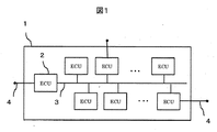
- FIG. 1 shows a system configuration using a vehicle control device included in the vehicle control system of the present embodiment.
- the vehicle control system 1 includes an in-vehicle network 3 (CAN: Controller Area Network, CAN FD: CAN with Flexible Data-rate, Ethernet (registered trademark), etc.) to which a plurality of ECUs (Electronic Control Units) 2 are connected. Is done.
- the in-vehicle network 3 is connected to a network outside the vehicle control system through an external communication path 4 (for example, communication using a protocol such as mobile phone communication, wireless LAN, WAN, etc.), and the information calculated by the ECU 2 is stored outside the vehicle. Or data outside the vehicle can be received and notified to the in-vehicle network 3.
- CAN Controller Area Network
- CAN FD CAN with Flexible Data-rate, Ethernet (registered trademark), etc.
- ECUs Electronic Control Units
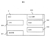
- FIG. 2 shows the configuration of the ECU 2.
- the ECU 2 includes a communication device 201 connected to the in-vehicle network 3, a ROM (Read Only Memory) 202 that stores programs and nonvolatile data, a RAM (Random Access Memory) 203 that stores volatile data, An observation value is acquired from a data transmission / reception, a sensor, or the like with respect to a processor 204 such as a CPU having a storage element such as a cache and a register and executing control, and a driving device or / and a recognition device 6 connected by a dedicated line.
- An input / output device 205 is used.
- the application 501 is a software module that exists in one or more software.
- the application 501 is calculated by vehicle control component software, such as the amount of control of the driving device, the processing of information obtained from the sensor, the calculation of the driver's operation amount estimated from the information obtained from the sensor, and the failure diagnosis. Calculate the function to be. Data is exchanged between applications, and data exchange via the RTE 502 and the in-vehicle network 3 and data exchange between applications are performed.
- An RTE (Run Time Environment) 502 provides an interface for data transmission / reception to the application 501.
- the application 501 transmits and receives data without depending on the BSW 504 depending on the configuration of the ECU 2 by transmitting and receiving data using the RTE.
- the RTE 502 does not need to exist in software, and in this case, each application needs to program data transmission / reception according to the data transmission / reception destination module.
- the BSW 503 is a software unit that implements functions depending on the hardware configuration of the ECU 2. For example, a current value obtained from an operating system, communication software, and various input / output devices corresponds to BSW.
- the log collection unit 6 is a kind of application 501.
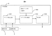
- FIG. 4 shows the structure of the log collection unit 6.
- the event string generation unit 601 converts a data string described later into an event string described later according to a rule described later.
- An event sequence is a collection of a plurality of events.
- the event string generation unit 601 obtains data from a monitoring target X described later and configures a data string.
- the known event sequence storage unit 602 stores in advance normal known event sequences collected in advance.
- the event sequence comparison unit 603 compares the known event sequence stored in the known event sequence with the event sequence configured by the event sequence generation unit 601, determines whether the obtained event sequence is known, and outputs the determination result To do.
- the reporting unit 604 outputs the determination result obtained from the event sequence comparison unit and the event sequence used for the determination as the output of the log collection unit. Specifically, the report unit 604 extracts and reports an unknown event sequence that does not match the known event sequence from the generated event sequence.
- the unknown event sequence is an event sequence that is not registered in advance in the known event sequence storage unit 602.
- the monitoring target applies to those that calculate data that can constitute a data string to be described later, such as an application 501 and BSW 503 in the same ECU, a different ECU, a driving device such as a motor, and a sensor connected to the input / output device 205.
- FIG. 7 shows the structure of the event sequence generator 601.
- the event sequence generation unit 601 includes a data acquisition unit 6011, an event generation unit 6012, and an event sequence configuration unit 6013.
- the data acquisition unit 6011 acquires data obtained from the monitoring target X and configures a data string to be described later.
- the event generation unit 6012 generates an event described later in light of an event generation condition described later.
- the event sequence configuration unit 6013 forms the event configured by the event generation unit 6012 in an event sequence format to be described later.
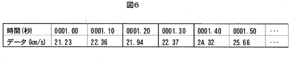
- FIG. 6 shows an example of the data string.
- Data constituting the data string indicates values calculated and acquired by the control device such as application calculation results, sensor data, BSW and OS states, processor commands, and time information.
- the data string represents a data string in which the obtained data is arranged in time series or in the order received.
- FIG. 7 shows an example of an event sequence.
- the event constituting the event string represents information when the data constituting the data string is changed.
- the data changes here, for example, when the speed of the vehicle body acquired by the sensor starts to decrease from a certain value, “the speed has started to decrease” becomes an event.
- an event ID representing “the speed has started to decrease” is obtained.
- an event ID representing “initialization start” is obtained.
- the driver depresses the brake pedal it is detected that the amount of depression of the brake pedal has exceeded a certain level, and an event ID “with brake depressing” is obtained.
- events can acquire flag changes as events. For example, when the continuous operation time of the motor becomes abnormal for a certain period of time, there is an event ID indicating that there is control for limiting the operation of the motor so that it does not become too high, such as “continuous operation time constant or more”. As another example, an event ID indicating “ACC flag ON” is obtained by acquiring information that the driver has turned on an ACC (Accel Cruise Control) switch.
- ACC Accelel Cruise Control
- an event refers to the change content of a single control value, for example.
- the event ID is expressed by a value that can uniquely identify the event. For example, it can be expressed using numbers or by using a plurality of alphabets.
- the event string generation unit extracts data related to each event ID from the data string and determines an event.
- the data string may collect data individually for each event, or may collect a plurality of data related to a plurality of events at the same time.
- FIG. 3 shows an example of a data string.
- ⁇ Data may be a physical value other than speed or a continuous numerical value such as a counter. Further, when collecting different variables expressing the same physical value, a data string may be collected for each variable.
- Hours can be expressed in units such as seconds, minutes, or hours. Time may be expressed not only as an integer but also as a small number. In addition, time information such as seconds, minutes, and hours can be expressed as an absolute time that represents the date and time when the data is acquired, or a relative time from the acquisition time of the reference data. For example, data that can be periodically acquired, such as every 10 ms, may be expressed not in time information but in the order of acquisition (1, 2, 3, 4,).
- Fig. 7 shows an example of conversion information for converting a data string into an event.
- Each event has an event ID and data information to be monitored as conversion information.
- the data information to be monitored designates data shown in FIG. The event generation condition will be described later.
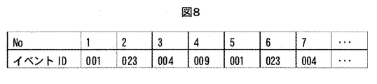
- Figure 8 shows an example of an event sequence.
- the event string is composed of a number indicating the order of the event string and an event ID.
- the event sequence generation unit generates and aggregates events from the acquired data sequence.
- the time when the event is generated represents time information of data immediately after the event generation condition is achieved.
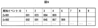
- FIG. 9 shows an example of a known event sequence.
- the known event string has a known event ID and an event string for each known event.
- the known event ID is expressed by a value that can uniquely identify the event. For example, it can be expressed using numbers or by using a plurality of alphabets.
- the event sequence that constitutes the known event sequence is composed of event IDs.
- the known event sequence may be configured using the known event sequence ID in addition to the event ID.
- a vehicle control system according to the second embodiment of the present invention will be described.
- the difference from the first embodiment is that the known event sequence can be simplified by replacing a part of the reported event sequence with the known event sequence.
- Note that the same configurations as those of the above-described embodiment are denoted by the same reference numerals and description thereof is omitted.
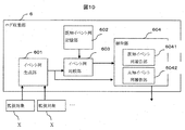
- Fig. 10 shows the configuration of the reporting unit in this example.
- the report unit described in the first embodiment includes a known event sequence report unit 6041 and an unknown event sequence report unit 6042.
- the known event report unit 6041 replaces the matching part of the event sequence obtained from the event sequence generation unit with the known event sequence ID when the comparison result in the event sequence comparison unit 603 matches.
- Fig. 11 shows the event sequence after replacement with the known event sequence.
- the post-replacement event sequence in FIG. 11 was created using the event sequence in FIG. 8 and the known event sequence in FIG.
- the event string comparison unit notifies the determination result indicating matching / mismatching and the known event string ID when matching.
- the known event sequence report unit 6041 searches the event sequence obtained from the event sequence generation unit 601 for a known event sequence that matches the known event sequence ID obtained from the event sequence generation unit. After the search, the found known event sequence is replaced with the event sequence ID, and a post-replacement event sequence is created.
- the known event string reporting unit 6041 notifies the unknown event string reporting unit 6042 of the replaced event string.
- the unknown event string reporting unit 6042 aggregates a predetermined amount of unknown event strings, and outputs them in a batch as a report result of the reporting unit 604.
- the event sequence to be reported is simplified by using the known event sequence ID, so that the burden on the analyst's analysis work is reduced. Further, by using the known event sequence ID, an effect of reducing the data amount of the event sequence can be obtained.
- a vehicle control system according to the third embodiment of the present invention will be described.
- the difference from the second embodiment is that an unknown event sequence that appears multiple times is collected, and an unknown event sequence ID is attached to replace the unknown event sequence ID of the event sequence to be reported with a known event sequence.
- the column can be simplified. Note that the same configurations as those of the above-described embodiment are denoted by the same reference numerals and description thereof is omitted.
- FIG. 12 shows the configuration of the log collection unit 6 in this embodiment.
- an unknown event sequence pattern storage unit 605 is provided, and the unknown event sequence pattern storage unit 605 acquires the replaced event sequence obtained from the unknown event report unit 6042. Then, an unknown event sequence pattern is generated. That is, the unknown event sequence pattern is an unknown event sequence to which an ID is assigned on the condition that it appears multiple times.
- the unknown event sequence pattern comparison unit 606 compares the unknown event sequence pattern ID obtained from the unknown event sequence pattern storage unit 605 with the replaced event sequence.
- the unknown event string pattern comparison unit transmits a comparison result indicating matching / mismatching and an unknown event string pattern ID when matching.
- the unknown event sequence report unit 6042 searches the replaced event sequence for the obtained unknown event sequence pattern ID and replaces it.
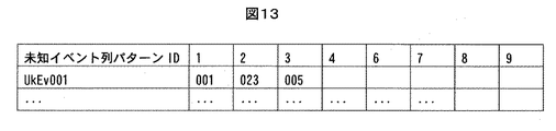
- FIG. 13 shows an unknown event sequence pattern table.
- the unknown event string pattern table has the same information as the known event string ID in FIG.
- the unknown event string pattern ID is expressed by using numerals and alphabets, similarly to the event string ID and the known event string ID. However, it should not overlap with the event string ID and the known event string ID.
- the unknown event sequence pattern may include a known event sequence ID.
- FIG. 14 shows an example in which the post-replacement event sequence of FIG. 11 is replaced with an unknown event sequence pattern ID.
- the reporting unit reports the post-replacement event sequence replaced with the unknown event sequence pattern.
- the event sequence can be further simplified by using the well-known unknown event sequence pattern ID, and the burden on the analyst is reduced.
- the number of known event sequences can be further increased by analyzing the event sequence pattern table in the event sequence pattern storage unit.
- a vehicle control system according to the fourth embodiment of the present invention will be described.
- the difference from the first embodiment is that more detailed data can be acquired by using the reported unknown event sequence as a trigger.
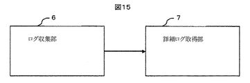
- FIG. 15 shows the log collection unit 6 and the detailed log collection unit 7 indicated by the log collection unit 6.
- the detailed log collection unit is a function provided in the ECU 5 and can be stored using the EEPROM or the application 501.
- the reporting unit 604 receives the comparison result from the event sequence comparison unit, and if it does not match the known event sequence, reports to the detailed log collection unit that an unknown event sequence has been found. In addition to sending an unknown event sequence discovery flag or the like, the report may be sent by sending an event sequence.
- the detailed log collection unit 7 has a function of acquiring a data log of the ECU, receives data normally, and holds data for a certain period or one cycle.
- the detailed log collection unit 7 receives unknown event discovery data from the log collection unit 6, the detailed log collection unit 7 stores data for a certain period from the time of reception in the log storage unit.
- the fixed period refers to several seconds before and several seconds after the unknown event string is reported. It may be specified not only in seconds but also in minutes and hours.
- data can be collected only when an unknown event sequence is discovered, and the analyst can perform more accurate data analysis.
- the log acquisition unit 7 acquires logs based on the unknown event sequence, so that detailed logs can be acquired only in places where analysis is necessary, and the amount of detailed logs collected can be reduced.
- a vehicle control system will be described with reference to FIG.
- the difference from the first embodiment is that the log collection unit can start operation by using an external trigger, so that the calculation can be performed without applying a calculation load during the steady operation.
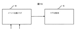
- the event collection trigger 8 is implemented by one function of the ECU 2 or the application 501.
- the event collection trigger 8 acquires data for each cycle, and sends the event collection trigger to the log collection unit 6 when the acquired data is the timing of event collection.
- the log collection unit 6 After acquiring the event collection trigger, the log collection unit 6 performs the operations described in the first to fourth embodiments.
- the log collection prohibition request is output, and the log collection unit 6 cancels the operations described in the first to fourth embodiments after receiving the log acquisition prohibition request.
- the first example shows the state transition of the ECU.
- the state of the ECU represents activation, initialization, normal, abnormality, termination, etc., and represents a necessary state regardless of the application.
- the event collection trigger always acquires a variable that represents the ECU status, and logs the event collection trigger when it is in a transitional period between normal operation such as startup, initialization, error, and termination and the power-off state. Transmit to unit 6.
- the control mode here refers to switching of a calculation method in which functions different from normal driving such as when starting a slope, ACC (Active Cruise Control), sudden braking, etc., other than the normal driving state.
- the control mode is changed based on user button operations or acquired data from sensors such as cameras.
- initial processing specific to each control mode is performed, and the log collection unit collects the log during the initial processing.
- the event collection trigger 8 acquires a flag indicating the control mode of each application 501 every cycle, and transmits the event collection trigger to the log collection unit 6 when the control mode is changed.
- the event collection trigger 8 transmits a log collection stop trigger after a period specified in advance from the control mode change.
- the sudden change in the control command value refers to a case where a driver's operation amount, for example, a brake, an accelerator, a steering wheel, or the like is operated rapidly.
- the event collection trigger 8 always acquires the operation amount of the driver, and sends an event collection trigger to the log collection unit 6 when a sudden change in value is detected.
- the event collection trigger 8 transmits a log collection stop trigger after a predetermined period has passed since the event collection trigger was sent.
Landscapes
- Engineering & Computer Science (AREA)
- Theoretical Computer Science (AREA)
- Quality & Reliability (AREA)
- Physics & Mathematics (AREA)
- General Engineering & Computer Science (AREA)
- General Physics & Mathematics (AREA)
- Computer Hardware Design (AREA)
- Mechanical Engineering (AREA)
- Debugging And Monitoring (AREA)
- Traffic Control Systems (AREA)
- Testing And Monitoring For Control Systems (AREA)
Abstract
本発明は、顕在化していない不具合を解析できるデータ収集を可能とすることを目的とする。本発明は、監視対象から出力される出力結果に基づいて一つまたは複数のイベントからなるイベント列を生成するイベント列生成部と、予め既知のイベント列を記憶する既知イベント列記憶部と、前記イベント列生成部で生成されたイベント列と前記既知のイベント列とを比較するイベント列比較部と、生成されたイベント列の中から前記既知のイベント列と一致しない未知のイベント列を抽出して報告する報告部と、を備える。
Description
本発明は、自動車の車両制御装置に関する。
本技術分野の背景技術として、特開2010-267207号公報(特許文献1)がある。この公報には、「観測データの特異性を判定することができても、観測データがどの程度基準パターンから外れているか、すなわち、どの程度非日常的なデータであるかを知ること」を課題とし、解決手段として、「ユーザの行動によって得られるイベントデータ系列について、ユーザの日常的な行動を表す基準パターンに対してどの程度日常的でないかを評価することのできる非日常性評価装置、非日常性評価方法及びコンピュータプログラムを提供する」と記載されている。
車両制御装置においても、得られたデータ系列と車両の正常な動作を示すパターンとの乖離を評価することで、どれだけ異常な動作をしているかを評価することができる。もし、車両制御装置では異常なパターンを発見した場合は、異常時のデータ系列が不具合に繋がるかを分析し、もし不具合に繋がるのであれば、制御を修正し製品に反映させなければならない。しかしながら、特許文献1では、非日常時のデータ系列を出力することができない。
本発明は、顕在化していない不具合を解析できるデータ収集を可能とすることを目的とする。
本発明は、監視対象から出力される出力結果に基づいて一つまたは複数のイベントからなるイベント列を生成するイベント列生成部と、予め既知のイベント列を記憶する既知イベント列記憶部と、前記イベント列生成部で生成されたイベント列と前記既知のイベント列とを比較するイベント列比較部と、生成されたイベント列の中から前記既知のイベント列と一致しない未知のイベント列を抽出して報告する報告部と、を備える。
本発明によれば、顕在化していない不具合を解析できるデータ収集が可能な車両制御装置を提供することができる。
以下、本発明に好適な実施形態の例(実施例)を説明する。本実施例は、主には車両システムにおける車両制御システムについて説明しており、車両システムにおける実施に好適であるが、車両システム以外への適用を妨げるものではない。
<車両の概要>
図1に、本実施例の車両制御システムが有する車両制御装置を用いたシステム構成を示す。車両制御システム1は、複数のECU(Electronic Control Unit等)2が接続された車載ネットワーク3(CAN:Controller Area Network、CANFD:CAN with Flexible Data-rate、Ethernet(登録商標)、等)とで構成される。車載ネットワーク3は、車両制御システム外のネットワークと社外通信経路4(例えば携帯電話の通信、無線LAN、WAN、等のプロトコルを使用した通信)で接続されており、ECU2で計算された情報を車外へ送信したり、車外のデータを受信し、車内ネットワーク3へと通知することができる。
図1に、本実施例の車両制御システムが有する車両制御装置を用いたシステム構成を示す。車両制御システム1は、複数のECU(Electronic Control Unit等)2が接続された車載ネットワーク3(CAN:Controller Area Network、CANFD:CAN with Flexible Data-rate、Ethernet(登録商標)、等)とで構成される。車載ネットワーク3は、車両制御システム外のネットワークと社外通信経路4(例えば携帯電話の通信、無線LAN、WAN、等のプロトコルを使用した通信)で接続されており、ECU2で計算された情報を車外へ送信したり、車外のデータを受信し、車内ネットワーク3へと通知することができる。
<車両ECUの概要>
図2にECU2の構成を示す。ECU2には、車載ネットワーク3へと接続する通信装置201と、プログラムおよび不揮発性のデータを保存するROM(Read Only Memory)202と、揮発性のデータを保存するRAM(Random Access Memory)203と、キャッシュやレジスタなどの記憶素子を持ち、制御を実行するCPUなどのプロセッサ204と、専用線で接続された駆動装置または/および認識装置6に対してデータの送受信やセンサなどから観測値を取得する入出力装置205で構成される。
図2にECU2の構成を示す。ECU2には、車載ネットワーク3へと接続する通信装置201と、プログラムおよび不揮発性のデータを保存するROM(Read Only Memory)202と、揮発性のデータを保存するRAM(Random Access Memory)203と、キャッシュやレジスタなどの記憶素子を持ち、制御を実行するCPUなどのプロセッサ204と、専用線で接続された駆動装置または/および認識装置6に対してデータの送受信やセンサなどから観測値を取得する入出力装置205で構成される。
<ソフトウェアの概要>
次にプロセッサ203で動作するソフトウェアモジュール5の構成について図3に示す。アプリケーション501はソフトウェアに1以上存在するソフトウェアモジュールである。アプリケーション501は、駆動装置の制御量や、センサから得られた情報の加工や、センサから得られた情報から推測するドライバの操作量の計算や、故障診断などの、車両制御部品のソフトウェアが計算する機能を計算する。アプリケーション間は相互にデータ送受信しており、RTE502や車載ネットワーク3を介したデータの交換や、アプリケーション同士のデータの交換を行う。
次にプロセッサ203で動作するソフトウェアモジュール5の構成について図3に示す。アプリケーション501はソフトウェアに1以上存在するソフトウェアモジュールである。アプリケーション501は、駆動装置の制御量や、センサから得られた情報の加工や、センサから得られた情報から推測するドライバの操作量の計算や、故障診断などの、車両制御部品のソフトウェアが計算する機能を計算する。アプリケーション間は相互にデータ送受信しており、RTE502や車載ネットワーク3を介したデータの交換や、アプリケーション同士のデータの交換を行う。
RTE(Run Time Environment)502は、アプリケーション501に対してデータ送受信のためのインタフェースを提供する。アプリケーション501は、RTEを用いてデータ送受信を行うことで、ECU2の構成に依存するBSW504に依存することなくデータの送受信が可能となる。RTE502はソフトウェアに存在しなくともよく、その場合は各アプリケーションはデータの送受信先モジュールに応じたデータ送受信をプログラミングする必要がある。
BSW503は、ECU2のハードウェア構成に依存する機能を実装するソフトウェア部である。例えば、オペレーティングシステムや通信ソフトウェア、各種入出力装置から得られる電流値がBSWに相当する。
ログ収集部6はアプリケーション501の一種である。図4にログ収集部6の構造を示す。イベント列生成部601は後述するルールにより、後述するデータ列を後述するイベント列に変換する。イベント列とは、いわば、複数のイベントの集まりである。イベント列生成部601は、後述する監視対象Xからデータを入手しデータ列を構成する。既知イベント列記憶部602は、事前に収集した正常な既知イベント列を予め記憶している。イベント列比較部603は既知イベント列に保存された既知イベント列と、イベント列生成部601で構成されたイベント列と比較し、得られたイベント列が既知であるかを判定し判定結果を出力する。報告部604は、イベント列比較部から得られた判定結果と、判定に用いたイベント列を、ログ収集部の出力として出力する。具体的には、報告部604は、生成されたイベント列の中から既知イベント列と一致しない未知イベント列を抽出して報告する。未知イベント列とは、既知イベント列記憶部602に予め登録されていないイベント列である。
監視対象は、同じECU内のアプリケーション501やBSW503や、異なるECUや、モータなどの駆動装置や、入出力装置205に繋がるセンサなど、後述するデータ列を構成可能なデータを計算するものがあてはまる 図7にイベント列生成部601の構造を示す。イベント列生成部601は、データ取得部6011と、イベント生成部6012と、イベント列構成部6013、とで構成されている。データ取得部6011は、監視対象Xから得られたデータを取得し、後述するデータ列を構成する。イベント生成部6012は、後述するイベントを後述するイベント生成条件に照らし合わせて生成する。イベント列構成部6013は、イベント生成部6012で構成されたイベントを、後述するイベント列形式に形成する。
<データ列>
図6にデータ列の例を示す。データ列を構成するデータは、アプリケーションの計算結果や、センサのデータや、BSWやOSの状態や、プロセッサの命令や、時間情報といった制御装置が計算し取得する値を示す。データ列は得られたデータを時系列や、受信した順序で並べたデータの列を表す。
図6にデータ列の例を示す。データ列を構成するデータは、アプリケーションの計算結果や、センサのデータや、BSWやOSの状態や、プロセッサの命令や、時間情報といった制御装置が計算し取得する値を示す。データ列は得られたデータを時系列や、受信した順序で並べたデータの列を表す。
<イベント列>
図7に、イベント列の例を示す。イベント列を構成するイベントは、データ列を構成するデータが変化した場合の情報を表す。ここでのデータが変化した場合とは、例えばセンサが取得した、車体の速度が一定の値から減少に転じた場合、「速度が減少に転じたこと」がイベントとなる。この場合には、「速度が減少に転じたこと」を表すイベントIDが得られる。また、別の例として、ECUの電源が入り、初期化が開始された場合は「初期化開始」を表わすイベントIDが得られる。また、別の例として、ドライバーがブレーキペダルを踏んだ際に、ブレーキペダルの踏み込み量が一定以上になったことを検知し「ブレーキ踏み有り」のイベントIDが得られる。
図7に、イベント列の例を示す。イベント列を構成するイベントは、データ列を構成するデータが変化した場合の情報を表す。ここでのデータが変化した場合とは、例えばセンサが取得した、車体の速度が一定の値から減少に転じた場合、「速度が減少に転じたこと」がイベントとなる。この場合には、「速度が減少に転じたこと」を表すイベントIDが得られる。また、別の例として、ECUの電源が入り、初期化が開始された場合は「初期化開始」を表わすイベントIDが得られる。また、別の例として、ドライバーがブレーキペダルを踏んだ際に、ブレーキペダルの踏み込み量が一定以上になったことを検知し「ブレーキ踏み有り」のイベントIDが得られる。
イベントは連続する物理値の変化以外にも、フラグの切り替わりをイベントとして取得しできる。例えば、モータの連続動作時間が一定時間異常になった場合、高温になり過ぎないようにモータの動作を制限する制御がある、「連続動作時間一定以上」などを表すイベントIDが得られる。また別の例として、ドライバーがACC(Accel Cruise Control)のスイッチをONにした情報を取得し、「ACCフラグON」を示すイベントIDが得られる。
イベントはその他にも、タスクの切り替わりや関数の終了などの処理の切り替わりをイベントとして取得できる。このように、イベントとは、例えば、単一の制御値の変化内容を指すものである。
イベントIDは、イベントを一意に識別できる値で表現される。例えば、数字を用いて番号を振る、又は複数のアルファベットを用いて表現できる。
イベント列生成部は、データ列から、各イベントIDに関連したデータを抜粋し、イベントを判定する。データ列は、イベントごとに個別にデータを集めてもよいし、複数のイベントに関連する複数のデータを同時に収集してよい。図3にデータ列の例を示す。図3
(a)が示すデータ列は、速度を時系列順に取得している。
(a)が示すデータ列は、速度を時系列順に取得している。
データは速度以外の物理値や、カウンタなどの連続した数値を使用しても良い。また、同じ物理値を表現した、異なる変数を収集する場合、変数毎に収集しデータ列を構成しても良い。
時間は、秒や分や時間といった単位によって表現できる。整数だけでなく、少数で時間を表現してよい。また、秒や分や時間などの時間情報は、データを取得した日時を表す絶対時間や、基準となるデータの取得時間からの相対時間での表現も可能である。例えば、10ms毎など周期的に取得可能なデータは、時間情報ではなく、取得した順番(1、2、3、4・・・)で表現しても良い。
図7に、データ列をイベントに変換するための変換情報の例を示す。各イベントは、イベントIDと、監視するデータ情報を変換情報として持つ。監視するデータ情報は、図4に示すデータを指定する。イベント生成条件については、後述する。
図8に、イベント列の例を示す。イベント列は、イベント列の順序を表すNoとイベントIDで構成される。イベント列生成部は、取得したデータ列からイベントを生成し、集約する。
集約したイベントを時系列順に並べ替えイベント列を構成する。ここで、イベントを生成した時間とは、イベント生成条件を達成した直後のデータの時間情報を表す。
<既知イベント列>
図9に、既知イベント列の例を示す。既知イベント列は、各既知イベントごとに、既知イベントIDとイベント列を持つ。既知イベントIDはイベントを一意に識別できる値で表現される。例えば、数字を用いて番号を振る、又は複数のアルファベットを用いて表現できる。
図9に、既知イベント列の例を示す。既知イベント列は、各既知イベントごとに、既知イベントIDとイベント列を持つ。既知イベントIDはイベントを一意に識別できる値で表現される。例えば、数字を用いて番号を振る、又は複数のアルファベットを用いて表現できる。
既知イベント列を構成するイベント列は、イベントIDで構成される。また、イベントIDと既知イベント列IDが重複しない場合、イベントID以外に既知イベント列IDを用いて、既知イベント列を構成しても良い。
本発明にかかる第2の実施例における車両制御システムについて説明する。第1の実施例と異なる点は、報告するイベント列の一部を既知イベント列と置き換えることで、既知イベント列を簡略化可能な点である。なお、先に説明した実施例と同様の構成は符号を同じくして説明を省略する。
図10に本実施例における、報告部の構成を示す。実施例1に記載の報告部に、既知イベント列報告部6041と、未知イベント列報告部6042を備える。
既知イベント報告部6041は、イベント列比較部603での比較結果が、一致していた場合、イベント列生成部より得られたイベント列の一致部分を既知イベント列IDで置換する。
図11に、既知イベント列で置換後のイベント列を示す。図11の置換後イベント列は、図8のイベント列と図9の既知イベント列を用いて作成した。
本実施例において、イベント列比較部は、一致・不一致を示す判定結果と、一致した場合の既知イベント列IDを通知する。既知イベント列報告部6041は、イベント列生成部601から得られたイベント列から、イベント列生成部から得られた既知イベント列IDに一致する既知イベント列を探索する。探索後、見つかった既知イベント列をイベント列IDへと置換し、置換後イベント列を作成する。既知イベント列報告部6041は、未知イベント列報告部6042へ置換後イベント列を通知する。未知イベント列報告部6042は、あらかじめ決められた分量の未知イベント列を集約し、一括して、報告部604の報告結果として出力する。
本実施例を用いることで、報告するイベント列は既知イベント列IDを用いて簡略化されるため、解析者の解析作業の負担が軽減する。また、既知イベント列IDを用いたことで、イベント列のデータ量を削減する効果も得られる。
本発明にかかる第3の実施例における車両制御システムについて説明する。第2の実施例と異なる点は、複数回出現する未知イベント列を収集し、未知イベント列IDをつけることで、報告するイベント列の未知イベント列IDを既知イベント列と置き換えることで、既知イベント列を簡略化可能な点である。なお、先に説明した実施例と同様の構成は符号を同じくして説明を省略する。
図12に本実施例における、ログ収集部6の構成を示す。本実施例では、未知イベント列パターン記憶部605を備え、未知イベント列パターン記憶部605は、未知イベント報告部6042より得られた置換済みイベント列を取得する。そして、未知イベント列パターンを生成する。即ち、未知イベント列パターンとは、複数回登場することを条件としてIDが付与された未知イベント列である。未知イベント列パターン比較部606は、未知イベント列パターン記憶部605から得られた未知イベント列パターンIDと、置換後イベント列とを比較する。未知イベント列パターン比較部は、一致・不一致を示す比較結果と、一致した場合は未知イベント列パターンIDを送信する。
未知イベント列報告部6042は、得られた未知イベント列パターンIDを、置換後イベント列から探索し、置換する。
図13に、未知イベント列パターンテーブルを示す。未知イベント列パターンテーブルは、図9の既知イベント列IDと同じ情報を持つ。ここで未知イベント列パターンIDは、イベント列ID,既知イベント列IDと同様に、数字やアルファベットを用いて表現する。ただし、イベント列ID及び既知イベント列IDと重複してはいけない。また、未知イベント列パターンには既知イベント列IDを含めても良い。図14に、図11の置換後イベント列に対して、未知イベント列パターンIDで置換した例を示す。
報告部は、未知イベント列パターンで置換した置換後イベント列を報告する。
本実施例により、イベント列は良く出る未知イベント列パターンIDを用いて更に簡素化でき、解析担当者の負担が減少する。また、イベント列パターン記憶部のイベント列パターンテーブルを解析することで、既知イベント列を更に増やすことができる。
本発明にかかる第4の実施例における車両制御システムについて説明する。第1の実施例と異なる点は、報告した未知イベント列をトリガとして、より詳細なデータを取得可能な点である。
図15に、ログ収集部6と、ログ収集部6が示す詳細ログ収集部7を示す。詳細ログ収集部は、ECU5に備えられた機能であり、EEPROMやアプリケーション501を用いて保存できる。
本実施例において、報告部604は、イベント列比較部から比較結果を受け取り、既知イベント列と不一致であった場合、未知イベント列を発見したとして、詳細ログ収集部へと報告する。報告には、未知イベント列発見フラグなどの送付のほか、イベント列を送付することで報告としても良い。
詳細ログ収集部7は、ECUのデータログを取得する機能を有しており、普段からデータを受信し、一定期間もしくは1周期分のデータを保持している。詳細ログ収集部7は、ログ収集部6から、未知イベント発見のデータを受信した際に、受信時からの一定期間のデータを、ログ保存部に保存する。
一定期間とは、未知イベント列報告時から、数秒前から数秒後を指す。秒単位だけではなく、分・時間で指定しても良い。
本実施例を用いることで、未知イベント列が発見されたときのみデータを収集することができ、解析者はより正確なデータ解析が可能になる。また、ログ取得部7は、未知イベント列を元にログ取得することにより、解析が必要そうな箇所に絞って詳細なログが取得可能になり、詳細ログの収集量を削減できる。
本発明にかかる第5の実施例における車両制御システムについて図16を用いて説明する。第1の実施例と異なる点は、外部のトリガを用いて、ログ収集部が動作を始めることで、定常動作時に計算負荷をかけずに行うことができる点である。
イベント収集トリガ8は、ECU2の一機能、又はアプリケーション501によって実装される。イベント収集トリガ8は、毎周期データを取得しており、取得したデータがイベント収集するタイミングであった場合に、ログ収集部6にイベント収集トリガを送付する。ログ収集部6は、イベント収集トリガを取得した後、実施例1から4に記載の動作を行う。また、イベント収集トリガ8はイベント収集タイミングではないとき、ログ取得禁止の要求を出力し、ログ収集部6はログ取得禁止の要求受信後、実施例1から4に記載の動作を取りやめる。
イベント収集トリガ8は、ECU2の一機能、又はアプリケーション501によって実装される。イベント収集トリガ8は、毎周期データを取得しており、取得したデータがイベント収集するタイミングであった場合に、ログ収集部6にイベント収集トリガを送付する。ログ収集部6は、イベント収集トリガを取得した後、実施例1から4に記載の動作を行う。また、イベント収集トリガ8はイベント収集タイミングではないとき、ログ取得禁止の要求を出力し、ログ収集部6はログ取得禁止の要求受信後、実施例1から4に記載の動作を取りやめる。
本実施例におけるイベントを収集するタイミングの例を示す。第一の例は、ECUの状態遷移時を示す。ECUの状態とは、起動、初期化、通常、異常、終了、などを表し、アプリケーションによらず必要な状態を表す。イベント収集トリガは、ECUの状態を表す変数を常に取得しており、起動、初期化、異常、終了などの通常動作と電源停止状態との過渡期にある状態のとき、イベント収集トリガをログ収集部6に送信する。
第二の例として、アプリケーションの制御モード変更時の例を示す。ここでの制御モードとは、通常の走行状態以外に、坂道発進時、ACC(Active Cruise Control)、急ブレーキ時、など通常の走行時とは異なる機能が動作する計算方式の切替をさす。制御モード変更は、ユーザのボタン操作又は、カメラなどのセンサの取得データを基に行われる。制御モード変更直後は各制御モード特有の初期処理などが行われるため、ログ収集部にてその初期処理時のログ収集を行う。イベント収集トリガ8は、各アプリケーション501の制御モードを示すフラグを毎周期取得しており、制御モードの変更があった際にログ収集部6にイベント収集トリガを送信する。イベント収集トリガ8は、制御モード変更からあらかじめ指定された期間を過ぎた後に、ログ収集停止トリガを送信する。
第3の例として、制御指令値急変時の例を示す。制御指令値の急変とは、運転手の操作量、例えばブレーキやアクセルやハンドルなどの操作を急激に行った場合を指す。イベント収集トリガ8は、常にドライバーの操作量を取得しておき、値の急変を察知した場合にログ収集部6へとイベント収集トリガを送付する。イベント収集トリガ8は、イベント収集トリガ送付からあらかじめ指定された期間を過ぎた後に、ログ収集停止トリガを送信する。
本実施例により、定常とは異なる制御が行われた際の、ログを集中して収集することで、不具合などの異常を発見しやすいログに絞った収集が可能になる。
1 車両制御システム2 ECU3 車載ネットワーク4 車両制御システム5 ソフトウェアモジュール6 ログ収集部7 出力装置8 入力装置201 通信装置202 ROM(Read Only Memory)203 RAM(Random Access Memory)204 CPU205 入出力装置501 アプリケーション502 RTE503 BSW601 イベント列生成部602 既知イベント列記憶部603 イベント列比較部604 報告部6011 データ取得部6012 イベント生成部6013 イベント列構成部6041 既知イベント列報告部6042 未知イベント列報告部605 未知イベント列パターン記憶部606 未知イベント列比較部X 監視対象
Claims (5)
- 監視対象から出力される出力結果に基づいて一つまたは複数のイベントからなるイベント列を生成するイベント列生成部と、
予め既知のイベント列を記憶する既知イベント列記憶部と、
前記イベント列生成部で生成されたイベント列と前記既知のイベント列とを比較するイベント列比較部と、
生成されたイベント列の中から前記既知のイベント列と一致しない未知のイベント列を抽出して報告する報告部と、
を備える車両制御装置。 - 前記既知イベント列記憶部は、既知のイベント列と、該既知のイベント列を識別する識別情報とを記憶し、
前記報告部は、生成されたイベント列が既知のイベント列と一致した場合は、前記既知のイベント列に関する識別情報を報告する、請求項1に記載の車両制御装置。 - 前記未知のイベント列が抽出された場合、前記監視対象からの出力結果のうち該未知のイベント列に関する出力結果を報告する、請求項1に記載の車両制御装置。
- 前記未知イベント列の報告結果を保持し識別情報を付与する未知イベント列パターン記憶部を持つことを特徴とする、請求項1に記載の車両制御装置。
- 未知のイベント列が抽出された場合、前記未知のイベント列が前記未知イベント列パターン記憶部に登録されているかを判定し、登録されている場合は未知イベント列を前記未知イベント列パターン記憶部に記載されている識別情報へと置き換える同一未知イベント列判定部を備える、請求項1に記載の車両制御装置。
Applications Claiming Priority (2)
| Application Number | Priority Date | Filing Date | Title |
|---|---|---|---|
| JP2016027520A JP6655416B2 (ja) | 2016-02-17 | 2016-02-17 | 車両制御装置 |
| JP2016-027520 | 2016-12-20 |
Publications (1)
| Publication Number | Publication Date |
|---|---|
| WO2017141589A1 true WO2017141589A1 (ja) | 2017-08-24 |
Family
ID=59624996
Family Applications (1)
| Application Number | Title | Priority Date | Filing Date |
|---|---|---|---|
| PCT/JP2017/000910 Ceased WO2017141589A1 (ja) | 2016-02-17 | 2017-01-13 | 車両制御装置 |
Country Status (2)
| Country | Link |
|---|---|
| JP (1) | JP6655416B2 (ja) |
| WO (1) | WO2017141589A1 (ja) |
Cited By (2)
| Publication number | Priority date | Publication date | Assignee | Title |
|---|---|---|---|---|
| WO2020065960A1 (ja) * | 2018-09-28 | 2020-04-02 | 日本電気株式会社 | 情報処理装置、制御方法、及びプログラム |
| CN111210634A (zh) * | 2020-02-27 | 2020-05-29 | 周国霞 | 智能交通信息处理方法、装置、智能交通系统及服务器 |
Families Citing this family (3)
| Publication number | Priority date | Publication date | Assignee | Title |
|---|---|---|---|---|
| CN112789600B (zh) | 2018-11-30 | 2024-12-06 | 松下电器(美国)知识产权公司 | 车辆日志发送装置、车辆日志分析服务器、车辆日志分析系统以及车辆日志收发方法 |
| JP7766424B2 (ja) * | 2021-07-28 | 2025-11-10 | Astemo株式会社 | 車載処理装置 |
| US20250239114A1 (en) * | 2024-01-24 | 2025-07-24 | Toyota Jidosha Kabushiki Kaisha | Systems and methods for managing vehicle event data |
Citations (5)
| Publication number | Priority date | Publication date | Assignee | Title |
|---|---|---|---|---|
| JP2007087186A (ja) * | 2005-09-22 | 2007-04-05 | Fuji Xerox Co Ltd | ログ収集システムおよび方法 |
| JP2007536646A (ja) * | 2004-05-04 | 2007-12-13 | アークサイト,インク. | ネットワーク・セキュリティ・システムにおけるパターン発見方法及びシステム |
| JP2009003685A (ja) * | 2007-06-21 | 2009-01-08 | Honda Motor Co Ltd | データ記憶装置、データ記憶方法、及びデータ記憶用プログラム |
| JP2012094046A (ja) * | 2010-10-28 | 2012-05-17 | Hitachi Medical Corp | 機器障害分析装置、機器障害分析方法、および機器障害分析プログラム |
| JP2016024786A (ja) * | 2014-07-24 | 2016-02-08 | 富士通フロンテック株式会社 | ログ解析装置 |
-
2016
- 2016-02-17 JP JP2016027520A patent/JP6655416B2/ja active Active
-
2017
- 2017-01-13 WO PCT/JP2017/000910 patent/WO2017141589A1/ja not_active Ceased
Patent Citations (5)
| Publication number | Priority date | Publication date | Assignee | Title |
|---|---|---|---|---|
| JP2007536646A (ja) * | 2004-05-04 | 2007-12-13 | アークサイト,インク. | ネットワーク・セキュリティ・システムにおけるパターン発見方法及びシステム |
| JP2007087186A (ja) * | 2005-09-22 | 2007-04-05 | Fuji Xerox Co Ltd | ログ収集システムおよび方法 |
| JP2009003685A (ja) * | 2007-06-21 | 2009-01-08 | Honda Motor Co Ltd | データ記憶装置、データ記憶方法、及びデータ記憶用プログラム |
| JP2012094046A (ja) * | 2010-10-28 | 2012-05-17 | Hitachi Medical Corp | 機器障害分析装置、機器障害分析方法、および機器障害分析プログラム |
| JP2016024786A (ja) * | 2014-07-24 | 2016-02-08 | 富士通フロンテック株式会社 | ログ解析装置 |
Cited By (5)
| Publication number | Priority date | Publication date | Assignee | Title |
|---|---|---|---|---|
| WO2020065960A1 (ja) * | 2018-09-28 | 2020-04-02 | 日本電気株式会社 | 情報処理装置、制御方法、及びプログラム |
| JPWO2020065960A1 (ja) * | 2018-09-28 | 2021-08-30 | 日本電気株式会社 | 情報処理装置、制御方法、及びプログラム |
| JP7180681B2 (ja) | 2018-09-28 | 2022-11-30 | 日本電気株式会社 | 情報処理装置、制御方法、及びプログラム |
| US11762713B2 (en) | 2018-09-28 | 2023-09-19 | Nec Corporation | Information processing apparatus, control method, and program |
| CN111210634A (zh) * | 2020-02-27 | 2020-05-29 | 周国霞 | 智能交通信息处理方法、装置、智能交通系统及服务器 |
Also Published As
| Publication number | Publication date |
|---|---|
| JP2017144852A (ja) | 2017-08-24 |
| JP6655416B2 (ja) | 2020-02-26 |
Similar Documents
| Publication | Publication Date | Title |
|---|---|---|
| US11541899B2 (en) | Vehicle diagnosis apparatus, vehicle diagnosis system, and vehicle diagnosis program | |
| JP6655416B2 (ja) | 車両制御装置 | |
| JP4453764B2 (ja) | 車両診断装置、車両診断システム、診断方法 | |
| KR102340477B1 (ko) | 기계 모니터링 | |
| KR102444442B1 (ko) | 설비 고장 진단 장치 및 방법 | |
| US20140081508A1 (en) | Automotive Control Unit and Automotive Control System | |
| JP7588587B2 (ja) | 攻撃検知方法、攻撃検知システム、及びプログラム | |
| JP2008186472A5 (ja) | ||
| WO2012128256A1 (ja) | 車両データ解析装置、車両データ解析方法、及び故障診断装置 | |
| JP2009294004A (ja) | 異常解析装置及び異常解析方法 | |
| CN105209995A (zh) | 监视系统及其诊断装置和监视终端 | |
| WO2020110446A1 (ja) | 車両故障予測システム、監視装置、車両故障予測方法および車両故障予測プログラム | |
| CN102749425B (zh) | 一种发动机机体疲劳试验裂纹诊断方法和装置 | |
| US12190658B2 (en) | Fault diagnosis device, fault diagnosis system, fault diagnosis method, and fault diagnosis program | |
| WO2020202850A1 (ja) | 情報処理装置 | |
| JP4417318B2 (ja) | 設備診断装置 | |
| JP7491240B2 (ja) | 情報処理装置、情報処理方法、およびプログラム | |
| CN112995061B (zh) | 车辆数据传输方法、装置、系统及存储介质 | |
| JP4315073B2 (ja) | 故障解析システム | |
| US12051288B2 (en) | Fault sign detection device, fault sign detection system, fault sign method, and fault sign detection program | |
| JP7643305B2 (ja) | 運転者特定装置、運転者特定方法、及び運転者特定プログラム | |
| JP2020098615A (ja) | 車両制御装置 | |
| JP7367773B2 (ja) | 故障診断装置、故障診断システム、故障診断方法および故障診断プログラム | |
| CN113568815A (zh) | 基于大数据的工业制造设备故障诊断方法、装置及电子设备 | |
| CN114518741A (zh) | 自动驾驶车辆的监控方法、监控装置以及监控系统 |
Legal Events
| Date | Code | Title | Description |
|---|---|---|---|
| 121 | Ep: the epo has been informed by wipo that ep was designated in this application |
Ref document number: 17752853 Country of ref document: EP Kind code of ref document: A1 |
|
| NENP | Non-entry into the national phase |
Ref country code: DE |
|
| 122 | Ep: pct application non-entry in european phase |
Ref document number: 17752853 Country of ref document: EP Kind code of ref document: A1 |