WO2017138538A1 - 照明器具 - Google Patents
照明器具 Download PDFInfo
- Publication number
- WO2017138538A1 WO2017138538A1 PCT/JP2017/004455 JP2017004455W WO2017138538A1 WO 2017138538 A1 WO2017138538 A1 WO 2017138538A1 JP 2017004455 W JP2017004455 W JP 2017004455W WO 2017138538 A1 WO2017138538 A1 WO 2017138538A1
- Authority
- WO
- WIPO (PCT)
- Prior art keywords
- bottom plate
- emitting device
- led light
- lighting fixture
- light emitting
- Prior art date
- Legal status (The legal status is an assumption and is not a legal conclusion. Google has not performed a legal analysis and makes no representation as to the accuracy of the status listed.)
- Ceased
Links
Images



Classifications
-
- F—MECHANICAL ENGINEERING; LIGHTING; HEATING; WEAPONS; BLASTING
- F21—LIGHTING
- F21V—FUNCTIONAL FEATURES OR DETAILS OF LIGHTING DEVICES OR SYSTEMS THEREOF; STRUCTURAL COMBINATIONS OF LIGHTING DEVICES WITH OTHER ARTICLES, NOT OTHERWISE PROVIDED FOR
- F21V29/00—Protecting lighting devices from thermal damage; Cooling or heating arrangements specially adapted for lighting devices or systems
- F21V29/50—Cooling arrangements
- F21V29/502—Cooling arrangements characterised by the adaptation for cooling of specific components
- F21V29/503—Cooling arrangements characterised by the adaptation for cooling of specific components of light sources
-
- F—MECHANICAL ENGINEERING; LIGHTING; HEATING; WEAPONS; BLASTING
- F21—LIGHTING
- F21V—FUNCTIONAL FEATURES OR DETAILS OF LIGHTING DEVICES OR SYSTEMS THEREOF; STRUCTURAL COMBINATIONS OF LIGHTING DEVICES WITH OTHER ARTICLES, NOT OTHERWISE PROVIDED FOR
- F21V29/00—Protecting lighting devices from thermal damage; Cooling or heating arrangements specially adapted for lighting devices or systems
- F21V29/50—Cooling arrangements
- F21V29/70—Cooling arrangements characterised by passive heat-dissipating elements, e.g. heat-sinks
- F21V29/74—Cooling arrangements characterised by passive heat-dissipating elements, e.g. heat-sinks with fins or blades
- F21V29/76—Cooling arrangements characterised by passive heat-dissipating elements, e.g. heat-sinks with fins or blades with essentially identical parallel planar fins or blades, e.g. with comb-like cross-section
- F21V29/763—Cooling arrangements characterised by passive heat-dissipating elements, e.g. heat-sinks with fins or blades with essentially identical parallel planar fins or blades, e.g. with comb-like cross-section the planes containing the fins or blades having the direction of the light emitting axis
-
- F—MECHANICAL ENGINEERING; LIGHTING; HEATING; WEAPONS; BLASTING
- F21—LIGHTING
- F21V—FUNCTIONAL FEATURES OR DETAILS OF LIGHTING DEVICES OR SYSTEMS THEREOF; STRUCTURAL COMBINATIONS OF LIGHTING DEVICES WITH OTHER ARTICLES, NOT OTHERWISE PROVIDED FOR
- F21V29/00—Protecting lighting devices from thermal damage; Cooling or heating arrangements specially adapted for lighting devices or systems
- F21V29/50—Cooling arrangements
- F21V29/70—Cooling arrangements characterised by passive heat-dissipating elements, e.g. heat-sinks
- F21V29/80—Cooling arrangements characterised by passive heat-dissipating elements, e.g. heat-sinks with pins or wires
-
- F—MECHANICAL ENGINEERING; LIGHTING; HEATING; WEAPONS; BLASTING
- F21—LIGHTING
- F21V—FUNCTIONAL FEATURES OR DETAILS OF LIGHTING DEVICES OR SYSTEMS THEREOF; STRUCTURAL COMBINATIONS OF LIGHTING DEVICES WITH OTHER ARTICLES, NOT OTHERWISE PROVIDED FOR
- F21V7/00—Reflectors for light sources
- F21V7/04—Optical design
- F21V7/06—Optical design with parabolic curvature
-
- F—MECHANICAL ENGINEERING; LIGHTING; HEATING; WEAPONS; BLASTING
- F21—LIGHTING
- F21V—FUNCTIONAL FEATURES OR DETAILS OF LIGHTING DEVICES OR SYSTEMS THEREOF; STRUCTURAL COMBINATIONS OF LIGHTING DEVICES WITH OTHER ARTICLES, NOT OTHERWISE PROVIDED FOR
- F21V29/00—Protecting lighting devices from thermal damage; Cooling or heating arrangements specially adapted for lighting devices or systems
- F21V29/85—Protecting lighting devices from thermal damage; Cooling or heating arrangements specially adapted for lighting devices or systems characterised by the material
- F21V29/86—Ceramics or glass
-
- F—MECHANICAL ENGINEERING; LIGHTING; HEATING; WEAPONS; BLASTING
- F21—LIGHTING
- F21V—FUNCTIONAL FEATURES OR DETAILS OF LIGHTING DEVICES OR SYSTEMS THEREOF; STRUCTURAL COMBINATIONS OF LIGHTING DEVICES WITH OTHER ARTICLES, NOT OTHERWISE PROVIDED FOR
- F21V29/00—Protecting lighting devices from thermal damage; Cooling or heating arrangements specially adapted for lighting devices or systems
- F21V29/85—Protecting lighting devices from thermal damage; Cooling or heating arrangements specially adapted for lighting devices or systems characterised by the material
- F21V29/89—Metals
-
- F—MECHANICAL ENGINEERING; LIGHTING; HEATING; WEAPONS; BLASTING
- F21—LIGHTING
- F21Y—INDEXING SCHEME ASSOCIATED WITH SUBCLASSES F21K, F21L, F21S and F21V, RELATING TO THE FORM OR THE KIND OF THE LIGHT SOURCES OR OF THE COLOUR OF THE LIGHT EMITTED
- F21Y2115/00—Light-generating elements of semiconductor light sources
- F21Y2115/10—Light-emitting diodes [LED]
-
- H—ELECTRICITY
- H10—SEMICONDUCTOR DEVICES; ELECTRIC SOLID-STATE DEVICES NOT OTHERWISE PROVIDED FOR
- H10H—INORGANIC LIGHT-EMITTING SEMICONDUCTOR DEVICES HAVING POTENTIAL BARRIERS
- H10H20/00—Individual inorganic light-emitting semiconductor devices having potential barriers, e.g. light-emitting diodes [LED]
- H10H20/80—Constructional details
- H10H20/81—Bodies
- H10H20/822—Materials of the light-emitting regions
- H10H20/824—Materials of the light-emitting regions comprising only Group III-V materials, e.g. GaP
- H10H20/825—Materials of the light-emitting regions comprising only Group III-V materials, e.g. GaP containing nitrogen, e.g. GaN
-
- H—ELECTRICITY
- H10—SEMICONDUCTOR DEVICES; ELECTRIC SOLID-STATE DEVICES NOT OTHERWISE PROVIDED FOR
- H10H—INORGANIC LIGHT-EMITTING SEMICONDUCTOR DEVICES HAVING POTENTIAL BARRIERS
- H10H20/00—Individual inorganic light-emitting semiconductor devices having potential barriers, e.g. light-emitting diodes [LED]
- H10H20/80—Constructional details
- H10H20/85—Packages
- H10H20/858—Means for heat extraction or cooling
- H10H20/8581—Means for heat extraction or cooling characterised by their material
-
- H—ELECTRICITY
- H10—SEMICONDUCTOR DEVICES; ELECTRIC SOLID-STATE DEVICES NOT OTHERWISE PROVIDED FOR
- H10H—INORGANIC LIGHT-EMITTING SEMICONDUCTOR DEVICES HAVING POTENTIAL BARRIERS
- H10H20/00—Individual inorganic light-emitting semiconductor devices having potential barriers, e.g. light-emitting diodes [LED]
- H10H20/80—Constructional details
- H10H20/85—Packages
- H10H20/858—Means for heat extraction or cooling
- H10H20/8582—Means for heat extraction or cooling characterised by their shape
Definitions
- the present invention relates to a lighting apparatus including an LED light emitting device.
- LEDs Light-emitting diodes
- this type of lighting device is known to include a heat sink that dissipates heat generated from the LEDs (see Patent Documents 1 to 3).
- the heat sink In order to dissipate the heat generated from the LED, efficient heat dissipation has been attempted using various heat sinks.
- the heat sink usually uses a metal such as aluminum, which increases the weight of the LED lighting device. As a result, the safety and ease of handling of the LED lighting device may be impaired.
- a lightweight resin heat sink when used, the heat dissipation is not sufficient, the luminous efficiency is lowered, and it is not possible to radiate a sufficient amount of light from the LED lighting apparatus, or the semiconductor light emitting device, the capacitor, etc. There was a problem that the life of the peripheral circuit was shortened.
- Patent Documents 1 to 3 lighting fixtures using LED light-emitting devices are light and small, have good heat dissipation, can emit large luminous flux, have a long life, and have directivity and light distribution characteristics.
- An illumination fixture that does not cause unevenness in brightness and color by providing a centralized arrangement of LEDs due to excellent heat dissipation and high heat dissipation.
- the present invention has been made in view of such problems, and the object of the present invention is that when an LED light-emitting device is used as a light source, light can be condensed at a narrow angle and light loss is small.
- An object of the present invention is to provide a spot illuminator having a large luminous flux, which is compact and lightweight, with no unevenness of the irradiated surface.
- a lighting fixture including an LED light emitting device, a heat sink to which the LED light emitting device is connected, and a light collecting member for controlling orientation in a narrower range than the light distribution of the LED light emitting device itself
- the heat sink includes a bottom plate and a plurality of columnar or flat plate-like heat conducting members, one end of which is connected to the bottom plate, and the LED light emitting device is installed in a central region of the bottom plate, and the central region of the bottom plate
- a lighting fixture in which tc / te ⁇ 1.2, where tc is the maximum thickness and t is the minimum thickness of the outer peripheral region of the bottom plate.
- the shape of the cross section including the center of the bottom plate is any one selected from the group of shapes including a pentagon, a polygon, and a convex curve.
- the light collecting member is a reflector or a lens.
- the reflector has a substantially parabolic rotating body shape.
- the lighting fixture according to [15], wherein the LED light-emitting device is installed at a focal position of the reflector having a substantially parabolic rotator shape.
- the light emission center of the LED light emitting device is located within the range of a sphere having a radius of 5 W from the focal position of the substantially parabolic rotating body-shaped reflector.
- a small and light spot illuminator having a large luminous flux which can be condensed at a narrow angle using an LED light-emitting device as a light source, has little light loss, and has no unevenness on an irradiation surface.
- the light emitted from the luminaire has a gentle shape without a shoulder at the bottom of the peak in the diagram showing the relationship between the beam angle and the light intensity.
- the above-mentioned effects can be obtained when a one-core type light source having a certain large output is used with one light source represented by a lighting apparatus using a COB (Chip On Board) type LED light-emitting device. Can do.
- FIG. 1 is a perspective view of a lighting fixture according to an embodiment of the present invention
- FIG. 1 (A) is a perspective view of the lighting fixture when viewed from the front (in the direction of the irradiation unit), and FIG. These are perspective views at the time of seeing this lighting fixture from back (non-irradiation part direction).
- FIG. 2 is a side sectional view of a lighting fixture (lamp part) according to the embodiment of the present invention.
- FIG. 3 is a view of a heat sink (fin type) used in the lighting apparatus according to the embodiment of the present invention
- FIG. 3 (A) is a side view of the heat sink
- FIG. 3 (B) is the heat sink.
- FIG. 4 is a view of a heat sink (pin type) used in the lighting fixture according to the embodiment of the present invention
- FIG. 4 (A) is a cross-sectional view of the heat sink
- FIG. 4 (B) is a view of the heat sink. It is a perspective view.
- FIG. 5 is a diagram showing the relationship between the increase in thickness of the central portion of the heat sink bottom plate of the lighting fixture according to the embodiment of the present invention and the temperature.
- FIG. 6 is a diagram showing the relationship between the increase in the thickness of the outer peripheral portion of the heat sink bottom plate of the lighting fixture according to the embodiment of the present invention and the temperature.
- the lighting fixture which concerns on embodiment is an LED lighting fixture provided with the LED light-emitting device as a light source.
- LED track light LED Track Lighting
- FIG. 1 is a perspective view of an LED track / light illumination fixture 1 according to the present embodiment
- FIG. 2 is a side sectional view of a lamp 2 portion of the LED track / light illumination fixture 1 according to the present embodiment
- the LED track / light luminaire 1 includes an LED light emitting device 5, a heat sink 7, a condensing member (reflector) 6, a lamp housing 21, and the like.
- a lamp 2 having an LED light emitting device 5, a heat sink 7, a light collecting member (reflector) 6, a lamp housing 21, and the like is connected to a power supply case 3 by an arm portion 4.
- the connecting angle between the lamp 2 and the power supply case 3 can be adjusted by the arm portion 4.
- the side where the reflector 6 is provided is defined as “front” of the lighting fixture 1 (LED track / light lighting fixture 1).
- the LED light emitting device 5 is a one-core type COB, and is disposed at the center of the heat sink bottom plate 71 as a light source. By arranging in this way, the light emitted from the LED light-emitting device 5 can be light with high directivity (narrow light distribution angle), and the heat generated by the LED light-emitting device 5 is radiated from the lighting fixture. can do.
- the heat sink 7 includes a bottom plate 71 and a plurality of columnar heat conduction members 72 whose one ends are connected to the bottom plate.
- the maximum thickness tc of the center region of the bottom plate 71 is larger than the minimum thickness te of the outer peripheral region of the bottom plate 71, and the heat generated by the LED light emitting device 5 installed in the center region of the heat sink bottom plate 71 is efficient. It is often conducted to the outer peripheral region of the heat sink bottom plate 71, from which heat is conducted through a plurality of columnar heat conducting members 72, and the heat is efficiently radiated from the surface of each heat conducting member 72.
- the light emitted from the COB type LED light emitting device 5 is reflected and collected by the reflector 6 and emitted to the front of the lighting fixture as light having high directivity (narrow light distribution angle).
- the lighting fixture of the present invention can be reduced in size and weight while maintaining the light collecting property and the luminous flux, and the value of the luminous flux emitted per mass of the lighting fixture (lamp part) is usually 3.5 lumen / g or more, preferably 4.0 lumen / g or more, more preferably 5.0 lumen / g or more.
- the 1/2 beam angle of light emitted from the lighting fixture (lamp part) is preferably 5 ° or more and 50 ° or less, more preferably 40 ° or less, further preferably 25 ° or less, and even more. Preferably it is 15 degrees or less. Since the luminaire of the present invention can be reduced in size and weight while maintaining the light collecting property and the luminous flux, it is suitably used for spotlight applications.
- the LED light emitting device 5 preferably uses a single one-core module, which is a single light source that emits light from only one light emitting surface, in which LED chips are centrally arranged at the center of the module substrate. .
- a one-core LED light source semiconductor light emitting device
- the entire LED lighting device can be a point light source.
- multi-shadows can be effectively eliminated or alleviated, and a uniform and stable illumination effect with little light unevenness can be realized.
- the one-core type module a COB structure in which one or a plurality of LED chips are directly mounted on wiring provided on the mounting surface of the module substrate is preferably used.
- a metal base substrate formed of a metal material such as aluminum having good thermal conductivity or an insulating material is preferably used.
- the COB type LED light-emitting device 5 has, for example, a COB structure in which one or a plurality of blue LED chips are directly mounted on a wiring provided on a mounting surface of a module substrate, and emits light when excited by the blue LED chip. It is configured by potting with a translucent resin in which a body and a red phosphor are mixed.
- the LED chip not only a blue LED chip but also various LED chips such as a near ultraviolet LED chip can be used, and various phosphors can be selected according to the LED chip to be used.
- the LED chip in this embodiment can use what has a sapphire substrate, what has a GaN (gallium nitride, gallium nitride) substrate can also be used. Thus, when an LED chip using a GaN substrate is applied, a large current can be input, and a point light source with a large luminous flux can be realized.
- the LED light emitting device 5 can adopt a package structure instead of using the COB structure, and can be applied to various forms. Moreover, the LED light-emitting device 5 can also disperse
- FIG. 3 is a side view (A) and a perspective view (B) of a heat sink (fin type) used in the lighting apparatus according to the embodiment of the present invention.
- the heat sink 7 includes a bottom plate 71 and a plurality of plate-like heat conducting members 73 whose one ends are connected to the bottom plate 71.
- the LED light emitting device is designed to be installed in a central region of the surface of the bottom plate 71 opposite to the heat conducting member connecting surface.
- the central region is a region including a central region of the installation surface, such as a central portion of a circle, specifically, a region immediately above the LED installation region, which is generated in the LED light emitting device. This is a region having excellent thermal conductivity to the outer peripheral region of heat.
- the central region is a region where light emitted from the LED light emitting device can be collected by the light collecting member without light waste and unevenness.
- the bottom plate 71 is circular, it means a range within half the diameter of the circle from the center point of the circle.
- the outer peripheral region is a portion excluding the central region of the bottom plate 71 and is a region where no LED light emitting device is installed.
- the heat generated in the LED light emitting device installed in the central region of the heat sink bottom plate 71 is efficiently conducted to the outer peripheral region of the heat sink bottom plate 71, and from there, the heat is passed through a plurality of plate-like or columnar heat conduction members. Is conducted and efficiently radiated from the surface of each heat conducting member.
- the thickness of the central region and the outer peripheral region may have a constant region or may change continuously. Further, the thickness may be continuously changed so that the distance from the center point of the bottom plate to the bottom plate end is constant.
- the surface (henceforth a connection surface may be called hereafter) to which the said heat conductive member is connected in the said baseplate is a plane or a convex surface, and it is more preferable that it is a convex surface.
- the connection surface is a flat surface or a convex surface, the length of the heat conducting member in the outer peripheral region can be sufficiently secured, and the heat dissipation efficiency can be further increased.
- connection surface when the connection surface has a substantially hemispherical shape, heat conduction in the bottom plate occurs uniformly, and since the length of the heat conduction member in the outer peripheral region can be sufficiently secured, the heat dissipation efficiency is particularly high. Inferred to be high.
- FIG. 4 is a cross-sectional view (A) and a perspective view (B) of a heat sink (pin type) used in the lighting fixture according to the embodiment of the present invention.
- the heat sink 7 includes a bottom plate 71 and a plurality of columnar heat conducting members 72 whose one ends are connected to the bottom plate 71. It is preferable that the sum of the inclinations in the minute section from the outer edge portion toward the center portion on the LED light emitting device installation surface and / or the opposite surface of the installation surface in the cross section of the bottom plate 71 is positive. Thereby, the heat of the center area
- the space existing inside the heat sink bottom plate 71 is preferably 30% or less, more preferably 20% or less, and even more preferably 10% or less, and the heat sink bottom plate 71 has a completely solid structure. Further preferred. Thereby, the heat of the center area
- the external appearance of the plurality of columnar or flat plate-like heat conducting members is substantially cylindrical.
- the flat heat conductive member 73 may be arranged in any direction, but from the viewpoint of heat dissipation efficiency, the flat plates may be arranged in parallel directions, or the flat plates may be arranged radially.
- the maximum temperature region due to heat generation of the LED light emitting device is preferably in the central region of the heat sink bottom plate from the viewpoint of heat dissipation.
- the heat conductivity of the heat sink is 400 W / (m ⁇ K) or less from the viewpoint of heat dissipation, preferably 20 W / (m ⁇ K) or more, more preferably 50 W / (m ⁇ K) or more. is there.
- the material of the heat sink is preferably a metal or boron nitride from the viewpoint of heat dissipation.
- the metal is preferably aluminum, copper, or an alloy thereof.
- Diagonal maximum length L E of the LED light emitting device a diagonal maximum length of the bottom plate is taken as L B, L E / L B, from the viewpoint of heat dissipation, is preferably 0.7 or less. Also, the diagonal maximum length L B of the bottom plate, it is preferable from the viewpoint of the heat radiation is 40mm or more.
- the shape of the cross section including the central portion of the bottom plate is not particularly limited, but is any one selected from the group of shapes including pentagons, polygons, and convex curves from the viewpoint of heat dissipation and light collection. It is preferable.
- the light collecting member used in the present invention is a member for controlling the orientation in a narrower range than the light distribution of the LED light emitting device itself.
- the 1/2 beam angle of light emitted from the LED light emitting device is 120 °.
- the angle is ⁇ 150 °, it is possible to provide a luminaire that emits light having a 1/2 beam angle of 5 ° to 60 ° using a condensing member.
- the light collecting member is preferably a reflector or a lens. It is preferable that the reflector has a substantially parabolic rotating body shape.
- the LED light-emitting device is installed in the focus position of the reflector of a substantially parabolic rotating body shape.
- the maximum diameter of the light emitting portion of the LED light emitting device is W
- the light emission center of the LED light emitting device is preferably within the range of a sphere having a radius of 5 W from the focal position of the reflector having the substantially parabolic rotator shape. It is preferable from the viewpoint of light collecting property that it is preferably located within the range of a sphere having a radius of 3W.
- the lens is installed so as to be positioned in front of the LED light emitting device.
- the lens usually has a rotating body shape with its optical axis as the center, and has a structure including an entrance surface, an exit surface, and a side reflection surface.
- a one-core type lens is a lens that has only one optical axis and gives a predetermined light distribution angle to emitted light.
- the lamp housing 21 houses and protects light collecting members such as the LED light emitting device 5, the heat sink 7, and the reflector 6.
- a mode in which the power supply case 3 is connected through the side arm portion 4 can be adopted. Thereby, the installation of the lighting fixture on the ceiling or the like is facilitated, and the irradiation direction of light from the lamp can be adjusted flexibly.
- the power supply case 3 stores a power supply and is connected to the lamp housing 21 through the arm portion 4.
- the power supply case 3 is usually configured to be fixed to a ceiling or the like.
- (Reference example) 5 and Table 1 show the relationship between the increase in the thickness of the central portion of the heat sink bottom plate of the lighting fixture according to the embodiment of the present invention and the temperature of the installation surface of the COB type LED light emitting device of the heat sink. This result was calculated using Solidworks Flow Simulation.
- the LED light emitting device had a heat generation amount of 36 W, and a model installed on a heat sink via a heat dissipation sheet (thermal conductivity: 1 W / m ⁇ K) was created.
- the shape of the heat sink is 63 mm in diameter and 67 mm in height, and 99 cylindrical heat conductive members having a diameter of 3 mm are provided on the bottom plate.
- the heat conductivity of the heat sink was 92 W / m ⁇ K, and the maximum temperature of the LED light emitting device installation surface of the heat sink when the temperature of each member reached an equilibrium state after heat generation of the LED light emitting device was evaluated.
- the center part thickness of the heat sink bottom plate was set to 20 mm, and the thickness of the outer peripheral part was optimized. As a result, regarding the thickness of the outer peripheral portion, the optimum point was found at a position of about 8 mm to 10 mm.
- the temperature of the installation surface of the LED light emitting device decreased from 108 ° C. to 96 ° C., and an improvement of about 12 ° C. was observed.
Landscapes
- Engineering & Computer Science (AREA)
- General Engineering & Computer Science (AREA)
- Non-Portable Lighting Devices Or Systems Thereof (AREA)
- Arrangement Of Elements, Cooling, Sealing, Or The Like Of Lighting Devices (AREA)
- Chemical & Material Sciences (AREA)
- Ceramic Engineering (AREA)
Abstract
LED発光装置、前記LED発光装置が接続されたヒートシンク、及び前記LED発光装置そのものの配光よりも狭い範囲に配向を制御するための集光部材を備えた照明器具であって、前記ヒートシンクは、底板及びその片末端が前記底板に接続された複数の柱状又は平板状の熱伝導部材を備えており、前記LED発光装置は、前記底板の中心領域に設置され、前記底板の中心領域の最大厚みをtc、前記底板の外周領域の最小厚みをteとしたときに、tc/te≧1.2である。
Description
本発明は、LED発光装置を備える照明器具に関する。
ハロゲン電球等の一般的な灯具に代わり、高効率でかつ長寿命であるLED(Light-emitting Diode)等の半導体発光装置を用いた照明器具が種々開発されている。LEDから発生する熱によってLEDが高温となると発光効率が低下し、照明装置の光出力が低下するという問題やLEDの寿命が短くなるといった問題がある。そのため、この種の照明装置では、LEDから発生する熱を放熱させるヒートシンクを備えるものが知られている(特許文献1~3参照)。
LEDから発生する熱を放熱させるために、各種のヒートシンクを用いて効率的な放熱が試みられているが、ヒートシンクは、通常、アルミニウム等の金属を用いており、LED照明装置の重量が重くなってしまったり、大きくなってしまったりしてしまうため、LED照明装置の安全性、取扱い易さを損なう恐れがある。一方で、軽量な樹脂のヒートシンクを用いた場合、放熱が十分ではなく、発光効率が低下し、LED照明器具から十分な光束の光を放射することができない、あるいは、半導体発光装置及びコンデンサー等の周辺回路の寿命が短くなるという課題があった。
また、スポット照明等の指向性をもたせた配光のLED照明器具においては、集光させるためのレンズやリフレクターの使用により、光の損失が大きく、レンズからの光出射効率が低くなったり、LEDの分散配置により照射面に明るさや色のムラが生じたりするという課題があった。
特許文献1~3では、LED発光装置を用いた照明器具において、軽量・小型で、かつ、放熱性が良く、大光束の光を放出でき、寿命が長く、さらには、指向性や配光特性に優れ、放熱性が高いことからLEDの集中配置が可能となることにより明るさや色のムラの生じない照明器具を提供する。
しかしながら、特許文献1等の狭角配光用のレンズでは、光軸方向入射面等が凸曲面状であるため、光の損失が大きく、レンズからの光出射効率が低くなったり、照射面に明るさや色のムラが生じたりする。
また、特許文献2等においては、光の拡散により、光源方向に戻る光が発生し、照明効率が低下したり、十分な狭角の配光特性を得られなかったりするという問題があった。さらに、部分的に拡散処理を施すため、レンズの加工が困難で、高コストになるという問題があった。また、集光効率が低く、色むらの改善効果も低いという問題があった。
また、特許文献2等においては、光の拡散により、光源方向に戻る光が発生し、照明効率が低下したり、十分な狭角の配光特性を得られなかったりするという問題があった。さらに、部分的に拡散処理を施すため、レンズの加工が困難で、高コストになるという問題があった。また、集光効率が低く、色むらの改善効果も低いという問題があった。
本発明はこのような課題に鑑みてなされたものであり、その目的とするところは、LED発光装置を光源として用いた時に、狭角に集光することができ、且つ、光の損失が少なく、照射面のムラがない、小型・軽量で、大光束のスポット照明装置を提供することである。
上記課題を解決するために、本発明の要旨は以下の通りである。
[1]LED発光装置、前記LED発光装置が接続されたヒートシンク、及び前記LED発光装置そのものの配光よりも狭い範囲に配向を制御するための集光部材を備えた照明器具であって、前記ヒートシンクは、底板及びその片末端が前記底板に接続された複数の柱状又は平板状の熱伝導部材を備えており、前記LED発光装置は、前記底板の中心領域に設置され、前記底板の中心領域の最大厚みをtc、前記底板の外周領域の最小厚みをteとしたときに、tc/te≧1.2である照明器具。
[2]前記底板において前記熱伝導部材が接続されている面が、平面または凸面である[1]に記載の照明器具。
[3]前記底板の断面のLED発光装置設置面、及び/又は、前記設置面の反対面における、外縁部から中心部に向けての微小区間での傾きの総和が正である[1]又は[2]に記載の照明器具。
[4]前記底板内部に存在する空間が30%以下である[1]~[3]のいずれかに記載の照明器具。
[5]前記柱状又は平板状の熱伝導部材の底板のLED発光装置設置面からの最大高さをhpとしたときに、hp/tc≧1.2である[1]~[4]のいずれかに記載の照明器具。
[6]前記複数の柱状又は平板状の熱伝導部材の外観が略円柱形状である[1]~[5]のいずれかに記載の照明器具。
[7]前記LED発光装置の発熱による最大温度領域が、前記底板の中心領域内にある[1]~[6]のいずれかに記載の照明器具。
[8]前記ヒートシンクの熱伝導率が、20W/(m・K)以上400W/(m・K)以下である[1]~[7]のいずれかに記載の照明器具。
[9]前記ヒートシンクの材料が、金属又は窒化ホウ素である[1]~[8]のいずれかに記載の照明器具。
[10]前記LED発光装置の対角最大長をLE、前記底板の対角最大長をLBとしたときに、LE/LBが0.7以下である[1]~[9]のいずれかに記載の照明器具。
[11]前記底板の対角最大長LBが、40mm以上である[1]~[10]のいずれかに記載の照明器具。
[12]前記底板の中心部を含む断面の形が、五角形、多角形、及び、凸型曲線を含む形の群から選ばれるいずれか1つである[1]~[11]のいずれかに記載の照明器具。
[13]前記LED発光装置が、COBタイプの発光装置である[1]~[12]のいずれかに記載の照明器具。
[14]前記集光部材が、リフレクター又はレンズである[1]~[13]のいずれかに記載の照明器具。
[15]前記リフレクターが、略放物線回転体形状である[14]に記載の照明器具。
[16]前記LED発光装置が、前記略放物線回転体形状のリフレクターの焦点位置に設置されている[15]に記載の照明器具。
[17]前記LED発光装置の発光部分の最大直径をWとした時に、前記LED発光装置の発光中心が、前記略放物線回転体形状のリフレクターの焦点位置から半径5Wの球体の範囲内に位置する[15]又は[16]に記載の照明器具。
[1]LED発光装置、前記LED発光装置が接続されたヒートシンク、及び前記LED発光装置そのものの配光よりも狭い範囲に配向を制御するための集光部材を備えた照明器具であって、前記ヒートシンクは、底板及びその片末端が前記底板に接続された複数の柱状又は平板状の熱伝導部材を備えており、前記LED発光装置は、前記底板の中心領域に設置され、前記底板の中心領域の最大厚みをtc、前記底板の外周領域の最小厚みをteとしたときに、tc/te≧1.2である照明器具。
[2]前記底板において前記熱伝導部材が接続されている面が、平面または凸面である[1]に記載の照明器具。
[3]前記底板の断面のLED発光装置設置面、及び/又は、前記設置面の反対面における、外縁部から中心部に向けての微小区間での傾きの総和が正である[1]又は[2]に記載の照明器具。
[4]前記底板内部に存在する空間が30%以下である[1]~[3]のいずれかに記載の照明器具。
[5]前記柱状又は平板状の熱伝導部材の底板のLED発光装置設置面からの最大高さをhpとしたときに、hp/tc≧1.2である[1]~[4]のいずれかに記載の照明器具。
[6]前記複数の柱状又は平板状の熱伝導部材の外観が略円柱形状である[1]~[5]のいずれかに記載の照明器具。
[7]前記LED発光装置の発熱による最大温度領域が、前記底板の中心領域内にある[1]~[6]のいずれかに記載の照明器具。
[8]前記ヒートシンクの熱伝導率が、20W/(m・K)以上400W/(m・K)以下である[1]~[7]のいずれかに記載の照明器具。
[9]前記ヒートシンクの材料が、金属又は窒化ホウ素である[1]~[8]のいずれかに記載の照明器具。
[10]前記LED発光装置の対角最大長をLE、前記底板の対角最大長をLBとしたときに、LE/LBが0.7以下である[1]~[9]のいずれかに記載の照明器具。
[11]前記底板の対角最大長LBが、40mm以上である[1]~[10]のいずれかに記載の照明器具。
[12]前記底板の中心部を含む断面の形が、五角形、多角形、及び、凸型曲線を含む形の群から選ばれるいずれか1つである[1]~[11]のいずれかに記載の照明器具。
[13]前記LED発光装置が、COBタイプの発光装置である[1]~[12]のいずれかに記載の照明器具。
[14]前記集光部材が、リフレクター又はレンズである[1]~[13]のいずれかに記載の照明器具。
[15]前記リフレクターが、略放物線回転体形状である[14]に記載の照明器具。
[16]前記LED発光装置が、前記略放物線回転体形状のリフレクターの焦点位置に設置されている[15]に記載の照明器具。
[17]前記LED発光装置の発光部分の最大直径をWとした時に、前記LED発光装置の発光中心が、前記略放物線回転体形状のリフレクターの焦点位置から半径5Wの球体の範囲内に位置する[15]又は[16]に記載の照明器具。
本発明によれば、LED発光装置を光源とし、狭角に集光することができ、且つ、光の損失を少なく、照射面のムラがない、小型・軽量で、大光束のスポット照明器具を提供することができる。即ち、照明器具から放出される光がビームアングルと光度との関係を表す図においてピークの裾に肩等がなく、なだらかな形状を示す。特に、COB(Chip On Board)タイプのLED発光装置を用いた照明器具等に代表される一つの発光源で、ある程度の大きな出力を有するワンコア型光源を用いた時において、前述の効果を得ることができる。
以下、図面を参照し、本発明の実施の形態について、実施例及び変形例に基づき詳細説明する。なお、本発明は以下に説明する内容に限定されるものではなく、その要旨を変更しない範囲において任意に変更して実施することが可能である。また、実施例及び変形例の説明に用いる図面は、いずれも本発明による照明装置を模式的に示すものであって、理解を深めるべく部分的な強調、拡大、縮小、又は省略などを行っており、各構成部材の縮尺や形状等を正確に表すものとはなっていない場合がある。更に、実施例及び各変形例で用いる様々な数値及び数量は、いずれも一例を示すものであり、必要に応じて様々に変更することが可能である。
(照明器具)
実施形態に係る照明器具は、光源として、LED発光装置を備えたLED照明器具である。ここでは、まず図1及び図2を参照して、本実施形態に係る照明装置1を、約70mmの外径を有するLEDトラック・ライト(LED Track Lighting)として照明器具1を構成する例について説明する。
実施形態に係る照明器具は、光源として、LED発光装置を備えたLED照明器具である。ここでは、まず図1及び図2を参照して、本実施形態に係る照明装置1を、約70mmの外径を有するLEDトラック・ライト(LED Track Lighting)として照明器具1を構成する例について説明する。
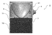
図1は、本実施形態に係るLEDトラック・ライト照明器具1の斜視図であり、図2は、本実施形態に係るLEDトラック・ライト照明器具1の灯具2部分の側断面図である。LEDトラック・ライト照明器具1は、LED発光装置5と、ヒートシンク7、集光部材(リフレクター)6、灯具筐体21等を有する。LED発光装置5、ヒートシンク7、集光部材(リフレクター)6、灯具筐体21等を有する灯具2は、アーム部4により電源ケース3と接続されている。灯具2と電源ケース3との連結角度はアーム部4により調整することができる。
本明細書においては、リフレクター6設けられている側を照明器具1(LEDトラック・ライト照明器具1)の「前方」として定義する。
本明細書においては、リフレクター6設けられている側を照明器具1(LEDトラック・ライト照明器具1)の「前方」として定義する。
LED発光装置5は、ワンコア型のCOBであり、光源として、ヒートシンク底板71の中央部に配置されている。このように配置することにより、LED発光装置5から放出される光は指向性の高い(配光角の狭い)光とすることができるとともに、LED発光装置5で発生する熱を照明器具から放熱することができる。前記ヒートシンク7は、底板71及びその片末端が前記底板に接続された複数の柱状の熱伝導部材72を備えている。
前記底板71の中心領域の最大厚みtcは、前記底板71の外周領域の最小厚みteよりも大きくなっており、ヒートシンク底板71の中心領域に設置されたLED発光装置5で発生した熱が、効率よく、ヒートシンク底板71の外周領域に伝導され、そこから、複数の柱状の熱伝導部材72を通して熱が伝導され、各熱伝導部材72の表面から効率よく放熱される。
COBタイプのLED発光装置5から放射された光は、リフレクター6で反射・集光され指向性の高い(配光角の狭い)光として照明器具の前方に放出される。LED発光装置5は、略放物線回転体形状のリフレクター6の焦点位置付近に設置することにより、光のムラなく、効率的に集光することができる。
COBタイプのLED発光装置5から放射された光は、リフレクター6で反射・集光され指向性の高い(配光角の狭い)光として照明器具の前方に放出される。LED発光装置5は、略放物線回転体形状のリフレクター6の焦点位置付近に設置することにより、光のムラなく、効率的に集光することができる。
本願発明の照明器具は、集光性と光束とを保ちながら小型化・軽量化が可能であり、照明器具(灯具部分)の質量当たりの出射される光束の値が、通常、3.5lumen/g以上であり、好ましくは、4.0lumen/g以上であり、さらに好ましくは、5.0lumen/g以上である。また、照明器具(灯具部分)から出射される光の1/2ビーム角は、好ましくは、5°以上、50°以下、より好ましくは40°以下であり、さらに好ましくは25°以下、よりさらに好ましくは15°以下である。
本願発明の照明器具は、集光性と光束とを保ちながら小型化・軽量化が可能であるので、スポットライト用途に好適に用いられる。
本願発明の照明器具は、集光性と光束とを保ちながら小型化・軽量化が可能であるので、スポットライト用途に好適に用いられる。
(LED発光装置)
LED発光装置5は、モジュール基板の中央部にLEDチップを集約配置した、一つの発光面のみから光を放出する単一光源である、ワンコア(ひと粒)型のモジュールを単一使用することが好ましい。このようなワンコアのLED光源(半導体発光装置)を採用することで、LED照明装置全体として点光源とすることができる。また、このようなワンコアのLED光源を採用することで、マルチシャドウを有効に解消又は緩和することができ、光ムラの少ない均一で安定した照明効果を実現することができる。ワンコア型のモジュールとしては、1又は複数のLEDチップをモジュール基板の実装面に設けた配線上に直接実装するCOB構造が好適に用いられる。
LEDチップを実装するためのモジュール基板としては、例えば、熱伝導性が良好なアルミニウム等の金属材料、或いは絶縁材料等により形成されたメタルベース基板が好適に用いられる。
LED発光装置5は、モジュール基板の中央部にLEDチップを集約配置した、一つの発光面のみから光を放出する単一光源である、ワンコア(ひと粒)型のモジュールを単一使用することが好ましい。このようなワンコアのLED光源(半導体発光装置)を採用することで、LED照明装置全体として点光源とすることができる。また、このようなワンコアのLED光源を採用することで、マルチシャドウを有効に解消又は緩和することができ、光ムラの少ない均一で安定した照明効果を実現することができる。ワンコア型のモジュールとしては、1又は複数のLEDチップをモジュール基板の実装面に設けた配線上に直接実装するCOB構造が好適に用いられる。
LEDチップを実装するためのモジュール基板としては、例えば、熱伝導性が良好なアルミニウム等の金属材料、或いは絶縁材料等により形成されたメタルベース基板が好適に用いられる。
COBタイプのLED発光装置5は、例えば、1又は複数の青色LEDチップをモジュール基板の実装面に設けた配線上に直接実装するCOB構造であり、青色LEDチップにより励起されて発光する、緑色蛍光体及び赤色蛍光体が混ぜ込まれた透光性樹脂によってポッティング等されることにより構成されている。なお、LEDチップは、青色LEDチップのみならず、近紫外LEDチップ等の種々のLEDチップを用いることができ、用いるLEDチップに応じて種々の蛍光体を選択することができる。また、本実施形態におけるLEDチップは、サファイア基板を有しているものを用いることができるが、GaN(窒化ガリウム、ガリウムナイトライド)基板を有しているものも用いることができる。このように、GaN基板を用いたLEDチップを適用した場合、大電流を投入することができ、大光束の点光源を実現することができる。
LED発光装置5は、COB構造を用いる代わりに、パッケージ構造を採用することもでき、種々の形態に適用することができる。また、LED発光装置5は、複数の半導体発光装置をモジュール基板上に分散して配置することもできる。小型のパッケージ構造のLED発光装置5を密接して配置することにより、COBタイプのLED発光装置と同等に近い特性を出すことができる。
また、LEDチップには、サファイア基板以外の基板、例えばGaN基板、シリコン基板などを適用してもよい。
また、LEDチップには、サファイア基板以外の基板、例えばGaN基板、シリコン基板などを適用してもよい。
(ヒートシンク)
図3は、本発明の実施形態に係る照明器具に用いられるヒートシンク(フィンタイプ)の側面図(A)および斜視図(B)である。
ヒートシンク7は、底板71及びその片末端が前記底板71に接続された複数の平板状の熱伝導部材73を備えている。LED発光装置は、前記底板71の熱伝導部材接続面とは反対側の面の中心領域に設置されるように設計されている。ここで、中心領域とは、円の中心部分のように、当該設置面の中心的領域を含む領域であり、具体的にはLED設置領域の直上の領域であって、LED発光装置で発生する熱の外周領域への熱伝導性に優れている領域である。また、中心領域は、集光部材によりLED発光装置から放出される光を集光するにあたって、光のムダなく、ムラなく集光することのできる領域である。例えば、所望する1/2ビーム角にもよるが、概して、底板71が円形の場合には、円の中心点から、その円の直径の半分以内の範囲を意味する。
図3は、本発明の実施形態に係る照明器具に用いられるヒートシンク(フィンタイプ)の側面図(A)および斜視図(B)である。
ヒートシンク7は、底板71及びその片末端が前記底板71に接続された複数の平板状の熱伝導部材73を備えている。LED発光装置は、前記底板71の熱伝導部材接続面とは反対側の面の中心領域に設置されるように設計されている。ここで、中心領域とは、円の中心部分のように、当該設置面の中心的領域を含む領域であり、具体的にはLED設置領域の直上の領域であって、LED発光装置で発生する熱の外周領域への熱伝導性に優れている領域である。また、中心領域は、集光部材によりLED発光装置から放出される光を集光するにあたって、光のムダなく、ムラなく集光することのできる領域である。例えば、所望する1/2ビーム角にもよるが、概して、底板71が円形の場合には、円の中心点から、その円の直径の半分以内の範囲を意味する。
ヒートシンク7の底板71の中心領域の最大厚みをtc、前記底板71の外周領域の最小厚みをteとしたときに、tc/te≧1.2であり、好ましくは、tc/te≧1.5である。ここで、外周領域とは、底板71の中心領域を除く部分であり、LED発光装置の設置されていない領域である。これにより、ヒートシンク底板71の中心領域に設置されたLED発光装置で発生した熱が、効率よく、ヒートシンク底板71の外周領域に伝導され、そこから、複数の平板状あるいは柱状の熱伝導部材を通して熱が伝導され、各熱伝導部材の表面から効率よく放熱される。
中心領域および外周領域の厚みは、一定となる領域を有していてもよいし、連続的に変化していてもよい。また、底板の中心点から底板端部までの距離が一定となるように、厚みが連続的に変化していてもよい。その際、前記底板において前記熱伝導部材が接続されている面(以下、接続面と称する場合がある)が、平面または凸面であることが好ましく、凸面であることがより好ましい。接続面が平面または凸面であることにより、外周領域の熱伝導部材の長さを十分に確保することができ、放熱効率をより高くすることができる。
例えば、底板の断面形状において、接続面が略半球形状である場合には、底板における熱伝導が均一に起こり、かつ、外周領域の熱伝導部材の長さが十分に確保できることから放熱効率が特に高いと推察される。
例えば、底板の断面形状において、接続面が略半球形状である場合には、底板における熱伝導が均一に起こり、かつ、外周領域の熱伝導部材の長さが十分に確保できることから放熱効率が特に高いと推察される。
図4は、本発明の実施形態に係る照明器具に用いられるヒートシンク(ピンタイプ)の断面図(A)および斜視図(B)である。ヒートシンク7は、底板71及びその片末端が前記底板71に接続された複数の柱状の熱伝導部材72を備えている。
底板71の断面のLED発光装置設置面、及び/又は、前記設置面の反対面における、外縁部から中心部に向けての微小区間での傾きの総和が正であることが好ましい。これにより、底板71の中心領域の熱を効率よく外周領域を通して熱伝導部材72に伝達することができ、放熱効率を高めることができる。
底板71の断面のLED発光装置設置面、及び/又は、前記設置面の反対面における、外縁部から中心部に向けての微小区間での傾きの総和が正であることが好ましい。これにより、底板71の中心領域の熱を効率よく外周領域を通して熱伝導部材72に伝達することができ、放熱効率を高めることができる。
ヒートシンク底板71内部に存在する空間が、好ましくは30%以下、より好ましくは20%以下、さらに好ましくは10%以下であることが好ましく、ヒートシンク底板71内部が、完全に中実構造であることがさらに好ましい。これにより、底板71の中心領域の熱を効率よく外周領域を通して熱伝導部材72に伝達することができ、放熱効率を高めることができる。
柱状又は平板状の熱伝導部材の底板71のLED発光装置設置面からの最大高さをhpとしたときに、hp/tc≧1.2であることが放熱の観点から好ましく、hp/tc≧1.5であることがさらに好ましく、hp/tc≧2.0であることがよりさらに好ましい。下限値以上であると、中心領域及び外周領域における熱伝導部材への熱伝導の差が小さくなり、外周領域の熱伝導部材の放熱がより向上するという観点で好ましい。
また、前記複数の柱状又は平板状の熱伝導部材の外観が略円柱形状であることが、放熱の観点から好ましい。平板状の熱伝導部材73はどのような向きに配置されていてもよいが、放熱効率の観点から、平板同士が平行となる向きに配置される、または平板が放射状に配置されてもよい。
また、前記複数の柱状又は平板状の熱伝導部材の外観が略円柱形状であることが、放熱の観点から好ましい。平板状の熱伝導部材73はどのような向きに配置されていてもよいが、放熱効率の観点から、平板同士が平行となる向きに配置される、または平板が放射状に配置されてもよい。
LED発光装置の発熱による最大温度領域は、放熱の観点からヒートシンク底板の中心領域内にあることが好ましい。
また、ヒートシンクの熱伝導率が、放熱の観点から400W/(m・K)以下であり、20W/(m・K)以上であることが好ましく、さらに好ましくは50W/(m・K)以上である。
ヒートシンクの材料は、放熱の観点から金属又は窒化ホウ素であることが好ましい。また金属としては、アルミニウム、又は、銅、あるいはこれらの合金が好ましい。
また、ヒートシンクの熱伝導率が、放熱の観点から400W/(m・K)以下であり、20W/(m・K)以上であることが好ましく、さらに好ましくは50W/(m・K)以上である。
ヒートシンクの材料は、放熱の観点から金属又は窒化ホウ素であることが好ましい。また金属としては、アルミニウム、又は、銅、あるいはこれらの合金が好ましい。
LED発光装置の対角最大長をLE、底板の対角最大長をLBとしたときに、LE/LBは、放熱の観点から、0.7以下であることが好ましい。
また、底板の対角最大長LBが、40mm以上であることが、放熱の観点から好ましい。
底板の中心部を含む断面の形は、特に制限はないが、放熱性および集光性の観点から五角形、多角形、及び、凸型曲線を含む形の群から選ばれるいずれか1つであることが好ましい。
また、底板の対角最大長LBが、40mm以上であることが、放熱の観点から好ましい。
底板の中心部を含む断面の形は、特に制限はないが、放熱性および集光性の観点から五角形、多角形、及び、凸型曲線を含む形の群から選ばれるいずれか1つであることが好ましい。
(集光部材)
本発明に用いられる集光部材は、LED発光装置そのものの配光よりも狭い範囲に配向を制御するための部材であり、例えばLED発光装置から出射される光の1/2ビーム角が120°~150°であるところ、集光部材を用いて1/2ビーム角が5°~60°となる光を出射する照明器具とすることができる。集光部材として、具体的には、リフレクター又はレンズであることが好ましい。
リフレクターは、略放物線回転体形状であることが好ましい。そして、LED発光装置が、略放物線回転体形状のリフレクターの焦点位置に設置されていることが、集光性の観点から好ましい。
また、LED発光装置の発光部分の最大直径をWとした時に、LED発光装置の発光中心が、前記略放物線回転体形状のリフレクターの焦点位置から、好ましくは半径5Wの球体の範囲内に、より好ましくは半径3Wの球体の範囲内に位置することが集光性の観点から好ましい。
本発明に用いられる集光部材は、LED発光装置そのものの配光よりも狭い範囲に配向を制御するための部材であり、例えばLED発光装置から出射される光の1/2ビーム角が120°~150°であるところ、集光部材を用いて1/2ビーム角が5°~60°となる光を出射する照明器具とすることができる。集光部材として、具体的には、リフレクター又はレンズであることが好ましい。
リフレクターは、略放物線回転体形状であることが好ましい。そして、LED発光装置が、略放物線回転体形状のリフレクターの焦点位置に設置されていることが、集光性の観点から好ましい。
また、LED発光装置の発光部分の最大直径をWとした時に、LED発光装置の発光中心が、前記略放物線回転体形状のリフレクターの焦点位置から、好ましくは半径5Wの球体の範囲内に、より好ましくは半径3Wの球体の範囲内に位置することが集光性の観点から好ましい。
レンズは、LED発光装置の前方に位置するように設置されることが好ましい。レンズは、通常、その光軸を中心にした回転体形状を成し、入射面、出射面、側方反射面を備えた構造を有している。また、ワンコア型レンズを用いることが好ましい。ワンコア型レンズとは、光軸を一つだけ有し、出射光に所定の配光角を付与するレンズである。
(灯具筐体)
灯具筐体21は、LED発光装置5、ヒートシンク7、リフレクター6等の集光部材を収納し、保護する役割を果たす。
側方のアーム部4を通して電源ケース3と接続する態様をとることができる。これにより、照明器具の天井等への設置が容易になり、また灯具からの光の照射方向をフレキシブルに調整することが可能になる。
灯具筐体21は、LED発光装置5、ヒートシンク7、リフレクター6等の集光部材を収納し、保護する役割を果たす。
側方のアーム部4を通して電源ケース3と接続する態様をとることができる。これにより、照明器具の天井等への設置が容易になり、また灯具からの光の照射方向をフレキシブルに調整することが可能になる。
(電源ケース)
電源ケース3は電源を収納し、アーム部4を通して灯具筐体21と接続されている。電源ケース3は、通常、天井等への固定ができるように構成されている。
電源ケース3は電源を収納し、アーム部4を通して灯具筐体21と接続されている。電源ケース3は、通常、天井等への固定ができるように構成されている。
(参考例)
図5及び表1は、本発明の実施形態に係る照明器具のヒートシンク底板の中心部の厚みの増加分とヒートシンクのCOBタイプのLED発光装置の設置面の温度との関係を示している。本結果は、Solidworks Flow Simulationを用いて計算した。LED発光装置の発熱量を36Wとし、放熱シート(熱伝導率:1W/m・K)を介して、ヒートシンクに設置しているモデルを作成した。ヒートシンクの形状は、直径63mm、高さ67mmとし、底板に直径3mmの円柱状の熱伝導部材を99本設けてある。ヒートシンクの熱伝導率は92W/m・Kとし、LED発光装置の発熱後、各部材の温度が平衡状態に達した時点でのヒートシンクのLED発光装置の設置面最大温度を評価した。
図5及び表1は、本発明の実施形態に係る照明器具のヒートシンク底板の中心部の厚みの増加分とヒートシンクのCOBタイプのLED発光装置の設置面の温度との関係を示している。本結果は、Solidworks Flow Simulationを用いて計算した。LED発光装置の発熱量を36Wとし、放熱シート(熱伝導率:1W/m・K)を介して、ヒートシンクに設置しているモデルを作成した。ヒートシンクの形状は、直径63mm、高さ67mmとし、底板に直径3mmの円柱状の熱伝導部材を99本設けてある。ヒートシンクの熱伝導率は92W/m・Kとし、LED発光装置の発熱後、各部材の温度が平衡状態に達した時点でのヒートシンクのLED発光装置の設置面最大温度を評価した。

ヒートシンク底板の中心部の厚みを3mmから厚くしていった場合、初めの15mm程度までは、温度低下は大きいが、20mm以上では、あまり変化しなくなる傾向がみられた。
また、ヒートシンク底板の中心厚みを20mm増加させた場合、LED発光装置の設置面温度は、108℃から98℃に低下し、約10℃の改善が見られた。
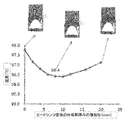
図6及び表2は、本発明の実施形態に係る照明器具のヒートシンク底板の外周部の厚みの増加分とヒートシンクのLED発光装置の設置面の温度との関係を示している。
また、ヒートシンク底板の中心厚みを20mm増加させた場合、LED発光装置の設置面温度は、108℃から98℃に低下し、約10℃の改善が見られた。
図6及び表2は、本発明の実施形態に係る照明器具のヒートシンク底板の外周部の厚みの増加分とヒートシンクのLED発光装置の設置面の温度との関係を示している。

ヒートシンク底板の中心部厚みを20mmとして、外周部の厚みに関して最適化を行った。その結果、外周部の厚みに関しては、8mm~10mm程度の位置に最適点が見られた。
ヒートシンク底板中心部の厚みを20mmとし、外周部の厚みを8mm増加させることで、LED発光装置の設置面の温度は、108℃から96℃に低下し、約12℃の改善が見られた。
ヒートシンク底板中心部の厚みを20mmとし、外周部の厚みを8mm増加させることで、LED発光装置の設置面の温度は、108℃から96℃に低下し、約12℃の改善が見られた。
本発明を詳細にまた特定の実施態様を参照して説明したが、本発明の精神と範囲を逸脱することなく様々な変更や修正を加えることができることは当業者にとって明らかである。本出願は2016年2月9日出願の日本特許出願(特願2016-022778)に基づくものであり、その内容はここに参照として取り込まれる。
1 照明器具
2 灯具
21 灯具筐体
3 電源ケース
4 アーム部
5 LED発光装置
6 リフレクター
7 ヒートシンク
71 底板
72 熱伝導部材(柱状)
73 熱伝導部材(平板状)
2 灯具
21 灯具筐体
3 電源ケース
4 アーム部
5 LED発光装置
6 リフレクター
7 ヒートシンク
71 底板
72 熱伝導部材(柱状)
73 熱伝導部材(平板状)
Claims (17)
- LED発光装置、前記LED発光装置が接続されたヒートシンク、及び前記LED発光装置そのものの配光よりも狭い範囲に配向を制御するための集光部材を備えた照明器具であって、
前記ヒートシンクは、底板及びその片末端が前記底板に接続された複数の柱状又は平板状の熱伝導部材を備えており、
前記LED発光装置は、前記底板の中心領域に設置され、
前記底板の中心領域の最大厚みをtc、前記底板の外周領域の最小厚みをteとしたときに、tc/te≧1.2である照明器具。 - 前記底板において前記熱伝導部材が接続されている面が、平面または凸面である、請求項1に記載の照明器具。
- 前記底板の断面のLED発光装置設置面、及び/又は、前記設置面の反対面における、外縁部から中心部に向けての微小区間での傾きの総和が正である、請求項1又は2に記載の照明器具。
- 前記底板内部に存在する空間が30%以下である、請求項1~3のいずれか1項に記載の照明器具。
- 前記柱状又は平板状の熱伝導部材の底板のLED発光装置設置面からの最大高さをhpとしたときに、hp/tc≧1.2である、請求項1~4のいずれか1項に記載の照明器具。
- 前記複数の柱状又は平板状の熱伝導部材の外観が略円柱形状である、請求項1~5のいずれか1項に記載の照明器具。
- 前記LED発光装置の発熱による最大温度領域が、前記底板の中心領域内にある、請求項1~6のいずれか1項に記載の照明器具。
- 前記ヒートシンクの熱伝導率が、20W/(m・K)以上400W/(m・K)以下である、請求項1~7のいずれか1項に記載の照明器具。
- 前記ヒートシンクの材料が、金属又は窒化ホウ素である、請求項1~8のいずれか1項に記載の照明器具。
- 前記LED発光装置の対角最大長をLE、前記底板の対角最大長をLBとしたときに、LE/LBが0.7以下である、請求項1~9のいずれか1項に記載の照明器具。
- 前記底板の対角最大長LBが、40mm以上である、請求項1~10のいずれか1項に記載の照明器具。
- 前記底板の中心部を含む断面の形が、五角形、多角形、及び、凸型曲線を含む形の群から選ばれるいずれか1つである、請求項1~11のいずれか1項に記載の照明器具。
- 前記LED発光装置が、COBタイプの発光装置である、請求項1~12のいずれか1項に記載の照明器具。
- 前記集光部材が、リフレクター又はレンズである、請求項1~13のいずれか1項に記載の照明器具。
- 前記リフレクターが、略放物線回転体形状である、請求項14に記載の照明器具。
- 前記LED発光装置が、前記略放物線回転体形状のリフレクターの焦点位置に設置されている、請求項15に記載の照明器具。
- 前記LED発光装置の発光部分の最大直径をWとした時に、前記LED発光装置の発光中心が、前記略放物線回転体形状のリフレクターの焦点位置から半径5Wの球体の範囲内に位置する、請求項15又は16に記載の照明器具。
Priority Applications (4)
| Application Number | Priority Date | Filing Date | Title |
|---|---|---|---|
| CN201790000577.XU CN209196807U (zh) | 2016-02-09 | 2017-02-07 | 照明器具 |
| JP2017566962A JPWO2017138538A1 (ja) | 2016-02-09 | 2017-02-07 | 照明器具 |
| DE212017000067.8U DE212017000067U1 (de) | 2016-02-09 | 2017-02-07 | Beleuchtungseinrichtung |
| US16/058,327 US20190003696A1 (en) | 2016-02-09 | 2018-08-08 | Lighting equipment |
Applications Claiming Priority (2)
| Application Number | Priority Date | Filing Date | Title |
|---|---|---|---|
| JP2016-022778 | 2016-02-09 | ||
| JP2016022778 | 2016-02-09 |
Related Child Applications (1)
| Application Number | Title | Priority Date | Filing Date |
|---|---|---|---|
| US16/058,327 Continuation US20190003696A1 (en) | 2016-02-09 | 2018-08-08 | Lighting equipment |
Publications (1)
| Publication Number | Publication Date |
|---|---|
| WO2017138538A1 true WO2017138538A1 (ja) | 2017-08-17 |
Family
ID=59563371
Family Applications (1)
| Application Number | Title | Priority Date | Filing Date |
|---|---|---|---|
| PCT/JP2017/004455 Ceased WO2017138538A1 (ja) | 2016-02-09 | 2017-02-07 | 照明器具 |
Country Status (5)
| Country | Link |
|---|---|
| US (1) | US20190003696A1 (ja) |
| JP (1) | JPWO2017138538A1 (ja) |
| CN (1) | CN209196807U (ja) |
| DE (1) | DE212017000067U1 (ja) |
| WO (1) | WO2017138538A1 (ja) |
Families Citing this family (1)
| Publication number | Priority date | Publication date | Assignee | Title |
|---|---|---|---|---|
| FR3105361B1 (fr) * | 2019-12-20 | 2022-07-15 | Valeo Iluminacion Sa | Echangeur thermique pour composants électroniques |
Citations (2)
| Publication number | Priority date | Publication date | Assignee | Title |
|---|---|---|---|---|
| JP2011113814A (ja) * | 2009-11-26 | 2011-06-09 | Toshiba Lighting & Technology Corp | 照明器具 |
| JP2015090761A (ja) * | 2013-11-05 | 2015-05-11 | 市光工業株式会社 | 車両用灯具 |
Family Cites Families (5)
| Publication number | Priority date | Publication date | Assignee | Title |
|---|---|---|---|---|
| US20070188993A1 (en) * | 2006-02-14 | 2007-08-16 | Gallina Mark J | Quasi-radial heatsink with rectangular form factor and uniform fin length |
| US8430523B1 (en) * | 2009-12-15 | 2013-04-30 | Whelen Engineering Company, Inc. | Asymmetrical optical system |
| WO2014119169A1 (ja) | 2013-01-29 | 2014-08-07 | 三菱化学株式会社 | Led照明装置 |
| JP2014067728A (ja) | 2013-12-17 | 2014-04-17 | Starlite Co Ltd | 自動車用ledランプ |
| JP6102847B2 (ja) | 2014-07-17 | 2017-03-29 | マツダ株式会社 | 車両の制御装置 |
-
2017
- 2017-02-07 WO PCT/JP2017/004455 patent/WO2017138538A1/ja not_active Ceased
- 2017-02-07 DE DE212017000067.8U patent/DE212017000067U1/de not_active Expired - Lifetime
- 2017-02-07 JP JP2017566962A patent/JPWO2017138538A1/ja active Pending
- 2017-02-07 CN CN201790000577.XU patent/CN209196807U/zh not_active Expired - Fee Related
-
2018
- 2018-08-08 US US16/058,327 patent/US20190003696A1/en not_active Abandoned
Patent Citations (2)
| Publication number | Priority date | Publication date | Assignee | Title |
|---|---|---|---|---|
| JP2011113814A (ja) * | 2009-11-26 | 2011-06-09 | Toshiba Lighting & Technology Corp | 照明器具 |
| JP2015090761A (ja) * | 2013-11-05 | 2015-05-11 | 市光工業株式会社 | 車両用灯具 |
Also Published As
| Publication number | Publication date |
|---|---|
| US20190003696A1 (en) | 2019-01-03 |
| CN209196807U (zh) | 2019-08-02 |
| JPWO2017138538A1 (ja) | 2018-11-29 |
| DE212017000067U1 (de) | 2018-10-15 |
Similar Documents
| Publication | Publication Date | Title |
|---|---|---|
| JP5186875B2 (ja) | 照明ユニット | |
| US9004724B2 (en) | Reflector (optics) used in LED deco lamp | |
| JP6244893B2 (ja) | Led照明装置 | |
| CN102261589B (zh) | 照明led灯 | |
| CN104676315A (zh) | 内反射灯具 | |
| JP4683013B2 (ja) | 発光装置 | |
| US7520640B1 (en) | LED wall lamp with a heat sink | |
| CN110748805B (zh) | 一种照明光源系统 | |
| JP5898881B2 (ja) | 照明装置 | |
| WO2013145049A1 (ja) | ランプ | |
| WO2017138538A1 (ja) | 照明器具 | |
| KR101843505B1 (ko) | 엘이디 램프 | |
| EP3315855A1 (en) | Cob lighting device having improved light-distribution, illuminance, and heat -dissipation efficiency | |
| JP2010244688A (ja) | 半導体発光装置の光源モジュールを用いた照明装置 | |
| KR101214378B1 (ko) | Led 조명장치 | |
| JP5742629B2 (ja) | 発光装置及びこれを備えた照明器具 | |
| CN102954378A (zh) | 高光功率密度led光源模块 | |
| JP2012004090A (ja) | 発光ダイオード照明装置 | |
| TWI409406B (zh) | 發光二極體燈具 | |
| TWI442004B (zh) | 光源模組 | |
| CN203812916U (zh) | 发光模块及照明装置 | |
| TWI692597B (zh) | 燈具散熱裝置 | |
| JP2015133450A (ja) | 発光装置、照明用光源、および照明装置 | |
| KR102056299B1 (ko) | 외부 노출형 반사갓을 방열수단으로 하는 led 조명 장치 | |
| JP3204933U (ja) | Ledランプ構造 |
Legal Events
| Date | Code | Title | Description |
|---|---|---|---|
| 121 | Ep: the epo has been informed by wipo that ep was designated in this application |
Ref document number: 17750260 Country of ref document: EP Kind code of ref document: A1 |
|
| ENP | Entry into the national phase |
Ref document number: 2017566962 Country of ref document: JP Kind code of ref document: A |
|
| 122 | Ep: pct application non-entry in european phase |
Ref document number: 17750260 Country of ref document: EP Kind code of ref document: A1 |