WO2017138362A1 - 連続押出機 - Google Patents
連続押出機 Download PDFInfo
- Publication number
- WO2017138362A1 WO2017138362A1 PCT/JP2017/002685 JP2017002685W WO2017138362A1 WO 2017138362 A1 WO2017138362 A1 WO 2017138362A1 JP 2017002685 W JP2017002685 W JP 2017002685W WO 2017138362 A1 WO2017138362 A1 WO 2017138362A1
- Authority
- WO
- WIPO (PCT)
- Prior art keywords
- guide channel
- resin
- continuous extruder
- barrel
- lower guide
- Prior art date
- Legal status (The legal status is an assumption and is not a legal conclusion. Google has not performed a legal analysis and makes no representation as to the accuracy of the status listed.)
- Ceased
Links
Images





Classifications
-
- B—PERFORMING OPERATIONS; TRANSPORTING
- B29—WORKING OF PLASTICS; WORKING OF SUBSTANCES IN A PLASTIC STATE IN GENERAL
- B29C—SHAPING OR JOINING OF PLASTICS; SHAPING OF MATERIAL IN A PLASTIC STATE, NOT OTHERWISE PROVIDED FOR; AFTER-TREATMENT OF THE SHAPED PRODUCTS, e.g. REPAIRING
- B29C48/00—Extrusion moulding, i.e. expressing the moulding material through a die or nozzle which imparts the desired form; Apparatus therefor
- B29C48/25—Component parts, details or accessories; Auxiliary operations
- B29C48/36—Means for plasticising or homogenising the moulding material or forcing it through the nozzle or die
- B29C48/50—Details of extruders
- B29C48/76—Venting, drying means; Degassing means
Definitions
- the present invention relates to a continuous extruder that reduces noise generated inside a barrel.
- a continuous extruder is known as a device for kneading a thermoplastic resin material such as PE (polyethylene) or PP (polypropylene) while melting and continuously extruding the kneaded resin.
- this continuous extruder is rotatably provided with two kneading rotors (kneading screws) for kneading resin in a barrel having a hollow inside.
- a gas body such as water vapor or gas may be generated from the resin material kneaded in the barrel of the continuous extruder.
- the barrel of a general continuous extruder is provided with an open vent for discharging a gas body generated from a resin material to the outside of the barrel so as to penetrate the inside and outside of the barrel.
- an open vent of the continuous extruder is provided with a molten resin overflow suppression mechanism as shown in Patent Document 1 below.
- the extruder of Patent Document 1 is provided with a plurality of sensors for detecting the pressure in the barrel in the vicinity of the granulating device and the open vent inside the barrel containing the kneading rotor, and detected by the plurality of sensors. Based on the pressure of the resin material, the molten resin overflows from the open vent (vent up).
- Patent Document 2 discloses a noise reduction technique that attenuates noise by guiding noise generated in an internal combustion engine such as an automobile to a plurality of noise reduction chambers partitioned by a partition plate, although this is not a technique related to an extruder. ing.
- the present invention has been made in view of the above-described problems, and an object thereof is to provide a continuous extruder that can maintain a good silencing effect even when a resin material overflows from an open vent.
- the continuous extruder of the present invention employs the following technical means. That is, the continuous extruder of the present invention is a continuous extruder having an open vent on the middle side in the longitudinal direction of the barrel and kneading resin, and the open vent has noise generated inside the barrel.
- the noise reduction member is attached to the upper guide flow path for guiding the gas body generated inside the barrel to the upper side of the barrel, and the resin overflowing from the barrel inside the barrel.
- a lower guide channel for guiding the upper guide channel, and an upper end opening of the upper guide channel is installed so as to be positioned above the operator.
- the upper end opening of the upper guide channel is open upward.
- the lower guide channel is formed to be inclined downward with respect to a floor surface on which the continuous extruder is installed.
- the lower guide channel is provided with a resin heating member that heats the resin guided in the lower guide channel and maintains fluidity.
- the resin heating member may have a structure for transferring heat of the barrel to the lower guide channel.
- the resin heating member may include a heater for heating the lower guide channel.
- a resin storage part for storing the resin guided in the lower guide channel is provided at the lower end of the lower guide channel.
- a plurality of the resin reservoirs are provided, a lower end of the lower guide channel is branched into a plurality, and the resin reservoirs are respectively provided at the lower ends of the lower guide channels branched into the plurality. It is preferable that a switching valve for switching the resin guide destination is provided at a branch position of the lower guide channel.
- the resin reservoir is attached to the lower guide channel in a sealed state.
- the upper guide channel may be provided with a meandering portion in which a part of the upper guide channel is meandered.
- the upper guide channel is provided with an inclined portion in which a part of the upper guide channel is inclined upward.
- a silencer using a metal porous plate is attached to the upper guide channel.
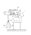
- FIG. 1 schematically shows a continuous extruder 1 according to the first embodiment.
- the continuous extruder 1 of the first embodiment includes a barrel 2 having a hollow inside, and a pair of kneading screws 3 accommodated in the barrel 2. Both the barrel 2 and the kneading screw 3 are formed in a long shape, and are arranged so that the axis is directed in the horizontal direction.
- the right side of the paper surface of FIG. 1 is the upstream side when describing the continuous extruder 1
- the left side of the paper surface is the downstream side.
- the left-right direction of the paper surface of FIG. 1 be the axial direction at the time of explaining the continuous extruder 1.
- the barrel 2 is a member formed in a long cylindrical shape along the horizontal direction, and is supported above the floor surface F on which the operator U works by a support frame.
- the inside of the barrel 2 is a glasses-shaped cavity whose cross section cut in the direction perpendicular to the axis is such that two arcs are connected.
- a kneading screw 3 can be accommodated in the cavity inside the barrel 2, and a material can be supplied between the kneading screw 3 and the inner wall surface of the barrel 2 for kneading.
- a hopper 4 for supplying material into the barrel 2 is provided on the upstream side (one side) of the barrel 2 in the axial direction. Further, a die (not shown) that pushes the kneaded material out of the barrel 2 is provided on the downstream side (the other side) in the axial direction of the barrel 2. In the continuous extruder 1, strands and pellets can be produced by cooling and cutting the material extruded from the die.
- An open vent 5 is provided for exhausting extra gas generated from the material, moisture (water vapor), and the like out of the barrel 2.
- the open vent 5 is an opening that opens upward from the upper surface of the barrel 2.
- a flow hole 6 for guiding a gas body and a molten resin material is provided, and the front end (lower end) of the flow hole 6 opens at the inner wall surface of the barrel 2.
- the opening on the inner wall surface side of the barrel 2 in the flow hole 6 is not the inner wall surface of the barrel 2 positioned between the pair of kneading screws 3, but the inner wall surface of one barrel 2 of the kneading screws 3 provided side by side. Is provided. That is, the opening on the inner wall surface side is formed in a direction inclined in a tangential direction with respect to the inner wall surface of one barrel 2.
- the flow hole 6 is formed in the direction inclined in the tangential direction with respect to the inner wall surface of one barrel 2 in this way, the direction does not face the upstream side in the circumferential flow of the resin due to the rotation of the rotating kneading screw 3.
- a flow hole 6 can be provided. As a result, overflow of the resin material from the open vent 5 can be suppressed.
- the noise reduction member 7 provided in the continuous extruder 1 of the first embodiment is provided so as to cover the open vent 5 from above with respect to the open vent 5 opening upward. It is a member.
- the noise reduction member 7 according to the first embodiment can discharge the gas body and the resin material discharged to the outside of the barrel 2 through the open vent 5 in different directions.
- the noise reduction member 7 of the first embodiment overflows from the inside of the barrel 2 and the duct-shaped upper guide flow path 8 that guides the gas body generated inside the barrel 2 to the upper side of the barrel 2. It has a duct-shaped lower guide passage 9 for guiding the resin to the bottom of the barrel 2.
- the upper guide channel 8 is a cylindrical member that extends straight upward from the open vent 5.
- the upper guide channel 8 guides a gas body such as water vapor and gas from the lower side through the hollow inner side, and the noise generated in the barrel 2 passes through the hollow inner side. Can be guided to.
- the lower end of the upper guide channel 8 is connected to the open vent 5 described above. Further, the upper end of the upper guide channel 8 is provided at a position moved further upward than the open vent 5 so that the gas body and noise can be discharged to the outside from the upper end opening opened upward. It has become.
- the lower guide channel 9 is a channel branched from the middle in the vertical direction of the upper guide channel 8 described above. Unlike the upper guide channel 8 extending upward, the lower guide channel 9 extends downward. ing.
- the lower guide channel 9 is a cylindrical member having a hollow inside, similar to the upper guide channel 8, and the resin material overflowing through the hollow inner side can be discharged downward. ing.
- the upper end of the lower guide channel 9 is connected to the middle of the upper guide channel 8 in the vertical direction.
- the lower guide channel 9 extends from the middle side of the upper guide channel 8 to a slightly lower side, bends further downward on the outer side of the barrel 2, and the lower end of the lower guide channel 9 is It is located below the barrel 2.
- the lower end of the lower guide channel 9 is opened downward so that the overflowing resin material can be discharged downward.
- the continuous extruder 1 of 1st Embodiment is installed so that the position of the upper end of the upper guide flow path 8 may be located above the operator U, in other words, upper guide flow.
- a feature is that the height H of the opening located at the upper end of the path 8 is higher than the height h of the ear of the operator U.
- the height H of the opening located at the upper end of the upper guide channel 8 is such that it exceeds 2 m from the floor F on which the continuous extruder 1 is installed, and preferably exceeds 2.5 m. It is installed at a certain height.
- the upper end of the upper guide channel 8 is opened upward as described above so that the noise inside the barrel 2 guided upward through the upper guide channel 8 can be released upward. It has become.
- the installation height H of the opening for releasing the noise to the outside is higher than the height h of the ear of the operator U.
- the direction in which noise is emitted is also directed away from the operator U. Therefore, noise generated in the barrel 2 does not enter the ears of the operator U and cause deterioration of the work environment.
- the resin material may compete from the above-described open vent 5 and overflow, and the overflowing resin material enters the lower guide channel 9 from the middle of the upper guide channel 8 and enters the gas. It is quickly discharged through a route other than the body and noise. For this reason, the resin material does not accumulate around the open vent 5, and the excellent silencing effect is not hindered by the overflowing resin material.
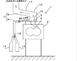
- the lower guide channel 9 described above is formed in an inclined shape downward with respect to the floor surface F on which the continuous extruder 1 is installed. It is characterized by having.
- the continuous extruder 1 of the second embodiment is inclined with respect to the horizontal direction so that the lower guide channel 9 on the side close to the upper guide channel 8 becomes lower as the distance from the upper guide channel 8 increases. It has become.
- the lower guide channel 9 can naturally guide the resin material guided to the lower guide channel 9 downward using its gravity.
- a guide member 10 that guides the resin material to the lower guide channel 9 while allowing the gas body to move upward is provided at a location where the upper guide channel 8 is connected to the lower guide channel 9.
- the guide member 10 is an inclined member provided around the open vent 5.
- the guide member 10 is arranged in an inclined state at substantially the same angle as the above-described lower guide channel 9 so that the resin material of the upper guide channel 8 can be guided to the lower guide channel 9 along the inclined surface. It has become.
- the resin material of the upper guide channel 8 overflowing from the open vent 5 can be guided to the lower guide channel 9 without stagnation. It is possible to reliably suppress clogging of the resin material. Therefore, in the continuous extruder 1 of the second embodiment, the resin material is more difficult to collect around the open vent 5. Therefore, the noise reduction effect can be exhibited for a long time.
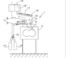
- the continuous extruder 1 of the third embodiment maintains fluidity by heating the resin material guided to the lower guide channel 9 to the above-described lower guide channel 9.
- the resin heating member 11 is provided. Specifically, various means can be used as the resin heating member 11 for heating the resin material.
- a heat transfer member 12 having a structure for transferring the heat of the barrel 2 to the lower guide channel 9 may be used as the resin heating member 11, as shown in FIG. 4, a heat transfer member 12 having a structure for transferring the heat of the barrel 2 to the lower guide channel 9 may be used.
- the heat transfer member 12 is made of a metal having excellent thermal conductivity such as copper or aluminum.
- the end of the heat-transfer member 12 is attached in the state which can transfer the heat of the barrel 2 to heat. That is, the heat transfer member 12 and the barrel 2 are directly connected so that other members do not enter between them using welding or bolts, and the heat of the barrel 2 can be transferred to the heat transfer member 12. It is in a state of being. Further, the other end of the heat transfer member 12 is in contact with the outer peripheral surface of the lower guide channel 9, and heat of the barrel 2 can be transmitted to the lower guide channel 9 via the heat transfer member 12.
- the heat of the barrel 2 that has become high temperature by kneading can be transferred to the lower guide channel 9 via the heat transfer member 12.
- the resin material flowing through the lower guide channel 9 can be heated to prevent the resin material from sticking to the lower guide channel 9 and to maintain the fluidity of the resin material.
- the above-described resin heating member 11 may be any means as long as it can heat the resin material.
- a heater 13 for heating the lower guide channel 9 may be provided as a resin heating member 11 on the outer peripheral surface of the lower guide channel 9. Even when such a heater 13 type resin heating member 11 is used, the resin material flowing through the lower guide channel 9 can be heated, and the fluidity of the resin material can be maintained.
- the continuous extruder 1 of 3rd Embodiment while suppressing that the leaked resin adheres in a duct part, it suppresses that a volatile gas and water vapor
- the continuous extruder 1 of 4th Embodiment was provided with the resin storage part 14 which stores the resin material guided by the said lower guide flow path 9 in the lower end of the lower guide flow path 9. As shown in FIG. It has become a thing.
- any container may be used as long as the resin material can be stored.
- a bottomed cylindrical container that opens upward is used as the resin reservoir 14.
- the resin reservoir 14 is provided detachably with respect to the lower end of the lower guide channel 9 and can be replaced with an empty container when it is filled with the resin material.
- a removable resin reservoir 14 such as a cartridge
- the labor of replacing the resin reservoir 14 when collected with a resin material can be greatly reduced.
- the continuous extruder 1 includes a resin reservoir 14 similar to that of the fourth embodiment described above, but unlike the fourth embodiment, the resin reservoir 14. And a plurality of resin reservoirs 14 can receive the resin material.
- the lower guide channel 9 has a lower end branched into a plurality of portions, and a resin storage section 14 is provided at each of the lower guide channels 9 branched into a plurality of branches. It has been.
- a switching valve 15 is provided at the branch position of the lower guide channel 9 to switch the guide destination of the resin material.
- the switching valve 15 is switched to guide the resin material to the other resin reservoir 14. To do. Then, after the changeover valve 15 is switched and the resin material can be guided to the other resin reservoir 14, the one resin reservoir 14 filled with the resin material is replaced with an empty resin reservoir 14 (new resin reservoir 14). Part 14).
- the resin reservoir 14 can be replaced without stopping the operation of the continuous extruder 1 by switching the guide of the resin material with the switching valve 15.
- the productivity of the continuous extruder 1 can be further increased.
- the resin reservoir 14 opens upward, and the lower end of the lower guide channel 9 and the opening of the resin reservoir 14 are hermetically connected. There wasn't.
- the lower end of the lower guide channel 9 and the opening of the resin reservoir 14 are connected so as to maintain airtightness,
- the resin reservoir 14 is attached to the lower guide channel 9 in a sealed state.
- the overflowing resin material can be stored in the sealed resin reservoir 14.
- a connecting means using screwing or fitting is provided between the lower end of the lower guide channel 9 and the opening of the resin reservoir 14, and the interior of the resin reservoir 14 is airtight. It can be maintained in a state.
- the resin reservoir 14 is attached to the lower guide channel 9 in a sealed state in this way, it is possible to suppress leakage of noise from between the lower end of the lower guide channel 9 and the opening of the resin reservoir 14. It becomes.
- the continuous extruder 1 of 7th Embodiment provided the meandering part 16 by which a part of this upper guide flow path 8 meandered in the upper guide flow path 8 mentioned above. ing.
- the meandering portion 16 provided in the continuous extruder 1 of the seventh embodiment is one in which the middle part in the vertical direction in the upper guide channel 8 is bent at least once in the horizontal direction.
- the meandering portion 16 is bent to such an extent that the open vent 5 cannot be directly viewed by the meandering portion 16 when looking downward from an opening located at the upper end of the upper guide channel 8.
- the continuous extruder 1 of the eighth embodiment is provided with a meandering portion 16 similar to that of the seventh embodiment on the middle side of the upper guide flow path 8.
- the meandering portion 16 is provided with an inclined portion 17 inclined upward in the upper guide channel 8.
- the inclined portion 17 of the eighth embodiment inclines the upward guide channel 8 provided in the above-described meandering portion 16 in the upward gradient direction with respect to the horizontal direction as the distance from the open vent 5 increases. It has been made to.
- the gas body and water vapor are cooled when passing through the meandering portion 16, and the component and moisture of the resin that has cooled and liquefied are transferred to the meandering portion 16. May accumulate. If the resin component or moisture accumulates in the meandering portion 16 in this way, the accumulated resin component or moisture may flow back to the open vent 5 and enter the barrel 2 from the open vent 5, which is a manufactured product due to foreign matter contamination. There is a risk of quality deterioration.
- the inclined portion 17 is provided in the meandering portion 16 described above to prevent the resin component and moisture from accumulating in the meandering portion 16, and the accumulated resin component and moisture. This prevents the flow back into the open vent 5.
- the continuous extruder 1 according to the ninth embodiment has a silencer 18 using a metal porous plate 19 attached to the continuous extruder 1 according to the eighth embodiment described above.
- the silencer 18 of the ninth embodiment is a cylindrical member having an inner diameter that is about six times the upper guide flow path 8, and a large number of metal silencers are formed on the surface of the metal plate.
- This is provided with a cylindrical metal perforated plate 19 in which the holes are formed.
- the frequency range in which the silencing effect can be expected can be changed by adjusting the opening diameters of a large number of holes and the distances between the holes.
- the silencer 18 in FIG. 12 can exhibit the silencing characteristics (the relationship between the silencing frequency and the silencing sound pressure) as shown in FIG.
- the frequency analysis (1/3 octave band constant frequency ratio filter shown in FIG. 13 was used. As is clear from the frequency analysis, it can be seen that the loss of sound intensity is maximum near 500 Hz and 1600 Hz, and the noise generated in the barrel 2 is effectively muted.
- the dimensions of the silencer 18 and the upper guide channel 8 used for frequency analysis are as follows. Inner diameter of upper guide channel 8: ⁇ 50mm The inner diameter of the silencer 18: ⁇ 300mm The thickness of the silencer 18 in the height direction: 200 mm Pipe length of the upper guide channel 8 connected to the silencer 18: 200 mm
- the silencer 18 of the ninth embodiment using the metal porous plate 19 is provided in the middle of the upper guide flow path 8, the noise reduction effect around the continuous extruder 1 can be enhanced. It is judged.
- the use of the silencer 18 having the above-described metal porous plate 19 suppresses aging deterioration unlike those formed of urethane or the like, so that the noise reduction effect is achieved. It can be demonstrated over a long period of time.
- embodiment disclosed this time is an illustration and restrictive at no points.
- matters that are not explicitly disclosed, for example, operating conditions and operating conditions, various parameters, dimensions, weights, volumes, and the like of a component deviate from a range that a person skilled in the art normally performs. Instead, values that can be easily assumed by those skilled in the art are employed.
Landscapes
- Engineering & Computer Science (AREA)
- Mechanical Engineering (AREA)
- Extrusion Moulding Of Plastics Or The Like (AREA)
Abstract
本発明の連続押出機は、バレルの長手方向の中途側にオープンベントを備え、且つ、樹脂を混練する。オープンベントには、バレルの内部で発生する騒音を低減する騒音低減部材が取り付けられている。騒音低減部材は、バレルの内部で発生したガス体をバレルの上方に案内する上方案内流路と、バレルの内部から溢れ出る樹脂をバレルの下方に案内する下方案内流路とを有する。上方案内流路の上端開口部は、オペレータより上方に位置するように設置されている。
Description
本発明は、バレルの内部で発生する騒音を低減する連続押出機に関する。
従来より、PE(ポリエチレン)やPP(ポリプロピレン)などの熱可塑性の樹脂材料を溶融しながら混練し、混練された樹脂を連続的に押し出す装置として、連続押出機が知られている。具体的には、この連続押出機は、内部が空洞とされたバレル内に、樹脂を混練する2本の混練ロータ(混練スクリュ)を回転自在に備えている。
ところで、連続押出機のバレル内で混練されている樹脂材料からは、水蒸気やガスなどのガス体が発生することがある。このようなガス体がバレル内に蓄積すると、蓄積されたガス体が混練を阻害する場合がある。それゆえ、一般的な連続押出機のバレルには、樹脂材料から発生するガス体をバレル外に排出するオープンベントが、バレル内外を貫通するように設けられている。
ところで、連続押出機のバレル内で混練されている樹脂材料からは、水蒸気やガスなどのガス体が発生することがある。このようなガス体がバレル内に蓄積すると、蓄積されたガス体が混練を阻害する場合がある。それゆえ、一般的な連続押出機のバレルには、樹脂材料から発生するガス体をバレル外に排出するオープンベントが、バレル内外を貫通するように設けられている。
ただ、このようなオープンベントを設けると、バレル内の圧力が高くなった場合にはオープンベントからガス体だけでなく溶融樹脂が溢れ出る可能性がある。そのため、連続押出機のオープンベントには、次の特許文献1に示すような溶融樹脂の溢出抑制機構が設けられている。
例えば、特許文献1の押出機は、内部に混練ロータを収容したバレルの内部における造粒装置やオープンベント近傍に、バレル内の圧力を検知する複数のセンサを設け、複数のセンサで検知された樹脂材料の圧力に基づいて、オープンベントからの溶融樹脂の溢れ出し(ベントアップ)を予測する構成となっている。
例えば、特許文献1の押出機は、内部に混練ロータを収容したバレルの内部における造粒装置やオープンベント近傍に、バレル内の圧力を検知する複数のセンサを設け、複数のセンサで検知された樹脂材料の圧力に基づいて、オープンベントからの溶融樹脂の溢れ出し(ベントアップ)を予測する構成となっている。
また、特許文献2には、押出機に関する技術ではないものの、自動車などの内燃機関で発生した騒音を、仕切板で仕切られた複数の消音室に導いて、騒音を減衰する消音技術が開示されている。
ところで、特許文献1の連続押出機では、ベントアップによる材料の溢れ出しは抑制できても、オープンベントからの騒音発生は抑制することができない。
また、特許文献1の連続押出機に特許文献2に開示された消音器を設けることも考えられるが、特許文献2に開示された消音器は自動車のエンジンのような気体のみが排気される使用環境での使用を想定したものである。当然、連続押出機のように樹脂が溢れ出るような使用環境での使用は想定しておらず、連続押出機に用いた場合には溢れ出た樹脂材料で通気孔などが目詰まりしてしまい、十分な消音効果を発揮できなくなる可能性がある。
また、特許文献1の連続押出機に特許文献2に開示された消音器を設けることも考えられるが、特許文献2に開示された消音器は自動車のエンジンのような気体のみが排気される使用環境での使用を想定したものである。当然、連続押出機のように樹脂が溢れ出るような使用環境での使用は想定しておらず、連続押出機に用いた場合には溢れ出た樹脂材料で通気孔などが目詰まりしてしまい、十分な消音効果を発揮できなくなる可能性がある。
本発明は、上述の問題に鑑みてなされたものであり、オープンベントから樹脂材料が溢れ出た場合にも、良好な消音効果を維持できる連続押出機を提供することを目的とする。
上記課題を解決するため、本発明の連続押出機は以下の技術的手段を講じている。
即ち、本発明の連続押出機は、バレルの長手方向の中途側にオープンベントを備え、且つ、樹脂を混練する連続押出機であって、前記オープンベントには、前記バレルの内部で発生する騒音を低減する騒音低減部材が取り付けられており、前記騒音低減部材は、前記バレルの内部で発生したガス体をバレルの上方に案内する上方案内流路と、前記バレルの内部から溢れ出る樹脂をバレルの下方に案内する下方案内流路とを有しており、前記上方案内流路の上端開口部が、オペレータより上方に位置するように設置されていることを特徴とする。
即ち、本発明の連続押出機は、バレルの長手方向の中途側にオープンベントを備え、且つ、樹脂を混練する連続押出機であって、前記オープンベントには、前記バレルの内部で発生する騒音を低減する騒音低減部材が取り付けられており、前記騒音低減部材は、前記バレルの内部で発生したガス体をバレルの上方に案内する上方案内流路と、前記バレルの内部から溢れ出る樹脂をバレルの下方に案内する下方案内流路とを有しており、前記上方案内流路の上端開口部が、オペレータより上方に位置するように設置されていることを特徴とする。
好ましくは、前記上方案内流路の上端開口部が、上方に向かって開口しているとよい。
好ましくは、前記下方案内流路は、前記連続押出機が設置される床面に対して下方に向かって傾斜状に形成されているとよい。
好ましくは、前記下方案内流路には、当該下方案内流路に案内された樹脂を加熱して流動性を維持する樹脂加熱部材が設けられているとよい。
好ましくは、前記下方案内流路は、前記連続押出機が設置される床面に対して下方に向かって傾斜状に形成されているとよい。
好ましくは、前記下方案内流路には、当該下方案内流路に案内された樹脂を加熱して流動性を維持する樹脂加熱部材が設けられているとよい。
好ましくは、前記樹脂加熱部材は、前記バレルの熱を前記下方案内流路に伝熱する構造とされているとよい。
好ましくは、前記樹脂加熱部材は、前記下方案内流路を加熱するヒータを備えているとよい。
好ましくは、前記下方案内流路の下端には、当該下方案内流路に案内された樹脂を貯溜する樹脂貯溜部が設けられているとよい。
好ましくは、前記樹脂加熱部材は、前記下方案内流路を加熱するヒータを備えているとよい。
好ましくは、前記下方案内流路の下端には、当該下方案内流路に案内された樹脂を貯溜する樹脂貯溜部が設けられているとよい。
好ましくは、前記樹脂貯溜部は、複数設けられており、前記下方案内流路の下端は、複数に分岐していて、前記複数に分岐した下方案内流路の下端に、前記樹脂貯溜部がそれぞれ設けられており、前記下方案内流路の分岐位置には、前記樹脂の案内先を切り換える切替弁が設けられているとよい。
好ましくは、前記樹脂貯溜部が前記下方案内流路に対して密閉状態で取り付けられているとよい。
好ましくは、前記樹脂貯溜部が前記下方案内流路に対して密閉状態で取り付けられているとよい。
好ましくは、前記上方案内流路には、当該上方案内流路の一部が蛇行されてなる蛇行部が設けられているとよい。
好ましくは、前記上方案内流路には、当該上方案内流路の一部を上方に向かって傾斜させた傾斜部が設けられているとよい。
好ましくは、前記上方案内流路に、金属多孔板を用いた消音器が取り付けられているとよい。
好ましくは、前記上方案内流路には、当該上方案内流路の一部を上方に向かって傾斜させた傾斜部が設けられているとよい。
好ましくは、前記上方案内流路に、金属多孔板を用いた消音器が取り付けられているとよい。
本発明の連続押出機によれば、オープンベントから樹脂材料が溢れ出た場合にも、良好な消音効果を維持できる。
[第1実施形態]
以下、本発明の連続押出機1の実施形態を、図面に基づき詳しく説明する。
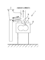
図1は、第1実施形態の連続押出機1を模式的に示したものである。
図1に示すように、第1実施形態の連続押出機1は、内部が空洞とされたバレル2と、このバレル2内に収容される一対の混練スクリュ3と、を備えている。これらのバレル2と混練スクリュ3とは、いずれも長尺に形成されており、水平方向に軸心を向けるようにして配備されている。
以下、本発明の連続押出機1の実施形態を、図面に基づき詳しく説明する。
図1は、第1実施形態の連続押出機1を模式的に示したものである。
図1に示すように、第1実施形態の連続押出機1は、内部が空洞とされたバレル2と、このバレル2内に収容される一対の混練スクリュ3と、を備えている。これらのバレル2と混練スクリュ3とは、いずれも長尺に形成されており、水平方向に軸心を向けるようにして配備されている。
なお、以降の説明において、図1の紙面の右側を連続押出機1を説明する際の上流側とし、紙面の左側を下流側とする。また、図1の紙面の左右方向を連続押出機1を説明する際の軸方向とする。
バレル2は、水平方向に沿って長尺な筒状に形成された部材であり、支持フレームによりオペレータUが作業する床面Fより上方に支持されている。バレル2の内部は軸垂直方向に切断した断面が2つの円弧が連なるようなめがね形状の空洞となっている。このバレル2内部の空洞には、混練スクリュ3が収容可能とされており、また混練スクリュ3とバレル2の内壁面との間に材料を供給して混練ができるようになっている。
バレル2の軸方向の上流側(一方側)にはバレル2内に材料を供給するホッパ4が設けられている。また、バレル2の軸方向の下流側(他方側)には混練された材料をバレル2外へ押し出すダイ(図示略)が備えられている。連続押出機1では、このダイから押し出された材料を冷却・切断することで、ストランドやペレットを製造できるようになっている。
さらに、長手方向の中途側(ダイとホッパ4との間)に位置するバレル2の外周面、言い換えればダイよりやや上流側に位置するバレル2の外周面には、バレル2内で混練された材料から発生する余計なガスや水分(水蒸気)などをバレル2外へ排気するオープンベント5が設けられている。
このオープンベント5は、バレル2の上面から上方に向かって開口する開口部である。オープンベント5の先には、ガス体や溶融した樹脂材料を案内する流通孔6が設けられており、この流通孔6の先端(下端)は、バレル2の内壁面に開口している。なお、流通孔6におけるバレル2の内壁面側の開口は、一対の混練スクリュ3の間に位置するバレル2の内壁面ではなく、並んで設けられた混練スクリュ3の一方のバレル2の内壁面に設けられている。つまり、内壁面側の開口は、一方のバレル2の内壁面に対して接線方向に傾斜した方向に形成されている。このように一方のバレル2の内壁面に対して接線方向に傾斜した方向に流通孔6を形成すれば、回転する混練スクリュ3の回転による、樹脂の周方向流れにおける上流側に対向しない向きに流通孔6を設けることができる。その結果、オープンベント5からの樹脂材料の溢れ出しを抑制することが可能となる。
図2に示すように、第1実施形態の連続押出機1に設けられる騒音低減部材7は、上方に向かって開口するオープンベント5に対して、オープンベント5を上方から覆うように設けられた部材である。第1実施形態の騒音低減部材7は、オープンベント5を通じてバレル2の外部に排出されるガス体と樹脂材料とをそれぞれ別方向にわけて排出できるようになっている。
具体的には、第1実施形態の騒音低減部材7は、バレル2の内部で発生したガス体をバレル2の上方に案内するダクト状の上方案内流路8と、バレル2の内部から溢れ出る樹脂をバレル2の下方に案内するダクト状の下方案内流路9とを有している。
上方案内流路8は、オープンベント5から真っ直ぐ上方に向かって伸びる筒状の部材である。この上方案内流路8は、中空とされた内側を通って水蒸気やガスなどのガス体を下方から上方に案内すると共に、バレル2内で発生した騒音を中空とされた内側を経由して上方に案内できるようになっている。上方案内流路8の下端は、上述したオープンベント5に連結されている。また、上方案内流路8の上端は、オープンベント5よりもさらに上方に移動した位置に設けられていて、上方に向かって開口した上端開口部からガス体と騒音とを外部に排出できるようになっている。
下方案内流路9は、上述した上方案内流路8の上下方向の中途側から分岐した流路であり、上方に向かって伸びる上方案内流路8とは異なり、下方に向かって伸びるものとなっている。この下方案内流路9は、上方案内流路8と同様に内部が中空とされた筒状の部材であり、中空とされた内側を通って溢れ出た樹脂材料を下方に排出できるようになっている。
具体的には、下方案内流路9の上端は、上方案内流路8の上下方向の中途側に連結されている。そして、下方案内流路9は、上方案内流路8の中途側から側方のやや下側に向かって伸び、バレル2のさらに外側で下方に向かって屈曲し、下方案内流路9の下端はバレル2よりも下方に位置している。この下方案内流路9の下端は、下方に向かって開口しており、溢れ出た樹脂材料を下方に排出できるようになっている。
ところで、図1に示すように、第1実施形態の連続押出機1は、上方案内流路8の上端の位置が、オペレータUより上方に位置するように設置されている、言い換えれば上方案内流路8の上端に位置する開口の高さHがオペレータUの耳の高さhより高いものとされていることを特徴としている。
具体的には、上方案内流路8の上端に位置する開口の高さHは、連続押出機1が設置された床面Fから2mを超えるような高さ、好ましくは2.5mを超えるような高さに設置されている。そして、この上方案内流路8の上端は、上述したように上方に向かって開口しており、上方案内流路8を通じて上方に案内されてきたバレル2内部の騒音を上方に向かって放出できるようになっている。
このような高さHに上端が位置する上方案内流路8を採用すれば、騒音を外部に放出する開口の設置高さHがオペレータUの耳の高さhよりも高いものとなる。また、騒音の放出する方向もオペレータUから遠ざかる方向を向くものとなる。そのため、バレル2内で発生した騒音がオペレータUの耳に入って、作業環境の劣化を招くことがなくなる。
また、上述したオープンベント5からは樹脂材料が競り上がってきて溢れ出る場合もあるが、このように溢れ出た樹脂材料は上方案内流路8の中途側から下方案内流路9に入り、ガス体や騒音とは別の経路で速やかに排出される。このため、オープンベント5の周辺に樹脂材料が溜まることがなく、溢れ出た樹脂材料によって良好な消音効果が阻害されることもない。
そのため、第1実施形態の連続押出機1においては、オープンベント5から樹脂材料が溢れ出た場合にも、連続押出機1の設置場所の周辺で良好な騒音低減効果を維持することが可能となる。
[第2実施形態]
次に、第2実施形態の連続押出機1について説明する。
次に、第2実施形態の連続押出機1について説明する。
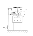
図3に示すように、第2実施形態の連続押出機1は、上述した下方案内流路9が、連続押出機1が設置された床面Fに対して下方に向かって傾斜状に形成されていることを特徴としている。
具体的には、第2実施形態の連続押出機1は、上方案内流路8に近い側の下方案内流路9が、上方案内流路8から離れるに従い低くなるように水平方向に対して傾斜したものとなっている。これにより、下方案内流路9は、下方案内流路9に案内された樹脂材料をその重力を利用して自然に下方に誘導できるようになっている。
また、上方案内流路8における下方案内流路9との接続箇所には、ガス体の上方移動を許容しつつも樹脂材料を下方案内流路9に案内する案内部材10が設けられている。この案内部材10は、オープンベント5の周囲に設けられた傾斜した部材である。案内部材10は、上述した下方案内流路9とほぼ等しい角度で傾斜した状態で配備されていて、傾斜した表面に沿って上方案内流路8の樹脂材料を下方案内流路9に誘導できるようになっている。
上述した第2実施形態の連続押出機1では、オープンベント5から溢れ出た上方案内流路8の樹脂材料を、滞ることなく下方案内流路9に案内することができ、オープンベント5での樹脂材料の詰まりを確実に抑制することが可能となる。それゆえ、第2実施形態の連続押出機1では、オープンベント5の周辺に樹脂材料がより一層たまり難くなる。よって、騒音低減効果を長く発揮させることが可能となる。
[第3実施形態]
次に、第3実施形態の連続押出機1について説明する。
次に、第3実施形態の連続押出機1について説明する。
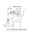
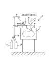
図4及び図5に示すように、第3実施形態の連続押出機1は、上述した下方案内流路9に、この下方案内流路9に案内された樹脂材料を加熱して流動性を維持する樹脂加熱部材11が設けられたものとなっている。
具体的には、この樹脂材料を加熱する樹脂加熱部材11としては、さまざまな手段を用いることができる。
具体的には、この樹脂材料を加熱する樹脂加熱部材11としては、さまざまな手段を用いることができる。
例えば、樹脂加熱部材11としては、図4に示すように、バレル2の熱を下方案内流路9に伝熱する構造の伝熱部材12を用いても良い。この伝熱部材12は、銅やアルミなどの熱伝導性に優れた金属から形成されている。そして、伝熱部材12の一端は、バレル2の熱を熱伝達可能な状態で取り付けられている。つまり、伝熱部材12とバレル2とは溶接やボルトなど手段を用いて両者の間に他の部材が入らないように直接連結されており、バレル2の熱を伝熱部材12に伝熱可能な状態とされている。また、伝熱部材12の他端は、下方案内流路9の外周面に接触しており、伝熱部材12を介してバレル2の熱を下方案内流路9に伝達可能とされている。
このような伝熱部材12を樹脂加熱部材11として用いれば、混練によって高温になっているバレル2の熱を、伝熱部材12を介して下方案内流路9に伝達することができる。また、下方案内流路9を流通する樹脂材料を加熱して、下方案内流路9への樹脂材料の固着を防止すると共に樹脂材料の流動性を維持することが可能となる。
なお、上述した樹脂加熱部材11は、樹脂材料を加熱できるものであれば、どのような手段でも良い。例えば、図5に示すように、下方案内流路9の外周面に、下方案内流路9を加熱するヒータ13を樹脂加熱部材11として設けてもよい。このようなヒータ13方式の樹脂加熱部材11を用いた場合にも、下方案内流路9を流通する樹脂材料を加熱することが可能となり、樹脂材料の流動性を維持することが可能となる。また、第3実施形態の連続押出機1では、漏れ出た樹脂がダクト部で固着することを抑制するとともに、揮発ガスや水蒸気が冷えて液化してベント開口側へ戻ってくるのを抑制することも可能となる。
[第4実施形態]
次に、第4実施形態の連続押出機1について説明する。
次に、第4実施形態の連続押出機1について説明する。
図6に示すように、第4実施形態の連続押出機1は、下方案内流路9の下端に、当該下方案内流路9に案内された樹脂材料を貯溜する樹脂貯溜部14が設けられたものとなっている。
具体的には、この樹脂貯溜部14としては、樹脂材料が貯溜できるものであれば、どのような容器を用いても良い。例えば、図例では、上方に向かって開口した有底筒状の容器を樹脂貯溜部14として用いている。
この樹脂貯溜部14は、下方案内流路9の下端に対して着脱自在に設けられており、樹脂材料で一杯になったら空の容器と取り替え可能となっている。
このようなカートリッジのように着脱自在な樹脂貯溜部14を用いれば、樹脂材料で溜まった際に樹脂貯溜部14を交換する手間を大幅に省くことができる。これにより、樹脂貯溜部14の交換時に連続押出機1を長時間に亘って停止させなくても済むようになって、連続押出機1の生産性を高めることが可能となる。
[第5実施形態]
次に、第5実施形態の連続押出機1について説明する。
次に、第5実施形態の連続押出機1について説明する。
図7に示すように、第5実施形態の連続押出機1は、上述した第4実施形態と同様な樹脂貯溜部14を備えたものであるが、第4実施形態とは異なり樹脂貯溜部14を複数設けたものとなっており、複数の樹脂貯溜部14のそれぞれで樹脂材料を受けることができるようになっている。
具体的には、第5実施形態の連続押出機1は、下方案内流路9の下端が複数に分岐していて、複数に分岐した下方案内流路9の下端に樹脂貯溜部14がそれぞれ設けられている。そして、下方案内流路9の分岐位置には、樹脂材料の案内先を切り換える切替弁15が設けられている。
つまり、第5実施形態の連続押出機1では、複数の樹脂貯溜部14の一方で樹脂材料が一杯になった場合には、切替弁15を切り換えて他方の樹脂貯溜部14に樹脂材料を案内するようにする。そして、切替弁15を切り換えて他方の樹脂貯溜部14に樹脂材料が案内可能とされてから、樹脂材料で一杯になった一方の樹脂貯溜部14を空の樹脂貯溜部14(新たな樹脂貯溜部14)に取り替えるようにする。
このような第5実施形態の連続押出機1では、切替弁15を樹脂材料の案内先を切り替えることで、連続押出機1の運転を停止させることなく、樹脂貯溜部14を交換することができ、連続押出機1の生産性をより一層高めることが可能となる。
[第6実施形態]
次に、第6実施形態の連続押出機1について説明する。
次に、第6実施形態の連続押出機1について説明する。
上述した第1実施形態~第5実施形態では、樹脂貯溜部14は上方に向かって開口しており、下方案内流路9の下端と、樹脂貯溜部14の開口とは気密的に接続されていなかった。
しかし、図8に示すように、第6実施形態の連続押出機1は、下方案内流路9の下端と、樹脂貯溜部14の開口との間は気密性を維持可能に接続されており、樹脂貯溜部14が下方案内流路9に対して密閉状態で取り付けられている。これにより、密閉された樹脂貯溜部14の内部に溢れ出た樹脂材料を溜め込むことが可能とされている。
具体的には、下方案内流路9の下端と、樹脂貯溜部14の開口との間には、螺合や嵌着を用いた連結手段が設けられており、樹脂貯溜部14の内部を気密状態に維持できるようになっている。
このように樹脂貯溜部14を下方案内流路9に対して密閉状態で取り付けておけば、下方案内流路9の下端と樹脂貯溜部14の開口との間からの騒音が漏れることを抑制可能となる。
[第7実施形態]
次に、第7実施形態の連続押出機1について説明する。
次に、第7実施形態の連続押出機1について説明する。
図9に示すように、第7実施形態の連続押出機1は、上述した上方案内流路8に、この上方案内流路8の一部が蛇行されてなる蛇行部16を設けたものとなっている。
具体的には、第7実施形態の連続押出機1設けられる蛇行部16は、上方案内流路8における上下方向の中途側を水平方向に少なくとも1回以上屈曲させたものである。そして、この蛇行部16は、上方案内流路8の上端に位置する開口から下方を覗いた場合に、蛇行部16によってオープンベント5が直視できない程度に屈曲されている。
このような蛇行部16を上方案内流路8の中途側に設ければ、オープンベント5から上方に放出される騒音が、上方案内流路8の上端に位置する開口まで伝搬しにくくなり、連続押出機1の騒音をより一層低減することが可能となる。
[第8実施形態]
次に、第8実施形態の連続押出機1について説明する。
次に、第8実施形態の連続押出機1について説明する。
図10に示すように、第8実施形態の連続押出機1は、第7実施形態と同様な蛇行部16を上方案内流路8の中途側に設けたものであるが、第7実施形態とは異なり上方案内流路8に上方に向かって傾斜した傾斜部17を蛇行部16に備えたものとなっている。
具体的には、この第8実施形態の傾斜部17は、上述した蛇行部16に設けられる上方案内流路8を、オープンベント5から上方に離れるにつれて、水平方向に対して昇り勾配方向に傾斜させたものとなっている。
つまり、上述した蛇行部16のように上方案内流路8を屈曲させると、蛇行部16を通過する際にガス体や水蒸気が冷却され、冷えて液化した樹脂の成分や水分が蛇行部16に溜まる場合がある。このように蛇行部16に樹脂の成分や水分が溜まると、溜まった樹脂の成分や水分がオープンベント5に逆流し、オープンベント5からバレル2内に入る可能性があり、異物混入による製造品の品質悪化を招く虞がある。
それゆえ、第8実施形態の連続押出機1では、上述した蛇行部16に傾斜部17を設けて、蛇行部16に樹脂の成分や水分が溜まることを防止し、溜まった樹脂の成分や水分がオープンベント5に逆流することを抑制しているのである。
[第9実施形態]
次に、第9実施形態の連続押出機1について説明する。
次に、第9実施形態の連続押出機1について説明する。
図11に示すように、第9実施形態の連続押出機1は、上述した第8実施形態の連続押出機1に、金属多孔板19を用いた消音器18が取り付けたものとなっている。
具体的には、この第9実施形態の消音器18は、図12に示すように、上方案内流路8の6倍程度の内径を備えた円筒状の部材であり、金属板の表面に多数の孔部を形成した円筒状の金属多孔板19を備えたものである。この金属多孔板19を用いた消音器18では、多数の孔部の開口径や孔部同士の距離を調整することで、消音効果が期待できる周波域を変更可能となっている。図12の消音器18では、図13に示すような消音特性(消音周波数と消音音圧との関係)を発揮できるようになっている。
そして、実際に図12に示す消音器18を上方案内流路8における蛇行部16の上側に設けた場合には、図13に示す周波数解析(1/3オクターブバンドの定周波数比フィルタを用いた周波数解析)からも明らかなように、500Hz付近及び1600Hz付近で音の強さの損失が最大となっており、バレル2内で発生する騒音が効果的に消音されていることがわかる。
なお、周波数解析に用いた消音器18と上方案内流路8の寸法は次の通りである。
上方案内流路8の内径:φ50mm
消音器18の内径:φ300mm
消音器18の高さ方向の厚さ:200mm
消音器18に接続される上方案内流路8の管路長:200mm
上方案内流路8の内径:φ50mm
消音器18の内径:φ300mm
消音器18の高さ方向の厚さ:200mm
消音器18に接続される上方案内流路8の管路長:200mm
以上のことから、上方案内流路8の中途側に金属多孔板19を用いた第9実施形態の消音器18を設ければ、連続押出機1の周囲での騒音低減効果を高めることができると判断される。
また、上述した金属多孔板19(ステンレス等の耐食性のある材料)を有する消音器18を用いることで、ウレタンなどで形成されたものとは違って経年劣化が抑制されるため、騒音低減効果を長期にわたって発揮させることが可能となる。
なお、今回開示された実施形態はすべての点で例示であって制限的なものではないと考えられるべきである。特に、今回開示された実施形態において、明示的に開示されていない事項、例えば、運転条件や操業条件、各種パラメータ、構成物の寸法、重量、体積などは、当業者が通常実施する範囲を逸脱するものではなく、通常の当業者であれば、容易に想定することが可能な値を採用している。
本出願は2016年2月9日出願の日本国特許出願(特願2016-22678)に基づくものであり、その内容はここに参照として取り込まれる。
1 連続押出機
2 バレル
5 オープンベント
6 流通孔
7 騒音低減部材
8 上方案内流路
9 下方案内流路
11 樹脂加熱部材
12 伝熱部材
13 ヒータ
14 樹脂貯溜部
15 切替弁
16 蛇行部
17 傾斜部
18 消音器
19 金属多孔板
U オペレータ
F 床面
2 バレル
5 オープンベント
6 流通孔
7 騒音低減部材
8 上方案内流路
9 下方案内流路
11 樹脂加熱部材
12 伝熱部材
13 ヒータ
14 樹脂貯溜部
15 切替弁
16 蛇行部
17 傾斜部
18 消音器
19 金属多孔板
U オペレータ
F 床面
Claims (15)
- バレルの長手方向の中途側にオープンベントを備え、且つ、樹脂を混練する連続押出機であって、
前記オープンベントには、前記バレルの内部で発生する騒音を低減する騒音低減部材が取り付けられており、
前記騒音低減部材は、前記バレルの内部で発生したガス体を前記バレルの上方に案内する上方案内流路と、前記バレルの内部から溢れ出る樹脂を前記バレルの下方に案内する下方案内流路とを有しており、
前記上方案内流路の上端開口部が、オペレータより上方に位置するように設置されていることを特徴とする連続押出機。 - 前記上方案内流路の上端開口部が、上方に向かって開口していることを特徴とする請求項1に記載の連続押出機。
- 前記下方案内流路は、前記連続押出機が設置される床面に対して下方に向かって傾斜状に形成されていることを特徴とする請求項1に記載の連続押出機。
- 前記下方案内流路は、前記連続押出機が設置される床面に対して下方に向かって傾斜状に形成されていることを特徴とする請求項2に記載の連続押出機。
- 前記下方案内流路には、当該下方案内流路に案内された樹脂を加熱して流動性を維持する樹脂加熱部材が設けられていることを特徴とする請求項1~4のいずれか1項に記載の連続押出機。
- 前記樹脂加熱部材は、前記バレルの熱を前記下方案内流路に伝熱する構造とされていることを特徴とする請求項5に記載の連続押出機。
- 前記樹脂加熱部材は、前記下方案内流路を加熱するヒータを備えていることを特徴とする請求項5に記載の連続押出機。
- 前記樹脂加熱部材は、前記下方案内流路を加熱するヒータを備えていることを特徴とする請求項6に記載の連続押出機。
- 前記下方案内流路の下端には、当該下方案内流路に案内された樹脂を貯溜する樹脂貯溜部が設けられていることを特徴とする請求項1~4のいずれか1項に記載の連続押出機。
- 前記樹脂貯溜部は、複数設けられており、
前記下方案内流路の下端は、複数に分岐していて、
前記複数に分岐した下方案内流路の下端に、前記樹脂貯溜部がそれぞれ設けられており、
前記下方案内流路の分岐位置には、前記樹脂の案内先を切り換える切替弁が設けられていることを特徴とする請求項9に記載の連続押出機。 - 前記樹脂貯溜部が前記下方案内流路に対して密閉状態で取り付けられていることを特徴とする請求項9に記載の連続押出機。
- 前記樹脂貯溜部が前記下方案内流路に対して密閉状態で取り付けられていることを特徴とする請求項10に記載の連続押出機。
- 前記上方案内流路には、当該上方案内流路の一部が蛇行されてなる蛇行部が設けられていることを特徴とする請求項1~4のいずれか1項に記載の連続押出機。
- 前記上方案内流路には、当該上方案内流路の一部を上方に向かって傾斜させた傾斜部が設けられていることを特徴とする請求項1~4のいずれか1項に記載の連続押出機。
- 前記上方案内流路に、金属多孔板を用いた消音器が取り付けられていることを特徴とする請求項1~4のいずれか1項に記載の連続押出機。
Applications Claiming Priority (2)
| Application Number | Priority Date | Filing Date | Title |
|---|---|---|---|
| JP2016022678A JP2017140732A (ja) | 2016-02-09 | 2016-02-09 | 連続押出機 |
| JP2016-022678 | 2016-02-09 |
Publications (1)
| Publication Number | Publication Date |
|---|---|
| WO2017138362A1 true WO2017138362A1 (ja) | 2017-08-17 |
Family
ID=59563867
Family Applications (1)
| Application Number | Title | Priority Date | Filing Date |
|---|---|---|---|
| PCT/JP2017/002685 Ceased WO2017138362A1 (ja) | 2016-02-09 | 2017-01-26 | 連続押出機 |
Country Status (2)
| Country | Link |
|---|---|
| JP (1) | JP2017140732A (ja) |
| WO (1) | WO2017138362A1 (ja) |
Citations (2)
| Publication number | Priority date | Publication date | Assignee | Title |
|---|---|---|---|---|
| JPS57165970U (ja) * | 1981-04-15 | 1982-10-19 | ||
| JPH09174634A (ja) * | 1995-12-07 | 1997-07-08 | Husky Injection Molding Syst Ltd | 遮音式被冷却駆動源装置を有するシステム及び射出成形機 |
-
2016
- 2016-02-09 JP JP2016022678A patent/JP2017140732A/ja active Pending
-
2017
- 2017-01-26 WO PCT/JP2017/002685 patent/WO2017138362A1/ja not_active Ceased
Patent Citations (2)
| Publication number | Priority date | Publication date | Assignee | Title |
|---|---|---|---|---|
| JPS57165970U (ja) * | 1981-04-15 | 1982-10-19 | ||
| JPH09174634A (ja) * | 1995-12-07 | 1997-07-08 | Husky Injection Molding Syst Ltd | 遮音式被冷却駆動源装置を有するシステム及び射出成形機 |
Also Published As
| Publication number | Publication date |
|---|---|
| JP2017140732A (ja) | 2017-08-17 |
Similar Documents
| Publication | Publication Date | Title |
|---|---|---|
| CA2163825C (fr) | Dispositif de coulee continue entre cylindres a capotage d'inertage | |
| CN106532271B (zh) | 天线和用于运行天线的方法 | |
| JP7196161B2 (ja) | 容器を形成して充填する装置 | |
| FI123369B (fi) | Jatkuvavalusuulake ja sen käyttö | |
| KR101736559B1 (ko) | 형상 최적화 헤더들 및 그 제조 방법들 | |
| US8151866B2 (en) | Method and apparatus for casting NF metal baths, particularly copper or copper alloys | |
| WO2017138362A1 (ja) | 連続押出機 | |
| KR101743944B1 (ko) | 금형 냉각 장치 | |
| US20160263989A1 (en) | Filler neck for a motor vehicle operating-liquid tank | |
| US9259873B2 (en) | Device and method for cooling plastic profiles | |
| JP2010105333A (ja) | 成形機、及び成形機用スクリュー | |
| GB2326125A (en) | Process and device for cooling and, optionally,calibrating of objects made of plastic | |
| CN105431275B (zh) | 用于薄膜吹制头的挤出模具以及吹制头 | |
| CN105346063A (zh) | 一体式加热冷却钢塑复合管管端封口机构 | |
| EP0791733B1 (fr) | Dispositif d'expansion à chambres multiples pour circuit de refroidissement/chauffage de véhicule | |
| KR102222896B1 (ko) | 연속 주조용 냉각튜브 어셈블리 및 이를 포함하는 연속 주조용 냉각 장치 | |
| KR101913166B1 (ko) | 분할 배출 트로프 | |
| JP2020006435A (ja) | ダイカストマシンの射出装置および鋳造方法 | |
| JP2015503024A (ja) | 耐火パージ・デバイス | |
| CN210359194U (zh) | 流道结构及锌合金成型模具 | |
| JP6624656B2 (ja) | 軽金属射出成形機の材料供給装置 | |
| CA2705297C (en) | Casting system with a device for applying a casting strip | |
| CN210334254U (zh) | 排气结构及锌合金成型模具 | |
| CN210387525U (zh) | 热流道系统及锌合金成型模具 | |
| CN110102736B (zh) | 热流道系统及锌合金成型模具 |
Legal Events
| Date | Code | Title | Description |
|---|---|---|---|
| 121 | Ep: the epo has been informed by wipo that ep was designated in this application |
Ref document number: 17750087 Country of ref document: EP Kind code of ref document: A1 |
|
| NENP | Non-entry into the national phase |
Ref country code: DE |
|
| 122 | Ep: pct application non-entry in european phase |
Ref document number: 17750087 Country of ref document: EP Kind code of ref document: A1 |