WO2017138353A1 - Ball screw device and electric actuator equipped with same - Google Patents
Ball screw device and electric actuator equipped with same Download PDFInfo
- Publication number
- WO2017138353A1 WO2017138353A1 PCT/JP2017/002479 JP2017002479W WO2017138353A1 WO 2017138353 A1 WO2017138353 A1 WO 2017138353A1 JP 2017002479 W JP2017002479 W JP 2017002479W WO 2017138353 A1 WO2017138353 A1 WO 2017138353A1
- Authority
- WO
- WIPO (PCT)
- Prior art keywords
- ball screw
- screw shaft
- electric actuator
- axial direction
- detection sensor
- Prior art date
Links
Images


Classifications
-
- F—MECHANICAL ENGINEERING; LIGHTING; HEATING; WEAPONS; BLASTING
- F16—ENGINEERING ELEMENTS AND UNITS; GENERAL MEASURES FOR PRODUCING AND MAINTAINING EFFECTIVE FUNCTIONING OF MACHINES OR INSTALLATIONS; THERMAL INSULATION IN GENERAL
- F16H—GEARING
- F16H25/00—Gearings comprising primarily only cams, cam-followers and screw-and-nut mechanisms
- F16H25/18—Gearings comprising primarily only cams, cam-followers and screw-and-nut mechanisms for conveying or interconverting oscillating or reciprocating motions
- F16H25/20—Screw mechanisms
- F16H25/2015—Means specially adapted for stopping actuators in the end position; Position sensing means
-
- F—MECHANICAL ENGINEERING; LIGHTING; HEATING; WEAPONS; BLASTING
- F16—ENGINEERING ELEMENTS AND UNITS; GENERAL MEASURES FOR PRODUCING AND MAINTAINING EFFECTIVE FUNCTIONING OF MACHINES OR INSTALLATIONS; THERMAL INSULATION IN GENERAL
- F16H—GEARING
- F16H25/00—Gearings comprising primarily only cams, cam-followers and screw-and-nut mechanisms
- F16H25/18—Gearings comprising primarily only cams, cam-followers and screw-and-nut mechanisms for conveying or interconverting oscillating or reciprocating motions
- F16H25/20—Screw mechanisms
- F16H25/22—Screw mechanisms with balls, rollers, or similar members between the co-operating parts; Elements essential to the use of such members
- F16H25/2204—Screw mechanisms with balls, rollers, or similar members between the co-operating parts; Elements essential to the use of such members with balls
-
- F—MECHANICAL ENGINEERING; LIGHTING; HEATING; WEAPONS; BLASTING
- F16—ENGINEERING ELEMENTS AND UNITS; GENERAL MEASURES FOR PRODUCING AND MAINTAINING EFFECTIVE FUNCTIONING OF MACHINES OR INSTALLATIONS; THERMAL INSULATION IN GENERAL
- F16H—GEARING
- F16H25/00—Gearings comprising primarily only cams, cam-followers and screw-and-nut mechanisms
- F16H25/18—Gearings comprising primarily only cams, cam-followers and screw-and-nut mechanisms for conveying or interconverting oscillating or reciprocating motions
- F16H25/20—Screw mechanisms
- F16H25/24—Elements essential to such mechanisms, e.g. screws, nuts
-
- G—PHYSICS
- G01—MEASURING; TESTING
- G01B—MEASURING LENGTH, THICKNESS OR SIMILAR LINEAR DIMENSIONS; MEASURING ANGLES; MEASURING AREAS; MEASURING IRREGULARITIES OF SURFACES OR CONTOURS
- G01B7/00—Measuring arrangements characterised by the use of electric or magnetic techniques
-
- G—PHYSICS
- G01—MEASURING; TESTING
- G01D—MEASURING NOT SPECIALLY ADAPTED FOR A SPECIFIC VARIABLE; ARRANGEMENTS FOR MEASURING TWO OR MORE VARIABLES NOT COVERED IN A SINGLE OTHER SUBCLASS; TARIFF METERING APPARATUS; MEASURING OR TESTING NOT OTHERWISE PROVIDED FOR
- G01D5/00—Mechanical means for transferring the output of a sensing member; Means for converting the output of a sensing member to another variable where the form or nature of the sensing member does not constrain the means for converting; Transducers not specially adapted for a specific variable
- G01D5/12—Mechanical means for transferring the output of a sensing member; Means for converting the output of a sensing member to another variable where the form or nature of the sensing member does not constrain the means for converting; Transducers not specially adapted for a specific variable using electric or magnetic means
- G01D5/14—Mechanical means for transferring the output of a sensing member; Means for converting the output of a sensing member to another variable where the form or nature of the sensing member does not constrain the means for converting; Transducers not specially adapted for a specific variable using electric or magnetic means influencing the magnitude of a current or voltage
- G01D5/142—Mechanical means for transferring the output of a sensing member; Means for converting the output of a sensing member to another variable where the form or nature of the sensing member does not constrain the means for converting; Transducers not specially adapted for a specific variable using electric or magnetic means influencing the magnitude of a current or voltage using Hall-effect devices
- G01D5/145—Mechanical means for transferring the output of a sensing member; Means for converting the output of a sensing member to another variable where the form or nature of the sensing member does not constrain the means for converting; Transducers not specially adapted for a specific variable using electric or magnetic means influencing the magnitude of a current or voltage using Hall-effect devices influenced by the relative movement between the Hall device and magnetic fields
-
- F—MECHANICAL ENGINEERING; LIGHTING; HEATING; WEAPONS; BLASTING
- F16—ENGINEERING ELEMENTS AND UNITS; GENERAL MEASURES FOR PRODUCING AND MAINTAINING EFFECTIVE FUNCTIONING OF MACHINES OR INSTALLATIONS; THERMAL INSULATION IN GENERAL
- F16D—COUPLINGS FOR TRANSMITTING ROTATION; CLUTCHES; BRAKES
- F16D2121/00—Type of actuator operation force
- F16D2121/18—Electric or magnetic
- F16D2121/24—Electric or magnetic using motors
-
- F—MECHANICAL ENGINEERING; LIGHTING; HEATING; WEAPONS; BLASTING
- F16—ENGINEERING ELEMENTS AND UNITS; GENERAL MEASURES FOR PRODUCING AND MAINTAINING EFFECTIVE FUNCTIONING OF MACHINES OR INSTALLATIONS; THERMAL INSULATION IN GENERAL
- F16H—GEARING
- F16H25/00—Gearings comprising primarily only cams, cam-followers and screw-and-nut mechanisms
- F16H25/18—Gearings comprising primarily only cams, cam-followers and screw-and-nut mechanisms for conveying or interconverting oscillating or reciprocating motions
- F16H25/20—Screw mechanisms
- F16H2025/2062—Arrangements for driving the actuator
- F16H2025/2068—Means for returning linear actuator to zero position, e.g. upon occurrence of failure by using a spring
-
- F—MECHANICAL ENGINEERING; LIGHTING; HEATING; WEAPONS; BLASTING
- F16—ENGINEERING ELEMENTS AND UNITS; GENERAL MEASURES FOR PRODUCING AND MAINTAINING EFFECTIVE FUNCTIONING OF MACHINES OR INSTALLATIONS; THERMAL INSULATION IN GENERAL
- F16H—GEARING
- F16H25/00—Gearings comprising primarily only cams, cam-followers and screw-and-nut mechanisms
- F16H25/18—Gearings comprising primarily only cams, cam-followers and screw-and-nut mechanisms for conveying or interconverting oscillating or reciprocating motions
- F16H25/20—Screw mechanisms
- F16H2025/2062—Arrangements for driving the actuator
- F16H2025/2075—Coaxial drive motors
-
- F—MECHANICAL ENGINEERING; LIGHTING; HEATING; WEAPONS; BLASTING
- F16—ENGINEERING ELEMENTS AND UNITS; GENERAL MEASURES FOR PRODUCING AND MAINTAINING EFFECTIVE FUNCTIONING OF MACHINES OR INSTALLATIONS; THERMAL INSULATION IN GENERAL
- F16H—GEARING
- F16H25/00—Gearings comprising primarily only cams, cam-followers and screw-and-nut mechanisms
- F16H25/18—Gearings comprising primarily only cams, cam-followers and screw-and-nut mechanisms for conveying or interconverting oscillating or reciprocating motions
- F16H25/20—Screw mechanisms
- F16H2025/2062—Arrangements for driving the actuator
- F16H2025/2087—Arrangements for driving the actuator using planetary gears
-
- G—PHYSICS
- G01—MEASURING; TESTING
- G01B—MEASURING LENGTH, THICKNESS OR SIMILAR LINEAR DIMENSIONS; MEASURING ANGLES; MEASURING AREAS; MEASURING IRREGULARITIES OF SURFACES OR CONTOURS
- G01B7/00—Measuring arrangements characterised by the use of electric or magnetic techniques
- G01B7/003—Measuring arrangements characterised by the use of electric or magnetic techniques for measuring position, not involving coordinate determination
Definitions
- the present invention relates to a ball screw device and an electric actuator including the same.
- One of the motion conversion devices that convert rotational motion into linear motion and output is provided with a ball screw shaft and a ball screw nut that is rotatably fitted to the outer periphery of the ball screw shaft via a plurality of balls.
- a ball screw device there is a ball screw device.
- an electric actuator that performs operations of an automatic transmission, a brake, a steering, and the like of an automobile by using the power of a motor (electric motor) ( Patent Document 1).
- the electric actuator of Patent Document 1 is configured such that the ball screw shaft moves forward and backward in the axial direction as the ball screw nut rotates (rotates around the axis of the ball screw shaft) in response to the rotational motion of the motor. ing.
- an object of the present invention is to realize a ball screw device that is lightweight and compact and that can accurately detect the amount of axial displacement of a ball screw shaft.
- Another object of the present invention is to realize a highly reliable electric actuator that is light and compact, excellent in mountability to a device used, and excellent in operation accuracy of an output member.
- the present invention comprises a ball screw shaft and a ball screw nut that is rotatably fitted to the outer periphery of the ball screw shaft via a plurality of balls.
- the ball screw shaft In the ball screw device in which the ball screw shaft moves forward and backward in the axial direction as it rotates, the ball screw shaft is formed in a hollow shape having a hole extending in the axial direction, and the shaft of the ball screw shaft is formed in the hole.
- a stroke detection sensor for detecting the amount of displacement in the direction is arranged.
- the amount of axial displacement of the ball screw shaft can be directly detected, and when detecting the amount of displacement of the ball screw shaft, it is affected by the play, rigidity, operational accuracy, etc. of the ball screw device. Therefore, the displacement amount of the ball screw shaft can be accurately detected.
- Such an operational effect is additionally provided between a prime mover such as an engine or a motor that applies rotational force to the ball screw nut and the ball screw nut, and a speed reducer that decelerates the rotation of the prime mover and transmits it to the ball screw nut. In the case where it is provided, it can be enjoyed similarly. For this reason, it is possible to realize a ball screw device that is excellent in the operation accuracy of the ball screw shaft and is rich in reliability.
- the sensor for detecting the stroke is arranged on the inner periphery of the ball screw shaft formed in a hollow shape, a dedicated space for sensor arrangement is provided as in the case where this type of sensor is arranged outside the ball screw shaft. Need not be separately secured. Therefore, the ball screw device including the stroke detection sensor can be reduced in weight and size.
- the stroke detection sensor detects the axial and radial magnetic fields formed around the permanent magnets opposed to each other via a radial gap, and calculates the axial displacement of the ball screw shaft based on this. It can be set as a hall sensor.
- the ball screw device includes a motor unit that is driven by power supply and a motion conversion mechanism unit that converts the rotational motion of the motor unit into linear motion.
- the electric actuator that adopts the above-mentioned ball screw device for the motion conversion mechanism section and matches the center axis of the ball screw shaft and the rotation center of the motor section is lightweight and compact and has excellent mountability to the equipment used. In addition, the operation accuracy of the output member is excellent and the reliability is high.
- the motion conversion mechanism can be further provided with a speed reducer that decelerates the rotation of the motor and transmits it to the ball screw nut.
- a speed reducer that decelerates the rotation of the motor and transmits it to the ball screw nut.
- the electric actuator can be further reduced in weight and size.
- a planetary gear speed reducer can be adopted as the speed reducer. If it is a planetary gear reducer, for example, the reduction ratio can be easily adjusted by changing the gear specifications or changing the number of installation stages of the planetary gear, and the planetary gears are installed in multiple stages. However, there is an advantage that an enlargement of the reduction gear can be avoided.
- the electric actuator may have a biasing member that constantly biases the ball screw shaft toward the origin. In this way, for example, when the driving power is not properly supplied to the motor unit, the ball screw shaft is automatically returned to the origin, and there is a possibility that the operation of the operation target (use device) may be adversely affected. It can be reduced as much as possible.
- the electric actuator having the above-described configuration is composed of a plurality of members coupled in the axial direction, a housing that houses the motor unit and the motion conversion mechanism unit, a power feeding circuit for supplying power (driving power) to the motor unit, and stroke detection. And a terminal portion holding a sensor for use. In this case, the terminal portion can be held from both sides in the axial direction by the constituent members of the casing. Thereby, the assembly property of the electric actuator can be improved.
- the terminal portion may have an opening for pulling out a lead wire connected to the power feeding circuit and a signal wire connected to the stroke detection sensor to the outer diameter side of the housing on the outer peripheral portion thereof.
- an electric actuator in which a plurality of electric actuators are arranged in series and each ball screw shaft can be individually linearly moved.
- Such an electric actuator can be mounted on a device that has two or more objects to be operated, such as DCT (Dual Clutch Transmission), which is a kind of automatic transmission, and the entire automatic transmission is simplified and lightweight and compact. Can contribute.
- DCT Direct Clutch Transmission
- the present invention it is possible to realize a ball screw device that is lightweight and compact and that can accurately detect the amount of axial displacement of the ball screw shaft.
- the ball screw device according to the present invention is applied to the motion conversion mechanism of an electric actuator, the electric actuator is light and compact, excellent in mountability to equipment used, and excellent in operation accuracy of the output member and rich in reliability. Can be realized.
- FIG. 2 is a cross-sectional view taken along line EE in FIG. 1. It is the longitudinal cross-sectional view which took out the rotor and motion conversion mechanism part of the motor, and was expanded.
- FIG. 5 is a cross-sectional view taken along line FF in FIG. 1. It is a longitudinal cross-sectional view which shows the state which integrated the ring gear in the casing. It is the longitudinal cross-sectional view which took out the stator and terminal part of the motor, and was expanded.
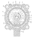
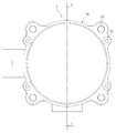
- FIG. 2 is a cross-sectional view taken along line GG in FIG. 1.
- FIG. 2 is a cross-sectional view taken along line HH in FIG. 1.
- FIG. 10 is a cross-sectional view taken along the line II in FIG. 9. It is a schematic diagram for demonstrating the displacement amount detection aspect of a ball screw shaft by a stroke detection sensor. It is a block diagram which shows the control system of an electric actuator.
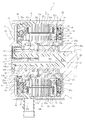
- FIG. 1 is a longitudinal sectional view of an electric actuator provided with a ball screw device according to an embodiment of the present invention
- FIG. 2 is a sectional view taken along line EE in FIG. 1
- FIG. 1 and 2 show a state where the output member of the electric actuator (the ball screw shaft of the ball screw device constituting the electric actuator) is located at the origin.
- the state positioned at the origin is a position where the cover 29 and the spring mounting collar 36 are mechanically contacted by a compression coil spring 48 as an urging member described later.
- FIGS. 1 is a longitudinal sectional view of an electric actuator provided with a ball screw device according to an embodiment of the present invention
- FIG. 2 is a sectional view taken along line EE in FIG. 1
- FIG. 1 and 2 show a state where the output member of the electric actuator (the ball screw shaft of the ball screw device constituting the electric actuator) is located at the origin.
- the state positioned at the origin is a position where the cover 29 and the spring mounting collar 36 are mechanically contacted
- the electric actuator 1 includes a motor unit A that is driven by the supply of electric power, and a motion conversion mechanism unit B that converts the rotational motion of the motor unit A into a linear motion and outputs the linear motion. , An operation unit C for operating an operation target (not shown), and a terminal unit D, which are accommodated and held in the housing 2.
- the housing 2 is composed of a plurality of members coupled in the axial direction in a coaxially arranged state.
- the casing 2 of the present embodiment has an end on one side in the axial direction (the right side in FIG. 1 and FIG. 2), and the other side in the axial direction (the left side in FIG. 1 and FIG. 2).
- a cover 29 that closes the end opening on the other axial side of the casing 20
- a terminal that is disposed between the casing 20 and the cover 29 and constitutes the terminal portion D It consists of a combination with the main body 50.
- the cover 29 and the terminal main body 50 are fixedly attached to the casing 20 by assembly bolts 61 shown in FIGS.
- the motor part A includes a radial gap type motor (in detail, a U-phase, a stator having a stator 23 fixed to the casing 20 and a rotor 24 disposed to face the inner periphery of the stator 23 via a radial gap. 3 phase brushless motor having a V phase and a W phase) 25.
- the stator 23 includes an insulating bobbin 23b attached to the stator core 23a, and a coil 23c wound around the bobbin 23b.
- the rotor 24 includes a rotor core 24a, a permanent magnet 24b attached to the outer periphery of the rotor core 24a, and a hollow shaft-like rotor inner 26 having the rotor core 24a attached to the outer periphery.
- the rotor core 24 a is fitted to the outer peripheral surface 26 b of the rotor inner 26 after setting the side plate 65 on the shoulder portion 26 a on one axial side of the rotor inner 26.
- the side plate 65 attached to the outer side of the other end of the rotor core 24a in the axial direction of the rotor inner 26, and the server attached to the outer side in the axial direction.
- the clip 66 is positioned and fixed.
- an inner raceway surface 27 a of the rolling bearing 27 is formed on the outer periphery of one end of the rotor inner 26 in the axial direction, and the outer ring 27 b of the rolling bearing 27 is fixed to the inner peripheral surface of the casing 20.
- the bearing holder 28 is attached.
- a rolling bearing 30 is mounted between the inner peripheral surface of the other end in the axial direction of the rotor inner 26 and the outer peripheral surface of the cylindrical portion 29 a of the cover 29.
- the motion conversion mechanism B of the present embodiment includes a ball screw device 31 and a speed reducer (planetary gear speed reducer 10).
- the ball screw device 31 constitutes an output member of the electric actuator 1, and can freely rotate on the outer periphery of the ball screw shaft 33 via a ball screw shaft 33 disposed coaxially with the rotor 24 (rotor inner 26) and a plurality of balls 34. And a ball screw nut 32 fitted to each other and a top 35 as a circulation member. A plurality of balls 34 are loaded between a spiral groove 32 a formed on the inner peripheral surface of the ball screw nut 32 and a spiral groove 33 a formed on the outer peripheral surface of the ball screw shaft 33, and two pieces 35. Is incorporated.
- the ball screw shaft 33 is formed in a hollow shape having a hole portion 33b extending in the axial direction (in this embodiment, through-holes opened on both end surfaces in the axial direction) 33b, and the spring mounting collar 36 is accommodated in the hole portion 33b.
- the spring mounting collar 36 is made of, for example, a resin material such as PPS, and has a circular solid portion 36a provided at one end in the axial direction and a flange-shaped spring receiver provided at the other end in the axial direction.
- the part 36b and the cylinder part 36c which connects both parts 36a and 36b are integrally provided.
- the spring mounting collar 36 housed in the hole 33b of the ball screw shaft 33 is connected to the ball screw shaft 33 by fitting a pin 37 so as to penetrate the circular solid portion 36a and the ball screw shaft 33 in the radial direction. Fixed. Both end portions of the pin 37 protrude radially outward from the outer peripheral surface of the ball screw shaft 33, and a guide collar 38 is rotatably fitted on the protruding portion.
- the guide collar 38 is formed of a resin material such as PPS, for example, and is fitted into a guide groove 20b (see also FIG. 5) extending in the axial direction provided on the inner periphery of the small diameter cylindrical portion 20a of the casing 20.
- the planetary gear speed reducer 10 includes a ring gear 40 fixed to the casing 20, a sun gear 41 press-fitted and fixed to the inner peripheral surface of the step portion of the rotor inner 26, and a ring gear 40 and a sun gear 41. And a plurality of (four in this embodiment) planetary gears 42 meshed with both gears 40, 41, and a planetary gear carrier 43 and a planetary gear holder 44 holding the planetary gears 42 rotatably.
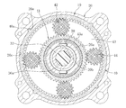
- the outer periphery of the ring gear 40 is provided with notches 40 a projecting radially outward at a plurality of locations (four locations in the illustrated example) spaced apart in the circumferential direction.
- the axial grooves 20e (see also FIG. 5) provided at four locations spaced apart in the circumferential direction of the surface 20c are respectively fitted. Thereby, the ring gear 40 is prevented from rotating with respect to the casing 20.
- the planetary gear carrier 43 is rotatable relative to the rotor inner 26 and, as shown in FIGS. 1 to 3, is a cylinder disposed between the inner peripheral surface of the rotor inner 26 and the outer peripheral surface 32b of the ball screw nut 32. It has the part 43a integrally.
- the outer peripheral surface of the cylindrical portion 43 a faces the inner peripheral surface of the rotor inner 26 (and the inner peripheral surface of the sun gear 41) via a radial gap, and the inner peripheral surface of the cylindrical portion 43 a is press-fitted into the outer peripheral surface 32 b of the ball screw nut 32. It is mated.
- the planetary gear speed reducer 10 having the above configuration, the rotation of the rotor inner 26 of the motor 25 is decelerated and transmitted to the ball screw nut 32. Thereby, since rotational torque can be increased, the small motor 25 can be employ
- a thrust washer 45 is disposed between the end face on one axial side of the ball screw nut 32 and the casing 20, and is attached to the outer periphery of the tip of the cylindrical portion 29 a of the cover 29.
- a thrust needle roller bearing 47 is disposed between the thrust receiving ring 46 and the end face on the other axial side of the ball screw nut 32. The thrust needle roller bearing 47 smoothly supports a thrust load when the ball screw shaft 33 linearly moves (advances) in one axial direction.
- a compression coil spring 48 as an urging member is disposed between the inner peripheral surface 29 b of the cylindrical portion 29 a of the cover 29 and the outer peripheral surface of the ball screw shaft 33. . Ends on one side and the other side in the axial direction of the compression coil spring 48 are in contact with the thrust needle roller bearing 47 and the spring receiving portion 36b of the spring mounting collar 36, respectively.
- the ball screw shaft 33 connected to the spring mounting collar 36 is always urged toward the origin by the spring force of the compression coil spring 48 thus provided. In this way, for example, when the driving power is not properly supplied to the motor unit A (motor 25), the ball screw shaft 33 is automatically returned to the origin, and the operation of the operation target (not shown) is adversely affected. The possibility of exerting can be reduced as much as possible.
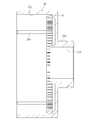
- FIG. 9 is a left side view of FIG. 1, and FIG. 10 is a cross-sectional view taken along the line II in FIG.
- the cover 29 is formed of a metal material excellent in workability (mass productivity) and thermal conductivity, for example, an aluminum alloy, a zinc alloy, or a magnesium alloy.
- a cooling fin for increasing the cooling efficiency of the electric actuator 1 may be provided on the outer surface of the cover 29.
- a bearing mounting surface 63 on which the rolling bearing 30 is mounted and a fitting surface 64 on which the thrust receiving ring 46 is fitted are provided on the outer peripheral surface of the cylindrical portion 29 a of the cover 29. Yes.
- a through hole (not shown) through which the assembly bolt 61 of the electric actuator 1 is inserted and a mounting bolt for attaching the electric actuator 1 to a device to be used are inserted into the cover 29.
- a through hole 62 is provided.
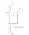
- FIG. 6 is an enlarged longitudinal sectional view of the motor 25 shown in FIG. 1 with the stator 23 and the terminal portion D taken out
- FIG. 7 is a sectional view taken along the line GG in FIG. 1, and FIG. FIG.
- the terminal portion D has a short cylindrical portion constituting a part of the housing 2 and a disk-shaped portion extending radially inward from the other axial end of the short cylindrical portion. And a bus bar 51 and a printed circuit board 52 screwed to the terminal main body 50 (the disk-shaped portion thereof).
- FIGS. 6 is an enlarged longitudinal sectional view of the motor 25 shown in FIG. 1 with the stator 23 and the terminal portion D taken out
- FIG. 7 is a sectional view taken along the line GG in FIG. 1, and FIG. FIG.
- the terminal portion D has a short cylindrical portion constituting a part of the housing 2 and a disk-shaped portion extending radially inward from the other axial end of the short cylindrical portion. And a bus bar 51 and a printed circuit
- the terminal main body 50 (the short cylindrical portion thereof) is provided for attaching the through-hole 50A through which the assembly bolt 61 shown in FIGS. And a through hole 50B through which the bolt is inserted, and is sandwiched between the casing 20 and the cover 29 by the assembly bolt 61 (see FIG. 1).
- the terminal body 50 is formed of a resin material such as PPS, for example.
- the terminal part D (terminal body 50) holds a power feeding circuit for supplying driving power to the motor 25.
- the power feeding circuit connects the coils 23c of the stator 23 to the terminals 51a of the bus bar 51 for each of the U phase, the V phase, and the W phase.
- the terminal 51 b of 51 and the terminal block 50 a of the terminal body 50 are fastened with screws 70.
- the terminal block 50a has a terminal 50b to which a lead wire (not shown) is connected, and the lead wire is an opening 50c (see FIG. 1) provided in the outer peripheral portion (short cylindrical portion) of the terminal body 50. Is pulled out to the outer diameter side of the housing 2 and connected to the controller 81 (see FIG. 12) of the control device 80.
- the electric actuator 1 of this embodiment is equipped with two types of sensors, and these two types of sensors are held in the terminal portion D.
- one of the two types of sensors is a rotation angle detection sensor 53 used for rotation control of the motor 25, and the other is stroke control (amount of displacement in the axial direction) of the ball screw shaft 33.
- This is a stroke detection sensor 55 used for detection.
- a Hall sensor which is a kind of magnetic sensor is used as the rotation angle detection sensor 53 and the stroke detection sensor 55.
- the rotation angle detection sensor 53 is attached to a printed circuit board 52 having a disk shape, and a pulsar ring 54 attached to an end portion on the other side in the axial direction of the rotor inner 26 and a shaft. Oppositely arranged via a directional gap.
- the rotation angle detection sensor 53 determines the timing for supplying current to each of the U phase, V phase, and W phase of the motor 25.
- the stroke detection sensor 55 is attached to a belt-like printed board 56 that extends in the axial direction and has an end on the other side in the axial direction connected to the printed board 52. .
- the printed circuit board 56 and the stroke detection sensor 55 are disposed inside the hole 33b of the ball screw shaft 33, more specifically, on the inner periphery of the cylindrical portion 36c of the spring mounting collar 36 housed in the hole 33b.
- a permanent magnet 57 as a target is attached to the inner periphery of the cylindrical portion 36c of the spring mounting collar 36 so as to face the stroke detection sensor 55 via a radial gap. Permanent magnets 57 are attached at two locations separated in the direction.
- the stroke detection sensor 55 including a Hall sensor detects an axial magnetic field x and a radial magnetic field y formed around the permanent magnet 57, respectively. Based on this, the amount of axial displacement of the ball screw shaft 33 is calculated.
- the signal line of the rotation angle detection sensor 53 and the signal line of the stroke detection sensor 55 are both connected to the housing through the opening 50c (see FIG. 1) of the terminal body 50. 2 is pulled out to the outer diameter side and connected to the control device 80 (see FIG. 12).
- the assembly procedure of the electric actuator 1 having the above configuration will be briefly described.
- the ring gear 40 is assembled in the casing 20.
- the rotor 24 of the motor 25 and the subassembly of the motion conversion mechanism B shown in FIG. 3 are inserted into the casing 20.
- the planetary gear 42 and the ring gear 40 are engaged with each other, the guide collar 38 is fitted into the guide groove 20 b of the casing 20, and the bearing holder 28 is fitted into the inner peripheral surface 20 c of the casing 20.
- the stator 23 is fitted to the inner periphery of the casing 20 in the subassembly of the stator 23 and the terminal body 50 (terminal portion D) of the motor 25 shown in FIG.
- the assembly bolt 61 (see FIG. 9) is used for fastening. Thereby, the electric actuator 1 is completed.
- the ball screw shaft 33 is formed in a hollow shape, A stroke detection sensor 55 for detecting the amount of axial displacement of the ball screw shaft 33 is disposed around the circumference. According to such a configuration, the axial displacement amount of the ball screw shaft 33 can be directly detected, and when the displacement amount of the ball screw shaft 33 is detected, the ball screw shaft 33 and the ball screw nut 32 are included.
- the ball screw device 31 is not affected by play, rigidity, operation accuracy, and the like. For this reason, the amount of displacement of the ball screw shaft 33 in the axial direction can be accurately detected.
- the motion conversion mechanism B is provided with the planetary gear speed reducer 10 that decelerates the rotation of the motor part A and transmits it to the ball screw nut 32.
- the accuracy does not affect the detection of the displacement amount of the ball screw shaft 33 in the axial direction. Therefore, it is possible to realize the ball screw device 31 that is excellent in the operation accuracy of the ball screw shaft 33 and has high reliability, and thus the electric actuator 1.
- the stroke detection sensor 55 is arranged on the inner periphery of the ball screw shaft 33 formed in a hollow shape, the sensor for sensor arrangement is used as in the case where this type of sensor is arranged outside the ball screw shaft 33. It is no longer necessary to secure a dedicated space. Therefore, the electric actuator 1 can be reduced in weight and size, and the mountability with respect to the equipment used can be improved.
- the rotor inner 26 is rotatably supported at one end in the axial direction by a rolling bearing 27 disposed in the vicinity of one end in the axial direction of the rotor core 24a, and is supported at the other end in the axial direction of the rotor core 24a.
- An end portion on the other side in the axial direction is rotatably supported by the rolling bearings 30 arranged close to each other.
- the rotor inner 26 can be made compact in the axial direction.
- the structure in which the rolling bearing 27 is disposed inside the axial width of the ball screw nut 32 is combined to shorten the axial dimension L (see FIG. 1) of the housing 2 of the electric actuator 1. can do.
- the rolling bearings 27 and 30 that support the rotor inner 26 may support a radial load about the weight of the rotor 24.
- the rotor inner 26 integrally including the inner raceway surface 27a of the rolling bearing 27 does not need to be formed of a high-strength material.
- the rotor inner 26 may be formed of an inexpensive mild steel material in which heat treatment such as quenching and tempering is omitted. Necessary strength can be ensured.
- the thrust needle roller bearing 47 is disposed within the axial range between the rolling bearings 27 and 30 that support the rotor inner 26, it is advantageous for moment load, and a small-sized one is used as the bearing. it can.
- a small-sized one is used as the bearing. it can.
- the thrust needle roller bearing 47 when the thrust needle roller bearing 47 is arranged near the center in the axial direction between the rolling bearings 27 and 30 that support the rotor inner 26, it is extremely advantageous with respect to the moment load.
- the downsizing of the needle roller bearing 47 can be further promoted. As a result, it is possible to employ extremely small ones as the thrust needle roller bearing 47, the thrust receiving ring 46 and the like, and through this, the electric actuator 1 can be made compact as a whole.
- the planetary gear carrier 43 and the ball screw nut 32 are formed by using the cylindrical portion 43a of the planetary gear carrier 43 as an output portion of the planetary gear speed reducer 10 and press fitting the cylindrical portion 43a to the outer peripheral surface 32b of the ball screw nut 32.
- the size reduction of the motor part A (motor 25) by providing the planetary gear speed reducer 10 in the motion conversion mechanism part B, and the radial direction of the rotor inner 26, the cylindrical part 43a of the planetary gear carrier 43 and the ball screw nut 32 are achieved.
- the radial dimension M (see FIG. 1) of the housing 2 of the electric actuator 1 can also be reduced. Thereby, the electric actuator 1 can be made more compact, and the mountability with respect to the equipment used is further improved.
- the sun gear 41 of the planetary gear speed reducer 10 is press-fitted and fitted to the inner peripheral surface of the rotor inner 26, so that the rotor inner 26 and the sun gear 41 are connected so that torque can be transmitted.
- Good connection workability Even if such a connection structure is adopted, the sun gear 41 only needs to be able to rotate integrally with the rotor inner 26 before deceleration, and therefore the torque transmission performance required between the two can be sufficiently ensured.
- the rotor inner 26 and the sun gear 41 are connected at a position directly below the rolling bearing 27 that supports the rotor inner 26, the rotational accuracy of the sun gear 41 is also good.
- the rotor inner 26 and the ball screw nut 32 have a separate structure, for example, even when the ball screw device 31 having different specifications is used, the rotor inner 26 (and thus the motor part A) can be shared. As a result, the versatility is improved, and it becomes easy to realize a series of electric actuators 1 with a wide variety of deployments in which parts are shared.
- the lead wire of the power feeding circuit and the signal line of the sensor are connected to the housing 2 (electric actuator 1) through the sandwich structure and the opening 50c provided in the outer peripheral portion (short cylindrical portion) of the terminal body 50.
- the operation mode of the electric actuator 1 of the present embodiment will be briefly described with reference to FIGS. 1 and 12. Although illustration is omitted, for example, when an operation amount is input to an upper ECU of the vehicle, the ECU calculates a required position command value based on the operation amount. As shown in FIG. 12, the position command value is sent to the controller 81 of the control device 80, and the controller 81 calculates a motor rotation angle control signal necessary for the position command value, and sends this control signal to the motor 25.
- the rotor 24 (rotor inner 26) rotates based on the control signal sent from the controller 81, and this rotational motion is transmitted to the motion converting mechanism B.
- the sun gear 41 of the planetary gear speed reducer 10 connected to the rotor inner 26 rotates, and accordingly, the planetary gear 42 revolves and the planetary gear carrier 43 rotates.
- the rotational motion of the rotor inner 26 is transmitted to the ball screw nut 32 connected to the planetary gear carrier 43.
- the revolution speed of the planetary gear 42 reduces the rotational speed of the rotor inner 26, so that the rotational torque transmitted to the ball screw nut 32 increases.
- the ball screw shaft 33 moves linearly (advances) in one axial direction while being prevented from rotating. At this time, the ball screw shaft 33 moves forward to a position based on a control signal of the controller 81, and an actuator head 39 attached to one end of the ball screw shaft 33 in the axial direction operates an operation target (not shown) in the axial direction. .
- the axial position (the amount of axial displacement) of the ball screw shaft 33 is detected by the stroke detection sensor 55 as shown in FIG. 12, and the detected value is sent to the comparison unit 82 of the control device 80. Then, the comparison unit 82 calculates the difference between the detection value detected by the stroke detection sensor 55 and the position command value, and the controller 81 is based on the calculated value and the signal sent from the rotation angle detection sensor 53. A control signal is sent to the motor 25. In this way, the position of the actuator head 39 is feedback controlled. For this reason, when the electric actuator 1 of this embodiment is applied to, for example, shift-by-wire, the shift position can be reliably controlled. Electric power for driving the motor unit A (motor 25), the sensors 53, 55, and the like is supplied from an external power source (not shown) such as a battery provided on the vehicle side to the motor 25, etc. via the control device 80. Supplied.
- the ball screw device 31 according to the embodiment of the present invention and the electric actuator 1 including the ball screw device 31 have been described, but the embodiment of the present invention is not limited thereto.
- the ball screw shaft 33 is formed in a hollow shape by providing holes 33b (through holes in the axial direction) that are opened on both end surfaces of the ball screw shaft 33 in the axial direction.
- the stroke detection sensor 55 is disposed on the inner periphery of the ball screw shaft 33.
- the ball screw shaft 33 is provided with a hole 33b extending in the axial direction and opened only on the other end surface in the axial direction.
- the stroke detection sensor 55 may be arranged.
- the compression coil spring 48 is provided as a biasing member that constantly biases the ball screw shaft 33 toward the origin, but the compression coil spring 48 requires a function of biasing. It may be provided according to the intended use, and may be omitted if not required.
- the planetary gear speed reducer 10 is adopted as the speed reducer constituting the motion conversion mechanism B, but a speed reducer having another mechanism may be adopted. Further, the present invention can be applied not only to the electric actuator 1 provided with a reduction gear but also to the electric actuator 1 not provided with a reduction gear. Although illustration is omitted, when the reduction gear is omitted, the ball screw nut 32 and the rotor inner 26 may be connected so as to be able to transmit torque directly.
- the ball screw device 31 according to the present invention can be applied not only to the electric actuator 1 described above but also to other electric devices.
Abstract
A ball screw device 31 which is equipped with a ball screw shaft 33 and a ball screw nut 32 for rotatably engaging the outer periphery of the ball screw shaft 33 via a plurality of balls 34, and causes the ball screw shaft 33 to move linearly in the axial direction in response to the rotation of the ball screw nut 32, wherein: the ball screw shaft 33 is formed so as to be hollow and to have a hole 33b therein extending in the axial direction; and a stroke detection sensor 55 for detecting the amount of displacement of the ball screw shaft 33 in the axial direction is provided inside the hole 33b.
Description
本発明は、ボールねじ装置およびこれを備える電動アクチュエータに関する。
The present invention relates to a ball screw device and an electric actuator including the same.
回転運動を直線運動に変換して出力する運動変換装置の一つに、ボールねじ軸と、複数のボールを介してボールねじ軸の外周に回転自在に嵌合されたボールねじナットとを備えたボールねじ装置がある。また、この種のボールねじ装置を運動変換機構に採用したものとして、例えば、自動車の自動変速機、ブレーキおよびステアリング等の操作をモータ(電動モータ)の力を利用して行う電動アクチュエータがある(特許文献1)。特許文献1の電動アクチュエータは、モータの回転運動を受けてボールねじナットが回転(ボールねじ軸の軸線回りに回転)するのに伴って、ボールねじ軸が軸方向に進退移動するように構成されている。
One of the motion conversion devices that convert rotational motion into linear motion and output is provided with a ball screw shaft and a ball screw nut that is rotatably fitted to the outer periphery of the ball screw shaft via a plurality of balls. There is a ball screw device. Further, as an example of adopting this type of ball screw device for a motion conversion mechanism, there is an electric actuator that performs operations of an automatic transmission, a brake, a steering, and the like of an automobile by using the power of a motor (electric motor) ( Patent Document 1). The electric actuator of Patent Document 1 is configured such that the ball screw shaft moves forward and backward in the axial direction as the ball screw nut rotates (rotates around the axis of the ball screw shaft) in response to the rotational motion of the motor. ing.
特許文献1の電動アクチュエータのように、運動変換機構にボールねじ装置を採用し、かつボールねじ軸が当該アクチュエータの出力部材を構成するものにおいては、ボールねじ軸の軸方向の進退移動量(軸方向の変位量)に応じた出力(荷重)が操作対象に付与されることから、ボールねじ軸の軸方向の変位量を高精度に管理・制御する必要がある。このため、この種の電動アクチュエータにおいては、通常、ボールねじ軸の軸方向の変位量を検出するためのセンサが設けられる。特許文献1の電動アクチュエータにおいては、回転角センサと、モータロータとしても機能するボールねじナットに設けた磁石とを軸方向のすきまを介して対向配置することにより、ボールねじナットの回転に伴う磁石の磁束変化を検出し、その検出値に基づいてボールねじ軸の軸方向の変位量を間接的に導出することができるようにしている。
In the case where a ball screw device is employed in the motion conversion mechanism and the ball screw shaft constitutes an output member of the actuator as in the electric actuator of Patent Document 1, the amount of axial movement of the ball screw shaft (axis Since an output (load) corresponding to the displacement amount in the direction) is given to the operation target, it is necessary to manage and control the displacement amount in the axial direction of the ball screw shaft with high accuracy. For this reason, this type of electric actuator is usually provided with a sensor for detecting the amount of axial displacement of the ball screw shaft. In the electric actuator of Patent Document 1, a rotation angle sensor and a magnet provided on a ball screw nut that also functions as a motor rotor are arranged to face each other via an axial clearance, so that the magnet of the ball screw nut is rotated. A change in magnetic flux is detected, and the amount of axial displacement of the ball screw shaft can be indirectly derived based on the detected value.
しかしながら、特許文献1のように、ボールねじ軸の軸方向の変位量を間接的に導出するようにした場合、ボールねじ軸の変位量検出に際しては、ボールねじ装置のガタ、剛性、動作精度等の影響を受けるため、ボールねじ軸の変位量を必ずしも正確に検出できるとは限らない。このため、ボールねじ軸の動作精度に優れ、信頼性に富むボールねじ装置、ひいては電動アクチュエータを実現できない可能性がある。特に、例えば大荷重を必要とする操作対象の制御用途に電動アクチュエータを適用すべく、モータ部とボールねじ装置との間に減速機を設けるような場合、ボールねじ軸の変位量検出に際しては減速機の動作精度等にも影響を受けることになるため、ボールねじ軸の変位量検出を正確に行うことができない可能性が一層高まる。
However, when the displacement amount of the ball screw shaft in the axial direction is derived indirectly as in Patent Document 1, when detecting the displacement amount of the ball screw shaft, the backlash, rigidity, operation accuracy, etc. of the ball screw device are detected. Therefore, the amount of displacement of the ball screw shaft cannot always be accurately detected. For this reason, there is a possibility that a ball screw device excellent in the operation accuracy of the ball screw shaft and having high reliability, and thus an electric actuator cannot be realized. In particular, when a reduction gear is provided between the motor unit and the ball screw device in order to apply an electric actuator to the control application of an operation target that requires a large load, for example, the deceleration is detected when detecting the displacement amount of the ball screw shaft. Since this is also affected by the operation accuracy of the machine, the possibility that the displacement amount of the ball screw shaft cannot be accurately detected is further increased.
その一方、この種の電動アクチュエータを自動車等の車両に用いる場合には、使用機器に対する良好な搭載性を確保するためにも、できるだけ軽量・コンパクトであることが求められる。
On the other hand, when this type of electric actuator is used in a vehicle such as an automobile, it is required to be as light and compact as possible in order to ensure good mountability on the equipment used.
以上の実情に鑑み、本発明の課題は、軽量・コンパクトで、かつボールねじ軸の軸方向の変位量を正確に検出することができるボールねじ装置を実現することにある。また、本発明の他の課題は、軽量・コンパクトで使用機器に対する搭載性に優れ、かつ出力部材の動作精度に優れた信頼性に富む電動アクチュエータを実現することにある。
In view of the above circumstances, an object of the present invention is to realize a ball screw device that is lightweight and compact and that can accurately detect the amount of axial displacement of a ball screw shaft. Another object of the present invention is to realize a highly reliable electric actuator that is light and compact, excellent in mountability to a device used, and excellent in operation accuracy of an output member.
上記の課題を解決するために創案された本発明は、ボールねじ軸と、複数のボールを介してボールねじ軸の外周に回転自在に嵌合されたボールねじナットとを備え、ボールねじナットが回転するのに伴ってボールねじ軸が軸方向に進退移動するボールねじ装置において、ボールねじ軸が軸方向に延びた孔部を有する中空状に形成され、上記孔部に、ボールねじ軸の軸方向の変位量を検出するためのストローク検出用センサが配置されていることを特徴とする。
In order to solve the above problems, the present invention comprises a ball screw shaft and a ball screw nut that is rotatably fitted to the outer periphery of the ball screw shaft via a plurality of balls. In the ball screw device in which the ball screw shaft moves forward and backward in the axial direction as it rotates, the ball screw shaft is formed in a hollow shape having a hole extending in the axial direction, and the shaft of the ball screw shaft is formed in the hole. A stroke detection sensor for detecting the amount of displacement in the direction is arranged.
このような構成によれば、ボールねじ軸の軸方向の変位量を直接検出することができ、ボールねじ軸の変位量検出に際して、ボールねじ装置のガタ、剛性、動作精度等の影響を受けることがなくなるため、ボールねじ軸の変位量を正確に検出することができる。このような作用効果は、ボールねじナットに回転力を付与するエンジンやモータ等の原動機とボールねじナットとの間に、原動機の回転を減速してボールねじナットに伝達する減速機を追加的に設けた場合にも同様に享受することができる。このため、ボールねじ軸の動作精度に優れ、信頼性に富むボールねじ装置を実現することができる。また、ストローク検出用センサは、中空状に形成されたボールねじ軸の内周に配置されるため、この種のセンサをボールねじ軸の外部に配置する場合のように、センサ配置用の専用スペースを別途確保する必要がなくなる。そのため、ストローク検出用センサを含んで構成されるボールねじ装置を軽量・コンパクト化することができる。
According to such a configuration, the amount of axial displacement of the ball screw shaft can be directly detected, and when detecting the amount of displacement of the ball screw shaft, it is affected by the play, rigidity, operational accuracy, etc. of the ball screw device. Therefore, the displacement amount of the ball screw shaft can be accurately detected. Such an operational effect is additionally provided between a prime mover such as an engine or a motor that applies rotational force to the ball screw nut and the ball screw nut, and a speed reducer that decelerates the rotation of the prime mover and transmits it to the ball screw nut. In the case where it is provided, it can be enjoyed similarly. For this reason, it is possible to realize a ball screw device that is excellent in the operation accuracy of the ball screw shaft and is rich in reliability. In addition, since the sensor for detecting the stroke is arranged on the inner periphery of the ball screw shaft formed in a hollow shape, a dedicated space for sensor arrangement is provided as in the case where this type of sensor is arranged outside the ball screw shaft. Need not be separately secured. Therefore, the ball screw device including the stroke detection sensor can be reduced in weight and size.
ストローク検出用センサは、径方向隙間を介して対向配置された永久磁石の周囲に形成される軸方向および径方向の磁界を検出し、これに基づいてボールねじ軸の軸方向の変位量を算出するホールセンサとすることができる。
The stroke detection sensor detects the axial and radial magnetic fields formed around the permanent magnets opposed to each other via a radial gap, and calculates the axial displacement of the ball screw shaft based on this. It can be set as a hall sensor.
本発明に係るボールねじ装置は、上述したような特長を有することから、電力の供給を受けて駆動されるモータ部と、モータ部の回転運動を直線運動に変換する運動変換機構部とを備え、運動変換機構部に上記のボールねじ装置を採用し、かつ、ボールねじ軸の中心軸とモータ部の回転中心とを一致させた電動アクチュエータは、軽量・コンパクトで使用機器に対する搭載性に優れ、かつ出力部材の動作精度に優れた信頼性に富むものとなる。
Since the ball screw device according to the present invention has the above-described features, the ball screw device includes a motor unit that is driven by power supply and a motion conversion mechanism unit that converts the rotational motion of the motor unit into linear motion. The electric actuator that adopts the above-mentioned ball screw device for the motion conversion mechanism section and matches the center axis of the ball screw shaft and the rotation center of the motor section is lightweight and compact and has excellent mountability to the equipment used. In addition, the operation accuracy of the output member is excellent and the reliability is high.
運動変換機構部には、モータ部の回転を減速してボールねじナットに伝達する減速機をさらに設けることができる。この場合、小型のモータを採用することができるので、電動アクチュエータを一層軽量・コンパクト化することができる。減速機としては、遊星歯車減速機を採用することができる。遊星歯車減速機であれば、例えば、歯車緒元を変更したり、遊星ギヤの設置段数を変更したりすることで減速比を容易に調整することができ、しかも遊星ギヤを多段に設置しても減速機の大型化を回避することができる、という利点がある。
The motion conversion mechanism can be further provided with a speed reducer that decelerates the rotation of the motor and transmits it to the ball screw nut. In this case, since a small motor can be adopted, the electric actuator can be further reduced in weight and size. A planetary gear speed reducer can be adopted as the speed reducer. If it is a planetary gear reducer, for example, the reduction ratio can be easily adjusted by changing the gear specifications or changing the number of installation stages of the planetary gear, and the planetary gears are installed in multiple stages. However, there is an advantage that an enlargement of the reduction gear can be avoided.
電動アクチュエータは、ボールねじ軸を常時原点側に付勢する付勢部材を有するものとしても良い。このようにすれば、例えば、モータ部に適切に駆動電力が供給されないような場合には、ボールねじ軸を自動的に原点復帰させ、操作対象(使用機器)の作動に悪影響を及ぼす可能性を可及的に低減することができる。
The electric actuator may have a biasing member that constantly biases the ball screw shaft toward the origin. In this way, for example, when the driving power is not properly supplied to the motor unit, the ball screw shaft is automatically returned to the origin, and there is a possibility that the operation of the operation target (use device) may be adversely affected. It can be reduced as much as possible.
上記構成の電動アクチュエータは、軸方向に結合された複数部材からなり、モータ部および運動変換機構部を収容した筐体と、モータ部に電力(駆動電力)を供給するための給電回路およびストローク検出用センサを保持したターミナル部とを有するものとすることができる。この場合、ターミナル部は、筐体の構成部材により軸方向両側から挟持することができる。これにより、電動アクチュエータの組立性を向上することができる。
The electric actuator having the above-described configuration is composed of a plurality of members coupled in the axial direction, a housing that houses the motor unit and the motion conversion mechanism unit, a power feeding circuit for supplying power (driving power) to the motor unit, and stroke detection. And a terminal portion holding a sensor for use. In this case, the terminal portion can be held from both sides in the axial direction by the constituent members of the casing. Thereby, the assembly property of the electric actuator can be improved.
ターミナル部は、その外周部に、給電回路に接続されるリード線、およびストローク検出用センサに接続される信号線を筐体の外径側に引き出すための開口部を有するものとすることができる。このようにすれば、例えば、複数の電動アクチュエータを直列に配置し、かつ各ボールねじ軸を個別に直線運動させることができる電動アクチュエータを容易に実現することができる。このような電動アクチュエータは、操作対象が2以上ある使用機器、例えば、自動変速機の一種であるDCT(Dual Clutch Transmission)に搭載することができ、自動変速機全体の簡素化および軽量・コンパクト化に貢献できる。
The terminal portion may have an opening for pulling out a lead wire connected to the power feeding circuit and a signal wire connected to the stroke detection sensor to the outer diameter side of the housing on the outer peripheral portion thereof. . In this way, for example, it is possible to easily realize an electric actuator in which a plurality of electric actuators are arranged in series and each ball screw shaft can be individually linearly moved. Such an electric actuator can be mounted on a device that has two or more objects to be operated, such as DCT (Dual Clutch Transmission), which is a kind of automatic transmission, and the entire automatic transmission is simplified and lightweight and compact. Can contribute.
以上より、本発明によれば、軽量・コンパクトで、かつ、ボールねじ軸の軸方向の変位量を正確に検出することができるボールねじ装置を実現することができる。また、本発明に係るボールねじ装置を電動アクチュエータの運動変換機構部に適用すれば、軽量・コンパクトで使用機器に対する搭載性に優れ、かつ、出力部材の動作精度に優れた信頼性に富む電動アクチュエータを実現することができる。
As described above, according to the present invention, it is possible to realize a ball screw device that is lightweight and compact and that can accurately detect the amount of axial displacement of the ball screw shaft. In addition, if the ball screw device according to the present invention is applied to the motion conversion mechanism of an electric actuator, the electric actuator is light and compact, excellent in mountability to equipment used, and excellent in operation accuracy of the output member and rich in reliability. Can be realized.
以下、本発明の実施の形態を図面に基づいて説明する。
Hereinafter, embodiments of the present invention will be described with reference to the drawings.
図1に、本発明の一実施形態に係るボールねじ装置を備えた電動アクチュエータの縦断面図を示し、図2に、図1のE-E線矢視断面図を示し、図3に、モータのロータと運動変換機構部とを取り出して拡大した縦断面図を示す。なお、図1および図2は、電動アクチュエータの出力部材(を構成するボールねじ装置のボールねじ軸)が原点に位置した状態を示している。原点に位置した状態とは、後述する付勢部材としての圧縮コイルばね48によりカバー29とばね取付カラー36とが機械的に当接する位置のことである。図1および図2に示すように、電動アクチュエータ1は、電力の供給を受けて駆動されるモータ部Aと、モータ部Aの回転運動を直線運動に変換して出力する運動変換機構部Bと、図示外の操作対象を操作する操作部Cと、ターミナル部Dとを備え、これらは筐体2に収容・保持されている。
FIG. 1 is a longitudinal sectional view of an electric actuator provided with a ball screw device according to an embodiment of the present invention, FIG. 2 is a sectional view taken along line EE in FIG. 1, and FIG. The longitudinal cross-sectional view which took out and expanded the rotor and the motion conversion mechanism part of this is shown. 1 and 2 show a state where the output member of the electric actuator (the ball screw shaft of the ball screw device constituting the electric actuator) is located at the origin. The state positioned at the origin is a position where the cover 29 and the spring mounting collar 36 are mechanically contacted by a compression coil spring 48 as an urging member described later. As shown in FIGS. 1 and 2, the electric actuator 1 includes a motor unit A that is driven by the supply of electric power, and a motion conversion mechanism unit B that converts the rotational motion of the motor unit A into a linear motion and outputs the linear motion. , An operation unit C for operating an operation target (not shown), and a terminal unit D, which are accommodated and held in the housing 2.
筐体2は、同軸配置された状態で軸方向に結合された複数部材からなる。本実施形態の筐体2は、軸方向一方側(図1および図2においては紙面右側。以下同様。)の端部および軸方向他方側(図1および図2においては紙面左側。以下同様。)の端部が開口した筒状のケーシング20と、ケーシング20の軸方向他方側の端部開口を閉塞するカバー29と、ケーシング20とカバー29の間に配置され、ターミナル部Dを構成するターミナル本体50との結合体からなる。カバー29およびターミナル本体50は、図9,10に示す組立用ボルト61によりケーシング20に対して取り付け固定されている。
The housing 2 is composed of a plurality of members coupled in the axial direction in a coaxially arranged state. The casing 2 of the present embodiment has an end on one side in the axial direction (the right side in FIG. 1 and FIG. 2), and the other side in the axial direction (the left side in FIG. 1 and FIG. 2). ) Of the cylindrical casing 20 having an open end, a cover 29 that closes the end opening on the other axial side of the casing 20, and a terminal that is disposed between the casing 20 and the cover 29 and constitutes the terminal portion D It consists of a combination with the main body 50. The cover 29 and the terminal main body 50 are fixedly attached to the casing 20 by assembly bolts 61 shown in FIGS.
モータ部Aは、ケーシング20に固定されたステータ23と、径方向隙間を介してステータ23の内周に対向配置されたロータ24とを備えたラジアルギャップ型のモータ(詳細には、U相、V相およびW相を有する三相ブラシレスモータ)25で構成されている。ステータ23は、ステータコア23aに装着された絶縁用のボビン23bと、ボビン23bに巻き回されたコイル23cとを備える。ロータ24は、ロータコア24aと、ロータコア24aの外周に取り付けられた永久磁石24bと、ロータコア24aを外周に装着した中空軸状のロータインナ26とを備える。
The motor part A includes a radial gap type motor (in detail, a U-phase, a stator having a stator 23 fixed to the casing 20 and a rotor 24 disposed to face the inner periphery of the stator 23 via a radial gap. 3 phase brushless motor having a V phase and a W phase) 25. The stator 23 includes an insulating bobbin 23b attached to the stator core 23a, and a coil 23c wound around the bobbin 23b. The rotor 24 includes a rotor core 24a, a permanent magnet 24b attached to the outer periphery of the rotor core 24a, and a hollow shaft-like rotor inner 26 having the rotor core 24a attached to the outer periphery.
図3に示すように、ロータコア24aは、ロータインナ26の軸方向一方側の肩部26aにサイドプレート65をセットした後、ロータインナ26の外周面26bに嵌合される。永久磁石24bは、ロータコア24aの外周に嵌合された後、ロータインナ26のうち、ロータコア24aの軸方向他方側の端部外側に取り付けられたサイドプレート65、およびその軸方向外側に取り付けられたサークリップ66により位置決め固定されている。
As shown in FIG. 3, the rotor core 24 a is fitted to the outer peripheral surface 26 b of the rotor inner 26 after setting the side plate 65 on the shoulder portion 26 a on one axial side of the rotor inner 26. After the permanent magnet 24b is fitted to the outer periphery of the rotor core 24a, the side plate 65 attached to the outer side of the other end of the rotor core 24a in the axial direction of the rotor inner 26, and the server attached to the outer side in the axial direction. The clip 66 is positioned and fixed.
図1~図3に示すように、ロータインナ26の軸方向一方側の端部外周には転がり軸受27の内側軌道面27aが形成され、転がり軸受27の外輪27bはケーシング20の内周面に固定された軸受ホルダ28に装着されている。また、ロータインナ26の軸方向他方側の端部内周面と、カバー29の円筒部29aの外周面との間に転がり軸受30が装着されている。このような構成により、ロータインナ26は、転がり軸受27,30を介して筐体2に対して回転自在に支持されている。
As shown in FIGS. 1 to 3, an inner raceway surface 27 a of the rolling bearing 27 is formed on the outer periphery of one end of the rotor inner 26 in the axial direction, and the outer ring 27 b of the rolling bearing 27 is fixed to the inner peripheral surface of the casing 20. The bearing holder 28 is attached. Further, a rolling bearing 30 is mounted between the inner peripheral surface of the other end in the axial direction of the rotor inner 26 and the outer peripheral surface of the cylindrical portion 29 a of the cover 29. With such a configuration, the rotor inner 26 is rotatably supported with respect to the housing 2 via the rolling bearings 27 and 30.
図1~図3に示すように、本実施形態の運動変換機構部Bは、ボールねじ装置31と、減速機(遊星歯車減速機10)とを備える。
As shown in FIGS. 1 to 3, the motion conversion mechanism B of the present embodiment includes a ball screw device 31 and a speed reducer (planetary gear speed reducer 10).
ボールねじ装置31は、電動アクチュエータ1の出力部材を構成し、ロータ24(ロータインナ26)と同軸に配置されたボールねじ軸33と、複数のボール34を介してボールねじ軸33の外周に回転自在に嵌合されたボールねじナット32と、循環部材としてのこま35とを備える。ボールねじナット32の内周面に形成された螺旋状溝32aと、ボールねじ軸33の外周面に形成された螺旋状溝33aとの間に複数のボール34が装填され、2個のこま35が組み込まれている。このような構成により、ボールねじ軸33が軸方向に進退移動(直線運動)する際には、両螺旋状溝32a,33aの間で2列のボール34が循環する。ボールねじ軸33の軸方向一方側の端部には、操作部Cとしてのアクチュエータヘッド39が着脱可能に装着されている。
The ball screw device 31 constitutes an output member of the electric actuator 1, and can freely rotate on the outer periphery of the ball screw shaft 33 via a ball screw shaft 33 disposed coaxially with the rotor 24 (rotor inner 26) and a plurality of balls 34. And a ball screw nut 32 fitted to each other and a top 35 as a circulation member. A plurality of balls 34 are loaded between a spiral groove 32 a formed on the inner peripheral surface of the ball screw nut 32 and a spiral groove 33 a formed on the outer peripheral surface of the ball screw shaft 33, and two pieces 35. Is incorporated. With such a configuration, when the ball screw shaft 33 moves back and forth in the axial direction (linear motion), the two rows of balls 34 circulate between the spiral grooves 32a and 33a. An actuator head 39 as an operation portion C is detachably attached to an end portion on one axial side of the ball screw shaft 33.
ボールねじ軸33は、軸方向に延びた孔部(本実施形態では、軸方向両側の端面に開口した貫通穴)33bを有する中空状に形成され、孔部33bにばね取付カラー36が収容されている。ばね取付カラー36は、例えばPPS等の樹脂材料で形成され、軸方向一方側の端部に設けられた円形中実部36aと、軸方向他方側の端部に設けられたフランジ状のばね受け部36bと、両部36a,36bを接続する筒部36cとを一体に有する。
The ball screw shaft 33 is formed in a hollow shape having a hole portion 33b extending in the axial direction (in this embodiment, through-holes opened on both end surfaces in the axial direction) 33b, and the spring mounting collar 36 is accommodated in the hole portion 33b. ing. The spring mounting collar 36 is made of, for example, a resin material such as PPS, and has a circular solid portion 36a provided at one end in the axial direction and a flange-shaped spring receiver provided at the other end in the axial direction. The part 36b and the cylinder part 36c which connects both parts 36a and 36b are integrally provided.
ボールねじ軸33の孔部33bに収容されたばね取付カラー36は、その円形中実部36aとボールねじ軸33とを径方向に貫通するようにピン37を嵌め込むことによってボールねじ軸33と連結固定される。ピン37の両端部は、ボールねじ軸33の外周面から径方向外側に突出しており、この突出部分にガイドカラー38が回転自在に外嵌されている。ガイドカラー38は、例えばPPS等の樹脂材料で形成され、ケーシング20の小径円筒部20aの内周に設けられた軸方向に延びる案内溝20b(図5も併せて参照)に嵌め込まれている。このような構成により、モータ25の回転に伴ってボールねじナット32がボールねじ軸33の軸線回りに回転すると、ボールねじ軸33は回り止めされた状態で軸方向に直線運動する。
The spring mounting collar 36 housed in the hole 33b of the ball screw shaft 33 is connected to the ball screw shaft 33 by fitting a pin 37 so as to penetrate the circular solid portion 36a and the ball screw shaft 33 in the radial direction. Fixed. Both end portions of the pin 37 protrude radially outward from the outer peripheral surface of the ball screw shaft 33, and a guide collar 38 is rotatably fitted on the protruding portion. The guide collar 38 is formed of a resin material such as PPS, for example, and is fitted into a guide groove 20b (see also FIG. 5) extending in the axial direction provided on the inner periphery of the small diameter cylindrical portion 20a of the casing 20. With such a configuration, when the ball screw nut 32 rotates around the axis of the ball screw shaft 33 as the motor 25 rotates, the ball screw shaft 33 linearly moves in the axial direction while being prevented from rotating.
遊星歯車減速機10は、図1~図4に示すように、ケーシング20に固定されたリングギヤ40と、ロータインナ26の段部内周面に圧入固定されたサンギヤ41と、リングギヤ40とサンギヤ41の間に配置され、両ギヤ40,41に噛合った複数(本実施形態では4つ)の遊星ギヤ42と、遊星ギヤ42を回転自在に保持した遊星ギヤキャリア43および遊星ギヤホルダ44と、を備える。
As shown in FIGS. 1 to 4, the planetary gear speed reducer 10 includes a ring gear 40 fixed to the casing 20, a sun gear 41 press-fitted and fixed to the inner peripheral surface of the step portion of the rotor inner 26, and a ring gear 40 and a sun gear 41. And a plurality of (four in this embodiment) planetary gears 42 meshed with both gears 40, 41, and a planetary gear carrier 43 and a planetary gear holder 44 holding the planetary gears 42 rotatably.
図4に示すように、リングギヤ40の外周には径方向外側に突出したノッチ40aが周方向に離間した複数箇所(図示例では4箇所)に設けられ、各ノッチ40aは、ケーシング20の内周面20cの周方向に離間した4箇所に設けられた軸方向溝20e(図5を併せて参照)にそれぞれ嵌合されている。これにより、リングギヤ40は、ケーシング20に対して回り止めされている。
As shown in FIG. 4, the outer periphery of the ring gear 40 is provided with notches 40 a projecting radially outward at a plurality of locations (four locations in the illustrated example) spaced apart in the circumferential direction. The axial grooves 20e (see also FIG. 5) provided at four locations spaced apart in the circumferential direction of the surface 20c are respectively fitted. Thereby, the ring gear 40 is prevented from rotating with respect to the casing 20.
遊星ギヤキャリア43は、ロータインナ26に対して相対回転可能であり、図1~図3に示すように、ロータインナ26の内周面とボールねじナット32の外周面32bとの間に配置された円筒部43aを一体に有する。円筒部43aの外周面はロータインナ26の内周面(およびサンギヤ41の内周面)と径方向隙間を介して対向し、円筒部43aの内周面はボールねじナット32の外周面32bに圧入嵌合されている。以上の構成を有する遊星歯車減速機10により、モータ25のロータインナ26の回転が減速された上でボールねじナット32に伝達される。これにより、回転トルクを増加することができるので、小型のモータ25を採用することができ、電動アクチュエータ1を全体として軽量・コンパクト化することができる。
The planetary gear carrier 43 is rotatable relative to the rotor inner 26 and, as shown in FIGS. 1 to 3, is a cylinder disposed between the inner peripheral surface of the rotor inner 26 and the outer peripheral surface 32b of the ball screw nut 32. It has the part 43a integrally. The outer peripheral surface of the cylindrical portion 43 a faces the inner peripheral surface of the rotor inner 26 (and the inner peripheral surface of the sun gear 41) via a radial gap, and the inner peripheral surface of the cylindrical portion 43 a is press-fitted into the outer peripheral surface 32 b of the ball screw nut 32. It is mated. By the planetary gear speed reducer 10 having the above configuration, the rotation of the rotor inner 26 of the motor 25 is decelerated and transmitted to the ball screw nut 32. Thereby, since rotational torque can be increased, the small motor 25 can be employ | adopted and the electric actuator 1 can be reduced in weight and compact as a whole.
図1~図3に示すように、ボールねじナット32の軸方向一方側の端面とケーシング20との間にスラストワッシャ45が配設され、カバー29の円筒部29aの先端部外周に取り付けられたスラスト受けリング46とボールねじナット32の軸方向他方側の端面との間にスラスト針状ころ軸受47が配設されている。このスラスト針状ころ軸受47により、ボールねじ軸33が軸方向一方側に直線運動(前進)する際のスラスト荷重が滑らかに支持される。
As shown in FIGS. 1 to 3, a thrust washer 45 is disposed between the end face on one axial side of the ball screw nut 32 and the casing 20, and is attached to the outer periphery of the tip of the cylindrical portion 29 a of the cover 29. A thrust needle roller bearing 47 is disposed between the thrust receiving ring 46 and the end face on the other axial side of the ball screw nut 32. The thrust needle roller bearing 47 smoothly supports a thrust load when the ball screw shaft 33 linearly moves (advances) in one axial direction.
図1および図2に示すように、カバー29の円筒部29aの内周面29bとボールねじ軸33の外周面との間には、付勢部材としての圧縮コイルばね48が配設されている。圧縮コイルばね48の軸方向一方側および他方側の端部は、それぞれ、スラスト針状ころ軸受47およびばね取付カラー36のばね受け部36bに当接している。このように設けられた圧縮コイルばね48のばね力により、ばね取付カラー36と連結されたボールねじ軸33が常時原点側に付勢される。このようにすれば、例えば、モータ部A(モータ25)に適切に駆動電力が供給されないような場合には、ボールねじ軸33を自動的に原点復帰させ、図示しない操作対象の作動に悪影響を及ぼす可能性を可及的に低減することができる。
As shown in FIGS. 1 and 2, a compression coil spring 48 as an urging member is disposed between the inner peripheral surface 29 b of the cylindrical portion 29 a of the cover 29 and the outer peripheral surface of the ball screw shaft 33. . Ends on one side and the other side in the axial direction of the compression coil spring 48 are in contact with the thrust needle roller bearing 47 and the spring receiving portion 36b of the spring mounting collar 36, respectively. The ball screw shaft 33 connected to the spring mounting collar 36 is always urged toward the origin by the spring force of the compression coil spring 48 thus provided. In this way, for example, when the driving power is not properly supplied to the motor unit A (motor 25), the ball screw shaft 33 is automatically returned to the origin, and the operation of the operation target (not shown) is adversely affected. The possibility of exerting can be reduced as much as possible.
カバー29の詳細を図9および図10を参照して説明する。図9は、図1の左側面図であり、図10は、図9中に示すI-I線矢視断面図である。カバー29は、加工性(量産性)および熱伝導率に優れた金属材料、例えば、アルミニウム合金、亜鉛合金又はマグネシウム合金で形成される。図示は省略しているが、カバー29の外側表面には、電動アクチュエータ1の冷却効率を高めるための冷却フィンを設けても良い。図10に示すように、カバー29の円筒部29aの外周面には、転がり軸受30が装着された軸受装着面63と、スラスト受けリング46が嵌合された嵌合面64とが設けられている。また、図9に示すように、カバー29には、電動アクチュエータ1の組立用ボルト61が挿通された図示外の貫通穴と、電動アクチュエータ1を使用機器に取り付けるための取付用ボルトが挿通される貫通穴62とが設けられている。
Details of the cover 29 will be described with reference to FIG. 9 and FIG. 9 is a left side view of FIG. 1, and FIG. 10 is a cross-sectional view taken along the line II in FIG. The cover 29 is formed of a metal material excellent in workability (mass productivity) and thermal conductivity, for example, an aluminum alloy, a zinc alloy, or a magnesium alloy. Although not shown, a cooling fin for increasing the cooling efficiency of the electric actuator 1 may be provided on the outer surface of the cover 29. As shown in FIG. 10, a bearing mounting surface 63 on which the rolling bearing 30 is mounted and a fitting surface 64 on which the thrust receiving ring 46 is fitted are provided on the outer peripheral surface of the cylindrical portion 29 a of the cover 29. Yes. Further, as shown in FIG. 9, a through hole (not shown) through which the assembly bolt 61 of the electric actuator 1 is inserted and a mounting bolt for attaching the electric actuator 1 to a device to be used are inserted into the cover 29. A through hole 62 is provided.
次に、ターミナル部Dを図1および図6~図8を参照して説明する。図6は、図1に示すモータ25のステータ23とターミナル部Dを取り出して拡大した縦断面図、図7は、図1のG-G線矢視断面図、図8は、図1のH-H線矢視断面図である。図6に示すように、ターミナル部Dは、筐体2の一部を構成する短筒状部、および短筒状部の軸方向他方側の端部から径方向内側に延びる円盤状部を一体に有するターミナル本体50と、ターミナル本体50(の円盤状部)に対してねじ止めされたバスバー51およびプリント基板52とを備える。図7および図8に示すように、ターミナル本体50(の短筒状部)は、図9,10に示す組立用ボルト61が挿通される貫通穴50Aと、電動アクチュエータ1を使用機器に取り付けるためのボルトが挿通される貫通穴50Bとを有し、上記の組立用ボルト61により、ケーシング20とカバー29の間で挟持される(図1参照)。ターミナル本体50は、例えばPPS等の樹脂材料で形成される。
Next, the terminal part D will be described with reference to FIG. 1 and FIGS. 6 is an enlarged longitudinal sectional view of the motor 25 shown in FIG. 1 with the stator 23 and the terminal portion D taken out, FIG. 7 is a sectional view taken along the line GG in FIG. 1, and FIG. FIG. As shown in FIG. 6, the terminal portion D has a short cylindrical portion constituting a part of the housing 2 and a disk-shaped portion extending radially inward from the other axial end of the short cylindrical portion. And a bus bar 51 and a printed circuit board 52 screwed to the terminal main body 50 (the disk-shaped portion thereof). As shown in FIGS. 7 and 8, the terminal main body 50 (the short cylindrical portion thereof) is provided for attaching the through-hole 50A through which the assembly bolt 61 shown in FIGS. And a through hole 50B through which the bolt is inserted, and is sandwiched between the casing 20 and the cover 29 by the assembly bolt 61 (see FIG. 1). The terminal body 50 is formed of a resin material such as PPS, for example.
ターミナル部D(ターミナル本体50)は、モータ25に駆動電力を供給するための給電回路を保持している。給電回路は、図7および図8に示すように、ステータ23のコイル23cをU相、V相、W相の相別にバスバー51の端子51aに結線し、さらに、図2に示すように、バスバー51の端子51bと、ターミナル本体50の端子台50aとをねじ70で締結することで構成される。端子台50aは、図示外のリード線が接続される端子50bを有し、上記のリード線は、ターミナル本体50の外周部(短筒状部)に設けられた開口部50c(図1参照)を介して筐体2の外径側に引き出され、制御装置80のコントローラ81(図12参照)に接続される。
The terminal part D (terminal body 50) holds a power feeding circuit for supplying driving power to the motor 25. As shown in FIGS. 7 and 8, the power feeding circuit connects the coils 23c of the stator 23 to the terminals 51a of the bus bar 51 for each of the U phase, the V phase, and the W phase. Further, as shown in FIG. The terminal 51 b of 51 and the terminal block 50 a of the terminal body 50 are fastened with screws 70. The terminal block 50a has a terminal 50b to which a lead wire (not shown) is connected, and the lead wire is an opening 50c (see FIG. 1) provided in the outer peripheral portion (short cylindrical portion) of the terminal body 50. Is pulled out to the outer diameter side of the housing 2 and connected to the controller 81 (see FIG. 12) of the control device 80.
本実施形態の電動アクチュエータ1には2種類のセンサが搭載されており、これら2種類のセンサはターミナル部Dに保持されている。図1等に示すように、2種類のセンサのうちの一方は、モータ25の回転制御に用いる回転角度検出用センサ53であり、他方は、ボールねじ軸33のストローク制御(軸方向の変位量検出)のために用いるストローク検出用センサ55である。回転角度検出用センサ53およびストローク検出用センサ55としては、何れも、磁気センサの一種であるホールセンサが使用される。
The electric actuator 1 of this embodiment is equipped with two types of sensors, and these two types of sensors are held in the terminal portion D. As shown in FIG. 1 and the like, one of the two types of sensors is a rotation angle detection sensor 53 used for rotation control of the motor 25, and the other is stroke control (amount of displacement in the axial direction) of the ball screw shaft 33. This is a stroke detection sensor 55 used for detection. As the rotation angle detection sensor 53 and the stroke detection sensor 55, a Hall sensor which is a kind of magnetic sensor is used.
図1および図8に示すように、回転角度検出用センサ53は、円盤状をなしたプリント基板52に取り付けられており、ロータインナ26の軸方向他方側の端部に取り付けられたパルサリング54と軸方向隙間を介して対向配置されている。この回転角度検出用センサ53は、モータ25のU相、V相、W相のそれぞれに電流を流すタイミングを決める。
As shown in FIGS. 1 and 8, the rotation angle detection sensor 53 is attached to a printed circuit board 52 having a disk shape, and a pulsar ring 54 attached to an end portion on the other side in the axial direction of the rotor inner 26 and a shaft. Oppositely arranged via a directional gap. The rotation angle detection sensor 53 determines the timing for supplying current to each of the U phase, V phase, and W phase of the motor 25.
図2、図7および図8に示すように、ストローク検出用センサ55は、軸方向に延び、軸方向他方側の端部がプリント基板52に接続された帯状のプリント基板56に取り付けられている。プリント基板56およびストローク検出用センサ55は、ボールねじ軸33の孔部33bの内部、より詳細には、孔部33bに収容されたばね取付カラー36の筒部36c内周に配置されている。また、ばね取付カラー36の筒部36cの内周には、ストローク検出用センサ55と径方向隙間を介して対向するようにしてターゲットとしての永久磁石57が取り付けられており、本実施形態では軸方向に離間した二箇所に永久磁石57が取り付けられている。そして、ホールセンサからなるストローク検出用センサ55は、図11に模式的に示すように、永久磁石57の周囲に形成される軸方向の磁界xおよび径方向の磁界yをそれぞれ検出し、これに基づいてボールねじ軸33の軸方向の変位量を算出する。
As shown in FIGS. 2, 7, and 8, the stroke detection sensor 55 is attached to a belt-like printed board 56 that extends in the axial direction and has an end on the other side in the axial direction connected to the printed board 52. . The printed circuit board 56 and the stroke detection sensor 55 are disposed inside the hole 33b of the ball screw shaft 33, more specifically, on the inner periphery of the cylindrical portion 36c of the spring mounting collar 36 housed in the hole 33b. In addition, a permanent magnet 57 as a target is attached to the inner periphery of the cylindrical portion 36c of the spring mounting collar 36 so as to face the stroke detection sensor 55 via a radial gap. Permanent magnets 57 are attached at two locations separated in the direction. Then, as schematically shown in FIG. 11, the stroke detection sensor 55 including a Hall sensor detects an axial magnetic field x and a radial magnetic field y formed around the permanent magnet 57, respectively. Based on this, the amount of axial displacement of the ball screw shaft 33 is calculated.
詳細な図示は省略しているが、回転角度検出用センサ53の信号線およびストローク検出用センサ55の信号線は、何れも、ターミナル本体50の開口部50c(図1参照)を介して筐体2の外径側に引き出され、制御装置80(図12参照)に接続される。
Although detailed illustration is omitted, the signal line of the rotation angle detection sensor 53 and the signal line of the stroke detection sensor 55 are both connected to the housing through the opening 50c (see FIG. 1) of the terminal body 50. 2 is pulled out to the outer diameter side and connected to the control device 80 (see FIG. 12).
以上の構成を有する電動アクチュエータ1の組立手順を簡単に説明する。まず、図5に示すように、リングギヤ40をケーシング20に組み込む。次いで、図3に示すモータ25のロータ24と運動変換機構部Bのサブアセンブリをケーシング20に挿入する。このとき、遊星ギヤ42とリングギヤ40とを噛み合わせ、ガイドカラー38をケーシング20の案内溝20bに嵌合させ、さらに軸受ホルダ28をケーシング20の内周面20cに嵌合させる。その後、図6に示すモータ25のステータ23とターミナル本体50(ターミナル部D)のサブアセンブリのうち、ステータ23をケーシング20の内周に嵌合してから、カバー29およびターミナル本体50をケーシング20に対して組立用ボルト61(図9参照)により締結する。これにより、電動アクチュエータ1が完成する。
The assembly procedure of the electric actuator 1 having the above configuration will be briefly described. First, as shown in FIG. 5, the ring gear 40 is assembled in the casing 20. Next, the rotor 24 of the motor 25 and the subassembly of the motion conversion mechanism B shown in FIG. 3 are inserted into the casing 20. At this time, the planetary gear 42 and the ring gear 40 are engaged with each other, the guide collar 38 is fitted into the guide groove 20 b of the casing 20, and the bearing holder 28 is fitted into the inner peripheral surface 20 c of the casing 20. Then, after the stator 23 is fitted to the inner periphery of the casing 20 in the subassembly of the stator 23 and the terminal body 50 (terminal portion D) of the motor 25 shown in FIG. The assembly bolt 61 (see FIG. 9) is used for fastening. Thereby, the electric actuator 1 is completed.
以上で説明したように、本実施形態に係るボールねじ装置31およびこれを運動変換機構部Bに採用した電動アクチュエータ1においては、ボールねじ軸33を中空状に形成し、ボールねじ軸33の内周にボールねじ軸33の軸方向の変位量を検出するためのストローク検出用センサ55を配置している。このような構成によれば、ボールねじ軸33の軸方向の変位量を直接検出することができ、ボールねじ軸33の変位量検出に際して、当該ボールねじ軸33やボールねじナット32を含んで構成されるボールねじ装置31のガタ、剛性、動作精度等の影響を受けることがなくなる。このため、ボールねじ軸33の軸方向の変位量を正確に検出することができる。また、本実施形態では、運動変換機構部Bに、モータ部Aの回転を減速してボールねじナット32に伝達する遊星歯車減速機10を設けているが、遊星歯車減速機10のガタや動作精度がボールねじ軸33の軸方向の変位量検出に影響を及ぼすこともない。そのため、ボールねじ軸33の動作精度に優れ、信頼性に富むボールねじ装置31、ひいては電動アクチュエータ1を実現することができる。また、ストローク検出用センサ55は、中空状に形成されたボールねじ軸33の内周に配置されるため、この種のセンサをボールねじ軸33の外部に配置する場合のように、センサ配置用の専用スペースを別途確保する必要がなくなる。そのため、電動アクチュエータ1の軽量・コンパクト化を図り、使用機器に対する搭載性を高めることができる。
As described above, in the ball screw device 31 according to the present embodiment and the electric actuator 1 that employs the ball screw device 31 in the motion conversion mechanism portion B, the ball screw shaft 33 is formed in a hollow shape, A stroke detection sensor 55 for detecting the amount of axial displacement of the ball screw shaft 33 is disposed around the circumference. According to such a configuration, the axial displacement amount of the ball screw shaft 33 can be directly detected, and when the displacement amount of the ball screw shaft 33 is detected, the ball screw shaft 33 and the ball screw nut 32 are included. The ball screw device 31 is not affected by play, rigidity, operation accuracy, and the like. For this reason, the amount of displacement of the ball screw shaft 33 in the axial direction can be accurately detected. Further, in this embodiment, the motion conversion mechanism B is provided with the planetary gear speed reducer 10 that decelerates the rotation of the motor part A and transmits it to the ball screw nut 32. The accuracy does not affect the detection of the displacement amount of the ball screw shaft 33 in the axial direction. Therefore, it is possible to realize the ball screw device 31 that is excellent in the operation accuracy of the ball screw shaft 33 and has high reliability, and thus the electric actuator 1. Further, since the stroke detection sensor 55 is arranged on the inner periphery of the ball screw shaft 33 formed in a hollow shape, the sensor for sensor arrangement is used as in the case where this type of sensor is arranged outside the ball screw shaft 33. It is no longer necessary to secure a dedicated space. Therefore, the electric actuator 1 can be reduced in weight and size, and the mountability with respect to the equipment used can be improved.
また、ロータインナ26は、ロータコア24aの軸方向一方側の端部に近接配置された転がり軸受27により軸方向一方側の端部が回転自在に支持され、ロータコア24aの軸方向他方側の端部に近接配置された転がり軸受30により軸方向他方側の端部が回転自在に支持されている。このような構造により、ロータインナ26を軸方向にコンパクト化することができる。これに加えて、転がり軸受27が、ボールねじナット32の軸方向幅の内側に配置された構造が相俟って、電動アクチュエータ1の筐体2の軸方向寸法L(図1参照)を短縮することができる。
In addition, the rotor inner 26 is rotatably supported at one end in the axial direction by a rolling bearing 27 disposed in the vicinity of one end in the axial direction of the rotor core 24a, and is supported at the other end in the axial direction of the rotor core 24a. An end portion on the other side in the axial direction is rotatably supported by the rolling bearings 30 arranged close to each other. With such a structure, the rotor inner 26 can be made compact in the axial direction. In addition, the structure in which the rolling bearing 27 is disposed inside the axial width of the ball screw nut 32 is combined to shorten the axial dimension L (see FIG. 1) of the housing 2 of the electric actuator 1. can do.
また、ロータ24の回転バランスが取られていれば、ロータインナ26を支持する転がり軸受27,30は、ロータ24の自重程度のラジアル荷重を支持できれば良い。この場合、転がり軸受27の内側軌道面27aを一体に有するロータインナ26は、高強度の材料で形成する必要がなく、例えば、焼入れ焼戻し等の熱処理が省略された安価な軟鋼材で形成しても必要強度を確保することができる。特に、本実施形態では、モータ25の回転運動を、遊星歯車減速機10を介してボールねじナット32に伝達するようにしているためにラジアル荷重の発生はなく、また、ボールねじ軸33の直線運動(特に前進移動)に伴って生じる反力(スラスト荷重)はスラスト針状ころ軸受47で直接的に支持される。従って、転がり軸受27は、ラジアル方向の位置決め機能を有していれば足りるため、転がり軸受27の内側軌道面27aを一体に有するロータインナ26は、上記のような材料仕様で足りる。これにより、電動アクチュエータ1を低コスト化することができる。
In addition, if the rotation balance of the rotor 24 is taken, the rolling bearings 27 and 30 that support the rotor inner 26 may support a radial load about the weight of the rotor 24. In this case, the rotor inner 26 integrally including the inner raceway surface 27a of the rolling bearing 27 does not need to be formed of a high-strength material. For example, the rotor inner 26 may be formed of an inexpensive mild steel material in which heat treatment such as quenching and tempering is omitted. Necessary strength can be ensured. In particular, in this embodiment, since the rotational motion of the motor 25 is transmitted to the ball screw nut 32 via the planetary gear speed reducer 10, no radial load is generated, and the straight line of the ball screw shaft 33 is not generated. The reaction force (thrust load) that accompanies movement (particularly forward movement) is directly supported by the thrust needle roller bearing 47. Accordingly, since the rolling bearing 27 only needs to have a radial positioning function, the rotor inner 26 integrally including the inner raceway surface 27a of the rolling bearing 27 is sufficient for the material specifications as described above. Thereby, the cost of the electric actuator 1 can be reduced.
また、スラスト針状ころ軸受47は、ロータインナ26を支持する転がり軸受27,30間の軸方向範囲内に配置されているので、モーメント荷重に対して有利であり、当該軸受として小型のものを使用できる。特に、本実施形態のように、スラスト針状ころ軸受47を、ロータインナ26を支持する転がり軸受27,30間の軸方向中央付近に配置した場合は、モーメント荷重に対して極めて有利であり、スラスト針状ころ軸受47の小型化を一層促進できる。その結果、スラスト針状ころ軸受47およびスラスト受けリング46等として極めて小型のものを採用することができ、これを通じて電動アクチュエータ1を全体としてコンパクト化することができる。
Further, since the thrust needle roller bearing 47 is disposed within the axial range between the rolling bearings 27 and 30 that support the rotor inner 26, it is advantageous for moment load, and a small-sized one is used as the bearing. it can. In particular, as in the present embodiment, when the thrust needle roller bearing 47 is arranged near the center in the axial direction between the rolling bearings 27 and 30 that support the rotor inner 26, it is extremely advantageous with respect to the moment load. The downsizing of the needle roller bearing 47 can be further promoted. As a result, it is possible to employ extremely small ones as the thrust needle roller bearing 47, the thrust receiving ring 46 and the like, and through this, the electric actuator 1 can be made compact as a whole.
また、遊星ギヤキャリア43の円筒部43aを遊星歯車減速機10の出力部とし、この円筒部43aをボールねじナット32の外周面32bに圧入嵌合することで遊星ギヤキャリア43とボールねじナット32とをトルク伝達可能に連結したので、組立時の連結作業性が良好であることに加え、減速後の高トルクに対しても安定したトルク伝達が可能である。
The planetary gear carrier 43 and the ball screw nut 32 are formed by using the cylindrical portion 43a of the planetary gear carrier 43 as an output portion of the planetary gear speed reducer 10 and press fitting the cylindrical portion 43a to the outer peripheral surface 32b of the ball screw nut 32. Are connected so as to be able to transmit torque, so that the connection workability during assembly is good, and stable torque transmission is possible even for high torque after deceleration.
また、運動変換機構部Bに遊星歯車減速機10を設けたことによるモータ部A(モータ25)の小型化と、ロータインナ26、遊星ギヤキャリア43の円筒部43aおよびボールねじナット32の半径方向での重畳構造とが相俟って、電動アクチュエータ1の筐体2の径方向寸法M(図1参照)も小さくすることができる。これにより、電動アクチュエータ1を一層コンパクト化することができ、使用機器に対する搭載性が一層向上する。
Further, the size reduction of the motor part A (motor 25) by providing the planetary gear speed reducer 10 in the motion conversion mechanism part B, and the radial direction of the rotor inner 26, the cylindrical part 43a of the planetary gear carrier 43 and the ball screw nut 32 are achieved. In combination with this superposition structure, the radial dimension M (see FIG. 1) of the housing 2 of the electric actuator 1 can also be reduced. Thereby, the electric actuator 1 can be made more compact, and the mountability with respect to the equipment used is further improved.
また、ロータインナ26の内周面に遊星歯車減速機10のサンギヤ41が圧入嵌合されることで、ロータインナ26とサンギヤ41とがトルク伝達可能に連結されているので、この点においても組立時の連結作業性が良好である。なお、このような連結構造を採用しても、サンギヤ41は、減速前のロータインナ26と一体回転できれば良いので、両者間で必要とされるトルク伝達性能は十分に確保できる。さらに、ロータインナ26とサンギヤ41とは、ロータインナ26を支持する転がり軸受27の直下位置で連結されているので、サンギヤ41の回転精度も良好である。
Further, the sun gear 41 of the planetary gear speed reducer 10 is press-fitted and fitted to the inner peripheral surface of the rotor inner 26, so that the rotor inner 26 and the sun gear 41 are connected so that torque can be transmitted. Good connection workability. Even if such a connection structure is adopted, the sun gear 41 only needs to be able to rotate integrally with the rotor inner 26 before deceleration, and therefore the torque transmission performance required between the two can be sufficiently ensured. Furthermore, since the rotor inner 26 and the sun gear 41 are connected at a position directly below the rolling bearing 27 that supports the rotor inner 26, the rotational accuracy of the sun gear 41 is also good.
また、ロータインナ26とボールねじナット32とを別体構造としたので、例えば、仕様が異なるボールねじ装置31を採用する場合でも、ロータインナ26(ひいてはモータ部A)を共用化することができる。これにより、汎用性を向上し、部品を共用化した多品種展開による電動アクチュエータ1のシリーズ化を実現することも容易となる。
In addition, since the rotor inner 26 and the ball screw nut 32 have a separate structure, for example, even when the ball screw device 31 having different specifications is used, the rotor inner 26 (and thus the motor part A) can be shared. As a result, the versatility is improved, and it becomes easy to realize a series of electric actuators 1 with a wide variety of deployments in which parts are shared.
また、給電回路、回転角度検出用センサ53およびストローク検出用センサ55等をターミナル本体50で保持し、このターミナル本体50(ターミナル部D)をケーシング20とカバー29とで軸方向に挟持するサンドイッチ構造を採用したので、組立性が良好である。さらに、上記のサンドイッチ構造と、ターミナル本体50の外周部(短筒状部)に設けた開口部50cを介して給電回路のリード線や上記センサの信号線を筐体2(電動アクチュエータ1)の外径側に引き出し可能にした構造とにより、複数の電動アクチュエータ1を軸方向に連ねて配置し、複数の操作対象を個別に操作可能な電動アクチュエータを実現することもできる。
Further, a sandwich structure in which the power feeding circuit, the rotation angle detection sensor 53, the stroke detection sensor 55, and the like are held by the terminal body 50 and the terminal body 50 (terminal portion D) is sandwiched between the casing 20 and the cover 29 in the axial direction. As a result, it is easy to assemble. Further, the lead wire of the power feeding circuit and the signal line of the sensor are connected to the housing 2 (electric actuator 1) through the sandwich structure and the opening 50c provided in the outer peripheral portion (short cylindrical portion) of the terminal body 50. With the structure that can be pulled out to the outer diameter side, a plurality of electric actuators 1 can be arranged in a line in the axial direction to realize an electric actuator that can individually operate a plurality of operation objects.
最後に、図1および図12を参照して本実施形態の電動アクチュエータ1の作動態様を簡単に説明する。図示は省略するが、例えば、車両上位のECUに操作量が入力されると、この操作量に基づいてECUは要求される位置指令値を演算する。図12に示すように、位置指令値は制御装置80のコントローラ81に送られ、コントローラ81は、位置指令値に必要なモータ回転角の制御信号を演算し、この制御信号をモータ25に送る。
Finally, the operation mode of the electric actuator 1 of the present embodiment will be briefly described with reference to FIGS. 1 and 12. Although illustration is omitted, for example, when an operation amount is input to an upper ECU of the vehicle, the ECU calculates a required position command value based on the operation amount. As shown in FIG. 12, the position command value is sent to the controller 81 of the control device 80, and the controller 81 calculates a motor rotation angle control signal necessary for the position command value, and sends this control signal to the motor 25.
コントローラ81から送られた制御信号に基づいてロータ24(ロータインナ26)が回転し、この回転運動が運動変換機構部Bに伝達される。具体的には、ロータインナ26が回転すると、ロータインナ26に連結された遊星歯車減速機10のサンギヤ41が回転し、これに伴って遊星ギヤ42が公転すると共に遊星ギヤキャリア43が回転する。これにより、ロータインナ26の回転運動が遊星ギヤキャリア43に連結されたボールねじナット32に伝達される。このとき、遊星ギヤ42の公転運動により、ロータインナ26の回転数が減速されるので、ボールねじナット32に伝達される回転トルクが増加する。
The rotor 24 (rotor inner 26) rotates based on the control signal sent from the controller 81, and this rotational motion is transmitted to the motion converting mechanism B. Specifically, when the rotor inner 26 rotates, the sun gear 41 of the planetary gear speed reducer 10 connected to the rotor inner 26 rotates, and accordingly, the planetary gear 42 revolves and the planetary gear carrier 43 rotates. Thereby, the rotational motion of the rotor inner 26 is transmitted to the ball screw nut 32 connected to the planetary gear carrier 43. At this time, the revolution speed of the planetary gear 42 reduces the rotational speed of the rotor inner 26, so that the rotational torque transmitted to the ball screw nut 32 increases.
ロータインナ26の回転運動を受けてボールねじナット32が回転すると、ボールねじ軸33は、回り止めされた状態で軸方向一方側に直線運動(前進)する。この際、ボールねじ軸33はコントローラ81の制御信号に基づく位置まで前進し、ボールねじ軸33の軸方向一方側の端部に取り付けられたアクチュエータヘッド39が図示しない操作対象を軸方向に操作する。
When the ball screw nut 32 rotates in response to the rotational motion of the rotor inner 26, the ball screw shaft 33 moves linearly (advances) in one axial direction while being prevented from rotating. At this time, the ball screw shaft 33 moves forward to a position based on a control signal of the controller 81, and an actuator head 39 attached to one end of the ball screw shaft 33 in the axial direction operates an operation target (not shown) in the axial direction. .
ボールねじ軸33の軸方向位置(軸方向の変位量)は、図12にも示すように、ストローク検出用センサ55により検出され、その検出値は制御装置80の比較部82に送られる。そして、比較部82は、ストローク検出用センサ55により検出された検出値と位置指令値との差分を算出し、コントローラ81はこの算出値および回転角度検出用センサ53から送られた信号に基づいてモータ25に制御信号を送る。このようにして、アクチュエータヘッド39の位置がフィードバック制御される。このため、本実施形態の電動アクチュエータ1を、例えば、シフト・バイ・ワイヤに適用した場合、シフト位置を確実にコントロールすることができる。なお、モータ部A(モータ25)やセンサ53,55等を駆動するための電力は、車両側に設けられたバッテリ等の外部電源(図示せず)から制御装置80を介してモータ25等に供給される。
The axial position (the amount of axial displacement) of the ball screw shaft 33 is detected by the stroke detection sensor 55 as shown in FIG. 12, and the detected value is sent to the comparison unit 82 of the control device 80. Then, the comparison unit 82 calculates the difference between the detection value detected by the stroke detection sensor 55 and the position command value, and the controller 81 is based on the calculated value and the signal sent from the rotation angle detection sensor 53. A control signal is sent to the motor 25. In this way, the position of the actuator head 39 is feedback controlled. For this reason, when the electric actuator 1 of this embodiment is applied to, for example, shift-by-wire, the shift position can be reliably controlled. Electric power for driving the motor unit A (motor 25), the sensors 53, 55, and the like is supplied from an external power source (not shown) such as a battery provided on the vehicle side to the motor 25, etc. via the control device 80. Supplied.
以上、本発明の一実施形態に係るボールねじ装置31およびこれを具備した電動アクチュエータ1について説明を行ったが、本発明の実施の形態はこれに限られない。
As described above, the ball screw device 31 according to the embodiment of the present invention and the electric actuator 1 including the ball screw device 31 have been described, but the embodiment of the present invention is not limited thereto.
例えば、以上で説明した実施形態においては、ボールねじ軸33の軸方向の両端面に開口した孔部33b(軸方向の貫通穴)を設けることによって、ボールねじ軸33を中空状に形成すると共に、ボールねじ軸33の内周にストローク検出用センサ55を配置したが、ボールねじ軸33に、その軸方向他方側の端面のみに開口した軸方向に延びる孔部33bを設け、この孔部33bにストローク検出用センサ55を配置しても良い。
For example, in the embodiment described above, the ball screw shaft 33 is formed in a hollow shape by providing holes 33b (through holes in the axial direction) that are opened on both end surfaces of the ball screw shaft 33 in the axial direction. The stroke detection sensor 55 is disposed on the inner periphery of the ball screw shaft 33. The ball screw shaft 33 is provided with a hole 33b extending in the axial direction and opened only on the other end surface in the axial direction. Alternatively, the stroke detection sensor 55 may be arranged.
また、以上で説明した実施形態においては、ボールねじ軸33を常時原点側に付勢する付勢部材としての圧縮コイルばね48を設けているが、圧縮コイルばね48は付勢する機能を必要とする用途に応じて設ければよく、必要としない場合は省略しても構わない。
In the embodiment described above, the compression coil spring 48 is provided as a biasing member that constantly biases the ball screw shaft 33 toward the origin, but the compression coil spring 48 requires a function of biasing. It may be provided according to the intended use, and may be omitted if not required.
また、以上で説明した実施形態においては、運動変換機構部Bを構成する減速機に遊星歯車減速機10を採用したが、他の機構を有する減速機を採用しても良い。また、本発明は、減速機を具備した電動アクチュエータ1のみならず、減速機を具備しない電動アクチュエータ1に適用することも可能である。図示は省略するが、減速機を省略する場合には、ボールねじナット32とロータインナ26とを直接的にトルク伝達可能に連結すれば良い。
In the embodiment described above, the planetary gear speed reducer 10 is adopted as the speed reducer constituting the motion conversion mechanism B, but a speed reducer having another mechanism may be adopted. Further, the present invention can be applied not only to the electric actuator 1 provided with a reduction gear but also to the electric actuator 1 not provided with a reduction gear. Although illustration is omitted, when the reduction gear is omitted, the ball screw nut 32 and the rotor inner 26 may be connected so as to be able to transmit torque directly.
また、本発明に係るボールねじ装置31は、以上で説明した電動アクチュエータ1のみならず、その他の電気機器に適用することも可能である。
Moreover, the ball screw device 31 according to the present invention can be applied not only to the electric actuator 1 described above but also to other electric devices.
本発明は前述した実施形態に何ら限定されるものではなく、本発明の要旨を逸脱しない範囲内において、さらに種々なる形態で実施し得ることは勿論のことであり、本発明の範囲は、請求の範囲によって示され、さらに請求の範囲に記載の均等の意味、および範囲内のすべての変更を含む。
The present invention is not limited to the above-described embodiments, and can of course be implemented in various forms without departing from the gist of the present invention. The equivalent meanings recited in the claims, and all modifications within the scope.
1 電動アクチュエータ
2 筐体
10 遊星歯車減速機(減速機)
20 ケーシング
23 ステータ
24 ロータ
25 モータ
26 ロータインナ
29 カバー
31 ボールねじ装置
32 ボールねじナット
33 ボールねじ軸
33b 孔部
34 ボール
40 リングギヤ
41 サンギヤ
42 遊星ギヤ
43 遊星ギヤキャリア
47 スラスト針状ころ軸受
48 圧縮コイルばね(付勢部材)
50 ターミナル本体
50c 開口部
55 ストローク検出用センサ
57 永久磁石
A モータ部
B 運動変換機構部
C 操作部
D ターミナル部
L 筐体の軸方向寸法
M 筐体の径方向寸法 DESCRIPTION OFSYMBOLS 1 Electric actuator 2 Case 10 Planetary gear speed reducer (speed reducer)
20casing 23 stator 24 rotor 25 motor 26 rotor inner 29 cover 31 ball screw device 32 ball screw nut 33 ball screw shaft 33b hole 34 ball 40 ring gear 41 sun gear 42 planetary gear 43 planetary gear carrier 47 thrust needle roller bearing 48 compression coil spring (Biasing member)
50Terminal body 50c Opening 55 Stroke detection sensor 57 Permanent magnet A Motor part B Motion conversion mechanism part C Operation part D Terminal part L Axial dimension of the casing M Radial dimension of the casing
2 筐体
10 遊星歯車減速機(減速機)
20 ケーシング
23 ステータ
24 ロータ
25 モータ
26 ロータインナ
29 カバー
31 ボールねじ装置
32 ボールねじナット
33 ボールねじ軸
33b 孔部
34 ボール
40 リングギヤ
41 サンギヤ
42 遊星ギヤ
43 遊星ギヤキャリア
47 スラスト針状ころ軸受
48 圧縮コイルばね(付勢部材)
50 ターミナル本体
50c 開口部
55 ストローク検出用センサ
57 永久磁石
A モータ部
B 運動変換機構部
C 操作部
D ターミナル部
L 筐体の軸方向寸法
M 筐体の径方向寸法 DESCRIPTION OF
20
50
Claims (8)
- ボールねじ軸と、複数のボールを介して前記ボールねじ軸の外周に回転自在に嵌合されたボールねじナットとを備え、該ボールねじナットが回転するのに伴って前記ボールねじ軸が軸方向に進退移動するボールねじ装置において、
前記ボールねじ軸が、軸方向に延びた孔部を有する中空状に形成され、
前記孔部に、前記ボールねじ軸の軸方向の変位量を検出するためのストローク検出用センサが配置されていることを特徴とするボールねじ装置。 A ball screw shaft, and a ball screw nut rotatably fitted on the outer periphery of the ball screw shaft via a plurality of balls, and the ball screw shaft is axially moved as the ball screw nut rotates In the ball screw device that moves forward and backward,
The ball screw shaft is formed in a hollow shape having a hole extending in the axial direction,
A ball screw device, wherein a stroke detecting sensor for detecting an axial displacement amount of the ball screw shaft is disposed in the hole. - 前記ストローク検出用センサは、径方向隙間を介して対向配置された永久磁石の周囲に形成される軸方向および径方向の磁界を検出し、これに基づいて前記ボールねじ軸の軸方向の変位量を算出するホールセンサである請求項1に記載のボールねじ装置。 The stroke detection sensor detects axial and radial magnetic fields formed around permanent magnets opposed to each other through a radial gap, and based on this, an axial displacement amount of the ball screw shaft The ball screw device according to claim 1, which is a Hall sensor that calculates
- 電力の供給を受けて駆動されるモータ部と、該モータ部の回転運動を直線運動に変換する運動変換機構部とを備え、前記運動変換機構部に、請求項1又は2に記載のボールねじ装置が採用され、かつ前記ボールねじ軸の中心軸と前記モータ部の回転中心とが一致した電動アクチュエータ。 3. A ball screw according to claim 1, comprising: a motor unit that is driven by the supply of electric power; and a motion conversion mechanism unit that converts the rotational motion of the motor unit into a linear motion. An electric actuator in which a device is employed and the center axis of the ball screw shaft coincides with the rotation center of the motor unit.
- 前記運動変換機構部が、前記モータ部の回転を減速して前記ボールねじナットに伝達する減速機をさらに備える請求項3に記載の電動アクチュエータ。 The electric actuator according to claim 3, wherein the motion conversion mechanism unit further includes a speed reducer that decelerates the rotation of the motor unit and transmits the reduced speed to the ball screw nut.
- 前記減速機が、遊星歯車減速機である請求項4に記載の電動アクチュエータ。 The electric actuator according to claim 4, wherein the speed reducer is a planetary gear speed reducer.
- 前記ボールねじ軸を常時原点側に付勢した付勢部材を有する請求項3~5の何れか一項に記載の電動アクチュエータ。 The electric actuator according to any one of claims 3 to 5, further comprising a biasing member that constantly biases the ball screw shaft toward the origin.
- 軸方向に結合された複数部材からなり、前記モータ部および前記運動変換機構部を収容した筐体と、前記モータ部に前記電力を供給するための給電回路および前記ストローク検出用センサを保持したターミナル部とをさらに備え、
前記ターミナル部が、前記筐体の構成部材により軸方向両側から挟持されている請求項3~6の何れか一項に記載の電動アクチュエータ。 A terminal comprising a plurality of members coupled in the axial direction, housing the motor unit and the motion conversion mechanism unit, a power supply circuit for supplying the power to the motor unit, and a terminal for holding the stroke detection sensor And further comprising
The electric actuator according to any one of claims 3 to 6, wherein the terminal portion is sandwiched by the constituent members of the casing from both sides in the axial direction. - 前記ターミナル部は、その外周部に、前記給電回路に接続されるリード線、および前記ストローク検出用センサに接続される信号線を前記筐体の外径側に引き出すための開口部を有する請求項7に記載の電動アクチュエータ。 The terminal portion has an opening for pulling out a lead wire connected to the power feeding circuit and a signal wire connected to the stroke detection sensor to an outer diameter side of the casing on an outer peripheral portion thereof. The electric actuator according to 7.
Priority Applications (3)
| Application Number | Priority Date | Filing Date | Title |
|---|---|---|---|
| US16/073,024 US10865861B2 (en) | 2016-02-09 | 2017-01-25 | Electric actuator |
| EP17750078.2A EP3415792A4 (en) | 2016-02-09 | 2017-01-25 | Ball screw device and electric actuator equipped with same |
| CN201780007382.2A CN108603576A (en) | 2016-02-09 | 2017-01-25 | Ball-screw apparatus and the electric actuator for having the ball-screw apparatus |
Applications Claiming Priority (2)
| Application Number | Priority Date | Filing Date | Title |
|---|---|---|---|
| JP2016022691A JP6647900B2 (en) | 2016-02-09 | 2016-02-09 | Electric actuator |
| JP2016-022691 | 2016-02-09 |
Publications (1)
| Publication Number | Publication Date |
|---|---|
| WO2017138353A1 true WO2017138353A1 (en) | 2017-08-17 |
Family
ID=59563873
Family Applications (1)
| Application Number | Title | Priority Date | Filing Date |
|---|---|---|---|
| PCT/JP2017/002479 WO2017138353A1 (en) | 2016-02-09 | 2017-01-25 | Ball screw device and electric actuator equipped with same |
Country Status (5)
| Country | Link |
|---|---|
| US (1) | US10865861B2 (en) |
| EP (1) | EP3415792A4 (en) |
| JP (1) | JP6647900B2 (en) |
| CN (1) | CN108603576A (en) |
| WO (1) | WO2017138353A1 (en) |
Cited By (1)
| Publication number | Priority date | Publication date | Assignee | Title |
|---|---|---|---|---|
| US11410694B2 (en) * | 2018-07-19 | 2022-08-09 | Western Digital Technologies, Inc. | Axial flux permanent magnet motor for ball screw cam elevator mechanism for reduced-head hard disk drive |
Families Citing this family (20)
| Publication number | Priority date | Publication date | Assignee | Title |
|---|---|---|---|---|
| JP6765193B2 (en) * | 2016-01-27 | 2020-10-07 | Ntn株式会社 | Electric actuator |
| JP6632909B2 (en) * | 2016-02-18 | 2020-01-22 | Ntn株式会社 | Electric actuator |
| JP6794121B2 (en) * | 2016-03-11 | 2020-12-02 | Ntn株式会社 | Electric actuator |
| JP6762114B2 (en) * | 2016-03-25 | 2020-09-30 | Ntn株式会社 | Electric actuator |
| JP6671209B2 (en) | 2016-03-28 | 2020-03-25 | Ntn株式会社 | Electric actuator |
| JP6682316B2 (en) * | 2016-03-29 | 2020-04-15 | Ntn株式会社 | Electric actuator |
| EP3439151B1 (en) * | 2016-03-30 | 2022-06-29 | NTN Corporation | Electric actuator |
| CN110260777A (en) * | 2019-07-05 | 2019-09-20 | 贵州航天控制技术有限公司 | A kind of embedded rudder face corner measuring apparatus |
| WO2021025132A1 (en) * | 2019-08-07 | 2021-02-11 | テルモ株式会社 | Drive device and medical pump |
| JP7151671B2 (en) * | 2019-09-06 | 2022-10-12 | 新東工業株式会社 | Electric cylinder system and electric cylinder abnormality detection method |
| KR20210041821A (en) * | 2019-10-08 | 2021-04-16 | 현대모비스 주식회사 | Electric brake apparatus of vehicle |
| CN110957887B (en) * | 2019-11-28 | 2021-11-19 | 西安航天动力测控技术研究所 | Low-residual-magnetic-moment stepping motor capable of realizing low-speed linear reciprocating motion |
| DE102019134460A1 (en) * | 2019-12-16 | 2021-06-17 | Fte Automotive Gmbh | Clutch actuator and method for controlling a clutch actuator |
| CN111076692A (en) * | 2019-12-19 | 2020-04-28 | 北京卫星制造厂有限公司 | High-precision shafting axial clearance calculation method for multistage planetary reduction mechanism |
| US11383071B2 (en) * | 2020-03-10 | 2022-07-12 | Long Xiao | Tattoo device with motor having built-in motion conversion member |
| CN112096816B (en) | 2020-09-14 | 2021-09-14 | 山东大学 | Magnetic suspension ball screw pair |
| CN112696476B (en) * | 2020-12-03 | 2022-04-12 | 天津理工大学 | Electric loader with electromagnetic buffer device |
| CA3232466A1 (en) * | 2021-09-17 | 2023-03-23 | ASC Engineered Solutions, LLC | Pipe groover |
| KR102531188B1 (en) * | 2022-07-14 | 2023-05-10 | 티아이씨(주) | Screw for monitoring elongation by thermal expansion |
| CN116007476B (en) * | 2023-03-21 | 2023-06-27 | 无锡双益精密机械有限公司 | Ball screw pair play detection device |
Citations (4)
| Publication number | Priority date | Publication date | Assignee | Title |
|---|---|---|---|---|
| JPH11160010A (en) * | 1997-10-03 | 1999-06-18 | Britax Rainsfords Pty Ltd | Sensor system |
| JP2004312880A (en) * | 2003-04-07 | 2004-11-04 | Tamagawa Seiki Co Ltd | Motor structure |
| JP2005170064A (en) * | 2003-12-05 | 2005-06-30 | Toyota Motor Corp | Steering device for vehicle |
| JP2014232034A (en) * | 2013-05-29 | 2014-12-11 | アイシン精機株式会社 | Displacement detection device of direct-acting mechanism, and rear-wheel steering device of vehicle including the same |
Family Cites Families (8)
| Publication number | Priority date | Publication date | Assignee | Title |
|---|---|---|---|---|
| US4603594A (en) * | 1984-05-31 | 1986-08-05 | Sundstrand Corporation | Fail safe actuator |
| FR2837033B1 (en) * | 2002-03-05 | 2004-09-24 | Moving Magnet Tech Mmt | LINEAR ACTUATOR COMPRISING AN ELECTRIC POLYPHASE MOTOR |
| JP2005330942A (en) | 2004-05-21 | 2005-12-02 | Toyota Motor Corp | Position detection device of actuator and valve lift variable mechanism of internal combustion engine |
| US20060266146A1 (en) * | 2005-05-31 | 2006-11-30 | Waide William M | Direct drive electromechanical linear actuators |
| JP4474432B2 (en) * | 2007-03-27 | 2010-06-02 | 日信工業株式会社 | Vehicle disc brake |
| US7956606B2 (en) * | 2008-06-24 | 2011-06-07 | Woodward Hrt, Inc. | Position sensing assembly |
| CN104210535B (en) | 2013-05-29 | 2017-10-24 | 爱信精机株式会社 | The displacement detector and vehicle rear wheel transfer of straight-line motion mechanism |
| JP6765193B2 (en) * | 2016-01-27 | 2020-10-07 | Ntn株式会社 | Electric actuator |
-
2016
- 2016-02-09 JP JP2016022691A patent/JP6647900B2/en active Active
-
2017
- 2017-01-25 EP EP17750078.2A patent/EP3415792A4/en not_active Withdrawn
- 2017-01-25 US US16/073,024 patent/US10865861B2/en active Active
- 2017-01-25 WO PCT/JP2017/002479 patent/WO2017138353A1/en active Application Filing
- 2017-01-25 CN CN201780007382.2A patent/CN108603576A/en active Pending
Patent Citations (4)
| Publication number | Priority date | Publication date | Assignee | Title |
|---|---|---|---|---|
| JPH11160010A (en) * | 1997-10-03 | 1999-06-18 | Britax Rainsfords Pty Ltd | Sensor system |
| JP2004312880A (en) * | 2003-04-07 | 2004-11-04 | Tamagawa Seiki Co Ltd | Motor structure |
| JP2005170064A (en) * | 2003-12-05 | 2005-06-30 | Toyota Motor Corp | Steering device for vehicle |
| JP2014232034A (en) * | 2013-05-29 | 2014-12-11 | アイシン精機株式会社 | Displacement detection device of direct-acting mechanism, and rear-wheel steering device of vehicle including the same |
Non-Patent Citations (1)
| Title |
|---|
| See also references of EP3415792A4 * |
Cited By (1)
| Publication number | Priority date | Publication date | Assignee | Title |
|---|---|---|---|---|
| US11410694B2 (en) * | 2018-07-19 | 2022-08-09 | Western Digital Technologies, Inc. | Axial flux permanent magnet motor for ball screw cam elevator mechanism for reduced-head hard disk drive |
Also Published As
| Publication number | Publication date |
|---|---|
| JP2017141871A (en) | 2017-08-17 |
| US10865861B2 (en) | 2020-12-15 |
| US20190040939A1 (en) | 2019-02-07 |
| CN108603576A (en) | 2018-09-28 |
| EP3415792A1 (en) | 2018-12-19 |
| JP6647900B2 (en) | 2020-02-14 |
| EP3415792A4 (en) | 2019-10-23 |
Similar Documents
| Publication | Publication Date | Title |
|---|---|---|
| WO2017138353A1 (en) | Ball screw device and electric actuator equipped with same | |
| JP6632909B2 (en) | Electric actuator | |
| WO2017154836A1 (en) | Electrical actuator | |
| WO2017130624A1 (en) | Electric actuator | |
| WO2017163908A1 (en) | Electrically driven actuator | |
| WO2017169657A1 (en) | Electric actuator | |
| WO2017169855A1 (en) | Electric actuator | |
| WO2017169846A1 (en) | Electric actuator | |
| WO2017145827A1 (en) | Electrically driven actuator | |
| WO2017169935A1 (en) | Electric actuator | |
| JP6621687B2 (en) | Electric actuator | |
| JP6736352B2 (en) | Electric actuator |
Legal Events
| Date | Code | Title | Description |
|---|---|---|---|
| 121 | Ep: the epo has been informed by wipo that ep was designated in this application |
Ref document number: 17750078 Country of ref document: EP Kind code of ref document: A1 |
|
| NENP | Non-entry into the national phase |
Ref country code: DE |
|
| WWE | Wipo information: entry into national phase |
Ref document number: 2017750078 Country of ref document: EP |
|
| ENP | Entry into the national phase |
Ref document number: 2017750078 Country of ref document: EP Effective date: 20180910 |