WO2017138098A1 - Scroll compressor - Google Patents
Scroll compressor Download PDFInfo
- Publication number
- WO2017138098A1 WO2017138098A1 PCT/JP2016/053859 JP2016053859W WO2017138098A1 WO 2017138098 A1 WO2017138098 A1 WO 2017138098A1 JP 2016053859 W JP2016053859 W JP 2016053859W WO 2017138098 A1 WO2017138098 A1 WO 2017138098A1
- Authority
- WO
- WIPO (PCT)
- Prior art keywords
- scroll
- balance weight
- scroll compressor
- main body
- shaft portion
- Prior art date
Links
Images


Classifications
-
- F—MECHANICAL ENGINEERING; LIGHTING; HEATING; WEAPONS; BLASTING
- F04—POSITIVE - DISPLACEMENT MACHINES FOR LIQUIDS; PUMPS FOR LIQUIDS OR ELASTIC FLUIDS
- F04C—ROTARY-PISTON, OR OSCILLATING-PISTON, POSITIVE-DISPLACEMENT MACHINES FOR LIQUIDS; ROTARY-PISTON, OR OSCILLATING-PISTON, POSITIVE-DISPLACEMENT PUMPS
- F04C23/00—Combinations of two or more pumps, each being of rotary-piston or oscillating-piston type, specially adapted for elastic fluids; Pumping installations specially adapted for elastic fluids; Multi-stage pumps specially adapted for elastic fluids
- F04C23/008—Hermetic pumps
-
- F—MECHANICAL ENGINEERING; LIGHTING; HEATING; WEAPONS; BLASTING
- F04—POSITIVE - DISPLACEMENT MACHINES FOR LIQUIDS; PUMPS FOR LIQUIDS OR ELASTIC FLUIDS
- F04C—ROTARY-PISTON, OR OSCILLATING-PISTON, POSITIVE-DISPLACEMENT MACHINES FOR LIQUIDS; ROTARY-PISTON, OR OSCILLATING-PISTON, POSITIVE-DISPLACEMENT PUMPS
- F04C29/00—Component parts, details or accessories of pumps or pumping installations, not provided for in groups F04C18/00 - F04C28/00
- F04C29/0021—Systems for the equilibration of forces acting on the pump
- F04C29/0028—Internal leakage control
-
- F—MECHANICAL ENGINEERING; LIGHTING; HEATING; WEAPONS; BLASTING
- F04—POSITIVE - DISPLACEMENT MACHINES FOR LIQUIDS; PUMPS FOR LIQUIDS OR ELASTIC FLUIDS
- F04C—ROTARY-PISTON, OR OSCILLATING-PISTON, POSITIVE-DISPLACEMENT MACHINES FOR LIQUIDS; ROTARY-PISTON, OR OSCILLATING-PISTON, POSITIVE-DISPLACEMENT PUMPS
- F04C18/00—Rotary-piston pumps specially adapted for elastic fluids
- F04C18/02—Rotary-piston pumps specially adapted for elastic fluids of arcuate-engagement type, i.e. with circular translatory movement of co-operating members, each member having the same number of teeth or tooth-equivalents
- F04C18/0207—Rotary-piston pumps specially adapted for elastic fluids of arcuate-engagement type, i.e. with circular translatory movement of co-operating members, each member having the same number of teeth or tooth-equivalents both members having co-operating elements in spiral form
- F04C18/0215—Rotary-piston pumps specially adapted for elastic fluids of arcuate-engagement type, i.e. with circular translatory movement of co-operating members, each member having the same number of teeth or tooth-equivalents both members having co-operating elements in spiral form where only one member is moving
-
- F—MECHANICAL ENGINEERING; LIGHTING; HEATING; WEAPONS; BLASTING
- F04—POSITIVE - DISPLACEMENT MACHINES FOR LIQUIDS; PUMPS FOR LIQUIDS OR ELASTIC FLUIDS
- F04C—ROTARY-PISTON, OR OSCILLATING-PISTON, POSITIVE-DISPLACEMENT MACHINES FOR LIQUIDS; ROTARY-PISTON, OR OSCILLATING-PISTON, POSITIVE-DISPLACEMENT PUMPS
- F04C29/00—Component parts, details or accessories of pumps or pumping installations, not provided for in groups F04C18/00 - F04C28/00
- F04C29/0021—Systems for the equilibration of forces acting on the pump
-
- F—MECHANICAL ENGINEERING; LIGHTING; HEATING; WEAPONS; BLASTING
- F04—POSITIVE - DISPLACEMENT MACHINES FOR LIQUIDS; PUMPS FOR LIQUIDS OR ELASTIC FLUIDS
- F04C—ROTARY-PISTON, OR OSCILLATING-PISTON, POSITIVE-DISPLACEMENT MACHINES FOR LIQUIDS; ROTARY-PISTON, OR OSCILLATING-PISTON, POSITIVE-DISPLACEMENT PUMPS
- F04C29/00—Component parts, details or accessories of pumps or pumping installations, not provided for in groups F04C18/00 - F04C28/00
- F04C29/0042—Driving elements, brakes, couplings, transmissions specially adapted for pumps
- F04C29/005—Means for transmitting movement from the prime mover to driven parts of the pump, e.g. clutches, couplings, transmissions
- F04C29/0057—Means for transmitting movement from the prime mover to driven parts of the pump, e.g. clutches, couplings, transmissions for eccentric movement
-
- F—MECHANICAL ENGINEERING; LIGHTING; HEATING; WEAPONS; BLASTING
- F04—POSITIVE - DISPLACEMENT MACHINES FOR LIQUIDS; PUMPS FOR LIQUIDS OR ELASTIC FLUIDS
- F04C—ROTARY-PISTON, OR OSCILLATING-PISTON, POSITIVE-DISPLACEMENT MACHINES FOR LIQUIDS; ROTARY-PISTON, OR OSCILLATING-PISTON, POSITIVE-DISPLACEMENT PUMPS
- F04C29/00—Component parts, details or accessories of pumps or pumping installations, not provided for in groups F04C18/00 - F04C28/00
- F04C29/02—Lubrication; Lubricant separation
- F04C29/026—Lubricant separation
-
- F—MECHANICAL ENGINEERING; LIGHTING; HEATING; WEAPONS; BLASTING
- F04—POSITIVE - DISPLACEMENT MACHINES FOR LIQUIDS; PUMPS FOR LIQUIDS OR ELASTIC FLUIDS
- F04C—ROTARY-PISTON, OR OSCILLATING-PISTON, POSITIVE-DISPLACEMENT MACHINES FOR LIQUIDS; ROTARY-PISTON, OR OSCILLATING-PISTON, POSITIVE-DISPLACEMENT PUMPS
- F04C2240/00—Components
- F04C2240/40—Electric motor
-
- F—MECHANICAL ENGINEERING; LIGHTING; HEATING; WEAPONS; BLASTING
- F04—POSITIVE - DISPLACEMENT MACHINES FOR LIQUIDS; PUMPS FOR LIQUIDS OR ELASTIC FLUIDS
- F04C—ROTARY-PISTON, OR OSCILLATING-PISTON, POSITIVE-DISPLACEMENT MACHINES FOR LIQUIDS; ROTARY-PISTON, OR OSCILLATING-PISTON, POSITIVE-DISPLACEMENT PUMPS
- F04C2240/00—Components
- F04C2240/50—Bearings
-
- F—MECHANICAL ENGINEERING; LIGHTING; HEATING; WEAPONS; BLASTING
- F04—POSITIVE - DISPLACEMENT MACHINES FOR LIQUIDS; PUMPS FOR LIQUIDS OR ELASTIC FLUIDS
- F04C—ROTARY-PISTON, OR OSCILLATING-PISTON, POSITIVE-DISPLACEMENT MACHINES FOR LIQUIDS; ROTARY-PISTON, OR OSCILLATING-PISTON, POSITIVE-DISPLACEMENT PUMPS
- F04C2240/00—Components
- F04C2240/60—Shafts
- F04C2240/601—Shaft flexion
-
- F—MECHANICAL ENGINEERING; LIGHTING; HEATING; WEAPONS; BLASTING
- F04—POSITIVE - DISPLACEMENT MACHINES FOR LIQUIDS; PUMPS FOR LIQUIDS OR ELASTIC FLUIDS
- F04C—ROTARY-PISTON, OR OSCILLATING-PISTON, POSITIVE-DISPLACEMENT MACHINES FOR LIQUIDS; ROTARY-PISTON, OR OSCILLATING-PISTON, POSITIVE-DISPLACEMENT PUMPS
- F04C2240/00—Components
- F04C2240/80—Other components
- F04C2240/807—Balance weight, counterweight
Definitions
- the present invention relates to a scroll compressor mounted mainly in a refrigerator, an air conditioner, a water heater or the like.
- a scroll compressor that forms a plurality of compression chambers by meshing a spiral body of a fixed scroll and a spiral body of an orbiting scroll.
- a cylindrical boss portion is formed on the side of the swing scroll base plate opposite to the spiral body, and this boss portion and the upper end portion of the crankshaft that rotates the swing scroll.
- a scroll compressor in which a shaft portion of a bush is fitted through an oscillating bearing between an eccentric pin portion provided on the shaft and a balance weight portion is fixed by shrinkage to the shaft portion (see, for example, Patent Document 1). ).
- the balance weight part is provided to cancel the centrifugal force of the orbiting scroll and suppress the vibration of the compression element.
- the shaft portion is provided so that the fixed scroll spiral body and the swing scroll spiral body are always in contact with each other when the swing scroll revolves, and is slidable with respect to the eccentric pin section. And the revolution radius of the orbiting scroll is automatically adjusted (see, for example, Patent Document 1).
- the shaft portion and the balance weight portion are joined by shrink fitting or press fitting, and pressure is generated that presses each other at the time of joining, and this pressure causes the shaft portion to shrink radially inward. May be deformed.
- an unnecessary gap is generated between the outer peripheral surface of the shaft portion and the rocking bearing located outside the shaft portion, and the lubricating oil leaks from this gap and the oil film thickness becomes thin. There is a problem that reliability is lowered due to wear, seizure, and the like.
- the present invention has been made to solve the above-described problems, and an object of the present invention is to obtain a scroll compressor that can suppress the amount of deformation of the shaft portion in the radial direction and has improved reliability. .
- a scroll compressor forms a compression chamber by combining a fixed scroll and an orbiting scroll with each other, drives the orbiting scroll to compress the fluid in the compression chamber, and a rotational force on the orbiting scroll.
- a crank shaft that drives the orbiting scroll, an orbiting bearing that supports the orbiting scroll, a shaft portion disposed between the orbiting bearing and the eccentric pin of the crankshaft, and a shaft
- a bush having a balance weight portion fixed by shrink fitting on the outer periphery of the shaft, the shaft portion being fitted into the rocking bearing, and a cylindrical body portion into which an eccentric pin of the crankshaft is inserted, and a body portion And a cylindrical connecting portion to which the balance weight portion is joined, and the bush satisfies the following conditions (a) and (b).
- the amount of deformation in the radial direction of the shaft portion can be suppressed, and a scroll compressor with improved reliability can be obtained.
- FIG. 1 is a longitudinal schematic cross-sectional view of a scroll compressor according to Embodiment 1 of the present invention. It is sectional drawing which shows the structure of the bush of the scroll compressor which concerns on Embodiment 1 of this invention. It is a top view which shows the structure of the bush of the scroll compressor which concerns on Embodiment 1 of this invention. It is a schematic diagram for demonstrating the deformation
- FIG. 5 is a diagram showing a relationship between “(D2-D3) / (D4-D2) ⁇ E1 / E2” and the maximum amount of deformation in the radial direction of the shaft portion. It is a figure which shows the relationship between “D2 / D1” and "(D2-D3) / (D4-D2) * E1 / E2".
- FIG. 1 is a schematic vertical sectional view of a scroll compressor according to Embodiment 1 of the present invention.
- This scroll compressor has a function of sucking a fluid such as a refrigerant, compressing it, and discharging it in a high temperature and high pressure state.
- the scroll compressor includes a compression mechanism unit 10, a drive mechanism unit 20, a crank that connects the compression mechanism unit 10 and the drive mechanism unit 20 and transmits the rotational force generated by the drive mechanism unit 20 to the compression mechanism unit 10.
- the shaft 30 and other components are included, and these are housed in the shell 40 that forms the outer shell.
- An oil sump 41 for storing lubricating oil is provided at the lower part of the shell 40.
- An oil pump 42 fixed to the lower end portion of the crankshaft 30 is immersed in the oil sump 41, and the lubricating oil passes through the oil passage 31 in the crankshaft 30 as the crankshaft 30 rotates, It is supplied to each sliding part of the compression mechanism part 10.
- a suction pipe 43 for sucking the refrigerant is provided on the side surface of the shell 40, and a discharge pipe 44 for discharging the compressed refrigerant is provided on the upper surface of the shell 40.
- the compression mechanism unit 10 includes a fixed scroll 11 and a swing scroll 12.
- the fixed scroll 11 includes a first base plate 11a and a first spiral body 11b erected on one surface of the first base plate 11a.
- the orbiting scroll 12 includes a second base plate 12a and a second spiral body 12b erected on one surface of the second base plate 12a.
- the fixed scroll 11 and the swing scroll 12 are disposed in the shell 40 in a state where the first spiral body 11b and the second spiral body 12b are engaged with each other.
- a compression chamber 13 is formed between the first spiral body 11b and the second spiral body 12b. The compression chamber 13 decreases in volume as the crankshaft 30 rotates from the radially outer side toward the inner side.
- the fixed scroll 11 is fixed in the shell 40 through the frame 50.
- a discharge port 14 is formed at the center of the fixed scroll 11 to discharge the compressed and high pressure fluid.
- a leaf spring valve 15 is disposed at the outlet opening of the discharge port 14 so as to cover the outlet opening and prevent backflow of fluid.
- a valve retainer 16 that restricts the lift amount of the valve 15 is provided on one end side of the valve 15. That is, when the fluid is compressed to a predetermined pressure in the compression chamber 13, the valve 15 is lifted against the elastic force, and the compressed fluid is discharged from the discharge port 14 into the high-pressure space 17, and the discharge pipe 44. And is discharged to the outside of the scroll compressor.
- the rocking scroll 12 performs an eccentric revolving motion without rotating with respect to the fixed scroll 11 by the Oldham ring 60.
- the Oldham ring 60 is disposed between the orbiting scroll 12 and the frame 50.
- a hollow cylindrical boss portion 12c is formed at a substantially central portion of the surface of the second base plate 12a of the orbiting scroll 12 opposite to the surface on which the second spiral body 12b is formed.
- An oscillating bearing 18 composed of a sliding bearing is fitted inside the boss portion 12c, and an eccentric pin portion 30a described later formed on the upper end portion of the crankshaft 30 is a shaft portion 71 of a bush 70 described later. It is connected to the rocking bearing 18 via.
- the drive mechanism unit 20 includes a stator 21 and a rotor 22 that is rotatably disposed on the inner peripheral surface side of the stator 21 and is fixed to the crankshaft 30.
- the stator 21 has a function of rotating the rotor 22 when energized.
- the outer peripheral surface of the stator 21 is fixedly supported on the shell 40 by shrink fitting or the like.
- the rotor 22 has a function of rotating and driving the crankshaft 30 when the stator 21 is energized.
- a frame 50 and a sub frame 51 are arranged on the shell 40 so as to face each other with the drive mechanism unit 20 interposed therebetween.
- the frame 50 is disposed on the upper side of the drive mechanism unit 20 and is positioned between the drive mechanism unit 20 and the compression mechanism unit 10, and the sub-frame 51 is positioned on the lower side of the drive mechanism unit 20.
- the frame 50 and the sub frame 51 are fixed to the inner peripheral surface of the shell 40 by shrink fitting, welding, or the like.
- a main bearing 50a is provided at the center of the frame 50, and a sub bearing 51a is provided at the center of the sub frame 51, and the crankshaft 30 is rotatably supported by the main bearing 50a and the sub bearing 51a. Has been.
- the crankshaft 30 has an eccentric pin portion 30a that is eccentric from the axis of the crankshaft 30 at the upper end. As described above, the eccentric pin portion 30 a is connected to the boss portion 12 c via the shaft portion 71 of the bush 70, and rotates the rocking scroll 12 eccentrically by the rotation of the crankshaft 30.
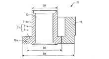
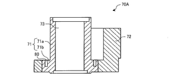
- FIG. 2 is a cross-sectional view showing the structure of the bush of the scroll compressor according to Embodiment 1 of the present invention.
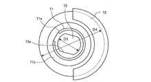
- FIG. 3 is a plan view showing the structure of the bush of the scroll compressor according to Embodiment 1 of the present invention. D1 to D4 in FIGS. 2 and 3 will be described later with reference to FIG.
- the bush 70 has a substantially cylindrical shaft portion 71 and a balance weight portion 72.
- the shaft portion 71 is integrally formed with a substantially cylindrical main body portion 71a and a substantially cylindrical connecting portion 71b extending outwardly on one axial end side (lower end side in FIG. 2) of the main body portion 71a. Have a configuration.
- the balance weight portion 72 has a through hole 72a, and the shaft portion 71 and the balance weight portion 72 are shrink-fitted and joined at the connection portion 71b in a state where the connection portion 71b of the shaft portion 71 is inserted into the through hole 72a. ing.
- the main body portion 71 a of the shaft portion 71 is rotatably fitted in the rocking bearing 18 that supports the rocking scroll 12, and the eccentric pin portion 30 a is cranked in the slide hole 73 formed in the center portion of the shaft portion 71. It is slidably inserted in the radial direction of the shaft 30. Therefore, when the crankshaft 30 rotates, the rotational force is transmitted to the orbiting scroll 12 via the shaft portion 71, and the orbiting scroll 12 revolves. At this time, the bush 70 moves in the radial direction along the flat surface portion 73a of the slide hole 73 by the action of the centrifugal force on the balance weight portion 72, and the orbiting scroll 12 also moves along with this movement. The second spiral body 12 b is pressed against the first spiral body 11 b of the fixed scroll 11. Thus, a driven crank mechanism that improves the sealing performance of the compression chamber 13 is configured.
- the gas refrigerant sucked into the shell 40 from the suction pipe 43 is taken into the compression chamber 13. And the compression chamber 13 which took in gas reduces a volume, moving to a center direction from an outer peripheral part with the eccentric revolving motion of the rocking scroll 12, and compresses a refrigerant
- the orbiting scroll 12 moves in the radial direction together with the bush 70 by its centrifugal force, and the first spiral body 11b and the second spiral body 12b are brought into close contact with each other. Accordingly, refrigerant leakage from the high pressure side to the low pressure side is prevented in the compression chamber 13, and efficient compression is performed.
- the pressing force of the second spiral body 12b against the first spiral body 11b depends on the weight of the orbiting scroll 12, the revolution radius, and the rotational speed of the crankshaft 30. Becomes excessive. In this case, the sliding loss accompanying the sliding of the first spiral body 11b and the second spiral body 12b increases, and the efficiency of the scroll compressor decreases.
- the centrifugal force in the direction 180 ° opposite to the centrifugal force direction of the orbiting scroll 12 acts on the balance weight portion 72 of the bush 70, the bush 70 is rotated 180 degrees with respect to the eccentric pin portion 30a of the crankshaft 30. ° Slide in the opposite radial direction to adjust the pressing force to prevent an increase in sliding loss.
- the main body portion 71a of the shaft portion 71 slides on the boss portion 12c of the rocking scroll 12 via the rocking bearing 18, so that the outer peripheral surface 71aa of the main body portion 71a is as much as possible. It is required to have a flat surface with small undulations.
- the balance weight portion 72 is shrink-fitted and fixed to the shaft portion 71, the shaft portion 71 is deformed in a direction of reducing the outer diameter due to the mutual pressure due to the shrink-fitting. This modification will be described with reference to FIG.
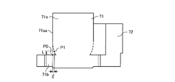
- FIG. 4 is a schematic diagram for explaining the deformation of the shaft portion that occurs when the balance weight portion is shrink-fitted and fixed to the shaft portion of the bush.
- the solid line indicates before deformation
- the dotted line indicates after deformation.
- the main body 71a is deformed so that the boundary with the connecting portion 71b is reduced radially inward.
- the connecting portion 71b is also deformed so that the outer diameter is reduced radially inward. That is, the shaft portion 71 is deformed so that the outer diameter is reduced radially inward in both the main body portion 71a and the connecting portion 71b.
- the balance weight portion 72 is deformed in the direction in which the inner diameter is expanded by mutual pressure due to shrink fitting.
- the positions P0 and P1, the distance L, and the deformation amount ⁇ in FIG. 4 will be described later.
- the bush 70 is designed to satisfy the following conditions (a) and (b) in the first embodiment. Refer to FIGS. 2 and 3 for D1 to D4 in this condition.
- the reason why the conditions (a) and (b) are set is that pressure pressing the shaft portion 71 and the balance weight portion 72 is generated between the shaft portion 71 and the balance weight portion 72 as described above. Therefore, the connecting portion 71b having a larger outer diameter than that of the main body portion 71a is provided in the main body portion 71a, and the thickness of the portion that is shrink-fitted to the balance weight portion 72 is increased to increase the rigidity. Compared with the case where the balance weight part 72 is directly joined without providing the 71b, the deformation amount of the shaft part 71 in the radial direction can be suppressed.
- the rigidity of the shaft portion 71 increases as the outer diameter D1 of the main body portion 71a becomes smaller than the outer diameter D2 of the connecting portion 71b, that is, as the value of “D2 / D1” increases.
- the condition of (a) is the condition that the outer diameter D2 of the connecting portion 71b is larger than the outer diameter D1 of the main body portion 71a.
- the rigidity of the shaft portion 71 increases, the amount of deformation ⁇ when the balance weight portion 72 is shrink-fitted can be reduced.
- the value of “D2 / D1” is increased too much, it is necessary to enlarge the frame 50 from the viewpoint of stowage, and the size of the scroll compressor itself must be changed, resulting in an increase in cost.
- the rigidity of the shaft portion 71 increases as the Young's modulus E1 of the shaft portion 71 is higher than the Young's modulus E2 of the balance weight portion 72, that is, the value of E1 / E2 increases, and the balance weight portion 72 is shrink-fitted.
- the deformation amount ⁇ at the time can be suppressed.
- Young's modulus varies depending on the material, there are limited options available for the compressor.
- the unevenness on the surface of the contact surface between the main body 71a of the bush 70 and the rocking bearing 18 is set to 1.5 ⁇ m or less, depending on the processing accuracy in order to ensure reliability.
- the bearing is designed so that the minimum oil film thickness is about 3 to 5 ⁇ m from the viewpoint of preventing reliability deterioration due to metal contact. Therefore, it is desirable that the deformation amount ⁇ of the shaft portion 71 be less than the minimum oil film thickness of 3 ⁇ m.
- the deformation amount ⁇ can be suppressed to 3 ⁇ m or less, and it is not necessary to enlarge the frame 50 from the viewpoint of storage property, and the above (a), (b) Each condition was set.
- the deformation amount ⁇ can be reduced while preventing the deterioration in manufacturability and the cost by increasing the outer diameter D2 of the connecting portion 71b more than necessary or increasing the Young's modulus E1 of the shaft portion 71 more than necessary.
- the bushing 70 that can be suppressed and has high reliability can be configured.
- FIG. 5 shows the result of measuring the amount of deformation in the radial direction of the shaft portion 71 of the scroll compressor by simulation or the like in the scroll compressor that satisfies the condition (a).
- FIG. 5 is a graph showing the amount of deformation in the radial direction of the shaft portion of the scroll compressor according to Embodiment 1 of the present invention.
- the horizontal axis indicates the distance from the height position P0 of the shrink-fit upper end to the measurement position P1 on the outer peripheral surface 71aa (hereinafter referred to as “distance from the shrink-fit upper end”) L [mm.
- the vertical axis represents the deformation amount ⁇ [ ⁇ m] in the radial direction of the shaft portion 71 at the measurement position P1.
- the amount of deformation ⁇ increases as the distance L from the shrink-fit upper end decreases.
- the deformation amount ⁇ is about ⁇ 7 ⁇ m in the comparative example
- the deformation amount ⁇ is suppressed to about ⁇ 2 ⁇ m
- the deformation amount allowable range is 3 ⁇ m. It turns out that it is less than.
- the smaller the amount of deformation ⁇ the easier it is to secure the oil film of the rocking bearing 18, so that insufficient lubrication can be suppressed. Therefore, it has been confirmed that the reliability of the rocking bearing 18 is improved in the first embodiment compared to the comparative example.
- the shrink-fit fixing portion between the balance weight portion 72 and the connecting portion 71b is required to have a holding force that prevents the balance weight portion 72 from separating from the connecting portion 71b when the crankshaft 30 rotates.
- This holding force increases as the shrink-fitting allowance increases, but if the shrink-fit allowance is excessively increased, the deformation amount ⁇ increases accordingly. Therefore, the lower limit of the shrinkage allowance is set on condition that the necessary holding force is secured, and the upper limit of the shrinkage allowance is set on condition that the deformation amount ⁇ is suppressed to less than 3 ⁇ m as described above.
- the lower limit of the shrinkage allowance is, for example, about 30 ⁇ m considering machining accuracy.
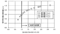
- FIG. 6 is a diagram showing the relationship between “(D2-D3) / (D4-D2) ⁇ E1 / E2” and the maximum amount of deformation in the radial direction of the shaft portion.
- the horizontal axis represents the calculated value of “(D2 ⁇ D3) / (D4 ⁇ D2) ⁇ E1 / E2”, and the vertical axis represents the maximum amount of deformation [ ⁇ m] in the radial direction of the shaft portion 71.
- FIG. 6 shows the amount of deformation in the radial direction of the shaft portion 71 in the axial direction when shrink-fitting is performed with the bush 70 in which the value of “(D2-D3) / (D4-D2) ⁇ E1 / E2” is changed.
- the maximum deformation amount is plotted by changing the symbol according to the magnitude relationship with 3 ⁇ m among the deformation amounts obtained by measurement through simulation and the like. “ ⁇ ” indicates a verification point where the maximum deformation amount is less than 3 ⁇ m, “ ⁇ ” indicates a maximum deformation amount of 3 ⁇ m, and “ ⁇ ” indicates a maximum deformation amount of more than 3 ⁇ m.
- the maximum amount of deformation in the radial direction of the shaft portion 71 can be suppressed to less than 3 ⁇ m, and in order to ensure the reliability of the bearing, “(D2-D3) / (D4-D2) ⁇ E1 / E2 ⁇ It can be seen that “1.0” needs to be satisfied.
- the material of the shaft portion 71 chromium molybdenum steel or a high-strength sintered material is used to ensure high strength and slidability, and the Young's modulus E1 is about 140 to 220 GPa.
- the balance weight portion 72 is made of gray cast iron or graphite cast iron in consideration of the strength and manufacturability due to centrifugal force, and the Young's modulus E2 is about 110 to 170 GPa.
- FIG. 7 is a diagram showing the relationship between “D2 / D1” and “(D2-D3) / (D4-D2) ⁇ E1 / E2”.
- the horizontal axis represents the calculated value of “D2 / D1”
- the vertical axis represents the calculated value of “(D2-D3) / (D4-D2) ⁇ E1 / E2.”
- FIG. 7 shows the radial direction of the shaft portion 71 when shrink fitting is performed with the bush 70 in which the combination of “D2 / D1” and “(D2-D3) / (D4-D2) ⁇ E1 / E2” is changed.
- the deformation amount is measured by simulation or the like in the axial direction, and the maximum deformation amount among the deformation amounts obtained by measurement is plotted by changing the symbol according to the magnitude relationship with 3 ⁇ m. “ ⁇ ” indicates a verification point where the maximum deformation amount is less than 3 ⁇ m, “ ⁇ ” indicates a maximum deformation amount of 3 ⁇ m, and “ ⁇ ” indicates a maximum deformation amount of more than 3 ⁇ m.
- a region surrounded by a thick frame indicates a usable range in which the maximum deformation amount in the radial direction of the shaft portion 71 can be set to less than 3 ⁇ m.
- “D2 / D1 ⁇ 1.2” may be satisfied. Further, from the viewpoint of storage property in the shell 40, “D2 / D1 ⁇ 1.6” was set.
- the shaft portion 71 is subjected to surface treatment such as quenching and tempering for improving strength, nitriding treatment, manganese phosphate treatment, diamond-like carbon (DLC) treatment for improving slidability. Also good.
- surface treatment such as quenching and tempering for improving strength, nitriding treatment, manganese phosphate treatment, diamond-like carbon (DLC) treatment for improving slidability. Also good.
- Both the shaft portion 71 and the balance weight portion 72 use iron-based materials, but when they are not the same material, the linear expansion coefficients are different.
- the bush 70 according to the first embodiment is desirably mounted on a low-pressure shell type compressor in which the bush 70 is arranged in a low-pressure space where the temperature does not increase.
- the compressor that needs to be equipped with the bush 70 is a compressor in which the centrifugal force of the orbiting scroll 12 is excessive.
- the centrifugal force of the orbiting scroll 12 becomes excessive either when the compressor is operated up to a high rotational speed or when the orbiting scroll 12 is heavy. In either case, this is a measure for ensuring the refrigerating capacity, heating, and hot water supply capacity.
- the amount of deformation of the shaft portion 71 can be suppressed and the reliability of the rocking bearing 18 can be secured, which is effective when a single HFO refrigerant or a mixed refrigerant is used as the refrigerant.
- the shaft portion 71 of the bush 70 is connected to the substantially cylindrical main body portion 71a and the substantially cylindrical connection extending outward at one end side in the axial direction of the main body portion 71a. It has a configuration in which the portion 71b is integrally formed, and has a structure in which the rigidity of the shaft portion 71 is increased as compared with a configuration in which the connecting portion 71b is not provided.
- the amount of deformation in the radial direction of the shaft portion 71 during shrink-fitting can be less than 3 ⁇ m.
- the bush 70 is disposed in the low pressure space in the shell 40 and the atmospheric temperature of the bush 70 does not become high, a gap is generated between the shaft portion 71 and the balance weight portion 72 due to the difference in linear expansion coefficient, and the joining is performed. The inconvenience of detachment can be prevented.
- FIG. The second embodiment is different from the first embodiment in the shape of the bush 70, and is otherwise the same as the first embodiment. In the following, the second embodiment will be described focusing on the differences from the first embodiment.
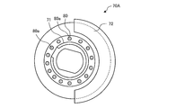
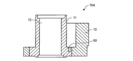
- FIG. 8 is a cross-sectional view of the bush of the scroll compressor according to Embodiment 2 of the present invention.
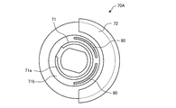
- FIG. 9 is a plan view of the bush of FIG.
- the bush 70A of the scroll compressor according to the second embodiment is provided with a flexible structure 80 that absorbs deformation of the shaft portion 71 at the time of shrink fitting on the connecting portion 71b of the bush 70 according to the first embodiment shown in FIG. It is.
- the flexible structure 80 is configured by a recess provided on the surface on the main body 71a side of both end surfaces in the axial direction of the connecting portion 71b.
- the recess is formed in an annular shape centering on the central axis of the main body 71a.
- the deformation of the shaft portion 71 of the bush 70A at the time of shrink fitting is absorbed, and the deformation amount ⁇ can be made smaller than that of the first embodiment shown in FIG. Specifically, the amount of deformation in the radial direction of the shaft portion 71 can be further suppressed from 3 ⁇ m.
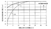
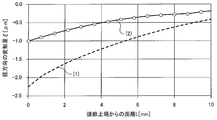
- FIG. 10 is a graph showing the amount of radial deformation of the shaft portion of the scroll compressor according to Embodiment 2 of the present invention.
- the horizontal axis represents the distance L [mm] from the height position P0 of the shrink-fit upper end to the measurement position P1 on the outer peripheral surface 71aa
- the vertical axis represents the radial deformation amount ⁇ [ ⁇ m] at the measurement position P1. It is. Refer to FIG. 4 for P0, P1, and ⁇ .
- (1) shows a graph of the first embodiment
- (2) shows a graph of the second embodiment.
- the deformation amount ⁇ can be made smaller in the second embodiment than in the first embodiment.
- the same effect as in the first embodiment can be obtained, and the deformation amount ⁇ can be further reduced by providing the flexible structure 80. Further, the amount of deformation in the radial direction of the shaft portion 71 can be adjusted by changing the depth and width of the groove of the flexible structure 80.
- liquid back in which liquid refrigerant returns to the oil reservoir 41 may occur.
- the viscosity of the lubricating oil decreases, and the oil film thickness of the rocking bearing 18 becomes transiently less than 3 ⁇ m, and the rocking bearing 18 may seize.
- the deformation amount ⁇ can be further reduced by providing the flexible structure 80, even when the oil film thickness of the rocking bearing 18 becomes transiently thin, such as during liquid back, the oil film thickness is reduced. The thickness can be maintained at 3 ⁇ m or more, and high reliability can be secured.
- the connecting portion 71b of the shaft portion 71 of the bush 70 and the balance weight portion 72 have been described as being joined by shrink fitting, but they may be joined by press-fitting. By adopting the above configuration, the deformation amount ⁇ can be suppressed.
- the bush of the present invention is not limited to the structure shown in each of the above drawings, and can be variously modified as follows without departing from the gist of the present invention.
- FIG. 8 the structure in which the flexible structure 80 is formed by one annular recess that is continuous as a whole is illustrated and described. However, the recess is divided into a plurality of arcs and is formed in an annular shape as a whole. May be.
- FIG. 11 is a plan view showing Modification Example 1 of the flexible structure.
- the flexible structure 80 is configured by arranging a plurality of circular recesses 80a in a ring shape when seen in a plan view.
- FIG. 12 is a cross-sectional view showing Modification Example 2 of the flexible structure.
- 13 is a plan view of the flexible structure of FIG. In FIG. 8, FIG. 9 and FIG. 11, the flexible structure 80 is provided over 360 °.
- the structure is provided with the flexible structure 80 only in a range where the rigidity is high due to the balance weight portion 72 and the deformation due to shrink fitting is large.
- a flexible structure 80 constituted by a concave portion is provided in a range of, for example, 180 ° on the side where the balance weight portion 72 is joined in the connecting portion 71 b.
- the angle range in which the flexible structure 80 is provided is not limited to 180 °, and may be larger or smaller.
- FIG. 13 shows an example in which the flexible structure 80 is configured by an arc-shaped recess when viewed in a plan view. However, as shown in FIG. It is good also as a structure arrange
- FIG. 14 is a plan view showing Modification 3 of the flexible structure.
- the flexible structure 80 of Modification 3 is configured by dividing the flexible structure 80 of Modification 2 shown in FIG. 13 into a plurality (here, two).
Abstract
Description
(a)1.2≦D2/D1≦1.6
(b)1.0≦(D2-D3)/(D4-D2)×E1/E2≦3.5
ここで、D1:本体部の外径、D2:連結部の外径、D3:本体部の内径、D4:バランスウェイト部の外径、E1:軸部のヤング率、E2:バランスウェイト部のヤング率 A scroll compressor according to the present invention forms a compression chamber by combining a fixed scroll and an orbiting scroll with each other, drives the orbiting scroll to compress the fluid in the compression chamber, and a rotational force on the orbiting scroll. A crank shaft that drives the orbiting scroll, an orbiting bearing that supports the orbiting scroll, a shaft portion disposed between the orbiting bearing and the eccentric pin of the crankshaft, and a shaft A bush having a balance weight portion fixed by shrink fitting on the outer periphery of the shaft, the shaft portion being fitted into the rocking bearing, and a cylindrical body portion into which an eccentric pin of the crankshaft is inserted, and a body portion And a cylindrical connecting portion to which the balance weight portion is joined, and the bush satisfies the following conditions (a) and (b).
(A) 1.2 ≦ D2 / D1 ≦ 1.6
(B) 1.0 ≦ (D2-D3) / (D4-D2) × E1 / E2 ≦ 3.5
Here, D1: outer diameter of the main body part, D2: outer diameter of the connecting part, D3: inner diameter of the main body part, D4: outer diameter of the balance weight part, E1: Young's modulus of the shaft part, E2: Young of the balance weight part rate
以下、実施の形態1について説明する。図1は、この発明の実施の形態1に係るスクロール圧縮機の縦概略断面図である。
このスクロール圧縮機は、冷媒等の流体を吸入し、圧縮して高温高圧の状態として吐出させる機能を有している。スクロール圧縮機は、圧縮機構部10と、駆動機構部20と、この圧縮機構部10と駆動機構部20とを連結し、駆動機構部20の発生する回転力を圧縮機構部10に伝達するクランクシャフト30と、その他の構成部品とを有し、これらが外郭を構成するシェル40の内部に収納された構成を有している。そして、シェル40の下部には、潤滑油を貯留する油溜り41が設けられている。油溜り41内には、クランクシャフト30の下端部に固着されたオイルポンプ42が浸漬しており、クランクシャフト30の回転に伴って潤滑油がクランクシャフト30内の油流路31内を通り、圧縮機構部10の各摺動部に供給されるようになっている。
The first embodiment will be described below. FIG. 1 is a schematic vertical sectional view of a scroll compressor according to
This scroll compressor has a function of sucking a fluid such as a refrigerant, compressing it, and discharging it in a high temperature and high pressure state. The scroll compressor includes a
シェル40に設けられた図示省略の電源端子に通電されると、ステータ21とロータ22とにトルクが発生し、クランクシャフト30が回転する。クランクシャフト30の回転力はブッシュ70を介して揺動スクロール12に伝えられ、揺動スクロール12はオルダムリング60により自転を規制されて偏心公転運動する。 Here, the operation of the scroll compressor will be briefly described.
When a power supply terminal (not shown) provided in the
図4に示すように、本体部71aは連結部71bとの境界部分が径方向内側に縮小するように変形する。また、連結部71bも、外径が径方向内側に縮小するように変形を生じる。つまり、軸部71は本体部71a及び連結部71bの両方において外径が径方向内側に縮小するように変形を生じる。一方、バランスウェイト部72は、焼嵌めによる相互圧力で、内径が拡大する方向に変形を生じる。図4における位置P0、P1、距離L及び変形量ξについては後述する。 FIG. 4 is a schematic diagram for explaining the deformation of the shaft portion that occurs when the balance weight portion is shrink-fitted and fixed to the shaft portion of the bush. In FIG. 4, the solid line indicates before deformation, and the dotted line indicates after deformation.
As shown in FIG. 4, the
(b)1.0≦(D2-D3)/(D4-D2)×E1/E2≦3.5
ここで、
D1:本体部71aの外径
D2:連結部71bの外径
D3:本体部71aの内径
D4:バランスウェイト部72の外径
E1:軸部71のヤング率
E2:バランスウェイト部72のヤング率 (A) 1.2 ≦ D2 / D1 ≦ 1.6
(B) 1.0 ≦ (D2-D3) / (D4-D2) × E1 / E2 ≦ 3.5
here,
D1: Outer diameter of
焼嵌め時において、ブッシュ70の軸部71が径方向内側に縮小するのは、上述したように、軸部71とバランスウェイト部72との間で互いに押圧する圧力が生じるからである。よって、本体部71aに、本体部71aよりも外径の大きい連結部71bを設け、バランスウェイト部72に焼嵌めされる部分の肉厚を増して剛性を高めることで、本体部71aに連結部71bを設けずに直接、バランスウェイト部72を接合する場合に比べて、軸部71の径方向の変形量を抑制することができる。 Hereinafter, the reason why the conditions (a) and (b) are set will be described.
The reason why the
実施の形態2は、ブッシュ70の形状が実施の形態1と異なるものであり、それ以外については実施の形態1と同様である。以下、実施の形態2が実施の形態1と異なる部分を中心に説明する。
The second embodiment is different from the first embodiment in the shape of the
実施の形態2のスクロール圧縮機のブッシュ70Aは、図2に示した実施の形態1のブッシュ70の連結部71bに、焼嵌め時の軸部71の変形を吸収する柔構造80を設けたものである。柔構造80は、連結部71bの軸方向両端面のうち本体部71a側の表面に設けられた凹部で構成されている。凹部は、本体部71aの中心軸を中心とした環状に形成されている。 FIG. 8 is a cross-sectional view of the bush of the scroll compressor according to
The
この変形例では、平面的に見て円形状の複数の凹部80aを環状に配置して柔構造80を構成している。 FIG. 11 is a plan view showing Modification Example 1 of the flexible structure.
In this modification, the
上記図8、図9及び図11では、柔構造80を360°に亘って設けていた。これに対し、図12及び図13に示す変形例2では、バランスウェイト部72があることで剛性が高く、焼嵌めによる変形が大きい範囲にのみ、柔構造80を設けた構造とした。ここでは、図13に示したように連結部71bにおいてバランスウェイト部72が接合される側の例えば180゜の範囲に凹部で構成した柔構造80を設けた。なお、柔構造80を設ける角度範囲は180゜に限られたものではなく、更に大きくてもよいし、小さくてもよい。また、図13には柔構造80が平面的に見て円弧状の凹部で構成された例を示しているが、図11に示したように平面的に見て円形状の複数の凹部を円弧状に配置した構成としてもよい。 FIG. 12 is a cross-sectional view showing Modification Example 2 of the flexible structure. 13 is a plan view of the flexible structure of FIG.
In FIG. 8, FIG. 9 and FIG. 11, the
変形例3の柔構造80は、図13に示した変形例2の柔構造80を複数(ここでは2つ)に分割した構成としたものである。 FIG. 14 is a plan
The
Claims (8)
- 固定スクロールと揺動スクロールとを互いに組合せて圧縮室を形成し、前記揺動スクロールを駆動して前記圧縮室内の流体を圧縮する圧縮部と、
前記揺動スクロールに回転力を伝える偏心ピン部を有し、前記揺動スクロールを駆動するクランクシャフトと、
前記揺動スクロールを支持する揺動軸受と、
前記揺動軸受と前記クランクシャフトの偏心ピンとの間に配置された軸部と、前記軸部の外周に焼嵌固定されたバランスウェイト部とを有するブッシュとを備え、
前記軸部は、前記揺動軸受に嵌め込まれ、且つ前記クランクシャフトの偏心ピンが挿入される円筒形状の本体部と、前記本体部の軸方向の端部から外方に延出し、前記バランスウェイト部が接合される円筒形状の連結部とを備え、
前記ブッシュは以下の(a)、(b)の条件を満たすスクロール圧縮機。
(a)1.2≦D2/D1≦1.6
(b)1.0≦(D2-D3)/(D4-D2)×E1/E2≦3.5
ここで、
D1:本体部の外径
D2:連結部の外径
D3:本体部の内径
D4:バランスウェイト部の外径
E1:軸部のヤング率
E2:バランスウェイト部のヤング率 A compression unit that combines a fixed scroll and an orbiting scroll to form a compression chamber, and that drives the orbiting scroll to compress the fluid in the compression chamber;
A crankshaft having an eccentric pin portion for transmitting a rotational force to the swing scroll, and driving the swing scroll;
A rocking bearing for supporting the rocking scroll;
A bush having a shaft portion disposed between the rocking bearing and the eccentric pin of the crankshaft, and a balance weight portion fixed by shrinkage to the outer periphery of the shaft portion;
The shaft portion is fitted into the rocking bearing and has a cylindrical main body portion into which an eccentric pin of the crankshaft is inserted, and extends outward from an axial end portion of the main body portion. A cylindrical connecting part to which the parts are joined,
The bush is a scroll compressor that satisfies the following conditions (a) and (b).
(A) 1.2 ≦ D2 / D1 ≦ 1.6
(B) 1.0 ≦ (D2-D3) / (D4-D2) × E1 / E2 ≦ 3.5
here,
D1: Outer diameter of main body part D2: Outer diameter of connecting part D3: Inner diameter of main body part D4: Outer diameter of balance weight part E1: Young's modulus of shaft part E2: Young's modulus of balance weight part - 前記連結部は、前記バランスウェイト部との接合時の前記軸部の変形を吸収する柔構造を備えた請求項1記載のスクロール圧縮機。 The scroll compressor according to claim 1, wherein the connecting portion includes a flexible structure that absorbs deformation of the shaft portion when joined to the balance weight portion.
- 前記柔構造は、前記連結部の前記軸方向両端面のうち前記本体部側の端面に形成された1又は複数の凹部である請求項2記載のスクロール圧縮機。 3. The scroll compressor according to claim 2, wherein the flexible structure is one or a plurality of concave portions formed on an end surface on the main body portion side of the axially opposite end surfaces of the connecting portion.
- 前記凹部は、
平面的に見て前記本体部の中心軸を中心とした環状若しくは円弧状、又は平面的に見て円形状である請求項3記載のスクロール圧縮機。 The recess is
4. The scroll compressor according to claim 3, wherein the scroll compressor has an annular shape or an arc shape centering on a central axis of the main body portion when seen in a plan view, or a circular shape when seen in a plan view. - 前記ブッシュは鉄系材料でありヤング率が140[GPa]≦E1≦220[GPa]、
前記バランスウェイト部は鉄系材料でありヤング率が110[GPa]≦E2≦170[GPa]である請求項1~請求項4の何れか一項に記載のスクロール圧縮機。 The bush is an iron-based material and has a Young's modulus of 140 [GPa] ≦ E1 ≦ 220 [GPa],
The scroll compressor according to any one of claims 1 to 4, wherein the balance weight portion is an iron-based material and has a Young's modulus of 110 [GPa] ≤ E2 ≤ 170 [GPa]. - 前記ブッシュ及び前記バランスウェイト部は、前記圧縮部、前記クランクシャフトを収納するシェル内の低圧空間に配置される請求項1~請求項5の何れか一項に記載のスクロール圧縮機。 The scroll compressor according to any one of claims 1 to 5, wherein the bush and the balance weight portion are arranged in a low-pressure space in a shell that houses the compression portion and the crankshaft.
- 前記流体は、分子式がC3HmFn(但し、m及びnは1以上5以下の整数で、m+n=6の関係が成立する。)で表され、且つ分子構造中に二重結合を1個有する冷媒、又は、前記冷媒を含む混合冷媒である請求項1~請求項6の何れか一項に記載のスクロール圧縮機。 The fluid has a molecular formula of C 3 H m F n (where m and n are integers of 1 to 5, and a relationship of m + n = 6 is established), and a double bond is formed in the molecular structure. The scroll compressor according to any one of claims 1 to 6, wherein the scroll compressor is one refrigerant or a mixed refrigerant containing the refrigerant.
- 前記流体は、2,3,3,3-テトラフルオロ-1-プロペンであることを特徴とする請求項1~請求項7の何れか一項に記載のスクロール圧縮機。 The scroll compressor according to any one of claims 1 to 7, wherein the fluid is 2,3,3,3-tetrafluoro-1-propene.
Priority Applications (5)
| Application Number | Priority Date | Filing Date | Title |
|---|---|---|---|
| CN201680080809.7A CN108603500B (en) | 2016-02-09 | 2016-02-09 | Scroll compressor having a plurality of scroll members |
| JP2017566450A JP6400237B2 (en) | 2016-02-09 | 2016-02-09 | Scroll compressor |
| PCT/JP2016/053859 WO2017138098A1 (en) | 2016-02-09 | 2016-02-09 | Scroll compressor |
| EP16889800.5A EP3415760B1 (en) | 2016-02-09 | 2016-02-09 | Scroll compressor |
| US15/781,781 US10968912B2 (en) | 2016-02-09 | 2016-02-09 | Scroll compressor |
Applications Claiming Priority (1)
| Application Number | Priority Date | Filing Date | Title |
|---|---|---|---|
| PCT/JP2016/053859 WO2017138098A1 (en) | 2016-02-09 | 2016-02-09 | Scroll compressor |
Publications (1)
| Publication Number | Publication Date |
|---|---|
| WO2017138098A1 true WO2017138098A1 (en) | 2017-08-17 |
Family
ID=59563008
Family Applications (1)
| Application Number | Title | Priority Date | Filing Date |
|---|---|---|---|
| PCT/JP2016/053859 WO2017138098A1 (en) | 2016-02-09 | 2016-02-09 | Scroll compressor |
Country Status (5)
| Country | Link |
|---|---|
| US (1) | US10968912B2 (en) |
| EP (1) | EP3415760B1 (en) |
| JP (1) | JP6400237B2 (en) |
| CN (1) | CN108603500B (en) |
| WO (1) | WO2017138098A1 (en) |
Cited By (2)
| Publication number | Priority date | Publication date | Assignee | Title |
|---|---|---|---|---|
| WO2019026272A1 (en) * | 2017-08-04 | 2019-02-07 | 三菱電機株式会社 | Scroll compressor |
| WO2023106116A1 (en) * | 2021-12-08 | 2023-06-15 | サンデン株式会社 | Scroll-type fluid machine |
Families Citing this family (3)
| Publication number | Priority date | Publication date | Assignee | Title |
|---|---|---|---|---|
| CN110206728B (en) * | 2019-05-14 | 2020-11-24 | 珠海格力节能环保制冷技术研究中心有限公司 | Scroll compressor and air conditioner |
| FR3102792B1 (en) * | 2019-11-05 | 2021-10-29 | Danfoss Commercial Compressors | Scroll compressor comprising a crank pin having an upper recess |
| DE102021210295A1 (en) | 2021-09-16 | 2023-03-16 | Brose Fahrzeugteile SE & Co. Kommanditgesellschaft, Würzburg | scroll machine |
Citations (2)
| Publication number | Priority date | Publication date | Assignee | Title |
|---|---|---|---|---|
| JPH10281083A (en) * | 1997-04-04 | 1998-10-20 | Mitsubishi Electric Corp | Scroll compressor |
| JP2003239881A (en) * | 2002-02-20 | 2003-08-27 | Fujitsu General Ltd | Scroll compressor |
Family Cites Families (11)
| Publication number | Priority date | Publication date | Assignee | Title |
|---|---|---|---|---|
| US5199862A (en) * | 1990-07-24 | 1993-04-06 | Mitsubishi Jukogyo Kabushiki Kaisha | Scroll type fluid machinery with counter weight on drive bushing |
| JP3026672B2 (en) | 1992-04-10 | 2000-03-27 | 三洋電機株式会社 | Scroll compressor |
| JP2000220585A (en) * | 1999-01-28 | 2000-08-08 | Toyota Autom Loom Works Ltd | Scroll type compressor |
| JP2002089468A (en) * | 2000-09-14 | 2002-03-27 | Toyota Industries Corp | Scroll type compressor |
| JP2002106483A (en) * | 2000-09-29 | 2002-04-10 | Toyota Industries Corp | Scroll type compressor and sealing method therefor |
| JP3858762B2 (en) * | 2002-05-29 | 2006-12-20 | ダイキン工業株式会社 | Slide bush and scroll type fluid machine |
| JP2004124834A (en) * | 2002-10-03 | 2004-04-22 | Mitsubishi Electric Corp | Hermetically sealed rotary compressor |
| CN102046981A (en) * | 2008-05-28 | 2011-05-04 | 东芝开利株式会社 | Enclosed compressor and refrigeration cycle device |
| JP2012057499A (en) * | 2010-09-06 | 2012-03-22 | Toyota Industries Corp | Electric compressor |
| WO2015068308A1 (en) * | 2013-11-11 | 2015-05-14 | 三菱電機株式会社 | Scroll compressor |
| WO2017168631A1 (en) * | 2016-03-30 | 2017-10-05 | 三菱電機株式会社 | Scroll compressor and refrigeration cycle device |
-
2016
- 2016-02-09 JP JP2017566450A patent/JP6400237B2/en active Active
- 2016-02-09 WO PCT/JP2016/053859 patent/WO2017138098A1/en active Application Filing
- 2016-02-09 EP EP16889800.5A patent/EP3415760B1/en active Active
- 2016-02-09 US US15/781,781 patent/US10968912B2/en active Active
- 2016-02-09 CN CN201680080809.7A patent/CN108603500B/en active Active
Patent Citations (2)
| Publication number | Priority date | Publication date | Assignee | Title |
|---|---|---|---|---|
| JPH10281083A (en) * | 1997-04-04 | 1998-10-20 | Mitsubishi Electric Corp | Scroll compressor |
| JP2003239881A (en) * | 2002-02-20 | 2003-08-27 | Fujitsu General Ltd | Scroll compressor |
Non-Patent Citations (1)
| Title |
|---|
| See also references of EP3415760A4 * |
Cited By (3)
| Publication number | Priority date | Publication date | Assignee | Title |
|---|---|---|---|---|
| WO2019026272A1 (en) * | 2017-08-04 | 2019-02-07 | 三菱電機株式会社 | Scroll compressor |
| JPWO2019026272A1 (en) * | 2017-08-04 | 2019-11-21 | 三菱電機株式会社 | Scroll compressor |
| WO2023106116A1 (en) * | 2021-12-08 | 2023-06-15 | サンデン株式会社 | Scroll-type fluid machine |
Also Published As
| Publication number | Publication date |
|---|---|
| JPWO2017138098A1 (en) | 2018-04-26 |
| CN108603500A (en) | 2018-09-28 |
| EP3415760A1 (en) | 2018-12-19 |
| US20180363653A1 (en) | 2018-12-20 |
| JP6400237B2 (en) | 2018-10-03 |
| CN108603500B (en) | 2020-09-18 |
| US10968912B2 (en) | 2021-04-06 |
| EP3415760A4 (en) | 2018-12-19 |
| EP3415760B1 (en) | 2021-09-15 |
Similar Documents
| Publication | Publication Date | Title |
|---|---|---|
| JP6400237B2 (en) | Scroll compressor | |
| EP3138994B1 (en) | Scroll compressor | |
| JP4162708B2 (en) | Expander integrated compressor | |
| US10859083B2 (en) | Scroll compressor | |
| US20090098000A1 (en) | Scroll compressor with scroll deflection compensation | |
| JP6057535B2 (en) | Refrigerant compressor | |
| JP5017842B2 (en) | Rotary compressor | |
| US11441565B2 (en) | Compressor having Oldham's ring | |
| JP5034975B2 (en) | Scroll compressor | |
| JP6463514B2 (en) | Slider and scroll compressor with balancer | |
| JPH0893672A (en) | Hermetic compressor and scroll compressor | |
| JP4749136B2 (en) | Scroll compressor | |
| JP5864883B2 (en) | Scroll compressor | |
| WO2015049745A1 (en) | Scroll compressor | |
| JP2008121490A (en) | Rotary compressor | |
| JP2016156297A (en) | Scroll compressor | |
| EP3705723B1 (en) | Scroll compressor | |
| EP4212726A1 (en) | Scroll compressor | |
| WO2017122304A1 (en) | Scroll compressor | |
| JP2017198133A (en) | Scroll compressor | |
| JP5229129B2 (en) | Scroll compressor | |
| WO2017212527A1 (en) | Scroll compressor | |
| JP2012036841A (en) | Compressor | |
| JP2003139078A (en) | Compressor | |
| JP2010077918A (en) | Scroll compressor |
Legal Events
| Date | Code | Title | Description |
|---|---|---|---|
| 121 | Ep: the epo has been informed by wipo that ep was designated in this application |
Ref document number: 16889800 Country of ref document: EP Kind code of ref document: A1 |
|
| ENP | Entry into the national phase |
Ref document number: 2017566450 Country of ref document: JP Kind code of ref document: A |
|
| NENP | Non-entry into the national phase |
Ref country code: DE |
|
| WWE | Wipo information: entry into national phase |
Ref document number: 2016889800 Country of ref document: EP |
|
| ENP | Entry into the national phase |
Ref document number: 2016889800 Country of ref document: EP Effective date: 20180910 |