WO2017135418A1 - ユーザ端末、無線基地局及び無線通信方法 - Google Patents
ユーザ端末、無線基地局及び無線通信方法 Download PDFInfo
- Publication number
- WO2017135418A1 WO2017135418A1 PCT/JP2017/004010 JP2017004010W WO2017135418A1 WO 2017135418 A1 WO2017135418 A1 WO 2017135418A1 JP 2017004010 W JP2017004010 W JP 2017004010W WO 2017135418 A1 WO2017135418 A1 WO 2017135418A1
- Authority
- WO
- WIPO (PCT)
- Prior art keywords
- downlink control
- transmission
- unit
- subframe
- dci
- Prior art date
Links
Images


Classifications
-
- H—ELECTRICITY
- H04—ELECTRIC COMMUNICATION TECHNIQUE
- H04L—TRANSMISSION OF DIGITAL INFORMATION, e.g. TELEGRAPHIC COMMUNICATION
- H04L1/00—Arrangements for detecting or preventing errors in the information received
- H04L1/12—Arrangements for detecting or preventing errors in the information received by using return channel
- H04L1/16—Arrangements for detecting or preventing errors in the information received by using return channel in which the return channel carries supervisory signals, e.g. repetition request signals
- H04L1/18—Automatic repetition systems, e.g. Van Duuren systems
- H04L1/1812—Hybrid protocols; Hybrid automatic repeat request [HARQ]
- H04L1/1816—Hybrid protocols; Hybrid automatic repeat request [HARQ] with retransmission of the same, encoded, message
-
- H—ELECTRICITY
- H04—ELECTRIC COMMUNICATION TECHNIQUE
- H04L—TRANSMISSION OF DIGITAL INFORMATION, e.g. TELEGRAPHIC COMMUNICATION
- H04L5/00—Arrangements affording multiple use of the transmission path
- H04L5/003—Arrangements for allocating sub-channels of the transmission path
- H04L5/0053—Allocation of signaling, i.e. of overhead other than pilot signals
-
- H—ELECTRICITY
- H04—ELECTRIC COMMUNICATION TECHNIQUE
- H04L—TRANSMISSION OF DIGITAL INFORMATION, e.g. TELEGRAPHIC COMMUNICATION
- H04L5/00—Arrangements affording multiple use of the transmission path
- H04L5/003—Arrangements for allocating sub-channels of the transmission path
- H04L5/0058—Allocation criteria
- H04L5/0064—Rate requirement of the data, e.g. scalable bandwidth, data priority
-
- H—ELECTRICITY
- H04—ELECTRIC COMMUNICATION TECHNIQUE
- H04L—TRANSMISSION OF DIGITAL INFORMATION, e.g. TELEGRAPHIC COMMUNICATION
- H04L5/00—Arrangements affording multiple use of the transmission path
- H04L5/003—Arrangements for allocating sub-channels of the transmission path
- H04L5/0078—Timing of allocation
- H04L5/0082—Timing of allocation at predetermined intervals
-
- H—ELECTRICITY
- H04—ELECTRIC COMMUNICATION TECHNIQUE
- H04L—TRANSMISSION OF DIGITAL INFORMATION, e.g. TELEGRAPHIC COMMUNICATION
- H04L5/00—Arrangements affording multiple use of the transmission path
- H04L5/0091—Signaling for the administration of the divided path
- H04L5/0092—Indication of how the channel is divided
-
- H—ELECTRICITY
- H04—ELECTRIC COMMUNICATION TECHNIQUE
- H04W—WIRELESS COMMUNICATION NETWORKS
- H04W4/00—Services specially adapted for wireless communication networks; Facilities therefor
- H04W4/70—Services for machine-to-machine communication [M2M] or machine type communication [MTC]
-
- H—ELECTRICITY
- H04—ELECTRIC COMMUNICATION TECHNIQUE
- H04W—WIRELESS COMMUNICATION NETWORKS
- H04W72/00—Local resource management
- H04W72/04—Wireless resource allocation
- H04W72/044—Wireless resource allocation based on the type of the allocated resource
- H04W72/0446—Resources in time domain, e.g. slots or frames
-
- H—ELECTRICITY
- H04—ELECTRIC COMMUNICATION TECHNIQUE
- H04W—WIRELESS COMMUNICATION NETWORKS
- H04W72/00—Local resource management
- H04W72/20—Control channels or signalling for resource management
- H04W72/23—Control channels or signalling for resource management in the downlink direction of a wireless link, i.e. towards a terminal
-
- H—ELECTRICITY
- H04—ELECTRIC COMMUNICATION TECHNIQUE
- H04L—TRANSMISSION OF DIGITAL INFORMATION, e.g. TELEGRAPHIC COMMUNICATION
- H04L5/00—Arrangements affording multiple use of the transmission path
- H04L5/003—Arrangements for allocating sub-channels of the transmission path
- H04L5/0044—Arrangements for allocating sub-channels of the transmission path allocation of payload
-
- H—ELECTRICITY
- H04—ELECTRIC COMMUNICATION TECHNIQUE
- H04W—WIRELESS COMMUNICATION NETWORKS
- H04W72/00—Local resource management
- H04W72/12—Wireless traffic scheduling
- H04W72/1263—Mapping of traffic onto schedule, e.g. scheduled allocation or multiplexing of flows
- H04W72/1268—Mapping of traffic onto schedule, e.g. scheduled allocation or multiplexing of flows of uplink data flows
Definitions
- the present invention relates to a user terminal, a radio base station, and a radio communication method in a next-generation mobile communication system.
- LTE Long Term Evolution
- Non-Patent Document 1 LTE-Advanced
- FRA Full Radio Access
- 4G, 5G, LTE Rel. 13, 14, 15 ⁇ LTE successor systems
- inter-device communication M2M: Machine-to-Machine
- MTC Machine Type Communication
- 3GPP Third Generation Partnership Project
- MTC user terminals MTC UE (User Equipment)
- MTC UE User Equipment
- 3GPP TS 36.300 “Evolved Universal Terrestrial Radio Access (E-UTRA) and Evolved Universal Terrestrial Radio Access Network (E-UTRAN); Overall description; Stage 2”
- 3GPP TR 36.888 “Study on provision of low-cost Machine-Type Communications (MTC) User Equipments (UEs) based on LTE (Release 12)”
- MTC Machine-Type Communications
- UEs User Equipments
- LC-MTC Low-Cost -MTC terminal
- LC-MTC UE LTE communication in a very narrow band
- NB-IoT Near Band Internet of Things
- NB-LTE Narrow Band LTE
- NB cellular IoT Narrow Band cellular Internet of Things
- NB-IoT described in this specification includes the above-mentioned NB-LTE, NB cellular IoT, clean slate, and the like.
- NB-IoT terminals The bandwidth used by user terminals that support NB-IoT (hereinafter referred to as NB-IoT terminals) is narrower than the minimum system bandwidth (1.4 MHz) of existing LTE systems (for example, LTE systems prior to Rel.12). It is also assumed that the bandwidth is limited to, for example, 180 kHz, 1 resource block (RB: Resource Block, PRB: Physical Resource Block, etc.).
- RB Resource Block
- PRB Physical Resource Block
- PRB which is a resource allocation unit in the LTE system It is assumed that resource allocation in smaller frequency units (for example, subcarrier units) is required.
- the present invention has been made in view of the above point, and appropriately performs communication even when allocation is controlled in a frequency unit (for example, subcarrier unit) smaller than a resource allocation unit in an existing LTE system.
- Another object is to provide a user terminal, a radio base station, and a radio communication method that can be used.
- a user terminal includes a receiving unit that receives downlink control information on a downlink control channel included in a predetermined period in a predetermined bandwidth, and a control unit that controls uplink data transmission based on the downlink control information
- the control unit controls the start timing of uplink data transmission based on a subframe in which the downlink control channel is transmitted last in the predetermined period.
- communication can be appropriately performed even when the allocation is controlled in a frequency unit (for example, subcarrier unit) smaller than the resource allocation unit in the existing LTE system.
- a frequency unit for example, subcarrier unit
- 2A and 2B are diagrams illustrating an example of a resource unit in NB-IoT.
- 3A and 3B are diagrams illustrating an example of a subframe set.
- 4A and 4B are diagrams illustrating another example of a subframe set. It is a figure which shows an example of UL transmission using the timing of the existing system. It is a figure which shows the other example of UL transmission using the timing of the existing system. It is a figure which shows an example of UL transmission which concerns on this Embodiment. It is a figure which shows the other example of UL transmission which concerns on this Embodiment.
- FIG. 11A and 11B are diagrams illustrating an example of DL transmission according to the present embodiment.
- 12A and 12B are diagrams illustrating another example of DL transmission according to the present embodiment.
- NB-IoT terminals In NB-IoT terminals, it has been studied to allow a reduction in processing capability and simplify the hardware configuration. For example, in NB-IoT terminals, compared to existing user terminals (for example, LTE terminals before Rel.12), the peak rate is reduced, the transport block size (TBS) is limited, and the resource block (RB) : Resource Block, PRB (Physical Resource Block, etc.) restrictions, and RF (Radio Frequency) restrictions are being considered.
- TSS transport block size
- RB resource block
- PRB Physical Resource Block, etc.
- RF Radio Frequency
- the upper limit of the use band of the NB-IoT terminal is a predetermined narrow band (NB: Narrow Band, For example, it is limited to 180 kHz and 1.4 MHz.
- the predetermined narrow band is the same as the minimum system band (for example, 1.4 MHz, 6 PRB) of an existing LTE system (LTE system before Rel.12, hereinafter, also simply referred to as LTE system), or A part of the band (for example, 180 kHz, 1 PRB) may be used.
- the NB-IoT terminal transmits and / or receives (hereinafter, referred to as a terminal having a narrower upper limit of the use band than the existing LTE terminal and a band narrower than the existing LTE terminal (for example, a band narrower than 1.4 MHz). It can also be said that the terminal is capable of transmitting and receiving).
- this NB-IoT terminal is considered to operate within the system band of the LTE system.
- frequency multiplexing may be supported between an NB-IoT terminal whose band is limited and an existing LTE terminal whose band is not limited.
- NB-IoT may be operated using a guard band or a dedicated frequency between carriers adjacent to the LTE system band as well as within the LTE system band.
- FIG. 1 is a diagram showing an arrangement example of a narrow band that is a use band of an NB-IoT terminal.
- the use band of the NB-IoT terminal is set to a part of the system band (for example, 20 MHz) of the LTE system.
- the use band of the NB-IoT terminal is set to 180 kHz, but the present invention is not limited to this.
- the use band of the NB-IoT terminal may be narrower than the system band (for example, 20 MHz) of the LTE system.
- the bandwidth may be equal to or less than 13 LC-MTC terminals (for example, 1.4 MHz).
- the narrow band frequency position used as the use band of the NB-IoT terminal can be changed within the system band.
- the NB-IoT terminal preferably communicates using different frequency resources for each predetermined period (for example, subframe).
- the NB-IoT terminal preferably has an RF retuning function in consideration of application of frequency hopping and frequency scheduling.
- the NB-IoT terminal may use different bands for downlink and uplink, or may use the same band.
- a band used for downlink transmission / reception may be called a downlink narrow band (DL NB).
- a band used for uplink transmission / reception may be called an uplink narrow band (UL NB).
- the NB-IoT terminal receives downlink control information (DCI: Downlink Control Information) using a downlink control channel allocated in a narrow band.
- DCI Downlink Control Information
- the downlink control channel may be called PDCCH (Physical Downlink Control Channel), EPDCCH (Enhanced Physical Downlink Control Channel), M-PDCCH (MTC PDCCH), NB-PDCCH, etc. May be called.
- the NB-IoT terminal receives downlink data using a downlink shared channel arranged in a narrow band.
- the downlink shared channel may be called PDSCH (Physical Downlink Shared Channel), M-PDSCH (MTC PDSCH), NB-PDSCH, or the like.
- the NB-IoT terminal uses an uplink control channel arranged in a narrow band, and transmits uplink control information (HARQ-ACK: Hybrid Automatic Repeat reQuest-ACKnowledge), channel state information (CSI: Channel State Information), etc.
- Control information (UCI: Uplink Control Information) is transmitted.
- the uplink control channel may be referred to as PUCCH (Physical Uplink Control Channel), or may be referred to as M-PUCCH (MTC PUCCH), NB-PUCCH, or the like.
- the NB-IoT terminal receives UCI and / or uplink data using an uplink shared channel arranged in a narrow band.
- the uplink shared channel may be called PUSCH (Physical Uplink Shared Channel), or may be called M-PUSCH (MTC PUSCH), NB-PUSCH, or the like.
- the present invention is not limited to the above channels, and a conventional channel used for the same application may be represented by adding “M” indicating MTC, “N” indicating NB-IoT, or “NB”.
- M MTC
- N indicating NB-IoT
- NB NB-IoT
- the downlink control channel, downlink shared channel, uplink shared channel, and uplink shared channel used in the narrow band are referred to as PDCCH, PDSCH, PUCCH, and PUSCH, respectively, but as described above, the names are not limited to these. .
- the same downlink signal eg, PDCCH, PDSCH, etc.
- / or uplink signal eg, PUCCH, PUSCH, etc.
- Transmission / reception may be performed.
- the number of subframes in which the same downlink signal and / or uplink signal is transmitted / received is also referred to as a repetition number. Further, the number of repetitions may be indicated by a repetition level.
- the repetition level may be referred to as a coverage enhancement (CE) level.
- CE coverage enhancement
- a tone is synonymous with a subcarrier and means each band obtained by dividing a use band (for example, 180 kHz, one resource block).
- single tone transmission it has been studied to support the same subcarrier interval (that is, 15 kHz) as that of the existing LTE system and a subcarrier interval (for example, 3.75 kHz) that is narrower than that of the LTE system.
- a subcarrier interval for example, 3.75 kHz
- multi-tone transmission it is considered to support the same subcarrier interval (that is, 15 kHz) as the LTE system.
- the subcarrier interval is 15 kHz
- 1 PRB 180 kHz
- 1 PRB is configured by 48 subcarriers.
- the subcarrier interval applicable in the present embodiment is not limited to these.
- the NB-IoT terminal performs uplink transmission (for example, PUSCH or / and PUCCH transmission) with the number of tones (subcarriers) notified from the radio base station. For example, ⁇ 1, 3, 6, 12 ⁇ can be considered as a combination of the numbers of tones. In this way, the number of tones selected from a predetermined combination is configured by higher layer signaling (for example, RRC (Radio Resource Control) signaling or broadcast information), and the NB-IoT terminal is configured. Uplink transmission may be performed with the set number of tones.
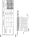
- FIG. 2 is a diagram illustrating an example of a resource unit in NB-IoT.
- FIG. 2A illustrates a case where ⁇ 1, 3, 6, 12 ⁇ is used as the combination of the number of tones (subcarriers), the combination of the number of tones is not limited to this. For example, a combination of ⁇ 1, 2, 4, 12 ⁇ may be used.
- the time unit of one resource unit is changed according to the number of tones constituting one resource unit (that is, the number of subcarriers and frequency units). Specifically, the time unit constituting one resource unit becomes longer as the number of tones (subcarriers) constituting one resource and / or the subcarrier interval decreases.
- the time unit of one resource unit is 1 ms, respectively. 2 ms, 4 ms, and 8 ms.
- the subcarrier interval is 3.75 kHz, which is 1/4 times that of the existing LTE system, and the number of tones is 1, the time unit of one resource unit is 32 ms.
- FIG. 2B shows an example of uplink data (for example, PUSCH) transmission when the number of tones is 1 (single tone).
- uplink data for example, PUSCH
- PUSCH uplink data
- FIG. 2B shows an example of uplink data (for example, PUSCH) transmission when the number of tones is 1 (single tone).
- NB-IoT as shown in FIG. 2B, transmission can be controlled by mapping uplink data of different user terminals to different subcarriers in the same resource block.
- one transport block (TB) which is a data storage unit may be mapped to one resource unit or may be mapped to a plurality of resource units. Further, the resource unit as described above can be applied not only to uplink transmission but also to downlink transmission.
- NB-IoT since a communication band is very limited (for example, 1 RB (180 kHz)), a configuration in which a plurality of consecutive subframes are set for transmission of a downlink control channel (NB-PDCCH) is conceivable. .
- NB-PDCCH downlink control channel
- a continuous subframe set for NB-PDCCH transmission or reception is also referred to as a subframe set, a continuous subframe set, or a control region.
- Information on the subframe set can be notified from the radio base station to the user terminal using higher layer signaling (for example, RRC signaling, broadcast information, etc.) and / or downlink control information.
- the radio base station can control transmission of downlink control information (UL grant and / or DL assignment) by assigning a downlink control channel to a subframe set for the downlink control channel of NB-IoT.
- the user terminal receives a downlink control channel (downlink control information) included in the subframe set, and controls reception of DL data and / or transmission of UL data scheduled with the downlink control information.
- DCI downlink control information
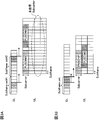
- FIG. 3A shows a case where one DCI is assigned to each of the first subframe set (Subframe set # 1) and the second subframe set (Subframe set # 2).
- FIG. 3A shows a case where one DCI (for example, DCI corresponding to 1 TB) is allocated over two subframes (one DCI is transmitted using two subframes).
- one DCI for example, DCI corresponding to 1 TB
- the method for assigning one DCI is not limited to this.
- the user terminal performs single-tone UL data transmission in a subframe after a predetermined period (for example, after 4 ms) after receiving the downlink control channel (DCI).
- a predetermined period for example, after 4 ms
- DCI downlink control channel
- the user terminal acquires data allocation information from the DCI decoded in subframe #n in which the downlink control channel is transmitted, and after a predetermined period of the subframe #n. and it receives downlink data from subframe # n + k 1. Further, the user terminal starts transmission of uplink data from subframe # n + k 2 after a predetermined period of subframe #n that has received the downlink control channel.
- the uplink data (for example, PUSCH # 1, PUSCH # 2) scheduled by each DCI is allocated to different time regions (subframes) of the same subcarrier.
- resources unused subcarriers
- FIG. 3B shows a case where a plurality (two in this case) of DCIs are assigned to one subframe set.
- FIG. 3B shows a case where one DCI is assigned over two subframes and two DCIs are assigned to consecutive subframes.
- the user terminal performs single-tone UL data transmission in a subframe after a predetermined period (for example, after 4 ms) after receiving the downlink control channel.
- the UL data (PUSCH # 1 and PUSCH # 2) scheduled for each DCI can be assigned so as to overlap in the time domain (subframe), so frequency division Different subcarriers are assigned by multiplexing.
- the number of subcarriers not used in one PRB can be reduced, and resource utilization efficiency can be improved to some extent.
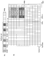
- FIG. 4A shows a case where a plurality of DCIs (DCI # 1- # 3) to which repetitive transmission is not applied are included in the same subframe set
- FIG. 4B shows a plurality of cases where repetitive transmission (repetition number 4 here) is applied.
- the DCI (DCI # 1, # 2) are included in the same subframe set.
- UL data (PUSCH # 1) scheduled by the first DCI # 1 with early allocation timing, and UL data (PUSCH # 2) scheduled by the second DCI # 2 and the third DCI # 3, respectively. , # 3) are partially assigned to the same time domain. For this reason, control is performed so that these UL data are allocated to different subcarriers.
- the UL data (PUSCH # 1) scheduled in the first DCI # 1 and the UL data (PUSCH # 4) scheduled in the fourth DCI # 4 do not overlap in the time domain, so the same sub It is conceivable to control allocation using a carrier.
- an unused resource (Resource fragment) is generated between the first DCI # 1 UL data (PUSCH # 1) and the fourth DCI # 4 UL data (PUSCH # 4).
- the second DCI # 2 UL data (PUSCH # 2) and the fifth DCI # 5 UL data (PUSCH # 5)
- the third DCI # 3 UL data (PUSCH # 3) and Resources that are not used are also generated during the UL data (PUSCH # 6) of the sixth DCI # 6.
- FIG. 6 shows a case where two DCIs (DCI # 1, DCI # 2) to which repetitive transmission (repetition number 4) is applied are provided.
- the user terminal uses the reception timing of the last DCI (the DCI transmitted for the fourth time) as a reference. It is necessary to control the transmission of UL data.
- the allocation position of the uplink data (here, PUSCH # 1, PUSCH # 2) is determined by the position of DCI that is repeatedly transmitted. For this reason, uplink data (here, PUSCH # 1, PUSCH # 2) cannot be efficiently allocated depending on the position of DCI and the number of repetitions, and resource utilization efficiency cannot be sufficiently improved.
- the present inventors pay attention to the fact that when multiple DCIs are included in the same subframe set, if existing transmission timing is used, unused resources (resource fragments) are generated in the time direction in UL data allocation.
- the idea was to control the transmission start timing of UL data scheduled by DCI included in the same subframe set to be the same.
- uplink data transmission scheduled with DCI (UL grant) included in the same subframe set is controlled to start from a predetermined subframe. Accordingly, even when uplink data allocation is controlled by including a plurality of DCIs in the same subframe set, it is possible to suppress the occurrence of unused resources between different uplink data (particularly in the time direction). The utilization efficiency of can be improved.
- the use band of the NB-IoT terminal is limited to 180 kHz (1 PRB), which is a narrower band than the minimum system band (1.4 MHz) of the existing LTE system. I can't.
- the band used by the NB-IoT terminal is narrower than the system band of the existing LTE system, such as 1.4 MHz equal to the minimum system band of the existing LTE system or a band narrower than 180 kHz. Any bandwidth can be used.
- the subcarrier interval is 15 kHz and 180 kHz is composed of 12 subcarriers is illustrated, but the present invention is not limited thereto. This embodiment can be applied as appropriate, for example, when the subcarrier interval is 3.75 kHz and 180 kHz is configured with 48 subcarriers. As described with reference to FIG. 2, the time length of one resource unit may be changed according to the subcarrier interval.
- the resource allocation unit is described as “subcarrier (tone)”.
- the resource allocation unit in the present embodiment is not limited to this, and the frequency is lower than the resource allocation unit (PRB) in the existing LTE system. It may be a unit.
- the start timing of uplink data transmission scheduled by downlink control information (DCI) included in a subframe set is controlled.
- DCI downlink control information
- a case where uplink data transmission is transmitted with a single tone (single subcarrier) is shown, but the present invention can also be applied to a case where transmission is performed with multitone (a plurality of subcarriers).
- the plurality of DCIs included in the subframe set may be DCIs that control the scheduling of different user terminals, or some or all of the DCIs may be DCIs that control the scheduling of one user terminal.
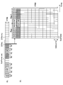
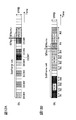
- FIG. 7 shows that six DCIs (DCI # 1- # 6) are set in the same subframe set, and transmission start timing of uplink data (PUSCH # 1- # 6) each scheduled with the six DCIs The case where control is performed so that (assignment start position) is the same is shown.
- UL data (PUSCH # 1- # 6) transmission scheduled in DCI # 1- # 6 is started from a predetermined subframe.
- the predetermined subframe may be a subframe (for example, SF # n + k 2 ) after a predetermined period from the last subframe (for example, SF # n) of the subframe set.
- k 2 can be an integer greater than zero (eg, 4).
- the radio base station includes different UL allocation information (for example, UL data resources (subcarriers)) included in the DCI (UL grant) included in the same subframe set, and transmits them to the user terminal.
- UL allocation information for example, UL data resources (subcarriers)
- the user terminal When receiving the DCI included in the subframe set, the user terminal starts UL data transmission from a predetermined subframe regardless of the subframe number or the like that received the DCI.
- the user terminal can determine the UL data allocation resource (subcarrier) based on the received DCI. Also, the user terminal determines the timing of the last subframe (SF # n) of the subframe set based on information (for example, information on the subframe set) notified by higher layer signaling and / or DCI. Can do. Note that the information regarding the timing of the last subframe of the subframe set may be the number of subframes constituting the subframe set, an offset specifying the position of the subframe set, and the like.
- FIG. 8 shows a case where two DCIs (DCI # 1, # 2) for applying repeated transmission (repetition number 4) to the same subframe set are set. Moreover, the case where it controls so that the transmission start timing of the uplink data (for example, PUSCH # 1, # 2) each scheduled by the said 2 DCI becomes the same is shown.
- control is performed so that transmission of UL data (PUSCH # 1, # 2) respectively scheduled by DCI # 1, # 2 is started from a predetermined subframe.
- the predetermined subframe may be a subframe (for example, SF # n + k 2 ) after a predetermined period from the last subframe (for example, SF # n) of the subframe set.
- k 2 can be a value greater than 0 (e.g., 4).
- the user terminal determines UL data allocation resources (subcarriers) based on the received DCI, and starts UL data transmission from a predetermined subframe.
- UL data allocation resources subcarriers
- a case is shown in which the user terminal performs single-tone transmission of UL data with a repetition number of 2. In this case, it is possible to suppress occurrence of unused resources between different uplink data. Note that the number of repeated transmissions applied to uplink data scheduled with different DCIs in the same subframe set may be the same or different.
- the predetermined subframe serving as the UL data transmission start timing is determined based on the last subframe of the subframe set.
- the present embodiment is not limited to this. Absent.
- the predetermined subframe may be determined based on the subframe in which the last DCI (downlink control channel) included in the subframe set is transmitted. As the last DCI, only DCI (UL grant) for scheduling UL transmission may be considered, or both DCI for scheduling UL transmission and DCI (DL assignment) for scheduling DL transmission may be considered. Also good.
- the UL transmission start timing is determined based on the subframe in which the last DCI (DCI # 6) is transmitted among the DCIs (DCI # 1- # 6) included in the subframe set. Show the case. Note that FIG. 9 shows a case where repeated transmission is not used (normal coverage case), and FIG. 10 shows a case where repeated transmission is applied (extended coverage case).
- the radio base station includes information on a subframe (SF # m) in which the last DCI (DCI # 6) included in the subframe set is transmitted in the DCI (eg, DCI # 1- # 6), and the user terminal Can be notified.
- the user terminal determines a subframe (for example, SF # m) in which DCI # 6 is transmitted based on information included in the DCI, and a subframe (for example, SF # m + k 2 ) after a predetermined period from the subframe. ) To start UL transmission.
- k 2 can be a value greater than 0 (e.g., 4).
- the radio base station may notify the user terminal by including information on a predetermined subframe serving as a UL transmission start timing in the DCI.
- the information on the predetermined subframe may be information for determining the predetermined subframe, and may be, for example, the number of the predetermined subframe itself or a subframe serving as a reference for determining the predetermined subframe.
- the radio base station can transmit to each user terminal including information on a predetermined subframe in each DCI transmitted in the same subframe set.
- reception start timing of downlink data scheduled by DCI included in a subframe set is controlled.
- a case where downlink data is transmitted with multitone (a plurality of subcarriers (for example, 1 PRB)) is shown, but the present invention can also be applied to a case of transmitting with single tone (single subcarrier). it can.
- FIG. 11A shows a case where seven DCIs (DCI # 1- # 7) are set in the subframe set.
- uplink data is scheduled with six DCIs (DCI # 1- # 6) and downlink data is scheduled with one DCI (DCI # 7). That is, DCI # 1- # 6 corresponds to UL grant, and DCI # 7 corresponds to DL assignment.
- DCI # 1- # 6 corresponds to UL grant
- DCI # 7 corresponds to DL assignment. Note that the number of DCI for downlink scheduling and the number of DCI for uplink scheduling are not limited to this.
- the user terminal starts receiving DL data (PDSCH) scheduled in DCI # 7 from a predetermined subframe.
- the predetermined subframe may be a subframe (for example, SF # n + k 1 ) after a predetermined period from the last subframe (for example, SF # n) of the subframe set.
- k 1 may be an integer greater than 0 (eg, 1).
- the first mode described above can be applied to UL data (PUSCH # 1- # 6) transmissions scheduled in DCI # 1- # 6, respectively.
- the radio base station includes DL allocation information (for example, DL data resource (subcarrier)) included in the DCI (DL assignment) included in the subframe set, and transmits it to the user terminal.
- the user terminal receives DL data from a predetermined subframe regardless of the subframe number that received the DCI.
- the user terminal can determine the DL data allocation resource (subcarrier) based on the received DCI. Also, the user terminal determines the timing of the last subframe (SF # n) of the subframe set based on information (for example, information on the subframe set) notified by higher layer signaling and / or DCI. Can do.
- FIG. 11B shows a case where two DCIs (DCI # 1, # 2) that apply repeated transmission (repetition number 4) to the same subframe set are set.
- DCI # 1 corresponds to a DL assignment
- DCI # 2 corresponds to a UL grant.
- the user terminal starts reception of DL data (PDSCH) scheduled by DCI # 1 from a predetermined subframe.
- the predetermined subframe may be a subframe (for example, SF # n + k 1 ) after a predetermined period from the last subframe (for example, SF # n) of the subframe set.
- the reception start timing of DL data scheduled by DCI included in a subframe set is not the reception timing (reception subframe) of the DCI but the last subframe constituting the subframe set. Determine based on frame.
- FIG. 11 shows the case where the predetermined subframe serving as the DL data reception start timing is determined based on the last subframe of the subframe set
- the present embodiment is not limited to this.
- the predetermined subframe may be determined based on the subframe in which the last DCI (downlink control channel) included in the subframe set is transmitted.
- 12A and 12B in the subframe in which the last DCI (DCI # 6 / DCI # 2) is transmitted among the DCIs (DCI # 1- # 7 / DCI # 1, # 2) included in the subframe set.
- the case where DL reception start timing is determined based on this is shown.
- 12A shows a case where repeated transmission is not used (normal coverage case)
- FIG. 12B shows a case where repeated transmission is applied (extended coverage case).
- the radio base station includes information on the subframe (SF # m) in which the last DCI included in the subframe set is transmitted in the DCI (for example, DCI # 1- # 6 in FIG. 12A) to the user terminal. You can be notified. Based on information included in the DCI, the user terminal determines a subframe (for example, SF # m) in which the last DCI is transmitted, and a subframe (for example, SF # m + k 1 ) after a predetermined period from the subframe. ) To start UL transmission.
- k 1 may be a value greater than 0 (e.g., 1).
- the reception start timing of DL data scheduled by DCI included in the subframe set it is possible to suppress collision between DCI included in the subframe set and DL data.
- the allocation start position of DL data scheduled in each DL assignment can be made the same. Thereby, generation
- the DL data reception (DL allocation) start timing can be advanced compared to FIG. it can. As a result, resource utilization efficiency can be further improved, and delay can be reduced.
- the radio base station may notify the user terminal by including information on a predetermined subframe serving as a DL transmission start timing in the DCI.
- the information on the predetermined subframe may be information for determining the predetermined subframe, and may be, for example, the number of the predetermined subframe itself or a subframe serving as a reference for determining the predetermined subframe.
- the radio base station can transmit to each user terminal including information on a predetermined subframe in each DCI transmitted in the same subframe set.
- wireless communication system a configuration of a wireless communication system according to an embodiment of the present invention will be described.
- the wireless communication method according to each aspect described above is applied.
- wireless communication method which concerns on each aspect may be used independently, and may be combined.
- an NB-IoT terminal is exemplified as a user terminal whose use band is limited to a narrow band, but the present invention is not limited to this.
- FIG. 13 is a schematic configuration diagram of a radio communication system according to an embodiment of the present invention.
- a wireless communication system 1 illustrated in FIG. 13 is an example in which an LTE system is employed in a network domain of a machine communication system.
- carrier aggregation (CA) and / or dual connectivity (DC) in which a plurality of basic frequency blocks (component carriers) having the system bandwidth of the LTE system as one unit can be applied.
- CA carrier aggregation
- DC dual connectivity
- the LTE system is set to a system band from a minimum of 1.4 MHz to a maximum of 20 MHz for both the downlink and the uplink, the configuration is not limited to this.
- the wireless communication system 1 includes SUPER 3G, LTE-A (LTE-Advanced), IMT-Advanced, 4G (4th generation mobile communication system), 5G (5th generation mobile communication system), FRA (Future Radio Access), etc. May be called.
- the wireless communication system 1 includes a wireless base station 10 and a plurality of user terminals 20A, 20B, and 20C that are wirelessly connected to the wireless base station 10.
- the radio base station 10 is connected to the higher station apparatus 30 and is connected to the core network 40 via the higher station apparatus 30.
- the upper station device 30 includes, for example, an access gateway device, a radio network controller (RNC), a mobility management entity (MME), and the like, but is not limited thereto.
- a plurality of user terminals 20 (20A-20C) can communicate with the radio base station 10 in the cell 50.
- the user terminal 20A is a user terminal that supports LTE (up to Rel-10) or LTE-Advanced (including Rel-10 and later) (hereinafter, LTE terminal (LTE UE: LTE User Equipment)), and other terminals.
- LTE terminal LTE UE: LTE User Equipment
- the user terminals 20B and 20C are NB-IoT terminals (NB-IoT UE (NB-IoT User Equipment)) serving as communication devices in the machine communication system.
- NB-IoT UE NB-IoT User Equipment
- the user terminals 20 ⁇ / b> A, 20 ⁇ / b> B, and 20 ⁇ / b> C are simply referred to as the user terminal 20 unless it is necessary to distinguish between them.
- the user terminal 20 may be called a UE (User Equipment) or the like.
- the NB-IoT terminals 20B and 20C are user terminals whose use band is limited to a narrower band than the minimum system bandwidth supported by the existing LTE system.
- the NB-IoT terminals 20B and 20C may be terminals compatible with various communication methods such as LTE and LTE-A, and are not limited to fixed communication terminals such as electric meters, gas meters, and vending machines, but also vehicles and the like.
- the mobile communication terminal may be used.
- the user terminal 20 may communicate directly with another user terminal 20 or may communicate via the radio base station 10.
- orthogonal frequency division multiple access (OFDMA) is applied to the downlink, and single carrier-frequency division multiple access (SC-FDMA: Single-) is applied to the uplink.
- Carrier Frequency Division Multiple Access is applied.
- OFDMA is a multi-carrier transmission scheme that performs communication by dividing a frequency band into a plurality of narrow frequency bands (subcarriers) and mapping data to each subcarrier.
- SC-FDMA is a single-carrier transmission scheme that reduces interference between terminals by dividing the system bandwidth into bands consisting of one or continuous resource blocks for each terminal, and using a plurality of bands different from each other. is there.
- the uplink and downlink radio access methods are not limited to these combinations.
- downlink channels include a downlink shared channel (PDSCH) shared by each user terminal 20, a broadcast channel (PBCH: Physical Broadcast Channel), a downlink L1 / L2 control channel, and the like. Used. User data, higher layer control information, and predetermined SIB (System Information Block) are transmitted by PDSCH. Also, MIB (Master Information Block) is transmitted by PBCH.
- PDSCH downlink shared channel
- PBCH Physical Broadcast Channel
- SIB System Information Block
- Downlink L1 / L2 control channels include PDCCH (Physical Downlink Control Channel), EPDCCH (Enhanced Physical Downlink Control Channel), PCFICH (Physical Control Format Indicator Channel), PHICH (Physical Hybrid-ARQ Indicator Channel), and the like.
- Downlink control information (DCI: Downlink Control Information) including scheduling information of PDSCH and PUSCH is transmitted by PDCCH.
- the number of OFDM symbols used for PDCCH is transmitted by PCFICH.
- the retransmission control information (HARQ-ACK) of PUSCH is transmitted by PHICH.
- the EPDCCH is frequency-division multiplexed with the PDSCH, and is used for transmission of DCI and the like as with the PDCCH.
- an uplink shared channel (PUSCH: Physical Uplink Shared Channel) shared by each user terminal 20, an uplink L1 / L2 control channel (PUCCH: Physical Uplink Control Channel), a random access channel (PRACH: Physical Random Access Channel) is used.
- PUSCH may be referred to as an uplink data channel.
- User data and higher layer control information are transmitted by PUSCH.
- downlink radio quality information (CQI: Channel Quality Indicator), retransmission control information (HARQ-ACK), and the like are transmitted by PUCCH.
- CQI Channel Quality Indicator
- HARQ-ACK retransmission control information
- a random access preamble for establishing connection with a cell is transmitted by the PRACH.
- the channel for the MTC terminal / NB-IoT terminal may be represented with “M” indicating MTC or “NB” indicating NB-IoT, and may be represented by PDCCH / for MTC terminal / NB-IoT terminal.
- EPDCCH, PDSCH, PUCCH, PUSCH may be referred to as M (NB) -PDCCH, M (NB) -PDSCH, M (NB) -PUCCH, M (NB) -PUSCH, etc., respectively.
- PDCCH, PDSCH, PUCCH, and PUSCH are simply referred to as PDCCH, PDSCH, PUCCH, and PUSCH.
- a cell-specific reference signal CRS
- CSI-RS channel state information reference signal
- DMRS demodulation reference signal
- PRS Positioning Reference Signal
- a measurement reference signal SRS: Sounding Reference Signal
- a demodulation reference signal DMRS
- the DMRS may be referred to as a user terminal specific reference signal (UE-specific Reference Signal). Further, the transmitted reference signal is not limited to these.
- FIG. 14 is a diagram illustrating an example of an overall configuration of a radio base station according to an embodiment of the present invention.
- the radio base station 10 includes at least a plurality of transmission / reception antennas 101, an amplifier unit 102, a transmission / reception unit 103, a baseband signal processing unit 104, a call processing unit 105, and a transmission path interface 106.
- User data transmitted from the radio base station 10 to the user terminal 20 via the downlink is input from the higher station apparatus 30 to the baseband signal processing unit 104 via the transmission path interface 106.
- PDCP Packet Data Convergence Protocol
- RLC Radio Link Control
- MAC Medium Access
- Retransmission control for example, HARQ (Hybrid Automatic Repeat reQuest) transmission processing
- HARQ Hybrid Automatic Repeat reQuest
- the downlink control signal is also subjected to transmission processing such as channel coding and inverse fast Fourier transform, and transferred to each transmitting / receiving unit 103.
- Each transmission / reception unit 103 converts the baseband signal output by precoding from the baseband signal processing unit 104 for each antenna to a radio frequency band and transmits the converted signal.
- the transmission / reception unit 103 can be configured by a transmitter / receiver, a transmission / reception circuit, or a transmission / reception device, which is described based on common recognition in the technical field according to the present invention.
- the transmission / reception part 103 may be comprised as an integral transmission / reception part, and may be comprised from a transmission part and a receiving part.
- the radio frequency signal frequency-converted by the transmission / reception unit 103 is amplified by the amplifier unit 102 and transmitted from the transmission / reception antenna 101.
- the transmission / reception unit 103 can transmit and receive various signals with a narrow bandwidth (for example, 180 kHz) limited by the system bandwidth (for example, one component carrier).
- the radio frequency signal received by each transmitting / receiving antenna 101 is amplified by the amplifier unit 102.
- Each transmitting / receiving unit 103 receives the upstream signal amplified by the amplifier unit 102.
- the transmission / reception unit 103 converts the frequency of the received signal into a baseband signal and outputs it to the baseband signal processing unit 104.
- the baseband signal processing unit 104 performs fast Fourier transform (FFT) processing, inverse discrete Fourier transform (IDFT: Inverse Discrete Fourier Transform) processing, and error correction on user data included in the input upstream signal.
- FFT fast Fourier transform
- IDFT inverse discrete Fourier transform
- Decoding, MAC retransmission control reception processing, RLC layer, and PDCP layer reception processing are performed and transferred to the upper station apparatus 30 via the transmission path interface 106.
- the call processing unit 105 performs call processing such as communication channel setting and release, state management of the radio base station 10, and radio resource management.
- the transmission path interface 106 transmits and receives signals to and from the higher station apparatus 30 via a predetermined interface.
- the transmission path interface 106 transmits / receives signals (backhaul signaling) to / from other radio base stations 10 via an interface between base stations (for example, an optical fiber compliant with CPRI (Common Public Radio Interface), X2 interface). May be.
- CPRI Common Public Radio Interface
- X2 interface May be.
- the transmission / reception unit (transmission unit) 103 transmits downlink control information using a subframe set set for a downlink control channel in a predetermined bandwidth.
- the transmission / reception unit (reception unit) 103 receives uplink data transmitted from the user terminal based on the downlink control information. Further, the transmission / reception unit (reception unit) 103 can start reception of uplink data scheduled with downlink control information transmitted in the same subframe set from a predetermined subframe.
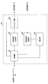
- FIG. 15 is a diagram illustrating an example of a functional configuration of the radio base station according to the embodiment of the present invention. Note that FIG. 15 mainly shows functional blocks of characteristic portions in the present embodiment, and the radio base station 10 also has other functional blocks necessary for radio communication. As illustrated in FIG. 15, the baseband signal processing unit 104 includes at least a control unit 301, a transmission signal generation unit (generation unit) 302, a mapping unit 303, a reception signal processing unit 304, and a measurement unit 305. I have.
- the control unit 301 controls the entire radio base station 10.
- the control part 301 can be comprised from the controller, the control circuit, or control apparatus demonstrated based on the common recognition in the technical field which concerns on this invention.
- the control unit 301 controls signal generation by the transmission signal generation unit 302 and signal allocation by the mapping unit 303, for example.
- the control unit 301 also controls signal reception processing by the reception signal processing unit 304 and signal measurement by the measurement unit 305.
- the control unit 301 also controls system information, PDSCH, and PUSCH resource allocation (scheduling). It also controls resource allocation for downlink signals such as synchronization signals (for example, PSS (Primary Synchronization Signal) / SSS (Secondary Synchronization Signal), NB-SS) and CRS, CSI-RS, DM-RS.
- control unit 301 controls the transmission signal generation unit 302 and the mapping unit 303 so that various signals are allocated to a narrow band and transmitted to the user terminal 20.
- the control unit 301 controls, for example, downlink broadcast information (MIB, SIB (MTC-SIB)), PDCCH (also referred to as M-PDCCH, NB-PDCCH, etc.), PDSCH, and the like in a narrow band.
- the narrow band (NB) is a band (for example, 180 kHz) narrower than the system band of the existing LTE system.
- control unit 301 receives the PUSCH with the determined PUSCH resource in cooperation with the transmission / reception unit 103, the reception signal processing unit 302, and the measurement unit 305. Further, the control unit 301 cooperates with the transmission signal generation unit 302, the mapping unit 303, and the transmission / reception unit 103 to transmit the PDSCH using the determined PDSCH resource.
- the transmission signal generation unit (generation unit) 302 generates a downlink signal (PDCCH, PDSCH, downlink reference signal, etc.) based on an instruction from the control unit 301 and outputs it to the mapping unit 303.
- the transmission signal generation unit 302 can be configured by a signal generator, a signal generation circuit, or a signal generation device described based on common recognition in the technical field according to the present invention.
- the transmission signal generation unit 302 generates, for example, DCI (also referred to as DL assignment, UL grant, etc.) that allocates the PUSCH and / or PDSCH to the user terminal 20 based on an instruction from the control unit 301.
- DCI also referred to as DL assignment, UL grant, etc.
- the PDSCH is subjected to coding processing and modulation processing according to a coding rate, a modulation scheme, and the like determined based on channel state information (CSI) from each user terminal 20.
- CSI channel state information
- the mapping unit 303 Based on an instruction from the control unit 301, the mapping unit 303 maps the downlink signal generated by the transmission signal generation unit 302 to a predetermined narrowband radio resource (for example, a maximum of one resource block), and transmits and receives To 103.
- the mapping unit 303 can be configured by a mapper, a mapping circuit, or a mapping device described based on common recognition in the technical field according to the present invention.
- the reception signal processing unit 304 performs reception processing (for example, demapping, demodulation, decoding, etc.) on the reception signal input from the transmission / reception unit 103.
- the received signal is, for example, an uplink signal (PUCCH, PUSCH, uplink reference signal, etc.) transmitted from the user terminal 20.
- the reception signal processing unit 304 can be configured by a signal processor, a signal processing circuit, or a signal processing device described based on common recognition in the technical field according to the present invention.
- the reception signal processing unit 304 outputs the information decoded by the reception processing to the control unit 301.
- the reception signal processing unit 304 outputs the reception signal and the signal after reception processing to the measurement unit 305.
- the measurement unit 305 performs measurement on the received signal.
- the measurement part 305 can be comprised from the measuring device, measurement circuit, or measurement apparatus demonstrated based on common recognition in the technical field which concerns on this invention.
- the measurement unit 305 may measure signal reception power (for example, RSRP (Reference Signal Received Power)), reception quality (for example, RSRQ (Reference Signal Received Quality)), channel state, and the like.
- the measurement result may be output to the control unit 301.
- FIG. 16 is a diagram illustrating an example of an overall configuration of a user terminal according to an embodiment of the present invention. Although a detailed description is omitted here, a normal LTE terminal may behave as an NB-IoT terminal.
- the user terminal 20 includes at least a transmission / reception antenna 201, an amplifier unit 202, a transmission / reception unit 203, a baseband signal processing unit 204, and an application unit 205.
- the user terminal 20 may include a plurality of transmission / reception antennas 201, an amplifier unit 202, a transmission / reception unit 203, and the like.
- the radio frequency signal received by the transmission / reception antenna 201 is amplified by the amplifier unit 202.
- the transmission / reception unit 203 receives the downlink signal amplified by the amplifier unit 202.
- the transmission / reception unit 203 converts the frequency of the received signal into a baseband signal and outputs it to the baseband signal processing unit 204.
- the transmission / reception unit 203 can be configured by a transmitter / receiver, a transmission / reception circuit, or a transmission / reception device described based on common recognition in the technical field according to the present invention.
- the transmission / reception unit 203 may be configured as an integral transmission / reception unit, or may be configured from a transmission unit and a reception unit.
- the baseband signal processing unit 204 performs FFT processing, error correction decoding, retransmission control reception processing, and the like on the input baseband signal.
- the downlink user data is transferred to the application unit 205.
- the application unit 205 performs processing related to layers higher than the physical layer and the MAC layer.
- broadcast information in the downlink data is also transferred to the application unit 205.
- uplink user data is input from the application unit 205 to the baseband signal processing unit 204.
- retransmission control information HARQ-ACK
- channel coding channel coding
- precoding precoding
- DFT discrete Fourier transform
- IFFT processing IFFT processing
- the transmission / reception unit 203 converts the baseband signal output from the baseband signal processing unit 204 into a radio frequency band and transmits it.
- the radio frequency signal frequency-converted by the transmission / reception unit 203 is amplified by the amplifier unit 202 and transmitted from the transmission / reception antenna 201.
- the transmission / reception unit (reception unit) 203 receives downlink control information included in a subframe set set for a downlink control channel in a predetermined bandwidth. Further, the transmission / reception unit (reception unit) 203 can receive downlink control information including information on the last subframe to which the downlink control channel is assigned in the subframe set. Further, the transmission / reception unit (reception unit) 203 can receive information on the subframe set.
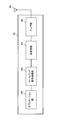
- FIG. 17 is a diagram illustrating an example of a functional configuration of the user terminal according to the embodiment of the present invention. Note that FIG. 17 mainly shows functional blocks of characteristic portions in the present embodiment, and the user terminal 20 also has other functional blocks necessary for wireless communication. As shown in FIG. 17, the baseband signal processing unit 204 included in the user terminal 20 includes a control unit 401, a transmission signal generation unit (generation unit) 402, a mapping unit 403, a reception signal processing unit 404, and a measurement unit. 405.
- the control unit 401 controls the entire user terminal 20.
- the control unit 401 can be composed of a controller, a control circuit, or a control device described based on common recognition in the technical field according to the present invention.
- the control unit 401 controls, for example, signal generation by the transmission signal generation unit 402 and signal allocation by the mapping unit 403.
- the control unit 401 controls signal reception processing by the reception signal processing unit 404 and signal measurement by the measurement unit 405.
- the control unit 401 acquires the downlink signal (PDCCH, PDSCH, downlink reference signal) transmitted from the radio base station 10 from the reception signal processing unit 404.
- the control unit 401 controls generation of uplink control information (UCI) such as retransmission control information (HARQ-ACK) and channel state information (CSI) and uplink data based on the downlink signal.
- UCI uplink control information
- HARQ-ACK retransmission control information
- CSI channel state information
- control unit 401 controls uplink data transmission based on downlink control information.
- control unit 401 can perform control so that uplink data transmission scheduled with downlink control information included in the same subframe set starts from a predetermined subframe.
- control unit 401 can start uplink data transmission scheduled with downlink control information included in the same subframe set from a subframe after a predetermined period from the last subframe of the subframe set ( (See FIGS. 7 and 8).
- control unit 401 starts uplink data transmission scheduled with downlink control information included in the same subframe set from a subframe after a predetermined period from the last subframe to which a downlink control channel is assigned in the subframe set. (See FIGS. 9 and 10).
- control unit 401 can repeatedly transmit uplink data transmission scheduled with downlink control information included in the same subframe set from a predetermined subframe.
- control unit 401 can perform control so that uplink data transmission scheduled with downlink control information included in the same subframe set is transmitted using a single carrier. Note that uplink data scheduled for downlink control information included in a subframe set can be assigned to different subcarriers in the same PRB.
- control unit 401 can control downlink data reception scheduled with downlink control information included in the subframe set so as to start from a predetermined subframe (see FIGS. 11 and 12).
- control unit 401 cooperates with the transmission signal generation unit 402, the mapping unit 403, and the transmission / reception unit 203 to transmit PUSCH using the PUSCH resource.
- control unit 401 receives the PDSCH using the PDSCH resource in cooperation with the transmission / reception unit 203, the reception signal processing unit 404, and the measurement unit 405.
- the transmission signal generation unit 402 generates an uplink signal (PUCCH, PUSCH, uplink reference signal, etc.) based on an instruction from the control unit 401 and outputs the uplink signal to the mapping unit 403.
- the transmission signal generation unit 402 can be configured by a signal generator, a signal generation circuit, or a signal generation device described based on common recognition in the technical field according to the present invention.
- the transmission signal generation unit 402 generates uplink control information (UCI) and / or uplink data based on an instruction from the control unit 401, for example. Also, the transmission signal generation unit 402 generates a PUSCH that transmits UCI and / or uplink data based on an instruction from the control unit 401. For example, the transmission signal generation unit 402 is instructed by the control unit 401 to generate a PUSCH when DCI that assigns a PUSCH to the user terminal 20 is received. Further, the transmission signal generation unit 402 generates a PUCCH that transmits UCI based on an instruction from the control unit 401.
- UCI uplink control information
- PUSCH that transmits UCI and / or uplink data based on an instruction from the control unit 401. For example, the transmission signal generation unit 402 is instructed by the control unit 401 to generate a PUSCH when DCI that assigns a PUSCH to the user terminal 20 is received. Further, the transmission signal generation unit 402 generates a PUCCH that
- the mapping unit 403 maps the uplink signal generated by the transmission signal generation unit 402 to a resource (for example, a PUSCH resource or a PUCCH resource) based on an instruction from the control unit 401, and outputs the resource to the transmission / reception unit 203.
- the mapping unit 403 can be configured by a mapper, a mapping circuit, or a mapping device described based on common recognition in the technical field according to the present invention.
- the reception signal processing unit 404 performs reception processing (for example, demapping, demodulation, decoding, etc.) on the reception signal input from the transmission / reception unit 203.
- the received signal is, for example, a downlink signal (downlink control signal, downlink data signal, downlink reference signal, etc.) transmitted from the radio base station 10.
- the reception signal processing unit 404 can be configured by a signal processor, a signal processing circuit, or a signal processing device described based on common recognition in the technical field according to the present invention.
- the reception signal processing unit 404 outputs the information decoded by the reception processing to the control unit 401.
- the reception signal processing unit 404 outputs broadcast information, system information, RRC signaling, DCI, and the like to the control unit 401, for example.
- the reception signal processing unit 404 outputs the reception signal and the signal after reception processing to the measurement unit 405.
- the measurement unit 405 performs measurement on the received signal.
- the measurement part 405 can be comprised from the measuring device, measurement circuit, or measurement apparatus demonstrated based on common recognition in the technical field which concerns on this invention.
- the measurement unit 405 may measure, for example, the received power (for example, RSRP), reception quality (for example, RSRQ), channel state, and the like of the received signal.
- the measurement result may be output to the control unit 401.
- each functional block is realized by one physically coupled device, or may be realized by two or more physically separated devices connected by wire or wirelessly and by a plurality of these devices. Good.
- a wireless base station, a user terminal, etc. in an embodiment of the present invention may function as a computer that performs processing of the wireless communication method of the present invention.
- FIG. 18 is a diagram illustrating an example of a hardware configuration of a radio base station and a user terminal according to an embodiment of the present invention.
- the wireless base station 10 and the user terminal 20 described above may be physically configured as a computer device including a processor 1001, a memory 1002, a storage 1003, a communication device 1004, an input device 1005, an output device 1006, a bus 1007, and the like. Good.
- the term “apparatus” can be read as a circuit, a device, a unit, or the like.
- the hardware configurations of the radio base station 10 and the user terminal 20 may be configured to include one or a plurality of each device illustrated in the figure, or may be configured not to include some devices.
- Each function in the radio base station 10 and the user terminal 20 is obtained by reading predetermined software (program) on hardware such as the processor 1001 and the memory 1002, so that the processor 1001 performs computation, and communication by the communication device 1004, This is realized by controlling reading and / or writing of data in the memory 1002 and the storage 1003.
- the processor 1001 controls the entire computer by operating an operating system, for example.
- the processor 1001 may be configured by a central processing unit (CPU) including an interface with peripheral devices, a control device, an arithmetic device, a register, and the like.
- CPU central processing unit
- the baseband signal processing unit 104 (204) and the call processing unit 105 described above may be realized by the processor 1001.
- the processor 1001 reads programs (program codes), software modules, and data from the storage 1003 and / or the communication device 1004 to the memory 1002, and executes various processes according to these.
- programs program codes
- software modules software modules
- data data from the storage 1003 and / or the communication device 1004 to the memory 1002, and executes various processes according to these.
- the program a program that causes a computer to execute at least a part of the operations described in the above embodiments is used.
- the control unit 401 of the user terminal 20 may be realized by a control program stored in the memory 1002 and operated by the processor 1001, and may be realized similarly for other functional blocks.
- the memory 1002 is a computer-readable recording medium, and may be configured by at least one of ROM (Read Only Memory), EPROM (Erasable Programmable ROM), RAM (Random Access Memory), and the like, for example.
- the memory 1002 may be called a register, a cache, a main memory (main storage device), or the like.
- the memory 1002 can store a program (program code), a software module, and the like that can be executed to implement the wireless communication method according to the embodiment of the present invention.
- the storage 1003 is a computer-readable recording medium, and may be composed of at least one of an optical disk such as a CD-ROM (Compact Disc ROM), a hard disk drive, a flexible disk, a magneto-optical disk, and a flash memory, for example. .
- the storage 1003 may be referred to as an auxiliary storage device.
- the communication device 1004 is hardware (transmission / reception device) for performing communication between computers via a wired and / or wireless network, and is also referred to as a network device, a network controller, a network card, a communication module, or the like.
- a network device for example, the transmission / reception antenna 101 (201), the amplifier unit 102 (202), the transmission / reception unit 103 (203), the transmission path interface 106, and the like described above may be realized by the communication device 1004.
- the input device 1005 is an input device (for example, a keyboard, a mouse, etc.) that accepts external input.
- the output device 1006 is an output device (for example, a display, a speaker, etc.) that performs output to the outside.
- the input device 1005 and the output device 1006 may have an integrated configuration (for example, a touch panel).
- each device such as the processor 1001 and the memory 1002 is connected by a bus 1007 for communicating information.
- the bus 1007 may be configured with a single bus or may be configured with different buses between apparatuses.
- the radio base station 10 and the user terminal 20 include a microprocessor, a digital signal processor (DSP), an ASIC (Application Specific Integrated Circuit), a PLD (Programmable Logic Device), an FPGA (Field Programmable Gate Array), and the like. It may be configured including hardware, and a part or all of each functional block may be realized by the hardware. For example, the processor 1001 may be implemented by at least one of these hardware.
- DSP digital signal processor
- ASIC Application Specific Integrated Circuit
- PLD Programmable Logic Device
- FPGA Field Programmable Gate Array
- the channel and / or symbol may be a signal (signaling).
- the signal may be a message.
- a component carrier CC may be called a cell, a frequency carrier, a carrier frequency, or the like.
- the radio frame may be configured with one or a plurality of periods (frames) in the time domain.
- Each of the one or more periods (frames) constituting the radio frame may be referred to as a subframe.
- a subframe may be composed of one or more slots in the time domain.
- a slot may be composed of one or more symbols (OFDM symbols, SC-FDMA symbols, etc.) in the time domain.
- the radio frame, subframe, slot, and symbol all represent a time unit when transmitting a signal.
- Different names may be used for the radio frame, the subframe, the slot, and the symbol.
- one subframe may be referred to as a transmission time interval (TTI)
- a plurality of consecutive subframes may be referred to as a TTI
- one slot may be referred to as a TTI.
- the subframe or TTI may be a subframe (1 ms) in the existing LTE, a period shorter than 1 ms (for example, 1-13 symbols), or a period longer than 1 ms. Also good.
- TTI means, for example, a minimum time unit for scheduling in wireless communication.
- a radio base station performs scheduling to allocate radio resources (frequency bandwidth, transmission power, etc. that can be used in each user terminal) to each user terminal in units of TTI.
- the definition of TTI is not limited to this.
- a TTI having a time length of 1 ms may be called a normal TTI (TTI in LTE Rel. 8-12), a normal TTI, a long TTI, a normal subframe, a normal subframe, or a long subframe.
- TTI shorter than a normal TTI may be called a shortened TTI, a short TTI, a shortened subframe, a short subframe, or the like.
- a resource block is a resource allocation unit in the time domain and the frequency domain, and may include one or a plurality of continuous subcarriers (subcarriers) in the frequency domain. Further, the RB may include one or a plurality of symbols in the time domain, and may have a length of one slot, one subframe, or 1 TTI. One TTI and one subframe may each be composed of one or a plurality of resource blocks.
- the RB may be called a physical resource block (PRB: Physical RB), a PRB pair, an RB pair, or the like.
- the resource block may be composed of one or a plurality of resource elements (RE: Resource Element).
- RE Resource Element
- 1RE may be a radio resource region of 1 subcarrier and 1 symbol.
- the structure of the above-described radio frame, subframe, slot, symbol, and the like is merely an example.
- the configuration such as the cyclic prefix (CP) length can be variously changed.
- information, parameters, and the like described in this specification may be represented by absolute values, may be represented by relative values from a predetermined value, or may be represented by other corresponding information.
- the radio resource may be indicated by a predetermined index.
- software, instructions, information, etc. may be sent and received via a transmission medium.
- software may use websites, servers, or other devices using wired technology (coaxial cable, fiber optic cable, twisted pair and digital subscriber line (DSL), etc.) and / or wireless technology (infrared, microwave, etc.) When transmitted from a remote source, these wired and / or wireless technologies are included within the definition of transmission media.
- the radio base station in this specification may be read by the user terminal.
- each aspect / embodiment of the present invention may be applied to a configuration in which communication between a radio base station and a user terminal is replaced with communication between a plurality of user terminals (D2D: Device-to-Device).
- the user terminal 20 may have a function that the wireless base station 10 has.
- words such as “up” and “down” may be read as “side”.
- the uplink channel may be read as a side channel.
- a user terminal in this specification may be read by a radio base station.
- the wireless base station 10 may have a function that the user terminal 20 has.
- notification of predetermined information is not limited to explicitly performed, but is performed implicitly (for example, by not performing notification of the predetermined information). May be.
- notification of information is not limited to the aspect / embodiment described in this specification, and may be performed by other methods.
- notification of information includes physical layer signaling (eg, DCI (Downlink Control Information), UCI (Uplink Control Information)), upper layer signaling (eg, RRC (Radio Resource Control) signaling, broadcast information (MIB (Master Information Block)). ), SIB (System Information Block), etc.), MAC (Medium Access Control) signaling), other signals, or a combination thereof.
- the RRC signaling may be referred to as an RRC message, and may be, for example, an RRC connection setup (RRCConnectionSetup) message, an RRC connection reconfiguration (RRCConnectionReconfiguration) message, or the like.
- the MAC signaling may be notified by, for example, a MAC control element (MAC CE (Control Element)).
- MAC CE Control Element
- LTE Long Term Evolution
- LTE-A Long Term Evolution
- LTE-B Long Term Evolution-Beyond
- SUPER 3G IMT-Advanced
- 4G 4th generation.
- mobile communication system 5G (5th generation mobile communication system)
- FRA Full Radio Access
- New-RAT Radio Access Technology
- CDMA2000 Code Division Multiple Access 2000
- UMB User Mobile Broadband
- IEEE 802.11 Wi-Fi (registered trademark)
- IEEE 802.16 WiMAX (registered trademark)
- IEEE 802.20 UWB (Ultra-WideBand
- Bluetooth registered trademark
Landscapes
- Engineering & Computer Science (AREA)
- Signal Processing (AREA)
- Computer Networks & Wireless Communication (AREA)
- Mobile Radio Communication Systems (AREA)
Abstract
既存のLTEシステムにおけるリソース割り当て単位よりも小さい周波数単位(例えば、サブキャリア単位)で割当てが制御される場合であっても通信を適切に行うこと。所定の帯域幅において所定期間に含まれる下り制御チャネルで下り制御情報を受信する受信部と、前記下り制御情報に基づいて上りデータ送信を制御する制御部と、を有し、前記制御部は、前記所定期間において下り制御チャネルが最後に送信されるサブフレームを基準として上りデータ送信の開始タイミングを制御する。
Description
本発明は、次世代移動通信システムにおけるユーザ端末、無線基地局及び無線通信方法に関する。
UMTS(Universal Mobile Telecommunications System)ネットワークにおいて、さらなる高速データレート、低遅延などを目的としてロングタームエボリューション(LTE:Long Term Evolution)が仕様化された(非特許文献1)。また、LTEからの更なる広帯域化及び高速化を目的として、LTEの後継システム(例えば、LTE-A(LTE-Advanced)、FRA(Future Radio Access)、4G、5G、LTE Rel.13、14、15~、などともいう)も検討されている。
ところで、近年、通信装置の低コスト化に伴い、ネットワークに繋がれた装置が、人間の手を介さずに相互に通信して自動的に制御を行う機器間通信(M2M:Machine-to-Machine)の技術開発が盛んに行われている。特に、3GPP(Third Generation Partnership Project)は、M2Mの中でも機器間通信用のセルラシステムとして、MTC(Machine Type Communication)の最適化に関する標準化を進めている(非特許文献2)。MTC用ユーザ端末(MTC UE(User Equipment))は、例えば電気メータ、ガスメータ、自動販売機、車両、その他産業機器などの幅広い分野への利用が考えられている。
MTCでは、コストの低減及びセルラシステムにおけるカバレッジエリアの改善の観点から、簡易なハードウェア構成で実現可能なMTC用ユーザ端末(LC(Low-Cost)-MTC端末、LC-MTC UE)の需要が高まっている。このようなLC-MTC端末の通信方式として、非常に狭い帯域でのLTE通信(例えば、NB-IoT(Narrow Band Internet of Things)、NB-LTE(Narrow Band LTE)、NBセルラIoT(Narrow Band cellular Internet of Things)、クリーンスレート(clean slate)などと呼ばれてもよい)が検討されている。以降、本明細書で記載される「NB-IoT」は、上記NB-LTE、NBセルラIoT、クリーンスレートなど含むものとする。
NB-IoTをサポートするユーザ端末(以下、NB-IoT端末という)の使用帯域は、既存のLTEシステム(例えば、Rel.12以前のLTEシステム)の最小のシステム帯域(1.4MHz)よりも狭い帯域(例えば、180kHz、1リソースブロック(RB:Resource Block、PRB:Physical Resource Block等とも呼ばれる))に制限されることも想定される。
このように、既存のユーザ端末(例えば、Rel.12以前のLTE端末)と比較して使用帯域が狭帯域に制限されるNB-IoT端末に対しては、LTEシステムにおけるリソース割り当て単位であるPRBよりも小さい周波数単位(例えば、サブキャリア単位)でのリソース割り当てが必要となることが想定される。
しかしながら、既存のLTEシステムでは、ユーザ端末に対してPRB単位でのリソース割り当てが前提となっており、NB-IoT端末に対して、1PRBよりも小さい周波数単位でどのようにリソースを割り当てて通信を制御するかが問題となる。
本発明はかかる点に鑑みてなされたものであり、既存のLTEシステムにおけるリソース割り当て単位よりも小さい周波数単位(例えば、サブキャリア単位)で割当てが制御される場合であっても通信を適切に行うことができるユーザ端末、無線基地局及び無線通信方法を提供することを目的の一つとする。
本発明の一態様に係るユーザ端末は、所定の帯域幅において所定期間に含まれる下り制御チャネルで下り制御情報を受信する受信部と、前記下り制御情報に基づいて上りデータ送信を制御する制御部と、を有し、前記制御部は、前記所定期間において下り制御チャネルが最後に送信されるサブフレームを基準として上りデータ送信の開始タイミングを制御することを特徴とする。
本発明によれば、既存のLTEシステムにおけるリソース割り当て単位よりも小さい周波数単位(例えば、サブキャリア単位)で割当てが制御される場合であっても通信を適切に行うことができる。
NB-IoT端末では、処理能力の低下を許容して、ハードウェア構成を簡略化することが検討されている。例えば、NB-IoT端末では、既存のユーザ端末(例えば、Rel.12以前のLTE端末)に比べて、ピークレートの減少、トランスポートブロックサイズ(TBS:Transport Block Size)の制限、リソースブロック(RB:Resource Block、PRB:Physical Resource Block等とも呼ばれる)の制限、受信RF(Radio Frequency)の制限などを適用することが検討されている。
使用帯域の上限がシステム帯域(例えば、20MHz(100RB)、1コンポーネントキャリアなど)に設定されるLTE端末とは異なり、NB-IoT端末の使用帯域の上限は所定の狭帯域(NB:Narrow Band、例えば、180kHz、1.4MHz)に制限される。例えば、当該所定の狭帯域は、既存のLTEシステム(Rel.12以前のLTEシステム、以下、単に、LTEシステムともいう)の最小のシステム帯域(例えば、1.4MHz、6PRB)と同じ、又は、その一部の帯域(例えば、180kHz、1PRB)であってもよい。
このように、NB-IoT端末は、既存のLTE端末よりも使用帯域の上限が狭い端末、既存のLTE端末よりも狭い帯域(例えば、1.4MHzより狭い帯域)で送信及び/又は受信(以下、送受信という)可能な端末ともいえる。このNB-IoT端末は、既存のLTEシステムとの後方互換性を考慮してLTEシステムのシステム帯域内で動作させることが検討されている。例えば、LTEシステムのシステム帯域において、帯域が制限されたNB-IoT端末と帯域が制限されない既存のLTE端末との間で、周波数多重がサポートされてもよい。また、NB-IoTは、LTEシステム帯域内だけでなくLTEシステム帯域に隣接するキャリア間のガードバンドや専用周波数を用いて運用されても良い。
図1は、NB-IoT端末の使用帯域となる狭帯域の配置例を示す図である。図1では、NB-IoT端末の使用帯域がLTEシステムのシステム帯域(例えば、20MHz)の一部に設定されている。なお、図1以降では、NB-IoT端末の使用帯域が180kHzに設定されるものとするが、これに限られない。NB-IoT端末の使用帯域は、LTEシステムのシステム帯域(例えば、20MHz)より狭ければよく、例えば、Rel.13のLC-MTC端末の使用帯域(例えば、1.4MHz)以下であってもよい。
また、NB-IoT端末の使用帯域となる狭帯域の周波数位置は、システム帯域内で変化可能な構成とすることが好ましい。例えば、NB-IoT端末は、所定の期間(例えば、サブフレーム)毎に異なる周波数リソースを用いて通信することが好ましい。これにより、NB-IoT端末に対するトラヒックオフロードや、周波数ダイバーシチ効果が実現でき、周波数利用効率の低下を抑制することができる。したがって、NB-IoT端末は、周波数ホッピングや周波数スケジューリングの適用を考慮して、RFの再調整(retuning)機能を有することが好ましい。
また、NB-IoT端末は、下りと上りとで異なる帯域を使用してもよいし、同じ帯域を使用してもよい。下り送受信に使用される帯域は、下り狭帯域(DL NB:Downlink Narrow Band)と呼ばれてもよい。上り送受信に使用される帯域は、上り狭帯域(UL NB:Uplink Narrow Band)と呼ばれてもよい。
また、NB-IoT端末は、狭帯域に配置(allocate)される下り制御チャネルを用いて下り制御情報(DCI:Downlink Control Information)を受信する。当該下り制御チャネルは、PDCCH(Physical Downlink Control Channel)と呼ばれてもよいし、EPDCCH(Enhanced Physical Downlink Control Channel)と呼ばれてもよいし、M-PDCCH(MTC PDCCH)、NB-PDCCH等と呼ばれてもよい。
また、NB-IoT端末は、狭帯域に配置される下り共有チャネルを用いて下りデータを受信する。当該下り共有チャネルは、PDSCH(Physical Downlink Shared Channel)と呼ばれてもよいし、M-PDSCH(MTC PDSCH)と呼ばれてもよいし、NB-PDSCH等と呼ばれてもよい。
また、NB-IoT端末は、狭帯域に配置される上り制御チャネルを用いて、再送制御情報(HARQ-ACK:Hybrid Automatic Repeat reQuest-ACKnowledge)、チャネル状態情報(CSI:Channel State Information)などの上り制御情報(UCI:Uplink Control Information)を送信する。当該上り制御チャネルは、PUCCH(Physical Uplink Control Channel)と呼ばれてもよいし、M-PUCCH(MTC PUCCH)、NB-PUCCH等と呼ばれてもよい。
また、NB-IoT端末は、狭帯域に配置される上り共有チャネルを用いて、UCI及び/又は上りデータを受信する。当該上り共有チャネルは、PUSCH(Physical Uplink Shared Channel)と呼ばれてもよいし、M-PUSCH(MTC PUSCH)、NB-PUSCH等と呼ばれてもよい。
以上のチャネルに限られず、同じ用途に用いられる従来のチャネルにMTCを示す「M」やNB-IoTを示す「N」、または「NB」を付して表されてもよい。以下では、上記狭帯域で用いられる下り制御チャネル、下り共有チャネル、上り共有チャネル、上り共有チャネルを、それぞれ、PDCCH、PDSCH、PUCCH、PUSCHと呼ぶが、上述の通り、呼称はこれらに限られない。
また、NB-IoTでは、カバレッジを拡張するために、複数のサブフレームに渡って同一の下り信号(例えば、PDCCH、PDSCHなど)及び/又は上り信号(例えば、PUCCH、PUSCHなど)を送受信する繰り返し送信/受信が行われてもよい。同一の下り信号及び/又は上り信号が送受信される複数のサブフレーム数は、繰り返し数(repetition number)とも呼ばれる。また、当該繰り返し数は、繰り返しレベルによって示されてもよい。当該繰り返しレベルは、カバレッジ拡張(CE:Coverage Enhancement)レベルと呼ばれてもよい。
以上のようなNB-IoTでは、上り送信において、単一のトーンを用いた送信(シングルトーン送信(single-tone transmission))と複数のトーンを用いた送信(マルチトーン送信(multiple-tone transmission))とをサポートすることが検討されている。ここで、トーンとは、サブキャリアと同義であり、使用帯域(例えば、180kHz、1リソースブロック)が分割された各帯域を意味する。
シングルトーン送信では、既存のLTEシステムと同一のサブキャリア間隔(すなわち、15kHz)と、LTEシステムよりも狭いサブキャリア間隔(例えば、3.75kHz)とをサポートすることが検討されている。一方、マルチトーン送信では、LTEシステムと同一のサブキャリア間隔(すなわち、15kHz)をサポートすることが検討されている。サブキャリア間隔が15kHzの場合、1PRB(180kHz)が12サブキャリアで構成される。また、サブキャリア間隔が3.75kHzの場合、1PRBは、48サブキャリアで構成される。もちろん、本実施の形態で適用可能なサブキャリア間隔はこれらに限られない。
また、NB-IoT端末は、無線基地局から通知されたトーン(サブキャリア)数で、上り送信(例えば、PUSCH又は/及びPUCCHの送信)を行うことが検討されている。当該トーン数の組み合わせとしては、例えば、{1、3、6、12}等が考えられる。このように、予め定められた組み合わせの中から選択されたトーン数が、上位レイヤシグナリング(例えば、RRC(Radio Resource Control)シグナリングや報知情報)により設定(configure)され、NB-IoT端末は、設定されたトーン数で上り送信を行ってもよい。
図2は、NB-IoTにおけるリソースユニットの一例を示す図である。図2Aでは、トーン(サブキャリア)数の組み合わせとして{1、3、6、12}を用いる場合を説明するが、トーン数の組み合わせはこれに限られない。例えば、{1、2、4、12}の組み合わせが用いられてもよい。
図2Aに示すように、1リソースユニットを構成するトーン数(すなわち、サブキャリア数、周波数単位)に応じて、1リソースユニットの時間単位は変更される。具体的には、1リソースユニットを構成する時間単位は、1リソースを構成するトーン(サブキャリア)数及び/又はサブキャリア間隔の減少に応じて長くなる。
例えば、図2Aでは、サブキャリア間隔が既存のLTEシステムと同一の15kHzである場合で、かつ、トーン数が12、6、3、1である場合、1リソースユニットの時間単位は、それぞれ、1ms、2ms、4ms、8msとなる。また、サブキャリア間隔が既存のLTEシステムの1/4倍の3.75kHzである場合で、かつ、トーン数が1である場合、1リソースユニットの時間単位は、32msとなる。
図2Bに、トーン数が1の場合(シングルトーン)の上りデータ(例えば、PUSCH)送信の一例を示している。NB-IoTでは、図2Bに示すように、異なるユーザ端末の上りデータを同じリソースブロック内の異なるサブキャリアにマッピングして送信を制御することができる。
なお、図2において、データの格納単位である1トランスポートブロック(TB:Transport Block)は、1リソースユニットにマッピングされてもよいし、複数のリソースユニットにマッピングされてもよい。また、以上のようなリソースユニットは、上り送信だけでなく、下り送信に適用することも可能である。
ところで、NB-IoTでは、通信帯域が非常に制限されるため(例えば、1RB(180kHz))、下り制御チャネル(NB-PDCCH)送信用に複数の連続するサブフレームが設定される構成が考えられる。なお、NB-PDCCH送信、又は受信用に設定される連続サブフレームは、サブフレームセット(Subframe set)、連続サブフレームセット、制御領域とも呼ぶ。サブフレームセットに関する情報は、無線基地局からユーザ端末に対して上位レイヤシグナリング(例えば、RRCシグナリング、報知情報等)及び/又は下り制御情報を用いて通知することができる。
無線基地局は、NB-IoTの下り制御チャネル用のサブフレームセットに下り制御チャネルを割当てて下り制御情報(UL grant及び/又はDL assignment)の送信を制御することができる。ユーザ端末は、サブフレームセットに含まれる下り制御チャネル(下り制御情報)を受信して、当該下り制御情報でスケジューリングされるDLデータの受信及び/又はULデータの送信を制御する。
下り制御チャネル用のサブフレームセットを設定する場合、下り制御情報(DCI)の送信方法として2通りの方法が考えられる。1つめの方法として、DLのサブフレームセットにおいて1つのDCIのみ送信を行う方法が考えられる(図3A参照)。
図3Aでは、第1のサブフレームセット(Subframe set#1)と第2のサブフレームセット(Subframe set#2)にそれぞれ1つのDCIを割当てる場合を示している。なお、図3Aでは、1つのDCI(例えば、1TBに対応するDCI)を2サブフレームにわたって割当てる(2サブフレームを用いて1つのDCIを送信する)場合を示している。以下の説明においても、2サブフレームを用いて1つのDCIを送信する場合を示すが、1つのDCIの割当て方法はこれに限られない。
既存システムと同様に、ユーザ端末が下り制御チャネル(DCI)を受信してから所定期間後(例えば、4ms後)のサブフレームでシングルトーンのULデータ送信を行う場合を想定する。以下の説明では、シングルトーンのリソースユニットの時間単位を8msとする場合を示すが、これに限られない。
既存システム(例えば、eMTC、カテゴリーM1)では、ユーザ端末は、下り制御チャネルが送信されるサブフレーム#nにおいて復号したDCIからデータの割当て情報を取得し、当該サブフレーム#nの所定期間後のサブフレーム#n+k1から下りデータの受信を行う。また、ユーザ端末は、下り制御チャネルを受信したサブフレーム#nの所定期間後のサブフレーム#n+k2から上りデータの送信を開始する。ここで、k1=1、k2=4と規定されている。なお、下り制御チャネルに繰り返し送信が適用される場合、ユーザ端末は、最後の下り制御チャネルが送信されるサブフレームを基準としてUL送信やDL受信を制御する。
図3Aに示すように、異なるサブフレームセットを用いてDCIを送信する場合、各DCIの送信タイミング差が大きくなる。このため、各DCIでスケジューリングされる上りデータ(例えば、PUSCH#1、PUSCH#2)は、同じサブキャリアの異なる時間領域(サブフレーム)に割当てることになる。この場合、周波数方向においてどのユーザ端末にも利用されないリソース(未使用サブキャリア)が生じ、リソースの利用効率が低下するおそれがある。
2つめの方法としては、1つのサブフレームセットにおいて複数のDCIを送信する方法が考えられる(図3B参照)。図3Bでは、1つのサブフレームセットに複数(ここでは2つ)のDCIを割当てる場合を示している。また、図3Bでは、1つのDCIを2サブフレームにわたって割当て、且つ2つのDCIを連続するサブフレームに割当てる場合を示している。
既存システムと同様に、ユーザ端末が下り制御チャネルを受信してから所定期間後(例えば、4ms後)のサブフレームでシングルトーンのULデータ送信を行う場合を想定する。この場合、各DCIの送信タイミング差を小さくできるため、各DCIにそれぞれスケジューリングされるULデータ(PUSCH#1とPUSCH#2)を時間領域(サブフレーム)で重複するように割当てできるため、周波数分割多重により異なるサブキャリアに割当てる。この場合、図3Aと比較して、1つのPRB内で使用されないサブキャリア数を削減し、リソースの利用効率をある程度改善することができる。
このように、周波数利用効率の観点からはサブフレームセット(制御領域)に複数のDCIを含める構成とすることが考えられる(図4A参照)。また、繰り返し送信(カバレッジ拡張)を適用する複数のDCIも同じサブフレームセットに含めた構成とすることができる(図4B参照)。図4Aは、繰り返し送信を適用しない複数のDCI(DCI#1-#3)を同じサブフレームセットに含めた場合を示し、図4Bは、繰り返し送信(ここでは、繰り返し数4)を適用した複数のDCI(DCI#1、#2)を同じサブフレームセットに含めた場合を示している。
一方で、複数のDCIを同じサブフレームセットに含める場合であっても、ULデータ及び/又はDLデータを既存システムで規定されたタイミングで割当てるとリソースの利用効率を十分に図ることができない。例えば、図5に示すように、1つのサブフレームセットに6個のDCI(ここでは、ULグラント)が含まれる場合を想定する。かかる場合、既存システムの送受信タイミングを利用すると、各DCI(DCI#1-#6)が割当てられるサブフレームから所定期間(例えば、4ms)後にULデータ(PUSCH#1-#6)がそれぞれ割当てられる。
この場合、割当てタイミングが早い第1のDCI#1でスケジューリングされるULデータ(PUSCH#1)と、第2のDCI#2と第3のDCI#3でそれぞれスケジューリングされるULデータ(PUSCH#2、#3)は、一部が同じ時間領域に重複して割当てられる。このため、これらのULデータは異なるサブキャリアに割当てるように制御する。一方で、第1のDCI#1でスケジューリングされるULデータ(PUSCH#1)と、第4のDCI#4でスケジューリングされるULデータ(PUSCH#4)は、時間領域で重複しないため、同じサブキャリアを利用して割当てを制御することが考えられる。
しかし、第1のDCI#1のULデータ(PUSCH#1)と第4のDCI#4のULデータ(PUSCH#4)の間には、使用されないリソース(Resource fragment)が生じる。同様に、第2のDCI#2のULデータ(PUSCH#2)と第5のDCI#5のULデータ(PUSCH#5)の間、第3のDCI#3のULデータ(PUSCH#3)と第6のDCI#6のULデータ(PUSCH#6)の間にも使用されないリソースが生じる。
また、図6は、繰り返し送信(繰り返し数4)を適用する2つのDCI(DCI#1、DCI#2)を設ける場合を示している。繰り返し送信を適用する場合、ユーザ端末は、仮に繰り返し送信の途中(ここでは、繰り返し数2)でDCIを受信できたとしても、最後のDCI(4回目に送信されたDCI)の受信タイミングを基準としてULデータの送信を制御する必要がある。この場合、サブフレームセットにおいて、繰り返し送信されるDCIの位置により上りデータ(ここでは、PUSCH#1、PUSCH#2)の割当て位置が決まる。このため、DCIの位置や繰り返し数によっては上りデータ(ここでは、PUSCH#1、PUSCH#2)の割当てを効率的に行うことが出来ず、リソースの利用効率を十分に向上することができない。
このように、サブフレームセットに複数のDCIを設定する場合であっても、既存システムの送受信タイミングを適用するとリソースの利用効率を十分に図れないおそれがある。また、サブフレームセットに割当てられるDCI数や、DCIの繰り返し送信数が増加するにつれて、未使用リソースの発生が増加し、リソースの利用効率がさらに低下するおそれもある。
そこで、本発明者等は、同じサブフレームセットに複数のDCIを含める場合、既存の送信タイミングを利用するとULデータの割当てにおいて時間方向に未使用リソース(resource fragment)が生じてしまう点に着目し、同じサブフレームセットに含まれるDCIでスケジューリングするULデータの送信開始タイミングが同じとなるように制御することを着想した。
例えば、本発明の一態様として、同じサブフレームセットに含まれるDCI(ULグラント)でスケジューリングされる上りデータ送信を、所定サブフレームから開始するように制御する。これにより、同じサブフレームセットに複数のDCIを含めて上りデータの割当てを制御する場合であっても、異なる上りデータ間に(特に、時間方向において)未使用リソースが生じることを抑制し、リソースの利用効率を向上することができる。
また、本発明の他の態様として、同じサブフレームセットに含まれるDCI(DLアサイメント)でスケジューリングされる下りデータ受信を、所定サブフレームから開始するように制御することができる。
以下、本発明の一実施の形態について図面を参照して詳細に説明する。なお、以下では、NB-IoT端末の使用帯域は、既存のLTEシステムの最小のシステム帯域(1.4MHz)よりも狭い帯域である180kHz(1PRB)に制限されるものとするが、これに限られない。本実施の形態は、NB-IoT端末の使用帯域は、例えば、既存のLTEシステムの最小のシステム帯域と等しい1.4MHzや、180kHzよりも狭い帯域など、既存のLTEシステムのシステム帯域より狭い帯域であれば、どのような帯域幅であってもよい。
また、以下では、サブキャリア間隔が15kHzであり、180kHzが12サブキャリアで構成される場合を例示するが、これに限られない。本実施の形態は、例えば、サブキャリア間隔が3.75kHzであり、180kHzが48サブキャリアで構成される場合などにも、適宜適用可能である。なお、図2で説明したように、サブキャリア間隔に応じて1リソースユニットの時間長は変更されてもよい。
また、以下では、リソース割り当て単位を「サブキャリア(トーン)」として説明するが、本実施形態におけるリソース割り当て単位は、これに限られず、既存のLTEシステムにおけるリソース割り当て単位(PRB)よりも小さい周波数単位であればよい。
(第1の態様)
第1の態様では、サブフレームセットに含まれる下り制御情報(DCI)でスケジューリングされる上りデータ送信の開始タイミングを制御する場合について説明する。なお、以下の説明では、上りデータ送信をシングルトーン(単一のサブキャリア)で送信する場合を示すが、マルチトーン(複数のサブキャリア)で送信する場合にも適用することができる。また、サブフレームセットに含まれる複数のDCIはそれぞれ異なるユーザ端末のスケジューリングを制御するDCIでもよいし、一部又は全部のDCIが一つのユーザ端末のスケジューリングを制御するDCIであってもよい。
第1の態様では、サブフレームセットに含まれる下り制御情報(DCI)でスケジューリングされる上りデータ送信の開始タイミングを制御する場合について説明する。なお、以下の説明では、上りデータ送信をシングルトーン(単一のサブキャリア)で送信する場合を示すが、マルチトーン(複数のサブキャリア)で送信する場合にも適用することができる。また、サブフレームセットに含まれる複数のDCIはそれぞれ異なるユーザ端末のスケジューリングを制御するDCIでもよいし、一部又は全部のDCIが一つのユーザ端末のスケジューリングを制御するDCIであってもよい。
図7は、同じサブフレームセットに6個のDCI(DCI#1-#6)を設定すると共に、当該6個のDCIでそれぞれスケジューリングされる上りデータ(PUSCH#1-#6)の送信開始タイミング(割当て開始位置)が同じとなるように制御する場合を示している。具体的には、DCI#1-#6でそれぞれスケジューリングされるULデータ(PUSCH#1-#6)送信を、所定サブフレームから開始する。所定サブフレームは、サブフレームセットの最後のサブフレーム(例えば、SF#n)から所定期間後のサブフレーム(例えば、SF#n+k2)とすることができる。ここで、k2は0より大きい整数(例えば、4)とすることができる。
無線基地局は、同じサブフレームセットに含まれるDCI(ULグラント)にそれぞれ異なるUL割当て情報(例えば、ULデータ用のリソース(サブキャリア))を含めてユーザ端末に送信する。ユーザ端末は、サブフレームセットに含まれるDCIを受信した場合、DCIを受信したサブフレーム番号等に関わらず、所定サブフレームからULデータ送信を開始する。
ユーザ端末は、受信したDCIに基づいてULデータの割当てリソース(サブキャリア)を決定することができる。また、ユーザ端末は、サブフレームセットの最後のサブフレーム(SF#n)のタイミングについて、上位レイヤシグナリング及び/又はDCIで通知される情報(例えば、サブフレームセットに関する情報)に基づいて判断することができる。なお、サブフレームセットの最後のサブフレームのタイミングに関する情報は、サブフレームセットを構成するサブフレーム数と当該サブフレームセットの位置を特定するオフセット等であってもよい。
このように、同じサブフレームセットに含まれるDCIでスケジューリングされるULデータの送信開始タイミングが同じとなるように制御することにより、複数のULデータを重複する時間領域(サブフレーム)で異なるサブキャリアを用いて送信することができる。これにより、DCIの受信タイミング(例えば、受信したサブフレーム番号)に基づいてULデータの送信開始タイミングを決定する場合(例えば、図5、図6等)と比較して、異なるULデータ間に未使用リソースが生じることを抑制できる。これにより、リソースの利用効率を向上することが可能となる。
また、本実施の形態は、繰り返し送信(カバレッジ拡張)を利用する場合にも利用することができる。図8は、同じサブフレームセットに繰り返し送信(繰り返し数4)を適用する2個のDCI(DCI#1、#2)を設定する場合を示している。また、当該2個のDCIでそれぞれスケジューリングされる上りデータ(例えば、PUSCH#1、#2)の送信開始タイミングが同じとなるように制御する場合を示している。
具体的には、DCI#1、#2でそれぞれスケジューリングされるULデータ(PUSCH#1、#2)の送信を、所定サブフレームから開始するように制御する。所定サブフレームは、サブフレームセットの最後のサブフレーム(例えば、SF#n)から所定期間後のサブフレーム(例えば、SF#n+k2)とすることができる。ここで、k2は0より大きい値(例えば、4)とすることができる。
ユーザ端末は、受信したDCIに基づいてULデータの割当てリソース(サブキャリア)を決定し、ULデータ送信を所定サブフレームから開始する。ここでは、ユーザ端末が、ULデータを繰り返し数2のシングルトーン送信を行う場合を示している。この場合、異なる上りデータ間で未使用リソースが生じることを抑制できる。なお、同じサブフレームセットの異なるDCIでそれぞれスケジューリングする上りデータに適用する繰り返し送信数は同一としてもよいし、異なっていてもよい。
なお、図7、図8では、ULデータの送信開始タイミングとなる所定サブフレームを、サブフレームセットの最後のサブフレームを基準として決定する場合を示したが、本実施の形態はこれに限られない。例えば、サブフレームセットに含まれる最後のDCI(下り制御チャネル)が送信されるサブフレームを基準として所定サブフレームを決定してもよい。なお、最後のDCIとしては、UL送信をスケジューリングするDCI(ULグラント)のみ考慮してもよいし、UL送信をスケジューリングするDCIとDL送信をスケジューリングするDCI(DLアサイメント)の両方を考慮してもよい。
図9、図10に、サブフレームセットに含まれるDCI(DCI#1-#6)の中で最後のDCI(DCI#6)が送信されるサブフレームに基づいてUL送信の開始タイミングを決定する場合を示す。なお、図9は、繰り返し送信を用いない場合(通常カバレッジケース)を示し、図10は、繰り返し送信を適用する場合(拡張カバレッジケース)を示している。
無線基地局は、サブフレームセットに含まれる最後のDCI(DCI#6)が送信されるサブフレーム(SF#m)に関する情報を、DCI(例えば、DCI#1-#6)に含めてユーザ端末に通知することができる。ユーザ端末は、DCIに含まれる情報に基づいて、DCI#6が送信されるサブフレーム(例えば、SF#m)を判断し、当該サブフレームから所定期間後のサブフレーム(例えば、SF#m+k2)からUL送信を開始する。ここで、k2は0より大きい値(例えば、4)とすることができる。
このように、同じサブフレームセットに含まれるDCIでスケジューリングされるULデータの送信開始タイミングが同じとなるように制御することにより、複数のULデータを重複する時間領域で異なるサブキャリアを用いて送信することができる。また、サブフレームセットに含まれる最後のDCIの送信タイミングに基づいてULデータの送信開始タイミングを決定することにより、図7、図8と比較してULデータの送信開始タイミングを早くすることができる。その結果、リソースの利用効率をより向上することが出来ると共に、遅延を低減することが可能となる。
なお、無線基地局は、UL送信の開始タイミングとなる所定サブフレームに関する情報をDCIに含めてユーザ端末に通知してもよい。所定サブフレームに関する情報は、所定サブフレームを決定するための情報であればよく、例えば、所定サブフレームの番号自体でもよいし、所定サブフレームを決定する基準となるサブフレームであってもよい。この場合、無線基地局は、同じサブフレームセットで送信する各DCIに、所定サブフレームに関する情報を含めてユーザ端末に送信することができる。
(第2の態様)
第2の態様では、サブフレームセットに含まれるDCIでスケジューリングされる下りデータの受信開始タイミングを制御する場合について説明する。なお、以下の説明では、下りデータをマルチトーン(複数のサブキャリア(例えば、1PRB))で送信する場合を示すが、シングルトーン(単一のサブキャリア)で送信する場合にも適用することができる。
第2の態様では、サブフレームセットに含まれるDCIでスケジューリングされる下りデータの受信開始タイミングを制御する場合について説明する。なお、以下の説明では、下りデータをマルチトーン(複数のサブキャリア(例えば、1PRB))で送信する場合を示すが、シングルトーン(単一のサブキャリア)で送信する場合にも適用することができる。
図11Aは、サブフレームセットに7個のDCI(DCI#1-#7)を設定する場合を示している。ここでは、6個のDCI(DCI#1-#6)で上りデータをスケジューリングし、1個のDCI(DCI#7)で下りデータをスケジューリングする場合を想定する。つまり、DCI#1-#6はULグラントに相当し、DCI#7はDL割当て(DL assignment)に相当する。なお、下りスケジューリング用のDCIの個数と上りスケジューリング用のDCIの個数はこれに限らない。
このように、1つのサブフレームセットに対して、DLアサイメントは1つだけ含める構成とすることができる。この場合、DLデータをマルチキャリアで送信する場合に割当て制御を簡略化することができる。あるいは、1つのサブフレームセットに複数のDLアサイメントを含めてもよい。
ユーザ端末は、DCI#7でスケジューリングされるDLデータ(PDSCH)の受信を、所定サブフレームから開始する。所定サブフレームは、サブフレームセットの最後のサブフレーム(例えば、SF#n)から所定期間後のサブフレーム(例えば、SF#n+k1)とすることができる。ここで、k1は0より大きい整数(例えば、1)とすることができる。なお、DCI#1-#6でそれぞれスケジューリングされるULデータ(PUSCH#1-#6)送信については、上記第1の態様を適用できる。
無線基地局は、サブフレームセットに含まれるDCI(DLアサイメント)にDL割当て情報(例えば、DLデータ用のリソース(サブキャリア))を含めてユーザ端末に送信する。ユーザ端末は、DCIを受信したサブフレーム番号に関わらず、所定サブフレームからDLデータの受信を行う。
ユーザ端末は、受信したDCIに基づいてDLデータの割当てリソース(サブキャリア)を決定することができる。また、ユーザ端末は、サブフレームセットの最後のサブフレーム(SF#n)のタイミングについて、上位レイヤシグナリング及び/又はDCIで通知される情報(例えば、サブフレームセットに関する情報)に基づいて判断することができる。
また、本実施の形態は、繰り返し送信(カバレッジ拡張)を利用する場合にも利用することができる。図11Bは、同じサブフレームセットに繰り返し送信(繰り返し数4)を適用する2個のDCI(DCI#1、#2)を設定する場合を示している。また、ここでは、DCI#1で下りデータをスケジューリングし、DCI#2で上りデータをスケジューリングする場合を想定する。つまり、DCI#1はDLアサイメントに相当し、DCI#2はULグラントに相当する。
具体的には、ユーザ端末は、DCI#1でスケジューリングされるDLデータ(PDSCH)の受信を、所定サブフレームから開始する。所定サブフレームは、サブフレームセットの最後のサブフレーム(例えば、SF#n)から所定期間後のサブフレーム(例えば、SF#n+k1)とすることができる。
このように、第2の態様では、サブフレームセットに含まれるDCIでスケジューリングされるDLデータの受信開始タイミングを当該DCIの受信タイミング(受信サブフレーム)でなく、サブフレームセットを構成する最後のサブフレームを基準として決定する。
これにより、サブフレームセットに含まれるDCI(ULグラント又はDLアサイメント)と、DLアサイメントでスケジューリングされる下りデータが衝突することを抑制することができる。また、サブフレームセットの最後のサブフレームを基準として受信タイミングを決定することにより(特に、k1=1とする場合)、サブフレームセット後に未使用リソースが生じることを抑制し、リソースを有効に利用することができる。また、サブフレームセットに複数のDLアサイメントが含まれる場合、各DLアサイメントでスケジューリングされるDLデータの割当て開始位置を同一とすることができる。
なお、図11では、DLデータの受信開始タイミングとなる所定サブフレームを、サブフレームセットの最後のサブフレームを基準として決定する場合を示したが、本実施の形態はこれに限られない。例えば、サブフレームセットに含まれる最後のDCI(下り制御チャネル)が送信されるサブフレームを基準として所定サブフレームを決定してもよい。
図12A、12Bに、サブフレームセットに含まれるDCI(DCI#1-#7/DCI#1、#2)の中で最後のDCI(DCI#6/DCI#2)が送信されるサブフレームに基づいてDLの受信開始タイミングを決定する場合を示す。なお、図12Aは、繰り返し送信を用いない場合(通常カバレッジケース)を示し、図12Bは、繰り返し送信を適用する場合(拡張カバレッジケース)を示している。
無線基地局は、サブフレームセットに含まれる最後のDCIが送信されるサブフレーム(SF#m)に関する情報を、DCI(例えば、図12Aでは、DCI#1-#6)に含めてユーザ端末に通知することができる。ユーザ端末は、DCIに含まれる情報に基づいて、最後のDCIが送信されるサブフレーム(例えば、SF#m)を判断し、当該サブフレームから所定期間後のサブフレーム(例えば、SF#m+k1)からUL送信を開始する。ここで、k1は0より大きい値(例えば、1)とすることができる。
このように、サブフレームセットに含まれるDCIでスケジューリングされるDLデータの受信開始タイミングを制御することにより、サブフレームセットに含まれるDCIと、DLデータが衝突することを抑制することができる。また、サブフレームセットに複数のDLアサイメントが含まれる場合、各DLアサイメントでスケジューリングされるDLデータの割当て開始位置を同一とすることができる。これにより未使用リソースの発生を抑制し、リソースの利用効率を向上することができる。
また、サブフレームセットに含まれる最後のDCIの送信タイミングに基づいてDLデータの受信開始タイミングを決定することにより、図11と比較してDLデータの受信(DL割当て)開始タイミングを早くすることができる。その結果、リソースの利用効率をより向上することが出来ると共に、遅延を低減することが可能となる。
なお、無線基地局は、DL送信の開始タイミングとなる所定サブフレームに関する情報をDCIに含めてユーザ端末に通知してもよい。所定サブフレームに関する情報は、所定サブフレームを決定するための情報であればよく、例えば、所定サブフレームの番号自体でもよいし、所定サブフレームを決定する基準となるサブフレームであってもよい。この場合、無線基地局は、同じサブフレームセットで送信する各DCIに、所定サブフレームに関する情報を含めてユーザ端末に送信することができる。
(無線通信システム)
以下、本発明の一実施の形態に係る無線通信システムの構成について説明する。この無線通信システムでは、上述した各態様に係る無線通信方法が適用される。なお、各態様に係る無線通信方法は、単独で用いられてもよいし、組み合わせされてもよい。ここでは、狭帯域に使用帯域が制限されたユーザ端末としてNB-IoT端末を例示するが、これに限定されるものではない。
以下、本発明の一実施の形態に係る無線通信システムの構成について説明する。この無線通信システムでは、上述した各態様に係る無線通信方法が適用される。なお、各態様に係る無線通信方法は、単独で用いられてもよいし、組み合わせされてもよい。ここでは、狭帯域に使用帯域が制限されたユーザ端末としてNB-IoT端末を例示するが、これに限定されるものではない。
図13は、本発明の一実施の形態に係る無線通信システムの概略構成図である。図13に示す無線通信システム1は、マシン通信システムのネットワークドメインにLTEシステムを採用した一例である。当該無線通信システム1では、LTEシステムのシステム帯域幅を1単位とする複数の基本周波数ブロック(コンポーネントキャリア)を一体としたキャリアアグリゲーション(CA)及び/又はデュアルコネクティビティ(DC)を適用することができる。また、LTEシステムが下りリンク及び上りリンク共に最小1.4MHzから最大20MHzまでのシステム帯域に設定されるものとするが、この構成に限られない。
なお、無線通信システム1は、SUPER 3G、LTE-A(LTE-Advanced)、IMT-Advanced、4G(4th generation mobile communication system)、5G(5th generation mobile communication system)、FRA(Future Radio Access)などと呼ばれてもよい。
無線通信システム1は、無線基地局10と、無線基地局10に無線接続する複数のユーザ端末20A、20B及び20Cとを含んで構成されている。無線基地局10は、上位局装置30に接続され、上位局装置30を介してコアネットワーク40に接続される。なお、上位局装置30には、例えば、アクセスゲートウェイ装置、無線ネットワークコントローラ(RNC)、モビリティマネジメントエンティティ(MME)などが含まれるが、これに限定されるものではない。
複数のユーザ端末20(20A-20C)は、セル50において無線基地局10と通信を行うことができる。例えば、ユーザ端末20Aは、LTE(Rel-10まで)又はLTE-Advanced(Rel-10以降も含む)をサポートするユーザ端末(以下、LTE端末(LTE UE:LTE User Equipment))であり、他のユーザ端末20B、20Cは、マシン通信システムにおける通信デバイスとなるNB-IoT端末(NB-IoT UE(NB-IoT User Equipment))である。以下、特に区別を要しない場合は、ユーザ端末20A、20B及び20Cは単にユーザ端末20と呼ぶ。ユーザ端末20は、UE(User Equipment)等と呼ばれてもよい。
NB-IoT端末20B、20Cは、既存のLTEシステムでサポートされる最小のシステム帯域幅よりも狭帯域に使用帯域が制限されたユーザ端末である。なお、NB-IoT端末20B、20Cは、LTE、LTE-Aなどの各種通信方式に対応した端末であってもよく、電気メータ、ガスメータ、自動販売機などの固定通信端末に限らず、車両などの移動通信端末でもよい。また、ユーザ端末20は、他のユーザ端末20と直接通信してもよいし、無線基地局10を介して通信してもよい。
無線通信システム1においては、無線アクセス方式として、下りリンクに直交周波数分割多元接続(OFDMA:Orthogonal Frequency Division Multiple Access)が適用され、上りリンクにシングルキャリア-周波数分割多元接続(SC-FDMA:Single-Carrier Frequency Division Multiple Access)が適用される。OFDMAは、周波数帯域を複数の狭い周波数帯域(サブキャリア)に分割し、各サブキャリアにデータをマッピングして通信を行うマルチキャリア伝送方式である。SC-FDMAは、システム帯域幅を端末毎に1つ又は連続したリソースブロックからなる帯域に分割し、複数の端末が互いに異なる帯域を用いることで、端末間の干渉を低減するシングルキャリア伝送方式である。なお、上り及び下りの無線アクセス方式は、これらの組み合わせに限られない。
無線通信システム1では、下りリンクのチャネルとして、各ユーザ端末20で共有される下り共有チャネル(PDSCH:Physical Downlink Shared Channel)、報知チャネル(PBCH:Physical Broadcast Channel)、下りL1/L2制御チャネルなどが用いられる。PDSCHにより、ユーザデータや上位レイヤ制御情報、所定のSIB(System Information Block)が伝送される。また、PBCHにより、MIB(Master Information Block)が伝送される。
下りL1/L2制御チャネルは、PDCCH(Physical Downlink Control Channel)、EPDCCH(Enhanced Physical Downlink Control Channel)、PCFICH(Physical Control Format Indicator Channel)、PHICH(Physical Hybrid-ARQ Indicator Channel)などを含む。PDCCHにより、PDSCH及びPUSCHのスケジューリング情報を含む下り制御情報(DCI:Downlink Control Information)などが伝送される。PCFICHにより、PDCCHに用いるOFDMシンボル数が伝送される。PHICHにより、PUSCHの再送制御情報(HARQ-ACK)が伝送される。EPDCCHは、PDSCHと周波数分割多重され、PDCCHと同様にDCIなどの伝送に用いられる。
無線通信システム1では、上りリンクのチャネルとして、各ユーザ端末20で共有される上り共有チャネル(PUSCH:Physical Uplink Shared Channel)、上りL1/L2制御チャネル(PUCCH:Physical Uplink Control Channel)、ランダムアクセスチャネル(PRACH:Physical Random Access Channel)などが用いられる。PUSCHは、上りデータチャネルと呼ばれてもよい。PUSCHにより、ユーザデータや上位レイヤ制御情報が伝送される。また、PUCCHにより、下りリンクの無線品質情報(CQI:Channel Quality Indicator)、再送制御情報(HARQ-ACK)などが伝送される。PRACHにより、セルとの接続確立のためのランダムアクセスプリアンブルが伝送される。
なお、MTC端末/NB-IoT端末向けのチャネルは、MTCを示す「M」やNB-IoTを示す「NB」を付して表されてもよく、MTC端末/NB-IoT端末向けのPDCCH/EPDCCH、PDSCH、PUCCH、PUSCHはそれぞれ、M(NB)-PDCCH、M(NB)-PDSCH、M(NB)-PUCCH、M(NB)-PUSCHなどと呼ばれてもよい。以下、特に区別を要しない場合は、単に、PDCCH、PDSCH、PUCCH、PUSCHと呼ぶ。
無線通信システム1では、下り参照信号として、セル固有参照信号(CRS:Cell-specific Reference Signal)、チャネル状態情報参照信号(CSI-RS:Channel State Information-Reference Signal)、復調用参照信号(DMRS:DeModulation Reference Signal)、位置決定参照信号(PRS:Positioning Reference Signal)などが伝送される。また、無線通信システム1では、上り参照信号として、測定用参照信号(SRS:Sounding Reference Signal)、復調用参照信号(DMRS)などが伝送される。なお、DMRSはユーザ端末固有参照信号(UE-specific Reference Signal)と呼ばれてもよい。また、伝送される参照信号は、これらに限られない。
<無線基地局>
図14は、本発明の一実施の形態に係る無線基地局の全体構成の一例を示す図である。無線基地局10は、複数の送受信アンテナ101と、アンプ部102と、送受信部103と、ベースバンド信号処理部104と、呼処理部105と、伝送路インターフェース106と、を少なくとも備えている。
図14は、本発明の一実施の形態に係る無線基地局の全体構成の一例を示す図である。無線基地局10は、複数の送受信アンテナ101と、アンプ部102と、送受信部103と、ベースバンド信号処理部104と、呼処理部105と、伝送路インターフェース106と、を少なくとも備えている。
下りリンクにより無線基地局10からユーザ端末20に送信されるユーザデータは、上位局装置30から伝送路インターフェース106を介してベースバンド信号処理部104に入力される。
ベースバンド信号処理部104では、ユーザデータに関して、PDCP(Packet Data Convergence Protocol)レイヤの処理、ユーザデータの分割・結合、RLC(Radio Link Control)再送制御などのRLCレイヤの送信処理、MAC(Medium Access Control)再送制御(例えば、HARQ(Hybrid Automatic Repeat reQuest)の送信処理)、スケジューリング、伝送フォーマット選択、チャネル符号化、逆高速フーリエ変換(IFFT:Inverse Fast Fourier Transform)処理、プリコーディング処理などの送信処理が行われて各送受信部103に転送される。また、下り制御信号に関しても、チャネル符号化や逆高速フーリエ変換などの送信処理が行われて、各送受信部103に転送される。
各送受信部103は、ベースバンド信号処理部104からアンテナ毎にプリコーディングして出力されたベースバンド信号を無線周波数帯に変換して送信する。送受信部103は、本発明に係る技術分野での共通認識に基づいて説明されるトランスミッター/レシーバー、送受信回路又は送受信装置から構成することができる。なお、送受信部103は、一体の送受信部として構成されてもよいし、送信部及び受信部から構成されてもよい。
送受信部103で周波数変換された無線周波数信号は、アンプ部102により増幅され、送受信アンテナ101から送信される。送受信部103は、システム帯域幅(例えば、1コンポーネントキャリア)より制限された狭帯域幅(例えば、180kHz)で、各種信号を送受信することができる。
一方、上り信号については、各送受信アンテナ101で受信された無線周波数信号がそれぞれアンプ部102で増幅される。各送受信部103はアンプ部102で増幅された上り信号を受信する。送受信部103は、受信信号をベースバンド信号に周波数変換して、ベースバンド信号処理部104に出力する。
ベースバンド信号処理部104では、入力された上り信号に含まれるユーザデータに対して、高速フーリエ変換(FFT:Fast Fourier Transform)処理、逆離散フーリエ変換(IDFT:Inverse Discrete Fourier Transform)処理、誤り訂正復号、MAC再送制御の受信処理、RLCレイヤ、PDCPレイヤの受信処理がなされ、伝送路インターフェース106を介して上位局装置30に転送される。呼処理部105は、通信チャネルの設定や解放などの呼処理や、無線基地局10の状態管理や、無線リソースの管理を行う。
伝送路インターフェース106は、所定のインターフェースを介して、上位局装置30と信号を送受信する。また、伝送路インターフェース106は、基地局間インターフェース(例えば、CPRI(Common Public Radio Interface)に準拠した光ファイバ、X2インターフェース)を介して他の無線基地局10と信号を送受信(バックホールシグナリング)してもよい。
送受信部(送信部)103は、所定の帯域幅において下り制御チャネル用に設定されるサブフレームセットで下り制御情報を送信する。送受信部(受信部)103は、下り制御情報に基づいてユーザ端末から送信される上りデータを受信する。また、送受信部(受信部)103は、同じサブフレームセットで送信した下り制御情報でスケジューリングされる上りデータの受信を、所定サブフレームから開始することができる。
図15は、本発明の一実施の形態に係る無線基地局の機能構成の一例を示す図である。なお、図15では、本実施の形態における特徴部分の機能ブロックを主に示しており、無線基地局10は、無線通信に必要な他の機能ブロックも有しているものとする。図15に示すように、ベースバンド信号処理部104は、制御部301と、送信信号生成部(生成部)302と、マッピング部303と、受信信号処理部304と、測定部305と、を少なくとも備えている。
制御部301は、無線基地局10全体の制御を実施する。制御部301は、本発明に係る技術分野での共通認識に基づいて説明されるコントローラ、制御回路又は制御装置から構成することができる。
制御部301は、例えば、送信信号生成部302による信号の生成や、マッピング部303による信号の割り当てを制御する。また、制御部301は、受信信号処理部304による信号の受信処理や、測定部305による信号の測定を制御する。また、制御部301は、システム情報、PDSCH、PUSCHのリソース割り当て(スケジューリング)を制御する。また、同期信号(例えば、PSS(Primary Synchronization Signal)/SSS(Secondary Synchronization Signal)、NB-SS)や、CRS、CSI-RS、DM-RSなどの下り参照信号に対するリソース割り当てを制御する。
また、制御部301は、各種信号を狭帯域に割り当ててユーザ端末20に対して送信するように、送信信号生成部302及びマッピング部303を制御する。制御部301は、例えば、下りリンクの報知情報(MIB、SIB(MTC-SIB))や、PDCCH(M-PDCCH、NB-PDCCH等ともいう)、PDSCHなどを狭帯域で送信するように制御する。当該狭帯域(NB)は、既存のLTEシステムのシステム帯域よりも狭い帯域(例えば、180kHz)である。
また、制御部301は、送受信部103、受信信号処理部302、測定部305と協働して、決定されたPUSCHリソースでPUSCHを受信する。また、制御部301は、送信信号生成部302、マッピング部303、送受信部103と協働して、決定されたPDSCHリソースでPDSCHを送信する。
送信信号生成部(生成部)302は、制御部301からの指示に基づいて、下り信号(PDCCH、PDSCH、下り参照信号など)を生成して、マッピング部303に出力する。送信信号生成部302は、本発明に係る技術分野での共通認識に基づいて説明される信号生成器、信号生成回路又は信号生成装置から構成することができる。
送信信号生成部302は、例えば、制御部301からの指示に基づいて、PUSCH及び/又はPDSCHをユーザ端末20に割り当てるDCI(DLアサインメント、ULグラント等ともいう)を生成する。また、PDSCHには、各ユーザ端末20からのチャネル状態情報(CSI)などに基づいて決定された符号化率、変調方式などに従って符号化処理、変調処理が行われる。
マッピング部303は、制御部301からの指示に基づいて、送信信号生成部302で生成された下り信号を、所定の狭帯域の無線リソース(例えば、最大1リソースブロック)にマッピングして、送受信部103に出力する。マッピング部303は、本発明に係る技術分野での共通認識に基づいて説明されるマッパー、マッピング回路又はマッピング装置から構成することができる。
受信信号処理部304は、送受信部103から入力された受信信号に対して、受信処理(例えば、デマッピング、復調、復号など)を行う。ここで、受信信号は、例えば、ユーザ端末20から送信される上り信号(PUCCH、PUSCH、上り参照信号など)である。受信信号処理部304は、本発明に係る技術分野での共通認識に基づいて説明される信号処理器、信号処理回路又は信号処理装置から構成することができる。
受信信号処理部304は、受信処理により復号された情報を制御部301に出力する。また、受信信号処理部304は、受信信号や、受信処理後の信号を、測定部305に出力する。
測定部305は、受信した信号に関する測定を実施する。測定部305は、本発明に係る技術分野での共通認識に基づいて説明される測定器、測定回路又は測定装置から構成することができる。
測定部305は、信号の受信電力(例えば、RSRP(Reference Signal Received Power))、受信品質(例えば、RSRQ(Reference Signal Received Quality))やチャネル状態などについて測定してもよい。測定結果は、制御部301に出力されてもよい。
<ユーザ端末>
図16は、本発明の一実施の形態に係るユーザ端末の全体構成の一例を示す図である。なお、ここでは詳細な説明を省略するが、通常のLTE端末がNB-IoT端末としてふるまうように動作してもよい。ユーザ端末20は、送受信アンテナ201と、アンプ部202と、送受信部203と、ベースバンド信号処理部204と、アプリケーション部205と、を少なくとも備えている。また、ユーザ端末20は、送受信アンテナ201、アンプ部202、送受信部203などを複数備えてもよい。
図16は、本発明の一実施の形態に係るユーザ端末の全体構成の一例を示す図である。なお、ここでは詳細な説明を省略するが、通常のLTE端末がNB-IoT端末としてふるまうように動作してもよい。ユーザ端末20は、送受信アンテナ201と、アンプ部202と、送受信部203と、ベースバンド信号処理部204と、アプリケーション部205と、を少なくとも備えている。また、ユーザ端末20は、送受信アンテナ201、アンプ部202、送受信部203などを複数備えてもよい。
送受信アンテナ201で受信された無線周波数信号は、アンプ部202で増幅される。送受信部203は、アンプ部202で増幅された下り信号を受信する。
送受信部203は、受信信号をベースバンド信号に周波数変換して、ベースバンド信号処理部204に出力する。送受信部203は、本発明に係る技術分野での共通認識に基づいて説明されるトランスミッター/レシーバー、送受信回路又は送受信装置から構成することができる。なお、送受信部203は、一体の送受信部として構成されてもよいし、送信部及び受信部から構成されてもよい。
ベースバンド信号処理部204は、入力されたベースバンド信号に対して、FFT処理や、誤り訂正復号、再送制御の受信処理などを行う。下りリンクのユーザデータは、アプリケーション部205に転送される。アプリケーション部205は、物理レイヤやMACレイヤより上位のレイヤに関する処理などを行う。また、下りリンクのデータのうち、報知情報もアプリケーション部205に転送される。
一方、上りリンクのユーザデータについては、アプリケーション部205からベースバンド信号処理部204に入力される。ベースバンド信号処理部204では、再送制御情報(HARQ-ACK)の送信処理や、チャネル符号化、プリコーディング、離散フーリエ変換(DFT:Discrete Fourier Transform)処理、IFFT処理などが行われて送受信部203に転送される。
送受信部203は、ベースバンド信号処理部204から出力されたベースバンド信号を無線周波数帯に変換して送信する。送受信部203で周波数変換された無線周波数信号は、アンプ部202により増幅され、送受信アンテナ201から送信される。
送受信部(受信部)203は、所定の帯域幅において下り制御チャネル用に設定されるサブフレームセットに含まれる下り制御情報を受信する。また、送受信部(受信部)203は、サブフレームセットにおいて下り制御チャネルが割当てられる最後のサブフレームに関する情報が含まれる下り制御情報を受信することができる。また、送受信部(受信部)203は、サブフレームセットに関する情報を受信することができる。
図17は、本発明の一実施の形態に係るユーザ端末の機能構成の一例を示す図である。なお、図17においては、本実施の形態における特徴部分の機能ブロックを主に示しており、ユーザ端末20は、無線通信に必要な他の機能ブロックも有しているものとする。図17に示すように、ユーザ端末20が有するベースバンド信号処理部204は、制御部401と、送信信号生成部(生成部)402と、マッピング部403と、受信信号処理部404と、測定部405と、を少なくとも備えている。
制御部401は、ユーザ端末20全体の制御を実施する。制御部401は、本発明に係る技術分野での共通認識に基づいて説明されるコントローラ、制御回路又は制御装置から構成することができる。
制御部401は、例えば、送信信号生成部402による信号の生成や、マッピング部403による信号の割り当てを制御する。また、制御部401は、受信信号処理部404による信号の受信処理や、測定部405による信号の測定を制御する。
制御部401は、無線基地局10から送信された下り信号(PDCCH、PDSCH、下り参照信号)を、受信信号処理部404から取得する。制御部401は、当該下り信号に基づいて、再送制御情報(HARQ-ACK)やチャネル状態情報(CSI)などの上り制御情報(UCI)や上りデータの生成を制御する。
また、制御部401は、下り制御情報に基づいて上りデータ送信を制御する。例えば、制御部401は、同じサブフレームセットに含まれる下り制御情報でスケジューリングされる上りデータ送信を、所定サブフレームから開始するように制御することができる。具体的に、制御部401は、同じサブフレームセットに含まれる下り制御情報でスケジューリングされる上りデータ送信を、サブフレームセットの最後のサブフレームから所定期間後のサブフレームから開始することができる(図7、図8参照)。
また、制御部401は、同じサブフレームセットに含まれる下り制御情報でスケジューリングされる上りデータ送信を、サブフレームセットにおいて下り制御チャネルが割当てられる最後のサブフレームから所定期間後のサブフレームから開始することができる(図9、図10参照)。
また、制御部401は、同じサブフレームセットに含まれる下り制御情報でスケジューリングされる上りデータ送信を、所定サブフレームから繰り返し送信することができる。また、制御部401は、同じサブフレームセットに含まれる下り制御情報でスケジューリングされる上りデータ送信を、それぞれ単一のキャリアを利用して送信するように制御することができる。なお、サブフレームセットに含まれる下り制御情報スケジューリングされる上りデータは、同じPRB内の異なるサブキャリアに割当てられる構成とすることができる。
また、制御部401は、サブフレームセットに含まれる下り制御情報でスケジューリングされる下りデータ受信を、所定サブフレームから開始するように制御することができる(図11、図12参照)。
また、制御部401は、送信信号生成部402、マッピング部403、送受信部203と協働して、PUSCHリソースでPUSCHを送信する。また、制御部401は、送受信部203、受信信号処理部404、測定部405と協働して、PDSCHリソースでPDSCHを受信する。
送信信号生成部402は、制御部401からの指示に基づいて、上り信号(PUCCH、PUSCH、上り参照信号など)を生成して、マッピング部403に出力する。送信信号生成部402は、本発明に係る技術分野での共通認識に基づいて説明される信号生成器、信号生成回路又は信号生成装置から構成することができる。
送信信号生成部402は、例えば、制御部401からの指示に基づいて、上り制御情報(UCI)及び/又は上りデータを生成する。また、送信信号生成部402は、制御部401からの指示に基づいてUCI及び/又は上りデータを伝送するPUSCHを生成する。例えば、送信信号生成部402は、ユーザ端末20にPUSCHを割り当てるDCIが受信される場合に、制御部401からPUSCHの生成を指示される。また、送信信号生成部402は、制御部401からの指示に基づいてUCIを伝送するPUCCHを生成する。
マッピング部403は、制御部401からの指示に基づいて、送信信号生成部402で生成された上り信号をリソース(例えば、PUSCHリソースやPUCCHリソース)にマッピングして、送受信部203へ出力する。マッピング部403は、本発明に係る技術分野での共通認識に基づいて説明されるマッパー、マッピング回路又はマッピング装置から構成することができる。
受信信号処理部404は、送受信部203から入力された受信信号に対して、受信処理(例えば、デマッピング、復調、復号など)を行う。ここで、受信信号は、例えば、無線基地局10から送信される下り信号(下り制御信号、下りデータ信号、下り参照信号など)である。受信信号処理部404は、本発明に係る技術分野での共通認識に基づいて説明される信号処理器、信号処理回路又は信号処理装置から構成することができる。
受信信号処理部404は、受信処理により復号された情報を制御部401に出力する。受信信号処理部404は、例えば、報知情報、システム情報、RRCシグナリング、DCIなどを、制御部401に出力する。また、受信信号処理部404は、受信信号や、受信処理後の信号を、測定部405に出力する。
測定部405は、受信した信号に関する測定を実施する。測定部405は、本発明に係る技術分野での共通認識に基づいて説明される測定器、測定回路又は測定装置から構成することができる。
測定部405は、例えば、受信した信号の受信電力(例えば、RSRP)、受信品質(例えば、RSRQ)やチャネル状態などについて測定してもよい。測定結果は、制御部401に出力されてもよい。
<ハードウェア構成>
なお、上記実施の形態の説明に用いたブロック図は、機能単位のブロックを示している。これらの機能ブロック(構成部)は、ハードウェア及び/又はソフトウェアの任意の組み合わせによって実現される。また、各機能ブロックの実現手段は特に限定されない。すなわち、各機能ブロックは、物理的に結合した1つの装置により実現されてもよいし、物理的に分離した2つ以上の装置を有線又は無線で接続し、これら複数の装置により実現されてもよい。
なお、上記実施の形態の説明に用いたブロック図は、機能単位のブロックを示している。これらの機能ブロック(構成部)は、ハードウェア及び/又はソフトウェアの任意の組み合わせによって実現される。また、各機能ブロックの実現手段は特に限定されない。すなわち、各機能ブロックは、物理的に結合した1つの装置により実現されてもよいし、物理的に分離した2つ以上の装置を有線又は無線で接続し、これら複数の装置により実現されてもよい。
例えば、本発明の一実施の形態における無線基地局、ユーザ端末などは、本発明の無線通信方法の処理を行うコンピュータとして機能してもよい。図18は、本発明の一実施の形態に係る無線基地局及びユーザ端末のハードウェア構成の一例を示す図である。上述の無線基地局10及びユーザ端末20は、物理的には、プロセッサ1001、メモリ1002、ストレージ1003、通信装置1004、入力装置1005、出力装置1006、バス1007などを含むコンピュータ装置として構成されてもよい。
なお、以下の説明では、「装置」という文言は、回路、デバイス、ユニットなどに読み替えることができる。無線基地局10及びユーザ端末20のハードウェア構成は、図に示した各装置を1つ又は複数含むように構成されてもよいし、一部の装置を含まずに構成されてもよい。
無線基地局10及びユーザ端末20における各機能は、プロセッサ1001、メモリ1002などのハードウェア上に所定のソフトウェア(プログラム)を読み込ませることで、プロセッサ1001が演算を行い、通信装置1004による通信や、メモリ1002及びストレージ1003におけるデータの読み出し及び/又は書き込みを制御することで実現される。
プロセッサ1001は、例えば、オペレーティングシステムを動作させてコンピュータ全体を制御する。プロセッサ1001は、周辺装置とのインターフェース、制御装置、演算装置、レジスタなどを含む中央処理装置(CPU:Central Processing Unit)で構成されてもよい。例えば、上述のベースバンド信号処理部104(204)、呼処理部105などは、プロセッサ1001で実現されてもよい。
また、プロセッサ1001は、プログラム(プログラムコード)、ソフトウェアモジュールやデータを、ストレージ1003及び/又は通信装置1004からメモリ1002に読み出し、これらに従って各種の処理を実行する。プログラムとしては、上述の実施の形態で説明した動作の少なくとも一部をコンピュータに実行させるプログラムが用いられる。例えば、ユーザ端末20の制御部401は、メモリ1002に格納され、プロセッサ1001で動作する制御プログラムによって実現されてもよく、他の機能ブロックについても同様に実現されてもよい。
メモリ1002は、コンピュータ読み取り可能な記録媒体であり、例えば、ROM(Read Only Memory)、EPROM(Erasable Programmable ROM)、RAM(Random Access Memory)などの少なくとも1つで構成されてもよい。メモリ1002は、レジスタ、キャッシュ、メインメモリ(主記憶装置)などと呼ばれてもよい。メモリ1002は、本発明の一実施の形態に係る無線通信方法を実施するために実行可能なプログラム(プログラムコード)、ソフトウェアモジュールなどを保存することができる。
ストレージ1003は、コンピュータ読み取り可能な記録媒体であり、例えば、CD-ROM(Compact Disc ROM)などの光ディスク、ハードディスクドライブ、フレキシブルディスク、光磁気ディスク、フラッシュメモリなどの少なくとも1つで構成されてもよい。ストレージ1003は、補助記憶装置と呼ばれてもよい。
通信装置1004は、有線及び/又は無線ネットワークを介してコンピュータ間の通信を行うためのハードウェア(送受信デバイス)であり、例えばネットワークデバイス、ネットワークコントローラ、ネットワークカード、通信モジュールなどともいう。例えば、上述の送受信アンテナ101(201)、アンプ部102(202)、送受信部103(203)、伝送路インターフェース106などは、通信装置1004で実現されてもよい。
入力装置1005は、外部からの入力を受け付ける入力デバイス(例えば、キーボード、マウスなど)である。出力装置1006は、外部への出力を実施する出力デバイス(例えば、ディスプレイ、スピーカーなど)である。なお、入力装置1005及び出力装置1006は、一体となった構成(例えば、タッチパネル)であってもよい。
また、プロセッサ1001やメモリ1002などの各装置は、情報を通信するためのバス1007で接続される。バス1007は、単一のバスで構成されてもよいし、装置間で異なるバスで構成されてもよい。
また、無線基地局10及びユーザ端末20は、マイクロプロセッサ、デジタル信号プロセッサ(DSP:Digital Signal Processor)、ASIC(Application Specific Integrated Circuit)、PLD(Programmable Logic Device)、FPGA(Field Programmable Gate Array)などのハードウェアを含んで構成されてもよく、当該ハードウェアにより、各機能ブロックの一部又は全てが実現されてもよい。例えば、プロセッサ1001は、これらのハードウェアの少なくとも1つで実装されてもよい。
なお、本明細書で説明した用語及び/又は本明細書の理解に必要な用語については、同一の又は類似する意味を有する用語と置き換えてもよい。例えば、チャネル及び/又はシンボルは信号(シグナリング)であってもよい。また、信号はメッセージであってもよい。また、コンポーネントキャリア(CC:Component Carrier)は、セル、周波数キャリア、キャリア周波数などと呼ばれてもよい。
また、無線フレームは、時間領域において1つ又は複数の期間(フレーム)で構成されてもよい。無線フレームを構成する当該1つ又は複数の各期間(フレーム)は、サブフレームと呼ばれてもよい。さらに、サブフレームは、時間領域において1つ又は複数のスロットで構成されてもよい。さらに、スロットは、時間領域において1つ又は複数のシンボル(OFDMシンボル、SC-FDMAシンボルなど)で構成されてもよい。
無線フレーム、サブフレーム、スロット及びシンボルは、いずれも信号を伝送する際の時間単位を表す。無線フレーム、サブフレーム、スロット及びシンボルは、それぞれに対応する別の呼称が用いられてもよい。例えば、1サブフレームが送信時間間隔(TTI:Transmission Time Interval)と呼ばれてもよいし、複数の連続したサブフレームがTTIと呼ばれてよいし、1スロットがTTIと呼ばれてもよい。つまり、サブフレームやTTIは、既存のLTEにおけるサブフレーム(1ms)であってもよいし、1msより短い期間(例えば、1-13シンボル)であってもよいし、1msより長い期間であってもよい。
ここで、TTIは、例えば、無線通信におけるスケジューリングの最小時間単位のことをいう。例えば、LTEシステムでは、無線基地局が各ユーザ端末に対して、無線リソース(各ユーザ端末において使用することが可能な周波数帯域幅や送信電力など)を、TTI単位で割り当てるスケジューリングを行う。なお、TTIの定義はこれに限られない。
1msの時間長を有するTTIを、通常TTI(LTE Rel.8-12におけるTTI)、ノーマルTTI、ロングTTI、通常サブフレーム、ノーマルサブフレーム、又はロングサブフレームなどと呼んでもよい。通常TTIより短いTTIは、短縮TTI、ショートTTI、短縮サブフレーム、又はショートサブフレームなどと呼ばれてもよい。
リソースブロック(RB:Resource Block)は、時間領域及び周波数領域のリソース割当単位であり、周波数領域において、1つ又は複数個の連続した副搬送波(サブキャリア(subcarrier))を含んでもよい。また、RBは、時間領域において、1つ又は複数個のシンボルを含んでもよく、1スロット、1サブフレーム又は1TTIの長さであってもよい。1TTI、1サブフレームは、それぞれ1つ又は複数のリソースブロックで構成されてもよい。なお、RBは、物理リソースブロック(PRB:Physical RB)、PRBペア、RBペアなどと呼ばれてもよい。
また、リソースブロックは、1つ又は複数のリソースエレメント(RE:Resource Element)で構成されてもよい。例えば、1REは、1サブキャリア及び1シンボルの無線リソース領域であってもよい。
なお、上述した無線フレーム、サブフレーム、スロット及びシンボルなどの構造は例示に過ぎない。例えば、無線フレームに含まれるサブフレームの数、サブフレームに含まれるスロットの数、スロットに含まれるシンボル及びRBの数、RBに含まれるサブキャリアの数、並びにTTI内のシンボル数、シンボル長、サイクリックプリフィクス(CP:Cyclic Prefix)長などの構成は、様々に変更することができる。
また、本明細書で説明した情報、パラメータなどは、絶対値で表されてもよいし、所定の値からの相対値で表されてもよいし、対応する別の情報で表されてもよい。例えば、無線リソースは、所定のインデックスで指示されるものであってもよい。
本明細書で説明した情報、信号などは、様々な異なる技術のいずれかを使用して表されてもよい。例えば、上記の説明全体に渡って言及され得るデータ、命令、コマンド、情報、信号、ビット、シンボル、チップなどは、電圧、電流、電磁波、磁界若しくは磁性粒子、光場若しくは光子、又はこれらの任意の組み合わせによって表されてもよい。
また、ソフトウェア、命令、情報などは、伝送媒体を介して送受信されてもよい。例えば、ソフトウェアが、有線技術(同軸ケーブル、光ファイバケーブル、ツイストペア及びデジタル加入者回線(DSL)など)及び/又は無線技術(赤外線、マイクロ波など)を使用してウェブサイト、サーバ、又は他のリモートソースから送信される場合、これらの有線技術及び/又は無線技術は、伝送媒体の定義内に含まれる。
また、本明細書における無線基地局は、ユーザ端末で読み替えてもよい。例えば、無線基地局及びユーザ端末間の通信を、複数のユーザ端末間(D2D:Device-to-Device)の通信に置き換えた構成について、本発明の各態様/実施の形態を適用してもよい。この場合、上述の無線基地局10が有する機能をユーザ端末20が有する構成としてもよい。また、「上り」や「下り」などの文言は、「サイド」と読み替えられてもよい。例えば、上りチャネルは、サイドチャネルと読み替えられてもよい。
同様に、本明細書におけるユーザ端末は、無線基地局で読み替えてもよい。この場合、上述のユーザ端末20が有する機能を無線基地局10が有する構成としてもよい。
本明細書で説明した各態様/実施の形態は単独で用いてもよいし、組み合わせて用いてもよいし、実行に伴って切り替えて用いてもよい。また、所定の情報の通知(例えば、「Xであること」の通知)は、明示的に行うものに限られず、暗黙的に(例えば、当該所定の情報の通知を行わないことによって)行われてもよい。
情報の通知は、本明細書で説明した態様/実施の形態に限られず、他の方法で行われてもよい。例えば、情報の通知は、物理レイヤシグナリング(例えば、DCI(Downlink Control Information)、UCI(Uplink Control Information))、上位レイヤシグナリング(例えば、RRC(Radio Resource Control)シグナリング、報知情報(MIB(Master Information Block)、SIB(System Information Block)など)、MAC(Medium Access Control)シグナリング)、その他の信号又はこれらの組み合わせによって実施されてもよい。また、RRCシグナリングは、RRCメッセージと呼ばれてもよく、例えば、RRC接続セットアップ(RRCConnectionSetup)メッセージ、RRC接続再構成(RRCConnectionReconfiguration)メッセージなどであってもよい。また、MACシグナリングは、例えば、MAC制御要素(MAC CE(Control Element))で通知されてもよい。
本明細書で説明した各態様/実施の形態は、LTE(Long Term Evolution)、LTE-A(LTE-Advanced)、LTE-B(LTE-Beyond)、SUPER 3G、IMT-Advanced、4G(4th generation mobile communication system)、5G(5th generation mobile communication system)、FRA(Future Radio Access)、New-RAT(Radio Access Technology)、CDMA2000、UMB(Ultra Mobile Broadband)、IEEE 802.11(Wi-Fi(登録商標))、IEEE 802.16(WiMAX(登録商標))、IEEE 802.20、UWB(Ultra-WideBand)、Bluetooth(登録商標)、その他の適切な無線通信方法を利用するシステム及び/又はこれらに基づいて拡張された次世代システムに適用されてもよい。
本明細書で説明した各態様/実施の形態の処理手順、シーケンス、フローチャートなどは、矛盾の無い限り、順序を入れ替えてもよい。例えば、本明細書で説明した方法については、例示的な順序で様々なステップの要素を提示しており、提示した特定の順序に限定されない。
以上、本発明について詳細に説明したが、当業者にとっては、本発明が本明細書中に説明した実施の形態に限定されるものではないということは明らかである。例えば、上述の各実施の形態は単独で用いてもよいし、組み合わせて用いてもよい。本発明は、特許請求の範囲の記載により定まる本発明の趣旨及び範囲を逸脱することなく修正及び変更態様として実施することができる。したがって、本明細書の記載は、例示説明を目的とするものであり、本発明に対して何ら制限的な意味を有するものではない。
本出願は、2016年2月4日出願の特願2016-020304に基づく。この内容は、全てここに含めておく。
Claims (8)
- 所定の帯域幅において所定期間に含まれる下り制御チャネルで下り制御情報を受信する受信部と、
前記下り制御情報に基づいて上りデータ送信を制御する制御部と、を有し、
前記制御部は、前記所定期間において下り制御チャネルが最後に送信されるサブフレームを基準として上りデータ送信の開始タイミングを制御することを特徴とするユーザ端末。 - 前記制御部は、前記所定期間に含まれる下り制御情報で通知される情報に基づいて上りデータ送信の開始タイミングを決定することを特徴とする請求項1に記載のユーザ端末。
- 前記制御部は、前記所定期間において下り制御チャネルが最後に送信されるサブフレームを、前記下り制御情報で通知される情報に基づいて決定することを特徴とする請求項1又は請求項2に記載のユーザ端末。
- 前記下り制御情報は、異なるサブフレームにわたって繰り返し送信されることを特徴とする請求項1から請求項3のいずれかに記載のユーザ端末。
- 所定の帯域幅において所定期間に含まれる下り制御チャネルで下り制御情報を受信する受信部と、
前記下り制御情報に基づいて下りデータ受信を制御する制御部と、を有し、
前記制御部は、前記所定期間において下り制御チャネルが最後に送信されるサブフレームを基準として下りデータ受信の開始タイミングを制御することを特徴とするユーザ端末。 - 前記制御部は、前記所定期間において下り制御チャネルが最後に送信されるサブフレームを、前記下り制御情報で通知される情報に基づいて決定することを特徴とする請求項1又は請求項2に記載のユーザ端末。
- 所定の帯域幅において所定期間に含まれる下り制御チャネルを利用して下り制御情報を送信する送信部と、
前記下り制御情報に基づいてユーザ端末が送信する上りデータを受信する受信部と、を有し、
前記受信部は、前記所定期間において下り制御チャネルを最後に送信するサブフレームを基準として上りデータ受信の開始タイミングを制御することを特徴とする無線基地局。 - ユーザ端末の無線通信方法であって、
所定の帯域幅において所定期間に含まれる下り制御チャネルで下り制御情報を受信する工程と、
前記下り制御情報に基づいて上りデータを送信する工程と、を有し、
前記所定期間において下り制御チャネルが最後に送信されるサブフレームを基準として上りデータ送信の開始タイミングを制御することを特徴とする無線通信方法。
Priority Applications (3)
| Application Number | Priority Date | Filing Date | Title |
|---|---|---|---|
| US16/075,529 US20190044664A1 (en) | 2016-02-04 | 2017-02-03 | User terminal, radio base station, and radio communication method |
| CN201780009841.0A CN108605345B (zh) | 2016-02-04 | 2017-02-03 | 用户终端、无线基站以及无线通信方法 |
| EP17747569.6A EP3410804B1 (en) | 2016-02-04 | 2017-02-03 | User terminal, wireless base station, and wireless communication method |
Applications Claiming Priority (2)
| Application Number | Priority Date | Filing Date | Title |
|---|---|---|---|
| JP2016020304A JP6185096B2 (ja) | 2016-02-04 | 2016-02-04 | ユーザ端末、無線基地局及び無線通信方法 |
| JP2016-020304 | 2016-02-04 |
Publications (1)
| Publication Number | Publication Date |
|---|---|
| WO2017135418A1 true WO2017135418A1 (ja) | 2017-08-10 |
Family
ID=59500793
Family Applications (1)
| Application Number | Title | Priority Date | Filing Date |
|---|---|---|---|
| PCT/JP2017/004010 WO2017135418A1 (ja) | 2016-02-04 | 2017-02-03 | ユーザ端末、無線基地局及び無線通信方法 |
Country Status (5)
| Country | Link |
|---|---|
| US (1) | US20190044664A1 (ja) |
| EP (1) | EP3410804B1 (ja) |
| JP (1) | JP6185096B2 (ja) |
| CN (1) | CN108605345B (ja) |
| WO (1) | WO2017135418A1 (ja) |
Cited By (1)
| Publication number | Priority date | Publication date | Assignee | Title |
|---|---|---|---|---|
| CN113170478A (zh) * | 2018-09-27 | 2021-07-23 | 株式会社Ntt都科摩 | 用户终端以及无线通信方法 |
Families Citing this family (5)
| Publication number | Priority date | Publication date | Assignee | Title |
|---|---|---|---|---|
| US10541802B2 (en) | 2016-03-31 | 2020-01-21 | Telefonaktiebolaget Lm Ericsson (Publ) | Application of timing advance command in wireless communication device in enhanced coverage mode |
| US10555297B2 (en) * | 2016-03-31 | 2020-02-04 | Telefonaktiebolaget Lm Ericsson (Publ) | Uplink transmission timing control |
| US11012879B2 (en) * | 2017-08-09 | 2021-05-18 | Acer Incorporated | Device and method of handling flexible duplexing |
| WO2020026354A1 (ja) * | 2018-07-31 | 2020-02-06 | 株式会社Nttドコモ | ユーザ端末 |
| WO2020026355A1 (ja) * | 2018-07-31 | 2020-02-06 | 株式会社Nttドコモ | ユーザ端末 |
Family Cites Families (12)
| Publication number | Priority date | Publication date | Assignee | Title |
|---|---|---|---|---|
| US20110205995A1 (en) * | 2008-10-28 | 2011-08-25 | Nokia Corporation | Physical downlink control channel configuration for extended bandwidth systems |
| WO2012173433A2 (ko) * | 2011-06-15 | 2012-12-20 | 엘지전자 주식회사 | 제어 정보를 전송하는 방법 및 이를 위한 장치 |
| JP5990815B2 (ja) * | 2011-11-07 | 2016-09-14 | シャープ株式会社 | 基地局、端末、通信システムおよび通信方法 |
| US9635644B2 (en) * | 2012-08-10 | 2017-04-25 | Qualcomm Incorporated | Downlink coverage enhancements |
| CN103716841A (zh) * | 2012-09-29 | 2014-04-09 | 中兴通讯股份有限公司 | 信息传输方法及装置 |
| WO2014087145A1 (en) * | 2012-12-03 | 2014-06-12 | Sony Corporation | Transmission of control information to reduced bandwidth terminals |
| US9565669B2 (en) * | 2013-01-29 | 2017-02-07 | Sun Patent Trust | Base station, terminal, transmission method, and reception method |
| CN108702268B (zh) * | 2015-04-22 | 2021-04-16 | Lg 电子株式会社 | 发送和接收数据信道的方法以及lc装置 |
| WO2017018762A1 (ko) * | 2015-07-24 | 2017-02-02 | 삼성전자 주식회사 | 비 면허 대역을 사용하는 이동 통신 시스템에서의 제어 신호 및 채널 전송 방법 |
| WO2017075833A1 (zh) * | 2015-11-06 | 2017-05-11 | 华为技术有限公司 | 信息传输的方法、终端和基站 |
| CN108702749A (zh) * | 2016-01-11 | 2018-10-23 | 联发科技(新加坡)私人有限公司 | 基于物理下行信道的传输方法、用户设备以及基站 |
| US10440706B2 (en) * | 2016-08-08 | 2019-10-08 | Sharp Kabushiki Kaisha | Systems and methods for PUCCH resource allocation and HARQ-ACK reporting with processing time reduction |
-
2016
- 2016-02-04 JP JP2016020304A patent/JP6185096B2/ja active Active
-
2017
- 2017-02-03 EP EP17747569.6A patent/EP3410804B1/en active Active
- 2017-02-03 CN CN201780009841.0A patent/CN108605345B/zh active Active
- 2017-02-03 WO PCT/JP2017/004010 patent/WO2017135418A1/ja active Application Filing
- 2017-02-03 US US16/075,529 patent/US20190044664A1/en not_active Abandoned
Non-Patent Citations (3)
| Title |
|---|
| See also references of EP3410804A4 * |
| ZTE: "Scheduling of DL and UL data channels for NB-IOT", 3GPP TSG RAN WG1 ADHOC_LTE_NB- IOT 1601 R1-160046, 11 January 2016 (2016-01-11), XP051064631, Retrieved from the Internet <URL:http://www.3gpp.org/ftp/tsg_ran/WG1_RL1/TSGR1_AH/LTE_NB-IoT_1601/Docs/R1-160046.zip> [retrieved on 20170410] * |
| ZTE: "WF on Timing of NB-PDCCH and NB-PDSCH/ PUSCH for NB-IoT", 3GPP TSG RAN WG1 ADHOC_LTE_NB-IOT_1601 R1-160209, 19 January 2016 (2016-01-19), XP051064813, Retrieved from the Internet <URL:http://www.3gpp.org/ftp/tsg_ran/WG1_RL1/TSGR1_AH/LTE_NB-IoT_1601/Docs/R1-160209.zip> [retrieved on 20170410] * |
Cited By (1)
| Publication number | Priority date | Publication date | Assignee | Title |
|---|---|---|---|---|
| CN113170478A (zh) * | 2018-09-27 | 2021-07-23 | 株式会社Ntt都科摩 | 用户终端以及无线通信方法 |
Also Published As
| Publication number | Publication date |
|---|---|
| CN108605345B (zh) | 2022-06-14 |
| EP3410804A4 (en) | 2019-04-03 |
| JP6185096B2 (ja) | 2017-08-23 |
| US20190044664A1 (en) | 2019-02-07 |
| JP2017139672A (ja) | 2017-08-10 |
| EP3410804B1 (en) | 2021-07-28 |
| EP3410804A1 (en) | 2018-12-05 |
| CN108605345A (zh) | 2018-09-28 |
Similar Documents
| Publication | Publication Date | Title |
|---|---|---|
| CN108432322B (zh) | 终端、无线基站以及无线通信方法 | |
| US10555280B2 (en) | User terminal, radio base station and radio communication method | |
| WO2017135345A1 (ja) | ユーザ端末、無線基地局及び無線通信方法 | |
| WO2017110959A1 (ja) | ユーザ端末、無線基地局及び無線通信方法 | |
| WO2016182052A1 (ja) | ユーザ端末、無線基地局及び無線通信方法 | |
| WO2017135419A1 (ja) | ユーザ端末、無線基地局及び無線通信方法 | |
| WO2017078128A1 (ja) | ユーザ端末、無線基地局及び無線通信方法 | |
| WO2017038892A1 (ja) | ユーザ端末、無線基地局及び無線通信方法 | |
| WO2017131065A1 (ja) | ユーザ端末、無線基地局及び無線通信方法 | |
| WO2017130990A1 (ja) | ユーザ端末、無線基地局及び無線通信方法 | |
| JP7107832B2 (ja) | 端末、基地局、無線通信方法及びシステム | |
| WO2017033841A1 (ja) | ユーザ端末、無線基地局及び無線通信方法 | |
| CN108702629B (zh) | 用户终端、无线基站以及无线通信方法 | |
| JP6185096B2 (ja) | ユーザ端末、無線基地局及び無線通信方法 | |
| WO2017026513A1 (ja) | ユーザ端末、無線基地局、無線通信方法及び無線通信システム | |
| JP6532932B2 (ja) | ユーザ端末、無線基地局及び無線通信方法 | |
| WO2017078129A1 (ja) | ユーザ端末、無線基地局及び無線通信方法 | |
| JP6163181B2 (ja) | ユーザ端末、無線基地局及び無線通信方法 | |
| WO2017164141A1 (ja) | ユーザ端末、無線基地局及び無線通信方法 | |
| JPWO2017038532A1 (ja) | ユーザ端末、無線基地局及び無線通信方法 |
Legal Events
| Date | Code | Title | Description |
|---|---|---|---|
| 121 | Ep: the epo has been informed by wipo that ep was designated in this application |
Ref document number: 17747569 Country of ref document: EP Kind code of ref document: A1 |
|
| NENP | Non-entry into the national phase |
Ref country code: DE |
|
| WWE | Wipo information: entry into national phase |
Ref document number: 2017747569 Country of ref document: EP |
|
| ENP | Entry into the national phase |
Ref document number: 2017747569 Country of ref document: EP Effective date: 20180830 |