WO2017135018A1 - 減圧乾燥装置及び減圧乾燥方法 - Google Patents
減圧乾燥装置及び減圧乾燥方法 Download PDFInfo
- Publication number
- WO2017135018A1 WO2017135018A1 PCT/JP2017/001177 JP2017001177W WO2017135018A1 WO 2017135018 A1 WO2017135018 A1 WO 2017135018A1 JP 2017001177 W JP2017001177 W JP 2017001177W WO 2017135018 A1 WO2017135018 A1 WO 2017135018A1
- Authority
- WO
- WIPO (PCT)
- Prior art keywords
- substrate
- pressure
- suction
- substrate housing
- leak
- Prior art date
- Legal status (The legal status is an assumption and is not a legal conclusion. Google has not performed a legal analysis and makes no representation as to the accuracy of the status listed.)
- Ceased
Links
Images




Classifications
-
- B—PERFORMING OPERATIONS; TRANSPORTING
- B05—SPRAYING OR ATOMISING IN GENERAL; APPLYING FLUENT MATERIALS TO SURFACES, IN GENERAL
- B05C—APPARATUS FOR APPLYING FLUENT MATERIALS TO SURFACES, IN GENERAL
- B05C9/00—Apparatus or plant for applying liquid or other fluent material to surfaces by means not covered by any preceding group, or in which the means of applying the liquid or other fluent material is not important
- B05C9/08—Apparatus or plant for applying liquid or other fluent material to surfaces by means not covered by any preceding group, or in which the means of applying the liquid or other fluent material is not important for applying liquid or other fluent material and performing an auxiliary operation
- B05C9/12—Apparatus or plant for applying liquid or other fluent material to surfaces by means not covered by any preceding group, or in which the means of applying the liquid or other fluent material is not important for applying liquid or other fluent material and performing an auxiliary operation the auxiliary operation being performed after the application
-
- F—MECHANICAL ENGINEERING; LIGHTING; HEATING; WEAPONS; BLASTING
- F26—DRYING
- F26B—DRYING SOLID MATERIALS OR OBJECTS BY REMOVING LIQUID THEREFROM
- F26B21/00—Arrangements for supplying or controlling air or other gases for drying solid materials or objects
- F26B21/30—Controlling, e.g. regulating, parameters of gas supply
- F26B21/35—Temperature; Pressure
-
- F—MECHANICAL ENGINEERING; LIGHTING; HEATING; WEAPONS; BLASTING
- F26—DRYING
- F26B—DRYING SOLID MATERIALS OR OBJECTS BY REMOVING LIQUID THEREFROM
- F26B5/00—Drying solid materials or objects by processes not involving the application of heat
- F26B5/04—Drying solid materials or objects by processes not involving the application of heat by evaporation or sublimation of moisture under reduced pressure, e.g. in a vacuum
-
- Y—GENERAL TAGGING OF NEW TECHNOLOGICAL DEVELOPMENTS; GENERAL TAGGING OF CROSS-SECTIONAL TECHNOLOGIES SPANNING OVER SEVERAL SECTIONS OF THE IPC; TECHNICAL SUBJECTS COVERED BY FORMER USPC CROSS-REFERENCE ART COLLECTIONS [XRACs] AND DIGESTS
- Y02—TECHNOLOGIES OR APPLICATIONS FOR MITIGATION OR ADAPTATION AGAINST CLIMATE CHANGE
- Y02E—REDUCTION OF GREENHOUSE GAS [GHG] EMISSIONS, RELATED TO ENERGY GENERATION, TRANSMISSION OR DISTRIBUTION
- Y02E60/00—Enabling technologies; Technologies with a potential or indirect contribution to GHG emissions mitigation
- Y02E60/10—Energy storage using batteries
Definitions
- the present invention relates to a drying apparatus and a drying method for drying a coating film formed on a substrate by a coating apparatus, and in particular, a reduced-pressure drying apparatus and a reduced-pressure drying for drying the interior of a chamber containing the substrate at a pressure lower than atmospheric pressure. It is about the method.
- a flat panel display such as a liquid crystal display or a plasma display uses a substrate coated with a resist solution (referred to as a coated substrate).
- This coated substrate is produced by forming a coating film by uniformly applying a resist solution onto the substrate by a coating apparatus, and then drying the coating film by a reduced pressure drying apparatus.
- the vacuum drying apparatus dries the coating film on the substrate by reducing the pressure of the substrate housing portion in a state where the substrate is housed in the substrate housing portion of the chamber portion (see Patent Document 1 below).
- the substrate 100 is supplied to the substrate accommodating portion 102 of the chamber portion 101, the substrate 100 is supported by bringing a plurality of pins 103 protruding from the plate into contact with the back surface of the substrate 100.
- the substrate housing portion 102 is evacuated in this supported state, the substrate housing portion 102 is in a reduced pressure environment, whereby the solvent forming the coating film on the substrate 100 is evaporated and the coating film is dried. it can.
- the pressure of the substrate housing portion 102 is controlled as shown in FIG. That is, when the substrate 100 is accommodated in the substrate accommodating portion 102 of the chamber portion 101, the pressure is gradually reduced at the beginning (slow exhaust process) to suppress the influence of wind unevenness and the like. Then, after reducing the pressure to some extent, the pressure is rapidly reduced (rapid exhaust process), and the pressure in the chamber 101 is adjusted to the saturated vapor pressure of the solvent. That is, by drying the coating film in a state in which the substrate housing portion 102 is adjusted to the saturated vapor pressure (main drying step), the drying state of the coating film is improved, the adhesion between the substrate 100 and the coating film, and The quality of the coating film can be improved.
- the capacity of the vacuum pump 104 for depressurizing the chamber unit 101 has been increased in order to shorten the tact time. That is, as the capacity of the vacuum pump 104 is increased, the suction force of the vacuum pump 104 is increased, and the chamber portion 101 can be rapidly decompressed, so that the tact time can be shortened.
- the suction force of the vacuum pump 104 increases, there is a problem that it is difficult to adjust the inside of the chamber portion 101 to near the saturated vapor pressure and it is difficult to form a high-quality coating film.
- a suction control valve 106 that adjusts the opening degree is provided in a piping path 105 in which the vacuum pump 104 is connected to the substrate housing portion 102 of the chamber portion 101, but when the suction force of the vacuum pump 104 increases, Even a slight adjustment of the opening degree greatly changes the pressure in the chamber. Therefore, when the substrate accommodating portion 102 reaches the saturated vapor pressure, the pressure change of the substrate accommodating portion 102 is large even if the suction adjusting valve 106 is adjusted, and the substrate accommodating portion 102 is maintained at the saturated vapor pressure for a long time. It was difficult.
- the present invention has been made in view of the above problems, and a reduced-pressure drying apparatus and a reduced-pressure drying method capable of stably drying a coating film even when the capacity of a vacuum pump for depressurizing a chamber portion is increased.
- the purpose is to provide.
- a reduced pressure drying apparatus of the present invention is a reduced pressure drying apparatus for drying a coating film applied on a substrate in a reduced pressure environment, and includes a chamber portion having a substrate accommodating portion in which the substrate is accommodated.
- a suction depressurization section that depressurizes the pressure of the substrate housing section by sucking the substrate housing section, and the chamber section has a depressurization speed of the suction decompression section by supplying gas to the substrate housing section. It has a depressurization adjusting unit that suppresses and adjusts the substrate housing unit to a predetermined pressure.
- the vacuum adjustment unit that supplies gas to the substrate storage unit of the chamber unit is provided, the substrate storage unit is provided even when the suction pressure reduction unit (for example, a vacuum pump) is increased in capacity. It can be adjusted to a predetermined pressure. That is, when the substrate housing part is sucked by the suction decompression unit, the substrate housing part is decompressed, but when the gas is supplied from the decompression adjusting unit to the substrate housing part, the supplied gas is exhausted and the decompressed state of the substrate housing part Can be relaxed.
- the suction pressure reduction unit for example, a vacuum pump
- the decompression speed of the housing portion can be reduced. That is, by adjusting the amount of suction sucked from the suction decompression unit and the amount of gas supplied from the decompression adjustment unit, the pressure of the substrate housing unit is set to a predetermined pressure (for example, the saturated vapor pressure of the solvent forming the coating film) ) To maintain this pressure state. Therefore, even when the capacity of the vacuum pump for depressurizing the substrate housing portion of the chamber portion is increased, the coating film can be stably dried, and the adhesion between the substrate and the coating film can be improved.
- a predetermined pressure for example, the saturated vapor pressure of the solvent forming the coating film
- the suction decompression unit has a suction pipe connected to the substrate housing part and a suction control valve for adjusting the opening of the suction pipe.
- the decompression adjusting unit includes a leak pipe connected to the substrate housing part and a leak control valve for adjusting an opening degree of the leak pipe, and each of the suction control valve and the leak control valve The substrate accommodating portion may be adjusted to a predetermined pressure by adjusting the opening degree.
- suction connection part in which the suction pipe is connected to the substrate housing part and the leak connection part in which the leak pipe is connected to the substrate housing part are between the suction connection part and the leak connection part. It is good also as a structure arrange
- the gas supplied from the leak pipe flows into the suction pipe, but the substrate is disposed so as to avoid a space between the suction connection portion of the suction pipe and the leak connection portion of the leak pipe. It is possible to suppress the formed coating film from being affected by the gas flow.
- the leak pipe of the decompression adjusting unit may be connected to the substrate housing part through the suction pipe.
- the coating film formed on the substrate can suppress the influence of the gas flow as much as possible.
- the reduced-pressure drying method of the present invention is a reduced-pressure drying method in which a substrate on which a coating film is formed is housed in a substrate housing portion of a chamber portion, and the substrate housing portion is decompressed to dry the coating film And a evacuation step for slowly evacuating and depressurizing the substrate housing portion, a rapid evacuation step for evacuating and depressurizing at least faster than the slow evacuation step, and adjusting the substrate housing portion to a predetermined pressure. And a main drying step for drying the coating film. In the main drying step, the substrate accommodating portion is adjusted to the predetermined pressure by supplying gas while exhausting the substrate accommodating portion. It is characterized by that.
- the substrate housing portion in the main drying step, is evacuated to decompress the substrate housing portion, and the gas is supplied to the substrate housing portion while maintaining this exhaust.
- the reduced pressure state of the substrate housing portion can be relaxed and the decompression speed of the substrate housing portion can be reduced as compared with the case where the pressure is reduced by adjusting the exhaust amount exhausted from the substrate housing portion. That is, by adjusting the exhaust amount (suction amount) exhausted from the substrate housing portion and the supply amount of gas supplied to the substrate housing portion, the pressure of the substrate housing portion is set to a predetermined pressure (for example, a coating film is formed). (Saturated vapor pressure of the solvent) and this pressure state can be maintained. Therefore, even when the capacity of the vacuum pump for depressurizing the substrate housing portion of the chamber portion is increased, the coating film can be stably dried, and the adhesion between the substrate and the coating film can be improved.
- the coating film can be stably dried even when the capacity of the vacuum pump for reducing the pressure in the chamber is increased.
- FIG. 1 and 2 are views schematically showing a reduced pressure drying apparatus according to an embodiment of the present invention
- FIG. 1 is a view showing a state in which a chamber lid portion 10 and a chamber body 20 of the reduced pressure drying apparatus are closed.
- FIG. 2 is a view showing a state in which the chamber lid 10 and the chamber body 20 are separated from each other.
- the reduced-pressure drying apparatus dries a coating film such as a resist solution formed on the substrate 1, and includes a chamber portion 2 that accommodates the substrate 1, and the chamber portion 2. And a suction decompression unit 3 for decompressing. And the coating film formed on the board
- the chamber section 2 includes a chamber body 20 and a chamber lid section 10.
- the chamber lid 10 is formed so as to be openable and closable with respect to the chamber body 20.
- the substrate 1 is held between the chamber lid 10 and the chamber body 20 as shown in FIG.
- a substrate housing portion 30 for housing is formed.
- the chamber body 20 holds the substrate 1 on which the coating film is formed.
- the chamber body 20 is a box-like member having an open upper surface, and can hold the substrate 1 in the chamber body 20.
- the chamber body 20 has a flat plate portion 22, and the substrate 1 can be placed on the plate portion 22. That is, the plate portion 22 is formed with a plurality of pin holes, and the lift pins 23 protrude from the pin holes.
- substrate 1 is hold
- a pin accommodation hole is formed in the plate portion 22 at a position corresponding to the pin hole, and a lift pin 23 is embedded in the pin accommodation hole.
- the lift pin 23 is connected to a drive device (not shown) provided on the lower side of the plate portion 22, and by driving the drive device, the lift pin 23 moves up and down and can be stopped at an arbitrary position. It is like that.
- an accommodation position where the lift pins 23 are accommodated in the base portion 21 a substrate delivery position that projects from the plate portion 22 and delivers the substrate 1 (see FIG. 2), and a drying position that conducts the drying process (see FIG. 1). ) And can be stopped.
- the lift pin 23 When the substrate 1 is placed on the tip portion of the lift pin 23 with the lift pin 23 positioned at the substrate delivery position, the lift pin is lowered by a predetermined amount, and the substrate 1 is held at the dry position.
- the pin housing hole is provided with a seal so that air leakage from the substrate housing portion 30 can be prevented from the pin housing hole even when the lift pin 23 protrudes.
- the chamber lid portion 10 forms the substrate accommodating portion 30 in the chamber portion 2 together with the chamber body 20.
- the chamber lid 10 can be opened and closed with respect to the chamber main body 20, and the chamber lid 10 is formed so as to be movable up and down with respect to the chamber main body 20. That is, the open state is formed when the chamber lid 10 is raised with respect to the chamber body 20, and the closed state is formed when the chamber lid 10 is lowered and brought into contact with the chamber body 20.
- the chamber lid portion 10 has a shape that covers the substrate 1 held by the chamber body 20, and a flat plate portion 11 that faces the chamber body 20, and the chamber body 20 from the outer peripheral edge of the plate portion 11. And a side wall 12 having a shape that surrounds the held substrate 1. That is, in a state where the chamber lid portion 10 is in contact with the chamber main body 20, the side wall portion 12 of the chamber lid portion 10 is in contact with the chamber main body 20, so that the substrate accommodating portion 30 capable of accommodating the substrate 1 is formed. It has become.
- the substrate housing part 30 side of the flat plate part 11 of the chamber lid part 10 is formed in a smooth flat shape. That is, the air flow (atmospheric flow) generated when the substrate housing part 30 is sucked is formed so as not to be hindered. Further, a rib (not shown) is attached to the back side of the substrate housing portion 30 so that the flat plate portion 11 can be prevented from being deformed when the substrate housing portion 30 is decompressed. Thereby, even if the air in the substrate housing portion 30 is sucked and the inside of the substrate housing portion 30 is depressurized, the flatness of the flat plate portion 11 on the substrate housing portion 30 side can be maintained, and the substrate housing portion can be maintained. It is possible to suppress the occurrence of drying unevenness caused by the turbulence of 30 airflows.
- the side of the side wall portion 12 on the side of the substrate accommodating portion 30 is formed in a smooth flat shape like the flat plate portion 11, and is formed so that the atmospheric flow of the substrate accommodating portion 30 is not hindered.
- the side wall portion 12 is provided with a seal member 13 on a surface that contacts the base portion 21 of the chamber body 20.
- the seal member 13 is formed in an annular shape so as to surround the held substrate 1. Therefore, when the chamber lid portion 10 is lowered and brought into contact with the chamber main body 20, the sealing member 13 is brought into contact with and pressed against the chamber main body 20, whereby the substrate housing portion 30 can be sealed. .
- the suction pressure reducing unit 3 includes a vacuum pump 31 that generates a suction force, and a suction pipe 32 that connects the vacuum pump 31 and the substrate housing unit 30. That is, the suction pipe 32 is connected to the substrate housing part 30 by the suction connection part 33, and when the vacuum pump 31 is operated, a suction force is generated in the suction connection part 33 through the suction pipe 32, and the atmosphere in the substrate storage part 30 is Sucked. Thereby, the substrate housing part 30 is depressurized to a predetermined pressure smaller than the atmospheric pressure.
- only one suction connection portion 33 in the present embodiment is provided at the center portion of the bottom surface of the chamber portion 2 and at a position facing the center position of the substrate 1 held at the drying position by the lift pins 23. Therefore, an air flow toward the position opposite to the center position of the substrate 1 is generated in the atmosphere of the substrate housing portion 30 and is exhausted through the suction connection portion 33.
- only one suction connection portion 33 constituted by one hole is provided at a position facing the center position of the substrate 1, but the suction connection portion 33 constituted by a plurality of holes is used. There may be.
- the suction pipe 32 is provided with a suction control valve 36 in addition to the on-off valve 35 that opens and closes the suction pipe 32.
- the suction adjustment valve 36 is for adjusting the suction flow rate of the substrate housing portion 30. That is, by adjusting the suction adjustment valve 36 with the vacuum pump 31 activated, the suction amount of the substrate housing portion 30 can be adjusted. Specifically, when the suction adjustment valve 36 is opened during the operation of the vacuum pump 31, the suction amount sucked from the substrate housing portion 30 becomes maximum, and the pressure of the substrate housing portion 30 can be rapidly reduced. Further, the suction amount can be reduced by narrowing the suction control valve 36, and the pressure reduction speed of the substrate housing portion 30 can be reduced compared to when the suction control valve 36 is opened.
- the chamber unit 2 is provided with a decompression adjusting unit 4 so that the decompression speed of the substrate housing unit 30 can be adjusted.
- the decompression adjusting unit 4 includes an air tank 41 filled with gas, and a leak pipe 42 that connects the air tank 41 and the substrate housing unit 30.
- the air tank 41 stores nitrogen gas, and the pressure in the air tank 41 is maintained at a pressure higher than atmospheric pressure. That is, the nitrogen gas stored in the air tank 41 is supplied from the leak connection portion 43 that is a connection portion with the substrate housing portion 30 through the leak pipe 42.
- the leak connection portion 43 is provided on the bottom surface 21 of the chamber body 20 and is provided at a position close to the suction connection portion 33. Therefore, the nitrogen gas supplied from the leak connection portion 43 is easily sucked from the suction connection portion 33 immediately.
- the gas stored in the air tank 41 may be any gas that does not chemically affect the coating film, such as air other than nitrogen gas.
- the leak pipe 42 is provided with a leak control valve 46 in addition to the on-off valve 45 that opens and closes the leak pipe 42.
- the leak adjustment valve 46 adjusts the flow rate of the gas from the air tank 41 and can adjust the amount of gas supplied to the substrate housing unit 30. That is, the maximum amount of nitrogen gas in the air tank 41 is supplied to the substrate housing portion 30 by maximizing the opening degree of the leak control valve 46, and the amount of nitrogen gas supplied by reducing the leak control valve 46 is reduced. can do.
- the decompression speed of the substrate container 30 can be adjusted by the decompression controller 4. That is, when the vacuum pump 31 of the suction pressure reducing unit 3 is operated, the substrate housing unit 30 is adjusted to a pressure lower than the atmospheric pressure. Accordingly, when the leak control valve 46 is opened in this reduced pressure state, nitrogen gas is supplied from the air tank 41 maintained at a pressure higher than the atmospheric pressure to the substrate housing portion 30 that has been reduced to a pressure lower than the atmospheric pressure. Thereby, although the substrate accommodating part 30 is sucked by the vacuum pump 31, since the nitrogen gas is newly supplied, the decompression speed is suppressed as compared with the decompression speed when decompressing only by the vacuum pump 31, and the substrate The pressure change (decrease) of the entire accommodating portion 30 can be suppressed.
- the leak adjustment valve 46 when the substrate housing part 30 reaches a certain pressure, the pressure change of the substrate housing part 30 is suppressed, and the substrate housing part 30 is maintained in a specific pressure state, It can be maintained in a moderately reduced pressure state. That is, even when a large-capacity vacuum pump 31 is used as the vacuum pump 31 and the decompression speed cannot be adjusted by the suction control valve 36, the leak control valve 46 of the decompression control unit 4 is adjusted. By doing so, the pressure of the substrate housing part 30 can be adjusted to a predetermined pressure.
- the leak adjustment valve 46 is adjusted to the set pressure according to the pressure of the substrate housing unit 30.
- a pressure gauge 5 is provided in the chamber portion 2, and the opening degree of the leak control valve 46 is adjusted according to this pressure value. For example, when the saturated vapor pressure of the solvent that forms the coating film of the substrate accommodating portion 30 is set, the substrate accommodating portion 30 is depressurized by the vacuum pump 31, and when the saturated vapor pressure is reached, the leak control valve 46 is opened. It is. Then, when the supply amount of nitrogen gas is increased and the pressure of the substrate housing part 30 becomes higher than the saturated vapor pressure, the leak control valve 46 is throttled, and the pressure state of the substrate housing part 30 is fed back, so that the substrate is housed.
- the pressure of the part 30 is maintained at the set pressure. Further, the set pressure can be set to be reduced with time in addition to a fixed value. For example, the pressure can be set to be gradually reduced from the pressure slightly higher than the saturated vapor pressure of the solvent to the pressure below the saturated vapor pressure with time, and the substrate accommodating portion 30 is gradually reduced with time near the saturated vapor pressure. The pressure can be reduced.
- the leak connecting portion 43 is provided on the bottom surface 21 of the chamber body 20, the supplied nitrogen gas is immediately sucked from the suction connecting portion 33. That is, the position where the leak coupling portion 43 to which nitrogen gas is supplied and the suction coupling portion 33 that sucks the substrate housing portion 30 does not sandwich the substrate 1, that is, the leak coupling portion 43 and the suction coupling portion 33 Since the connecting straight line is provided at a position that does not intersect with the substrate 1, it can be suppressed that the supplied nitrogen gas becomes an air flow and causes a drying unevenness in the coating film on the substrate 1.
- the chamber part 2 is provided with a release valve 6.
- the release valve 6 can only be opened and closed, and is used when the decompressed state of the substrate housing unit 30 is released after the drying process is completed in the chamber unit 2. That is, it is provided separately from the leak pipe 42 and the leak control valve 46 of the decompression adjusting unit 4, and the amount of gas supplied to the substrate housing unit 30 cannot be adjusted, and the inside and outside of the chamber unit 2 are in communication with each other. It is something to be made.
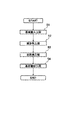
- step S1 a substrate carry-in process is performed. Specifically, the lift pins 23 of the chamber body 20 are stopped at the substrate delivery position, and the substrate 1 on which the coating film has been formed in the previous process is placed on the lift pins 23 by a robot hand or the like. Then, the lift pins 23 are accommodated up to the dry position, and the chamber lid 10 is lowered and comes into contact with the chamber body 20, whereby the substrate accommodating portion 30 is formed and the substrate 1 is held in the substrate accommodating portion 30.
- step S2 a slow exhaust process is performed. Specifically, the vacuum pump 31 of the suction decompression unit 3 is operated, and the suction control valve 36 is throttled to gently exhaust and decompress. That is, since a large amount of air is present in the substrate housing portion 30, there is a risk that drying unevenness may be formed in the coating film when an air flow due to exhaust is formed. In order to suppress the influence of drying unevenness due to the airflow, the atmosphere in the substrate housing portion 30 is gently exhausted.
- step S3 a quick exhaust process is performed in step S3. Specifically, the suction control valve 36 is opened and exhausted rapidly. That is, when it can be determined that the influence of the airflow due to the exhaust of the substrate housing portion 30 is small on the coating film, the suction control valve 36 is opened to perform the quick exhaust. In this embodiment, the timing for switching from slow exhaust to rapid exhaust is controlled by time.
- step S4 the main drying process is performed in step S4. Specifically, the leak control valve 46 is opened when the substrate container 30 reaches the saturated vapor pressure of the solvent forming the coating film, so that the pressure of the substrate container 30 is maintained at the saturated vapor pressure.
- the leak adjustment valve 46 is controlled so as to be gradually reduced in the vicinity of the saturated vapor pressure, instead of being maintained at a complete saturated vapor pressure. Thereby, it is possible to dry while sucking the coating liquid evaporated from the coating film, and it is possible to suppress the coating liquid floating in the substrate housing portion 30 from being mixed into the coating film as a foreign substance.
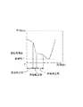
- the solid line shows the pressure change in the vacuum drying apparatus of the present invention
- the two-dot chain line shows the pressure change in the conventional vacuum drying apparatus.
- step S5 a substrate carry-out process is performed in step S5. Specifically, after completion of the main drying step, the suction operation of the suction decompression unit 3 is stopped, the release valve 6 is opened, the substrate housing unit 30 is returned to atmospheric pressure, and then the chamber lid unit 10 is raised. Let Then, the lift pins are raised to the substrate delivery position, and the substrate 1 is discharged by a robot hand or the like.
- the suction pressure reducing unit 3 (for example, the vacuum pump 31) has a large capacity because the pressure reducing unit 4 that supplies gas to the substrate housing unit 30 of the chamber unit 2 is provided. Even in such a case, the substrate housing portion 30 can be adjusted to a predetermined pressure. That is, when the substrate container 30 is sucked by the suction decompression unit 3, the substrate container 30 is depressurized, but when the gas is supplied from the decompression controller 4 to the substrate container 30, the supplied gas is exhausted and the substrate is discharged. The reduced pressure state of the housing part 30 can be relaxed.
- the pressure of the substrate housing unit 30 is set to a predetermined pressure (for example, the saturated vapor pressure of the solvent).
- the pressure state can be adjusted and maintained for a long time. Therefore, even when the capacity of the vacuum pump 31 for depressurizing the substrate housing portion 30 of the chamber portion 2 is increased, the coating film can be stably dried, and the adhesion between the substrate 1 and the coating film can be improved. Can do.
- the said embodiment demonstrated the example which has the air tank 41 in the pressure reduction adjustment part 4, and maintains the inside of the air tank 41 at a pressure higher than atmospheric pressure, the inside of the air tank 41 is maintained at atmospheric pressure. There may be. Further, the air tank 41 may not be provided, and the leak pipe 42 may be open to the atmosphere, or the air may be supplied only by the leak control valve 46.
- the said embodiment demonstrated the example in which the board
- the leak pipe 42 of the decompression adjusting unit 4 may be connected to the suction pipe 32.
- the leak pipe 42 is connected between the vacuum pump 31 and the on-off valve 35, and the gas in the air tank 41 is supplied to the suction pipe 32.
- the flow rate of the gas supplied to the suction pipe 32 can be adjusted by adjusting the leak adjustment valve 46.
- the gas supplied to the suction pipe 32 is immediately sucked by the vacuum pump 31.
- the leak pipe 42 is connected between the vacuum pump 31 and the opening / closing valve 35.
- the leakage pipe 42 is connected between the opening / closing valve 35 and the suction control valve 36 or between the suction control valve 36 and the suction connection. You may connect between the part 33.
Landscapes
- Engineering & Computer Science (AREA)
- Mechanical Engineering (AREA)
- General Engineering & Computer Science (AREA)
- Health & Medical Sciences (AREA)
- Life Sciences & Earth Sciences (AREA)
- Molecular Biology (AREA)
- Drying Of Solid Materials (AREA)
- Coating Apparatus (AREA)
Abstract
チャンバ部を減圧させる真空ポンプが大容量化された場合でも、塗布膜を安定して乾燥させることができる減圧乾燥装置及び減圧乾燥方法を提供する。具体的には、基板上に塗布された塗布膜を減圧環境下で乾燥させる減圧乾燥装置であって、基板が収容される基板収容部を有するチャンバ部と、基板収容部を吸引することにより基板収容部の圧力を減圧させる吸引減圧部と、を備え、チャンバ部には、基板収容部に気体を供給することにより吸引減圧部の減圧速度を抑えて基板収容部を所定の圧力に調節する減圧調節部を有する構成とする。
Description
本発明は、塗布装置により基板上に形成された塗布膜を乾燥させる乾燥装置及び乾燥方法であって、特に基板を収容するチャンバ内を大気圧よりも減圧させて乾燥させる減圧乾燥装置及び減圧乾燥方法に関するものである。
液晶ディスプレイやプラズマディスプレイ等のフラットパネルディスプレイには、基板上にレジスト液が塗布されたもの(塗布基板と称す)が使用されている。この塗布基板は、塗布装置により基板上にレジスト液が均一に塗布されることによって塗布膜が形成され、その後、減圧乾燥装置により塗布膜を乾燥させることにより生産される。
減圧乾燥装置は、チャンバ部の基板収容部に基板が収容された状態で、基板収容部を減圧させることにより基板上の塗布膜を乾燥させるようになっている(下記特許文献1参照)。具体的には、図6に示すように、基板100がチャンバ部101の基板収容部102に供給されると、基板100の裏面にプレートから突出した複数のピン103を当接させることによって支持される。そして、この支持された状態で基板収容部102を排気させると、基板収容部102が減圧環境下になることにより、基板100上の塗布膜を形成する溶媒が蒸発し塗布膜を乾燥させることができる。
具体的には、減圧乾燥装置は、図7に示すように基板収容部102の圧力が制御される。すなわち、チャンバ部101の基板収容部102に基板100が収容されると、風ムラ等の影響を抑えるため最初は緩やかに減圧される(緩排気工程)。そして、ある程度減圧させた後、急速に減圧させて(急排気工程)、チャンバ部101内の圧力を溶媒の飽和蒸気圧に調節する。すなわち、基板収容部102が飽和蒸気圧に調節された状態で塗布膜を乾燥させることにより(本乾燥工程)、塗布膜の乾燥状態を向上させて基板100と塗布膜との密着性、及び、塗布膜の品質を向上させることができる。
しかし、近年では、タクトタイムの短縮を図るため、チャンバ部101を減圧させる真空ポンプ104が大容量化されている。すなわち、真空ポンプ104の大容量化に伴って、真空ポンプ104の吸引力が大きくなっており、チャンバ部101を急速に減圧させることができるためタクトタイムを短縮させることができる。ところが、真空ポンプ104の吸引力が大きくなるに伴い、チャンバ部101内を飽和蒸気圧付近に調節することが困難になり高品質な塗布膜を形成するのが困難であるという問題があった。
すなわち、真空ポンプ104がチャンバ部101の基板収容部102に連結される配管経路105には、開度を調節する吸引調節弁106が設けられているが、真空ポンプ104の吸引力が大きくなると、少しの開度調節でもチャンバ内の圧力が大きく変化してしまう。そのため、基板収容部102が飽和蒸気圧に達した場合、吸引調節弁106で調節しても基板収容部102の圧力変化が大きく、基板収容部102を長時間に亘って飽和蒸気圧に維持することが困難であった。このように、真空ポンプ104が大容量化した場合には吸引調節弁106でチャンバ部101内を飽和蒸気圧付近に精度よく調節するのが難しくなり、塗布膜を安定して乾燥させるのが困難になるという問題があった。
本発明は、上記問題点に鑑みてなされたものであり、チャンバ部を減圧させる真空ポンプが大容量化された場合でも、塗布膜を安定して乾燥させることができる減圧乾燥装置及び減圧乾燥方法を提供することを目的としている。
上記課題を解決するために本発明の減圧乾燥装置は、基板上に塗布された塗布膜を減圧環境下で乾燥させる減圧乾燥装置であって、基板が収容される基板収容部を有するチャンバ部と、基板収容部を吸引することにより基板収容部の圧力を減圧させる吸引減圧部と、を備え、前記チャンバ部には、前記基板収容部に気体を供給することにより前記吸引減圧部の減圧速度を抑えて前記基板収容部を所定の圧力に調節する減圧調節部を有することを特徴としている。
上記減圧乾燥装置によれば、チャンバ部の基板収容部に気体を供給する減圧調節部を有しているため、吸引減圧部(例えば真空ポンプ)が大容量化された場合でも、基板収容部を所定の圧力に調節することができる。すなわち、吸引減圧部により基板収容部を吸引すると基板収容部が減圧されるが、減圧調節部から基板収容部に気体が供給されることにより、供給された気体が排気され基板収容部の減圧状態を緩和することができる。すなわち、吸引減圧部の大容量化により基板収容部が急速に減圧されると、減圧調節部から基板収容部に大量の気体が供給されることにより、基板収容部の減圧状態が緩和され、基板収容部の減圧速度を低下させることができる。すなわち、吸引減圧部から吸引される吸引量と減圧調節部から供給される気体の量を調節することにより、基板収容部の圧力を所定の圧力(例えば、塗布膜を形成する溶媒の飽和蒸気圧)に調節し、この圧力状態を維持することができる。したがって、チャンバ部の基板収容部を減圧させる真空ポンプが大容量化された場合でも、塗布膜を安定して乾燥させることができ、基板と塗布膜との密着性を向上させることができる。
また、具体的な吸引減圧部と減圧調節部の様態としては、前記吸引減圧部は、前記基板収容部に連結される吸引配管とこの吸引配管の開度を調節する吸引調節弁とを有しており、前記減圧調節部は、前記基板収容部に連結されるリーク配管とこのリーク配管の開度を調節するリーク調節弁とを有しており、前記吸引調節弁と前記リーク調節弁のそれぞれの開度が調節されることにより、前記基板収容部を所定の圧力に調節される構成にしてもよい。
また、前記吸引配管が前記基板収容部と連結される吸引連結部と、前記リーク配管が前記基板収容部と連結されるリーク連結部とは、前記吸引連結部と前記リーク連結部との間に基板が配置されるのを避けた位置に配置されている構成としてもよい。
この構成によれば、リーク配管から供給された気体が吸引配管に流れるが、基板はこれら吸引配管の吸引連結部とリーク配管のリーク連結部との間を避けて配置されるため、基板上に形成された塗布膜が気体の流れの影響を受けることを抑えることができる。
また、前記減圧調節部の前記リーク配管は、前記吸引配管を通じて前記基板収容部に連結されている構成としてもよい。
この構成によれば、リーク配管から供給された気体が基板収容部に供給されず、吸引配管を通じて吸引されるため、基板上に形成された塗布膜が気体の流れの影響を極力抑えることができる。
また、上記課題を解決するために本発明の減圧乾燥方法は、塗布膜が形成された基板をチャンバ部の基板収容部に収容し、基板収容部を減圧させて塗布膜を乾燥させる減圧乾燥方法であって、前記基板収容部を緩やかに排気して減圧させる緩排気工程と、少なくとも前記緩排気工程よりも急速に排気して減圧させる急排気工程と、前記基板収容部を所定の圧力に調節して塗布膜を乾燥させる本乾燥工程と、を有し、前記本乾燥工程では、基板収容部を排気させつつ、気体を供給することにより、前記基板収容部を前記所定の圧力に調節されることを特徴としている。
上記減圧乾燥方法によれば、本乾燥工程において、基板収容部を排気させることにより基板収容部を減圧し、この排気を維持した状態で基板収容部に気体が供給されるため、従来のように、基板収容部から排気される排気量を調節して減圧させる場合に比べて基板収容部の減圧状態が緩和され、基板収容部の減圧速度を低下させることができる。すなわち、基板収容部から排気される排気量(吸引量)と基板収容部に供給される気体の供給量を調節することにより、基板収容部の圧力を所定の圧力(例えば、塗布膜を形成する溶媒の飽和蒸気圧)に調節し、この圧力状態を維持することができる。したがって、チャンバ部の基板収容部を減圧させる真空ポンプが大容量化された場合でも、塗布膜を安定して乾燥させることができ、基板と塗布膜との密着性を向上させることができる。
本発明の減圧乾燥装置及び減圧乾燥方法によれば、チャンバ部内を減圧させる真空ポンプが大容量化された場合でも、塗布膜を安定して乾燥させることができる。
本発明に係る実施の形態を図面を用いて説明する。
図1、図2は、本発明の一実施形態における減圧乾燥装置を概略的に示す図であり、図1は、減圧乾燥装置のチャンバ蓋部10とチャンバ本体20が閉じた状態を示す図であり、図2はチャンバ蓋部10とチャンバ本体20が離間した状態を示す図である。
図1、図2に示すように、減圧乾燥装置は、基板1上に形成されたレジスト液などの塗布膜を乾燥させるものであり、基板1を収容するチャンバ部2と、このチャンバ部2を減圧させる吸引減圧部3とを備えている。そして、チャンバ部2に基板1を収容した状態でチャンバ部2内を減圧環境に維持することにより基板1上に形成された塗布膜を乾燥できるようになっている。
なお、以下の説明では、図1における紙面上側を減圧乾燥装置の上方、図1における紙面下側を減圧乾燥装置の下方として説明を進めることとする。
チャンバ部2は、チャンバ本体20とチャンバ蓋部10とを備えている。チャンバ蓋部10は、チャンバ本体20に対して開閉できるように形成されており、チャンバ蓋部10が閉状態では、図1に示すように、チャンバ蓋部10とチャンバ本体20とで基板1を収容する基板収容部30が形成されるようになっている。
チャンバ本体20は、塗布膜が形成された基板1を保持するものである。チャンバ本体20は、上面が開放された箱状部材であり、チャンバ本体20内に基板1を保持することができる。具体的には、チャンバ本体20は、平板形状のプレート部22を有しており、このプレート部22上に基板1を載置することができる。すなわち、プレート部22には、複数のピン孔が形成されており、このピン孔からリフトピン23が突出するようになっている。そして、この突出した複数のリフトピン23の先端部分に基板1が載置されることにより基板1が保持されるようになっている。
具体的には、プレート部22には、ピン孔に対応する位置にピン収容孔が形成されており、このピン収容孔にリフトピン23が埋設されている。このリフトピン23は、プレート部22の下側に設けられた駆動装置(不図示)と接続されており、この駆動装置を駆動させることにより、リフトピン23が昇降動作するとともに、任意の位置で停止できるようになっている。本実施形態では、リフトピン23が基部21内に収容される収容位置と、プレート部22から突出し基板1の受渡しを行う基板受渡位置(図2参照)と、乾燥工程を行う乾燥位置(図1参照)とに停止できるように設定されている。そして、リフトピン23が基板受渡位置に位置した状態で基板1がリフトピン23の先端部分に載置されると、リフトピンを所定量だけ下降させて基板1が乾燥位置に位置した状態で保持される。なお、このピン収容孔にはシールが設けられており、リフトピン23が突出した状態であってもピン収容孔から基板収容部30の大気の漏れを防止できるようになっている。
また、チャンバ蓋部10は、チャンバ本体20とともにチャンバ部2内に基板収容部30を形成するものである。チャンバ蓋部10は、チャンバ本体20に対して開閉できるようになっており、チャンバ蓋部10がチャンバ本体20に対して、昇降動作可能に形成されている。すなわち、チャンバ蓋部10がチャンバ本体20に対して上昇することによって開状態が形成され、チャンバ蓋部10がチャンバ本体20に対して下降し当接することによって閉状態が形成される。このチャンバ蓋部10は、チャンバ本体20に保持された基板1を覆う形状を有しており、チャンバ本体20と対面する平板状の平板部11と、この平板部11の外周縁からチャンバ本体20側に突出し、保持された基板1を囲む形状を有する側壁部12とを有している。すなわち、チャンバ蓋部10がチャンバ本体20に当接した状態では、チャンバ蓋部10の側壁部12がチャンバ本体20に当接することにより、基板1を収容可能な基板収容部30が形成されるようになっている。
チャンバ蓋部10の平板部11の基板収容部30側は、平滑な平坦状に形成されている。すなわち、基板収容部30を吸引した際に発生する気流(大気の流れ)が妨げられないように形成されている。また、基板収容部30側の裏面側には、リブ(不図示)が取付けられており、基板収容部30が減圧された場合に平板部11が変形するのを防止できるようになっている。これにより、基板収容部30内の大気が吸引されて基板収容部30内が減圧された場合であっても、平板部11の基板収容部30側が平坦度を維持することができ、基板収容部30の気流の乱れによって生じる乾燥ムラの発生を抑えることができるようになっている。
また、側壁部12の基板収容部30側は、平板部11と同様に平滑な平坦状に形成されており、基板収容部30の大気の流れが妨げられないように形成されている。また、側壁部12には、チャンバ本体20の基部21と当接する面にシール部材13が設けられている。このシール部材13は、保持された基板1を囲むように環状に形成されている。したがって、チャンバ蓋部10を下降させてチャンバ本体20に当接させた場合に、シール部材13がチャンバ本体20に当接して押圧されることにより、基板収容部30が密封状態にすることができる。
また、チャンバ部2には、吸引減圧部3が設けられており、吸引減圧部3により基板収容部30を減圧させることができる。吸引減圧部3は、吸引力を発生させる真空ポンプ31と、この真空ポンプ31と基板収容部30とを連結する吸引配管32とを有している。すなわち、吸引配管32が基板収容部30と吸引連結部33で連結されており、真空ポンプ31を作動させると吸引配管32を通じて吸引連結部33に吸引力が発生し、基板収容部30の大気が吸引される。これにより基板収容部30は、大気圧よりも小さい所定の圧力に減圧されるようになっている。
また、本実施形態における吸引連結部33は、チャンバ部2の底面中央部分であって、リフトピン23により乾燥位置に保持された基板1の中心位置に対向する位置に1つのみ設けられている。したがって、基板収容部30の大気は、基板1の中心位置に対向する位置に向かう気流が発生し、吸引連結部33を通じて排気される。なお、本実施形態では、1つの孔で構成される吸引連結部33が基板1の中心位置に対向する位置に1つのみ設けられているが、複数の孔から構成される吸引連結部33であってもよい。この場合であっても、複数の孔から構成される吸引連結部33の排気領域の中心位置が、保持された基板1の中心位置と対向する位置に設けてあれば、基板1の全周に亘って均一な吸引力を発生させることができる。
また、吸引配管32には、この吸引配管32を開閉する開閉弁35とは別に、吸引調節弁36が設けられている。この吸引調節弁36は、基板収容部30の吸引流量を調節するものである。すなわち、真空ポンプ31が作動した状態で吸引調節弁36を調節することにより、基板収容部30の吸引量を調節することができる。具体的には、真空ポンプ31の作動中に吸引調節弁36を開放すると基板収容部30から吸引される吸引量が最大になり基板収容部30の圧力を急速に減圧させることができる。また、吸引調節弁36を絞ることにより吸引量を低下させ、吸引調節弁36の開放時に比べて基板収容部30の減圧速度を低下させることができる。
また、チャンバ部2には、減圧調節部4が設けられており、基板収容部30の減圧速度を調整することができるようになっている。この減圧調節部4は、気体が充填されたエアタンク41と、このエアタンク41と基板収容部30とを連結するリーク配管42とを有している。
エアタンク41には、本実施形態では窒素ガスが収容されており、エアタンク41内の圧力は大気圧よりも大きい圧力に維持されている。すなわち、エアタンク41に貯留された窒素ガスが、リーク配管42を通じて基板収容部30との連結箇所であるリーク連結部43から供給されるようになっている。本実施形態では、リーク連結部43がチャンバ本体20の底面21に設けられており、吸引連結部33に近い位置に設けられている。したがって、リーク連結部43から供給された窒素ガスは、すぐに吸引連結部33から吸引されやすくなっている。なお、エアタンク41に貯留される気体は、窒素ガス以外にも空気等、塗布膜に化学的に影響しない気体であればよい。
また、リーク配管42には、リーク配管42を開閉する開閉弁45とは別に、リーク調節弁46が設けられている。このリーク調節弁46は、エアタンク41からの気体の流量を調節するものであり、基板収容部30に供給される気体の量を調節することができる。すなわち、リーク調節弁46の開度を最大にすることによりエアタンク41内の窒素ガスの最大量が基板収容部30に供給され、リーク調節弁46を絞ることにより供給される窒素ガスの量を少なくすることができる。
この減圧調節部4により、基板収容部30の減圧速度を調節することができる。すなわち、吸引減圧部3の真空ポンプ31の作動時には、基板収容部30が大気圧よりも小さい圧力に調整される。したがって、この減圧状態でリーク調節弁46を開くと、大気圧よりも大きい圧力に維持されたエアタンク41から、大気圧よりも小さい圧力に減圧された基板収容部30に窒素ガスが供給される。これにより、基板収容部30は、真空ポンプ31で吸引されるものの、新たに窒素ガスが供給されるため、真空ポンプ31のみで減圧される場合の減圧速度に比べて減圧速度が抑えられ、基板収容部30全体の圧力変化(低下)を抑えることができる。したがって、基板収容部30が、ある特定の圧力に達する際にリーク調節弁46を開くことにより、基板収容部30の圧力変化が抑えられ、基板収容部30を特定の圧力状態に維持したり、緩やかな減圧状態に維持したりすることができる。すなわち、真空ポンプ31として、大容量の真空ポンプ31を使用する場合であって、吸引調節弁36で減圧速度を調節しきれない場合であっても、減圧調節部4のリーク調節弁46を調節することにより基板収容部30の圧力を所定の圧力に調節することができる。
また、本実施形態では、リーク調節弁46は、基板収容部30の圧力に応じて設定圧力に調節されるようになっている。具体的には、チャンバ部2には、圧力計5が設けられており、この圧力値に応じてリーク調節弁46の開度が調節されるようになっている。例えば、基板収容部30の塗布膜を形成する溶媒の飽和蒸気圧に設定されている場合には、真空ポンプ31により基板収容部30が減圧され、飽和蒸気圧に到達するとリーク調節弁46が開かれる。そして、窒素ガスの供給量が多くなり基板収容部30の圧力が飽和蒸気圧よりも高くなるとリーク調節弁46が絞られる、というように基板収容部30の圧力状態がフィードバックされることにより基板収容部30の圧力が設定圧力に維持されるようになっている。また、設定圧力は、一定値以外にも、時間と共に減圧されるようにも設定できるようになっている。例えば、溶媒の飽和蒸気圧よりも少しだけ高い圧力から時間と共に徐々に飽和蒸気圧以下の圧力に減圧されるように設定することができ、基板収容部30を飽和蒸気圧付近で時間と共に緩やかに減圧させることができるようになっている。
また、リーク連結部43がチャンバ本体20の底面21に設けられているため、供給された窒素ガスがすぐに吸引連結部33から吸引される。すなわち、窒素ガスが供給されるリーク連結部43と、基板収容部30を吸引する吸引連結部33とが基板1を挟まない位置、すなわち、リーク連結部43と吸引連結部33とが、それらを結ぶ直線が基板1と交差しない位置に設けられているため、供給された窒素ガスが気流となって基板1上の塗布膜に乾燥ムラを誘発する要因となるのを抑えることができる。
また、チャンバ部2には、リリース弁6が設けられている。このリリース弁6は、開閉のみを行うことができ、チャンバ部2で乾燥処理が終了した後、基板収容部30の減圧状態を解放する場合に使用される。すなわち、減圧調節部4のリーク配管42及びリーク調節弁46とは別に設けられており、基板収容部30に供給される気体の量を調節することはできず、チャンバ部2の内外を連通状態にさせるものである。
次に、本実施形態における減圧乾燥装置を用いた乾燥処理動作について図3に示すフローチャートに基づいて説明する。
まず、ステップS1により、基板搬入工程が行われる。具体的には、チャンバ本体20のリフトピン23が基板受渡位置で停止しており、前工程で塗布膜が形成された基板1がロボットハンド等によりリフトピン23上に載置される。そして、リフトピン23が乾燥位置まで収容され、チャンバ蓋部10が下降しチャンバ本体20に当接することにより、基板収容部30が形成され、基板1が基板収容部30内に保持される。
次に、ステップS2により、緩排気工程が行われる。具体的には、吸引減圧部3の真空ポンプ31を作動させ、吸引調節弁36を絞って緩やかに排気し減圧する。すなわち、基板収容部30には大量の大気が存在しているため、排気による大気の流れが形成されると塗布膜に乾燥ムラが形成される虞がある。その気流による乾燥ムラ影響するのを抑えるため、基板収容部30内の大気を緩やかに排気する。
次に、ステップS3により急排気工程が行われる。具体的には、吸引調節弁36を開放して急速に排気する。すなわち、塗布膜に対して基板収容部30の排気による気流の影響が少ないと判断できる時点で吸引調節弁36を開放し急排気を行う。なお、本実施形態では、緩排気から急排気に切り替えるタイミングは、時間で制御されている。
次に、ステップS4により本乾燥工程が行われる。具体的には、基板収容部30が塗布膜を形成する溶媒の飽和蒸気圧に到達した際にリーク調節弁46が開かれることにより、基板収容部30の圧力が飽和蒸気圧に維持される。本実施形態では、完全な飽和蒸気圧に維持するのではなく、飽和蒸気圧付近で緩やかに減圧されるようにリーク調節弁46が制御される。これにより、塗布膜から蒸発した塗布液を吸引しつつ乾燥させることができ、基板収容部30に浮遊した塗布液が異物として塗布膜に混入するのを抑えることができる。ここで、図4では、実線が本発明の減圧乾燥装置における圧力変化を示し、二点鎖線が従来の減圧乾燥装置における圧力変化を示している。図4に示すように、本乾燥工程における減圧速度を抑えることができるため、乾燥が進行する本乾燥工程の時間を従来に比べて長く取ることができる。すなわち、従来のように吸引調節弁36のみで調節する場合に比べて基板収容部30を飽和蒸気圧に長時間維持することができるため、基板1と塗布膜との密着性が向上するなど、塗布膜の品質を安定させることができる。
次に、ステップS5により基板搬出工程が行われる。具体的には、本乾燥工程終了後、吸引減圧部3の吸引動作を停止させ、リリース弁6を開状態にすることにより基板収容部30を大気圧に戻した後、チャンバ蓋部10を上昇させる。そして、リフトピンを基板受渡位置まで上昇させてロボットハンド等により基板1を排出させる。
以上、上記実施形態の減圧乾燥装置によれば、チャンバ部2の基板収容部30に気体を供給する減圧調節部4を有しているため、吸引減圧部3(例えば真空ポンプ31)が大容量化された場合でも、基板収容部30を所定の圧力に調節することができる。すなわち、吸引減圧部3により基板収容部30を吸引すると基板収容部30が減圧されるが、減圧調節部4から基板収容部30に気体が供給されることにより、供給された気体が排気され基板収容部30の減圧状態を緩和することができる。すなわち、吸引減圧部3から吸引される吸引量と減圧調節部4から供給される気体の量を調節することにより、基板収容部30の圧力を所定の圧力(例えば、溶媒の飽和蒸気圧)に調節し、この圧力状態を長時間に亘って維持することができる。
したがって、チャンバ部2の基板収容部30を減圧させる真空ポンプ31が大容量化された場合でも、塗布膜を安定して乾燥させることができ、基板1と塗布膜との密着性を向上させることができる。
したがって、チャンバ部2の基板収容部30を減圧させる真空ポンプ31が大容量化された場合でも、塗布膜を安定して乾燥させることができ、基板1と塗布膜との密着性を向上させることができる。
また、上記実施形態では、減圧調節部4にエアタンク41を有し、エアタンク41内を大気圧よりも高い圧力に維持される例について説明したが、エアタンク41内を大気圧に維持されるものであってもよい。また、エアタンク41を備えず、リーク配管42が大気に開放される構成であってもよく、リーク調節弁46のみで大気を供給する構成であってもよい。
また、上記実施形態では、チャンバ部2に設けられた圧力計5のフィードバック制御により基板収容部30が飽和蒸気圧に調節される例について説明したが、フィードバック制御によらず、圧力計5が飽和蒸気圧を示した後、リーク調節弁46を開き、時間と共に開度が調節されるように構成してもよい。
また、上記実施形態では、減圧調節部4のリーク配管42が基板収容部30に連結される例について説明したが、リーク配管42が吸引配管32に連結されるものであってもよい。具体的には、図5に示すように、リーク配管42が真空ポンプ31と開閉弁35との間に接続されており、エアタンク41の気体が吸引配管32に供給されるようになっている。そして、リーク調節弁46を調節することにより吸引配管32に供給される気体の流量を調節することができる。そして、吸引配管32に供給された気体は、すぐに真空ポンプ31により吸引される。すなわち、吸引配管32に供給された気体が基板収容部30に入ることなく真空ポンプ31により吸引されるため、一度、気体が基板収容部30に供給される場合に比べて、基板収容部30内に供給されて気体が気流となって基板1上の塗布膜に乾燥ムラが形成されるのを抑えることができる。なお、図5の例では、リーク配管42が真空ポンプ31と開閉弁35との間に接続されているが、開閉弁35と吸引調節弁36との間、又は、吸引調節弁36と吸引接続部33との間に接続してもよい。
1 基板
2 チャンバ部
3 吸引減圧部
4 減圧調節部
30 基板収容部
32 吸引配管
33 吸引連結部
36 吸引調節弁
42 リーク配管
43 リーク連結部
46 リーク調節弁
2 チャンバ部
3 吸引減圧部
4 減圧調節部
30 基板収容部
32 吸引配管
33 吸引連結部
36 吸引調節弁
42 リーク配管
43 リーク連結部
46 リーク調節弁
Claims (5)
- 基板上に塗布された塗布膜を減圧環境下で乾燥させる減圧乾燥装置であって、
基板が収容される基板収容部を有するチャンバ部と、
基板収容部を吸引することにより基板収容部の圧力を減圧させる吸引減圧部と、
を備え、
前記チャンバ部には、前記基板収容部に気体を供給することにより前記吸引減圧部の減圧速度を抑えて前記基板収容部を所定の圧力に調節する減圧調節部を有することを特徴とする減圧乾燥装置。 - 前記吸引減圧部は、前記基板収容部に連結される吸引配管とこの吸引配管の開度を調節する吸引調節弁とを有しており、
前記減圧調節部は、前記基板収容部に連結されるリーク配管とこのリーク配管の開度を調節するリーク調節弁とを有しており、
前記吸引調節弁と前記リーク調節弁のそれぞれの開度が調節されることにより、前記基板収容部を所定の圧力に調節されることを特徴とする請求項1に記載の減圧乾燥装置。 - 前記吸引配管が前記基板収容部と連結される吸引連結部と、前記リーク配管が前記基板収容部と連結されるリーク連結部とは、前記吸引連結部と前記リーク連結部との間に基板が配置されるのを避けた位置に配置されていることを特徴とする請求項2に記載の減圧乾燥装置。
- 前記減圧調節部の前記リーク配管は、前記吸引配管を通じて前記基板収容部に連結されていることを特徴とする請求項2に記載の減圧乾燥装置。
- 塗布膜が形成された基板をチャンバ部の基板収容部に収容し、基板収容部を減圧させて塗布膜を乾燥させる減圧乾燥方法であって、
前記基板収容部を緩やかに排気して減圧させる緩排気工程と、
少なくとも前記緩排気工程よりも急速に排気して減圧させる急排気工程と、
前記基板収容部を所定の圧力に調節して塗布膜を乾燥させる本乾燥工程と、
を有し、
前記本乾燥工程では、基板収容部を排気させつつ、気体を供給することにより、前記基板収容部を前記所定の圧力に調節されることを特徴とする減圧乾燥方法。
Applications Claiming Priority (2)
| Application Number | Priority Date | Filing Date | Title |
|---|---|---|---|
| JP2016017622A JP6747815B2 (ja) | 2016-02-02 | 2016-02-02 | 減圧乾燥装置及び減圧乾燥方法 |
| JP2016-017622 | 2016-02-02 |
Publications (1)
| Publication Number | Publication Date |
|---|---|
| WO2017135018A1 true WO2017135018A1 (ja) | 2017-08-10 |
Family
ID=59500166
Family Applications (1)
| Application Number | Title | Priority Date | Filing Date |
|---|---|---|---|
| PCT/JP2017/001177 Ceased WO2017135018A1 (ja) | 2016-02-02 | 2017-01-16 | 減圧乾燥装置及び減圧乾燥方法 |
Country Status (3)
| Country | Link |
|---|---|
| JP (1) | JP6747815B2 (ja) |
| TW (1) | TWI717451B (ja) |
| WO (1) | WO2017135018A1 (ja) |
Cited By (1)
| Publication number | Priority date | Publication date | Assignee | Title |
|---|---|---|---|---|
| TWI887430B (zh) * | 2020-08-26 | 2025-06-21 | 日商松下知識產權經營股份有限公司 | 減壓乾燥裝置及減壓乾燥方法 |
Families Citing this family (2)
| Publication number | Priority date | Publication date | Assignee | Title |
|---|---|---|---|---|
| JP7316323B2 (ja) * | 2021-06-30 | 2023-07-27 | 株式会社Screenホールディングス | 減圧乾燥装置および減圧乾燥方法 |
| CN116007300A (zh) * | 2022-12-01 | 2023-04-25 | 深圳市美格真空科技有限公司 | 抽气控制方法以及脱水方法 |
Citations (3)
| Publication number | Priority date | Publication date | Assignee | Title |
|---|---|---|---|---|
| JP2006194577A (ja) * | 2005-12-21 | 2006-07-27 | Dainippon Screen Mfg Co Ltd | 基板処理装置および基板処理方法 |
| JP2006261379A (ja) * | 2005-03-17 | 2006-09-28 | Dainippon Screen Mfg Co Ltd | 減圧乾燥装置、排気装置および減圧乾燥方法 |
| JP2015191880A (ja) * | 2014-03-31 | 2015-11-02 | 東京エレクトロン株式会社 | 処理装置及び処理方法 |
Family Cites Families (2)
| Publication number | Priority date | Publication date | Assignee | Title |
|---|---|---|---|---|
| JP2005329303A (ja) * | 2004-05-19 | 2005-12-02 | Mitsubishi Chemicals Corp | 枚葉塗布部材の製造方法、減圧乾燥処理方法、および減圧乾燥処理装置 |
| KR101509830B1 (ko) * | 2009-09-07 | 2015-04-06 | 도쿄엘렉트론가부시키가이샤 | 감압건조장치 및 감압건조방법 |
-
2016
- 2016-02-02 JP JP2016017622A patent/JP6747815B2/ja not_active Expired - Fee Related
-
2017
- 2017-01-16 WO PCT/JP2017/001177 patent/WO2017135018A1/ja not_active Ceased
- 2017-01-17 TW TW106101494A patent/TWI717451B/zh not_active IP Right Cessation
Patent Citations (3)
| Publication number | Priority date | Publication date | Assignee | Title |
|---|---|---|---|---|
| JP2006261379A (ja) * | 2005-03-17 | 2006-09-28 | Dainippon Screen Mfg Co Ltd | 減圧乾燥装置、排気装置および減圧乾燥方法 |
| JP2006194577A (ja) * | 2005-12-21 | 2006-07-27 | Dainippon Screen Mfg Co Ltd | 基板処理装置および基板処理方法 |
| JP2015191880A (ja) * | 2014-03-31 | 2015-11-02 | 東京エレクトロン株式会社 | 処理装置及び処理方法 |
Cited By (1)
| Publication number | Priority date | Publication date | Assignee | Title |
|---|---|---|---|---|
| TWI887430B (zh) * | 2020-08-26 | 2025-06-21 | 日商松下知識產權經營股份有限公司 | 減壓乾燥裝置及減壓乾燥方法 |
Also Published As
| Publication number | Publication date |
|---|---|
| JP2017138022A (ja) | 2017-08-10 |
| TWI717451B (zh) | 2021-02-01 |
| JP6747815B2 (ja) | 2020-08-26 |
| TW201730494A (zh) | 2017-09-01 |
Similar Documents
| Publication | Publication Date | Title |
|---|---|---|
| JP6093172B2 (ja) | 減圧乾燥装置および減圧乾燥方法 | |
| KR101059365B1 (ko) | 진공 처리 장치 | |
| WO2017135018A1 (ja) | 減圧乾燥装置及び減圧乾燥方法 | |
| US11027970B2 (en) | Method of manufacturing semiconductor device | |
| JP6627243B2 (ja) | 基板の処理方法、及び基板の成膜方法 | |
| JP5344690B2 (ja) | 減圧乾燥装置 | |
| JP2008028208A (ja) | 基板貼合装置 | |
| JP2011165691A (ja) | 減圧乾燥方法及び減圧乾燥装置 | |
| JP2018109473A (ja) | 減圧乾燥装置 | |
| JP2006261379A (ja) | 減圧乾燥装置、排気装置および減圧乾燥方法 | |
| KR100730449B1 (ko) | 감압 건조 장치 | |
| JP6855334B2 (ja) | 基板処理装置及び基板処理方法 | |
| CN101363681A (zh) | 减压干燥装置 | |
| JP4771893B2 (ja) | 基板保持装置 | |
| TW201710634A (zh) | 減壓乾燥裝置及減壓乾燥方法 | |
| JP2012247507A (ja) | 基板の貼り合せ装置 | |
| TWI690011B (zh) | 密著強化處理裝置及密著強化處理方法 | |
| KR20130016359A (ko) | 기판 처리 방법 및 기판 처리 시스템 | |
| JP2013029259A (ja) | 減圧乾燥装置 | |
| JP4274168B2 (ja) | プラズマ処理装置およびプラズマ処理方法 | |
| KR102040246B1 (ko) | 기판처리장치 및 방법 | |
| JP2008084924A (ja) | 伝熱ガス供給機構および伝熱ガス供給方法、ならびに基板処理装置および基板処理方法 | |
| JP2011056425A (ja) | 減圧乾燥装置 | |
| US20200115227A1 (en) | Method of manufacturing semiconductor device | |
| JP2007235094A (ja) | 減圧乾燥処理装置 |
Legal Events
| Date | Code | Title | Description |
|---|---|---|---|
| 121 | Ep: the epo has been informed by wipo that ep was designated in this application |
Ref document number: 17747180 Country of ref document: EP Kind code of ref document: A1 |
|
| NENP | Non-entry into the national phase |
Ref country code: DE |
|
| 122 | Ep: pct application non-entry in european phase |
Ref document number: 17747180 Country of ref document: EP Kind code of ref document: A1 |