WO2017134872A1 - 投射型映像表示装置 - Google Patents
投射型映像表示装置 Download PDFInfo
- Publication number
- WO2017134872A1 WO2017134872A1 PCT/JP2016/081628 JP2016081628W WO2017134872A1 WO 2017134872 A1 WO2017134872 A1 WO 2017134872A1 JP 2016081628 W JP2016081628 W JP 2016081628W WO 2017134872 A1 WO2017134872 A1 WO 2017134872A1
- Authority
- WO
- WIPO (PCT)
- Prior art keywords
- cooling unit
- cooling
- projection
- display device
- heat
- Prior art date
- Legal status (The legal status is an assumption and is not a legal conclusion. Google has not performed a legal analysis and makes no representation as to the accuracy of the status listed.)
- Ceased
Links
Images



Classifications
-
- G—PHYSICS
- G03—PHOTOGRAPHY; CINEMATOGRAPHY; ANALOGOUS TECHNIQUES USING WAVES OTHER THAN OPTICAL WAVES; ELECTROGRAPHY; HOLOGRAPHY
- G03B—APPARATUS OR ARRANGEMENTS FOR TAKING PHOTOGRAPHS OR FOR PROJECTING OR VIEWING THEM; APPARATUS OR ARRANGEMENTS EMPLOYING ANALOGOUS TECHNIQUES USING WAVES OTHER THAN OPTICAL WAVES; ACCESSORIES THEREFOR
- G03B21/00—Projectors or projection-type viewers; Accessories therefor
-
- G—PHYSICS
- G03—PHOTOGRAPHY; CINEMATOGRAPHY; ANALOGOUS TECHNIQUES USING WAVES OTHER THAN OPTICAL WAVES; ELECTROGRAPHY; HOLOGRAPHY
- G03B—APPARATUS OR ARRANGEMENTS FOR TAKING PHOTOGRAPHS OR FOR PROJECTING OR VIEWING THEM; APPARATUS OR ARRANGEMENTS EMPLOYING ANALOGOUS TECHNIQUES USING WAVES OTHER THAN OPTICAL WAVES; ACCESSORIES THEREFOR
- G03B21/00—Projectors or projection-type viewers; Accessories therefor
- G03B21/14—Details
- G03B21/16—Cooling; Preventing overheating
-
- H—ELECTRICITY
- H04—ELECTRIC COMMUNICATION TECHNIQUE
- H04N—PICTORIAL COMMUNICATION, e.g. TELEVISION
- H04N9/00—Details of colour television systems
- H04N9/12—Picture reproducers
- H04N9/31—Projection devices for colour picture display, e.g. using electronic spatial light modulators [ESLM]
Definitions
- the present invention relates to a projection display apparatus, and more particularly to a technique effective for cooling a light source used in the projection display apparatus.
- an LED (Light Emitting Diode) light source that is, a light emitting diode has been widely used as a light source in order to achieve downsizing and stable operation of the device It's being used.
- the light emitting diode has a characteristic change with respect to temperature, and the amount of light decreases due to, for example, an increase in temperature due to ambient temperature and heat generation of the light emitting diode.
- the amount of light decreases, the image quality decreases.
- the light emitting diode used as the light source is provided with a radiator or the like to reduce a decrease in the light amount of the light emitting diode.
- Patent Document 1 a technique that suppresses the temperature rise of the phosphor by moving the phosphor layer and changing the irradiation position of the excitation light is known (for example, Patent Document 1).
- the temperature characteristics of the light emitting diodes may differ depending on the color.
- the coolers provided in the light emitting diodes of the respective colors may have different cooling capacities depending on the positions of the coolers.
- the temperature of the central portion of the projector housing tends to be higher than the vicinity of the intake port for taking in outside air.
- a cooling device laid out at a location distant from the intake port has a lower cooling efficiency than a cooler arranged near the intake port due to space constraints.
- the layout of the coolers of the respective colors in the projector housing is determined without considering the temperature characteristics for each color of the light emitting diodes, the balance of the temperature rise of the three light emitting diodes is lost, and the three light emitting diodes are lost. Therefore, the balance of the amount of emitted light is not the required ratio, and the color balance of the projector becomes strange. Or, if the color balance is adjusted according to the light amount of the light source having a small light emission amount, the white illuminance of the projector itself is lowered.
- An object of the present invention is to more suitably cool light emitting diodes of a plurality of colors.
- a typical projection-type image display device is a display device that projects an image using white light.
- This projection display apparatus has first to third light sources and first to third cooling units.
- the first to third light sources emit light of different colors to generate white light.
- the first cooling unit cools the first light source.
- the second cooling unit cools the second light source.
- the third cooling unit cools the third light source.
- the first light source is the light source with the greatest change in temperature characteristics.
- the first cooling unit that cools the first light source is arranged to be cooled more preferentially than the second or third cooling unit.
- the first cooling unit is arranged at a position closest to the intake port through which the cooling air is taken.
- the first to third cooling units each have one or more heat pipes.
- the condensing part of the heat pipe in the first cooling unit is arranged at a position closest to the intake port into which the cooling air is taken.
- FIG. 5 is an explanatory diagram showing an example of a temperature characteristic of an LED included in the projection type video display device of FIGS.
- the constituent elements are not necessarily indispensable unless otherwise specified and apparently essential in principle. Needless to say.
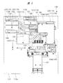
- FIG. 1 is a front perspective view showing an example of an internal layout of the projection display apparatus 100 according to the first embodiment.
- FIG. 2 is a perspective view of the back side of FIG.
- FIG. 3 is a plan view of FIG.
- FIG. 4 is a left side view of FIG.
- cooling fans 106 to 108 shown in FIG. 1 are omitted for easy understanding of the layout of the cooling unit 105.
- the projection display apparatus 100 includes a projection optical system 101, a display element 102, an illumination optical system 103, a light source unit 104, cooling units 114 to 117, cooling fans 106 to 108, a heat sink 109, and the like. It is provided in a rectangular parallelepiped casing 110 indicated by a two-dot chain line in FIG.
- the projection optical system 101 is an optical system that projects an image on a screen (not shown), and includes, for example, a projection lens (or an optical element such as a mirror).
- a projection lens or an optical element such as a mirror
- one end for projecting an image is provided so as to be exposed from the front surface which is one side surface of the housing 110.
- an exhaust port 110a for discharging air taken in by the cooling fans 106 to 108 is provided on the left side of one end of the projection lens.
- a display element 102 is provided on the other end side of the projection lens.
- the display element 102 is an element that generates an image to be projected.
- a DMD Digital Micromirror Device
- a panel or the like is used.
- a heat sink 109 is attached to the display element 102.
- the heat sink 109 is made of, for example, aluminum, and diffuses and dissipates heat generated when the display element 102 is driven.
- the haze display element 102 generates an image to be projected based on a drive signal corresponding to a video signal output from a display element driving unit (not shown) included in the projection display apparatus 100.
- the display element 102 is not limited to the DMD panel, and may be a transmissive liquid crystal panel or a reflective liquid crystal panel, for example.
- the illumination optical system 103 includes a parallel portion 103a that extends parallel to the projection optical system 101, and a right-angle portion 103b that extends in a right-angle direction from the tip of the parallel portion.
- the illumination optical system 103 is an optical system that condenses illumination light generated by a light source unit 104 (to be described later), irradiates the display element 102 more uniformly.
- the light source unit 104 generates projection illumination light and includes three LEDs 111 to 113.
- the LED 111 as the first light source is a light emitting diode that emits red light.
- the LED 112 as the second light source is a light emitting diode that emits green light.
- the LED 113 as the third light source is a light emitting diode that emits blue light.
- LED111 and LED113 consist of a plane light emission type, for example.
- the LED 112 is a light emitting diode having a rod lens.
- the rod lens is a cylindrical lens having a refractive index distribution with a quadratic distribution in the radial direction.
- the rod lens has a configuration in which the rod lens is arranged in, for example, an array, and the light source emitted from the LED 112 is configured by the rod lens. The light is emitted from the light emitting surface.
- the LED 111 is provided on one side of the right angle portion 103b of the illumination optical system 103, and the LED 113 is provided on the other side of the right angle portion 103b facing the one side.
- the LED 112 is provided at the tip of the illumination optical system 103.
- the projection display apparatus 100 has a power supply unit (not shown).
- the power supply unit receives power supplied from an external power supply and supplies power for operation to each unit including the light source unit 104 and the display element driving unit described above.
- the cooling unit 114 which is the first cooling unit cools the LED 111.
- the cooling unit 114 includes, for example, three heat pipes 120 and heat radiating fin portions 121 that cool the heat pipes 120.
- the heat pipe 120 is obtained by enclosing a working liquid such as water in a metal pipe made of, for example, copper.
- a working liquid such as water
- a metal pipe made of, for example, copper the number of this heat pipe is increased / decreased according to the emitted-heat amount of LED.
- One end of the heat pipe 120 and the vicinity thereof are attached to the heat radiating surface facing the light emitting surface of the LED 111.
- the part attached to the heat radiating surface side of the LED 111 is defined as an evaporation unit.
- a heat radiating fin 121 is attached to one end of the heat pipe 120 and the vicinity thereof.
- the part to which the radiation fin part 121 is attached is defined as a condensing part.
- the heat radiation fin 121 is made of, for example, a plate-like metal material, and is made of, for example, aluminum or copper. In the plane of the metal plate, circular holes substantially the same as the heat pipe 120 are formed.
- the heat pipe 120 is inserted into a circular hole formed in the metal plate. In addition, when it can fully cool only with the heat pipe 120, you may make the radiation fin part 121 unnecessary.
- the heat dissipating fin portion 121 forms an air guide path in the direction of the arrow 131 in the heat dissipating fin portion 121 by a plurality of fin plates orthogonal to the heat pipe 120 inserted into the circular hole. That is, the cooling air that cools the heat pipe 120 flows in the direction of the arrow 131 through the air guide path.
- the vapor generated by the boiling flows from the evaporating part, that is, the high temperature side to the condensing part, that is, the low temperature side due to the pressure difference.
- the heat of condensation is released at the condensing part.
- the working liquid condensed by the capillary phenomenon returns to the evaporation section.
- the heat pipe 120 transports heat by the phase change of evaporation and condensation of the enclosed working liquid.
- the cooling unit 115 that is the second cooling unit cools the LED 112.
- the cooling unit 115 also includes three heat pipes 122 and heat radiating fin portions 123 that cool the heat pipes 122.
- the cooling unit 116 which is the second cooling unit also includes three heat pipes 124 and heat radiation fin portions 125 for cooling the heat pipes 124.
- a plurality of fin plates orthogonal to the heat pipe inserted into the circular hole form an air guide path in the direction of the arrow 132 in the heat dissipating fin portion 121. is doing. That is, the cooling air for cooling the heat pipe 122 and the heat pipe 124 flows in the direction of the arrow 132 through the air guide path.
- the cooling unit 117 which is the third cooling unit has three heat pipes 126 and a heat radiation fin portion 127 for cooling the heat pipes 126.
- the configuration of these cooling units 115 to 117 is the same as that of the cooling unit 114.
- the heat radiating fin portion 127 in this embodiment also forms an air guide path in the direction of arrow 133 in the heat radiating fin portion 121 by a plurality of fin plates orthogonal to the heat pipe 126 inserted into the circular hole. That is, the cooling air for cooling the heat pipe 126 flows in the direction of the arrow 133 through the air guide path.
- the cooling units 115 and 116 cool the heat generated from the rod lens by the heat pipes 122 and 124, unlike the cooling units 114 and 117.
- the cooling fans 106 to 108 are fans that take in outside air as cooling air into the casing 110 from the outside.
- the outside air taken in by the cooling fans 106 to 108 releases the heat generated by the light source unit 104 to the outside and suppresses the high temperature.
- intake ports 110b and 110c for taking in outside air as cooling air from the left to the right are provided on the rear surface, which is the surface facing the front surface of the housing 110 from which one end of the projection lens is exposed. Each is provided.
- a cooling fan 107 is attached to the intake port 110b, and a cooling fan 106 is attached to the intake port 110c.
- the cooling fans 106 and 107 suck the outside air as cooling air from the outside of the housing 110 and take the cooling air into the housing 110.
- the cooling air taken in by the cooling fans 106 and 107 is discharged from the exhaust port 110a.
- the heat dissipating fin portion 121 is laid out on the downstream side of the cooling fan 106, that is, on the discharge side of the cooling fan 106. That is, the condensing part and the heat radiating fin part 121 of the heat pipe 120 are provided at a position closest to the intake port 110c.
- the cooling fan 106 and the radiating fin portion 121 are arranged in a substantially straight line. Further, the exhaust direction of the cooling fan 106 and the direction 131 of the air guide path of the radiating fin portion 121 are aligned in substantially the same direction. As a result, the air sucked by the cooling fan 106 is efficiently applied to the radiating fin portion 121, and the air radiated by the radiating fin portion 121 can be efficiently discharged. Moreover, since the heat radiating fin portion 121 including the heat pipe 120 is located closest to the intake port 110c, it can be cooled by outside air having a low temperature.
- a radiating fin portion 123 is laid out on the downstream side of the cooling fan 107, that is, on the cooling air discharge side of the cooling fan 107, and a radiating fin portion 125 is laid out on the downstream side of the radiating fin portion 123. ing. Further, a cooling fan 108 including a condensing part is laid out on the downstream side of the radiating fin part 125.
- the cooling fan 107, the radiating fin portion 123, the radiating fin portion 125, and the cooling fan 108 are arranged substantially linearly. Further, the exhaust direction of the cooling fan 107, the direction 132 of the airflow guide path of the radiating fin portion 123 and the direction of the airflow guide path of the radiating fin portion 125, and the intake direction of the cooling fan 108 are all aligned in substantially the same direction. As a result, the air sucked by the cooling fan 107 is efficiently applied to the radiating fin portions 123 and 125, and the air radiated by the radiating fin portions 123 and 125 can be efficiently discharged.
- the cooling air sucked in by the cooling fan 107 from the intake port 110b passes through the heat radiation fin portions 123 and 125 and the cooling fan 108, and a flow path exhausted from the exhaust port 110a is formed. Further, the cooling air sucked by the cooling fan 106 from the intake port 110c passes through the radiating fin portion 121 to form a flow path exhausted from the exhaust port 110a.
- FIG. 5 is an explanatory diagram showing an example of temperature characteristics of the LEDs 111 to 113 included in the projection display apparatus 100 of FIGS.
- the vertical axis represents the light emission amount
- the horizontal axis represents the LED temperature, that is, the LED chip temperature.
- the temperature characteristic of the LED 111 that emits red light is indicated by R
- the temperature characteristic of the LED 112 that emits green light is indicated by G
- the temperature characteristic of the LED 113 that emits blue light is indicated by B.
- the temperature characteristics of the LEDs 111 to 113 vary depending on the color of light emission as shown in the figure.
- the amount of light emission increases and decreases with respect to the chip temperature.
- the increase / decrease of the light emission amount with respect to the chip temperature is smaller than that of the LED 111.
- the chip temperature is 40 ° C.
- the light emission amount of the LED 111 is the lowest, but it is not much different from the LEDs 112 and 113.
- the chip temperature is 70 ° C.
- the light emission amount of the LED 111 is greatly reduced as compared with the LEDs 112 and 113.
- the decrease rate of the light emission amount of the LED 111 is larger than that of the LEDs 112 and 113. Therefore, in order to maintain “1.0”, which is the light emission amount of the LEDs 111 to 113 assumed when performing white display, temperature management of the LED 111 emitting red light is important, and the LED 111 is connected to the other LEDs 112 and 113. It is desirable to cool more efficiently than the above.
- the LED 111 that emits red light can be preferentially cooled.
- the radiating fin portion 121 of the cooling unit 114 that cools the LED 111 is laid out at a position closest to the air inlet 110c.
- the LED having the largest temperature characteristic change next to the LED 111 is the LED 112 that emits green light, as shown in FIG.
- the LED 112 does not change as much as the temperature of the LED 111, it is desirable to cool the LED 112 in preference to the LED 113 that emits blue light. Therefore, as described with reference to FIGS. 1 to 4, the radiating fin portion 123 of the cooling unit 115 that cools the LED 112 is laid out at a position closest to the intake port 110b.
- the radiating fin portion 127 for cooling the LED 113 is laid out closer to the exhaust port 110a than the radiating fin portions 123 and 125. Thereby, LED113 becomes difficult to be cooled. However, since the LED 113 is the LED with the least change in temperature characteristics as described above, it is possible to prevent the light emission amount from being significantly reduced.
- the light emission amount of the LED 111 is greatly reduced due to heat generation, so that the light emission amount is greatly reduced even in the same environment.
- the LED 111 whose light emission amount greatly decreases due to heat generation can be preferentially cooled, so that a significant decrease in the light emission amount of the LED 111 can be reduced. This contributes to reducing the color balance collapse.
- the radiating fin portion 127 that cools the LED 113 is laid out closer to the exhaust port 110a than the radiating fin portions 123 and 125.
- the LED 112 and the LED 113 have a large temperature. If there is no difference in characteristics, the layout of the heat radiating fins 123, 125, 127 may be changed. In that case, the radiating fin portion 127 is provided at a position closest to the intake port 110b, and the radiating fin portions 123 and 125 are laid out closer to the exhaust port 110a than the radiating fin portion 127 is.
- the radiating fin portion 127 is restricted in the height direction, in other words, the length from the top surface to the bottom surface of the housing 110. Specifically, the above-described power supply unit (not shown) is laid out below the radiating fin unit 127.
- the total height of the heat radiating fin portion 127 is lower than that of the heat radiating fin portions 123 and 125, and the width direction from the front surface to the back surface of the housing 110 is wider than that of the heat radiating fin portions 121, 123, and 125. It has become the composition.
- the radiating fin portions 121, 123, and 125 have a vertically long shape when viewed from the side as shown in FIG. 4, but the radiating fin portions 127 have a horizontally long shape.
- the three heat pipes 126 of the radiating fin portion 127 are arranged in such a way that the cooling air flows from the intake ports 110b and 110c, which are upstream of the cooling air, to the exhaust port 110a, which is downstream of the cooling air. It is provided so as to extend in a second direction which is a direction crossing the direction of one.
- Each heat pipe 126 is arranged so that the center of the heat pipe is shifted in a third direction intersecting with the first and second directions.
- the first direction is a direction indicated by an arrow A in FIGS. 3 and 4, a direction from left to right in FIG. 4, and a direction from top to bottom in FIG. 3.
- the second direction is the direction indicated by the arrow B in FIG. 3, and is the depth direction in FIG.
- the third direction is the direction indicated by the arrow C in FIG. 4 and is the vertical direction in FIG.
- the heat pipe 126a closest to the back surface of the housing 110 shown in FIG. 3 is provided at the highest position, and the heat pipe 126c closest to the front surface of the housing 110 is provided at the lowest position.
- the remaining one heat pipe 126b sandwiched between the heat pipe 126a and the heat pipe 126c is provided at a position lower than the heat pipe 126a and higher than the heat pipe 126c.
- the cooling efficiency of the heat pipes 126a to 126c can be improved by shifting the heights of the three heat pipes 126a to 126c.
- the cooling air heated by the heat pipe 126a will hit the heat pipe 126b. Further, the cooling pipe warmed by the heat pipes 126a and 126b is applied to the heat pipe 126c. Therefore, the closer the heat pipe is to the front surface of the housing 110, the higher the cooling air temperature and the lower the cooling efficiency.
- the first device is an air inlet 110b that is arranged on the back surface of the projection display 100 shown in FIG. 3 for all the directions of the air guide paths of the heat dissipating fin portions 121, 123, 125, and 127 of the plurality of cooling units. And approximately perpendicular to the direction of 110c, that is, the direction of arrow A.
- the large flow of the cooling air in the air guide passages of the heat radiating fin portions 121, 123, 125, and 127 from the intake port on the rear surface of the projection display apparatus 100 can be easily aligned in the direction of the arrow A. Thereby, it is possible to form a flow of cooling air that efficiently travels around at least a plurality of cooling units in the projection display apparatus 100.
- this cooling unit if one or more cooling devices such as a cooling fan that generates a positive pressure are arranged downstream of the direction of arrow A or a cooling device that generates a negative pressure is arranged downstream of the direction of arrow A, A large flow of cooling air in the direction of arrow A described above can be generated at least around the plurality of cooling units, and the plurality of cooling units can be efficiently cooled.
- a cooling fan that generates a positive pressure are arranged downstream of the direction of arrow A or a cooling device that generates a negative pressure is arranged downstream of the direction of arrow A
- the second idea is that when a cooling fan is arranged as the cooling device, it is arranged in a layout in which intake and exhaust are performed in the direction of the arrow A described above using an axial fan. Thereby, it is possible to generate a flow of cooling air that is directly connected to a large flow of cooling air in the direction of arrow A described above.
- the exhaust port 110 a is disposed on the front surface of the projection display apparatus 100. This makes it easy to align the large flow of cooling air in the projection display apparatus 100 in the direction of arrow A. However, the direction of the cooling air further downstream that has cooled all the cooling units is not necessarily aligned with the direction of arrow A. Therefore, an exhaust port may be provided on the side surface of the projection display apparatus 100, or a plurality of holes may be provided on the side face or front face of the projection display apparatus 100 to exhaust in a diffuse manner.
- the projection display apparatus 100 that can cool the light emitting diodes of a plurality of colors more suitably can be realized.
- a part of the configuration of one embodiment can be replaced with the configuration of another embodiment, and the configuration of another embodiment can be added to the configuration of one embodiment. .
Landscapes
- Physics & Mathematics (AREA)
- General Physics & Mathematics (AREA)
- Engineering & Computer Science (AREA)
- Multimedia (AREA)
- Signal Processing (AREA)
- Projection Apparatus (AREA)
- Video Image Reproduction Devices For Color Tv Systems (AREA)
Abstract
投射型映像表示装置においてより好適に複数色の発光ダイオードを冷却する。投射型映像表示装置100は、白色光を用いて映像を投影する。この投射型映像表示装置100は、LED111、LED112、LED113、冷却ユニット114、冷却ユニット115、および冷却ユニット116を有する。LED111~LED113は、白色光を生成する。冷却ユニット114は、LED111を冷却する。冷却ユニット115は、LED112を冷却する。冷却ユニット116は、LED113を冷却する。LED111は、最も温度特性の変化が大きい光源である。LED111を冷却する冷却ユニット114は、冷却ユニット115,116よりも優先的に冷却されるように配置される。
Description
本発明は、投射型映像表示装置に関し、特に、投射型映像表示装置に用いられる光源の冷却に有効な技術に関する。
近年、スクリーンなどに映像を投射する投影型映像表示装置、すなわちプロジェクタなどでは、小型化および装置の安定的な動作を実現するために、LED(Light Emitting Diode)光源、すなわち発光ダイオードが光源として広く利用されている。
発光ダイオードは、温度に対する特性変化があり、例えば周辺温度および発光ダイオードの発熱などによる温度上昇によって光量が低下してしまう。光量が低下してしまうと、画質の低下などが発生してしまう。そのため、光源として用いられる発光ダイオードには、放熱器などが設けられており、発光ダイオードの光量低下を低減している。
この種のプロジェクタにおける発光効率の低下を低減する技術としては、例えば蛍光体層を移動させて励起光の照射位置を変化させることにより蛍光体の温度上昇を抑制するものが知られている(例えば特許文献1参照)。
例えば、赤色、青色、緑色の3つの発光ダイオードをLED光源として有する場合、発光ダイオードの温度特性は色によって異なっていることがある。さらに、各色の発光ダイオードにそれぞれ設けられる冷却器は、該冷却器の位置などによって冷却能力が異なってしまう場合がある。
例えば、外気を取り入れる吸気口近傍よりもプロジェクタ筐体の中心部は、温度が高くなる傾向にある。そのため、スペース上の制約などから、吸気口から離れた場所にレイアウトされた冷却器は、吸気口近傍に配置された冷却器よりも冷却効率が低下してしまうことになる。
その結果、発光ダイオードの色毎の温度特性を考慮せずにプロジェクタ筐体内の各色の冷却器のレイアウトを定めると、前記3つの発光ダイオードの温度上昇のバランスが崩れてしまい、該3つ発光ダイオードの発光量のバランスが求める比率にならずプロジェクタの色バランスがおかしくなることになる。または、発光量の小さい色の光源の光量に合わせて色バランスを調整するとプロジェクタの白色照度自体が低下してしまうことになる。
また、空冷冷却において、プロジェクタ筐体内の限られた空間で前記3つの発光ダイオードの冷却器をいかに効率的に冷やすかも課題となる。
本発明の目的は、より好適に複数色の発光ダイオードを冷却することにある。
本発明の前記ならびにその他の目的と新規な特徴については、本明細書の記述および添付図面から明らかになるであろう。
本願において開示される発明のうち、代表的なものの概要を簡単に説明すれば、次のとおりである。
すなわち、代表的な投射型映像表示装置は、白色光を用いて映像を投影する表示装置である。この投射型映像表示装置は、第1~第3の光源、および第1~第3の冷却ユニットを有する。
第1~第3の光源は、異なる色の光をそれぞれ発光して白色光を生成する。第1の冷却ユニットは、第1の光源を冷却する。第2の冷却ユニットは、第2の光源を冷却する。第3の冷却ユニットは、第3の光源を冷却する。
第1の光源は、最も温度特性の変化が大きい光源である。第1の光源を冷却する第1の冷却ユニットは、第2または第3の冷却ユニットよりも優先的に冷却されるように配置される。
第1の冷却ユニットは、冷却風が取り入れられる吸気口に最も近い位置に配置される。また、第1~第3の冷却ユニットは、1つ以上のヒートパイプをそれぞれ有する。特に、第1の冷却ユニットにおけるヒートパイプの凝縮部が、冷却風が取り入れられる吸気口に最も近い位置に配置される。
本願にかかる発明によれば、より好適に複数色の発光ダイオードを冷却することが可能となる。
以下の実施の形態においては便宜上その必要があるときは、複数のセクションまたは実施の形態に分割して説明するが、特に明示した場合を除き、それらはお互いに無関係なものではなく、一方は他方の一部または全部の変形例、詳細、補足説明等の関係にある。
また、以下の実施の形態において、要素の数等(個数、数値、量、範囲等を含む)に言及する場合、特に明示した場合および原理的に明らかに特定の数に限定される場合等を除き、その特定の数に限定されるものではなく、特定の数以上でも以下でもよい。
さらに、以下の実施の形態において、その構成要素(要素ステップ等も含む)は、特に明示した場合および原理的に明らかに必須であると考えられる場合等を除き、必ずしも必須のものではないことは言うまでもない。
同様に、以下の実施の形態において、構成要素等の形状、位置関係等に言及するときは特に明示した場合および原理的に明らかにそうではないと考えられる場合等を除き、実質的にその形状等に近似または類似するもの等を含むものとする。このことは、上記数値および範囲についても同様である。
また、実施の形態を説明するための全図において、同一の部材には原則として同一の符号を付し、その繰り返しの説明は省略する。
〈投射型映像表示装置の構成例〉
以下、実施の形態を詳細に説明する。
以下、実施の形態を詳細に説明する。
図1は、本実施の形態1による投射型映像表示装置100の内部レイアウトの一例を示す正面側の斜視図である。図2は、図1の背面側の斜視図である。図3は、図1の平面図である。図4は、図1の左側面図である。
なお、図2では、冷却部105のレイアウトをわかりやすくするために、図1に示した冷却ファン106~108を省略している。
投射型映像表示装置100は、投射光学系101、表示素子102、照明光学系103、光源部104、冷却ユニット114~117、冷却ファン106~108、およびヒートシンク109などを有しており、これらが図3の二点鎖線にて示す直方体形状の筐体110に設けられている。
投射光学系101は、映像を図示しないスクリーンに投射する光学系であり、例えば投射レンズ(またはミラーなどの光学要素でもよい)を有する。この投射レンズにおいて、映像を投射する一方端が筐体110のある1つの側面である前面から露出するように設けられている。また、筐体110の前面において、投射レンズの一方端の左側には、冷却ファン106~108によって取り入れられた空気を排出する排気口110aが設けられている。
投射レンズの他方端側には、表示素子102が設けられている。この表示素子102は、投射する映像を生成する素子であり、例えばDMD(Digital Micromirror Device)(登録商標)パネルなどが用いられる。
表示素子102には、ヒートシンク109が取り付けられている。このヒートシンク109は、例えばアルミニウムなどからなり、表示素子102が駆動した際に発生する熱を拡散して放熱する。
表示素子102は、投射型映像表示装置100が有する図示しない表示素子駆動部から出力される映像信号に応じた駆動信号に基づいて、投射する映像を生成する。なお、表示素子102については、DMDパネルに限定されるものではなく、例えば透過型液晶パネルあるいは反射型液晶パネルなどであってもよい。
表示素子102の右側には、L字状の照明光学系103がレイアウトされている。照明光学系103は、投射光学系101と平行に延びる平行部103aと、該平行部の先端から直角方向に延びる直角部103bとによって構成されている。
照明光学系103は、後述する光源部104にて発生した照明光を集光し、より均一化して表示素子102に照射する光学系である。光源部104は、投射用の照明光を発生するものであり、3つのLED111~113を有する。
第1の光源であるLED111は、赤色を発光する発光ダイオードである。第2の光源であるLED112は、緑色を発光する発光ダイオードである。第3の光源であるLED113は、青色を発光する発光ダイオードである。LED111およびLED113は、例えば平面発光型からなる。
LED112は、ロッドレンズを有する発光ダイオードである。ロッドレンズは、半径方向に2次分布状の屈折率分布を有する円柱状のレンズであり、該ロッドレンズが例えばアレイ状に配列された構成からなり、LED112から照射される光源をロッドレンズによって構成される発光面から出射する。
LED111は、照明光学系103の直角部103bにおける一方の側面側に設けられており、LED113は、該直角部103bにおける一方の側面側に対向する他方の側面側に設けられている。LED112は、照明光学系103の先端部に設けられている。
また、投射型映像表示装置100は、図示しない電源部を有している。電源部は、外部電源からの電力の供給を受けて、光源部104や上述した表示素子駆動部などを始めとする各部に対して動作用の電力を供給する。
第1の冷却ユニットである冷却ユニット114は、LED111を冷却する。冷却ユニット114は、例えば3本のヒートパイプ120および該ヒートパイプ120を冷却する放熱フィン部121を有する。
ヒートパイプ120は、例えば銅などからなる金属パイプ内に水などの作動液体を封入したものである。なお、ここでは、3本のヒートパイプを有する構成としたが、該ヒートパイプの本数は、LEDの発熱量に応じて増減される。
これらヒートパイプ120の一方の先端部およびその近傍は、LED111の発光面に対向する放熱面側に取り付けられている。ここで、ヒートパイプ120において、LED111の放熱面側に取り付けられている部分を蒸発部とする。
ヒートパイプ120の一方の先端部およびその近傍には、放熱フィン部121が取り付けられている。ここで、ヒートパイプ120において、放熱フィン部121が取り付けられている部分を凝縮部とする。
放熱フィン部121は、例えば板状の金属材料からなり、例えばアルミニウムあるいは銅などからなる。金属板の平面には、ヒートパイプ120と略同等の円形孔がそれぞれ形成されている。
そして、金属板に形成された円形孔にヒートパイプ120が差し込まれた構成からなる。なお、ヒートパイプ120のみで十分に冷却することができる場合には、放熱フィン部121を不要としてもよい。
本実施例における放熱フィン部121は、円形孔に差し込まれたヒートパイプ120に直交する複数のフィン板により、放熱フィン部121内に矢印131の方向の導風路を形成している。すなわち、ヒートパイプ120を冷却する冷却風は、該導風路により矢印131の方向に流れることになる。
〈ヒートパイプの動作原理〉
ここで、ヒートパイプ120の動作原理について説明する。
ここで、ヒートパイプ120の動作原理について説明する。
まず、LED111の発熱によって作動液体が沸騰すると、その沸騰によって発生した蒸気が圧力差により蒸発部、すなわち高温側から凝縮部、すなわち低温側に流れる。蒸気が凝縮することによって、凝縮熱が凝縮部で放出される。その後、毛細管現象によって凝縮した作動液体が蒸発部へ戻ることになる。このように、ヒートパイプ120は、封入された作動液体の蒸発および凝縮の相変化によって熱を輸送する。
第2の冷却ユニットである冷却ユニット115は、LED112を冷却する。この冷却ユニット115についても、3本のヒートパイプ122および該ヒートパイプ122を冷却する放熱フィン部123を有する。同じく第2の冷却ユニットである冷却ユニット116につても、3本のヒートパイプ124および該ヒートパイプ124を冷却する放熱フィン部125を有する。本実施例における放熱フィン部123および放熱フィン部125のいずれも、円形孔に差し込まれたヒートパイプに直交する複数のフィン板により、放熱フィン部121内に矢印132の方向の導風路を形成している。すなわち、ヒートパイプ122およびヒートパイプ124を冷却する冷却風は、該導風路により矢印132の方向に流れることになる。
同様に、第3の冷却ユニットである冷却ユニット117は、3本のヒートパイプ126および該ヒートパイプ126を冷却する放熱フィン部127を有する。これら冷却ユニット115~117の構成は、冷却ユニット114と同様である。本実施例における放熱フィン部127も、円形孔に差し込まれたヒートパイプ126に直交する複数のフィン板により、放熱フィン部121内に矢印133の方向の導風路を形成している。すなわち、ヒートパイプ126を冷却する冷却風は、該導風路により矢印133の方向に流れることになる。
なお、LED112は、上述したようにロッドレンズを有するものであるので、冷却ユニット115,116は、冷却ユニット114,117とは異なり、ロッドレンズからの発熱をヒートパイプ122,124によって冷却する。
冷却ファン106~108は、外部から筐体110内に冷却風である外気を取り入れるファンである。冷却ファン106~108が取り入れた外気によって、光源部104の発熱を外部に放出して高温化を抑制する。
前述した投射レンズの一方端が露出する筐体110の前面に対向する面である背面には、図3に示すように、左から右にかけて、冷却風である外気を取り入れる吸気口110b,110cがそれぞれ設けられている。吸気口110bには、冷却ファン107が取り付けられており、吸気口110cには、冷却ファン106が取り付けられている。
冷却ファン106,107は、筐体110の外部から冷却風となる外気を吸い込み、該筐体110の内部に冷却風を取り入れる。冷却ファン106,107が取り入れた冷却風は、排気口110aから放出される。
冷却ファン106の下流側、すなわち冷却ファン106の排出側には、放熱フィン部121がレイアウトされている。すなわちヒートパイプ120の凝縮部および放熱フィン部121は、吸気口110cに最も近い位置に設けられていることになる。
冷却ファン106および放熱フィン部121は、略直線状に配置されている。また、冷却ファン106の排気方向と放熱フィン部121の導風路の方向131が略同方向に揃えられている。これによって、冷却ファン106が吸気した空気が放熱フィン部121に効率よく当てられるとともに、効率よく放熱フィン部121が放熱した空気を効率よく排出することができる。また、ヒートパイプ120を含む放熱フィン部121は、吸気口110cに最も近い位置にあるので、温度の低い外気によって冷却することができる。
また、冷却ファン107の下流側、すなわち冷却ファン107における冷却風の排出側には、放熱フィン部123がレイアウトされており、該放熱フィン部123の下流側には、放熱フィン部125がレイアウトされている。さらに、放熱フィン部125の下流側には、凝縮部を含む冷却ファン108がレイアウトされている。
これら冷却ファン107、放熱フィン部123、放熱フィン部125および冷却ファン108は、略直線状に配置されている。また、冷却ファン107の排気方向、放熱フィン部123の導風路と放熱フィン部125の導風路の方向132および冷却ファン108の吸気方向はいずれも略同方向に揃えられている。これによって、冷却ファン107が吸気する空気が放熱フィン部123,125に効率よく当てられるとともに、放熱フィン部123,125が放熱した空気を効率よく排出することができる。
吸気口110bから冷却ファン107によって吸い込まれた冷却風は、放熱フィン部123,125および冷却ファン108を通り、排気口110aから排気される流路が形成される。また、吸気口110cから冷却ファン106によって吸い込まれた冷却風は、放熱フィン部121を通り、排気口110aから排気される流路が形成される。
〈LEDの温度特性例〉
図5は、図1~4の投射型映像表示装置100が有するLED111~113における温度特性の一例を示す説明図である。
図5は、図1~4の投射型映像表示装置100が有するLED111~113における温度特性の一例を示す説明図である。
図5において、縦軸は、発光量を示しており、横軸は、LEDの温度、すなわちLEDのチップ温度を示している。また、図中において、赤色を発光するLED111の温度特性はRにて示し、緑色を発光するLED112の温度特性はGにて示し、青色を発光するLED113の温度特性はBにて示している。
ここで、外気温が25℃の使用環境において、白色表示を行う際に想定するLED111~113の発光量は、図5に示すように「1.0」とする。
LED111~113の温度特性は、図示するように発光する色によってばらつきがある。赤色を発光するLED111においては、チップ温度に対して発光量の増減が大きい。一方、青色を発光するLED113の場合には、チップ温度に対する発光量の増減がLED111よりも小さくなっている。
例えばチップ温度が40℃の場合には、LED111の発光量が最も低いがLED112,113と比べても余り差がない。しかし、チップ温度が70℃となると、LED111の発光量は、LED112,113と比べても大きく低下していることがわかる。
このように、LED111の発光量の低下率は、LED112,113に比べて大きくなっている。よって、白色表示を行う際に想定するLED111~113の発光量である「1.0」を維持するためには、赤色を発光するLED111の温度管理が重要となり、該LED111を他のLED112,113に比べてより効率よく冷却することが望まれる。
〈冷却ユニットによる温度管理例〉
そこで、投射型映像表示装置100では、図1~図4にて説明したように、赤色を発光するLED111を優先的に冷却することができるようにした。具体的には、LED111を冷却する冷却ユニット114の放熱フィン部121を吸気口110cの最も近い位置にレイアウトしている。
そこで、投射型映像表示装置100では、図1~図4にて説明したように、赤色を発光するLED111を優先的に冷却することができるようにした。具体的には、LED111を冷却する冷却ユニット114の放熱フィン部121を吸気口110cの最も近い位置にレイアウトしている。
これによって、冷却ファン106によって取り入れられたフレッシュな外気が冷却風として直接冷却ユニット114に当てられることになり、効率よくLED111を冷却することができる。
LED111の次に温度特性の変化が大きいLEDは、図5に示したように、緑色を発光するLED112である。LED112は、LED111ほど温度特性の変化は大きくないが、青色を発光するLED113よりも優先して冷却することが望ましい。よって、図1~図4にて説明したように、LED112を冷却する冷却ユニット115の放熱フィン部123を吸気口110bに最も近い位置にレイアウトしている。
また、LED113を冷却する放熱フィン部127は、放熱フィン部123,125よりもより排気口110a側にレイアウトされている。これにより、LED113は、冷却されにくくなる。しかし、LED113は、先に述べたように温度特性の変化が最も少ないLEDであるので、発光量の大幅な落ち込みが発生することを防止することができる。
このように、LED111~113の温度特性に応じて冷却効率が異なるように放熱フィン部121,123,127を配置することによって、筐体110内部の温度が上昇した場合であっても、同じ傾向によってLED111~113の発光量を変化させることができる。
LED111~113のうち、ある特定のLEDのみ大きく発光量が落ちてしまった場合、色バランスが崩れてしまい、スクリーンなどに表示される画面の色味が狂ってしまうことになる。
例えば、LED111は、前述したように発熱により発光量が大きく低下するので、同じ環境下であっても発光量の低下が大きくなってしまうことになる。しかし、図1に示す投射型映像表示装置100では、発熱により発光量が大きく低下するLED111を優先して冷却することができるので、該LED111の発光量の大幅な低下を低減することできる。これは、色バランスの崩れを低減することに寄与する。
以上により、発熱により発光量が大きく低下するLED111における冷却を効率よく行うことができる。
なお、図1~図4では、LED113を冷却する放熱フィン部127が放熱フィン部123,125よりもより排気口110a側にレイアウトされている例を示したが、これらLED112とLED113とに大きな温度特性の差がない場合には、放熱フィン部123,125,127のレイアウトを変更してもよい。その場合、放熱フィン部127を吸気口110bに最も近い位置に設け、放熱フィン部123,125を放熱フィン部127よりもより排気口110a側にレイアウトする。
〈冷却ユニット117の構成例〉
続いて、LED113を冷却する冷却ユニット117の構成ついて、図4を用いて説明する。
続いて、LED113を冷却する冷却ユニット117の構成ついて、図4を用いて説明する。
冷却ユニット117において、放熱フィン部127は、高さ方向、言い換えれば筐体110の上面から底面までの長さに制約がある。具体的には、上述した図示しない電源部などが放熱フィン部127の下方にレイアウトされているからである。
そのため、放熱フィン部127の全高は、放熱フィン部123,125よりも低くなっており、筐体110の前面から背面にかけての方向である幅方向が放熱フィン部121,123,125よりも広くなっている構成となっている。
よって、放熱フィン部121,123,125は、図4に示したように側面から見れば、縦長の形状となるが、放熱フィン部127は、横長の形状となる。
この場合、放熱フィン部127の3つのヒートパイプ126は、冷却風が流れる上流側である吸気口110b,110c側から該冷却風の下流側である排気口110a側にかけて、該冷却風が流れる第1の方向を横切る方向である第2の方向に延びるように設けられている。各々のヒートパイプ126は、第1および第2の方向と交差する第3の方向に前記ヒートパイプの中心がずらされるようにそれぞれ配置されている。
第1の方向は、図3および図4の矢印Aにて示す方向であり、図4の左から右にかけての方向であり、図3の上から下にかけての方向である。第2の方向は、図3の矢印Bにて示す方向であり、図4の奥行き方向である。第3の方向は、図4の矢印Cにて示す方向であり、図4の上下方向である。
図4では、図3に示す筐体110の背面に最も近いヒートパイプ126aが最も高い位置に設けられており、筐体110の前面に最も近いヒートパイプ126cが最も低い位置に設けられている。
ヒートパイプ126aとヒートパイプ126cに挟まれた残りの1本のヒートパイプ126bは、ヒートパイプ126aよりも低く、ヒートパイプ126cよりも高い位置に設けられている。
このように、3つのヒートパイプ126a~126cの高さをずらして配置することによって、ヒートパイプ126a~126cの冷却効率を向上させることができる。
3つのヒートパイプ126a~126cの高さが同じであると、ヒートパイプ126bには、ヒートパイプ126aによって暖められた冷却風が当たることになる。さらに、ヒートパイプ126cには、ヒートパイプ126a,126bによってそれぞれ暖められた冷却風が当たることになる。よって、筐体110の前面に近づくヒートパイプになるほど、冷却風が高温となり冷却効率が低下してしまうことになる。
一方、図4に示したように、ヒートパイプ126a~126cの高さをそれぞれずらすことによって、背面側のヒートパイプによって暖められた温度の高い空気が続けて前面側のヒートパイプに多量に当たることを回避することができる。言い換えれば、3つのヒートパイプ126a~126cで暖められた温度の高い空気ではないヒートパイプ126aの位置よりも上流冷却風が直接当たる面積が増えるように、ヒートパイプ126a~126cの冷却風の流れの方向に垂直に位置をずらして配置したといえる。
これによって、放熱フィン部127のように横に配置しなければならない場合でも、各々のヒートパイプ126a~126cに当たる冷却風の温度上昇を抑えることが可能となり、LED113の冷却効率を向上させることができる。
〈複数の冷却ユニットの関係性〉
本実施例に係る投射型映像表示装置100は、効率的に複数色の発光ダイオードを冷却するために、上述の複数の冷却ユニットのレイアウトにおいて、以下の工夫を施している。
本実施例に係る投射型映像表示装置100は、効率的に複数色の発光ダイオードを冷却するために、上述の複数の冷却ユニットのレイアウトにおいて、以下の工夫を施している。
第1の工夫は、複数の冷却ユニットの放熱フィン部121、123、125および127が有する導風路の方向をいずれも図3に示す投射型映像表示装置100の背面に配置される吸気口110bおよび110cに垂直な方向、すなわち矢印Aの方向に略一致させている。
これにより、投射型映像表示装置100の背面の吸気口から放熱フィン部121、123、125および127の各導風路における冷却風の大きな流れを矢印Aの方向により揃えやすい構成になっている。これにより、投射型映像表示装置100内の少なくとも複数の冷却ユニット周辺において効率良く進む冷却風の流れを形成することができる。
この冷却ユニットのレイアウトに、矢印Aの方向の上流に正圧を発生する冷却装置を配置または矢印Aの方向の下流に負圧を発生する冷却ファンなどの冷却装置を一つ以上配置すれば、少なくとも複数の冷却ユニット周辺では上述の矢印Aの方向の冷却風の大きな流れを発生させることができ、これら複数の冷却ユニットを効率よく冷却できる。
第2の工夫は、当該冷却装置として冷却ファンを配置する場合に、軸流ファンを用いて上述の矢印Aの方向に吸排気を行うレイアウトで配置したことである。これにより、上述の矢印Aの方向の大きな冷却風の流れに直結する冷却風の流れを発生することができる。
なお、吸気口110bおよび吸気口110cに導風フィンやルーバーを設ける場合には、矢印Aの方向に導風する向きに設けることが最も効率が良い。しかしながら、吸気口110bおよび吸気口110cは外部から内部が見える外観的要素も含まれることから、必ずしも矢印Aの方向に導風する向きである必要はない。
また、図3の例では、排気口110aは投射型映像表示装置100の前面に配置されている。このようにすることで投射型映像表示装置100内での冷却風の大きな流れを矢印Aの方向に揃えやすくなる。しかしながら、すべての冷却ユニットを冷却したさらに下流の冷却風の方向については、必ずしも矢印Aの方向に揃える必要はない。よって、投射型映像表示装置100の側面に排気口を設けてもよく、投射型映像表示装置100の側面や前面に多数の孔を設けて拡散的に排気する構成にしても構わない。
以上により、より好適に複数色の発光ダイオードを冷却可能な投射型映像表示装置100を実現することができる。
以上、本発明者によってなされた発明を実施の形態に基づき具体的に説明したが、本発明は前記実施の形態に限定されるものではなく、その要旨を逸脱しない範囲で種々変更可能であることはいうまでもない。
なお、本発明は上記した実施の形態に限定されるものではなく、様々な変形例が含まれる。例えば、上記した実施の形態は本発明を分かりやすく説明するために詳細に説明したものであり、必ずしも説明した全ての構成を備えるものに限定されるものではない。
また、ある実施の形態の構成の一部を他の実施の形態の構成に置き換えることが可能であり、また、ある実施の形態の構成に他の実施の形態の構成を加えることも可能である。また、各実施の形態の構成の一部について、他の構成の追加、削除、置換をすることが可能である。
100 投射型映像表示装置
101 投射光学系
102 表示素子
103 照明光学系
103a 平行部
103b 直角部
104 光源部
105 冷却部
106 冷却ファン
107 冷却ファン
108 冷却ファン
109 ヒートシンク
110 筐体
110a 排気口
110b 吸気口
110c 吸気口
114 冷却ユニット
115 冷却ユニット
116 冷却ユニット
117 冷却ユニット
120 ヒートパイプ
121 放熱フィン部
122 ヒートパイプ
123 放熱フィン部
124 ヒートパイプ
125 放熱フィン部
126 ヒートパイプ
126a ヒートパイプ
126c ヒートパイプ
126b ヒートパイプ
127 放熱フィン部
101 投射光学系
102 表示素子
103 照明光学系
103a 平行部
103b 直角部
104 光源部
105 冷却部
106 冷却ファン
107 冷却ファン
108 冷却ファン
109 ヒートシンク
110 筐体
110a 排気口
110b 吸気口
110c 吸気口
114 冷却ユニット
115 冷却ユニット
116 冷却ユニット
117 冷却ユニット
120 ヒートパイプ
121 放熱フィン部
122 ヒートパイプ
123 放熱フィン部
124 ヒートパイプ
125 放熱フィン部
126 ヒートパイプ
126a ヒートパイプ
126c ヒートパイプ
126b ヒートパイプ
127 放熱フィン部
Claims (10)
- 白色光を用いて映像を投影する投射型映像表示装置であって、
異なる色の光をそれぞれ発光して前記白色光を生成する第1の光源、第2の光源、および第3の光源と、
前記第1の光源を冷却する第1の冷却ユニットと、
前記第2の光源を冷却する第2の冷却ユニットと、
前記第3の光源を冷却する第3の冷却ユニットと、
を有し、
前記第1の光源は、最も温度特性の変化が大きい光源であり、
前記第1の光源を冷却する前記第1の冷却ユニットは、前記第2の冷却ユニットまたは前記第3の冷却ユニットよりも優先的に冷却されるように配置される、投射型映像表示装置。 - 請求項1記載の投射型映像表示装置において、
前記第1の冷却ユニットは、冷却風が取り入れられる吸気口に最も近い位置に配置される、投射型映像表示装置。 - 請求項1記載の投射型映像表示装置において、
前記第1の冷却ユニット、前記第2の冷却ユニット、および前記第3の冷却ユニットは、1つ以上のヒートパイプをそれぞれ有し、
前記第1の冷却ユニットにおける前記ヒートパイプの凝縮熱を放出する凝縮部が、冷却風が取り入れられる吸気口に最も近い位置に配置される、投射型映像表示装置。 - 請求項3記載の投射型映像表示装置において、
前記第1の冷却ユニット、前記第2の冷却ユニット、および前記第3の冷却ユニットは、1つ以上の前記ヒートパイプの前記凝縮部にそれぞれ取り付けられ、前記ヒートパイプを放熱する放熱部をそれぞれ有し、
前記第1の冷却ユニットにおける前記ヒートパイプの前記凝縮部および前記放熱部は、前記冷却風が取り入れられる前記吸気口に最も近い位置に配置される、投射型映像表示装置。 - 請求項1記載の投射型映像表示装置において、
前記第1の冷却ユニット、前記第2の冷却ユニット、および前記第3の冷却ユニットの少なくともいずれか1つは、冷却風の上流側から下流側にかけて設けられ、前記冷却風が流れる第1の方向を横切る第2の方向に延びる複数のヒートパイプを有し、
複数の前記ヒートパイプは、前記第1の方向および第2の方向と交差する第3の方向に前記ヒートパイプの中心をずらしてそれぞれ配置される、投射型映像表示装置。 - 請求項1記載の投射型映像表示装置において、
前記第1の冷却ユニット、前記第2の冷却ユニット、および前記第3の冷却ユニットの少なくともいずれか1つは、
冷却風の上流側から下流側にかけて設けられ、前記冷却風が流れる第1の方向を横切る第2の方向に延びる複数のヒートパイプと、
複数の前記ヒートパイプの凝縮熱を放出する凝縮部を放熱する放熱部と、
を有し、
複数の前記ヒートパイプは、前記第1の方向および前記第2の方向と交差する第3の方向に前記ヒートパイプの中心をずらしてそれぞれ配置される、投射型映像表示装置。 - 請求項1記載の投射型映像表示装置において、
前記第1の冷却ユニット、前記第2の冷却ユニット、および前記第3の冷却ユニットは、それぞれ1つ以上のヒートパイプを有し、
前記第1の冷却ユニット、前記第2の冷却ユニット、および前記第3の冷却ユニットは、 ぞれぞれの前記ヒートパイプの凝縮熱を放出する凝縮部に取り付けられた放熱部をそれぞれ有し、
前記第1の冷却ユニット、前記第2の冷却ユニット、および前記第3の冷却ユニットが有するぞれぞれの前記放熱部が有する導風路の方向が揃っている、投射型映像表示装置。 - 請求項7記載の投射型映像表示装置において、
前記導風路の方向は、吸気口の面に垂直な方向である、投射型映像表示装置。 - 請求項7記載の投射型映像表示装置において、
前記導風路の方向と同じ方向の吸排気方向を有する冷却ファンを有する、投射型映像表示装置。 - 請求項1から6のいずれか1項に記載の投射型映像表示装置において、
前記第1の光源、前記第2の光源、および前記第3の光源は、LEDであり、
前記第1の光源は、赤色を発光するLEDである、投射型映像表示装置。
Applications Claiming Priority (2)
| Application Number | Priority Date | Filing Date | Title |
|---|---|---|---|
| JP2016020468A JP2017138525A (ja) | 2016-02-05 | 2016-02-05 | 投射型映像表示装置 |
| JP2016-020468 | 2016-02-05 |
Publications (1)
| Publication Number | Publication Date |
|---|---|
| WO2017134872A1 true WO2017134872A1 (ja) | 2017-08-10 |
Family
ID=59499583
Family Applications (1)
| Application Number | Title | Priority Date | Filing Date |
|---|---|---|---|
| PCT/JP2016/081628 Ceased WO2017134872A1 (ja) | 2016-02-05 | 2016-10-25 | 投射型映像表示装置 |
Country Status (2)
| Country | Link |
|---|---|
| JP (1) | JP2017138525A (ja) |
| WO (1) | WO2017134872A1 (ja) |
Families Citing this family (3)
| Publication number | Priority date | Publication date | Assignee | Title |
|---|---|---|---|---|
| JP2021167908A (ja) | 2020-04-10 | 2021-10-21 | キヤノン株式会社 | 冷却装置、光源装置および画像投射装置 |
| JP2022035242A (ja) * | 2020-08-20 | 2022-03-04 | パナソニックIpマネジメント株式会社 | 冷却装置及びそれを備える投写型画像表示装置 |
| JP7537445B2 (ja) * | 2022-01-25 | 2024-08-21 | カシオ計算機株式会社 | 冷却装置、光源装置、及び投影装置 |
Citations (4)
| Publication number | Priority date | Publication date | Assignee | Title |
|---|---|---|---|---|
| JP2012247727A (ja) * | 2011-05-31 | 2012-12-13 | Panasonic Corp | 画像表示装置 |
| US20140085612A1 (en) * | 2012-09-27 | 2014-03-27 | Coretronic Corporation | Illumination system and projection apparatus |
| US20140092368A1 (en) * | 2012-09-28 | 2014-04-03 | Coretronic Corporation | Projecting apparatus |
| JP5804522B2 (ja) * | 2010-05-31 | 2015-11-04 | 日本電気株式会社 | ディスプレイ装置 |
-
2016
- 2016-02-05 JP JP2016020468A patent/JP2017138525A/ja active Pending
- 2016-10-25 WO PCT/JP2016/081628 patent/WO2017134872A1/ja not_active Ceased
Patent Citations (4)
| Publication number | Priority date | Publication date | Assignee | Title |
|---|---|---|---|---|
| JP5804522B2 (ja) * | 2010-05-31 | 2015-11-04 | 日本電気株式会社 | ディスプレイ装置 |
| JP2012247727A (ja) * | 2011-05-31 | 2012-12-13 | Panasonic Corp | 画像表示装置 |
| US20140085612A1 (en) * | 2012-09-27 | 2014-03-27 | Coretronic Corporation | Illumination system and projection apparatus |
| US20140092368A1 (en) * | 2012-09-28 | 2014-04-03 | Coretronic Corporation | Projecting apparatus |
Also Published As
| Publication number | Publication date |
|---|---|
| JP2017138525A (ja) | 2017-08-10 |
Similar Documents
| Publication | Publication Date | Title |
|---|---|---|
| JP6726401B2 (ja) | 光源装置、画像投写装置、及び光源装置の配置方法 | |
| JP6233687B2 (ja) | 光源装置及びこれを備えた画像投射装置 | |
| US11190740B2 (en) | Projection display apparatus | |
| US8007114B2 (en) | Small-sized projector with high heat dissipating efficiency | |
| CN101063798B (zh) | 投射型视频显示装置 | |
| TWI459123B (zh) | 投影機冷卻裝置 | |
| US20100066982A1 (en) | Small-sized projector with high heat-dissipating efficiency | |
| TWI447509B (zh) | 投影機光機散熱裝置 | |
| CN203287677U (zh) | 微型光学影像装置 | |
| CN110687739A (zh) | 激光投影设备 | |
| TW201430478A (zh) | 投影機冷卻裝置 | |
| CN112114476A (zh) | 激光投影设备 | |
| TWM552113U (zh) | 投影裝置及其散熱系統 | |
| JP4657242B2 (ja) | 投写型映像表示装置 | |
| WO2017134872A1 (ja) | 投射型映像表示装置 | |
| CN110780517A (zh) | 激光投影设备 | |
| US9645478B2 (en) | Cooling device, image projection apparatus, and electronic apparatus | |
| TWI464521B (zh) | 投影機冷卻裝置 | |
| JPWO2018042816A1 (ja) | 画像投影装置 | |
| CN103941529A (zh) | 投影机冷却装置 | |
| CN112526810B (zh) | 激光投影设备 | |
| JP2007080565A (ja) | 光源装置およびアレイ光源装置 | |
| WO2018042524A1 (ja) | 光源装置および投写型表示装置、半導体発光素子の冷却方法 | |
| CN103163713B (zh) | 投影机 | |
| JP2021018279A5 (ja) |
Legal Events
| Date | Code | Title | Description |
|---|---|---|---|
| 121 | Ep: the epo has been informed by wipo that ep was designated in this application |
Ref document number: 16889355 Country of ref document: EP Kind code of ref document: A1 |
|
| NENP | Non-entry into the national phase |
Ref country code: DE |
|
| 122 | Ep: pct application non-entry in european phase |
Ref document number: 16889355 Country of ref document: EP Kind code of ref document: A1 |