WO2017130960A1 - 部材の製造方法、及び、部材の製造装置 - Google Patents
部材の製造方法、及び、部材の製造装置 Download PDFInfo
- Publication number
- WO2017130960A1 WO2017130960A1 PCT/JP2017/002344 JP2017002344W WO2017130960A1 WO 2017130960 A1 WO2017130960 A1 WO 2017130960A1 JP 2017002344 W JP2017002344 W JP 2017002344W WO 2017130960 A1 WO2017130960 A1 WO 2017130960A1
- Authority
- WO
- WIPO (PCT)
- Prior art keywords
- laser
- light
- workpiece
- laser beam
- hole
- Prior art date
- Legal status (The legal status is an assumption and is not a legal conclusion. Google has not performed a legal analysis and makes no representation as to the accuracy of the status listed.)
- Ceased
Links
Images






Classifications
-
- B—PERFORMING OPERATIONS; TRANSPORTING
- B23—MACHINE TOOLS; METAL-WORKING NOT OTHERWISE PROVIDED FOR
- B23K—SOLDERING OR UNSOLDERING; WELDING; CLADDING OR PLATING BY SOLDERING OR WELDING; CUTTING BY APPLYING HEAT LOCALLY, e.g. FLAME CUTTING; WORKING BY LASER BEAM
- B23K26/00—Working by laser beam, e.g. welding, cutting or boring
- B23K26/02—Positioning or observing the workpiece, e.g. with respect to the point of impact; Aligning, aiming or focusing the laser beam
- B23K26/06—Shaping the laser beam, e.g. by masks or multi-focusing
- B23K26/064—Shaping the laser beam, e.g. by masks or multi-focusing by means of optical elements, e.g. lenses, mirrors or prisms
-
- B—PERFORMING OPERATIONS; TRANSPORTING
- B23—MACHINE TOOLS; METAL-WORKING NOT OTHERWISE PROVIDED FOR
- B23K—SOLDERING OR UNSOLDERING; WELDING; CLADDING OR PLATING BY SOLDERING OR WELDING; CUTTING BY APPLYING HEAT LOCALLY, e.g. FLAME CUTTING; WORKING BY LASER BEAM
- B23K26/00—Working by laser beam, e.g. welding, cutting or boring
- B23K26/02—Positioning or observing the workpiece, e.g. with respect to the point of impact; Aligning, aiming or focusing the laser beam
- B23K26/06—Shaping the laser beam, e.g. by masks or multi-focusing
- B23K26/073—Shaping the laser spot
-
- B—PERFORMING OPERATIONS; TRANSPORTING
- B23—MACHINE TOOLS; METAL-WORKING NOT OTHERWISE PROVIDED FOR
- B23K—SOLDERING OR UNSOLDERING; WELDING; CLADDING OR PLATING BY SOLDERING OR WELDING; CUTTING BY APPLYING HEAT LOCALLY, e.g. FLAME CUTTING; WORKING BY LASER BEAM
- B23K26/00—Working by laser beam, e.g. welding, cutting or boring
- B23K26/36—Removing material
- B23K26/38—Removing material by boring or cutting
- B23K26/382—Removing material by boring or cutting by boring
-
- B—PERFORMING OPERATIONS; TRANSPORTING
- B23—MACHINE TOOLS; METAL-WORKING NOT OTHERWISE PROVIDED FOR
- B23K—SOLDERING OR UNSOLDERING; WELDING; CLADDING OR PLATING BY SOLDERING OR WELDING; CUTTING BY APPLYING HEAT LOCALLY, e.g. FLAME CUTTING; WORKING BY LASER BEAM
- B23K26/00—Working by laser beam, e.g. welding, cutting or boring
- B23K26/36—Removing material
- B23K26/38—Removing material by boring or cutting
- B23K26/382—Removing material by boring or cutting by boring
- B23K26/389—Removing material by boring or cutting by boring of fluid openings, e.g. nozzles, jets
Definitions
- the present disclosure relates to a member manufacturing method and a member manufacturing apparatus.
- a method for manufacturing a member having a through hole using a laser beam is known.
- the laser beam that passes through the through hole to the side opposite to the side irradiated with the laser beam is opposite to the side irradiated with the laser beam of the workpiece.
- a laser shielding member capable of shielding the laser light is provided on the opposite side of the workpiece to be irradiated with the laser light.
- Patent Document 1 discloses a laser shielding member formed from a high-melting-point material such as corundum or cubic zirconia in a workpiece to be processed as a nozzle body when machining a nozzle hole of a fuel injection valve using laser light. A method for manufacturing a member for inserting a sheet is described.
- the laser shielding member is gradually damaged when irradiated with laser light, it is necessary to replace the laser shielding member with a certain frequency. For this reason, the man-hour for replacing
- the laser shielding member is formed of a relatively expensive material in order to suppress the degree of damage caused by the laser beam. As described above, since the laser shielding member is replaced at a certain frequency, the cost for manufacturing the member increases.
- An object of the present disclosure is to provide a method for manufacturing a member that prevents a laser beam for forming a through hole from damaging a workpiece.
- the method for manufacturing a member according to the first aspect of the present disclosure includes a primary molding step, an intensity determination step, a laser modulation step, and a secondary molding step.
- the primary molding step the workpiece is irradiated with laser light, and the primary hole having a smaller inner diameter than the through hole is molded in the workpiece while receiving light from the workpiece by the light detection unit.
- the intensity determination step determines whether or not the intensity of light detected by the light detection unit is equal to or less than a predetermined threshold value.
- the laser modulation step when it is determined that the intensity of the light detected by the light detection unit is equal to or less than a predetermined threshold, the spatial light phase of the laser light applied to the workpiece is modulated.
- the edge of the primary hole is irradiated with laser light having a modulated spatial light phase to form a through hole.
- a primary hole having a smaller inner diameter than the through hole is formed in the workpiece using a laser beam.
- the intensity of the light received by the light detection unit becomes smaller than that before the primary hole penetrates. Therefore, in the intensity determination step, when it is determined that the intensity of the light detected by the light detection unit is equal to or less than a predetermined threshold, the spatial light phase of the laser light irradiated on the workpiece is modulated in the laser modulation step.
- the laser modulation step by modulating the spatial light phase of the laser light, when processing the edge of the primary hole, the intensity of the laser light that has already passed through the primary hole is relatively reduced, The spread angle of the laser beam is changed so that the amount of processing per unit time of the member is reduced.
- the laser that penetrates the inside of the workpiece through the primary hole has a small energy, and therefore the laser beam of the workpiece or workpiece is irradiated by the laser beam that passes through the primary hole that has passed through. It is possible to prevent an object on the side opposite to the side from being damaged.
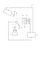
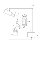
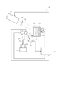
- FIG. 1 is a schematic view of a member manufacturing apparatus according to the first embodiment of the present disclosure.
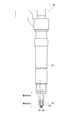
- FIG. 2 is a cross-sectional view of a fuel injection valve including a nozzle body manufactured by a method for manufacturing a member according to the first embodiment of the present disclosure.
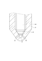
- FIG. 3 is an enlarged cross-sectional view of the nozzle body of FIG.
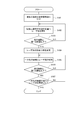
- FIG. 4 is a flowchart of a method of manufacturing a member according to the first embodiment of the present disclosure.
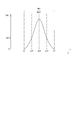
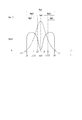
- FIG. 5 is a characteristic diagram showing the intensity distribution of laser light in the member manufacturing method according to the first embodiment of the present disclosure;
- FIG. 1 is a schematic view of a member manufacturing apparatus according to the first embodiment of the present disclosure.
- FIG. 2 is a cross-sectional view of a fuel injection valve including a nozzle body manufactured by a method for manufacturing a member according to the first embodiment of the present disclosure.
- FIG. 3 is an enlarged cross-sectional view of the nozzle body of FIG.
- FIG. 4 is a
- FIG. 6A is a schematic diagram illustrating steps of a method for manufacturing a member according to the first embodiment of the present disclosure
- 6B is a view taken along arrow VIb in FIG. 6A
- FIG. 7 is a characteristic diagram showing the intensity distribution of laser light in the member manufacturing method according to the first embodiment of the present disclosure, and is a characteristic chart showing the intensity distribution of laser light different from FIG.
- FIG. 8A is a schematic diagram illustrating steps of the method for manufacturing a member according to the first embodiment of the present disclosure, and is a schematic diagram illustrating steps different from FIG. 6A
- 8B is a VIIIb arrow view of FIG. 8A
- FIG. 9A is a characteristic diagram showing the intensity distribution of laser light in the method for manufacturing a member according to the second embodiment of the present disclosure
- FIG. 9A is a characteristic diagram showing the intensity distribution of laser light in the method for manufacturing a member according to the second embodiment of the present disclosure
- FIG. 9A is a characteristic diagram showing the intensity distribution of laser light in the method for
- FIG. 9B is a schematic diagram illustrating steps of a method for manufacturing a member according to the second embodiment of the present disclosure.
- FIG. 10 is a flowchart of a method for manufacturing a member according to the third embodiment of the present disclosure;
- FIG. 11A is a schematic diagram illustrating a process of a method for manufacturing a member according to the third embodiment of the present disclosure;
- FIG. 11B is a XIb arrow view of FIG.
- FIG. 12A is a schematic diagram illustrating steps of a method for manufacturing a member according to the third embodiment of the present disclosure, and is a schematic diagram illustrating a state different from FIG. 11A; 12B is a view taken in the direction of arrow XIIb in FIG. FIG.
- FIG. 13 is a schematic view of a member manufacturing apparatus according to the fourth embodiment of the present disclosure.
- FIG. 14 is a schematic diagram of a member manufacturing apparatus according to the fifth embodiment of the present disclosure;
- FIG. 15 is a schematic diagram of a member manufacturing apparatus according to the sixth embodiment of the present disclosure;
- FIG. 16 is a flowchart of a method for manufacturing a member according to the sixth embodiment of the present disclosure;
- FIG. 17 is an enlarged cross-sectional view of a workpiece in the method for manufacturing a member according to the sixth embodiment of the present disclosure;
- FIG. 18 is a schematic diagram of a member manufacturing apparatus according to the seventh embodiment of the present disclosure;
- FIG. 19 is a schematic diagram illustrating steps of a method for manufacturing a member according to the seventh embodiment of the present disclosure.
- FIG. 20 is a schematic diagram illustrating steps of a method for manufacturing a member according to the seventh embodiment of the present disclosure, and is a schematic diagram illustrating steps different from FIG.
- FIG. 21 is a characteristic diagram showing the intensity distribution of laser light in the method for producing a member of a comparative example
- FIG. 22A is a schematic diagram illustrating steps in a method for manufacturing a member of a comparative example
- 22B is a view taken along arrow XXIIb in FIG. 22A.
- the laser processing apparatus 1 as the “member manufacturing apparatus” according to the first embodiment is used for manufacturing the nozzle body 93 as the “member” of the fuel injection valve 90 for diesel fuel shown in FIG.
- the fuel injection valve 90 includes a nozzle body 93, a needle 95 provided so as to be in contact with a valve seat 94 included in the nozzle body 93, and the needle 95 can be driven in the axial direction.
- An electromagnetic drive unit 96 is provided.
- a suck chamber 97 is defined between the needle 95 abutting against the valve seat 94 and the nozzle body 93.
- the nozzle body 93 has a nozzle hole 98 as a “through hole” that communicates the outside of the nozzle body 93 with the sac chamber 97.
- the fuel introduced into the nozzle body 93 is injected to the outside through the sac chamber 97 and the injection hole 98 when the needle 95 is separated from the valve seat 94.
- the laser processing apparatus 1 can form the injection hole 98 in the workpiece 7.
- the laser processing apparatus 1 includes a member holding unit 11, a laser oscillation unit 13, an optical element unit 15, a light detection unit 17, a control unit 19, and the like.
- the locus of the laser beam in the laser processing apparatus 1 is indicated by a dotted line L0 indicating the outer edge of the laser beam. Further, the locus of light from the workpiece 7 is indicated by a dotted line L7.
- the member holding part 11 is formed so as to be able to hold the bottomed cylindrical workpiece 7.
- the member holding unit 11 holds the workpiece 7 so that the laser beam is irradiated from the outside of the workpiece 7.
- the laser oscillation unit 13 oscillates a laser beam capable of forming the injection hole 98 in the workpiece 7.
- the laser oscillation unit 13 is electrically connected to the control unit 19.
- the laser oscillation unit 13 oscillates laser light based on a command signal output from the control unit 19.
- the laser light oscillated by the laser oscillation unit 13 becomes collimated light adjusted in a parallel state by passing through a collimating lens 141 provided between the laser oscillation unit 13 and the optical element unit 15.
- the collimated light reaches the optical element unit 15.
- the optical element unit 15 is a so-called reflective liquid crystal panel, and includes a front glass 151, a liquid crystal layer 152, a back reflector 153, an electrode 154 electrically connected to the control unit 19, and the like.
- collimated light that has entered the optical element unit 15 through the front glass 151 is reflected by the back reflector 153 in a predetermined direction.
- the alignment direction of the liquid crystal molecules included in the liquid crystal layer 152 is changed by a voltage applied to the electrode 154.
- the optical element unit 15 can modulate the spatial light phase of the laser light from the optical element unit 15 toward the workpiece 7.
- Laser light traveling from the optical element portion 15 toward the workpiece 7 is condensed by passing through a condenser lens 142 provided between the optical element portion 15 and the workpiece 7, and the desired light of the workpiece 7 is obtained.
- the position is irradiated.
- the light detection unit 17 is electrically connected to the control unit 19.
- the light detection unit 17 is provided outside the workpiece 7 and in the vicinity of a portion where the nozzle hole 98 of the workpiece 7 is processed.
- the light detection unit 17 can receive the reflected light of the laser beam reflected by the outer wall surface of the processed member 7 and the plasma light of fine particles generated from the processed member 7 by processing with the laser light.
- the light detection unit 17 sets the wavelength range of light that can be detected to 200 to 1200 nm so that the plasma light generated when the fine particles of the workpiece 7 react with the laser light can be detected. Has been.
- the light detection unit 17 outputs an electrical signal corresponding to the received intensity to the control unit 19.
- the control unit 19 is electrically connected to the laser oscillation unit 13, the optical element unit 15, and the light detection unit 17.
- the control unit 19 controls the laser oscillation unit 13 and the optical element unit 15 according to the electrical signal output from the light detection unit 17.
- FIG. 4 shows a flowchart of a method for processing the workpiece 7.
- step (hereinafter simply referred to as “S”) 101 the workpiece 7 is set in the member holding portion 11.
- a desired position of the workpiece 7 is irradiated with laser light.
- the desired position is a substantially central position of the nozzle hole 98 of the nozzle body 93 when the workpiece 7 is processed into the nozzle body 93.
- FIG. 5 shows the intensity distribution in the direction perpendicular to the direction in which the laser beam travels with respect to the laser beam irradiated to the workpiece 7 through the condenser lens 142.
- the horizontal axis indicates the distance L from the center cL0 of the laser beam.
- the vertical axis indicates the intensity SoL of the laser beam.
- the workpiece 7 is irradiated with laser light having a beam diameter twice as long as the distance L1, as shown in FIG.
- a region where the laser beam has an intensity greater than 0 is defined as a laser irradiation region Rm1. That is, the shape of the laser irradiation region Rm1 is a substantially circular shape with the distance L1 as a radius.
- the laser light applied to the workpiece 7 in S102 has the strongest intensity at the center cL0 of the laser light, and the intensity decreases as the distance from the center cL0 increases.
- the region up to the distance L21 from the center cL0 can process the workpiece 7.
- the processable region Rm21 is located at the approximate center of the laser irradiation region Rm1.
- control unit 19 controls the optical element unit 15 to irradiate the workpiece 7 with laser light having an intensity distribution as shown in FIG.
- a voltage is applied to the electrode 154, and the liquid crystal layer 152 is operated so that the laser beam oscillated by the laser oscillation unit 13 becomes a laser beam having an intensity distribution as shown in FIG.
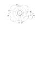
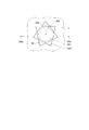
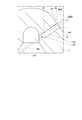
- FIG. 6A shows an enlarged cross-sectional view of a portion of the workpiece 7 that is irradiated with laser light.
- the direction in which the laser beam travels is indicated by a solid arrow Ld1.
- FIG. 6B shows a view taken along the arrow VIb in FIG. 6A.
- the outer edge of the laser irradiation region Rm1 defined in FIG. 5 is indicated by a one-dot chain line Lw1.
- the outer edge of the workable region Rm21 defined in FIG. 5 is indicated by a two-dot chain line Lw2.
- the laser beam whose intensity distribution is as shown in FIG. 5 is applied to the approximate center of the nozzle hole 98 scheduled to be processed into the workpiece 7 as shown in FIG. 6B.
- the inner diameter of the primary hole 981 as the lower hole of the injection hole 98 processed by the laser beam having the intensity distribution shown in FIG. 5 is smaller than the inner diameter of the injection hole 98 indicated by the dotted line in FIGS. 6A and 6B.
- the laser light in the region other than the workable region Rm21 in the laser irradiation region Rm1 does not have an intensity capable of processing the member 7 to be processed, so that the outer wall is not damaged.
- the primary hole 981 is shape
- FIG. 6A and 6B the primary hole 981 is shape
- the light detection unit 17 receives reflected light or plasma light from the member 7 to be processed.
- the light detection unit 17 outputs an electrical signal corresponding to the intensity of the received light to the control unit 19.
- the intensity determination step it is determined whether or not the intensity of the reflected light or plasma light from the workpiece 7 is equal to or less than a first threshold as a “predetermined threshold”.
- a first threshold as a “predetermined threshold”.
- the control unit 19 determines whether or not the intensity of the reflected light or plasma light from the workpiece 7 received by the light detection unit 17 is equal to or less than a preset first threshold value. If it is determined that the intensity of the light received by the light detection unit 17 is equal to or less than the first threshold, the process proceeds to S104. If it is determined that the intensity of the light received by the light detection unit 17 is equal to or higher than the first threshold value, the process returns to S102, and the laser beam having the intensity distribution shown in FIG.
- the laser Change the light intensity distribution the intensity distribution of the laser beam changed in S104 will be described with reference to FIG.
- FIG. 7 shows the intensity distribution in the direction perpendicular to the direction in which the laser beam travels with respect to the laser beam irradiated to the workpiece 7 through the condenser lens 142.
- the horizontal axis indicates the distance L from the center cL0 of the laser beam.
- the vertical axis indicates the intensity SoL of the laser beam.
- the intensity distribution of the laser light changed in S104 is indicated by a solid line AL1
- the intensity distribution of the laser light obtained by forming the primary hole 981 in S102 is indicated by a two-dot chain line VL1.
- the laser beam modulated in S104 has a beam diameter twice as long as the distance L1, but has the strongest intensity at a position different from the center cL0 of the laser beam.
- the laser beam has the strongest intensity in the outer edge region Rm3 that is separated from the center cL0 within the beam diameter of the laser beam by a distance (L1 / 2). That is, the spatial distribution of the laser light is modulated such that the energy in the central region Rm4 closer to the distance (L1 / 2) from the center cL0 is smaller than the energy in the outer edge region Rm3.
- the control unit 19 controls the optical element unit 15 so as to irradiate the workpiece 7 with laser light having a spatial distribution as shown in FIG.
- a voltage is applied to the electrode 154, and the liquid crystal layer 152 is operated so that the laser beam oscillated by the laser oscillation unit 13 becomes a laser beam having an intensity distribution as shown in FIG.
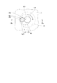
- FIG. 8A shows an enlarged cross-sectional view of a portion of the workpiece 7 that is irradiated with laser light.
- FIG. 8B shows a view taken along the line VIIIb of FIG. 8A.
- the laser light having the intensity distribution shown in FIG. 7 is applied to the outer wall of the workpiece 7 so that the edge 982 is irradiated with the laser light in the processable region Rm21, as shown in FIG. 8B.
- the edge 982 is processed by the laser beam, and an enlarged hole 983 communicating with the primary hole 981 is formed in the radially outward direction of the primary hole 981.
- a part of the laser beam in the laser irradiation region Rm1 excluding the workable region Rm21 enters the inside of the workpiece 7 through the already penetrated primary hole 981. .
- the laser beam in the region other than the workable region Rm21 in the laser irradiation region Rm1 does not have an intensity capable of processing the workpiece 7, the inner wall surface of the workpiece 7 is not damaged.
- the processable region Rm21 is moved by moving the focal position of the laser light along the circumferential direction of the primary hole 981, as indicated by the solid line arrow Ld2 in FIG. 8B.
- the enlarged hole 983 is formed so as to surround the radially outward direction of the primary hole 981.
- S106 it is determined whether or not the light intensity is equal to or less than a second threshold value.
- the control unit 19 determines whether or not the intensity of reflected light or plasma light from the workpiece 7 received by the light detection unit 17 is equal to or lower than a preset second threshold value. . That is, it can be seen whether or not the enlarged hole 983 has penetrated due to a change in the intensity of reflected light or plasma light.
- the process proceeds to S107. If it is determined that the intensity of the light received by the light detection unit 17 is greater than or equal to the second threshold value, the process returns to S105, and laser light having the intensity distribution shown in FIG.
- the laser light having the intensity distribution shown in FIG. determines whether or not all of the edge 982 has been irradiated. The control unit 19 determines whether or not the edge 982 has been irradiated with all the laser light having the intensity distribution shown in FIG. 7 based on a program input in advance. If the control unit 19 determines that the laser beam has been applied to all of the edge 982, the current routine is terminated.
- the process returns to S105, and the laser beam having the intensity distribution shown in FIG. 7 is applied to the edge 982 where the enlarged hole 983 is not processed. Irradiate.
- the nozzle hole 98 is manufactured in the workpiece 7 in this way, and the nozzle body 93 is manufactured.
- the laser beam that has processed the nozzle hole passes through the penetrating nozzle hole and enters the workpiece. Since the laser beam entering the workpiece is irradiated onto the inner wall surface of the workpiece positioned in the laser beam irradiation direction, the inner wall surface of the workpiece may be damaged.
- the detail of the processing method of the to-be-processed member of a comparative example is demonstrated based on FIG.21,22A, 22B.
- the primary hole 981 is formed using a laser beam having a beam diameter twice as long as the distance L1 as in the present embodiment.
- the enlarged hole 983 is formed by irradiating the edge 982 of the primary hole 981 with laser light.
- the intensity distribution of the laser beam when forming the enlarged hole 983 is not changed from the intensity distribution of the laser beam when forming the primary hole 981. That is, as shown in FIG.
- the laser beam used in the method for processing a member to be processed of the comparative example has the strongest intensity at the center cL1 of the laser beam, and the intensity decreases as the distance from the center cL1 increases.
- the region up to the distance L20 from the center cL1 becomes a processable region Rm20 that is a region having energy capable of processing the workpiece 7.
- the processable region Rm20 is located approximately at the center of the laser irradiation region Rm1.
- the diameter of the processable region Rm20 is the same as the diameter of the primary hole 981.
- FIG. 22A and 22B show the state of processing of the workpiece 7 when the enlarged hole 983 is formed in the processing method of the workpiece of the comparative example.
- FIG. 22A shows an enlarged cross-sectional view of a portion of the workpiece 7 that is irradiated with laser light.
- FIG. 22B shows a view taken along arrow XXIIb in FIG. 22A. 22A and 22B, the outer edge of the workable region Rm20 defined in FIG. 21 is indicated by a two-dot chain line Lw3.
- the workpiece 7 is irradiated with laser light so that the edge 982 of the primary hole 981 is irradiated with the laser light in the workable region Rm20.
- laser light in a part of the region Rm0 of the workable region Rm20 that is not used for processing the edge portion 982 enters the workpiece 7 through the primary hole 981.
- the intensity of light from the workpiece 7 received by the light detection unit 17 is higher than that before the primary hole 981 penetrates. Get smaller. Therefore, when it is determined that the intensity of the light detected by the light detection unit 17 is equal to or less than the first threshold, the laser that the laser oscillation unit 13 oscillates so that the intensity of the outer edge region Rm3 is larger than the intensity of the central region Rm4. Modulates the spatial light phase of light. Next, the edge 982 is irradiated with laser light whose spatial light phase is modulated, and an enlarged hole 983 communicating with the primary hole 981 is formed.
- the laser light that reaches the inside of the workpiece 7 through the primary hole 981 is a laser beam in a region excluding the workable region Rm21 in the laser irradiation region Rm1, and therefore, on the inner wall surface of the workpiece 7 Even if irradiated, the workpiece 7 is not damaged. Thereby, damage to the inner wall surface of the workpiece 7 can be prevented by the laser light passing through the primary hole 981 and the enlarged hole 983.
- the inner wall surface of the workpiece 7 can be prevented from being damaged by the laser beam passing through the primary hole 981, and therefore the workpiece is affected by the laser that has reached the inside of the workpiece 7. There may be no laser shielding member for preventing damage to the inner wall surface 7. Thereby, the manufacturing cost of the nozzle body 93 can be reduced. Further, when the nozzle hole 98 is processed, the number of steps for inserting or extracting the laser shielding member can be reduced.
- the optical element unit 15 is provided so that the focal position can be changed by modulating the spatial light phase of the laser light. Accordingly, it is possible to prevent positional deviation when the enlarged hole 983 is formed, as compared with the case where a configuration that requires driving such as a rotator or a galvano scanner is used to change the focal position of the laser beam. Therefore, the nozzle hole 98 can be formed with high accuracy.
- the laser processing apparatus 1 of the present embodiment controls the intensity distribution of the laser light based on the detection result of the light detection unit 17 when the primary hole 981 and the enlarged hole 983 penetrate.
- the light detection unit 17 is provided so as to be capable of receiving the plasma light of the fine particles generated from the workpiece 7 by processing with laser light. Thereby, it is easier to determine that the primary hole 981 and the enlarged hole 983 have penetrated than the reflected light of the laser beam reflected by the outer wall surface of the processed member 7 that may change depending on the shape of the processed member 7. Therefore, the primary hole 981 and the enlarged hole 983 can be reliably penetrated.
- the second embodiment differs from the first embodiment in the intensity distribution of the laser light when forming the enlarged hole.
- symbol is attached
- FIG. 9A shows the intensity distribution in the direction perpendicular to the direction in which the laser beam travels with respect to the laser beam irradiated to the workpiece 7 through the condenser lens 142.
- the horizontal axis indicates the distance L from the center cL0 of the laser beam.
- the vertical axis indicates the intensity SoL of the laser beam.
- the spatial distribution of the laser light when forming the enlarged hole 983 in this embodiment is modulated so that the intensity of the central region Rm4 is smaller than the intensity of the outer edge region Rm3.
- the laser light is modulated so that the processable region Rm21 between the distance L5 and the distance L6 is provided at two locations of the outer edge region Rm3.
- the two processable regions Rm21 are located at positions shifted from the center of the laser irradiation region Rm1.
- a voltage is applied to the electrode 154, and the liquid crystal layer 152 is operated so that the laser beam oscillated by the laser oscillation unit 13 becomes a laser beam having an intensity distribution as shown in FIG. 9A.
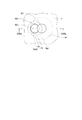
- FIG. 9B shows a state of processing of the workpiece 7 when the enlarged hole 983 is formed by the laser beam having the intensity distribution shown in FIG. 9A.
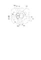
- FIG. 9B is a schematic view of the primary hole 981 and the enlarged hole 983 as seen from the direction in which the laser beam is irradiated.
- FIG. 9B shows a cross-sectional line of the laser beam having the intensity distribution shown in FIG. 9A as an IXa-IXa line.
- the edge 982 of the primary hole 981 is irradiated with laser light having the intensity distribution of FIG. 9A
- two enlarged holes 983 can be simultaneously formed in the edge 982.
- molds the enlarged hole 983 can be shortened. Therefore, the second embodiment has the same effect as the first embodiment, and can further reduce the man-hours required for manufacturing the nozzle body 93.
- FIGS. 10, 11A, 11B, 12A, and 12B a member manufacturing apparatus and a member manufacturing method according to the third embodiment of the present disclosure will be described based on FIGS. 10, 11A, 11B, 12A, and 12B.
- the third embodiment differs from the first embodiment in the action of the optical element portion.
- symbol is attached
- the optical element unit 15 included in the laser processing apparatus according to the third embodiment modulates the spatial light phase of the laser light traveling from the optical element unit 15 toward the workpiece 7 by changing the alignment direction of the liquid crystal molecules in the liquid crystal layer 152. It is possible to change the spread angle of the laser beam.
- FIG. 10 shows a flowchart of a method for processing the workpiece 7.
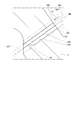
- FIG. 11A and FIG. 12A show enlarged cross-sectional views of a portion of the workpiece 7 that is irradiated with laser light.
- FIG. 11B and FIG. 12B the XIb arrow directional view of FIG. 11A and the XIIb arrow directional view of FIG. 12A are shown.
- the injection hole 98 in which the cross-sectional shape of the inner wall surface of the injection hole 98 is not linear on the plane including the central axis C981 of the primary hole 981 can be formed.
- the injection hole 98 formed by the processing method of the workpiece 7 according to the present embodiment has a cross-sectional area at the approximate center of the injection hole 98 as shown in FIGS. 11A, 11B, 12A, and 12B. It is formed so as to be smaller than the cross-sectional area of the inner opening 984 and the cross-sectional area of the outer opening 985. At this time, the cross-sectional area of the inner opening 984 and the cross-sectional area of the outer opening 985 may be different or the same.
- the workpiece 7 is set in the member holding part 11 in the same manner as in S101 of the first embodiment.
- the laser beam for forming the primary hole 981 is irradiated to a desired position of the workpiece 7 as in S102 of the first embodiment.
- S203 it is determined whether or not the intensity of light from the workpiece 7 is equal to or lower than the first threshold value, as in S103 of the first embodiment.
- the optical element unit 15 Change the spread angle.
- S ⁇ b> 205 as the “secondary forming step”
- the primary hole 981 or the inner wall surface 986 of the injection hole 98 in which the primary hole 981 is partially processed is irradiated with laser light.
- the laser beam is incident on the primary hole 981 in a state where the center cL0 of the laser beam is inclined with respect to the central axis C981 of the primary hole 981.
- FIGS. 11A and 11B show a state of processing of the workpiece 7 by a laser beam having a relatively small divergence angle
- FIGS. 12A and 12B show a state of processing of the member 7 by a laser beam having a relatively small divergence angle.
- the laser beam is a relatively high energy laser beam that is dominant in reflection compared to absorption in relation to the irradiated inner wall surface 986.
- the inner wall surface 986 is in a non-parallel state with respect to the central axis C981.
- the laser light incident on the primary hole 981 or the nozzle hole 98 being processed is reflected by the inner wall surface 986 and then travels toward the inside of the workpiece 7.
- the reflected laser beam is condensed on the edge portion 987 as “a predetermined portion of the member” of the inner opening 984 so that the shape of the inner opening 984 becomes a desired shape. Is processed.
- the spread angle SA31 of the laser beam is relatively small, the laser beam reflected by the inner wall surface 986 has a relatively large beam diameter L31 in the vicinity of the edge 987 of the inner opening 984.
- the processing amount per unit time of the edge portion 987 increases. Thereby, for example, as shown in a region A31 in FIG. 11B, a portion having a relatively large inner diameter R31 is formed.
- the area of the reflection surface on the inner wall surface 986 of the laser beam having the spread angle SA31 and the area of the reflection surface on the inner wall surface 986 of the laser beam having the spread angle SA32 are the same size. Since the energy of the laser beam is constant regardless of the spread angle, the energy per unit area of the laser beam irradiated on the reflecting surface on the inner wall surface 986 is the same.
- the inner opening 984 is processed by irradiating the edge 987 of the inner opening 984 with the laser beam reflected by the inner wall surface 986.
- the amount of processing per unit time at the edge 987 of the inner opening 984 is changed by changing the spread angle of the laser light incident on the primary hole 981 or the injection hole 98 being processed.
- the laser light necessary for processing the inner opening 984 is incident on the primary hole 981 or the injection hole 98 in the middle of processing, so that the laser light that has not been used for processing is difficult to be irradiated on the inner wall surface of the workpiece 7. .
- 3rd embodiment has (1), (2), (4), (5) of 1st embodiment.
- the inner opening 984 having a desired shape as shown in FIGS. 11B and 12B can be formed without being affected by the shape of the outer opening 985. Can be processed. As described above, in this embodiment, the number of places that can be machined inside the outer opening 985 can be increased, so that the degree of freedom of the shape of the nozzle hole 98 can be improved.
- FIG. 13 shows a schematic diagram of the laser processing apparatus 2 according to the present embodiment.
- the laser processing apparatus 2 includes a member holding unit 11, a laser oscillation unit 13, an optical element unit 25, a light detection unit 17, a control unit 19, and the like.
- the locus of the laser beam in the laser processing apparatus 2 is indicated by a dotted line L0 indicating the outer edge portion of the laser beam. Further, the locus of light from the workpiece 7 is indicated by a dotted line L7.
- the optical element unit 25 includes a front glass 151, a plurality of diffraction lenses 252, a back reflector 153, a drive unit 254 that is electrically connected to the control unit 19, and the like.
- the diffraction lens 252 is rotated by the driving unit 254. Thereby, it is possible to change the light diffraction pattern of the laser beam from the optical element portion 25 toward the workpiece 7.
- Laser light traveling from the optical element unit 25 toward the workpiece 7 is irradiated to a desired position of the workpiece 7 through the condenser lens 142.
- the spatial light phase of the laser light can be modulated by a combination of the plurality of diffraction lenses 252.
- 4th embodiment has the same effect as 1st embodiment.
- the fifth embodiment differs from the first embodiment in the number of light detection units.
- symbol is attached
- FIG. 14 shows a schematic diagram of the laser processing apparatus 3 according to the present embodiment.
- the laser processing apparatus 3 includes a member holding unit 11, a laser oscillation unit 13, an optical element unit 15, a plurality of light detection units 17, a control unit 19, and the like.
- the locus of the laser beam in the laser processing apparatus 3 is indicated by a dotted line L0 indicating the outer edge portion of the laser beam. Further, the locus of light from the workpiece 7 is indicated by a dotted line L7.
- the plurality of light detection units 17 are positioned at various angles with respect to the workpiece 7. Thereby, in the processing method of the member 7 to be processed according to the present embodiment, whether the primary hole 981 and the enlarged hole 983 have penetrated through comprehensive judgment from changes in reflected light of the laser detected by the plurality of light detection units 17. It can be determined whether or not. Therefore, the fifth embodiment has the same effect as the first embodiment and can form the injection hole 98 with high accuracy.
- the sixth embodiment is different from the first embodiment in that a laser shielding member is provided.
- symbol is attached
- FIG. 15 shows a schematic diagram of the laser processing apparatus 4 according to the present embodiment.
- the laser processing device 4 includes a member holding unit 11, a laser shielding member 12, a laser oscillation unit 13, an optical element unit 15, a light detection unit 17, a control unit 19, and the like.
- the locus of the laser beam in the laser processing apparatus 4 is indicated by a dotted line L0 indicating the outer edge of the laser beam. Further, the locus of light from the workpiece 7 is indicated by a dotted line L7.
- the laser shielding member 12 is supported by the support portion 121 and is provided so as to be insertable inside the workpiece 7.
- the support part 121 can rotate the laser shielding member 12 inside the workpiece 7.
- FIG. 16 shows a flowchart of a method for processing the workpiece 7.
- the workpiece 7 is set in the member holding unit 11 as in S ⁇ b> 101 of the first embodiment.
- the laser shielding member 12 is inserted inside the workpiece 7 in S302 as a “member installation step”.
- the laser shielding member 12 is provided at a position where the laser light passing through the primary hole 981 and the enlarged hole 983 through which the outer wall surface 122 passes is irradiated. It is done.
- the laser beam for forming the primary hole 981 is irradiated to a desired position of the workpiece 7 in the same manner as in S102 of the first embodiment.
- S304 it is determined whether or not the intensity of light from the workpiece 7 is equal to or lower than the first threshold value, as in S103 of the first embodiment.
- the intensity distribution of the laser beam is changed.
- the outer wall surface 122 of the laser shielding member 12 is irradiated. Thereby, the laser beam is not irradiated on the inner wall surface 71 of the workpiece 7 that faces the outer wall surface 123 opposite to the outer wall surface 122 of the laser shielding member 12.
- the laser beam for forming the enlarged hole 983 is irradiated to the edge portion 982 that forms the primary hole 981 as in S105 of the first embodiment.
- S306 in S307, as in S106 of the first embodiment, it is determined whether or not the light intensity is equal to or less than the second threshold value.
- S308 in S107 of the first embodiment, the laser light is edged.
- the control unit 19 determines whether or not the portion 982 has been completely irradiated.
- the nozzle hole 98 is manufactured in the workpiece 7 in this way, and the nozzle body 93 is manufactured.
- the laser processing apparatus 4 includes a laser shielding member 12 that is irradiated with laser light that passes through the primary hole 981 and the enlarged hole 983 that pass therethrough. Thereby, it is possible to reliably prevent the laser beam entering the inside of the workpiece 7 from being irradiated on the inner wall surface 71 of the workpiece 7 immediately after the primary hole 981 penetrates or immediately after the enlarged hole 983 penetrates. it can. Therefore, the sixth embodiment has the effects (1), (3) to (5) of the first embodiment, and can reliably prevent damage to the inner wall surface of the workpiece 7 due to the laser beam.
- FIG. 18 shows a schematic diagram of the laser processing apparatus 5 according to the present embodiment.
- the laser processing apparatus 5 includes a member holding unit 31, a laser oscillation unit 13, an optical element unit 35, a light detection unit 17, a control unit 19, and the like.
- the laser processing apparatus 5 can form a plurality of through holes 88 in the substantially disk-shaped workpiece 8.
- the locus of the laser beam in the laser processing apparatus 5 is indicated by a dotted line L0 indicating the outer edge portion of the laser beam. Further, the locus of light from the workpiece 8 is indicated by a dotted line L8.
- the member holding portion 31 can hold the workpiece 8 so as not to move relative to the optical element portion 35.
- the optical element unit 35 is a so-called reflective liquid crystal panel, and includes a front glass 151, a liquid crystal layer 36, a back reflector 153, a plurality of electrodes 371, 372, 373, and 374.
- the liquid crystal layer 36 includes a plurality of liquid crystal molecules 361, 362, 363, and 364 (see FIGS. 19 and 20).
- the alignment direction of the liquid crystal molecules 361, 362, 363, 364 is individually changed depending on the voltage applied to the electrodes 371, 372, 373, 374 corresponding to the liquid crystal molecules 361, 362, 363, 364, respectively. To do.
- a method for processing the workpiece 8 in this embodiment will be described with reference to FIGS.
- the spatial light phase of the laser beam irradiated on the workpiece 8 is modulated by controlling the alignment direction of the liquid crystal molecules 361, 362, 363, 364, and the focal position of the laser beam is changed. change.
- a through hole 881 which is one of the through holes 88, is formed on the outer edge portion at a distant position.
- the through-hole 881 is formed by forming a primary hole and then forming an enlarged hole at the edge that forms the primary hole.
- the through-hole 881 After forming the through-hole 881, a part of the laser beam reflected by the back reflector 153 is shielded by the liquid crystal molecules 364 as shown in FIG. As a result, the laser light passing through the condenser lens 142 is focused on the outer edge portion of the outer edge portion of the workpiece 8 that is close to the base 311, so that the laser light is directed to the outer edge portion near the base 311.
- a through hole 882 which is one of the through holes 88 is formed. As in the first embodiment, the through-hole 882 is formed by forming a primary hole and then forming an enlarged hole at the edge that forms the primary hole.
- an enlarged hole is formed using a laser beam having an intensity of a workable region in the outer edge region.
- the focal position of the laser light can be changed by changing the arrangement of the plurality of liquid crystal molecules in the optical element unit 35.
- the several through-hole 88 can be shape
- the arrangement direction of the plurality of liquid crystal molecules in the optical element unit 15 is electrically controlled in order to change the focal position of the laser beam.
- the through-hole 88 can be shape
- the “member” is the nozzle body of the fuel injection valve.
- the “member” is not limited to this. What is necessary is just to have a "through-hole”.
- the laser beam when forming the enlarged hole, is assumed to be located in the outer edge region.
- the region where the workable region is located is not limited to this.
- the laser beam in the workable region does not have to reach the side opposite to the side of the workpiece to be irradiated with the laser beam through the primary hole that has passed through.
- the light detection unit can receive reflected light and plasma holes.
- the optical element unit has a liquid crystal layer or a diffractive lens.
- the configuration of the optical element unit is not limited to this. Any configuration capable of modulating the spatial light phase of the laser light entering the optical element portion may be used.
- a plurality of nozzle holes may be formed by changing the focal position of the laser beam as in the seventh embodiment.
- the laser beam has two workable areas in the outer edge area.
- the number of processable areas is not limited to this. There may be more than two locations.
- the spread angle of the laser beam is changed by modulating the spatial light phase of the laser beam in the optical element section.
- the method for changing the spread angle of the laser light is not limited to this.
- the spread angle of the laser beam may be changed by changing the position of the condenser lens with respect to the workpiece.
- the intensity distribution of the laser beam may be changed as in the first and second embodiments.
- the laser beam is preferably a relatively high energy laser beam.
- the energy of the laser beam is not limited to this.
- a relatively low energy laser beam may be used.
- the beam diameter near the edge of the inner opening is relatively large, and when the spread angle of the laser beam is large, the beam diameter near the edge of the inner opening is relatively small. It became.
- the relationship between the divergence angle and the beam diameter in the vicinity of the edge of the inner opening is not limited to this.
- the beam diameter near the edge of the inner opening is relatively small when the laser beam spread angle is small, and the inner side when the laser beam spread angle is large.
- the beam diameter in the vicinity of the edge of the opening may be relatively large.
- only the processing of the edge portion of the inner opening has been described. However, the inner wall surface of the nozzle hole may be processed while changing the processing amount per unit time by changing the spread angle of the laser beam. .
- the edge of the inner opening is processed by the reflection of the laser beam on the inner wall surface of the nozzle hole that is not parallel to the central axis of the primary hole.
- the inner wall surface of the nozzle hole that reflects the laser beam may be parallel to the central axis of the primary hole.
- the area of the reflection surface on the inner wall surface of the nozzle hole of the laser beam having a different divergence angle is assumed to be the same.
- the area of the reflective surface may be different.
- a plurality of light detection units may be provided as in the fifth embodiment. Moreover, you may provide a laser shielding member like 6th embodiment.
- a laser shielding member may be provided as in the sixth embodiment.
- a laser shielding member may be provided between the workpiece and the member holding portion as in the sixth embodiment.
Landscapes
- Physics & Mathematics (AREA)
- Optics & Photonics (AREA)
- Engineering & Computer Science (AREA)
- Plasma & Fusion (AREA)
- Mechanical Engineering (AREA)
- Laser Beam Processing (AREA)
Abstract
通孔(88、98)を有する部材(93)の製造方法であって、一次成形工程、強度判定工程、レーザ変調工程、及び、二次成形工程を含む。一次成形工程では、レーザ光を被加工部材(7、8)に照射し、光検出部(17)によって被加工部材からの光を受光しつつ通孔に比べ内径が小さい一次孔(981)を被加工部材に成形する。強度判定工程では、光検出部が検出する光の強度が所定の閾値以下であるか否かを判定する。強度判定工程において光検出部が検出する光の強度が所定の閾値以下であると判定されると、レーザ変調工程では、被加工部材に照射されるレーザ光の空間光位相を変調する。二次成形工程では、空間光位相が変調されたレーザ光を一次孔の縁部に照射し、通孔を成形する。
Description
本出願は、2016年1月27日に出願された特許出願番号2016-013075号および2017年1月12日に出願された特許出願番号2017-003462号に基づくものであり、ここにその記載内容を援用する。
本開示は、部材の製造方法、及び、部材の製造装置に関する。
従来、レーザ光を用いた通孔を有する部材の製造方法が知られている。当該部材の製造方法では、通孔が貫通したとき通孔を通って被加工部材のレーザ光を照射する側とは反対側に抜けるレーザ光が被加工部材のレーザ光を照射する側とは反対側にある物を損傷することを防止するために、被加工部材のレーザ光を照射する側とは反対側にレーザ光を遮蔽可能なレーザ遮蔽部材を設ける。例えば、特許文献1には、レーザ光を用いて燃料噴射弁の噴孔を加工するとき、ノズルボディとなる被加工部材内にコランダムや立方晶ジルコニアなどの高融点材料から形成されるレーザ遮蔽部材を挿入する部材の製造方法が記載されている。
特許文献1に記載の部材の製造方法では、レーザ遮蔽部材は、レーザ光が照射されると徐々に損傷するため、ある程度の頻度で交換する必要がある。このため、レーザ光による被加工部材の加工工程においてはレーザ遮蔽部材を交換するための工数が必要となる。また、特許文献1の部材の製造方法では、レーザ遮蔽部材は、レーザ光による損傷の度合いを抑えるため、比較的高価な材料から形成されている。上述したように、レーザ遮蔽部材はある程度の頻度で交換されるため、部材の製造にかかるコストが増大する。
本開示の目的は、通孔を成形するレーザ光が被加工部材を損傷することを防止する部材の製造方法を提供することである。
本開示の第一態様による部材の製造方法は、一次成形工程、強度判定工程、レーザ変調工程、及び、二次成形工程を含む。
一次成形工程では、レーザ光を被加工部材に照射し、光検出部によって被加工部材からの光を受光しつつ通孔に比べ内径が小さい一次孔を被加工部材に成形する。
強度判定工程は、光検出部が検出する光の強度が所定の閾値以下であるか否かを判定する。
レーザ変調工程は、光検出部が検出する光の強度が所定の閾値以下であると判定されると、被加工部材に照射されるレーザ光の空間光位相を変調する。
二次成形工程は、空間光位相が変調されたレーザ光を一次孔の縁部に照射し、通孔を形成する。
一次成形工程では、レーザ光を被加工部材に照射し、光検出部によって被加工部材からの光を受光しつつ通孔に比べ内径が小さい一次孔を被加工部材に成形する。
強度判定工程は、光検出部が検出する光の強度が所定の閾値以下であるか否かを判定する。
レーザ変調工程は、光検出部が検出する光の強度が所定の閾値以下であると判定されると、被加工部材に照射されるレーザ光の空間光位相を変調する。
二次成形工程は、空間光位相が変調されたレーザ光を一次孔の縁部に照射し、通孔を形成する。
本開示の部材の製造方法では、一次成形工程において、レーザ光を用いて通孔に比べ内径が小さい一次孔を被加工部材に成形する。一次孔が貫通すると、光検出部が受光する光の強度は、一次孔が貫通する前に比べ小さくなる。そこで、強度判定工程において、光検出部が検出する光の強度が所定の閾値以下であると判定されると、レーザ変調工程において被加工部材に照射されるレーザ光の空間光位相を変調する。このとき、レーザ変調工程では、レーザ光の空間光位相を変調することによって、一次孔の縁部を加工するときに既に貫通している一次孔を通るレーザ光の強度を比較的小さくしたり、部材の単位時間当たりの加工量が少なくなるようレーザ光の広がり角を変更したりする。これにより、一次孔を通って被加工部材の内部に侵入するレーザは、エネルギが小さくなっているため、貫通した一次孔を通るレーザ光によって被加工部材や被加工部材のレーザ光が照射される側とは反対側にある物が損傷することを防止することができる。
本開示についての上記目的及びその他の目的、特徴や利点は、添付の図面を参照しながら下記の詳細な技術により、より明確になる。その図面は、
図1は、本開示の第一実施形態による部材の製造装置の模式図であり、
図2は、本開示の第一実施形態による部材の製造方法によって製造されるノズルボディを備える燃料噴射弁の断面図であり、
図3は、図2のノズルボディの拡大断面図であり、
図4は、本開示の第一実施形態による部材の製造方法のフローチャートであり、
図5は、本開示の第一実施形態による部材の製造方法におけるレーザ光の強度分布を示す特性図であり、
図6Aは、本開示の第一実施形態による部材の製造方法の工程を説明する模式図であり、
図6Bは、図6AのVIb矢視図であり、
図7は、本開示の第一実施形態による部材の製造方法におけるレーザ光の強度分布を示す特性図であって、図5とは異なるレーザ光の強度分布を示す特性図であり、
図8Aは、本開示の第一実施形態による部材の製造方法の工程を説明する模式図であって、図6Aとは異なる工程を説明する模式図であり、
図8Bは、図8AのVIIIb矢視図であり、
図9Aは、本開示の第二実施形態による部材の製造方法におけるレーザ光の強度分布を示す特性図であり、
図9Bは、本開示の第二実施形態による部材の製造方法の工程を説明する模式図であり、
図10は、本開示の第三実施形態による部材の製造方法のフローチャートであり、
図11Aは、本開示の第三実施形態による部材の製造方法の工程を説明する模式図であり、
図11Bは、図11AのXIb矢視図であり、
図12Aは、本開示の第三実施形態による部材の製造方法の工程を説明する模式図であて、図11Aとは異なる状態を説明する模式図であり、
図12Bは、図12AのXIIb矢視図であり、
図13は、本開示の第四実施形態による部材の製造装置の模式図であり、
図14は、本開示の第五実施形態による部材の製造装置の模式図であり、
図15は、本開示の第六実施形態による部材の製造装置の模式図であり、
図16は、本開示の第六実施形態による部材の製造方法のフローチャートであり、
図17は、本開示の第六実施形態による部材の製造方法における被加工部材の拡大断面図であり、
図18は、本開示の第七実施形態による部材の製造装置の模式図であり、
図19は、本開示の第七実施形態による部材の製造方法の工程を説明する模式図であり、
図20は、本開示の第七実施形態による部材の製造方法の工程を説明する模式図であって、図19とは異なる工程を説明する模式図であり、
図21は、比較例の部材の製造方法におけるレーザ光の強度分布を示す特性図であり、
図22Aは、比較例の部材の製造方法における工程を説明する模式図であり、
図22Bは、図22AのXXIIb矢視図である。
以下、本開示の複数の実施形態を図面に基づき説明する。
(第一実施形態)
第一実施形態による「部材の製造装置」としてのレーザ加工装置1は、図2に示すディーゼル燃料用の燃料噴射弁90の「部材」としてのノズルボディ93の製造に用いる。
(第一実施形態)
第一実施形態による「部材の製造装置」としてのレーザ加工装置1は、図2に示すディーゼル燃料用の燃料噴射弁90の「部材」としてのノズルボディ93の製造に用いる。
最初に、燃料噴射弁90の構成を説明する。燃料噴射弁90は、図2、3に示すように、ノズルボディ93、ノズルボディ93が有する弁座94に当接可能に設けられているニードル95、及び、ニードル95を軸方向へ駆動可能な電磁駆動部96を備えている。
弁座94に当接しているニードル95とノズルボディ93との間には、サック室97が区画形成される。ノズルボディ93は、ノズルボディ93の外部とサック室97とを連通する「通孔」としての噴孔98を有する。ノズルボディ93内に導入される燃料は、ニードル95が弁座94から離間するときサック室97及び噴孔98を通って外部に噴射される。レーザ加工装置1は、被加工部材7に噴孔98を成形することが可能である。
次に、レーザ加工装置1の構成について図1を参照して説明する。レーザ加工装置1は、部材保持部11、レーザ発振部13、光学素子部15、光検出部17、及び、制御部19などを備える。なお、図1では、レーザ加工装置1におけるレーザ光の軌跡を当該レーザ光の外縁部を示す点線L0で示す。また、被加工部材7からの光の軌跡を点線L7で示す。
部材保持部11は、有底筒状の被加工部材7を保持可能に形成されている。部材保持部11は、被加工部材7の外側からレーザ光が照射されるよう被加工部材7を保持する。
レーザ発振部13は、被加工部材7に噴孔98を成形可能なレーザ光を発振する。レーザ発振部13は、制御部19と電気的に接続している。レーザ発振部13は、制御部19が出力する指令信号に基づいてレーザ光を発振する。レーザ発振部13が発振するレーザ光は、レーザ発振部13と光学素子部15との間に設けられているコリメートレンズ141を通ることで平行状態に調整されたコリメート光となる。当該コリメート光は、光学素子部15に到達する。
光学素子部15は、いわゆる、反射型液晶パネルであって、前面ガラス151、液晶層152、背面反射板153、制御部19と電気的に接続している電極154などを備える。光学素子部15では、前面ガラス151を通って光学素子部15内に入射したコリメート光を背面反射板153によって所定の方向に向けて反射する。このとき、液晶層152が有する液晶分子の配列方向を電極154に印加される電圧によって変更する。これにより、光学素子部15は、光学素子部15から被加工部材7に向かうレーザ光の空間光位相を変調することが可能である。光学素子部15から被加工部材7に向かうレーザ光は、光学素子部15と被加工部材7との間に設けられている集光レンズ142を通ることで集光され、被加工部材7の所望の位置に照射される。
光検出部17は、制御部19と電気的に接続している。光検出部17は、被加工部材7の外部であって被加工部材7の噴孔98が加工される部位の近傍に設けられる。光検出部17は、被加工部材7の外壁面で反射するレーザ光の反射光やレーザ光による加工によって被加工部材7から発生する微粒子のプラズマ光を受光可能である。例えば、本実施形態では、光検出部17は、被加工部材7の微粒子がレーザ光と反応することで発生するプラズマ光を検出可能なよう検出可能な光の波長の範囲が200~1200nmに設定されている。光検出部17は、受光した強度に応じた電気信号を制御部19に出力する。
制御部19は、レーザ発振部13、光学素子部15、及び、光検出部17と電気的に接続している。制御部19は、光検出部17が出力する電気信号に応じてレーザ発振部13及び光学素子部15を制御する。
次に、本実施形態による「部材の製造方法」としての被加工部材7の加工方法について図4,5,6A,6B,7,8A,8Bに基づいて説明する。図4に被加工部材7の加工方法のフローチャートを示す。
最初に、ステップ(以下、単に「S」とする)101において、被加工部材7を部材保持部11にセットする。
次に、「一次成形工程」としてのS102において、被加工部材7の所望の位置にレーザ光を照射する。所望の位置とは、被加工部材7をノズルボディ93に加工したときノズルボディ93が有する噴孔98の略中央の位置である。
ここで、S102において被加工部材7に照射されるレーザ光の強度分布を図5に基づいて説明する。図5は、集光レンズ142を通って被加工部材7に照射されるレーザ光について、当該レーザ光が進む方向に対して垂直な方向の強度分布を示している。図5では、横軸は、レーザ光の中心cL0からの距離Lを示している。また、縦軸は、レーザ光の強度SoLを示している。
ここで、S102において被加工部材7に照射されるレーザ光の強度分布を図5に基づいて説明する。図5は、集光レンズ142を通って被加工部材7に照射されるレーザ光について、当該レーザ光が進む方向に対して垂直な方向の強度分布を示している。図5では、横軸は、レーザ光の中心cL0からの距離Lを示している。また、縦軸は、レーザ光の強度SoLを示している。
S102では、図5に示すように、距離L1の2倍の長さのビーム径を有するレーザ光が被加工部材7に照射される。ここで、レーザ光が0より大きい強度を有する領域をレーザ照射領域Rm1とする。すなわち、レーザ照射領域Rm1の形状は、距離L1を半径とする略円形状となっている。
S102で被加工部材7に照射されるレーザ光は、レーザ光の中心cL0において最も強い強度を有し、中心cL0から離れるに従って強度が低下する。本実施形態の被加工部材7の加工方法において、被加工部材7を加工可能なレーザの最も低い強度を強度SoL9とすると、中心cL0からの距離L21までの領域が被加工部材7を加工可能な強度を有するレーザ光の領域である加工可能領域Rm21となる。S102で被加工部材7に照射されるレーザ光では、加工可能領域Rm21は、レーザ照射領域Rm1の略中央に位置している。
S102で被加工部材7に照射されるレーザ光は、レーザ光の中心cL0において最も強い強度を有し、中心cL0から離れるに従って強度が低下する。本実施形態の被加工部材7の加工方法において、被加工部材7を加工可能なレーザの最も低い強度を強度SoL9とすると、中心cL0からの距離L21までの領域が被加工部材7を加工可能な強度を有するレーザ光の領域である加工可能領域Rm21となる。S102で被加工部材7に照射されるレーザ光では、加工可能領域Rm21は、レーザ照射領域Rm1の略中央に位置している。
S102では、制御部19は、図5に示すような強度分布のレーザ光を被加工部材7に照射するよう光学素子部15を制御する。光学素子部15では、電極154に電圧を印加し、レーザ発振部13が発振したレーザ光が図5に示すような強度分布のレーザ光となるよう液晶層152が操作される。
次に、S102における被加工部材7の加工の状態を図6A,6Bに基づいて説明する。図6Aには、レーザ光が照射される被加工部材7の部位の拡大断面図を示す。図6Aには、レーザ光が進む方向を実線矢印Ld1で示す。また、図6Bには、図6AのVIb矢視図を示す。図6A,6Bには、図5で定義したレーザ照射領域Rm1の外縁を一点鎖線Lw1で示す。また、図5で定義した加工可能領域Rm21の外縁を二点鎖線Lw2で示す。
S102では、強度分布が図5となったレーザ光は、図6Bに示すように、被加工部材7に加工される予定の噴孔98の略中央に照射される。このとき、強度分布が図5となったレーザ光によって加工される噴孔98の下孔としての一次孔981の内径は、図6A,6Bに点線で示す噴孔98の内径に比べ小さい。一方、レーザ照射領域Rm1内の加工可能領域Rm21を除く領域のレーザ光は、被加工部材7を加工可能な強度を有していないため、外壁が損傷することはない。これにより、S102では、図6A,6Bに示すように、被加工部材7に照射されるレーザ光のうち加工可能領域Rm21のレーザ光が照射される部位に一次孔981が成形される。
S102では、被加工部材7にレーザ光を照射しているとき、光検出部17によって被加工部材7からの反射光やプラズマ光を受光する。光検出部17は、受光した光の強度に応じた電気信号を制御部19に出力する。
次に、「強度判定工程」としてのS103において、被加工部材7からの反射光やプラズマ光の強度が「所定の閾値」としての第一の閾値以下であるか否かを判定する。
一次孔981が貫通すると被加工部材7に照射されているレーザ光の一部は、貫通した一次孔981を通って被加工部材7の内側に入る。このため、一次孔981が貫通すると、被加工部材7からの反射光は強度が低下する。すなわち、反射光の強度の変化によって一次孔981が貫通したか否かが分かる。
また、レーザ光によって被加工部材7を加工すると、加工によって発生した被加工部材7の微粒子を構成する原子がレーザ光によって励起されるためプラズマ光が発生する。このため、一次孔981が貫通すると、当該微粒子の発生量が少なくなるため、被加工部材7からのプラズマ光は強度が低下する。すなわち、プラズマ光の強度の変化によって一次孔981が貫通したか否かが分かる。
一次孔981が貫通すると被加工部材7に照射されているレーザ光の一部は、貫通した一次孔981を通って被加工部材7の内側に入る。このため、一次孔981が貫通すると、被加工部材7からの反射光は強度が低下する。すなわち、反射光の強度の変化によって一次孔981が貫通したか否かが分かる。
また、レーザ光によって被加工部材7を加工すると、加工によって発生した被加工部材7の微粒子を構成する原子がレーザ光によって励起されるためプラズマ光が発生する。このため、一次孔981が貫通すると、当該微粒子の発生量が少なくなるため、被加工部材7からのプラズマ光は強度が低下する。すなわち、プラズマ光の強度の変化によって一次孔981が貫通したか否かが分かる。
S103では、光検出部17が受光した被加工部材7からの反射光やプラズマ光の強度が予め設定されている第一の閾値以下であるか否かを制御部19が判定する。光検出部17が受光する光の強度が第一の閾値以下であると判定されると、S104に進む。光検出部17が受光する光の強度が第一の閾値以上であると判定されると、S102に戻り、図5に示す強度分布を有するレーザ光を被加工部材7に照射し続ける。
S103において光検出部17が受光する被加工部材7からの反射光やプラズマ光の強度が第一の閾値以下であると判定されると、次に、「レーザ変調工程」としてのS104において、レーザ光の強度分布を変更する。
ここで、図7に基づいて、S104において変更されたレーザ光の強度分布を説明する。図7は、集光レンズ142を通って被加工部材7に照射されるレーザ光について、当該レーザ光が進む方向に対して垂直な方向の強度分布を示している。図7では、横軸は、レーザ光の中心cL0からの距離Lを示している。また、縦軸は、レーザ光の強度SoLを示している。なお、図7には、S104において変更されたレーザ光の強度分布を実線AL1で示し、S102において一次孔981を成形したレーザ光の強度分布を二点鎖線VL1で示す。
ここで、図7に基づいて、S104において変更されたレーザ光の強度分布を説明する。図7は、集光レンズ142を通って被加工部材7に照射されるレーザ光について、当該レーザ光が進む方向に対して垂直な方向の強度分布を示している。図7では、横軸は、レーザ光の中心cL0からの距離Lを示している。また、縦軸は、レーザ光の強度SoLを示している。なお、図7には、S104において変更されたレーザ光の強度分布を実線AL1で示し、S102において一次孔981を成形したレーザ光の強度分布を二点鎖線VL1で示す。
図7に示すように、S104において変調されるレーザ光は、距離L1の2倍の長さのビーム径を有するものの、レーザ光の中心cL0とは異なる位置に最も強い強度を有している。具体的には、レーザ光は、当該レーザ光のビーム径内における中心cL0から距離(L1/2)より離れた外縁領域Rm3に最も強い強度を有している。すなわち、レーザ光は、中心cL0から距離(L1/2)より近い中央領域Rm4のエネルギが外縁領域Rm3のエネルギに比べ小さくなるよう空間分布が変調される。これにより、図7に示すように、距離L3と距離L4との間の加工可能領域Rm21は、レーザ照射領域Rm1の中心からずれた位置にあることとなる。
S104では、制御部19は、図7に示すような空間分布のレーザ光を被加工部材7に照射するよう光学素子部15を制御する。光学素子部15では、電極154に電圧を印加し、レーザ発振部13が発振したレーザ光が図7に示すような強度分布のレーザ光となるよう液晶層152が操作される。
S104では、制御部19は、図7に示すような空間分布のレーザ光を被加工部材7に照射するよう光学素子部15を制御する。光学素子部15では、電極154に電圧を印加し、レーザ発振部13が発振したレーザ光が図7に示すような強度分布のレーザ光となるよう液晶層152が操作される。
次に、「二次成形工程」としてのS105において、一次孔981を形成する縁部982にレーザ光を照射する。S105では、S104において変調されたレーザ光の空間光位相を変調することで焦点位置を移動させ、レーザ光を縁部982に照射する。このときの被加工部材7の加工の状態を図8A,8Bに基づいて説明する。図8Aには、レーザ光が照射される被加工部材7の部位の拡大断面図を示す。また、図8Bには、図8AのVIIIb矢視図を示す。
S104において強度分布が図7となったレーザ光は、図8Bに示すように、加工可能領域Rm21のレーザ光が縁部982に照射されるよう被加工部材7の外壁に照射される。これにより、S105では、図8A,8Bに示すように、縁部982がレーザ光によって加工され、一次孔981の径外方向に一次孔981に連通する拡大孔983が成形される。このとき、レーザ照射領域Rm1内の加工可能領域Rm21を除く領域のレーザ光の一部は、図8Aに示すように、既に貫通している一次孔981を通って被加工部材7の内側に入る。しかしながら、レーザ照射領域Rm1内の加工可能領域Rm21を除く領域のレーザ光は、被加工部材7を加工可能な強度を有していないため、被加工部材7の内壁面が損傷することはない。
S105では、縁部982を順番に加工するために、図8Bの実線矢印Ld2に示すように、一次孔981の周方向に沿ってレーザ光の焦点位置を移動させることによって加工可能領域Rm21を移動させる。これにより、一次孔981の径外方向を囲むよう拡大孔983が成形される。
次に、S106において、光の強度は第二の閾値以下であるか否かを判定する。S106では、S103と同様に光検出部17が受光した被加工部材7からの反射光やプラズマ光の強度が予め設定されている第二の閾値以下であるか否かを制御部19が判定する。すなわち、反射光やプラズマ光の強度の変化によって拡大孔983が貫通したか否かが分かる。
S106では、光検出部17が受光する光の強度が第二の閾値以下であると判定されると、S107に進む。光検出部17が受光する光の強度が第二の閾値以上であると判定されると、S105に戻り、図7に示す強度分布を有するレーザ光を被加工部材7に照射し続ける。
S106では、光検出部17が受光する光の強度が第二の閾値以下であると判定されると、S107に進む。光検出部17が受光する光の強度が第二の閾値以上であると判定されると、S105に戻り、図7に示す強度分布を有するレーザ光を被加工部材7に照射し続ける。
S106において光検出部17が受光する被加工部材7からの反射光やプラズマ光の強度が第二の閾値以下であると判定されると、S107において、図7に示す強度分布を有するレーザ光が縁部982の全てに照射されたか否かを制御部19が判定する。制御部19では、事前に入力されているプログラムに基づいて図7に示す強度分布を有するレーザ光を縁部982に全て照射したか否かを判定する。制御部19がレーザ光は縁部982の全てに照射されたと判定すると、今回のルーチンを終了する。また、制御部19がレーザ光は縁部982の全てに照射されていないと判定すると、S105に戻り、図7に示す強度分布を有するレーザ光を拡大孔983が加工されていない縁部982に照射する。
本実施形態による被加工部材7の加工方法では、このようにして、被加工部材7に噴孔98を加工し、ノズルボディ93を製造する。
本実施形態による被加工部材7の加工方法では、このようにして、被加工部材7に噴孔98を加工し、ノズルボディ93を製造する。
従来、レーザ光によって被加工部材に噴孔を加工するとき、貫通した噴孔を通って当該噴孔を加工したレーザ光が被加工部材内に入る。被加工部材内に入るレーザ光は、レーザ光の照射方向に位置する被加工部材の内壁面に照射されるため、被加工部材の当該内壁面は損傷するおそれがある。
ここで、比較例の被加工部材の加工方法の詳細を図21,22A,22Bに基づいて説明する。
比較例の被加工部材の加工方法では、最初に、本実施形態と同じように距離L1の2倍の長さのビーム径を有するレーザ光を用いて一次孔981を成形する。一次孔981を成形した後、一次孔981の縁部982にレーザ光を照射して拡大孔983を成形する。比較例の被加工部材の加工方法では、拡大孔983を成形するときのレーザ光の強度分布を一次孔981を成形するときのレーザ光の強度分布から変更しない。すなわち、比較例の被加工部材の加工方法で用いられるレーザ光は、図21に示すように、レーザ光の中心cL1において最も強い強度を有しており、中心cL1から離れるに従って強度が低下する。これにより、中心cL1からの距離L20までの領域が被加工部材7を加工可能なエネルギを有する領域である加工可能領域Rm20となる。加工可能領域Rm20は、レーザ照射領域Rm1の略中央に位置している。加工可能領域Rm20の直径は、一次孔981の直径と同じ大きさである。
比較例の被加工部材の加工方法では、最初に、本実施形態と同じように距離L1の2倍の長さのビーム径を有するレーザ光を用いて一次孔981を成形する。一次孔981を成形した後、一次孔981の縁部982にレーザ光を照射して拡大孔983を成形する。比較例の被加工部材の加工方法では、拡大孔983を成形するときのレーザ光の強度分布を一次孔981を成形するときのレーザ光の強度分布から変更しない。すなわち、比較例の被加工部材の加工方法で用いられるレーザ光は、図21に示すように、レーザ光の中心cL1において最も強い強度を有しており、中心cL1から離れるに従って強度が低下する。これにより、中心cL1からの距離L20までの領域が被加工部材7を加工可能なエネルギを有する領域である加工可能領域Rm20となる。加工可能領域Rm20は、レーザ照射領域Rm1の略中央に位置している。加工可能領域Rm20の直径は、一次孔981の直径と同じ大きさである。
比較例の被加工部材の加工方法において拡大孔983を成形するときの被加工部材7の加工の状態を図22A,22Bに示す。図22Aには、レーザ光が照射される被加工部材7の部位の拡大断面図を示す。また、図22Bには、図22AのXXIIb矢視図を示す。図22A,22Bには、図21で定義した加工可能領域Rm20の外縁を二点鎖線Lw3で示す。
図22Bに示すように、拡大孔983を成形するとき、加工可能領域Rm20のレーザ光を一次孔981の縁部982に照射されるようレーザ光を被加工部材7に照射する。このとき、縁部982の加工に利用されない加工可能領域Rm20の一部の領域Rm0のレーザ光が一次孔981を通って被加工部材7の内側に入る。被加工部材7の内側に入った領域Rm0のレーザ光が被加工部材7の内壁面に照射されると、被加工部材7の内壁面が損傷する。
(1)本実施形態の被加工部材7の加工方法では、一次孔981が貫通すると、光検出部17が受光する被加工部材7からの光の強度は、一次孔981が貫通する前に比べ小さくなる。そこで、光検出部17が検出する光の強度が第一の閾値以下であると判定されると、外縁領域Rm3の強度が中央領域Rm4の強度に比べ大きくなるようレーザ発振部13が発振するレーザ光の空間光位相を変調する。次に、空間光位相が変調されたレーザ光を縁部982に照射し、一次孔981に連通する拡大孔983を成形する。このとき、一次孔981を通って被加工部材7の内部に到達するレーザ光は、レーザ照射領域Rm1内の加工可能領域Rm21を除く領域のレーザ光であるため、被加工部材7の内壁面に照射されても被加工部材7は損傷しない。これにより、一次孔981や拡大孔983を通るレーザ光によって被加工部材7の内壁面の損傷を防止することができる。
(2)また、被加工部材7の加工方法では、一次孔981を通るレーザ光による被加工部材7の内壁面の損傷を防止できるため、被加工部材7の内側に到達したレーザによって被加工部材7の内壁面の損傷を防止するためのレーザ遮蔽部材がなくてもよい。これにより、ノズルボディ93の製造コストを低減することができる。また、噴孔98を加工するとき、レーザ遮蔽部材を挿入したり抜き出したりするための工数を低減することができる。
(3)本実施形態のレーザ加工装置1では、光学素子部15は、レーザ光の空間光位相を変調することによって焦点位置を変更可能に設けられている。これにより、レーザ光の焦点位置を変更するためにローテータやガルバノスキャナなど駆動を要する構成を用いる場合に比べ、拡大孔983を成形するときの位置ずれを防止することができる。したがって、噴孔98を高精度に成形することができる。
(4)本実施形態のレーザ加工装置1は、一次孔981及び拡大孔983が貫通したときに光検出部17での検出結果に基づいてレーザ光の強度分布を制御する。これにより、一次孔981及び拡大孔983が貫通した直後にレーザ光の強度分布を変更することができるため、噴孔98を加工するために必要なエネルギの消費量を低減することができる。したがって、ノズルボディ93の製造コストを低減することができる。
(5)光検出部17は、レーザ光による加工によって被加工部材7から発生する微粒子のプラズマ光を受光可能に設けられている。これにより、被加工部材7の形状によって変化するおそれがある被加工部材7の外壁面で反射するレーザ光の反射光に比べ、一次孔981及び拡大孔983が貫通したことを判定しやすい。したがって、一次孔981及び拡大孔983を確実に貫通させることができる。
(第二実施形態)
次に、本開示の第二実施形態による被加工部材の加工方法を図9A,9Bに基づいて説明する。第二実施形態は、拡大孔を成形するときのレーザ光の強度分布が第一実施形態と異なる。なお、第一実施形態と実質的に同一の部位には同一の符号を付し、説明を省略する。
次に、本開示の第二実施形態による被加工部材の加工方法を図9A,9Bに基づいて説明する。第二実施形態は、拡大孔を成形するときのレーザ光の強度分布が第一実施形態と異なる。なお、第一実施形態と実質的に同一の部位には同一の符号を付し、説明を省略する。
第二実施形態による被加工部材7の加工方法において、拡大孔983を成形するときに被加工部材7に照射されるレーザ光の強度分布を図9Aに基づいて説明する。図9Aは、集光レンズ142を通って被加工部材7に照射されるレーザ光について、当該レーザ光が進む方向に対して垂直な方向の強度分布を示している。図9Aでは、横軸は、レーザ光の中心cL0からの距離Lを示している。また、縦軸は、レーザ光の強度SoLを示している。
図9Aに示すように、本実施形態において拡大孔983を成形するときのレーザ光は、中央領域Rm4の強度が外縁領域Rm3の強度に比べ小さくなるよう空間分布が変調される。さらに、本実施形態では、レーザ光は、距離L5と距離L6との間の加工可能領域Rm21を外縁領域Rm3の二箇所に有するよう変調される。これにより、二箇所の加工可能領域Rm21は、レーザ照射領域Rm1の中心からずれた位置にあることとなる。
光学素子部15では、電極154に電圧を印加し、レーザ発振部13が発振したレーザ光が図9Aに示すような強度分布のレーザ光となるよう液晶層152が操作される。
光学素子部15では、電極154に電圧を印加し、レーザ発振部13が発振したレーザ光が図9Aに示すような強度分布のレーザ光となるよう液晶層152が操作される。
図9Aに示す強度分布を有するレーザ光によって拡大孔983を成形するときの被加工部材7の加工の状態を図9Bに示す。図9Bは、レーザ光が照射される方向からの一次孔981及び拡大孔983を見た模式図である。図9Bには、図9Aに示す強度分布を有するレーザ光の断面線をIXa-IXa線として示す。
図9Bに示すように、図9Aの強度分布を有するレーザ光を一次孔981の縁部982に照射すると、縁部982に二つの拡大孔983が同時に成形することができる。これにより、本実施形態による被加工部材7の加工方法では、拡大孔983を成形する時間を短くすることができる。したがって、第二実施形態は、第一実施形態と同じ効果を奏するとともに、ノズルボディ93の製造に必要な工数をさらに低減することができる。
(第三実施形態)
次に、本開示の第三実施形態による部材の製造装置および部材の製造方法を図10,11A,11B,12A,12Bに基づいて説明する。第三実施形態は、光学素子部の作用が第一実施形態と異なる。なお、第一実施形態と実質的に同一の部位には同一の符号を付し、説明を省略する。
次に、本開示の第三実施形態による部材の製造装置および部材の製造方法を図10,11A,11B,12A,12Bに基づいて説明する。第三実施形態は、光学素子部の作用が第一実施形態と異なる。なお、第一実施形態と実質的に同一の部位には同一の符号を付し、説明を省略する。
第三実施形態によるレーザ加工装置が備える光学素子部15は、液晶層152の液晶分子の配列方向を変更することによって光学素子部15から被加工部材7に向かうレーザ光の空間光位相を変調し、レーザ光の広がり角を変更することが可能である。
次に、本実施形態による被加工部材7の加工方法を図10,11A,11B,12A,12Bに基づいて説明する。図10に被加工部材7の加工方法のフローチャートを示す。図11Aおよび図12Aにレーザ光が照射される被加工部材7の部位の拡大断面図を示す。また、図11Bおよび図12Bのそれぞれには、図11AのXIb矢視図および図12AのXIIb矢視図を示す。
本実施形態による被加工部材7の加工方法では、一次孔981の中心軸C981を含む平面上において噴孔98の内壁面の断面形状が直線状となっていない噴孔98を成形可能である。例えば、本実施形態による被加工部材7の加工方法によって成形された噴孔98は、図11A,11B,12A,12Bに示すように、噴孔の98の略中心における断面積が噴孔98の内側開口984の断面積および外側開口985の断面積に比べ小さくなるよう形成されている。このとき、内側開口984の断面積と外側開口985の断面積とは、異なっていてもよいし、同じであってもよい。
本実施形態による被加工部材7の加工方法では、一次孔981の中心軸C981を含む平面上において噴孔98の内壁面の断面形状が直線状となっていない噴孔98を成形可能である。例えば、本実施形態による被加工部材7の加工方法によって成形された噴孔98は、図11A,11B,12A,12Bに示すように、噴孔の98の略中心における断面積が噴孔98の内側開口984の断面積および外側開口985の断面積に比べ小さくなるよう形成されている。このとき、内側開口984の断面積と外側開口985の断面積とは、異なっていてもよいし、同じであってもよい。
最初に、S201において、第一実施形態のS101と同じように、被加工部材7を部材保持部11にセットする。
次に「一次成形工程」としてのS202において、第一実施形態のS102と同じように、被加工部材7の所望の位置に一次孔981を成形するためのレーザ光を照射する。
S202の次にS203において、第一実施形態のS103と同じように、被加工部材7からの光の強度が第一の閾値以下であるか否かを判定する。
次に「一次成形工程」としてのS202において、第一実施形態のS102と同じように、被加工部材7の所望の位置に一次孔981を成形するためのレーザ光を照射する。
S202の次にS203において、第一実施形態のS103と同じように、被加工部材7からの光の強度が第一の閾値以下であるか否かを判定する。
S203において光検出部17が受光する被加工部材7からの光の強度が第一の閾値以下であると判定されると、「レーザ変調工程」としてのS204において、光学素子部15は、レーザ光の広がり角を変更する。
次に、「二次成形工程」としてのS205において、一次孔981または一次孔981が一部加工された加工途中の噴孔98の内壁面986にレーザ光を照射する。具体的には、S205では、レーザ光の中心cL0が一次孔981の中心軸C981に対して傾斜した状態でレーザ光を一次孔981に入射する。
次に、「二次成形工程」としてのS205において、一次孔981または一次孔981が一部加工された加工途中の噴孔98の内壁面986にレーザ光を照射する。具体的には、S205では、レーザ光の中心cL0が一次孔981の中心軸C981に対して傾斜した状態でレーザ光を一次孔981に入射する。
ここで、S204におけるレーザ光の広がり角の変更による作用について、S205におけるレーザ光の内壁面986への照射の作用とともに、図11A,11B,12A,12Bに基づいて説明する。図11A,11Bは、広がり角が比較的小さいレーザ光による被加工部材7の加工の状態を示し、図12A,12Bは、広がり角が比較的小さいレーザ光による被加工部材7の加工の状態を示す。なお、本実施形態による被加工部材7の加工方法では、レーザ光は、照射される内壁面986との関係において吸収に比べて反射が優勢な比較的高エネルギのレーザ光となっている。また、図11A,11B,12A,12Bに示すように、内壁面986は、中心軸C981に対して非平行な状態となっている。
図11Aに示すように、一次孔981または加工途中の噴孔98に入射するレーザ光は、内壁面986で反射した後、被加工部材7の内部に向かう。本実施形態では、この反射した後のレーザ光を内側開口984の「部材の所定の部位」としての縁部987に集光し、内側開口984の形状が所望の形状となるよう被加工部材7を加工する。このとき、図11Aに示すように、レーザ光の広がり角SA31が比較的小さいと、内壁面986で反射したレーザ光は、内側開口984の縁部987付近におけるビーム径L31が比較的大きくなるため、縁部987の単位時間当たりの加工量は多くなる。これにより、例えば、図11Bの領域A31に示すように、比較的大きい内径R31の部位が成形される。
一方、図12Aに示すように、一次孔981または加工途中の噴孔98に入射するレーザ光の広がり角SA32が広がり角SA31に比べ大きい場合、内壁面986で反射したレーザ光は、内側開口984の縁部987付近におけるビーム径L32がビーム径L31に比べ小さくなるため、縁部987の単位時間当たりの加工量は少なくなる。これにより、例えば、図12Bの領域A32に示すように、内径R31に比べ小さい内径R32の部位が成形される。
なお、本実施形態では、広がり角SA31のレーザ光の内壁面986上の反射面の面積と、広がり角SA32のレーザ光の内壁面986上の反射面の面積とは同じ大きさとなっている。レーザ光のエネルギは、広がり角に関係なく一定であることから、内壁面986上の反射面に照射されるレーザ光の単位面積当たりのエネルギは同じになる。
なお、本実施形態では、広がり角SA31のレーザ光の内壁面986上の反射面の面積と、広がり角SA32のレーザ光の内壁面986上の反射面の面積とは同じ大きさとなっている。レーザ光のエネルギは、広がり角に関係なく一定であることから、内壁面986上の反射面に照射されるレーザ光の単位面積当たりのエネルギは同じになる。
S205の次にS206において、第一実施形態のS106と同じように、光の強度は第二の閾値以下であるか否かを判定する。
S206において光検出部17が受光する被加工部材7からの光の強度が第二の閾値以下であると判定されると、S207において、内側開口984の縁部987の予定の位置にレーザ光を照射したか否かを制御部19が判定する。
本実施形態による被加工部材7の加工方法では、このようにして、被加工部材7に噴孔98を加工し、ノズルボディ93を製造する。
S206において光検出部17が受光する被加工部材7からの光の強度が第二の閾値以下であると判定されると、S207において、内側開口984の縁部987の予定の位置にレーザ光を照射したか否かを制御部19が判定する。
本実施形態による被加工部材7の加工方法では、このようにして、被加工部材7に噴孔98を加工し、ノズルボディ93を製造する。
本実施形態による被加工部材7の加工方法では、内壁面986で反射したレーザ光を内側開口984の縁部987に照射することによって内側開口984を加工する。このとき、一次孔981または加工途中の噴孔98に入射するレーザ光の広がり角を変更することによって内側開口984の縁部987における単位時間当たりの加工量を変更する。これにより、内側開口984の加工に必要なレーザ光のみが一次孔981または加工途中の噴孔98に入射するため、加工に利用されなかったレーザ光が被加工部材7の内壁面に照射されにくい。これにより、被加工部材7の内壁面の損傷を防止できる。したがって、第三実施形態は、第一実施形態の(1)、(2)、(4)、(5)を奏する。
また、本実施形態では、単位時間当たりの加工量を変更することができるため、外側開口985の形状に影響されることなく、図11B及び図12Bに示すような所望の形状の内側開口984を加工することができる。このように、本実施形態では、特に、外側開口985より内側において加工可能な箇所を増やすことができるため、噴孔98の形状の自由度を向上することができる。
(第四実施形態)
次に、本開示の第四実施形態によるレーザ加工装置を図13に基づいて説明する。第四実施形態は、光学素子部の構成が第一実施形態と異なる。なお、第一実施形態と実質的に同一の部位には同一の符号を付し、説明を省略する。
次に、本開示の第四実施形態によるレーザ加工装置を図13に基づいて説明する。第四実施形態は、光学素子部の構成が第一実施形態と異なる。なお、第一実施形態と実質的に同一の部位には同一の符号を付し、説明を省略する。
本実施形態によるレーザ加工装置2の模式図を図13に示す。レーザ加工装置2は、部材保持部11、レーザ発振部13、光学素子部25、光検出部17、及び、制御部19などを備える。なお、図13では、レーザ加工装置2におけるレーザ光の軌跡を当該レーザ光の外縁部を示す点線L0で示す。また、被加工部材7からの光の軌跡を点線L7で示す。
光学素子部25は、前面ガラス151、複数の回折レンズ252、背面反射板153、制御部19と電気的に接続している駆動部254などを備える。光学素子部25では、背面反射板153が反射するコリメート光が複数の回折レンズ252を通るとき、当該回折レンズ252を駆動部254によって回転する。これにより、光学素子部25から被加工部材7に向かうレーザ光の光回折パターンを変更することが可能である。光学素子部25から被加工部材7に向かうレーザ光は、集光レンズ142を通って被加工部材7の所望の位置に照射される。
レーザ加工装置2では、複数の回折レンズ252の組み合わせによってレーザ光の空間光位相を変調することができる。これにより、第四実施形態は、第一実施形態と同じ効果を奏する。
(第五実施形態)
次に、本開示の第五実施形態によるレーザ加工装置を図14に基づいて説明する。第五実施形態は、光検出部の数が第一実施形態と異なる。なお、第一実施形態と実質的に同一の部位には同一の符号を付し、説明を省略する。
次に、本開示の第五実施形態によるレーザ加工装置を図14に基づいて説明する。第五実施形態は、光検出部の数が第一実施形態と異なる。なお、第一実施形態と実質的に同一の部位には同一の符号を付し、説明を省略する。
本実施形態によるレーザ加工装置3の模式図を図14に示す。レーザ加工装置3は、部材保持部11、レーザ発振部13、光学素子部15、複数の光検出部17、及び、制御部19などを備える。なお、図14では、レーザ加工装置3におけるレーザ光の軌跡を当該レーザ光の外縁部を示す点線L0で示す。また、被加工部材7からの光の軌跡を点線L7で示す。
レーザ加工装置3では、図14に示すように、複数の光検出部17が被加工部材7に対して種々の角度に位置している。これにより、本実施形態による被加工部材7の加工方法では、複数の光検出部17が検出するレーザの反射光などの変化から総合的に判断して一次孔981及び拡大孔983が貫通したか否かを判定することができる。したがって、第五実施形態は、第一実施形態と同じ効果を奏するとともに噴孔98を高精度に成形することができる。
(第六実施形態)
次に、本開示の第六実施形態によるレーザ加工装置を図15,16,17に基づいて説明する。第六実施形態は、レーザ遮蔽部材を備える点が第一実施形態と異なる。なお、第一実施形態と実質的に同一の部位には同一の符号を付し、説明を省略する。
次に、本開示の第六実施形態によるレーザ加工装置を図15,16,17に基づいて説明する。第六実施形態は、レーザ遮蔽部材を備える点が第一実施形態と異なる。なお、第一実施形態と実質的に同一の部位には同一の符号を付し、説明を省略する。
本実施形態によるレーザ加工装置4の模式図を図15に示す。レーザ加工装置4は、部材保持部11、レーザ遮蔽部材12、レーザ発振部13、光学素子部15、光検出部17、及び、制御部19などを備える。なお、図15では、レーザ加工装置4におけるレーザ光の軌跡を当該レーザ光の外縁部を示す点線L0で示す。また、被加工部材7からの光の軌跡を点線L7で示す。
レーザ遮蔽部材12は、支持部121に支持され、被加工部材7の内側に挿入可能に設けられている。支持部121は、被加工部材7の内側においてレーザ遮蔽部材12を回転可能である。
次に、本実施形態における被加工部材7の加工方法について図16に基づいて説明する。図16に被加工部材7の加工方法のフローチャートを示す。
最初に、S301において、第一実施形態のS101と同じように、被加工部材7を部材保持部11にセットする。
S301の次に「部材設置工程」としてのS302において、レーザ遮蔽部材12を被加工部材7の内側に挿入する。このとき、レーザ遮蔽部材12は、図17に示す被加工部材7の拡大断面図に示すように、外壁面122が貫通した一次孔981や拡大孔983を通るレーザ光が照射される位置に設けられる。
S301の次に「部材設置工程」としてのS302において、レーザ遮蔽部材12を被加工部材7の内側に挿入する。このとき、レーザ遮蔽部材12は、図17に示す被加工部材7の拡大断面図に示すように、外壁面122が貫通した一次孔981や拡大孔983を通るレーザ光が照射される位置に設けられる。
次に「一次成形工程」としてのS303において、第一実施形態のS102と同じように、被加工部材7の所望の位置に一次孔981を成形するためのレーザ光を照射する。
S303の次にS304において、第一実施形態のS103と同じように、被加工部材7からの光の強度が第一の閾値以下であるか否かを判定する。
S303の次にS304において、第一実施形態のS103と同じように、被加工部材7からの光の強度が第一の閾値以下であるか否かを判定する。
S304において光検出部17が受光する被加工部材7からの光の強度が第一の閾値以下であると判定されると、「レーザ変調工程」としてのS305において、第一実施形態のS104と同じように、レーザ光の強度分布を変更する。
被加工部材7からの光の強度が第一の閾値以下であると判定されレーザ光の強度分布を変更するまでの間に貫通した一次孔981を通ったレーザ光は、図17に示すように、レーザ遮蔽部材12の外壁面122に照射される。これにより、レーザ遮蔽部材12の外壁面122とは反対側の外壁面123に対向する被加工部材7の内壁面71にはレーザ光は照射されない。
被加工部材7からの光の強度が第一の閾値以下であると判定されレーザ光の強度分布を変更するまでの間に貫通した一次孔981を通ったレーザ光は、図17に示すように、レーザ遮蔽部材12の外壁面122に照射される。これにより、レーザ遮蔽部材12の外壁面122とは反対側の外壁面123に対向する被加工部材7の内壁面71にはレーザ光は照射されない。
次に、「二次成形工程」としてのS306において、第一実施形態のS105と同じように、一次孔981を形成する縁部982に拡大孔983を成形するためのレーザ光を照射する。
S306の次にS307において、第一実施形態のS106と同じように、光の強度は第二の閾値以下であるか否かを判定する。
S307において光検出部17が受光する被加工部材7からの光の強度が第二の閾値以下であると判定されると、S308において、第一実施形態のS107と同じように、レーザ光が縁部982に全て照射されたか否かを制御部19が判定する。
本実施形態による被加工部材7の加工方法では、このようにして、被加工部材7に噴孔98を加工し、ノズルボディ93を製造する。
S306の次にS307において、第一実施形態のS106と同じように、光の強度は第二の閾値以下であるか否かを判定する。
S307において光検出部17が受光する被加工部材7からの光の強度が第二の閾値以下であると判定されると、S308において、第一実施形態のS107と同じように、レーザ光が縁部982に全て照射されたか否かを制御部19が判定する。
本実施形態による被加工部材7の加工方法では、このようにして、被加工部材7に噴孔98を加工し、ノズルボディ93を製造する。
レーザ加工装置4は、貫通した一次孔981や拡大孔983を通るレーザ光が照射されるレーザ遮蔽部材12を備えている。これにより、一次孔981が貫通した直後や拡大孔983が貫通した直後に被加工部材7の内側に入るレーザ光が被加工部材7の内壁面71に照射されることを確実に防止することができる。したがって、第六実施形態は、第一実施形態の効果(1)、(3)~(5)を奏するとともに、レーザ光による被加工部材7の内壁面の損傷を確実に防止することができる。
(第七実施形態)
次に、本開示の第七実施形態による被加工部材の加工方法を図18,19,20に基づいて説明する。第七実施形態は、被加工部材の加工方法が第一実施形態と異なる。なお、第一実施形態と実質的に同一の部位には同一の符号を付し、説明を省略する。
次に、本開示の第七実施形態による被加工部材の加工方法を図18,19,20に基づいて説明する。第七実施形態は、被加工部材の加工方法が第一実施形態と異なる。なお、第一実施形態と実質的に同一の部位には同一の符号を付し、説明を省略する。
本実施形態によるレーザ加工装置5の模式図を図18に示す。レーザ加工装置5は、部材保持部31、レーザ発振部13、光学素子部35、光検出部17、及び、制御部19などを備える。レーザ加工装置5は、略円板状の被加工部材8に複数の通孔88を成形可能である。なお、図18では、レーザ加工装置5におけるレーザ光の軌跡を当該レーザ光の外縁部を示す点線L0で示す。また、被加工部材8からの光の軌跡を点線L8で示す。
部材保持部31は、被加工部材8を光学素子部35に対して相対移動不能に保持可能である。
光学素子部35は、いわゆる、反射型液晶パネルであって、前面ガラス151、液晶層36、背面反射板153、複数の電極371、372、373、374などを備える。液晶層36は、複数の液晶分子361、362、363、364を有する(図19、20参照)。光学素子部35では、液晶分子361、362、363、364の配列方向を液晶分子361、362、363、364のそれぞれに対応する電極371、372、373、374に印加される電圧によって個別に変更する。
光学素子部35は、いわゆる、反射型液晶パネルであって、前面ガラス151、液晶層36、背面反射板153、複数の電極371、372、373、374などを備える。液晶層36は、複数の液晶分子361、362、363、364を有する(図19、20参照)。光学素子部35では、液晶分子361、362、363、364の配列方向を液晶分子361、362、363、364のそれぞれに対応する電極371、372、373、374に印加される電圧によって個別に変更する。
本実施形態における被加工部材8の加工方法について、図19、20に基づいて説明する。被加工部材8の加工方法では、液晶分子361、362、363、364の配列方向を制御することによって被加工部材8に照射されるレーザ光の空間光位相を変調し、レーザ光の焦点位置を変更する。
例えば、図19に示すように、背面反射板153で反射したレーザ光の一部を液晶分子361によって遮蔽する。これにより、集光レンズ142を通るレーザ光は、被加工部材8の外縁部のうち部材保持部31のベース311から離れた位置の外縁部に焦点が合わされるため、レーザ光は、ベース311から離れた位置の外縁部に通孔88の一つである通孔881を成形する。通孔881は、第一実施形態と同じように、一次孔を成形した後、当該一次孔を形成する縁部に拡大孔を成形することによって成形される。
また、通孔881を成形した後、図20に示すように、背面反射板153で反射したレーザ光の一部を液晶分子364によって遮蔽する。これにより、集光レンズ142を通るレーザ光は、被加工部材8の外縁部のうちベース311に近い位置の外縁部に焦点が合わされるため、レーザ光は、ベース311に近い位置の外縁部に通孔88の一つである通孔882を成形する。通孔882は、第一実施形態と同じように、一次孔を成形した後、当該一次孔を形成する縁部に拡大孔を成形することによって成形される。
レーザ加工装置5では、通孔88を成形するとき、外縁領域に加工可能領域の強度を有するレーザ光を用いて拡大孔を成形する。これにより、一次孔や拡大孔を通るレーザ光によって被加工部材8を支持する部材保持部31の損傷を防止することができる。
また、従来、一つの被加工部材に複数の通孔をレーザ光によって成形する場合、被加工部材をレーザ光の焦点位置に合わせて高精度に位置合わせする必要があった。このため、高精度に位置合わせするための部材保持部が必要となり、位置合わせのための工数も増加する。
レーザ加工装置5では、光学素子部35の複数の液晶分子の配列を変更することによってレーザ光の焦点位置を変更することができる。これにより、固定されている一つの被加工部材8に対して複数の通孔88を成形することができる。したがって、レーザ光の焦点位置に対して被加工部材を位置合わせするための部材保持部が不要となるため、被加工部材8を加工するための設備費を低減することができる。
レーザ加工装置5では、光学素子部35の複数の液晶分子の配列を変更することによってレーザ光の焦点位置を変更することができる。これにより、固定されている一つの被加工部材8に対して複数の通孔88を成形することができる。したがって、レーザ光の焦点位置に対して被加工部材を位置合わせするための部材保持部が不要となるため、被加工部材8を加工するための設備費を低減することができる。
また、レーザ加工装置5では、レーザ光の焦点位置を変更するために光学素子部15における複数の液晶分子の配列方向を電気的に制御している。これにより、部材保持部によって高精度に位置合わせする場合に比べ、比較的短時間で通孔88を成形することができる。したがって、通孔を有する部材の製造に必要な工数を低減することができる。
(他の実施形態)
上述の実施形態では、「部材」は、燃料噴射弁のノズルボディであるとした。しかしながら、「部材」はこれに限定されない。「通孔」を有していればよい。
上述の実施形態では、「部材」は、燃料噴射弁のノズルボディであるとした。しかしながら、「部材」はこれに限定されない。「通孔」を有していればよい。
上述の実施形態では、拡大孔を成形するとき、レーザ光は加工可能領域が外縁領域に位置するとした。しかしながら、加工可能領域が位置する領域はこれに限定されない。一次孔の縁部を成形するとき、貫通した一次孔を通って加工可能領域のレーザ光が被加工部材のレーザ光が照射される側とは反対側に到達しなければよい。
上述の実施形態では、光検出部は、反射光及びプラズマ孔を受光可能であるとした。しかしながら、反射光及びプラズマ光の少なくとも一方を受光可能であってもよい。一次孔または拡大孔が貫通したとき、強度が変化する光であればよい。
上述の実施形態では、光学素子部は、液晶層または回折レンズを有するとした。しかしながら、光学素子部が有する構成はこれに限定されない。光学素子部に入るレーザ光の空間光位相を変調可能な構成であればよい。
第一~六実施形態において、第七実施形態のように、レーザ光の焦点位置を変更することで複数の噴孔を成形してもよい。
第二実施形態では、レーザ光は、外縁領域に二箇所の加工可能領域を有するとした。しかしながら、加工可能領域の数はこれに限定されない。三箇所以上あってもよい。
第三実施形態では、光学素子部におけるレーザ光の空間光位相の変調によってレーザ光の広がり角を変更するとした。しかしながら、レーザ光の広がり角を変更する方法はこれに限定されない。被加工部材に対する集光レンズの位置を変更することによってレーザ光の広がり角を変更してもよい。また、第三実施形態において、第一、二実施形態のようにレーザ光の強度分布を変更してもよい。
第三実施形態では、レーザ光は、比較的高エネルギのレーザ光が望ましいとした。しかしながら、レーザ光のエネルギは、これに限定されない。比較的低エネルギのレーザ光であってもよい。
第三実施形態では、レーザ光の広がり角が小さいと内側開口の縁部付近におけるビーム径は比較的大きくなり、レーザ光の広がり角が大きいと内側開口の縁部付近におけるビーム径は比較的小さくなるとした。この広がり角と内側開口の縁部付近におけるビーム径の大きさとの関係は、これに限定されない。噴孔の内壁面とレーザ光の中心との角度の関係などによって、レーザ光の広がり角が小さいと内側開口の縁部付近におけるビーム径は比較的小さくなり、レーザ光の広がり角が大きいと内側開口の縁部付近におけるビーム径は比較的大きくなってもよい。
また、第三実施形態では、内側開口の縁部の加工のみについて述べたが、噴孔の内壁面をレーザ光の広がり角の変更によって単位時間当たりの加工量を変更しつつ加工してもよい。
また、第三実施形態では、内側開口の縁部の加工のみについて述べたが、噴孔の内壁面をレーザ光の広がり角の変更によって単位時間当たりの加工量を変更しつつ加工してもよい。
第三実施形態では、一次孔の中心軸と非平行な噴孔の内壁面におけるレーザ光の反射によって内側開口の縁部を加工するとした。しかしながら、レーザ光が反射する噴孔の内壁面は、一次孔の中心軸に平行であってもよい。
第三実施形態では、広がり角が異なるレーザ光の噴孔の内壁面上の反射面の面積は同じであるとした。しかしながら、反射面の面積は異なってもよい。
第三、四実施形態において、第五実施形態のように、光検出部を複数備えてもよい。また、第六実施形態のように、レーザ遮蔽部材を備えてもよい。
第五実施形態において、第六実施形態のように、レーザ遮蔽部材を備えてもよい。
第七実施形態において、第六実施形態のように、被加工部材と部材保持部との間にレーザ遮蔽部材を備えてもよい。
本開示は、上述した実施形態に限定されるものではなく、開示の趣旨を逸脱しない範囲で種々の形態で実施可能である。
本開示は、実施例に準拠して記述された。しかしながら、本開示は当該実施形態および構造に限定されるものではない。本開示は、様々な変形例および均等の範囲内の変形をも包含する。また、様々な組み合わせおよび形態、さらには、それらに一要素のみ、それ以上、あるいはそれ以下、を含む他の組み合わせおよび形態も、本開示の範疇や思想範囲に入るものである。
Claims (16)
- 通孔(88、98)を有する部材(93)の製造方法であって、
レーザ光を被加工部材(7、8)に照射し、光検出部(17)によって前記被加工部材からの光を受光しつつ前記通孔に比べ内径が小さい一次孔(981)を前記被加工部材に成形する一次成形工程と、
前記光検出部が検出する光の強度が所定の閾値以下であるか否かを判定する強度判定工程と、
前記光検出部が検出する光の強度が所定の閾値以下であると判定されると、前記被加工部材に照射されるレーザ光の空間光位相を変調するレーザ変調工程と、
空間光位相が変調されたレーザ光を前記一次孔の縁部に照射し、前記通孔を成形する二次成形工程と、
を含む部材の製造方法。 - 前記レーザ変調工程において、レーザ光は、当該レーザ光のビーム径内における外縁領域(Rm3)の強度が当該レーザ光のビーム径内における中央領域(Rm4)の強度に比べ大きくなるよう空間光位相が変調される請求項1に記載の部材の製造方法。
- 前記レーザ変調工程において、レーザ光は、当該レーザ光のビーム径内における中央領域の強度に比べ強度が大きい外縁領域が複数箇所形成されるよう空間光位相が変調される請求項2に記載の部材の製造方法。
- 前記レーザ変調工程において、レーザ光の広がり角が変化するよう当該レーザ光の空間光位相を変調し、
前記二次成形工程において、前記通孔の内壁面(986)において反射した後のレーザ光によって前記部材の所定の部位(987)を加工する請求項1~3のいずれか一項に記載の部材の製造方法。 - 前記一次成形工程において、前記光検出部は、前記被加工部材を反射したレーザ光の反射光及びレーザ光と前記被加工部材との反応によって発生するプラズマ光の少なくとも一方を受光する請求項1~4のいずれか一項に記載の部材の製造方法。
- 前記レーザ変調工程において、前記被加工部材における照射位置が変更されるよう当該レーザ光の空間光位相を変調する請求項1~5のいずれか一項に記載の部材の製造方法。
- 前記一次成形工程の前に前記被加工部材のレーザ光が照射される側とは反対側にレーザ遮蔽部材(12)を設ける部材設置工程をさらに含む請求項1~6のいずれか一項に記載の部材の製造方法。
- 前記通孔としての噴孔を有する前記部材としてのノズルボディを製造する請求項1~7のいずれか一項に記載の部材の製造方法。
- 通孔(88、98)を有する部材(93)の製造装置(1、2、3、4、5)であって、
被加工部材(7、8)に前記通孔を成形可能なレーザ光を発振するレーザ発振部(13)と、
前記レーザ発振部が照射するレーザ光の空間光位相を変調可能な光学素子部(15、25、35)と、
前記被加工部材からの光を受光可能に設けられ、受光した光の強度に応じた電気信号を出力可能な光検出部(17)と、
前記レーザ発振部、前記光学素子部、及び、前記光検出部と電気的に接続し、前記光検出部が出力する電気信号に応じて前記レーザ発振部及び前記光学素子部を制御する制御部
(19)と、
を備える部材の製造装置。 - 前記光学素子部は、レーザ光の光回折パターンを変更可能である請求項9に記載の部材の製造装置。
- 前記光学素子部は、レーザ光の広がり角を変更可能である請求項9または10に記載の部材の製造装置。
- 前記光学素子部は、反射型液晶パネルである請求項9~11のいずれか一項に記載の部材の製造装置。
- 前記光学素子部は、複数の回折レンズ(252)を有する請求項9~11のいずれか一項に記載の部材の製造装置。
- 前記光学素子部は、レーザ光のビーム径内における外縁領域(Rm3)の強度が当該レーザ光のビーム径内における中央領域(Rm4)の強度に比べ大きくなるようレーザ光の空間光位相を変調可能である請求項9~13のいずれか一項に記載の部材の製造装置。
- 前記光検出部は、複数設けられている請求項9~14のいずれか一項に記載の部材の製造装置。
- 前記被加工部材のレーザ光が照射される側とは反対側に設けられ、前記被加工部材のレーザ光が照射される側とは反対側のレーザ光を遮蔽するレーザ遮蔽部材(12)をさらに備える請求項9~15のいずれか一項に記載の部材の製造装置。
Priority Applications (2)
| Application Number | Priority Date | Filing Date | Title |
|---|---|---|---|
| US16/072,970 US10967458B2 (en) | 2016-01-27 | 2017-01-24 | Method and device for manufacturing member having a through hole |
| DE112017000528.0T DE112017000528B4 (de) | 2016-01-27 | 2017-01-24 | Verfahren und Vorrichtung zum Herstellen eines Elements mit einem Durchgangsloch |
Applications Claiming Priority (4)
| Application Number | Priority Date | Filing Date | Title |
|---|---|---|---|
| JP2016013075 | 2016-01-27 | ||
| JP2016-013075 | 2016-01-27 | ||
| JP2017-003462 | 2017-01-12 | ||
| JP2017003462A JP6468295B2 (ja) | 2016-01-27 | 2017-01-12 | 部材の製造方法、及び、部材の製造装置 |
Publications (1)
| Publication Number | Publication Date |
|---|---|
| WO2017130960A1 true WO2017130960A1 (ja) | 2017-08-03 |
Family
ID=59398156
Family Applications (1)
| Application Number | Title | Priority Date | Filing Date |
|---|---|---|---|
| PCT/JP2017/002344 Ceased WO2017130960A1 (ja) | 2016-01-27 | 2017-01-24 | 部材の製造方法、及び、部材の製造装置 |
Country Status (1)
| Country | Link |
|---|---|
| WO (1) | WO2017130960A1 (ja) |
Citations (3)
| Publication number | Priority date | Publication date | Assignee | Title |
|---|---|---|---|---|
| JP2006245438A (ja) * | 2005-03-04 | 2006-09-14 | Hitachi Via Mechanics Ltd | プリント基板の穴明け方法およびプリント基板の穴明け装置 |
| JP2014012290A (ja) * | 2012-07-04 | 2014-01-23 | Hamamatsu Photonics Kk | レーザ加工方法、及び、レーザ加工装置 |
| JP2015199071A (ja) * | 2014-04-04 | 2015-11-12 | 浜松ホトニクス株式会社 | レーザ加工装置及びレーザ加工方法 |
-
2017
- 2017-01-24 WO PCT/JP2017/002344 patent/WO2017130960A1/ja not_active Ceased
Patent Citations (3)
| Publication number | Priority date | Publication date | Assignee | Title |
|---|---|---|---|---|
| JP2006245438A (ja) * | 2005-03-04 | 2006-09-14 | Hitachi Via Mechanics Ltd | プリント基板の穴明け方法およびプリント基板の穴明け装置 |
| JP2014012290A (ja) * | 2012-07-04 | 2014-01-23 | Hamamatsu Photonics Kk | レーザ加工方法、及び、レーザ加工装置 |
| JP2015199071A (ja) * | 2014-04-04 | 2015-11-12 | 浜松ホトニクス株式会社 | レーザ加工装置及びレーザ加工方法 |
Similar Documents
| Publication | Publication Date | Title |
|---|---|---|
| JP6468295B2 (ja) | 部材の製造方法、及び、部材の製造装置 | |
| US11420288B2 (en) | Laser machining systems and methods | |
| US20150260985A1 (en) | Laser processing apparatus and laser processing method | |
| KR101004497B1 (ko) | 낮은 흡광 물질로 구성된 소재 내로 방사 에너지를 유도하기 위한 빔 형성 유닛을 포함하는 장치 | |
| KR102375235B1 (ko) | 레이저 가공 시스템 및 방법 | |
| CN105163897A (zh) | 锥度控制的射束角协调及工件运动 | |
| CN109570778A (zh) | 一种硬脆性材料的激光加工方法及激光加工系统 | |
| KR101036879B1 (ko) | 드릴링 장치 및 드릴링 방법 | |
| CN112872579A (zh) | 激光加工的控制方法、装置、设备及计算机存储介质 | |
| US20190255649A1 (en) | Laser beam machining method and laser beam machine | |
| KR102154285B1 (ko) | 레이저 빔 드릴링 장치 | |
| EP3978181A1 (en) | Laser machining device and laser machining method using same | |
| WO2017130960A1 (ja) | 部材の製造方法、及び、部材の製造装置 | |
| KR102191666B1 (ko) | 시공간 변조된 펄스 레이저 빔을 이용한 투명 재료 가공 방법 및 장치 | |
| CN114633018A (zh) | 使用于光轴倾斜加工的光学透镜模块 | |
| KR101036878B1 (ko) | 드릴링 장치 및 드릴링 방법 | |
| KR101057458B1 (ko) | 드릴링 장치 및 드릴링 방법 | |
| KR20140015895A (ko) | 필름 부착 기판용 레이저 절단 장치 및 방법 | |
| JP2005186099A (ja) | レーザ加工装置およびレーザ加工方法 | |
| CN116917077A (zh) | 借助准非衍射激光射束激光加工部分透明的工件 | |
| JP2005246450A (ja) | レーザ加工方法及びレーザ加工装置並びに強度調節器 | |
| KR20180060827A (ko) | 레이저 가공 장치 및 레이저 가공 방법 | |
| KR20160140212A (ko) | 레이저 가공장치 및 레이저 가공방법 | |
| JP2008049361A (ja) | ビーム成形方法及び該方法を用いたレーザ加工装置 | |
| US20230158604A1 (en) | Laser processing apparatus and relationship determination method |
Legal Events
| Date | Code | Title | Description |
|---|---|---|---|
| 121 | Ep: the epo has been informed by wipo that ep was designated in this application |
Ref document number: 17744190 Country of ref document: EP Kind code of ref document: A1 |
|
| WWE | Wipo information: entry into national phase |
Ref document number: 112017000528 Country of ref document: DE |
|
| 122 | Ep: pct application non-entry in european phase |
Ref document number: 17744190 Country of ref document: EP Kind code of ref document: A1 |
|
| WWG | Wipo information: grant in national office |
Ref document number: 112017000528 Country of ref document: DE |