WO2017130757A1 - 液晶表示装置、保護フィルム、偏光板および液晶パネル - Google Patents
液晶表示装置、保護フィルム、偏光板および液晶パネル Download PDFInfo
- Publication number
- WO2017130757A1 WO2017130757A1 PCT/JP2017/001152 JP2017001152W WO2017130757A1 WO 2017130757 A1 WO2017130757 A1 WO 2017130757A1 JP 2017001152 W JP2017001152 W JP 2017001152W WO 2017130757 A1 WO2017130757 A1 WO 2017130757A1
- Authority
- WO
- WIPO (PCT)
- Prior art keywords
- liquid crystal
- protective film
- polarizing plate
- film
- crystal display
- Prior art date
- Legal status (The legal status is an assumption and is not a legal conclusion. Google has not performed a legal analysis and makes no representation as to the accuracy of the status listed.)
- Ceased
Links
Classifications
-
- G—PHYSICS
- G02—OPTICS
- G02B—OPTICAL ELEMENTS, SYSTEMS OR APPARATUS
- G02B5/00—Optical elements other than lenses
- G02B5/30—Polarising elements
-
- G—PHYSICS
- G02—OPTICS
- G02F—OPTICAL DEVICES OR ARRANGEMENTS FOR THE CONTROL OF LIGHT BY MODIFICATION OF THE OPTICAL PROPERTIES OF THE MEDIA OF THE ELEMENTS INVOLVED THEREIN; NON-LINEAR OPTICS; FREQUENCY-CHANGING OF LIGHT; OPTICAL LOGIC ELEMENTS; OPTICAL ANALOGUE/DIGITAL CONVERTERS
- G02F1/00—Devices or arrangements for the control of the intensity, colour, phase, polarisation or direction of light arriving from an independent light source, e.g. switching, gating or modulating; Non-linear optics
- G02F1/01—Devices or arrangements for the control of the intensity, colour, phase, polarisation or direction of light arriving from an independent light source, e.g. switching, gating or modulating; Non-linear optics for the control of the intensity, phase, polarisation or colour
- G02F1/13—Devices or arrangements for the control of the intensity, colour, phase, polarisation or direction of light arriving from an independent light source, e.g. switching, gating or modulating; Non-linear optics for the control of the intensity, phase, polarisation or colour based on liquid crystals, e.g. single liquid crystal display cells
- G02F1/133—Constructional arrangements; Operation of liquid crystal cells; Circuit arrangements
- G02F1/1333—Constructional arrangements; Manufacturing methods
- G02F1/1335—Structural association of cells with optical devices, e.g. polarisers or reflectors
Definitions
- the present invention relates to a liquid crystal display device, a protective film, a polarizing plate, and a liquid crystal panel.
- the liquid crystal display device includes a backlight unit and a liquid crystal panel.
- a member having a light diffusibility a diffusion member
- a diffusion plate or a diffusion sheet is widely used (see Patent Document 1).
- the configuration of the liquid crystal display device is as follows in more detail.
- the liquid crystal panel includes a liquid crystal cell and a polarizing plate.
- the polarizing plate includes at least a polarizer, and usually a protective film (polarizing plate protective film) is laminated on one or both surfaces of the polarizer in order to prevent the polarizer from being damaged.
- a protective film it is preferable that curl (warp of the film) is small and cracking is small from the viewpoint of good film conveyance when producing a polarizing plate by roll-to-roll, and therefore hard coating is required.
- the present inventors think that the form of the resin film which does not have a layer is suitable.
- a liquid crystal panel in which a liquid crystal cell and a polarizing plate are incorporated is usually called a backlight unit including a light source and various members (for example, the above-described diffusion member), and a clearance (clearance; gap, air layer). ) Is arranged through.
- Patent Document 1 discloses a liquid crystal display device in which a member disposed closest to a liquid crystal panel of a backlight unit (described as a liquid crystal display element in Patent Document 1) is a diffusion member (diffusion plate). Are listed. In this way, the present inventors consider that it is effective to improve the luminance on the display surface of the liquid crystal display device by using the member positioned closest to the liquid crystal panel in the backlight unit. .
- the clearance between the liquid crystal panel and the backlight unit tends to be narrowed in order to reduce the thickness of the liquid crystal display device.
- the narrowing of the clearance makes it easier for the backlight unit on the backlight side of the liquid crystal panel to come into contact with the backlight unit. Such contact is considered to be more likely to occur when the liquid crystal panel is large and easily bent.
- the present inventors in the conventional liquid crystal display device, when the display surface is observed from an oblique direction, light leakage may occur and display performance may be deteriorated.
- the present inventors presume that such light leakage is caused by scratches generated in the backlight unit and / or the protective film due to contact between the liquid crystal panel and the backlight unit. Therefore, the present inventors consider that it is possible to provide a liquid crystal display device with good display performance if generation of such scratches can be suppressed.
- Patent Document 2 the deterioration of display performance is suppressed by imparting unevenness to the protective film of the polarizing plate in order to deal with such a problem of deterioration in display performance.
- the ease of display performance degradation has increased, and a liquid crystal display device with further improved display performance has been demanded.
- an object of the present invention is to achieve an improvement in display performance in a liquid crystal display device.
- a liquid crystal display device in which a liquid crystal panel including at least a liquid crystal cell and a polarizing plate and a backlight unit including at least a light source are arranged in this order,
- the polarizing plate has at least one protective film and a polarizer,
- the protective film is made of resin,
- the protective film contains a solid lubricant,
- the solid lubricant content is 0.5 to 10 parts by mass with respect to 100 parts by mass of the resin,
- a liquid crystal display device having an arithmetic average roughness Ra of 1 to 1000 nm on the surface of the protective film closest to the backlight unit; About.
- the arithmetic average roughness Ra is measured by an atomic force microscope (AFM) in a measurement area of 100 ⁇ m ⁇ 100 ⁇ m on the surface to be measured according to JIS B0601: 2013. Value.
- the arithmetic average roughness is also referred to as surface roughness.
- the solid lubricant means a solid material that is easily sheared, and is not particularly limited.
- the solid lubricant is a material mainly composed of polytetrafluoroethylene.
- the solid lubricant preferably contains 55% by mass or more of polytetrafluoroethylene, more preferably 70% by mass or more, and particularly preferably 90% by mass or more.
- the liquid crystal display device has an average particle diameter of the solid lubricant in the range of 0.01 ⁇ m to 30 ⁇ m.
- the average particle diameter of the solid lubricant is a value obtained by a static light scattering method (laser diffraction method).
- the liquid crystal display device has an arithmetic average roughness Ra of the outermost surface on the backlight side in the range of 25 nm to 300 nm.
- the liquid crystal display device has an arithmetic mean roughness Ra of the outermost surface on the backlight side in the range of 25 nm to 300 nm, and an absolute value of a difference between the total haze HA and the internal haze HI of the protective film
- the total haze HA is an index representing the light scattering intensity of the protective film, and is JIS K 7136 using a haze meter in an environment of a temperature of 25 ° C. and a relative humidity of 60%. (2000) Value measured according to.
- the haze meter for example, Suga Test Machine HGM-2DP can be used.
- the internal haze HI is an index representing the intensity of light scattering generated inside the protective film.
- the protective film is immersed in a rectangular parallelepiped cell filled with liquid paraffin, and the film temperature A value measured according to JIS K 7136 (2000) using a haze meter in an environment of 25 ° C. and a relative humidity of 60%.
- the haze meter for example, Suga Test Machine HGM-2DP can be used.
- a further aspect of the present invention relates to a protective film comprising a solid lubricant and having an arithmetic average roughness Ra measured on the surface A of one surface A and the other surface B in the range of 1 nm to 1000 nm. .
- the solid lubricant is polytetrafluoroethylene particles.
- the protective film has a particle size of the solid lubricant in the range of 0.01 ⁇ m to 30 ⁇ m.
- the protective film has an arithmetic average roughness Ra measured on the surface A in the range of 25 nm to 300 nm.
- the protective film has an absolute value
- a further aspect of the present invention relates to a polarizing plate comprising the protective film and a polarizer.
- a polarizing plate As a polarizing plate, a polarizing plate having a configuration in which a polarizer is positioned between two polarizing plate protective films is currently widely used.
- the polarizing plate according to one embodiment of the present invention can also be a polarizing plate having such a configuration.
- the polarizing plate protective film located on the liquid crystal display element side when incorporated in the liquid crystal display device is called the “inner side protective film”, and the other polarizing plate protection The film is called “outer side protective film”.
- the acrylic resin film according to one embodiment of the present invention can be used as an outer protective film.
- the surface A of the protective film is disposed so as to be the outermost surface of the polarizing plate. It is more preferable to arrange so as to be the outermost surface.
- a further aspect of the present invention relates to a liquid crystal panel including the polarizing plate and a liquid crystal display element.
- the liquid crystal panel includes a front polarizing plate, a liquid crystal display element, and a rear polarizing plate.
- the “front polarizing plate” is a polarizing plate located on the viewing side of the two polarizing plates when the liquid crystal panel is incorporated in a liquid crystal display device together with the backlight unit.
- the “plate” is a polarizing plate located on the backlight unit side.
- the polarizing plate including the protective film according to one embodiment of the present invention is included in the liquid crystal panel as a rear polarizing plate.
- the present invention it is possible to suppress a decrease in display performance that is presumed to be caused by scratches caused by contact between the liquid crystal panel and the backlight unit. This makes it possible to provide a liquid crystal display device that can exhibit good display performance.
- a numerical range expressed using “to” means a range including numerical values described before and after “to” as a lower limit value and an upper limit value.
- the liquid crystal display device of the present invention has a liquid crystal panel including at least a liquid crystal cell and a polarizing plate, and a backlight unit including at least a light source, and a film on the backlight unit side of the liquid crystal panel is included in the polarizing plate.
- the liquid crystal display device is characterized in that the protective film contains a solid lubricant, and the arithmetic average roughness Ra of the backlight side outermost surface of the liquid crystal panel is 1 to 1000 nm.
- the present inventors speculate about the liquid crystal display device as follows. However, the following is a guess and does not limit the present invention. (1) In a liquid crystal display device in which a backlight unit is incorporated together with a liquid crystal panel whose outermost surface on the backlight unit side is a protective film surface of a polarizing plate, the reason why the display performance deteriorates is that light leakage occurs on the display surface. Can be mentioned. The present inventors have found that this light leakage is a scratch generated on the liquid crystal panel side outermost surface of the backlight unit and / or the backlight side outermost surface (protective film surface) of the liquid crystal panel due to contact between the backlight unit and the liquid crystal panel.
- the protective film used on the backlight side of the liquid crystal panel contains a solid lubricant, and the arithmetic average roughness Ra of the outermost surface on the backlight side is It was newly found that a liquid crystal display device using a film having a thickness of 1 nm to 1000 nm has good display performance. Details are as follows. (3) As described above, the cause of the damage is due to contact between the liquid crystal panel side outermost surface of the backlight unit and the backlight side outermost surface of the liquid crystal panel. At this time, there is a protective film used on the backlight unit side of the liquid crystal panel.
- the present inventors consider that when a solid lubricant is included, self-sliding properties are expressed and stress generated inside the protective film can be reduced. At this time, if the arithmetic average roughness Ra of the outermost surface on the backlight side is smaller than 1 nm, the contact area with the backlight unit increases and the surface is liable to be damaged. The present inventors consider that the convex portions on the outermost surface are easily broken, and even if the self-sliding property due to the solid lubricant is expressed, it cannot be endured and is easily damaged.
- liquid crystal display device will be described in more detail.
- the liquid crystal panel includes at least a liquid crystal cell and a polarizing plate.
- the liquid crystal panel includes a front polarizing plate, a liquid crystal cell, and a rear polarizing plate.
- the “front polarizing plate” is a polarizing plate located on the viewing side of the two polarizing plates when the liquid crystal panel is incorporated in a liquid crystal display device together with the backlight unit.
- the “plate” is a polarizing plate located on the backlight unit side.
- a polarizing plate having a configuration in which a polarizer is located between two polarizing plate protective films is widely used at present.
- the polarizing plate included in the liquid crystal display device can also be a polarizing plate having such a configuration.
- the polarizing plate protective film located on the liquid crystal cell side when incorporated in the liquid crystal display device is the inner protective film
- the other polarizing plate protective film is the outer protective film. It is a side protective film.
- the liquid crystal panel includes a front polarizing plate, a liquid crystal cell, and a rear polarizing plate, the rear polarizing plate is located closest to the backlight unit in the liquid crystal panel, and the rear polarizing plate is between the two polarizing plate protective films.
- the outer protective film surface of the rear polarizing plate is the outermost surface on the backlight unit side of the liquid crystal panel.
- the polarizing plate protective film that is the outermost surface on the backlight unit side of the liquid crystal panel contains a solid lubricant and has an arithmetic average roughness Ra in the range of 1 nm to 1000 nm.
- the arithmetic average roughness Ra is more than 1 nm, preferably 25 nm or more, more preferably 50 nm or more, and most preferably 75 nm or more.
- the arithmetic average roughness Ra is less than 1000 nm, preferably less than 500 nm, more preferably less than 300 nm, and most preferably less than 150 nm.
- Ra can be adjusted by the average particle diameter and / or content of the solid lubricant contained in the protective film.
- the arithmetic average roughness Ra tends to increase as the average particle diameter increases.
- the arithmetic average roughness Ra tends to increase as the particle content increases.
- Other methods for preparing Ra include an embossing method using a mold having an uneven shape and a sand blasting method in which particles such as sand and zirconia particles collide with the film surface. After forming a flat film once, Ra can be adjusted by processing the surface by these methods.
- the arithmetic average roughness measured on the surface of the protective film opposite to the surface that is the backlight unit side outermost surface in the liquid crystal panel, that is, the liquid crystal cell side surface is not particularly limited. .
- the arithmetic average roughness may be within the above-described range or may be outside the range.
- of the difference between the total haze HA and the internal haze HI is preferably 0 or more and less than 5, and preferably 0 or more and less than 3. Is more preferably 0 or more and less than 2.
- has a large value, but PTFE powder having a low refractive index is used as a solid lubricant, and by forming a suitable convex portion,
- the protective film contains a filler in addition to a solid lubricant, so that mechanical properties such as mechanical, electrical and optical properties and chemical performance such as water and oil repellency can be imparted. .
- resin which can be used for a protective film resin normally used for various optical films, such as a polarizing plate protective film, can be used without a restriction
- resins include cellulose acylate (eg, cellulose triacetate, cellulose diacetate, cellulose acetate butyrate, cellulose acetate propionate), acrylic resin, polyester, polyethersulfone, polyurethane resin, polycarbonate, polysulfone.
- the cellulose acylate film contains cellulose acylate as a film constituent.
- cellulose acylate examples include a cellulose acylate compound and a compound having an acyl-substituted cellulose skeleton obtained by introducing a functional group biologically or chemically using cellulose as a raw material.
- Cellulose acylate is an ester of cellulose and acid.
- As the acid an organic acid is preferable, and a carboxylic acid is more preferable.
- the carboxylic acid has preferably 2 to 22 fatty acids, more preferably 2 to 4 lower fatty acids.
- cellulose acylate raw material cellulose examples include cotton linter and wood pulp (hardwood pulp, softwood pulp), and any cellulose acylate obtained from any raw material cellulose may be used.
- raw material celluloses for example, “Plastic Materials Course (17) Fibrous Resin” (by Marusawa and Uda, published by Nikkan Kogyo Shimbun, 1970) and JIII Journal of Technical Disclosure 2001-1745 (7) The description on pages 8 to 8 can be referred to.
- Cellulose acylate is obtained by replacing the hydrogen atom of the hydroxyl group of cellulose with an acyl group.
- the number of carbon atoms in the acyl group is preferably 2-22.
- the acyl group may be an aliphatic acyl group or an aromatic acyl group, and may be single or substituted with two or more types of acyl groups.
- examples of cellulose acylate include cellulose alkylcarbonyl ester, alkenylcarbonyl ester, aromatic carbonyl ester, and aromatic alkylcarbonyl ester. Each of the alkyl moiety, alkenyl moiety, aromatic moiety, and aromatic alkyl moiety contained in these may further have a substituent.
- acyl groups include acetyl, propionyl, butanoyl, heptanoyl, hexanoyl, octanoyl, decanoyl, dodecanoyl, tridecanoyl, tetradecanoyl, hexadecanoyl, octadecanoyl I-butanoyl group, t-butanoyl group, cyclohexanecarbonyl group, oleoyl group, benzoyl group, naphthylcarbonyl group, cinnamoyl group and the like.
- acetyl group, propionyl group, butanoyl group, dodecanoyl group, octadecanoyl group, t-butanoyl group, oleoyl group, benzoyl group, naphthylcarbonyl group, cinnamoyl and the like are preferable, and acetyl group, propionyl group, and A butanoyl group is more preferred, and an acetyl group is most preferred.
- the acyl substitution degree of cellulose acylate is not particularly limited. Use of cellulose acylate having an acyl substitution degree of 2.00 to 2.95 is preferred from the viewpoint of film forming properties and various properties of the film to be produced.
- the acyl substitution degree can be obtained by measuring the degree of binding of fatty acids such as acetic acid and calculating the degree of substitution. The measurement can be performed according to ASTM D-817-91.
- the cellulose acylate having at least two kinds of acyl groups of acetyl group / propionyl group / butanoyl group preferably has an acyl substitution degree of 2.50 to 2.95, more preferably an acyl substitution degree of 2.60 to 2.95, more preferably 2.65 to 2.95.
- the acyl substitution degree is preferably 2.00 to 2.95.
- the acyl substitution degree is more preferably 2.40 to 2.95, and further preferably 2.80 to 2.95.
- the degree of polymerization of cellulose acylate is not particularly limited, but is preferably 180 to 700 in terms of viscosity average polymerization degree, more preferably 180 to 550, further preferably 180 to 400, and particularly preferably 180 to 350 in cellulose acetate. preferable. If the degree of polymerization is less than or equal to this upper limit value, the viscosity of the cellulose acylate dope solution does not become too high, and a film can be easily produced by casting. If the degree of polymerization is not less than this lower limit, it is preferable in that a high-strength film can be produced.
- the viscosity average degree of polymerization can be measured by the intrinsic viscosity method of Uda et al. ⁇ Kazuo Uda, Hideo Saito, "Journal of the Textile Society", Vol. 18, No. 1, pp. 105-120 (1962) ⁇ . This method is also described in detail in JP-A-9-95538.
- the molecular weight distribution of cellulose acylate is evaluated by gel permeation chromatography, and its polydispersity index Mw / Mn (Mw is the weight average molecular weight, Mn is the number average molecular weight) is small, and the molecular weight distribution is preferably narrow. .
- the specific value of Mw / Mn is preferably 1.0 to 4.0, more preferably 2.0 to 4.0, and even more preferably 2.3 to 3.4. preferable.
- the cellulose acylate film preferably contains cellulose acylate in a range of, for example, 75 to 99% by mass, and more preferably in a range of 80 to 98% by mass with respect to the total mass of the film.
- the cellulose acylate film may be a single layer film or a film having a laminated structure of two or more layers. About the film of the laminated structure of two or more layers, the cellulose acylate content rate of each layer can be the said range.
- the cellulose acylate film may contain one or more additives.
- additives known materials such as sugar esters, plasticizers, organic acids, dyes, retardation adjusting agents, ultraviolet absorbers, antioxidants, matting agents, and the like can be used.
- JP 2012-155287 A The materials described in paragraphs 0062 to 0097 of the gazette and paragraphs 0070 to 0107 of JP 2013-097170 A can be applied.
- an aromatic ester oligomer having a repeating unit derived from a dicarboxylic acid and a repeating unit derived from a diol or an NRCO structure-containing compound as an additive.
- R represents a hydrogen atom or a substituent.
- —NR— (C ⁇ O) — preferably has R as a hydrogen atom, that is, —NH— (C ⁇ O) —.
- aromatic ester oligomer having a repeating unit derived from a dicarboxylic acid and a repeating unit derived from a diol for example, the compounds described in paragraphs 0024 to 0032 of WO2014 / 112575 can be used.
- compounds described in paragraphs 0038 to 0387 of WO2015 / 151683 can be used.
- the acrylic resin film contains an acrylic resin as a film constituent component.
- the acrylic resin preferably has a repeating structural unit derived from a (meth) acrylic acid ester monomer as a repeating structural unit.
- (Meth) acrylic acid means acrylic acid and / or methacrylic acid.
- the acrylic resin is a repeating structural unit obtained by polymerizing at least one selected from a hydroxyl group-containing monomer, an unsaturated carboxylic acid, and a monomer represented by the following general formula (10) as a repeating structural unit. May be included.
- R 201 represents a hydrogen atom or a methyl group
- X represents a hydrogen atom, an alkyl group having 1 to 20 carbon atoms, an aryl group, a —CN group, a —CO—R 202 group, or O—CO.
- —R 203 group, and R 202 and R 203 each independently represents a hydrogen atom or an organic residue having 1 to 20 carbon atoms.
- (Meth) acrylate monomer is not particularly limited.
- JP, 2013-099875, A paragraph 0034 can be referred to.
- the hydroxyl group-containing monomer is not particularly limited.
- JP, 2013-099875, A paragraph 0035 can be referred to.
- the unsaturated carboxylic acid is not particularly limited.
- JP, 2013-099875, A paragraph 0036 can be referred to.
- the acrylic resin may contain one or more lactone ring structures.
- a lactone ring structure represented by the following general formula (11) can be given.
- R 401 , R 402 and R 403 each independently represent a hydrogen atom or an organic residue having 1 to 20 carbon atoms, and the organic residue may contain an oxygen atom.
- the organic residue having 1 to 20 carbon atoms is preferably a methyl group, an ethyl group, an isopropyl group, an n-butyl group, a t-butyl group, or the like.
- the content of the lactone ring structure represented by the general formula (11) in the structure of the lactone ring-containing acrylic resin is preferably 5 to 90% by mass, more preferably 10 to 70% by mass, and still more preferably 10 to 60% by mass. Particularly preferred is 10 to 50% by mass.
- the method for producing the lactone ring-containing acrylic resin there is no particular limitation on the method for producing the lactone ring-containing acrylic resin.
- the resulting polymer (p) is heat treated to introduce a lactone ring structure into the polymer.
- a lactone ring-containing acrylic resin can be obtained by the (lactone cyclization condensation step). JP, 2012-250535, A paragraphs 0040-0047 can be referred to for details, such as a preferred physical property of a lactone ring containing acrylic resin.
- paragraphs 0015 to 0093 of JP2012-8248A can also be referred to.
- examples of the acrylic resin include an acrylic resin having a glutarimide structure.
- JP-A-2013-37057, paragraphs 0021 to 0037 can be referred to.
- examples of the acrylic resin include an acrylic resin having a glutaric anhydride unit.
- JP-A-2009-139720, paragraphs 0026 to 0050 can be referred to.
- acrylic resin a commercially available product or one synthesized by a known synthesis method can be used.
- the acrylic resin film can contain the acrylic resin at a content of, for example, 30 to 98% by mass, preferably 50 to 95% by mass, with respect to the total mass of the film.
- the acrylic resin film may be a single layer film or a film having a laminated structure of two or more layers. About the film of the laminated structure of two or more layers, the acrylic resin content rate of each layer can be the said range. However, in calculating the acrylic resin content in the acrylic resin film, when the acrylic resin film contains acrylic resin particles, the acrylic resin contained in the acrylic resin particles is excluded.
- the acrylic resin film may contain two or more kinds of acrylic resins. When two or more kinds of acrylic resins are included, the content of the acrylic resin relative to the total film mass is defined for the total amount of the two or more kinds of acrylic resins.
- a certain component may be used alone or in combination of two or more.
- content and content rate of this component are prescribed
- the polyester film contains polyester as a film constituent component.
- polyester examples include polyethylene terephthalate, polyethylene isophthalate, polyethylene 2,6-naphthalate, polybutylene terephthalate, and 1,4-cyclohexanedimethylene terephthalate, and two or more of them may be used as necessary. . Of these, polyethylene terephthalate is preferable.
- JP-A-2015-106067, paragraph 0066 can be referred to.
- the polyester film may contain polyester at a content of, for example, 50 to 99% by mass, preferably 70 to 98% by mass, based on the total film mass, preferably 90 to 98%. More preferably, it is contained at a content of mass%.
- the polyester film may be a single layer film or a film having a laminated structure of two or more layers. About the film of the laminated structure of two or more layers, the polyester content rate of each layer can be the said range.
- the polymer film having an alicyclic structure includes a polymer having an alicyclic structure as a film constituent component.
- an alicyclic polyolefin resin is preferable, and from the viewpoint of mechanical strength, heat resistance, and the like, an alicyclic polyolefin resin having an alicyclic structure in the main chain is particularly preferable.
- Examples of the alicyclic structure in the alicyclic polyolefin resin include a saturated alicyclic hydrocarbon (cycloalkane) structure and an unsaturated alicyclic hydrocarbon (cycloalkene) structure. From the viewpoint of mechanical strength, heat resistance, and the like. A cycloalkane structure is preferred.
- the number of carbon atoms constituting the alicyclic structure is not particularly limited, but is usually 4 to 30, preferably 5 to 20, more preferably 5 to 15, when the mechanical strength, heat resistance, In addition, the moldability characteristics of the film are highly balanced and suitable.
- the ratio of the repeating unit having an alicyclic structure constituting the alicyclic polyolefin resin is preferably 55% by mass or more, more preferably 70% by mass or more, and particularly preferably 90% by mass or more. It is preferable from a viewpoint of transparency and heat resistance that the ratio of the repeating unit which has an alicyclic structure in alicyclic polyolefin resin exists in this range.
- alicyclic polyolefin resins examples include norbornene resins, monocyclic olefin resins, cyclic conjugated diene resins, vinyl alicyclic hydrocarbon resins, and hydrides thereof.
- norbornene-based resins can be suitably used because of their good transparency and moldability.
- Examples of the norbornene-based resin include a ring-opening polymer of a monomer having a norbornene structure, a ring-opening copolymer of a monomer having a norbornene structure and another monomer, or a hydride thereof; norbornene structure
- the addition polymer of the monomer which has this, the addition copolymer of the monomer which has a norbornene structure, and another monomer, those hydrides, etc. can be mentioned.
- a ring-opening (co) polymer hydride of a monomer having a norbornene structure is particularly suitable from the viewpoints of transparency, moldability, heat resistance, low hygroscopicity, dimensional stability, lightness, and the like. Can be used.
- Solid lubricant is not particularly limited.
- PTFE polytetrafluoroethylene
- BN boron nitride
- MCA melamine cyanurate
- a compound (N-lauro / L-lysine), fluorinated graphite, fluorinated pitch, or the like can be used.
- polytetrafluoroethylene is preferable because it has a small light absorption in the visible light region and a small difference in refractive index from the resin serving as a matrix, and thus has high light transmittance when used as a protective film. Thereby, a liquid crystal display device with high luminance can be obtained.
- a completely fired powder is more preferable.
- the particles are less likely to be crushed, and a higher scratch prevention effect is obtained.
- distribute is also preferable.
- the average particle size of the solid lubricant that can be blended in the resin composition is not particularly limited, but is preferably 0.01 ⁇ m or more and less than 30 ⁇ m, preferably 0.01 ⁇ m or more and less than 0.1 ⁇ m, or 0.5 ⁇ m or more and less than 20 ⁇ m, It is more preferably 0.01 ⁇ m or more and less than 0.05 ⁇ m or 1 ⁇ m or more and less than 12 ⁇ m, and most preferably 3.6 ⁇ m or more and less than 12 ⁇ m.
- the average particle size is in the range of 0.05 ⁇ m or more and less than 1 ⁇ m, the loss of light due to light scattering is large, and when the average particle size is 0.07 ⁇ m or more and less than 0.5 ⁇ m, the loss of light due to light scattering is large. As a result, the decrease in luminance is large when used as a protective film in a liquid crystal display device. If the average particle size is too large, the uneven structure due to the density of the particles will be visible to the eye, and the image projected when used as a protective film in a liquid crystal display device will appear rough and lose its beauty. It is.
- the particle size is measured by the static light scattering method (laser diffraction method).
- the content of the solid lubricant is preferably 0.1 to 10 parts by mass, more preferably 0.5 to 5 parts by mass with respect to 100 parts by mass of the resin, and 1 to 3 parts by mass. Is more preferable, and 1.2 to 3% by mass is particularly preferable. As the content of the solid lubricant is increased, the arithmetic average roughness Ra measured on the surface (for example, the surface A) tends to increase.
- the protective film in the present invention may contain a filler in addition to the solid lubricant.
- a filler in addition to the solid lubricant, high matrix strength can be imparted, and as a result, light leakage can be suppressed.
- electrical characteristics and optical characteristics can be controlled by the filler.
- inorganic particles examples include silica and alumina.
- inorganic particles include silica and alumina.
- organic particles polymethacrylic acid methyl acrylate resin, acrylic styrene resin, polymethyl methacrylate resin, silicon resin, polystyrene resin, polycarbonate resin, benzoguanamine resin, melamine resin, polyolefin resin, polyester resin, Examples thereof include a polyamide resin, a polyimide resin, and a polyfluoroethylene resin.
- the average particle size of the filler is preferably 0.01 ⁇ m to 10.0 ⁇ m, more preferably 0.1 ⁇ m to 5.0 ⁇ m, and still more preferably 0.2 ⁇ m to 1.0 ⁇ m.
- the absolute value of the difference in refractive index between the filler and the resin forming the protective film is preferably less than 0.07, more preferably 0.05 or less, and even more preferably 0.03 or less.
- the amount of filler added is preferably 0.01 to 2.00 mass, more preferably 0.1 to 1.30 mass, and most preferably 0.2 to 0.7 mass with respect to the total mass of the protective film. Mass. If the amount added is too large, the luminance drop due to light scattering becomes large, which is not preferable. On the other hand, if the addition amount is too small, it is difficult to obtain an effect of improving the matrix strength by adding the filler.
- the filler may be distributed throughout the thickness direction of the protective film, but is preferably unevenly distributed near the protective film surface.
- the protective film may be a single layer film or a laminated film having a laminated structure of two or more layers, but is a layer containing at least a solid lubricant from the viewpoint of achieving both good display performance and high luminance. And a laminated structure of two or more layers including a layer having a lower solid lubricant content than a layer containing the solid lubricant.
- a laminated film having a laminated structure of two or more layers adjacent layers are preferably in direct contact with each other without an adhesive layer.
- Such a laminated film can be preferably produced by a solution casting method or a melt casting method, which will be described later.
- the term “adhesive” is used to include an adhesive and a pressure-sensitive adhesive.
- the thickness of the protective film is, for example, in the range of 10 to 100 ⁇ m, preferably in the range of 12 to 80 ⁇ m, and more preferably in the range of 15 to 60 ⁇ m. Thickness can be adjusted with the manufacturing conditions at the time of protective film manufacture.
- the thickness of the upper layer (the layer closest to the surface A) of the protective film having a laminate structure of two or more layers is in the range of 0.1 ⁇ m to 30 ⁇ m, preferably in the range of 1 ⁇ m to 10 ⁇ m, more preferably in the range of 2 ⁇ m to The range is 6 ⁇ m.
- the thickness of the protective film can be determined from production conditions, and can also be determined by a known film thickness measurement method, for example, a film thickness measurement method using a stylus type film thickness meter.
- the thickness of the upper layer of the protective film having a laminated structure of two or more layers is, for example, a layer containing a large amount of solid lubricant and a layer containing a small amount of solid lubricant by observing the cross section of the cut sample with an optical microscope. Thus, the thickness of each layer can be confirmed.
- the thickness of the protective film in the case of measuring at a plurality of locations is the arithmetic average of the measured values at the plurality of locations.
- the protective film can be manufactured by a known film forming method.
- the protective film can be produced by a solution casting method.
- a film-forming composition also referred to as a dope or dope composition
- the film-forming composition is cast on a support and dried to form a film. It includes at least a film forming step of peeling off from the support.
- the formed film can be stretched as necessary.
- the protective film can be produced as a single layer film by casting a single layer, and the protective film can be produced as a laminated film by co-casting two or more layers.
- known techniques such as paragraphs 0034 to 0068 of WO2015 / 064732A1 can be applied without any limitation.
- the protective film can be manufactured by a melt film forming method such as an extrusion method.
- a melt film forming method such as an extrusion method.
- publicly known techniques such as paragraphs 0057 to 0063 of JP2012-180422A can be applied without any limitation.
- the arithmetic average roughness of the produced film can be controlled by the elastic modulus of a pair of rolls (grounding rolls) used in extrusion molding.
- a protective film can also be manufactured by multilayer extrusion molding.
- the protective film located on the most backlight unit side has the arithmetic average roughness described above on the surface that is the outermost surface on the backlight side. Has Ra.
- the polarizing plate having this protective film preferably includes a protective film (the other protective film) on the side opposite to the protective film from the viewpoint of protecting the polarizer.
- the other protective film various films generally used as a polarizing plate protective film can be used without any limitation.
- examples of the film used as the other protective film include an optical compensation film having an optical compensation layer including an optical anisotropic layer.
- the optical compensation film also referred to as a retardation film
- the viewing angle characteristics of the screen can be improved in the liquid crystal display device.
- the optical compensation film a known film can be used. In terms of widening the viewing angle, the optical compensation film described in JP-A-2001-100042 is preferred.
- the liquid crystal display device is composed of two polarizing plates (a front polarizing plate and a rear polarizing plate), and the polarizing plate having the protective film is preferably disposed on the rear polarizing plate.
- a front polarizing plate is not specifically limited, A well-known polarizing plate can be applied.
- the polarizing plate containing the said protective film contains a polarizer with this protective film.
- the polarizer may be a so-called linear polarizer having a function of converting natural light into specific linearly polarized light.
- the polarizer is not particularly limited, but an absorptive polarizer can be used.
- an absorptive polarizer a commonly used polarizer can be used.
- an iodine polarizer, a dye polarizer using a dichroic dye, a polyene polarizer, and a wire grid are used. Any of the polarizers used can be used.
- iodine-based polarizers and dye-based polarizers can be produced by adsorbing iodine or a dichroic dye to a polyvinyl alcohol-based film and stretching it.
- an iodine-stained polyvinyl alcohol film can be mentioned.
- the thickness of a polarizer is not specifically limited, For example, it can be 0.1 micrometer or more and 50 micrometers or less. From the viewpoint of thinning the polarizing plate, the thickness of the polarizer is preferably 30 ⁇ m or less, and more preferably 20 ⁇ m or less.
- the polarizer may be a so-called coating type polarizer.
- JP, 2014-170202, A paragraphs 0052-0053 can be referred to for a coating type polarizer.
- the polarizer and the protective film can be bonded together by a known method, for example, using an adhesive.
- a pressure-sensitive adhesive can also be applied as an adhesive.
- a known technique can be applied to the bonding of the adhesive and the protective film to the polarizer. For example, the technique disclosed in paragraphs 0126 to 0135 of JP2012-180422A can be used.
- the liquid crystal panel included in the liquid crystal display device includes a liquid crystal cell together with the polarizing plate described above.
- the liquid crystal cell may be called a liquid crystal display element.
- TN Transmission Nematic
- STN Super-Twisted Nematic
- TSTN Triple Super Twisted Nematic
- Multi-domain type VA (Vertical Alignment) la
- IPS Instrumental
- IPS Instrumental
- IPS Instrumental
- IPS Instrumental
- IPS Instrumental
- IPS Instrumental
- IPS Instrumental
- IPS Instrumental
- IPS Instrumental
- IPS Instrumental
- IPS Instrumental
- IPS Instrumental
- IPS Instrumental
- IPS Instrumental
- IPS Instrumental
- IPS Instrumental
- IPS Instrumental
- IPS Instrumental
- IPS Instrumental
- IPS Instrumental
- IPS Instrumental
- IPS Instrumental
- IPS Initial
- the liquid crystal cell examples include an in-cell touch panel liquid crystal cell in which a touch panel function is incorporated in the liquid crystal cell and an on-cell touch panel liquid crystal cell. Moreover, the form with which the film-type touch sensor was affixed with the liquid crystal cell is also mentioned.
- the in-cell touch panel liquid crystal cell is, for example, an in-cell touch panel liquid crystal cell in which a touch panel function such as a resistive film type, a capacitance type, and an optical type is incorporated in a liquid crystal cell having a liquid crystal layer sandwiched between two glass substrates. Can do.
- publicly known techniques such as JP 2011-76602 A and JP 2011-222009 A can be applied without any limitation.
- the on-cell touch panel liquid crystal cell may preferably be an on-cell touch panel liquid crystal cell in which a touch panel function such as a resistive film type, a capacitance type, and an optical type is incorporated between a glass substrate sandwiching a liquid crystal layer and a polarizing plate.
- a touch panel function such as a resistive film type, a capacitance type, and an optical type is incorporated between a glass substrate sandwiching a liquid crystal layer and a polarizing plate.
- An on-cell touch panel liquid crystal cell is described in, for example, Japanese Patent Application Laid-Open No. 2012-88683.
- the liquid crystal panel included in the liquid crystal display device includes at least the constituent members (polarizing plate and liquid crystal cell) described above, and can optionally include one or more other constituent members.
- a constituent member one or more of various members generally included in a liquid crystal panel can be used.
- the backlight unit included in the liquid crystal display device is not particularly limited, and may be an edge light type backlight unit or a direct type backlight unit.
- the backlight unit may include a light source and one or more of known members such as a diffusion plate, a reflection plate, a light guide plate, a brightness enhancement film, and a prism sheet.
- the present inventors have inferred that scratches on one or both of the outermost surfaces on the backlight side of the liquid crystal display device cause a reduction in display performance (light leakage) of the liquid crystal display device.
- the protective film according to one embodiment of the present invention as a polarizing plate protective film, it is preferably arranged as described above, thereby suppressing the generation of scratches and thereby suppressing display performance deterioration. We believe that this is possible.
- the liquid crystal display device of the present invention can achieve improved display performance by having the above-described liquid crystal panel and backlight unit. Specifically, the liquid crystal display device of the present invention can suppress the occurrence of light leakage from the oblique direction on the display surface.
- particles used for preparation of dope composition The particles added to the dope compositions prepared for the production of protective films in Examples and Comparative Examples are the particles shown in Table 1 below.
- the average particle diameter was determined as a 50% average particle diameter in this sol using a Nanotrac particle size analyzer manufactured by Nikkiso Co., Ltd., using the particles as a solvent-dispersed sol.
- the innermost layer is a hard polymer obtained by polymerizing methyl methacrylate with a small amount of allyl methacrylate
- the intermediate layer is mainly composed of butyl acrylate, and styrene.
- Body particles were obtained by synthesis by a known method.
- the average particle size of the obtained acrylic rubber elastic particles was found to be 240 nm when the particle was determined as a 50% average particle size in this sol using a Nanotrac particle size analyzer manufactured by Nikkiso Co., Ltd. using a solvent-dispersed sol. After mixing 70 parts by mass of a copolymer of methyl methacrylate / methyl acrylate with a mass ratio of 96/4 with 30 parts by mass of a brittleness improving agent, the mixture was melt-kneaded with a twin screw extruder to obtain resin 2. It was.
- Resin 3 containing a lactone ring structure was obtained by the method described in paragraph 0154 of JP2012-008248A.
- Resin 5 having a glutaric anhydride unit was obtained by the method described in paragraph 0177 of JP2009-139720A.
- Resin 6 containing a polyethylene terephthalate resin was obtained by the method described in WO2014 / 156879, paragraph 0148-0155.
- the dope composition was uniformly cast from a casting die onto a stainless steel endless band (casting support) having a width of 2000 mm.
- the film was peeled from the casting support.
- the peeled film was dried for 30 minutes in a drying zone (atmosphere temperature 140 ° C.) to obtain a protective film described in Table 2-1.
- the thickness of the protective film was a value obtained from the production conditions, and was adjusted to the film thickness shown in Table 2-1 depending on the amount of the dope composition used for film formation.
- the surface was roughened by the sandblasting method.
- the protective film 18 a film having a two-layer structure of an upper layer containing a solid lubricant and a lower layer not containing a solid lubricant was produced.
- the protective film 19 was produced under the same conditions as the protective film 18, and then the surface was roughened by sandblasting.
- the raw material polyester 1 was dried to a water content of 20 ppm or less, it was put into a hopper 1 of a single-screw kneading extruder 1 having a diameter of 50 mm and melted at 300 ° C. by the extruder 1 (intermediate layer II layer). Further, the raw material polyester 2 was dried to a moisture content of 20 ppm or less, and then charged into the hopper 2 of a single screw kneading extruder 2 having a diameter of 30 mm and melted at 300 ° C. by the extruder 2 (outer layer I layer).
- the back pressure was increased by 1% with respect to the average pressure in the barrel of the extruder, and the piping temperature of the extruder was heated at a temperature 2% higher than the average temperature in the barrel of the extruder.
- the molten resin extruded from the die was extruded onto a cooling cast drum set at a temperature of 25 ° C., and was brought into close contact with the cooling cast drum using an electrostatic application method. It peeled using the peeling roll arrange
- the unstretched polyester film 1 was stretched in the following steps. -Transverse stretching process- (Preheating part) The preheating temperature was 90 ° C., and the mixture was heated to a temperature at which stretching was possible. (Extension part) The preheated unstretched polyester film 1 is guided to a tenter (lateral stretching machine) and the end of the film is held with a clip while the following method and conditions are used in the TD direction (film width direction, lateral direction) The film was transversely stretched under the conditions to obtain a 5 m wide film.
- TD direction film width direction, lateral direction
- ⁇ Condition >> -Transverse stretching temperature: 90 ° C ⁇ Horizontal stretch ratio: 4.3 times (heat-fixed part)
- a heat setting treatment was performed while controlling the film surface temperature of the polyester film within the following range.
- ⁇ Condition> ⁇ Heat setting temperature: 180 °C ⁇ Heat setting time: 15 seconds (heat relaxation part)
- the polyester film after heat setting was heated to the following temperature to relax the film.
- -Thermal relaxation temperature 170 ° C
- TD direction film width direction, lateral direction
- 2% Cooling section
- the raw material COP1 was dried to a moisture content of 20 ppm or less, it was put into the hopper 1 of a single-screw kneading extruder 1 having a diameter of 50 mm and melted at 240 ° C. by the extruder 1 (intermediate layer II layer). Further, the raw material COP2 was dried to a moisture content of 20 ppm or less, and then charged into the hopper 2 of a single screw kneading extruder 2 having a diameter of 30 mm, and melted at 240 ° C. by the extruder 2 (outer layer I layer).
- the back pressure was increased by 1% with respect to the average pressure in the barrel of the extruder, and the piping temperature of the extruder was heated at a temperature 2% higher than the average temperature in the barrel of the extruder.
- the molten resin extruded from the die was extruded onto a cooling cast drum set at a temperature of 25 ° C., and was brought into close contact with the cooling cast drum using an electrostatic application method. It peeled using the peeling roll arrange
- Unstretched COP1 was stretched in the following steps. -Transverse stretching process- (Preheating part) The preheating temperature was set to 137 ° C., and heating was performed to a temperature at which stretching was possible. (Extension part) The preheated unstretched COP1 is guided to a tenter (lateral stretching machine), and the end of the film is held with a clip, and the following method and conditions are applied to the following conditions in the TD direction (film width direction, lateral direction). The film was stretched laterally to obtain a 1.4 m wide film. ⁇ Condition >> -Transverse stretching temperature: 137 ° C ⁇ Horizontal stretch ratio: 1.2 times
- protective films 26 to 31 and protective film 41 were produced by the method described in the previous ⁇ 0115> paragraph. ⁇ 0124>
- TPP Triphenyl phosphate BDP: Biphenyl diphenyl phosphate Sugar ester 1: Monopet SB (registered trademark) manufactured by Daiichi Kogyo Kagaku Sugar ester 2: SAIB-100 manufactured by Eastman Chemical Co.
- Compound A ester oligomer having the following composition
- Compound B Compound having the following structure
- Compound C Compound having the following structure
- UV1 Compound having the following structure
- UV2 Compound of the following structure
- protective films 42 to 56 were produced by the method described in the previous ⁇ 0115> paragraph.
- the protective film for various evaluations and a polarizing plate were manufactured by the said method, and the protective film for using for a liquid crystal display device was produced.
- polarizing plate (bonding of polarizer and protective film)> Using the protective film of each Example and Comparative Example as the one protective film, the polarizer prepared above was bonded together with an adhesive on one surface of the film as a bonding surface.
- a commercially available cellulose acylate film (FUJIFILM's Fujitac (registered trademark) ZRD40) was subjected to a saponification treatment, and the surfaces subjected to the saponification treatment were bonded together via an adhesive. .
- the saponification treatment was performed as follows.
- the cellulose acylate film was immersed in a 1.5 mol / L NaOH aqueous solution (saponification solution) maintained at a liquid temperature of 55 ° C. for 2 minutes, then washed with water, and then 0.05 mol / L at a liquid temperature of 25 ° C. After being immersed in an aqueous sulfuric acid solution of L for 30 seconds, the film was passed under running water for 30 seconds to make the film neutral. Then, draining with an air knife was repeated three times, and after dropping the water, the film was retained in a drying zone at an atmospheric temperature of 70 ° C. for 15 seconds and dried to obtain a saponified film.
- the backlight side polarizing plate (rear polarizing plate) of the two polarizing plates sandwiching the liquid crystal cell is peeled off from a commercially available liquid crystal television (IPS mode slim type 42-inch liquid crystal television).
- the polarizing plate was re-bonded to the liquid crystal cell via an adhesive so that the protective film was disposed on the backlight side.
- the configuration of the liquid crystal television at this time is as follows: (1) Light guide plate with light source arranged on the side surface / (2) Diffusion plate / (3) Light collecting sheet (prism sheet) / (4) Diffusion sheet / (5) The polarizing plate produced above (rear polarizing plate / (6) liquid crystal cell / (7) front polarizing plate bonded so that the protective film is disposed on the backlight side).
- the outer protective film of the plate is the protective film prepared above, and the members other than the various members prepared above are members incorporated in the commercially available liquid crystal television.
- liquid crystal display devices of Examples and Comparative Examples were produced.
- ⁇ All haze> The total haze of the protective film produced in each example and comparative example was measured by the method described above. The measured total haze is shown in Tables 5-1 and 5-2.
- ⁇ Internal haze> The internal haze of the protective film produced in each example and comparative example was measured by the method described above. The measured internal haze is shown in Tables 5-1 and 5-2.
- AAA to C are practically preferable.
- AAA Light leakage is not visually recognized, and there is no scratch even when the polarizing plate is taken out and observed.
- AA Light leakage is not visually recognized, and there are slight scratches when the polarizing plate is taken out and observed.
- D Light leakage is visually recognized three times or more.
- AAA brightness 310 cd / m 2 or more AA: luminance 305cd / m 2 or more 310 cd / m 2 under A: luminance 300 cd / m 2 or more 305cd / m 2 less B: brightness 290 cd / m 2 or more 300 cd / m 2 less than C: luminance 280 cd / m 2 or more and less than 290 cd / m 2 D: Luminance less than 280 cd / m 2
- the present invention is useful in the technical field of liquid crystal display devices.
Landscapes
- Physics & Mathematics (AREA)
- General Physics & Mathematics (AREA)
- Optics & Photonics (AREA)
- Nonlinear Science (AREA)
- Liquid Crystal (AREA)
- Mathematical Physics (AREA)
- Chemical & Material Sciences (AREA)
- Crystallography & Structural Chemistry (AREA)
- Polarising Elements (AREA)
Abstract
良好な表示性能を発揮することができる液晶表示装置、保護フィルム、偏光板、および液晶パネルを提供すること。液晶表示装置は、少なくとも液晶セルおよび偏光板を含む液晶パネルと、少なくとも光源を含むバックライトユニットとをこの順で配置した液晶表示装置であって、偏光板が少なくとも一枚の保護フィルムおよび偏光子を具備しており、保護フィルムは樹脂を用いて構成されており、保護フィルムは固体潤滑剤を含んでおり、固体潤滑剤の含有量は樹脂100質量部に対して0.5~10質量部であり、バックライトユニットと最隣接した保護フィルムの表面の算術平均粗さRaが1~1000nmである。
Description
本発明は液晶表示装置、保護フィルム、偏光板および液晶パネルに関する。
液晶表示装置には、バックライトユニットと液晶パネルが含まれる。バックライトユニットの構成部材としては、拡散板、拡散シート等と呼ばれる、光拡散性を有する部材(拡散部材)が広く用いられている(特許文献1参照)。
液晶表示装置の構成は、より詳しくは、次の通りである。液晶パネルは液晶セルおよび偏光板を含む。偏光板は、少なくとも偏光子を含み、通常、偏光子の一方または両方の面に、偏光子に傷が付くことを防ぐために保護フィルム(偏光板保護フィルム)が積層されている。保護フィルムとしては、偏光板をロールトゥロールで製造するときのフィルム搬送を良好に行うという観点から、カール(フィルムの反り)が小さく、かつ、割れの発生が少ないことが好ましく、そのためにハードコート層を有さない樹脂フィルムの形態が好適であると本発明者らは考えている。液晶表示装置では、通常、液晶セルおよび偏光板が組み込まれた液晶パネルが、光源および各種部材(例えば上記の拡散部材等)を含むバックライトユニットと、クリアランス(clearance;隙間、空気層とも呼ばれる。)を介して配置されている。
特許文献1には、バックライトユニットの液晶パネル(特許文献1には液晶表示素子と記載されている。)の最も近くに配置される部材が、拡散部材(拡散板)である液晶表示装置が記載されている。このようにバックライトユニットにおいて最も液晶パネル側に位置する部材を拡散部材とすることは、液晶表示装置の表示面において、輝度を向上するために有効であると、本発明者らは考えている。
近年、液晶表示装置の薄型化のために、液晶パネルとバックライトユニットとの間のクリアランスは狭小化する傾向にある。しかるに、このクリアランスの狭小化により、液晶パネルのバックライト側最表面とバックライトユニットとが接触しやすくなっている。かかる接触は、液晶パネルが大型化し撓みやすくなると、より発生しやすいと考えられる。しかるに本発明者らの検討によれば、従来の液晶表示装置では、表示面において斜め方向から観察した時に光漏れが発生し、表示性能が低下してしまう場合があった。本発明者らは、かかる光漏れは、液晶パネルとバックライトユニットとの接触によりバックライトユニットおよび/または保護フィルムに発生した傷に起因するものと推察している。したがって、そのような傷の発生を抑制することができれば、表示性能が良好な液晶表示装置を提供することが可能となると、本発明者らは考えている。
このような表示性能の低下の問題に対して、例えば特許文献2では偏光板の保護フィルムに凹凸を付与することで表示性能の低下を抑制している。しかし最近のクリアランスの更なる狭小化によって表示性能の低下のしやすさは増大しており、より表示性能を向上した液晶表示装置が求められている。
そこで本発明の目的は、液晶表示装置において表示性能の向上を達成することにある。
本発明の一態様は、
少なくとも液晶セルおよび偏光板を含む液晶パネルと、少なくとも光源を含むバックライトユニットとをこの順で配置した液晶表示装置であって、
偏光板が少なくとも一枚の保護フィルムおよび偏光子を具備しており、
保護フィルムは樹脂を用いて構成されており、
保護フィルムは固体潤滑剤を含んでおり、
前記固体潤滑剤の含有量は樹脂100質量部に対して0.5~10質量部であり、
バックライトユニットと最隣接した保護フィルムの表面の算術平均粗さRaが1~1000nmである液晶表示装置、
に関する。
少なくとも液晶セルおよび偏光板を含む液晶パネルと、少なくとも光源を含むバックライトユニットとをこの順で配置した液晶表示装置であって、
偏光板が少なくとも一枚の保護フィルムおよび偏光子を具備しており、
保護フィルムは樹脂を用いて構成されており、
保護フィルムは固体潤滑剤を含んでおり、
前記固体潤滑剤の含有量は樹脂100質量部に対して0.5~10質量部であり、
バックライトユニットと最隣接した保護フィルムの表面の算術平均粗さRaが1~1000nmである液晶表示装置、
に関する。
本発明および本明細書において、算術平均粗さRaとは、原子間力顕微鏡(Atomic Force Microscope;AFM)により、測定対象表面の100μm×100μmの測定領域において、JIS B 0601:2013にしたがい測定される値とする。以下において、算術平均粗さを、表面粗さともいう。
本発明および本明細書において、固体潤滑剤とはせん断されやすい固体材料のことを表し、特に限定はないが、例えば、二硫化モリブデン、グラファイト、PTFE(ポリテトラフルオロエチレン)粉末、窒化ホウ素(BN)、フッ素雲母、メラミンシアヌレート(MCA)、層状の結晶構造を有するアミノ酸化合物(N-ラウロ・L-リジン)、フッ化黒鉛、フッ化ピッチなどを用いることができる。
一態様では、上記液晶表示装置は、上記固体潤滑剤がポリテトラフルオロエチレンを主成分とした材料である。固体潤滑剤は、ポリテトラフルオロエチレンを55質量%以上含むことが好ましく、70質量%以上含むことがより好ましく、90質量%以上含むことが特に好ましい。
一態様では、上記液晶表示装置は、上記固体潤滑剤の平均粒径が0.01μm~30μmの範囲である。
本発明および本明細書において、固体潤滑剤の平均粒径とは、静的光散乱法(レーザー回折法)によって得られた値とする。
一態様では、上記液晶表示装置は、上記バックライト側最表面の算術平均粗さRaは25nm~300nmの範囲である。
一態様では、上記液晶表示装置は、上記バックライト側最表面の算術平均粗さRaが25nm~300nmの範囲であり、かつ、保護フィルムの全ヘイズHAと内部ヘイズHIの差の絶対値|HA-HI|が0%~5%の範囲である。
本発明および本明細書において、全ヘイズHAとは、保護フィルムの光散乱の強さを表す指標であり、温度25℃、相対湿度60%の環境下で、ヘイズメーターを用いて、JIS K 7136(2000) にしたがい測定される値とする。ヘイズメーターとしては、例えば、スガ試験機HGM-2DPを用いることができる。
本発明および本明細書において、内部ヘイズHIとは、保護フィルムの内部で発生する光散乱の強さを表す指標であり、保護フィルムを流動パラフィンを充てんした直方体形状のセルに浸漬し、フィルム温度25℃、相対湿度60%の環境下で、ヘイズメーターを用いて、JIS K 7136(2000)にしたがい測定される値とする。ヘイズメーターとしては、例えば、スガ試験機HGM-2DPを用いることができる。
本発明の更なる態様は、固体潤滑剤を含み、かつ、一方の表面Aおよび他方の表面Bのうち上記表面Aにおいて測定される算術平均粗さRaが1nm~1000nmの範囲である保護フィルムに関する。
一態様では、上記保護フィルムは、上記固体潤滑剤がポリテトラフルオロエチレン粒子である。
一態様では、上記保護フィルムは、上記固体潤滑剤の粒径が0.01μm~30μmの範囲である。
一態様では、上記保護フィルムは、上記表面Aにおいて測定される算術平均粗さRaが25nm~300nmの範囲である。
一態様では、上記保護フィルムは、全ヘイズHAと内部ヘイズHIの差の絶対値|HA-HI|が0%~5%の範囲である。
本発明の更なる態様は、上記保護フィルムと偏光子とを含む偏光板に関する。
偏光板としては、2枚の偏光板保護フィルムの間に偏光子が位置する構成の偏光板が、現在広く用いられている。本発明の一態様にかかる偏光板も、かかる構成の偏光板であることができる。偏光板に含まれる2枚の偏光板保護フィルムのうち、液晶表示装置に組み込まれた際に液晶表示素子側に位置する偏光板保護フィルムを「インナー側保護フィルム」と呼び、他方の偏光板保護フィルムを「アウター側保護フィルム」と呼ぶ。本発明の一態様にかかるアクリル樹脂フィルムは、一態様では、アウター側保護フィルムとして用いることもできる。この偏光板を組み込んだ液晶表示装置の表示性能向上の観点からは、液晶表示装置において、上記保護フィルムの表面Aが、偏光板の最表面となるように配置することが好ましく、バックライトユニット側最表面となるように配置することがより好ましい。
本発明の更なる態様は、上記偏光板と液晶表示素子とを含む液晶パネルに関する。
一態様では、液晶パネルは、フロント偏光板、液晶表示素子、およびリア偏光板を含む。液晶パネルにおいて、「フロント偏光板」とは、上記液晶パネルがバックライトユニットとともに液晶表示装置に組み込まれた際、上記2つの偏光板の中で視認側に位置する偏光板であり、「リア偏光板」とはバックライトユニット側に位置する偏光板である。一態様では、本発明の一態様にかかる保護フィルムを含む上記偏光板は、リア偏光板として、上記液晶パネルに含まれる。
本発明の一態様によれば、液晶パネルとバックライトユニットとの接触により発生した傷に起因すると推察される表示性能の低下を抑制することができる。これにより、良好な表示性能を発揮することができる液晶表示装置を提供することが可能となる。
以下の説明は、本発明の代表的な実施態様に基づいてなされることがあるが、本発明はそのような実施態様に限定されるものではない。なお、本発明および本明細書において「~」を用いて表される数値範囲は、「~」の前後に記載される数値を下限値および上限値として含む範囲を意味する。
本発明の液晶表示装置は、少なくとも液晶セルおよび偏光板を含む液晶パネルと、少なくとも光源を含むバックライトユニットと、を有し、上記液晶パネルのバックライトユニット側のフィルムは、上記偏光板に含まれる保護フィルムであり、上記保護フィルムは固体潤滑剤を含有し、上記液晶パネルの上記バックライト側最表面の算術平均粗さRaが1~1000nmであることを特徴とする液晶表示装置である。
本発明者らは、上記液晶表示装置について、以下のように推察している。ただし、以下は推察であって、本発明を何ら限定するものではない。
(1)バックライトユニットを、バックライトユニット側最表面が偏光板の保護フィルム表面である液晶パネルとともに組み込んだ液晶表示装置において、表示性能が低下する理由としては、表示面において光漏れが発生することが挙げられる。本発明者らは、この光漏れは、バックライトユニットと液晶パネルとの接触によりバックライトユニットの液晶パネル側最表面および/または液晶パネルのバックライト側最表面(保護フィルム表面)に発生した傷に起因するものと考えている。傷に関しては、近年、液晶表示装置の薄型化のために、液晶パネルとバックライトユニットとの間のクリアランスが狭小化する傾向にあることや、液晶パネルが大型化し撓みやすくなることにより、バックライトユニットの液晶パネル側最表面と液晶パネルのバックライト側最表面とが接触しやすくなっていることに起因して、傷が発生しやすくなっていると本発明者らは推察している。
(2)これに対し本発明者らが鋭意検討を重ねた結果、液晶パネルのバックライト側に用いる保護フィルムに固体潤滑剤を含み、かつ、上記バックライト側最表面の算術平均粗さRaが1nm~1000nmであるフィルムを用いた液晶表示装置は、表示性能が良好であることを新たに見出した。詳しくは、次の通りである。
(3)先述したように傷付きの原因はバックライトユニットの液晶パネル側最表面と液晶パネルのバックライト側最表面との接触によるが、このとき液晶パネルのバックライトユニット側に用いる保護フィルムが固体潤滑剤を含むと、自己摺動性が発現して保護フィルム内部に発生する応力を低減させることができると本発明者らは考えている。このときバックライト側最表面の算術平均粗さRaが1nmより小さいとバックライトユニットとの接触箇所が増大して傷付きやすくなり、また、1000nmより大きいとバックライトユニットと接触した時にバックライト側最表面の凸部が破壊されやすくなり、固体潤滑剤による自己摺動性が発現しても耐えきれずに傷付きやすくなると本発明者らは考えている。
(1)バックライトユニットを、バックライトユニット側最表面が偏光板の保護フィルム表面である液晶パネルとともに組み込んだ液晶表示装置において、表示性能が低下する理由としては、表示面において光漏れが発生することが挙げられる。本発明者らは、この光漏れは、バックライトユニットと液晶パネルとの接触によりバックライトユニットの液晶パネル側最表面および/または液晶パネルのバックライト側最表面(保護フィルム表面)に発生した傷に起因するものと考えている。傷に関しては、近年、液晶表示装置の薄型化のために、液晶パネルとバックライトユニットとの間のクリアランスが狭小化する傾向にあることや、液晶パネルが大型化し撓みやすくなることにより、バックライトユニットの液晶パネル側最表面と液晶パネルのバックライト側最表面とが接触しやすくなっていることに起因して、傷が発生しやすくなっていると本発明者らは推察している。
(2)これに対し本発明者らが鋭意検討を重ねた結果、液晶パネルのバックライト側に用いる保護フィルムに固体潤滑剤を含み、かつ、上記バックライト側最表面の算術平均粗さRaが1nm~1000nmであるフィルムを用いた液晶表示装置は、表示性能が良好であることを新たに見出した。詳しくは、次の通りである。
(3)先述したように傷付きの原因はバックライトユニットの液晶パネル側最表面と液晶パネルのバックライト側最表面との接触によるが、このとき液晶パネルのバックライトユニット側に用いる保護フィルムが固体潤滑剤を含むと、自己摺動性が発現して保護フィルム内部に発生する応力を低減させることができると本発明者らは考えている。このときバックライト側最表面の算術平均粗さRaが1nmより小さいとバックライトユニットとの接触箇所が増大して傷付きやすくなり、また、1000nmより大きいとバックライトユニットと接触した時にバックライト側最表面の凸部が破壊されやすくなり、固体潤滑剤による自己摺動性が発現しても耐えきれずに傷付きやすくなると本発明者らは考えている。
以上が、上記液晶表示装置に関する本発明者らによる推察である。ただし推察に過ぎず、先に記載したように、本発明を何ら限定するものではない。
以下、上記液晶表示装置について、更に詳細に説明する。
[液晶パネル]
<偏光板>
液晶パネルは、少なくとも液晶セルと偏光板を含む。好ましくは、液晶パネルには、フロント偏光板、液晶セル、およびリア偏光板が含まれる。液晶パネルにおいて、「フロント偏光板」とは、上記液晶パネルがバックライトユニットとともに液晶表示装置に組み込まれた際、上記2つの偏光板の中で視認側に位置する偏光板であり、「リア偏光板」とはバックライトユニット側に位置する偏光板である。また、偏光板としては、2枚の偏光板保護フィルムの間に偏光子が位置する構成の偏光板が、現在広く用いられている。上記液晶表示装置に含まれる偏光板も、かかる構成の偏光板であることができる。偏光板に含まれる2枚の偏光板保護フィルムのうち、液晶表示装置に組み込まれた際に液晶セル側に位置する偏光板保護フィルムがインナー側保護フィルムであり、他方の偏光板保護フィルムがアウター側保護フィルムである。液晶パネルがフロント偏光板、液晶セル、およびリア偏光板を含み、リア偏光板が液晶パネルの中で最もバックライトユニット側に位置し、かつリア偏光板が2枚の偏光板保護フィルムの間に偏光子が位置する構成の偏光板の場合、リア偏光板のアウター側保護フィルム表面が、液晶パネルのバックライトユニット側最表面となる。
<偏光板>
液晶パネルは、少なくとも液晶セルと偏光板を含む。好ましくは、液晶パネルには、フロント偏光板、液晶セル、およびリア偏光板が含まれる。液晶パネルにおいて、「フロント偏光板」とは、上記液晶パネルがバックライトユニットとともに液晶表示装置に組み込まれた際、上記2つの偏光板の中で視認側に位置する偏光板であり、「リア偏光板」とはバックライトユニット側に位置する偏光板である。また、偏光板としては、2枚の偏光板保護フィルムの間に偏光子が位置する構成の偏光板が、現在広く用いられている。上記液晶表示装置に含まれる偏光板も、かかる構成の偏光板であることができる。偏光板に含まれる2枚の偏光板保護フィルムのうち、液晶表示装置に組み込まれた際に液晶セル側に位置する偏光板保護フィルムがインナー側保護フィルムであり、他方の偏光板保護フィルムがアウター側保護フィルムである。液晶パネルがフロント偏光板、液晶セル、およびリア偏光板を含み、リア偏光板が液晶パネルの中で最もバックライトユニット側に位置し、かつリア偏光板が2枚の偏光板保護フィルムの間に偏光子が位置する構成の偏光板の場合、リア偏光板のアウター側保護フィルム表面が、液晶パネルのバックライトユニット側最表面となる。
<<保護フィルム>>
上記液晶表示装置において、液晶パネルのバックライトユニット側最表面である偏光板保護フィルムは、固体潤滑剤を含み、かつ、算術平均粗さRaが1nm~1000nmの範囲であることを特徴とする。
上記液晶表示装置において、液晶パネルのバックライトユニット側最表面である偏光板保護フィルムは、固体潤滑剤を含み、かつ、算術平均粗さRaが1nm~1000nmの範囲であることを特徴とする。
算術平均粗さRaは、1nm超であり、好ましくは25nm以上であり、より好ましくは50nm以上であり、最も好ましくは75nm以上である。また算術平均粗さRaは1000nm未満であり、好ましくは500nm未満であり、より好ましくは300nm未満であり、最も好ましくは150nm未満である。算術平均粗さを上記の範囲とすることで表示性能が良好で、かつ、高い輝度の液晶表示装置を得ることができる。算術平均粗さRaは例えば、保護フィルムに含まれる成分のサイズおよび/または含有量によって調整することができる。例えば、保護フィルムに含まれる固体潤滑剤の平均粒径および/または含有量によって、Raを調整することができる。例えば、平均粒径が大きな粒子を用いるほど、算術平均粗さRaは大きくなる傾向がある。また、一態様では、粒子の含有量を多くするほど、算術平均粗さRaが大きくなる傾向がある。またその他のRaを調製する方法としては、凹凸形状を有する型を用いたエンボス法、砂やジルコニア粒子等の粒子をフィルム表面に衝突させるサンドブラスト法といった方法が挙げられる。一度平らなフィルムを製膜した後、これらの方法によって表面を加工することでRaを調整することができる。
なお上記保護フィルムの、液晶パネルにおいてバックライトユニット側最表面となる表面とは反対の表面、即ち液晶セル側表面については、この表面で測定される算術平均粗さは特に限定されるものではない。算術平均粗さについて、上述した範囲にあってもよく、範囲外でもよい。
なお上記保護フィルムの、液晶パネルにおいてバックライトユニット側最表面となる表面とは反対の表面、即ち液晶セル側表面については、この表面で測定される算術平均粗さは特に限定されるものではない。算術平均粗さについて、上述した範囲にあってもよく、範囲外でもよい。
表面粗さが25nm以上300nm未満の範囲にあるときに、全ヘイズHAと内部ヘイズHIの差分の絶対値|HA-HI|は0以上5未満であることが好ましく、0以上3未満であることがより好ましく、0以上2未満であることが最も好ましい。一般的に表面粗さを有するときは|HA-HI|は大きい値を持つが、固体潤滑剤として屈折率の低いPTFE粉末を使用し、好適な凸部を形成することで|HA-HI|の値が小さい保護フィルムが得られる。これによって表示性能が良好で、かつ、高い輝度の液晶表示装置を得ることができる。
また上記保護フィルムは固体潤滑剤に加えてフィラーを含有することで、機械的、電気的、光学的などの物理的な性能や撥水・撥油性などの化学的な性能を付与することもできる。
次に、保護フィルムを構成する各種成分について説明する。
(樹脂)
保護フィルムに用いることができる樹脂としては、偏光板保護フィルム等の各種光学フィルムに通常用いられる樹脂を何ら制限なく用いることができる。そのような樹脂の具体例としては、セルロースアシレート(例えばセルローストリアセテート、セルロースジアセテート、セルロースアセテートブチレート、セルロースアセテートプロピオネート)、アクリル樹脂、ポリエステル、ポリエーテルスルホン、ポリウレタン系樹脂、ポリカーボネート、ポリスルホン、ポリエーテル、ポリメチルペンテン、ポリエーテルケトン、(メタ)アクリルニトリル、ポリオレフィン、脂環式構造を有するポリマー(ノルボルネン系樹脂(アートン:商品名、JSR社製)、非晶質ポリオレフィン(ゼオネックス:商品名、日本ゼオン社製))を挙げることができる。以下に、これら樹脂について更に説明する。
保護フィルムに用いることができる樹脂としては、偏光板保護フィルム等の各種光学フィルムに通常用いられる樹脂を何ら制限なく用いることができる。そのような樹脂の具体例としては、セルロースアシレート(例えばセルローストリアセテート、セルロースジアセテート、セルロースアセテートブチレート、セルロースアセテートプロピオネート)、アクリル樹脂、ポリエステル、ポリエーテルスルホン、ポリウレタン系樹脂、ポリカーボネート、ポリスルホン、ポリエーテル、ポリメチルペンテン、ポリエーテルケトン、(メタ)アクリルニトリル、ポリオレフィン、脂環式構造を有するポリマー(ノルボルネン系樹脂(アートン:商品名、JSR社製)、非晶質ポリオレフィン(ゼオネックス:商品名、日本ゼオン社製))を挙げることができる。以下に、これら樹脂について更に説明する。
-セルロースアシレート-
上記保護フィルムがセルロースアシレートフィルムである場合、セルロースアシレートフィルムはフィルム構成成分としてセルロースアシレートを含む。
上記保護フィルムがセルロースアシレートフィルムである場合、セルロースアシレートフィルムはフィルム構成成分としてセルロースアシレートを含む。
セルロースアシレートとしては、セルロースアシレート化合物、および、セルロースを原料として生物的または化学的に官能基を導入して得られるアシル置換セルロース骨格を有する化合物が挙げられる。
セルロースアシレートは、セルロースと酸とのエステルである。酸としては、有機酸が好ましく、カルボン酸がより好ましい。カルボン酸の炭素原子数は2~22の脂肪酸が好ましく、炭素原子数が2~4の低級脂肪酸であることが更に好ましい。
セルロースアシレートの原料セルロースとしては、綿花リンタや木材パルプ(広葉樹パルプ、針葉樹パルプ)などがあり、何れの原料セルロースから得られるセルロースアシレートでもよく、場合により混合して使用してもよい。これらの原料セルロースについての詳細については、例えば「プラスチック材料講座(17)繊維素系樹脂」(丸澤、宇田著、日刊工業新聞社、1970年発行)や発明協会公開技報2001-1745(7頁~8頁)の記載を参照できる。
セルロースアシレートは、セルロースの水酸基の水素原子が、アシル基によって置換されたものである。アシル基の炭素原子数は、2~22であることが好ましい。アシル基は、脂肪族アシル基であっても芳香族アシル基であってもよく、単一でも2種類以上のアシル基によって置換されていてもよい。具体的には、セルロースアシレートの例としては、セルロースのアルキルカルボニルエステル、アルケニルカルボニルエステル、芳香族カルボニルエステル、および芳香族アルキルカルボニルエステルが挙げられる。これらの中に含まれるアルキル部位、アルケニル部位、芳香族部位、および芳香族アルキル部位のそれぞれは、更に置換基を有していてもよい。好ましいアシル基の例としては、アセチル基、プロピオニル基、ブタノイル基、へプタノイル基、ヘキサノイル基、オクタノイル基、デカノイル基、ドデカノイル基、トリデカノイル基、テトラデカノイル基、ヘキサデカノイル基、オクタデカノイル基、i-ブタノイル基、t-ブタノイル基、シクロヘキサンカルボニル基、オレオイル基、ベンゾイル基、ナフチルカルボニル基、およびシンナモイル基等が挙げられる。これらの中でも、アセチル基、プロピオニル基、ブタノイル基、ドデカノイル基、オクタデカノイル基、t-ブタノイル基、オレオイル基、ベンゾイル基、ナフチルカルボニル基、およびシンナモイル等が好ましく、アセチル基、プロピオニル基、およびブタノイル基がより好ましく、アセチル基が最も好ましい。
セルロースアシレートのアシル置換度は、特に限定されない。アシル置換度が2.00~2.95のセルロースアシレートを使用すると、製膜性、および製造されるフィルムの種々の特性の観点で好ましい。なお、アシル置換度 は、酢酸等の脂肪酸の結合度を測定し、計算によって置換度を得ることができる。測定は、ASTM D-817-91に準じて実施することができる。
アセチル基/プロピオニル基/ブタノイル基の少なくとも2種類のアシル基を有するセルロースアシレートについては、アシル置換度が2.50~2.95であることが好ましく、より好ましいアシル置換度は2.60~2.95であり、さらに好ましくは2.65~2.95である。
アセチル基のみを有するセルロースアシレート、即ちセルロースアセテートについては、そのアシル置換度が2.00~2.95であることが好ましい。さらにはアシル置換度が2.40~2.95であることがより好ましく、2.80~2.95であることが更に好ましい。
アセチル基のみを有するセルロースアシレート、即ちセルロースアセテートについては、そのアシル置換度が2.00~2.95であることが好ましい。さらにはアシル置換度が2.40~2.95であることがより好ましく、2.80~2.95であることが更に好ましい。
セルロースアシレートの重合度は、特に限定されないが、好ましくは粘度平均重合度で180~700であり、セルロースアセテートにおいては、180~550がより好ましく、180~400が更に好ましく、180~350が特に好ましい。重合度がこの上限値以下であれば、セルロースアシレートのドープ溶液の粘度が高くなりすぎることがなく流延によるフィルム作製が容易にできるので好ましい。重合度がこの下限値以上であれば、高強度のフィルム作製が可能である点等で好ましい。粘度平均重合度は、宇田らの極限粘度法{宇田和夫、斉藤秀夫、「繊維学会誌」、第18巻第1号、105~120頁(1962年)}により測定できる。この方法は特開平9-95538号公報にも詳細に記載されている。
また、セルロースアシレートの分子量分布は、ゲルパーミエーションクロマトグラフィーによって評価され、その多分散性指数Mw/Mn(Mwは重量平均分子量、Mnは数平均分子量)が小さく、分子量分布が狭いことが好ましい。具体的なMw/Mnの値としては、1.0~4.0であることが好ましく、2.0~4.0であることが更に好ましく、2.3~3.4であることが一層好ましい。
セルロースアシレートフィルムは、セルロースアシレートを、フィルム総質量に対して、例えば75~99質量%の範囲で含有することが好ましく、80~98質量%の範囲であることが更に好ましい。セルロースアシレートフィルムは、単層フィルムであっても二層以上の積層構造のフィルムであってもよい。二層以上の積層構造のフィルムについては、各層のセルロースアシレート含有率が上記範囲であることができる。
セルロースアシレートフィルムは、一種以上の添加剤を含んでもよい。添加剤としては、糖エステル、可塑剤、有機酸、色素、レターデーション調整剤、紫外線吸収剤、酸化防止剤、マット剤等の公知の材料を用いることができ、例えば、特開2012-155287号公報の段落0062~0097および特開2013-097170号公報の段落0070~0107などに記載された材料などを適用することができる。
光漏れ改善のために、添加剤としてジカルボン酸由来の繰り返し単位とジオール由来の繰り返し単位とを有する芳香族エステルオリゴマー、またはNRCO構造含有化合物を適用することが好ましい。NRCO構造含有化合物に含まれる構造単位-NR-(C=O)-において、Rは水素原子または置換基を表す。構造単位が非環状構造部分に含まれる場合、-NR-(C=O)-はRが水素原子であること、即ち-NH-(C=O)-であることが好ましい。
ジカルボン酸由来の繰り返し単位とジオール由来の繰り返し単位とを有する芳香族エステルオリゴマーついては、例えば、WO2014/112575号公報の段落0024~0032に記載された化合物などを用いることができ、NRCO構造含有化合物に関しては、WO2015/151683号公報の段落0038~0387に記載された化合物などを用いることができる。
ジカルボン酸由来の繰り返し単位とジオール由来の繰り返し単位とを有する芳香族エステルオリゴマーついては、例えば、WO2014/112575号公報の段落0024~0032に記載された化合物などを用いることができ、NRCO構造含有化合物に関しては、WO2015/151683号公報の段落0038~0387に記載された化合物などを用いることができる。
-アクリル樹脂-
保護フィルムがアクリル樹脂フィルムである場合、アクリル樹脂フィルムはフィルム構成成分としてアクリル樹脂を含む。アクリル樹脂は、繰り返し構造単位として(メタ)アクリル酸エステル単量体由来の繰り返し構造単位を有することが好ましい。「(メタ)アクリル酸」とは、アクリル酸および/またはメタクリル酸を意味する。
保護フィルムがアクリル樹脂フィルムである場合、アクリル樹脂フィルムはフィルム構成成分としてアクリル樹脂を含む。アクリル樹脂は、繰り返し構造単位として(メタ)アクリル酸エステル単量体由来の繰り返し構造単位を有することが好ましい。「(メタ)アクリル酸」とは、アクリル酸および/またはメタクリル酸を意味する。
アクリル樹脂は、繰り返し構造単位として、更に、水酸基含有単量体、不飽和カルボン酸および下記一般式(10)で表される単量体から選ばれる少なくとも1種を重合して得られる繰り返し構造単位を含んでいてもよい。
一般式(10)
CH2=C(X)R201
CH2=C(X)R201
一般式(10)中、R201は水素原子またはメチル基を表し、Xは水素原子、炭素数1~20のアルキル基、アリール基、-CN基、-CO-R202基、またはO-CO-R203基を表し、R202およびR203は、それぞれ独立に水素原子または炭素数1~20の有機残基を表す。
(メタ)アクリル酸エステル単量体は、特に限定されない。詳細については、特開2013-099875号公報段落0034を参照できる。
水酸基含有単量体も、特に限定されない。詳細については、特開2013-099875号公報段落0035を参照できる。
不飽和カルボン酸も、特に限定されない。詳細については、特開2013-099875号公報段落0036を参照できる。
一般式(10)で表される単量体の詳細については、特開2013-099875号公報段落0037を参照できる。
アクリル樹脂は、1つ以上のラクトン環構造を含んでいてもよい。ラクトン環構造の一態様としては、下記一般式(11)で示されるラクトン環構造を挙げることができる。

一般式(11)中、R401、R402およびR403は、それぞれ独立に、水素原子または炭素原子数1~20の有機残基を表し、有機残基は酸素原子を含有していてもよい。ここで、炭素原子数1~20の有機残基としては、メチル基、エチル基、イソプロピル基、n-ブチル基、t-ブチル基などが好ましい。
ラクトン環含有アクリル樹脂の構造中における一般式(11)で示されるラクトン環構造の含有割合は、好ましくは5~90質量%、より好ましくは10~70質量%、更に好ましくは10~60質量%、特に好ましくは10~50質量%である。
ラクトン環含有アクリル樹脂の製造方法については、特に制限はない。例えば、重合工程によって分子鎖中に水酸基とエステル基とを有する重合体(p)を得た後に、得られた重合体(p)を加熱処理することによりラクトン環構造を重合体に導入すること(ラクトン環化縮合工程)により、ラクトン環含有アクリル樹脂を得ることができる。ラクトン環含有アクリル樹脂の好ましい物性等の詳細については、特開2012-250535号公報段落0040~0047を参照できる。
アクリル樹脂については、特開2012-8248号公報段落0015~0093も参照できる。
また、アクリル樹脂としては、グルタルイミド構造を有するアクリル樹脂を挙げることもできる。かかるアクリル樹脂については、特開2013-37057号公報段落0021~0037を参照できる。
更に、アクリル樹脂としては、グルタル酸無水物単位を有するアクリル樹脂を挙げることもできる。かかるアクリル樹脂については、特開2009-139720号公報段落0026~0050を参照できる。
アクリル樹脂としては、市販品または公知の合成方法により合成されたものを使用することができる。
アクリル樹脂フィルムは、アクリル樹脂を、フィルム総質量に対して、例えば30~98質量%の含有率で含むことができ、50~95質量%の含有率で含むことが好ましい。アクリル樹脂フィルムは、単層フィルムであっても二層以上の積層構造のフィルムであってもよい。二層以上の積層構造のフィルムについては、各層のアクリル樹脂含有率が上記範囲であることができる。ただし、アクリル樹脂フィルムにおけるアクリル樹脂の含有率の算出にあたっては、アクリル樹脂フィルムがアクリル樹脂粒子を含む場合には、アクリル樹脂粒子に含まれるアクリル樹脂は除いて算出するものとする。なおアクリル樹脂フィルムには、二種以上のアクリル樹脂が含まれていてもよい。二種以上のアクリル樹脂が含まれる場合、フィルム総質量に対するアクリル樹脂の含有率は、二種以上のアクリル樹脂の合計量について規定されるものとする。この点は、本発明および本明細書における各種成分についても同様である。即ち、ある成分は、一種のみ用いてもよく二種以上を用いてもよい。二種以上用いる場合、かかる成分の含有量や含有率は、二種以上の合計量について規定される。
-ポリエステル-
保護フィルムがポリエステルフィルムである場合、ポリエステルフィルムはフィルム構成成分としてポリエステルを含む。
保護フィルムがポリエステルフィルムである場合、ポリエステルフィルムはフィルム構成成分としてポリエステルを含む。
ポリエステルとしては、例えば、ポリエチレンテレフタレート、ポリエチレンイソフタレート、ポリエチレン2,6-ナフタレート、ポリブチレンテレフタレート、1,4-シクロヘキサンジメチレンテレフタレートが挙げられ、必要に応じてそれらの2種以上を用いてもよい。中でも、ポリエチレンテレフタレートが好ましい。その他、ポリエステルについては、特開2015-106067号公報段落0066 を参照できる。
ポリエステルフィルムは、ポリエステルを、フィルム総質量に対して、例えば50~99質量%の範囲の含有率で含むことができ、70~98質量%の範囲の含有率で含むことが好ましく、90~98質量%の含有率で含むことがより好ましい。ポリエステルフィルムは、単層フィルムであっても二層以上の積層構造のフィルムであってもよい。二層以上の積層構造のフィルムについては、各層のポリエステル含有率が上記範囲であることができる。
-脂環式構造を有するポリマー-
上記保護フィルムが脂環式構造を有するポリマーフィルムである場合、脂環式構造を有するポリマーフィルムはフィルム構成成分として脂環式構造を有するポリマーを含む。
上記保護フィルムが脂環式構造を有するポリマーフィルムである場合、脂環式構造を有するポリマーフィルムはフィルム構成成分として脂環式構造を有するポリマーを含む。
脂環式構造を含有するポリマーとしては脂環式ポリオレフィン樹脂が好ましく、機械強度、耐熱性などの観点から、主鎖に脂環構造を有する脂環式ポリオレフィン樹脂が特に好ましい。
脂環式ポリオレフィン樹脂中の脂環構造としては、飽和脂環炭化水素(シクロアルカン)構造、不飽和脂環炭化水素(シクロアルケン)構造などが挙げられるが、機械強度、耐熱性などの観点から、シクロアルカン構造が好ましい。脂環構造を構成する炭素原子数には、格別な制限はないが、通常4~30個、好ましくは5~20個、より好ましくは5~15個であるときに、機械強度、耐熱性、及びフィルムの成形性の特性が高度にバランスされ、好適である。
脂環式ポリオレフィン樹脂を構成する脂環構造を有する繰り返し単位の割合は、好ましくは55質量%以上、さらに好ましくは70質量%以上、特に好ましくは90質量%以上である。脂環式ポリオレフィン樹脂中の脂環式構造を有する繰り返し単位の割合がこの範囲にあると透明性及び耐熱性の観点から好ましい。
脂環式ポリオレフィン樹脂としては、ノルボルネン系樹脂、単環の環状オレフィン系樹脂、環状共役ジエン系樹脂、ビニル脂環式炭化水素系樹脂、及び、これらの水素化物等を挙げることができる。これらの中で、ノルボルネン系樹脂は、透明性と成形性が良好なため、好適に用いることができる。
ノルボルネン系樹脂としては、例えば、ノルボルネン構造を有する単量体の開環重合体若しくはノルボルネン構造を有する単量体と他の単量体との開環共重合体、又はそれらの水素化物;ノルボルネン構造を有する単量体の付加重合体若しくはノルボルネン構造を有する単量体と他の単量体との付加共重合体、又はそれらの水素化物等を挙げることができる。これらの中で、ノルボルネン構造を有する単量体の開環(共)重合体水素化物は、透明性、成形性、耐熱性、低吸湿性、寸法安定性、軽量性などの観点から、特に好適に用いることができる。
(固体潤滑剤)
固体潤滑剤としては特に限定はなく、例えば、二硫化モリブデン、グラファイト、ポリテトラフルオロエチレン(PTFE)粉末、窒化ホウ素(BN)、フッ素雲母、メラミンシアヌレート(MCA)、層状の結晶構造を有するアミノ酸化合物(N-ラウロ・L-リジン)、フッ化黒鉛、フッ化ピッチなどを用いることができる。このような固体潤滑剤を配合することで、保護フィルムと拡散部材の擦りが発生したときに保護フィルム内部に発生する応力を弱めることができ、これによって傷付きにくさを付与していると本発明者らは考えている。これらの材料の中でポリテトラフルオロエチレンが可視光域の光吸収が小さく、且つ、マトリクスとなる樹脂との屈折率差が小さいために保護フィルムに用いた時の光透過性が高く好ましい。これにより高い輝度の液晶表示装置が得られる。
固体潤滑剤としては特に限定はなく、例えば、二硫化モリブデン、グラファイト、ポリテトラフルオロエチレン(PTFE)粉末、窒化ホウ素(BN)、フッ素雲母、メラミンシアヌレート(MCA)、層状の結晶構造を有するアミノ酸化合物(N-ラウロ・L-リジン)、フッ化黒鉛、フッ化ピッチなどを用いることができる。このような固体潤滑剤を配合することで、保護フィルムと拡散部材の擦りが発生したときに保護フィルム内部に発生する応力を弱めることができ、これによって傷付きにくさを付与していると本発明者らは考えている。これらの材料の中でポリテトラフルオロエチレンが可視光域の光吸収が小さく、且つ、マトリクスとなる樹脂との屈折率差が小さいために保護フィルムに用いた時の光透過性が高く好ましい。これにより高い輝度の液晶表示装置が得られる。
ポリテトラフルオロエチレンのうち、完全に焼成された粉末がより好ましい。完全に焼成することによって粒子がつぶれにくくなり、より高い傷防止効果が得られる。また樹脂に混合する際に発泡・増粘しないため、分散が容易な点も好ましい。
樹脂組成物に配合可能な固体潤滑剤の平均粒径は特に限定されないが、0.01μm以上30μm未満であり、0.01μm以上0.1μm未満もしくは0.5μm以上20μm未満であることが好ましく、0.01μm以上0.05μm未満もしくは1μm以上12μm未満であることが更に好ましく、3.6μm以上12μm未満であることが最も好ましい。
平均粒径が0.05μm以上1μm未満の範囲にあると光散乱による光の損失が大きく、平均粒径が0.07μm以上0.5μm未満であると光散乱による光の損失がより大きい。その結果、液晶表示装置に保護フィルムとして使用したときの輝度低下が大きい。
平均粒径が大きすぎると、粒子の粗密による不均一構造が目で視認されるようになり、液晶表示装置に保護フィルムとして使用したときに映し出される映像にざらざら感が発生して美しさが損なわれる。粒径の測定は静的光散乱法(レーザー回折法)で行われる。
平均粒径が0.05μm以上1μm未満の範囲にあると光散乱による光の損失が大きく、平均粒径が0.07μm以上0.5μm未満であると光散乱による光の損失がより大きい。その結果、液晶表示装置に保護フィルムとして使用したときの輝度低下が大きい。
平均粒径が大きすぎると、粒子の粗密による不均一構造が目で視認されるようになり、液晶表示装置に保護フィルムとして使用したときに映し出される映像にざらざら感が発生して美しさが損なわれる。粒径の測定は静的光散乱法(レーザー回折法)で行われる。
固体潤滑剤の含有量は、樹脂100質量部に対して0.1~10質量部であることが好ましく、0.5~5質量部であることがより好ましく、1~3質量部であることが更に好ましく、1.2~3質量%が特に好ましい。固体潤滑剤の含有量を多くするほど、表面(例えば、表面A)において測定される算術平均粗さRaは大きくなる傾向がある。
(フィラー)
本発明における保護フィルムには固体潤滑剤に加えてフィラーを含んでも良い。これにより固体潤滑剤による自己摺動性効果に加えて高いマトリクス強度を付与することができ、結果として光漏れを抑制することができる。またフィラーにより電気特性、光学特性をコントロールすることもできる。
本発明における保護フィルムには固体潤滑剤に加えてフィラーを含んでも良い。これにより固体潤滑剤による自己摺動性効果に加えて高いマトリクス強度を付与することができ、結果として光漏れを抑制することができる。またフィラーにより電気特性、光学特性をコントロールすることもできる。
フィラーの材質としては、無機粒子、有機粒子ともに用いることができる。無機粒子としては、シリカやアルミナなどが挙げられる。例えば日本触媒(株)の球状シリカ、(株)マイクロンの球状アルミナが上げられる。
有機粒子としては、ポリメタアクリル酸メチルアクリレート樹脂、アクリルスチレン系樹脂、ポリメチルメタクリレート樹脂、シリコン系樹脂、ポリスチレン系樹脂、ポリカーボネート樹脂、ベンゾグアナミン系樹脂、メラミン系樹脂、ポリオレフィン系樹脂、ポリエステル系樹脂、ポリアミド系樹脂、ポリイミド系樹脂、或いはポリ弗化エチレン系樹脂等を挙げることができる。市販品としては、スチレン、アクリル系樹脂として、綜研化学(株)製のケミスノーMXシリーズ、SXシリーズや、積水化成品工業(株)製のテクポリマーなどが挙げられ、ベンゾグアナミン系樹脂としては、日本触媒(株)製のエポスター、メラミン系樹脂としては、日産化学(株)製のオプトビーズなどが挙げられる。
有機粒子としては、ポリメタアクリル酸メチルアクリレート樹脂、アクリルスチレン系樹脂、ポリメチルメタクリレート樹脂、シリコン系樹脂、ポリスチレン系樹脂、ポリカーボネート樹脂、ベンゾグアナミン系樹脂、メラミン系樹脂、ポリオレフィン系樹脂、ポリエステル系樹脂、ポリアミド系樹脂、ポリイミド系樹脂、或いはポリ弗化エチレン系樹脂等を挙げることができる。市販品としては、スチレン、アクリル系樹脂として、綜研化学(株)製のケミスノーMXシリーズ、SXシリーズや、積水化成品工業(株)製のテクポリマーなどが挙げられ、ベンゾグアナミン系樹脂としては、日本触媒(株)製のエポスター、メラミン系樹脂としては、日産化学(株)製のオプトビーズなどが挙げられる。
フィラーの平均粒径は0.01μm~10.0μmが好ましく、0.1μm~5.0μmが更に好ましく、0.2μm~1.0μmが更に好ましい。10.0μm以上だと、凸部が大きくなって摩耗しやすくなり、結果として光漏れを生じやすい。一方、0.01μm以下だとマトリクス強度向上効果を得にくい。
フィラーと保護フィルムを形成する樹脂との屈折率差の絶対値は0.07未満であることが好ましく、0.05以下であることがより好ましく、さらには0.03以下であることが好ましい。0.07未満であればフィラーでの光散乱量が大きくなりすぎず、輝度低下が少ない。
フィラーの添加量は保護フィルムの総質量に対して0.01質量~2.00質量が好ましく、更に好ましくは、0.1質量~1.30質量、最も好ましくは0.2質量~0.7質量である。添加量が多すぎると光散乱による輝度低下が大きくなり好ましくない。一方、添加量が少なすぎるとフィラー添加によるマトリクス強度向上効果を得にくい。
フィラーは保護フィルムの厚み方向全体に分布していても良いが、保護フィルム表面付近に偏在しているほうが好ましい。
フィラーと保護フィルムを形成する樹脂との屈折率差の絶対値は0.07未満であることが好ましく、0.05以下であることがより好ましく、さらには0.03以下であることが好ましい。0.07未満であればフィラーでの光散乱量が大きくなりすぎず、輝度低下が少ない。
フィラーの添加量は保護フィルムの総質量に対して0.01質量~2.00質量が好ましく、更に好ましくは、0.1質量~1.30質量、最も好ましくは0.2質量~0.7質量である。添加量が多すぎると光散乱による輝度低下が大きくなり好ましくない。一方、添加量が少なすぎるとフィラー添加によるマトリクス強度向上効果を得にくい。
フィラーは保護フィルムの厚み方向全体に分布していても良いが、保護フィルム表面付近に偏在しているほうが好ましい。
(フィルムの構成、厚み)
保護フィルムは、単層フィルムであってもよく、二層以上の積層構造を有する積層フィルムであってもよいが、良好な表示性能と高い輝度の両立の観点から、少なくとも固体潤滑剤を含む層と上記固体潤滑剤を含む層よりも固体潤滑剤の含有量が少ない層を含む二層以上の積層構造が好ましい。二層以上の積層構造を有する積層フィルムにおいて、隣り合う層は接着層を介さずに直接接していることが好ましい。かかる積層フィルムは、好ましくは、後述する溶液製膜法や溶融製膜法によって製造することができる。なお本発明および本明細書において、「接着剤」との語は、接着剤および粘着剤を含む意味で用いるものとする。
保護フィルムは、単層フィルムであってもよく、二層以上の積層構造を有する積層フィルムであってもよいが、良好な表示性能と高い輝度の両立の観点から、少なくとも固体潤滑剤を含む層と上記固体潤滑剤を含む層よりも固体潤滑剤の含有量が少ない層を含む二層以上の積層構造が好ましい。二層以上の積層構造を有する積層フィルムにおいて、隣り合う層は接着層を介さずに直接接していることが好ましい。かかる積層フィルムは、好ましくは、後述する溶液製膜法や溶融製膜法によって製造することができる。なお本発明および本明細書において、「接着剤」との語は、接着剤および粘着剤を含む意味で用いるものとする。
保護フィルムの厚み(積層フィルムについては総厚)は、例えば10~100μmの範囲であり、好ましくは12~80μmの範囲であり、より好ましくは15~60μmの範囲である。厚みは、保護フィルム製造時の製造条件によって調整することができる。また二層以上の積層構造を有する保護フィルムの上層(最も表面Aに近い層)の厚みは、0.1μm~30μmの範囲であり、好ましくは1μm~10μmの範囲であり、より好ましくは2μm~6μmの範囲である。保護フィルムの厚みは、製造条件から求めることもでき、公知の膜厚測定法、例えば触針式膜厚計による膜厚測定法により求めることもできる。また二層以上の積層構造を有する保護フィルムの上層の厚みは、例えば断面切削したサンプルの断面を光学顕微鏡で観察することで、固体潤滑剤を多く含有する層と固体潤滑剤を少なく含有する層を識別することができ、これによって各層の厚みを確認することができる。複数箇所で測定する場合の保護フィルムの厚みは、複数箇所での測定値の算術平均とする。
(製造方法)
保護フィルムは、公知の製膜方法によって製造することができる。例えば、溶液製膜法により、保護フィルムを製造することができる。溶液製膜法は、製膜用組成物(ドープ、ドープ組成物とも呼ばれる。)を調製し、この製膜用組成物を支持体上に流延し乾燥させてフィルムを形成し、このフィルムを支持体からははぎ取るフィルム形成工程を少なくとも含む。形成されたフィルムには、必要に応じて延伸処理を施すこともできる。ここで単層流延することにより、単層フィルムとして保護フィルムを製造することができ、二層以上の多層の共流延を行うことにより、積層フィルムとして保護フィルムを製造することができる。溶液製膜法によるフィルム製造の詳細については、例えば、WO2015/064732A1の段落0034~0068等の公知技術を何ら制限なく適用できる。
保護フィルムは、公知の製膜方法によって製造することができる。例えば、溶液製膜法により、保護フィルムを製造することができる。溶液製膜法は、製膜用組成物(ドープ、ドープ組成物とも呼ばれる。)を調製し、この製膜用組成物を支持体上に流延し乾燥させてフィルムを形成し、このフィルムを支持体からははぎ取るフィルム形成工程を少なくとも含む。形成されたフィルムには、必要に応じて延伸処理を施すこともできる。ここで単層流延することにより、単層フィルムとして保護フィルムを製造することができ、二層以上の多層の共流延を行うことにより、積層フィルムとして保護フィルムを製造することができる。溶液製膜法によるフィルム製造の詳細については、例えば、WO2015/064732A1の段落0034~0068等の公知技術を何ら制限なく適用できる。
他の一態様では、上記保護フィルムは、押出成形法等の溶融製膜法によって製造することもできる。溶融製膜法によるフィルム製造の詳細については、例えば、特開2012-180422号公報段落0057~0063等の公知技術を何ら制限なく適用できる。例えば、押出成形において用いる一対のロール(接地ロール)の弾性率によって、製造されるフィルムの算術平均粗さを制御することができる。また、多層押出成形することにより、保護フィルムを製造することもできる。
液晶表示装置を構成する液晶パネルの最もバックライトユニット側に位置する偏光板において、最もバックライトユニット側に位置する保護フィルムは、バックライト側最表面となる表面が、先に記載した算術平均粗さRaを有する。この保護フィルムを有する偏光板は、偏光子の保護の観点からは、この保護フィルムとは反対側にも、保護フィルム(他方の保護フィルム)を含むことが好ましい。他方の保護フィルムとしては、一般に偏光板保護フィルムとして用いられる各種フィルムを何ら制限なく用いることができる。
また、他方の保護フィルムとして用いられるフィルムとしては、光学異方層を含む光学補償層を有する光学補償フィルムを挙げることもできる。光学補償フィルム(位相差フィルムとも呼ばれる。)によれば、液晶表示装置において、画面の視野角特性を改良することができる。光学補償フィルムとしては、公知のものを用いることができる。視野角を広げるという点では、特開2001-100042号公報に記載されている光学補償フィルムが好ましい。
なお液晶表示装置は2つの偏光板(フロント偏光板、リア偏光板)で構成されており、上記保護フィルムを有する偏光板はリア偏光板に配置することが好ましい。フロント偏光板は特に限定されるものではなく、公知の偏光板を適用することができる。
<偏光子>
上記保護フィルムを含む偏光板は、この保護フィルムとともに偏光子を含む。偏光子は、自然光を特定の直線偏光に変換する機能を有するいわゆる直線偏光子であればよい。偏光子としては、特に限定されないが、吸収型偏光子を利用することができる。吸収型偏光子としては、通常用いられている偏光子を利用することができ、例えば、ヨウ素系偏光子、二色性染料を利用した染料系偏光子、およびポリエン系偏光子、ワイヤーグリッドを用いた偏光子のいずれも用いることができる。ヨウ素系偏光子および染料系偏光子は、一般に、ポリビニルアルコール系フィルムにヨウ素または二色性染料を吸着させ、延伸することにより作製することができる。偏光子の好ましい一態様としては、ヨウ素染色ポリビニルアルコール系フィルムを挙げることができる。偏光子の厚みは、特に限定されないが、例えば0.1μm以上50μm以下であることができる。偏光板の薄型化の観点からは、偏光子の厚みは、30μm以下であることが好ましく、20μm以下であることがより好ましい。
上記保護フィルムを含む偏光板は、この保護フィルムとともに偏光子を含む。偏光子は、自然光を特定の直線偏光に変換する機能を有するいわゆる直線偏光子であればよい。偏光子としては、特に限定されないが、吸収型偏光子を利用することができる。吸収型偏光子としては、通常用いられている偏光子を利用することができ、例えば、ヨウ素系偏光子、二色性染料を利用した染料系偏光子、およびポリエン系偏光子、ワイヤーグリッドを用いた偏光子のいずれも用いることができる。ヨウ素系偏光子および染料系偏光子は、一般に、ポリビニルアルコール系フィルムにヨウ素または二色性染料を吸着させ、延伸することにより作製することができる。偏光子の好ましい一態様としては、ヨウ素染色ポリビニルアルコール系フィルムを挙げることができる。偏光子の厚みは、特に限定されないが、例えば0.1μm以上50μm以下であることができる。偏光板の薄型化の観点からは、偏光子の厚みは、30μm以下であることが好ましく、20μm以下であることがより好ましい。
また、偏光子は、いわゆる塗布型偏光子であってもよい。塗布型偏光子については、特開2014-170202号公報段落0052~0053を参照できる。
偏光子と保護フィルムとは、公知の手法、例えば接着剤の使用により貼り合わせることができる。なお本発明および本明細書において、接着剤として粘着剤も適用することができる。接着剤および保護フィルムと偏光子との貼り合わせについては公知技術を適用することができ、例えば、特開2012-180422号公報段落0126~0135に開示された技術を用いることができる。
<液晶セル>
液晶表示装置に含まれる液晶パネルは、以上説明した偏光板とともに液晶セルを含む。なお液晶セルは、液晶表示素子と呼ばれることもある。液晶セルとしては、TN(Twisted Nematic)型、STN(Super-Twisted Nematic)型、TSTN(Triple Super Twisted Nematic)型、マルチドメイン型、VA(Vertical Alignment)型、IPS(In Plane Switching)型、OCB(Optically Compensated Bend)型等が挙げられる。液晶セルは、一般に、2枚のガラス基板の間に液晶層が配置された構成を有する。
液晶表示装置に含まれる液晶パネルは、以上説明した偏光板とともに液晶セルを含む。なお液晶セルは、液晶表示素子と呼ばれることもある。液晶セルとしては、TN(Twisted Nematic)型、STN(Super-Twisted Nematic)型、TSTN(Triple Super Twisted Nematic)型、マルチドメイン型、VA(Vertical Alignment)型、IPS(In Plane Switching)型、OCB(Optically Compensated Bend)型等が挙げられる。液晶セルは、一般に、2枚のガラス基板の間に液晶層が配置された構成を有する。
また、液晶セルとしては、液晶セルにタッチパネル機能を組み込んだインセルタッチパネル液晶セル、オンセルタッチパネル液晶セルを挙げることもできる。また、フィルム型のタッチセンサーが液晶セルと貼着された形態も挙げられる。
インセルタッチパネル液晶セルは、例えば、2枚のガラス基板に液晶層を挟んだ液晶セルの内部に、抵抗膜式、静電容量式、光学式等のタッチパネル機能を組み込んだインセルタッチパネル液晶セルであることができる。インセルタッチパネル液晶セルについては、例えば、特開2011-76602号公報、特開2011-222009号公報等の公知技術を、何ら制限なく適用することができる。
オンセルタッチパネル液晶セルは、好ましくは、液晶層を挟み込んだガラス基板と偏光板の間に、抵抗膜式、静電容量式、光学式等のタッチパネル機能を組み込んだオンセルタッチパネル液晶セルであることができる。オンセルタッチパネル液晶セルは、例えば、特開2012-88683号公報に記載されている。
インセルタッチパネル液晶セルは、例えば、2枚のガラス基板に液晶層を挟んだ液晶セルの内部に、抵抗膜式、静電容量式、光学式等のタッチパネル機能を組み込んだインセルタッチパネル液晶セルであることができる。インセルタッチパネル液晶セルについては、例えば、特開2011-76602号公報、特開2011-222009号公報等の公知技術を、何ら制限なく適用することができる。
オンセルタッチパネル液晶セルは、好ましくは、液晶層を挟み込んだガラス基板と偏光板の間に、抵抗膜式、静電容量式、光学式等のタッチパネル機能を組み込んだオンセルタッチパネル液晶セルであることができる。オンセルタッチパネル液晶セルは、例えば、特開2012-88683号公報に記載されている。
液晶表示装置に含まれる液晶パネルは、以上説明した構成部材(偏光板、液晶セル)を少なくとも含み、任意に1つ以上の他の構成部材を含むことができる。かかる構成部材としては、一般に液晶パネルに含まれる各種部材の1つ以上を用いることができる。
<バックライトユニット>
液晶表示装置に含まれるバックライトユニットは、特に限定されるものではなく、エッジライト型バックライトユニットであってもよく、直下型バックライトユニットであってもよい。バックライトユニットには、光源と、拡散板、反射板、導光板、輝度向上膜、プリズムシート等の公知の部材の1つ以上が含まれ得る。バックライトユニットの最も液晶パネル側に位置する部材の表面と、液晶パネルのバックライト側最表面とが何らかの原因により接触し、バックライトユニットの最も液晶パネル側に位置する部材の表面と、液晶パネルのバックライト側最表面の一方または両方に傷が生じることが、液晶表示装置の表示性能低下(光漏れ)の原因になると本発明者らは推察している。これに対し、本発明の一態様にかかる保護フィルムを偏光板保護フィルムとして組み込むことにより、好ましくは先に記載したように配置することにより、傷の発生を抑制することにより表示性能低下を抑制することができると、本発明者らは考えている。
液晶表示装置に含まれるバックライトユニットは、特に限定されるものではなく、エッジライト型バックライトユニットであってもよく、直下型バックライトユニットであってもよい。バックライトユニットには、光源と、拡散板、反射板、導光板、輝度向上膜、プリズムシート等の公知の部材の1つ以上が含まれ得る。バックライトユニットの最も液晶パネル側に位置する部材の表面と、液晶パネルのバックライト側最表面とが何らかの原因により接触し、バックライトユニットの最も液晶パネル側に位置する部材の表面と、液晶パネルのバックライト側最表面の一方または両方に傷が生じることが、液晶表示装置の表示性能低下(光漏れ)の原因になると本発明者らは推察している。これに対し、本発明の一態様にかかる保護フィルムを偏光板保護フィルムとして組み込むことにより、好ましくは先に記載したように配置することにより、傷の発生を抑制することにより表示性能低下を抑制することができると、本発明者らは考えている。
本発明の液晶表示装置は 、以上説明した液晶パネルとバックライトユニットとを有することにより、表示性能の向上を達成することができる。詳しくは、本発明の液晶表示装置は、表示面における斜め方向からの光漏れ発生の抑制を可能にすることができる。
以下に実施例を挙げて本発明を更に具体的に説明する。以下の実施例に示す材料、試薬、物質量とその割合、操作等は本発明の趣旨から逸脱しない限り適宜変更することができる。従って、本発明の範囲は以下の具体例に制限されるものではない。以下に記載の%は、質量基準である。また、固形分とは、溶媒を除く成分をいう。
[ドープ組成物の調製に用いた粒子]
実施例、比較例で保護フィルムの製造のために調製したドープ組成物に添加した粒子は、下記表1に示す粒子である。平均粒径は、粒子を溶媒分散ゾルとし、日機装社製Nanotrac粒度分析計を用いて、このゾルにおける50%平均粒径として求めた。
実施例、比較例で保護フィルムの製造のために調製したドープ組成物に添加した粒子は、下記表1に示す粒子である。平均粒径は、粒子を溶媒分散ゾルとし、日機装社製Nanotrac粒度分析計を用いて、このゾルにおける50%平均粒径として求めた。
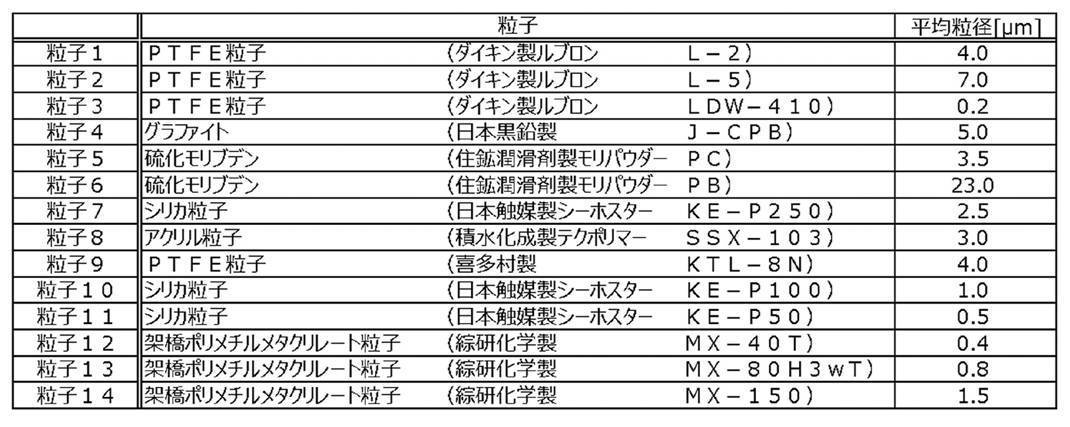
[ドープ組成物の調製に用いた樹脂]
実施例、比較例で保護フィルムの製造のために調製したドープ組成物に添加した樹脂1~8の詳細は、以下の通りである。
実施例、比較例で保護フィルムの製造のために調製したドープ組成物に添加した樹脂1~8の詳細は、以下の通りである。
<樹脂1>
樹脂1として、セルロースアセテート(置換度2.86,重合度350)を用いた。
樹脂1として、セルロースアセテート(置換度2.86,重合度350)を用いた。
<樹脂2>
樹脂2の調製のための脆性改良剤として、最内層が、メタクリル酸メチルに少量のメタクリル酸アリルを用いて重合させた硬質の重合体、中間層が、アクリル酸ブチルを主成分とし、さらにスチレンおよび少量のメタクリル酸アリルを用いて重合させた軟質のゴム弾性体、最外層が、メタクリル酸メチルに少量のアクリル酸エチルを用いて重合させた硬質の重合体からなる3層構造のアクリルゴム弾性体粒子を、公知の方法で合成して得た。得られたアクリルゴム弾性体粒子の平均粒径を、粒子を溶媒分散ゾルとし、日機装社製Nanotrac粒度分析計を用いて、このゾルにおける50%平均粒径として求めたところ、240nmであった。メタクリル酸メチル/アクリル酸メチルの質量比96/4の共重合体のペレット70質量部を脆性改良剤30質量部と混合機により混合した後、2軸押出機で溶融混練し、樹脂2を得た。
樹脂2の調製のための脆性改良剤として、最内層が、メタクリル酸メチルに少量のメタクリル酸アリルを用いて重合させた硬質の重合体、中間層が、アクリル酸ブチルを主成分とし、さらにスチレンおよび少量のメタクリル酸アリルを用いて重合させた軟質のゴム弾性体、最外層が、メタクリル酸メチルに少量のアクリル酸エチルを用いて重合させた硬質の重合体からなる3層構造のアクリルゴム弾性体粒子を、公知の方法で合成して得た。得られたアクリルゴム弾性体粒子の平均粒径を、粒子を溶媒分散ゾルとし、日機装社製Nanotrac粒度分析計を用いて、このゾルにおける50%平均粒径として求めたところ、240nmであった。メタクリル酸メチル/アクリル酸メチルの質量比96/4の共重合体のペレット70質量部を脆性改良剤30質量部と混合機により混合した後、2軸押出機で溶融混練し、樹脂2を得た。
<樹脂3>
特開2012-008248号段落0154に記載の方法により、ラクトン環構造を含有する樹脂3を得た。
特開2012-008248号段落0154に記載の方法により、ラクトン環構造を含有する樹脂3を得た。
<樹脂4>
特開2010-284840号公報の製造例1に記載のイミド化MS(メチルメタクリレート-スチレン)樹脂100質量部およびトリアジン系紫外線吸収剤(アデカ社製T-712)0.62質量部を、2軸混練機にて220℃にて混合して、グルタルイミド構造を有する樹脂4を得た。
特開2010-284840号公報の製造例1に記載のイミド化MS(メチルメタクリレート-スチレン)樹脂100質量部およびトリアジン系紫外線吸収剤(アデカ社製T-712)0.62質量部を、2軸混練機にて220℃にて混合して、グルタルイミド構造を有する樹脂4を得た。
<樹脂5>
特開2009-139720号公報段落0177に記載の方法により、グルタル酸無水物単位を有する樹脂5を得た。
特開2009-139720号公報段落0177に記載の方法により、グルタル酸無水物単位を有する樹脂5を得た。
<樹脂6>
WO2014/156879号段落0148-0155に記載の方法により、ポリエチレンテレフタレート樹脂を含有する樹脂6を得た。
WO2014/156879号段落0148-0155に記載の方法により、ポリエチレンテレフタレート樹脂を含有する樹脂6を得た。
<樹脂7>
樹脂7として、ノルボルネン系樹脂(ZEONOR1420:ガラス転移点Tg=137℃、重量平均分子量30000;日本ゼオン(株)製)のペレットを用いた。
樹脂7として、ノルボルネン系樹脂(ZEONOR1420:ガラス転移点Tg=137℃、重量平均分子量30000;日本ゼオン(株)製)のペレットを用いた。
<樹脂8>
樹脂8として、セルロースアセテート(置換度2.88)を用いた。
樹脂8として、セルロースアセテート(置換度2.88)を用いた。
[保護フィルム1~23、保護フィルム40の作製]
下記に記載の組成物をミキシングタンクに投入し、加熱しながら攪拌して、各成分を溶解し、ドープ組成物を調製した。
(ドープ組成物)
表2-1記載の樹脂 100質量部
ジクロロメタン 534質量部
メタノール 46質量部
表2-1記載の粒子(表1参照) 表2-1記載の質量部
下記に記載の組成物をミキシングタンクに投入し、加熱しながら攪拌して、各成分を溶解し、ドープ組成物を調製した。
(ドープ組成物)
表2-1記載の樹脂 100質量部
ジクロロメタン 534質量部
メタノール 46質量部
表2-1記載の粒子(表1参照) 表2-1記載の質量部
WO2015/064732A1の図1に示されている構成のバンド流延装置を用い、上記ドープ組成物を2000mm幅でステンレス製のエンドレスバンド(流延支持体)に流延ダイから均一に流延した。ドープ組成物中の残留溶媒量が20質量%になった時点で流延支持体からフィルムを剥離した。
剥離されたフィルムを、乾燥ゾーン(雰囲気温度140℃)において30分間乾燥させて、表2-1に記載の保護フィルムを得た。保護フィルムの厚みは、製造条件から求めた値であり、製膜に用いるドープ組成物量により表2-1に記載の膜厚となるように調整した。
この中で保護フィルム17は保護フィルム2と同条件で作製したのち、サンドブラスト法で表面を粗面化した。また保護フィルム18は固体潤滑剤を含む上層と固体潤滑剤を含まない下層の二層積層構造のフィルムを作製した。保護フィルム19は保護フィルム18と同条件で作製したのち、サンドブラスト法で表面を粗面化した。
剥離されたフィルムを、乾燥ゾーン(雰囲気温度140℃)において30分間乾燥させて、表2-1に記載の保護フィルムを得た。保護フィルムの厚みは、製造条件から求めた値であり、製膜に用いるドープ組成物量により表2-1に記載の膜厚となるように調整した。
この中で保護フィルム17は保護フィルム2と同条件で作製したのち、サンドブラスト法で表面を粗面化した。また保護フィルム18は固体潤滑剤を含む上層と固体潤滑剤を含まない下層の二層積層構造のフィルムを作製した。保護フィルム19は保護フィルム18と同条件で作製したのち、サンドブラスト法で表面を粗面化した。
[保護フィルム24、32、34、36、38の作製]
乾燥させた紫外線吸収剤(2,2’-(1,4-フェニレン)ビス(4H-3,1-ベンズオキサジン-4-オン)1質量部、樹脂6(IV=0.63)100質量部を混合し、混練押出機を用い、ペレット化して、粒子と紫外線吸収剤を含有する原料ポリエステル1を得た。また乾燥させた紫外線吸収剤(2,2’-(1,4-フェニレン)ビス(4H-3,1-ベンズオキサジン-4-オン)1質量部、樹脂6(IV=0.63)100質量部、表2-1記載の粒子(表1参照)を混合し、混練押出機を用い、ペレット化して、粒子と紫外線吸収剤を含有する原料ポリエステル2を得た。
乾燥させた紫外線吸収剤(2,2’-(1,4-フェニレン)ビス(4H-3,1-ベンズオキサジン-4-オン)1質量部、樹脂6(IV=0.63)100質量部を混合し、混練押出機を用い、ペレット化して、粒子と紫外線吸収剤を含有する原料ポリエステル1を得た。また乾燥させた紫外線吸収剤(2,2’-(1,4-フェニレン)ビス(4H-3,1-ベンズオキサジン-4-オン)1質量部、樹脂6(IV=0.63)100質量部、表2-1記載の粒子(表1参照)を混合し、混練押出機を用い、ペレット化して、粒子と紫外線吸収剤を含有する原料ポリエステル2を得た。
-フィルム成形工程-
原料ポリエステル1を、含水率20ppm以下に乾燥させた後、直径50mmの1軸混練押出機1のホッパー1に投入し、押出機1で300℃に溶融した(中間層II層)。
また原料ポリエステル2を、含水率20ppm以下に乾燥させた後、直径30mmの1軸混練押出機2のホッパー2に投入し、押出機2で300℃に溶融した(外層I層)。
これらの2種のポリマー溶融物をそれぞれギアポンプ、濾過器(孔径20μm)に介した後、2種2層合流ブロックにて、押出機1から押出されたポリマーがキャストドラム側層(II層)に、押出機2から押出されたポリマーが外層(I層)になるように積層し、幅1200mmのダイよりシート状に押し出した。
溶融樹脂の押出条件は、圧力変動を1%、溶融樹脂の温度分布を2%として、溶融樹脂をダイから押出した。具体的には、背圧を、押出機のバレル内平均圧力に対して1%加圧し、押出機の配管温度を、押出機のバレル内平均温度に対して2%高い温度で加熱した。
ダイから押出した溶融樹脂は、温度25℃に設定された冷却キャストドラム上に押出し、静電印加法を用い冷却キャストドラムに密着させた。冷却キャストドラムに対向配置された剥ぎ取りロールを用いて剥離し、未延伸ポリエステルフィルム1を得た。このとき、I層、II層の厚さの比は12.5:87.5となるように各押出機の吐出量を調整した。
原料ポリエステル1を、含水率20ppm以下に乾燥させた後、直径50mmの1軸混練押出機1のホッパー1に投入し、押出機1で300℃に溶融した(中間層II層)。
また原料ポリエステル2を、含水率20ppm以下に乾燥させた後、直径30mmの1軸混練押出機2のホッパー2に投入し、押出機2で300℃に溶融した(外層I層)。
これらの2種のポリマー溶融物をそれぞれギアポンプ、濾過器(孔径20μm)に介した後、2種2層合流ブロックにて、押出機1から押出されたポリマーがキャストドラム側層(II層)に、押出機2から押出されたポリマーが外層(I層)になるように積層し、幅1200mmのダイよりシート状に押し出した。
溶融樹脂の押出条件は、圧力変動を1%、溶融樹脂の温度分布を2%として、溶融樹脂をダイから押出した。具体的には、背圧を、押出機のバレル内平均圧力に対して1%加圧し、押出機の配管温度を、押出機のバレル内平均温度に対して2%高い温度で加熱した。
ダイから押出した溶融樹脂は、温度25℃に設定された冷却キャストドラム上に押出し、静電印加法を用い冷却キャストドラムに密着させた。冷却キャストドラムに対向配置された剥ぎ取りロールを用いて剥離し、未延伸ポリエステルフィルム1を得た。このとき、I層、II層の厚さの比は12.5:87.5となるように各押出機の吐出量を調整した。
下記の工程で未延伸ポリエステルフィルム1の延伸を行った。
-横延伸工程-
(予熱部)
予熱温度を90℃とし、延伸可能な温度まで加熱した。
(延伸部)
予熱された未延伸ポリエステルフィルム1を、テンター(横延伸機)に導き、フィルムの端部をクリップで把持しながら、下記の方法、条件にてTD方向(フィルム幅方向、横方向)に下記の条件にて横延伸し、5m幅のフィルムを得た。
<<条件>>
・横延伸温度:90℃
・横延伸倍率:4.3倍
(熱固定部)
次いで、ポリエステルフィルムの膜面温度を下記範囲に制御しながら、熱固定処理を行った。
<条件>
・熱固定温度:180℃
・熱固定時間:15秒
(熱緩和部)
熱固定後のポリエステルフィルムを下記の温度に加熱し、フィルムを緩和した。
・熱緩和温度:170℃
・熱緩和率:TD方向(フィルム幅方向、横方向)2%
(冷却部)
次に、熱緩和後のポリエステルフィルムを50℃の冷却温度にて冷却した。
-横延伸工程-
(予熱部)
予熱温度を90℃とし、延伸可能な温度まで加熱した。
(延伸部)
予熱された未延伸ポリエステルフィルム1を、テンター(横延伸機)に導き、フィルムの端部をクリップで把持しながら、下記の方法、条件にてTD方向(フィルム幅方向、横方向)に下記の条件にて横延伸し、5m幅のフィルムを得た。
<<条件>>
・横延伸温度:90℃
・横延伸倍率:4.3倍
(熱固定部)
次いで、ポリエステルフィルムの膜面温度を下記範囲に制御しながら、熱固定処理を行った。
<条件>
・熱固定温度:180℃
・熱固定時間:15秒
(熱緩和部)
熱固定後のポリエステルフィルムを下記の温度に加熱し、フィルムを緩和した。
・熱緩和温度:170℃
・熱緩和率:TD方向(フィルム幅方向、横方向)2%
(冷却部)
次に、熱緩和後のポリエステルフィルムを50℃の冷却温度にて冷却した。
[保護フィルム25、33、35、37、39の作製]
乾燥させた紫外線吸収剤(2,2’-(1,4-フェニレン)ビス(4H-3,1-ベンズオキサジン-4-オン)1質量部、樹脂7(ZEONOR1420)100質量部、粒子2(表1参照)2.7質量部を混合し、混練押出機を用い、ペレット化して、粒子と紫外線吸収剤を含有する原料COP1を得た。また乾燥させた紫外線吸収剤(2,2’-(1,4-フェニレン)ビス(4H-3,1-ベンズオキサジン-4-オン)1質量部、樹脂7(ZEONOR1420)100質量部、表2-1記載の粒子(表1参照)を混合し、混練押出機を用い、ペレット化して、粒子と紫外線吸収剤を含有する原料COP2を得た。
乾燥させた紫外線吸収剤(2,2’-(1,4-フェニレン)ビス(4H-3,1-ベンズオキサジン-4-オン)1質量部、樹脂7(ZEONOR1420)100質量部、粒子2(表1参照)2.7質量部を混合し、混練押出機を用い、ペレット化して、粒子と紫外線吸収剤を含有する原料COP1を得た。また乾燥させた紫外線吸収剤(2,2’-(1,4-フェニレン)ビス(4H-3,1-ベンズオキサジン-4-オン)1質量部、樹脂7(ZEONOR1420)100質量部、表2-1記載の粒子(表1参照)を混合し、混練押出機を用い、ペレット化して、粒子と紫外線吸収剤を含有する原料COP2を得た。
-フィルム成形工程-
原料COP1を、含水率20ppm以下に乾燥させた後、直径50mmの1軸混練押出機1のホッパー1に投入し、押出機1で240℃に溶融した(中間層II層)。
また原料COP2を、含水率20ppm以下に乾燥させた後、直径30mmの1軸混練押出機2のホッパー2に投入し、押出機2で240℃に溶融した(外層I層)。
これらの2種のポリマー溶融物をそれぞれギアポンプ、濾過器(孔径20μm)に介した後、2種2層合流ブロックにて、押出機1から押出されたポリマーがキャストドラム側層(II層)に、押出機2から押出されたポリマーが外層(I層)になるように積層し、幅1200mmのダイよりシート状に押し出した。
溶融樹脂の押出条件は、圧力変動を1%、溶融樹脂の温度分布を2%として、溶融樹脂をダイから押出した。具体的には、背圧を、押出機のバレル内平均圧力に対して1%加圧し、押出機の配管温度を、押出機のバレル内平均温度に対して2%高い温度で加熱した。
ダイから押出した溶融樹脂は、温度25℃に設定された冷却キャストドラム上に押出し、静電印加法を用い冷却キャストドラムに密着させた。冷却キャストドラムに対向配置された剥ぎ取りロールを用いて剥離し、未延伸COP1を得た。このとき、I層、II層の厚さの比は12.5:87.5となるように各押出機の吐出量を調整した。
原料COP1を、含水率20ppm以下に乾燥させた後、直径50mmの1軸混練押出機1のホッパー1に投入し、押出機1で240℃に溶融した(中間層II層)。
また原料COP2を、含水率20ppm以下に乾燥させた後、直径30mmの1軸混練押出機2のホッパー2に投入し、押出機2で240℃に溶融した(外層I層)。
これらの2種のポリマー溶融物をそれぞれギアポンプ、濾過器(孔径20μm)に介した後、2種2層合流ブロックにて、押出機1から押出されたポリマーがキャストドラム側層(II層)に、押出機2から押出されたポリマーが外層(I層)になるように積層し、幅1200mmのダイよりシート状に押し出した。
溶融樹脂の押出条件は、圧力変動を1%、溶融樹脂の温度分布を2%として、溶融樹脂をダイから押出した。具体的には、背圧を、押出機のバレル内平均圧力に対して1%加圧し、押出機の配管温度を、押出機のバレル内平均温度に対して2%高い温度で加熱した。
ダイから押出した溶融樹脂は、温度25℃に設定された冷却キャストドラム上に押出し、静電印加法を用い冷却キャストドラムに密着させた。冷却キャストドラムに対向配置された剥ぎ取りロールを用いて剥離し、未延伸COP1を得た。このとき、I層、II層の厚さの比は12.5:87.5となるように各押出機の吐出量を調整した。
下記の工程で未延伸COP1の延伸を行った。
-横延伸工程-
(予熱部)
予熱温度を137℃とし、延伸可能な温度まで加熱した。
(延伸部)
予熱された未延伸COP1を、テンター(横延伸機)に導き、フィルムの端部をクリップで把持しながら、下記の方法、条件にてTD方向(フィルム幅方向、横方向)に下記の条件にて横延伸し、1.4m幅のフィルムを得た。
<<条件>>
・横延伸温度:137℃
・横延伸倍率:1.2倍
-横延伸工程-
(予熱部)
予熱温度を137℃とし、延伸可能な温度まで加熱した。
(延伸部)
予熱された未延伸COP1を、テンター(横延伸機)に導き、フィルムの端部をクリップで把持しながら、下記の方法、条件にてTD方向(フィルム幅方向、横方向)に下記の条件にて横延伸し、1.4m幅のフィルムを得た。
<<条件>>
・横延伸温度:137℃
・横延伸倍率:1.2倍
[保護フィルム26~31、保護フィルム41の作製]
下記に記載の組成物をミキシングタンクに投入し、加熱しながら攪拌して、各成分を溶解し、ドープ組成物を調製した。
(ドープ組成物)
表2-1記載の樹脂 100質量部
ジクロロメタン 534質量部
メタノール 46質量部
表2-1記載の粒子(表1参照) 表2-1記載の質量部
表2-1記載の添加剤 各添加剤の組成は表3に記載
下記に記載の組成物をミキシングタンクに投入し、加熱しながら攪拌して、各成分を溶解し、ドープ組成物を調製した。
(ドープ組成物)
表2-1記載の樹脂 100質量部
ジクロロメタン 534質量部
メタノール 46質量部
表2-1記載の粒子(表1参照) 表2-1記載の質量部
表2-1記載の添加剤 各添加剤の組成は表3に記載
これらのドープ組成物を用い、先の<0115>段落記載の方法で保護フィルム26~31、保護フィルム41を作製した。
<0124>
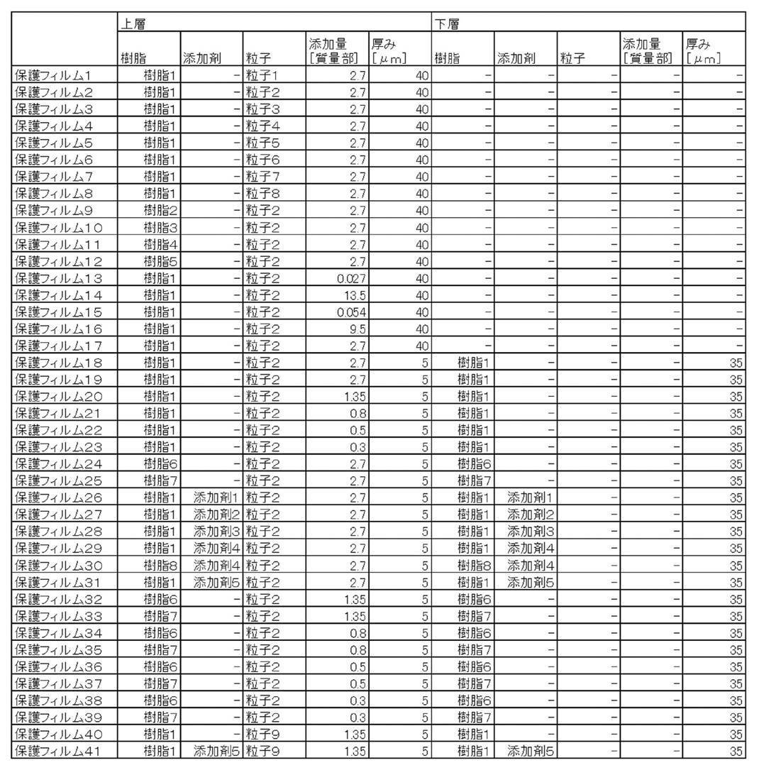
<0124>


ここで表3中の各添加剤は下記の材料を用いた。
TPP:トリフェニルホスフェート
BDP:ビフェニルジフェニルフォスフェート
糖エステル1:第一工業化学社製モノペットSB(登録商標)
糖エステル2:イーストマン・ケミカル社製SAIB-100
化合物A:下記組成のエステルオリゴマー

化合物B:以下の構造の化合物

化合物C:以下の構造の化合物
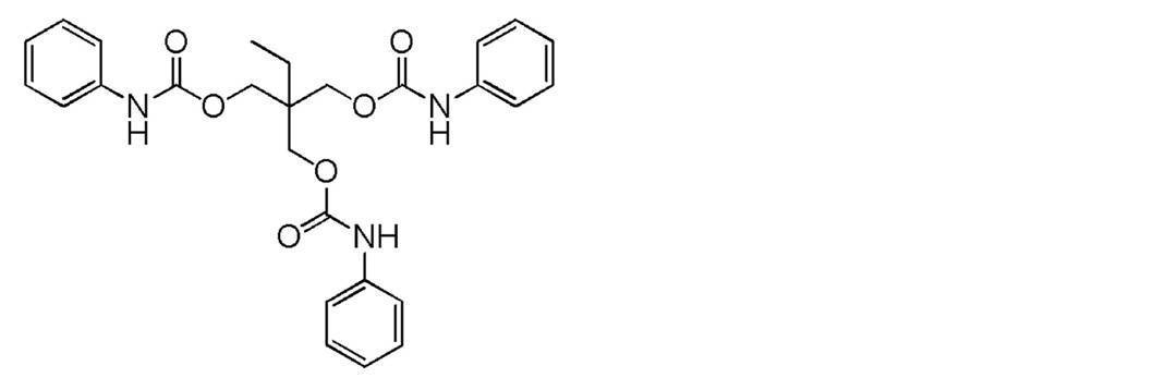
UV1:以下の構造の化合物
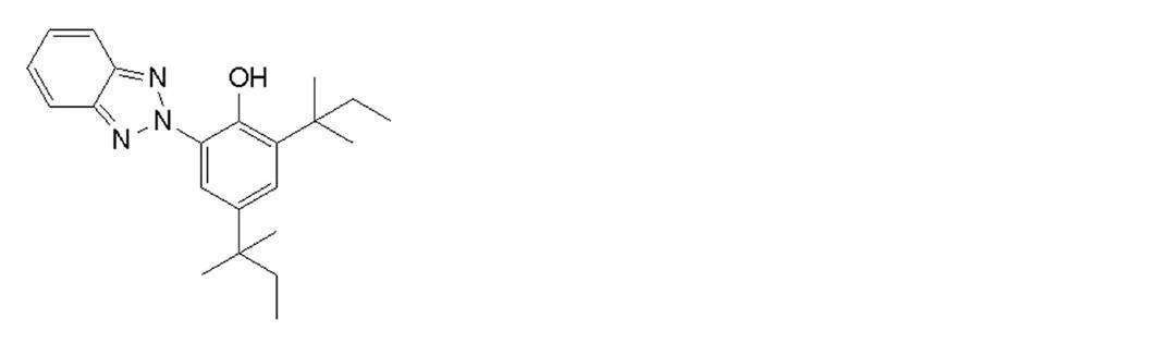
UV2:以下の構造の化合物
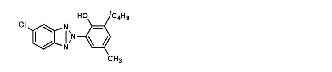
TPP:トリフェニルホスフェート
BDP:ビフェニルジフェニルフォスフェート
糖エステル1:第一工業化学社製モノペットSB(登録商標)
糖エステル2:イーストマン・ケミカル社製SAIB-100
化合物A:下記組成のエステルオリゴマー
化合物B:以下の構造の化合物
化合物C:以下の構造の化合物
UV1:以下の構造の化合物
UV2:以下の構造の化合物
[保護フィルム42~56の作製]
下記に記載の組成物をミキシングタンクに投入し、加熱しながら攪拌して、各成分を溶解し、ドープ組成物を調製した。その組成を表2-2に示す。保護フィルム42-56の作製においては、表2-2に記載したようにそれぞれ2種類の粒子を使用した。
(ドープ組成物)
表2-2記載の樹脂 100質量部
ジクロロメタン 534質量部
メタノール 46質量部
表2-2記載の粒子(表1参照) 表2-2記載の質量部
表2-2記載の添加剤(各添加剤の組成は表3に記載) 表2-2記載の質量部
下記に記載の組成物をミキシングタンクに投入し、加熱しながら攪拌して、各成分を溶解し、ドープ組成物を調製した。その組成を表2-2に示す。保護フィルム42-56の作製においては、表2-2に記載したようにそれぞれ2種類の粒子を使用した。
(ドープ組成物)
表2-2記載の樹脂 100質量部
ジクロロメタン 534質量部
メタノール 46質量部
表2-2記載の粒子(表1参照) 表2-2記載の質量部
表2-2記載の添加剤(各添加剤の組成は表3に記載) 表2-2記載の質量部
これらのドープ組成物を用い、先の<0115>段落記載の方法で保護フィルム42~56を作製した。
各実施例、比較例について、上記方法により、各種評価用の保護フィルムおよび偏光板を製造して液晶表示装置に用いるための保護フィルムを作製した。
[実施例、比較例の偏光板]
<偏光子の作製>
特開2001-141926号公報の実施例1に従い、延伸したポリビニルアルコール系フィルムにヨウ素を吸着させて、厚み7μmの偏光子(ヨウ素染色ポリビニルアルコール系フィルム)を作製した。
<偏光子の作製>
特開2001-141926号公報の実施例1に従い、延伸したポリビニルアルコール系フィルムにヨウ素を吸着させて、厚み7μmの偏光子(ヨウ素染色ポリビニルアルコール系フィルム)を作製した。
<偏光板の作製(偏光子と保護フィルムとの貼り合わせ)>
上記で作製した偏光子を、一方の保護フィルムとして各実施例、比較例の保護フィルムを用いて、このフィルムの一方の表面を貼り合わせ面として接着剤を介して貼り合わせた。他方の保護フィルムとしては、市販のセルロースアシレートフィルム(富士フイルム社製フジタック(登録商標)ZRD40) に鹸化処理を施し、鹸化処理を施した面を貼り合わせ面として接着剤を介して貼り合わせた。鹸化処理は、以下のように実施した。上記セルロースアシレートフィルムを、液温を55℃に保った1.5mol/LのNaOH水溶液(鹸化液)に2分間浸漬した後、フィルムを水洗し、その後、液温25℃の0.05mol/Lの硫酸水溶液に30秒浸漬した後、更に30秒流水下に通して、フィルムを中性の状態にした。そして、エアナイフによる水切りを3回繰り返し、水を落とした後にフィルムを雰囲気温度70℃の乾燥ゾーンに15秒間滞留させて乾燥し、鹸化処理したフィルムを得た。
上記で作製した偏光子を、一方の保護フィルムとして各実施例、比較例の保護フィルムを用いて、このフィルムの一方の表面を貼り合わせ面として接着剤を介して貼り合わせた。他方の保護フィルムとしては、市販のセルロースアシレートフィルム(富士フイルム社製フジタック(登録商標)ZRD40) に鹸化処理を施し、鹸化処理を施した面を貼り合わせ面として接着剤を介して貼り合わせた。鹸化処理は、以下のように実施した。上記セルロースアシレートフィルムを、液温を55℃に保った1.5mol/LのNaOH水溶液(鹸化液)に2分間浸漬した後、フィルムを水洗し、その後、液温25℃の0.05mol/Lの硫酸水溶液に30秒浸漬した後、更に30秒流水下に通して、フィルムを中性の状態にした。そして、エアナイフによる水切りを3回繰り返し、水を落とした後にフィルムを雰囲気温度70℃の乾燥ゾーンに15秒間滞留させて乾燥し、鹸化処理したフィルムを得た。
各実施例、比較例について、上記方法により、各種評価用の偏光板および液晶表示装置製造用の偏光板を作製した。
[実施例、比較例の液晶表示装置]
市販の液晶テレビ(IPSモードのスリム型42型液晶テレビ)から、液晶セルを挟んでいる2枚の偏光板のうちバックライト側偏光板(リア偏光板)を剥がし取り、各実施例、比較例の偏光板を、保護フィルムがバックライト側に配置されるように、接着剤を介して液晶セルに再貼合した。このときの液晶テレビの構成は、光源側から表順に、(1)光源を側面に配置した導光板/(2)拡散板/(3)集光シート(プリズムシート)/(4)拡散シート/(5)上記で作製した偏光板(保護フィルムがバックライト側に配置されるように貼合したリア偏光板/(6)液晶セル/(7)フロント偏光板、となった。したがって、リア偏光板のアウター側保護フィルムが、上記で作製した保護フィルムである。上記で作製した各種部材以外は、上記市販の液晶テレビに組み込まれていた部材である。
こうして、実施例、比較例の液晶表示装置を作製した。
<0135>
[保護フィルムの評価方法]
<算術平均粗さRa>
各実施例、比較例で用いた保護フィルムの液晶表示装置において最もバックライトユニット側に位置する面となる表面において、算術平均粗さRaを測定した。測定されたRaを表5-1、5-2に示す。Raの測定は、先に記載した方法により、AFMとして走査型プローブ顕微鏡(エスアイアイ・ナノテクノロジー社製SPA400)をAFMモードで用いて行った。
<保護フィルム内の固体潤滑剤の粒径>
各実施例、比較例で作製した保護フィルム内の固体潤滑剤の粒径は先に記載した方法により測定した。測定された粒径を表5-1、表5-2に示す。
<全ヘイズ>
各実施例、比較例で作製した保護フィルムの全ヘイズを先に記載した方法により測定した。測定された全ヘイズを表5-1、表5-2に示す。
<内部ヘイズ>
各実施例、比較例で作製した保護フィルムの内部ヘイズを先に記載した方法により測定した。測定された内部ヘイズを表5-1、表5-2に示す。
市販の液晶テレビ(IPSモードのスリム型42型液晶テレビ)から、液晶セルを挟んでいる2枚の偏光板のうちバックライト側偏光板(リア偏光板)を剥がし取り、各実施例、比較例の偏光板を、保護フィルムがバックライト側に配置されるように、接着剤を介して液晶セルに再貼合した。このときの液晶テレビの構成は、光源側から表順に、(1)光源を側面に配置した導光板/(2)拡散板/(3)集光シート(プリズムシート)/(4)拡散シート/(5)上記で作製した偏光板(保護フィルムがバックライト側に配置されるように貼合したリア偏光板/(6)液晶セル/(7)フロント偏光板、となった。したがって、リア偏光板のアウター側保護フィルムが、上記で作製した保護フィルムである。上記で作製した各種部材以外は、上記市販の液晶テレビに組み込まれていた部材である。
こうして、実施例、比較例の液晶表示装置を作製した。
<0135>
[保護フィルムの評価方法]
<算術平均粗さRa>
各実施例、比較例で用いた保護フィルムの液晶表示装置において最もバックライトユニット側に位置する面となる表面において、算術平均粗さRaを測定した。測定されたRaを表5-1、5-2に示す。Raの測定は、先に記載した方法により、AFMとして走査型プローブ顕微鏡(エスアイアイ・ナノテクノロジー社製SPA400)をAFMモードで用いて行った。
<保護フィルム内の固体潤滑剤の粒径>
各実施例、比較例で作製した保護フィルム内の固体潤滑剤の粒径は先に記載した方法により測定した。測定された粒径を表5-1、表5-2に示す。
<全ヘイズ>
各実施例、比較例で作製した保護フィルムの全ヘイズを先に記載した方法により測定した。測定された全ヘイズを表5-1、表5-2に示す。
<内部ヘイズ>
各実施例、比較例で作製した保護フィルムの内部ヘイズを先に記載した方法により測定した。測定された内部ヘイズを表5-1、表5-2に示す。
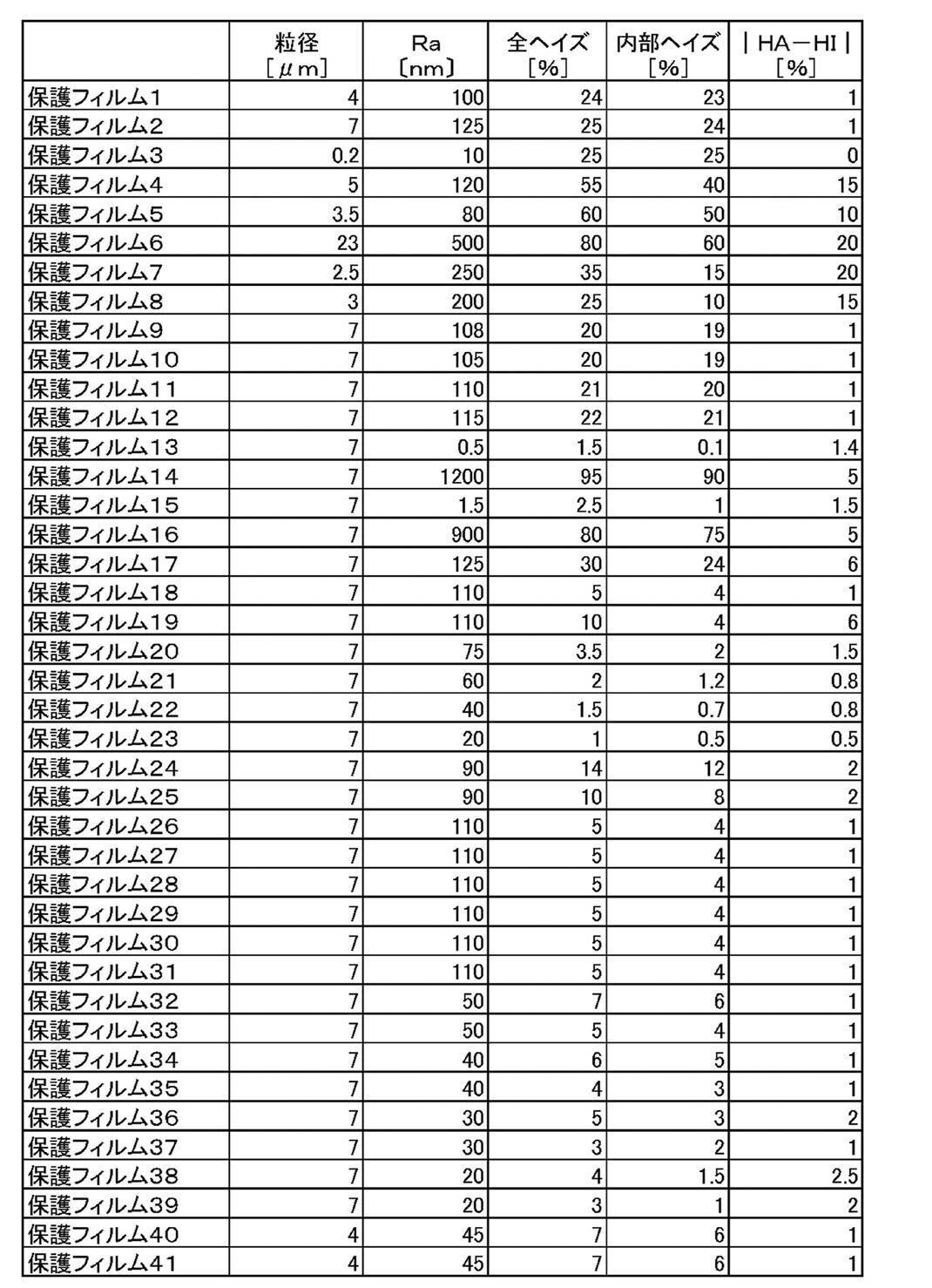
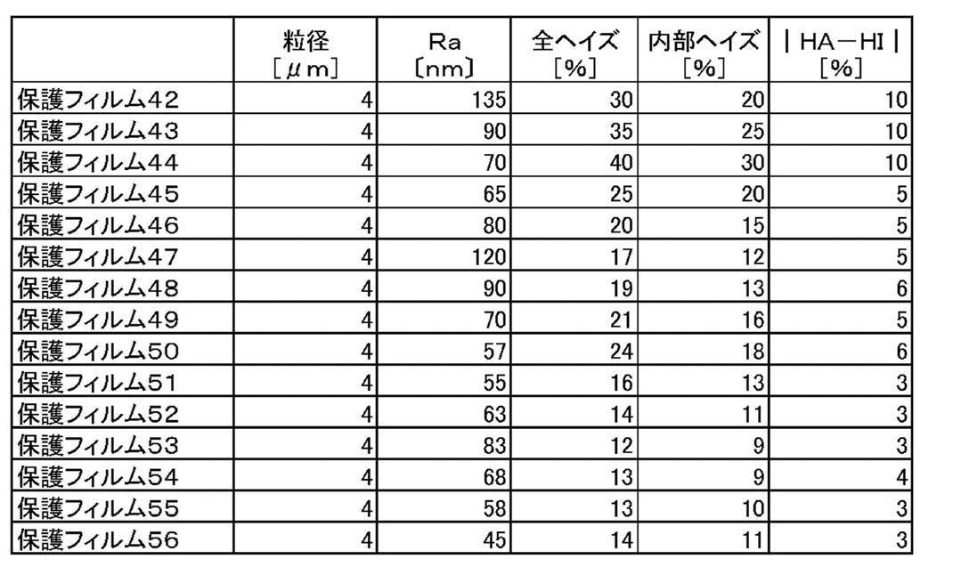
[液晶表示装置の評価方法]
<表示性能の評価1(光漏れの評価)>
各実施例、比較例の液晶表示装置を振動を加えた後に点灯試験を行い、表示面で光漏れが確認されるか否かを目視で評価した。具体的には、試験機として梱包包装試験機(アイメックス社製BF-50UT)を使用し、重力加速度1.5G(1.0Gは、9.80665m/s2)、振幅0.8mm、周波数10~40Hzで周期的に変化する振動をx方向、y方向、z方向に20分間加えた。振動を加えた後に点灯試験を行った。
以上の評価を、各実施例、比較例について実施し、光漏れの有無を確認した。確認後に新しい偏光板に変更し、合計30回同様の評価を行った。下記基準により表示性能を評価した。AAA~Cは実用上好ましい。
AAA:光漏れが視認されず、偏光板を取り出して観察しても傷がない。
AA:光漏れが視認されず、偏光板を取り出して観察した時にかすかに傷がある。
A:光漏れが視認されず、偏光板を取り出して観察した時にはっきり見える傷がある。
B:1回、光漏れが視認される。
C:2回、光漏れが視認される。
D:3回以上、光漏れが視認される。
<表示性能の評価1(光漏れの評価)>
各実施例、比較例の液晶表示装置を振動を加えた後に点灯試験を行い、表示面で光漏れが確認されるか否かを目視で評価した。具体的には、試験機として梱包包装試験機(アイメックス社製BF-50UT)を使用し、重力加速度1.5G(1.0Gは、9.80665m/s2)、振幅0.8mm、周波数10~40Hzで周期的に変化する振動をx方向、y方向、z方向に20分間加えた。振動を加えた後に点灯試験を行った。
以上の評価を、各実施例、比較例について実施し、光漏れの有無を確認した。確認後に新しい偏光板に変更し、合計30回同様の評価を行った。下記基準により表示性能を評価した。AAA~Cは実用上好ましい。
AAA:光漏れが視認されず、偏光板を取り出して観察しても傷がない。
AA:光漏れが視認されず、偏光板を取り出して観察した時にかすかに傷がある。
A:光漏れが視認されず、偏光板を取り出して観察した時にはっきり見える傷がある。
B:1回、光漏れが視認される。
C:2回、光漏れが視認される。
D:3回以上、光漏れが視認される。
<表示性能の評価2(輝度の評価)>
各実施例、比較例の液晶表示装置について点灯試験を行い、表示面の正面から輝度の評価を行い、下記基準により輝度を評価した。AAA~Cは実用上好ましい。
AAA:輝度310cd/m2以上
AA:輝度305cd/m2以上310cd/m2未満
A:輝度300cd/m2以上305cd/m2未満
B:輝度290cd/m2以上300cd/m2未満
C:輝度280cd/m2以上290cd/m2未満
D:輝度280cd/m2未満
各実施例、比較例の液晶表示装置について点灯試験を行い、表示面の正面から輝度の評価を行い、下記基準により輝度を評価した。AAA~Cは実用上好ましい。
AAA:輝度310cd/m2以上
AA:輝度305cd/m2以上310cd/m2未満
A:輝度300cd/m2以上305cd/m2未満
B:輝度290cd/m2以上300cd/m2未満
C:輝度280cd/m2以上290cd/m2未満
D:輝度280cd/m2未満
以上の評価結果を、表6-1、表6-2に示す。表6-1、表6-2に示す結果から、実施例の液晶表示装置は、比較例の液晶表示装置と比べて、光漏れ防止の向上が達成されていることが確認できる。固体潤滑剤としてはPTFEがより好適である。特に粒子9のPTFE粒子は完全な焼成品であり、表示性能改善の点でより好適である。また実施例41~49の結果から、固体潤滑剤とフィラーを併用することで光漏れ防止の効果が向上することが確認できる。
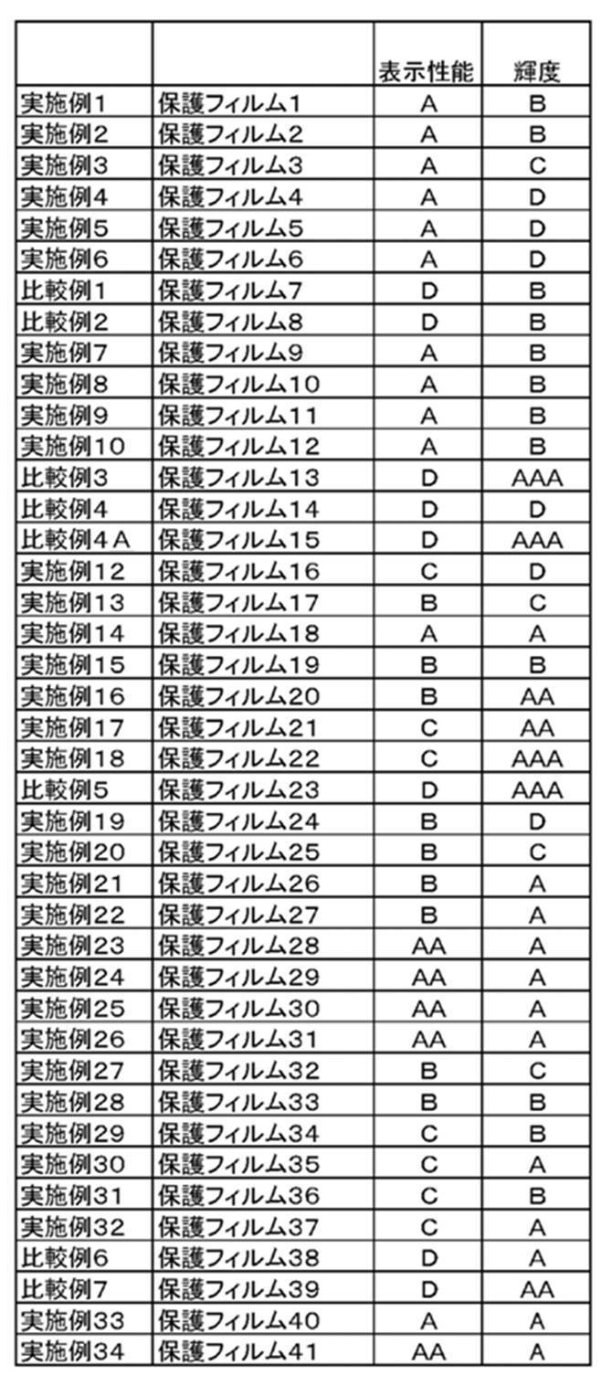

本発明は、液晶表示装置の技術分野において有用である。
Claims (14)
- 少なくとも液晶セルおよび偏光板を含む液晶パネルと、少なくとも光源を含むバックライトユニットとをこの順で配置した液晶表示装置であって、
前記偏光板が少なくとも一枚の保護フィルムおよび偏光子を具備しており、
前記保護フィルムは樹脂を用いて構成されており、
前記保護フィルムは固体潤滑剤を含み、
前記固体潤滑剤の含有量は前記樹脂100質量部に対して0.5~10質量部であり、
前記バックライトユニットと最隣接した前記保護フィルムの表面の算術平均粗さRaが1~1000nmであることを特徴とする液晶表示装置。 - 前記固体潤滑剤がポリテトラフルオロエチレンをを含む請求項1に記載の液晶表示装置。
- 前記固体潤滑剤の平均粒径が0.01μm~30μmの範囲である請求項1または2に記載の液晶表示装置。
- 前記バックライトユニットと最隣接した前記保護フィルムの表面の算術平均粗さRaが25nm~300nmの範囲である請求項1~3のいずれか1項に記載の液晶表示装置。
- 前記バックライトユニットと最隣接した前記保護フィルムの全ヘイズHAと内部ヘイズHIの差の絶対値|HA-HI|が0%~5%の範囲である請求項4に記載の液晶表示装置。
- 固体潤滑剤を含み、かつ、一方の表面Aおよび他方の表面Bのうち前記表面Aの算術平均粗さRaが1nm~1000nmの範囲であることを特徴とする保護フィルム。
- 前記固体潤滑剤がポリテトラフルオロエチレンを主成分とする材料である請求項6に記載の保護フィルム。
- 前記固体潤滑剤の平均粒径が0.01μm~30μmの範囲である請求項6または7に記載の保護フィルム。
- 前記表面Aの算術平均粗さRaが25nm~300nmの範囲である請求項6~8のいずれか1項に記載の保護フィルム。
- 全ヘイズHAと内部ヘイズHIの差の絶対値|HA-HI|が0%~5%の範囲である請求項9に記載の保護フィルム。
- 請求項6~10のいずれか1項に記載の保護フィルムと偏光子とを含む偏光板。
- 前記保護フィルムをアウター側保護フィルムとして含む請求項11に記載の偏光板。
- 前記保護フィルムは、前記表面Bが、前記偏光子に最隣接している請求項11または12に記載の偏光板。
- 請求項11~13のいずれか1項に記載の偏光板と液晶表示素子とを含む液晶パネル。
Priority Applications (1)
| Application Number | Priority Date | Filing Date | Title |
|---|---|---|---|
| JP2017564169A JP6754379B2 (ja) | 2016-01-26 | 2017-01-16 | 液晶表示装置、保護フィルム、偏光板および液晶パネル |
Applications Claiming Priority (6)
| Application Number | Priority Date | Filing Date | Title |
|---|---|---|---|
| JP2016012739 | 2016-01-26 | ||
| JP2016-012739 | 2016-01-26 | ||
| JP2016061185 | 2016-03-25 | ||
| JP2016-061185 | 2016-03-25 | ||
| JP2016-082727 | 2016-04-18 | ||
| JP2016082727 | 2016-04-18 |
Publications (1)
| Publication Number | Publication Date |
|---|---|
| WO2017130757A1 true WO2017130757A1 (ja) | 2017-08-03 |
Family
ID=59399106
Family Applications (1)
| Application Number | Title | Priority Date | Filing Date |
|---|---|---|---|
| PCT/JP2017/001152 Ceased WO2017130757A1 (ja) | 2016-01-26 | 2017-01-16 | 液晶表示装置、保護フィルム、偏光板および液晶パネル |
Country Status (2)
| Country | Link |
|---|---|
| JP (1) | JP6754379B2 (ja) |
| WO (1) | WO2017130757A1 (ja) |
Citations (4)
| Publication number | Priority date | Publication date | Assignee | Title |
|---|---|---|---|---|
| JP2007099824A (ja) * | 2005-09-30 | 2007-04-19 | Fujifilm Corp | 環状オレフィン系樹脂フィルム、偏光板および液晶表示装置 |
| JP2008282001A (ja) * | 2007-04-10 | 2008-11-20 | Fujifilm Corp | マトリクス型液晶表示装置 |
| JP2010164931A (ja) * | 2008-12-15 | 2010-07-29 | Fujifilm Corp | 液晶表示装置および液晶表示装置の製造方法 |
| JP2012037881A (ja) * | 2010-07-16 | 2012-02-23 | Dainippon Printing Co Ltd | 保護フィルム、下偏光板、液晶表示パネルおよび表示装置 |
Family Cites Families (1)
| Publication number | Priority date | Publication date | Assignee | Title |
|---|---|---|---|---|
| JP2001341426A (ja) * | 2000-06-01 | 2001-12-11 | Toppan Printing Co Ltd | 偽造防止を施した可逆性記録シート及び可逆性記録媒体 |
-
2017
- 2017-01-16 JP JP2017564169A patent/JP6754379B2/ja active Active
- 2017-01-16 WO PCT/JP2017/001152 patent/WO2017130757A1/ja not_active Ceased
Patent Citations (4)
| Publication number | Priority date | Publication date | Assignee | Title |
|---|---|---|---|---|
| JP2007099824A (ja) * | 2005-09-30 | 2007-04-19 | Fujifilm Corp | 環状オレフィン系樹脂フィルム、偏光板および液晶表示装置 |
| JP2008282001A (ja) * | 2007-04-10 | 2008-11-20 | Fujifilm Corp | マトリクス型液晶表示装置 |
| JP2010164931A (ja) * | 2008-12-15 | 2010-07-29 | Fujifilm Corp | 液晶表示装置および液晶表示装置の製造方法 |
| JP2012037881A (ja) * | 2010-07-16 | 2012-02-23 | Dainippon Printing Co Ltd | 保護フィルム、下偏光板、液晶表示パネルおよび表示装置 |
Also Published As
| Publication number | Publication date |
|---|---|
| JPWO2017130757A1 (ja) | 2018-09-27 |
| JP6754379B2 (ja) | 2020-09-09 |
Similar Documents
| Publication | Publication Date | Title |
|---|---|---|
| KR101216785B1 (ko) | 편광판, 및 그것을 이용한 액정 표시 장치 | |
| KR101242294B1 (ko) | 셀룰로오스에스테르 필름, 편광판 및 표시 장치 | |
| KR102226092B1 (ko) | 편광판 및 액정 표시 장치 | |
| JPWO2007069474A1 (ja) | 偏光板の製造方法、偏光板及び液晶表示装置 | |
| KR20080039933A (ko) | 액정 표시 장치 | |
| JP2006048007A (ja) | 光学用セルロースアシレートフィルム、偏光板及び液晶表示装置 | |
| WO2007066470A1 (ja) | 偏光板、偏光板の製造方法及び液晶表示装置 | |
| US20150346390A1 (en) | Optical film, polarizing plate and liquid crystal display device | |
| US20120076955A1 (en) | Optical film and its production method, polarizer and liquid crystal display device | |
| KR20060051547A (ko) | 편광판 및 액정 표시 장치 | |
| WO2014057950A1 (ja) | 光学フィルム、光学フィルムの製造方法、偏光板、及び画像表示装置 | |
| JP6330808B2 (ja) | 偏光板および液晶表示装置 | |
| KR20060048050A (ko) | 광학 보상 시트, 편광판, 및 액정 표시 장치 | |
| US8974875B2 (en) | Cellulose acylate film, polarizing plate using the same and liquid crystal display device | |
| JP2014081598A (ja) | 光学フィルム及びその製造方法ならびに偏光板 | |
| JP6556598B2 (ja) | 液晶表示装置 | |
| JP5861502B2 (ja) | 液晶表示装置 | |
| CN102262317B (zh) | Ips或ffs模式液晶显示装置 | |
| US20120207976A1 (en) | Polarizing plate and liquid crystal display employing the same | |
| JP6754379B2 (ja) | 液晶表示装置、保護フィルム、偏光板および液晶パネル | |
| JP2008307730A (ja) | 光学用フィルムの製造方法、光学用フィルム、偏光板及び液晶表示装置 | |
| CN100492070C (zh) | 纤维素酰化物薄膜、偏振片和液晶显示器 | |
| JP2007326244A (ja) | セルロースアシレートフィルムの製造方法、セルロースアシレートフィルム、位相差フィルム、偏光板及び液晶表示装置 | |
| WO2014148559A1 (ja) | 光学フィルム、それを用いた偏光板および液晶表示装置 | |
| JP2007178992A (ja) | 偏光板及び液晶表示装置 |
Legal Events
| Date | Code | Title | Description |
|---|---|---|---|
| 121 | Ep: the epo has been informed by wipo that ep was designated in this application |
Ref document number: 17743988 Country of ref document: EP Kind code of ref document: A1 |
|
| ENP | Entry into the national phase |
Ref document number: 2017564169 Country of ref document: JP Kind code of ref document: A |
|
| NENP | Non-entry into the national phase |
Ref country code: DE |
|
| 122 | Ep: pct application non-entry in european phase |
Ref document number: 17743988 Country of ref document: EP Kind code of ref document: A1 |