WO2017126246A1 - 通信システム、端末及び通信制御方法 - Google Patents
通信システム、端末及び通信制御方法 Download PDFInfo
- Publication number
- WO2017126246A1 WO2017126246A1 PCT/JP2016/086557 JP2016086557W WO2017126246A1 WO 2017126246 A1 WO2017126246 A1 WO 2017126246A1 JP 2016086557 W JP2016086557 W JP 2016086557W WO 2017126246 A1 WO2017126246 A1 WO 2017126246A1
- Authority
- WO
- WIPO (PCT)
- Prior art keywords
- terminal
- wireless connection
- connection destination
- service
- data
- Prior art date
- Legal status (The legal status is an assumption and is not a legal conclusion. Google has not performed a legal analysis and makes no representation as to the accuracy of the status listed.)
- Ceased
Links
Images





Classifications
-
- H—ELECTRICITY
- H04—ELECTRIC COMMUNICATION TECHNIQUE
- H04L—TRANSMISSION OF DIGITAL INFORMATION, e.g. TELEGRAPHIC COMMUNICATION
- H04L61/00—Network arrangements, protocols or services for addressing or naming
- H04L61/50—Address allocation
- H04L61/5007—Internet protocol [IP] addresses
-
- H—ELECTRICITY
- H04—ELECTRIC COMMUNICATION TECHNIQUE
- H04L—TRANSMISSION OF DIGITAL INFORMATION, e.g. TELEGRAPHIC COMMUNICATION
- H04L65/00—Network arrangements, protocols or services for supporting real-time applications in data packet communication
- H04L65/1066—Session management
- H04L65/1069—Session establishment or de-establishment
-
- H—ELECTRICITY
- H04—ELECTRIC COMMUNICATION TECHNIQUE
- H04L—TRANSMISSION OF DIGITAL INFORMATION, e.g. TELEGRAPHIC COMMUNICATION
- H04L65/00—Network arrangements, protocols or services for supporting real-time applications in data packet communication
- H04L65/1066—Session management
- H04L65/1073—Registration or de-registration
-
- H—ELECTRICITY
- H04—ELECTRIC COMMUNICATION TECHNIQUE
- H04L—TRANSMISSION OF DIGITAL INFORMATION, e.g. TELEGRAPHIC COMMUNICATION
- H04L65/00—Network arrangements, protocols or services for supporting real-time applications in data packet communication
- H04L65/1066—Session management
- H04L65/1101—Session protocols
- H04L65/1104—Session initiation protocol [SIP]
-
- H—ELECTRICITY
- H04—ELECTRIC COMMUNICATION TECHNIQUE
- H04W—WIRELESS COMMUNICATION NETWORKS
- H04W36/00—Hand-off or reselection arrangements
- H04W36/02—Buffering or recovering information during reselection ; Modification of the traffic flow during hand-off
- H04W36/023—Buffering or recovering information during reselection
-
- H—ELECTRICITY
- H04—ELECTRIC COMMUNICATION TECHNIQUE
- H04W—WIRELESS COMMUNICATION NETWORKS
- H04W88/00—Devices specially adapted for wireless communication networks, e.g. terminals, base stations or access point devices
- H04W88/02—Terminal devices
- H04W88/04—Terminal devices adapted for relaying to or from another terminal or user
-
- H—ELECTRICITY
- H04—ELECTRIC COMMUNICATION TECHNIQUE
- H04W—WIRELESS COMMUNICATION NETWORKS
- H04W36/00—Hand-off or reselection arrangements
- H04W36/03—Reselecting a link using a direct mode connection
-
- H—ELECTRICITY
- H04—ELECTRIC COMMUNICATION TECHNIQUE
- H04W—WIRELESS COMMUNICATION NETWORKS
- H04W4/00—Services specially adapted for wireless communication networks; Facilities therefor
- H04W4/06—Selective distribution of broadcast services, e.g. multimedia broadcast multicast service [MBMS]; Services to user groups; One-way selective calling services
- H04W4/10—Push-to-Talk [PTT] or Push-On-Call services
Definitions
- the present disclosure relates to a communication system, a terminal, and a communication control method.
- MCPTT Mobility Critical Push To Talk
- 3GPP 3rd Generation Partnership Project
- Non-Patent Document 1 describes requirements for formulating details of MCPTT services and systems. According to Non-Patent Document 1, as an MCPTT service, an on-network service, an off-network service, or a service using both the on-network service and the off-network service is considered.
- the on-network service is a service using GCSE_LTE (Group Communication System Enablers LTE for example: see Non-Patent Document 2 and Non-Patent Document 3).
- GCSE_LTE Group Communication System Enablers LTE for example: see Non-Patent Document 2 and Non-Patent Document 3
- UE User ⁇ Equipment
- Non-Patent Document 10 or Non-Patent Document 11 Unicast communication using an EPS (Evolved Packet System) bearer described in (2) may be performed, or MBMS communication using an MBMS (Multimedia Broadcast and Multicast Service) bearer described in Non-Patent Document 12 may be performed.
- EPS Evolved Packet System
- MBMS Multimedia Broadcast and Multicast Service
- the off-network service is a service using ProSe (Proximity Service: for example, see Non-Patent Document 4, Non-Patent Document 5, Non-Patent Document 6, and Non-Patent Document 7) that is direct communication between terminals. Prose communication is sometimes called sidelink communication.
- the UE-to-Network relay (relay) described in Non-Patent Document 1, Non-Patent Document 6, Non-Patent Document 9, etc. is used as a service using both the On-network service and the off-network service. There is service that we did.
- a service using UE-to-Network relay is a UE that exists in the coverage of the base station (eNB: eNode B), a UE (remote UE) that is outside the eNB coverage and EPS It is a service that functions as a relay UE that relays communication with the.
- an off-network service using ProSe communication is performed between the relay UE and the remote UE, and GCSE_LTE is set between the relay UE and the EPC (EPC: Evolved Packet Core, hereinafter also referred to as Packet Core).
- EPC Evolved Packet Core
- the on-network service used is performed.
- This relay UE functions as a Layer 3 relay, that is, a Layer 3 router for a remote UE.
- the UE of the user who receives the provision of the MCPTT service belongs to the group of the MCPTT service. There may be a plurality of groups to which the UE belongs at the same time.
- the MCPTT service is required to support floor control (Floor Control), and only users who are granted floor control in the group are allowed to speak. Moreover, you may limit the time when this floor is given. Further, it is required to allow preferential interruption (pre-emption) when an emergency occurs. When a priority interrupt occurs, the current MCPTT service is temporarily suspended and the floor is transferred to the priority interrupt.
- Non-Patent Document 8 and Non-Patent Document 9 disclose examples of MCPTT service architecture and signaling including registration with the MCPTT service group, control of the right to speak, resource allocation to the network, and the like. .
- the above-described unicast communication is used for upstream media data (sound / video, etc., hereinafter referred to as “data”) sent from the UE to the MCPTT server (described later).
- data upstream media data (sound / video, etc., hereinafter referred to as “data”
- MCPTT server the MCPTT server
- unicast communication may be used, MBMS communication may be used, or both of them may be used.
- the wireless connection destination of the UE is switched between the eNB and the relay UE.
- the UE cannot transmit data to the MCPTT server until a new session after switching starts. Therefore, when switching the wireless connection destination of a UE that has been given the right to speak, the uplink data from the UE to the MCPTT server is discarded, and the data does not reach other UEs participating in the MCPTT service Occurs.
- An aspect of the present disclosure is to provide a communication system, a terminal, and a communication control method that can suppress the amount of data discarded even when the UE's wireless connection destination is switched.
- a first terminal that is given a right to speak among a plurality of terminals transmits data to a communication node
- a second terminal other than the first terminal transmits the communication.
- a communication system for receiving data from a node wherein the first terminal wirelessly connects to a base station and communicates with the communication node, and wirelessly connects to a relay terminal and When using one of the second services that communicate with the communication node, the first terminal switches the wireless connection destination from the base station to the relay terminal while using the first service, Alternatively, when switching the wireless connection destination from the relay terminal to the base station while using the second service, the data generated during the switching of the wireless connection destination is buffered, and the wireless connection destination switching To After the completion, and transmits the buffered data to the communication node.
- a first terminal that is given a right to speak among a plurality of terminals transmits data to a communication node
- a second terminal other than the first terminal transmits the communication.
- a communication system for receiving data from a node wherein the first terminal wirelessly connects to a base station and communicates with the communication node, and wirelessly connects to a relay terminal and
- the first terminal is given the floor when the wireless connection destination is switched between the base station and the relay terminal. The wireless connection destination is not switched until data transmission is completed while the wireless connection destination is switched.
- a terminal includes a first service that wirelessly connects to a base station and communicates with a communication node, and a second service that wirelessly connects to a relay terminal and communicates with the communication node
- a wireless processing unit for transmitting data to the communication node, a storage unit for buffering data, and a right to speak from the communication node
- the first service is When switching the wireless connection destination from the base station to the relay terminal during use, or when switching the wireless connection destination from the relay terminal to the base station during use of the second service, the wireless connection destination A determination unit that determines that the data generated during switching of the buffer is buffered in the storage unit, and the wireless processing unit, after completion of switching of the wireless connection destination, It has been a data transmission to the communication node.
- a first terminal given a right to speak among a plurality of terminals transmits data to a communication node
- a second terminal other than the first terminal transmits the data to the communication node.
- a communication control method in a communication system for receiving data from a communication node wherein the first terminal performs wireless communication with a base station and communicates with the communication node, and a relay terminal. Any one of the second services that wirelessly connect to communicate with the communication node is used, and in the first terminal, the base station transmits the wireless connection destination to the relay terminal while using the first service.
- the data generated during the switching of the wireless connection destination is backed up. And Aringu, the following radio connection destination switching completion, transmitting the buffered data to the communication node.
- FIG. 1 is a diagram illustrating an example of an architecture of a UE-to-Network relay in an MCPTT service.
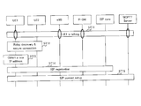
- FIG. 2 is a sequence chart illustrating an example of a switching operation of a UE wireless connection destination.
- FIG. 3 is a diagram illustrating an example of a UE protocol stack.
- FIG. 4 is a block diagram showing a configuration example of a UE according to Embodiment 1.
- FIG. 5 is a block diagram illustrating a configuration example of the MCPTT server according to the first embodiment.
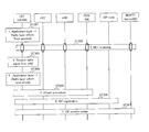
- FIG. 6 is a sequence chart showing an operation at the time of switching wireless connection destinations according to the first embodiment.
- FIG. 7 is a sequence chart showing an operation at the time of switching wireless connection destinations according to the first embodiment.
- FIG. 1 is a diagram illustrating an example of an architecture of a UE-to-Network relay in an MCPTT service.
- FIG. 2 is a sequence chart illustrating an example of a switching operation of a UE wireless connection destination.
- FIG. 8 is a block diagram illustrating a configuration example of a UE according to Embodiment 2.
- FIG. 9 is a sequence chart showing an operation at the time of switching wireless connection destinations according to the second embodiment.
- FIG. 10 is a block diagram illustrating a configuration example of a UE according to Embodiment 3.
- FIG. 11 is a sequence chart showing operations at the time of switching wireless connection destinations according to the third embodiment.
- FIG. 1 is a simplified diagram of a part of the UE-to-Network relay architecture in the MCPTT service described in Non-Patent Document 9. According to Non-Patent Document 9, there are elements that constitute the MCPTT service other than those shown in FIG. 1, but they are omitted here.
- the MCPTT server (MCPTT Server) shown in Fig.1 is a SIP (Session Initiation Protocol) application server function, a floor control server (Floor Control Server) function that controls the floor, and temporarily terminates the data from the speaker. It has MCPTT application server function to transfer to participants. In FIG. 1, for simplicity, it is assumed that these functions exist as part of the functions of the MCPTT server. However, these servers and functions are distributed to other nodes having different names. May exist.
- the SIP Core shown in FIG. 1 has a CSCF (Call Session Control Function) function described in Non-Patent Document 13 that performs routing of a SIP server or SIP signaling.
- CSCF Call Session Control Function
- Packet Core shown in FIG. 1 includes PCRF (Policy and Charging Rules Functions), P-GW (Packet Data Network Gateway), S-GW (Serving Gateway), MME (Mobility Management Entity) described in Non-Patent Document 10. ), ENB, and BM-SC (Broadcast Multicast Service Center), MBMS GW (MBMS Gateway) described in Non-Patent Document 12.
- PCRF Policy and Charging Rules Functions
- P-GW Packet Data Network Gateway
- S-GW Serving Gateway
- MME Mobility Management Entity
- ENB ENB
- BM-SC Broadcast Multicast Service Center
- MBMS GW MBMS Gateway
- UE1 and UE2 are currently participating in the MCPTT service.
- UE1 and UE2 are first directly wirelessly connected to the eNB via the Uu interface described in Non-Patent Document 11.
- UE1 obtains FloorFGrant from the MCPTT server and makes a statement (ST11). That is, UE1 transmits uplink data to the MCPTT server.
- the MCPTT server transmits data received from UE1 to other UEs participating in the same MCPTT service as UE1.
- UE1 When UE1 is likely to deviate from the eNB coverage area, UE1 performs relay UE discovery (Relay discovery), which is a relay UE detection process for UE1, via the PC5 interface described in Non-Patent Document 11 (ST12).
- relay UE discovery Relay discovery
- UE2 is discovered as a relay UE for UE1. Therefore, UE1 performs secure connection with UE2 through the PC5 interface (ST12). Further, UE1 performs wireless connection by obtaining an IP address used in a subnetwork under UE2 or information necessary for IP address generation from UE2 via the PC5 interface (ST13).
- UE1 uses the newly acquired or generated IP address to perform registration (SIP registration) via the PC5 interface with UE2 (SIP registration) (ST14). After that, UE1 performs Session Setup to start a session for MCPTT service (ST15). Through this Session Setup, a unicast bearer for UE1 under UE2 is newly established and a session is started.
- Session Setup is completed and a unicast bearer for UE1 under UE2 is established (for example, ST13 shown in FIG. 2).
- UE1 to ST15 UE1 does not transmit data to the MCPTT server. Therefore, the uplink data generated by UE1 in this period is discarded, and there is a problem that all UEs participating in the MCPTT service cannot receive data in this period. This problem also occurs when UE1 switches the wireless connection destination from UE2 to eNB.
- Non-Patent Document 14 or Non-Patent Document 15 By applying the technique described in Non-Patent Document 14 or Non-Patent Document 15 to the MCPTT service, there is a possibility that the amount of data discarded when the UE switches the wireless connection destination may be suppressed. However, in order to use the technology described in Non-Patent Document 14 or Non-Patent Document 15 in the MCPTT service, a large change is required not only for the UE but also for the packet-core node.
- one aspect of the present disclosure is that data that is discarded without changing to Packet Core even when the wireless connection destination is switched between the eNB and the relay UE while the UE transmits uplink data in MCPTT.
- the purpose is to reduce the amount of.
- the communication system according to the present embodiment employs the configuration shown in FIG.
- the communication system according to the present embodiment includes at least UE 100 (for example, UE 1 shown in FIG. 1) and MCPTT server 200 (communication node).
- UE 100 for example, UE 1 shown in FIG. 1
- MCPTT server 200 communication node.
- a UE for example, UE 100
- UE 100 that is given the right to speak transmits data to the MCPTT server 200, and other UEs other than the UE 100 The data is received from the MCPTT server 200.
- the MCPTT server 200 (MCPTT server shown in FIG. 1) has a SIP application server function, a floor control server function, an MCPTT application server function, and the like.
- SIP Core has CSCF functions and the like.
- Packet Core includes PCRF, P-GW, S-GW, eNB, BM-SC, MBMS GW, and the like.
- a plurality of UEs including UE1 (UE100) and UE2 participate in the MCPTT service through the architecture described above.
- UE2 communicates with SIPSCore or MCPTT server 200 through Packet Core by performing wireless connection with eNB through the Uu interface.
- UE1 directly connects to eNB via Uu interface, or uses UE2 as a relay UE (relay node), and wirelessly connects to UE2 via PC5 interface, thereby enabling SIP Core or MCPTT through Packet Core.
- Communication with the server 200 is performed. That is, UE1 transmits uplink data to MCPTT server 200 using either an on-Network service or a service using UE-to-Network relay.
- FIG. 3 shows an example of a protocol stack of the UE.
- the UE protocol stack consists of a radio layer, an intermediate layer, and an application layer.
- the wireless layer includes protocols such as PHY (Physical Layer), MAC (Medium Access Control), RLC (Radio Link Control), PDCP (Packet Data Convergence Protocol), RRC (Radio Resource Control) described in Non-Patent Document 11. , Data transmission and transmission / reception of signaling between the eNB and the UE, and the like, and a function of controlling wireless connection.
- protocols such as PHY (Physical Layer), MAC (Medium Access Control), RLC (Radio Link Control), PDCP (Packet Data Convergence Protocol), RRC (Radio Resource Control) described in Non-Patent Document 11. , Data transmission and transmission / reception of signaling between the eNB and the UE, and the like, and a function of controlling wireless connection.
- the intermediate layer includes a NAS (Non-Access Stratum) protocol described in Non-Patent Document 10, and has a function of transmitting and receiving signaling with Packet Core and controlling a bearer.
- the intermediate layer includes protocols such as IP (Internet Protocol), UDP (User Datagram Protocol), TCP (Transmission Control Protocol), RTP (Real-time Transport Protocol), etc., to send and receive application layer data It has necessary functions.
- the application layer includes SIP protocol, Floor Control protocol, etc., and has functions necessary for service control such as MCPTT, or functions necessary for data generation such as audio / video codec encoder / decoder.
- FIGS. 4 and 5 are block diagrams illustrating configuration examples of the UE 100 (for example, UE 1 illustrated in FIG. 1) and the MCPTT server 200, respectively. Note that the UE 100 and the MCPTT server 200 have functions as described in Non-Patent Documents 1 to 11 in addition to the configurations shown in FIGS. 4 and 5, but description thereof is omitted here.
- a wireless processing unit 101 includes a wireless processing unit 101, an API (Application Programming Interface) unit 102, a determination unit 103, a signaling generation unit 104, a storage unit 105, and a packet generation unit 106.
- API Application Programming Interface
- the wireless processing unit 101 belongs to the wireless layer
- the determination unit 103, the signaling generation unit 104, and the storage unit 105 belong to the application layer
- the packet generation unit 106 belongs to the intermediate layer or both the application layer and the intermediate layer. Belongs.
- the API unit 102 is an interface between the wireless layer and the application layer.
- the wireless processing unit 101 receives the IP packet and outputs signaling (radio layer information) included in the IP packet to the API unit 102. Further, the wireless processing unit 101 transmits a signaling or IP packet received from the API unit 102 or the packet generation unit 106.
- wireless processing part 101 judges whether UE100 is in the coverage area of eNB. For example, when the UE 100 is likely to be out of the eNB coverage area, the radio processing unit 101 determines execution of relay UE discovery (Relay discovery), and indicates information (radio layer information) indicating execution of relay UE discovery. Output to the API unit 102.
- relay UE discovery Relay discovery
- information radio layer information
- the API unit 102 outputs information on the wireless layer (for example, the wireless processing unit 101) to the application layer (for example, the determination unit 103), and outputs information on the application layer to the wireless layer (for example, the wireless processing unit 101).
- the determination unit 103 makes a determination regarding the application layer based on the wireless layer information received from the application layer or the API unit 102.
- the determination unit 103 determines whether the UE 100 switches the wireless connection destination between the eNB and the relay UE. Then, when the UE 100 switches the wireless connection destination, the determination unit 103 stops transmission of uplink data generated during switching of the wireless connection destination, and stores the uplink data in the storage unit 105 (buffering). Decide what to do. Further, the determination unit 103 determines to resume transmission of uplink data after completion of switching of wireless connection destinations (that is, after starting a session at the switching destination).
- the signaling generation unit 104 generates signaling based on the determination result of the determination unit 103. For example, when the determination unit 103 determines that the wireless connection destination is switched, the signaling generation unit 104 generates signaling for notifying the switching of the wireless connection destination. In other words, this signaling indicates that the UE 100 stops transmitting uplink data.
- the storage unit 105 buffers data generated in the application layer when the determination unit 103 determines to stop transmission of upstream data. Storage unit 105 also outputs buffered data to packet generation unit 106 when determination unit 103 determines to resume transmission of uplink data.
- the packet generation unit 106 converts the uplink data generated in the application layer or the data stored in the storage unit 105 and the signaling into an IP packet, and outputs the IP packet to the wireless processing unit 101.
- the MCPTT server 200 shown in FIG. 5 includes a reception unit 201, a transmission unit 202, a signaling processing unit 203, a determination unit 204, and a data processing unit 205.
- the receiving unit 201 receives the IP packet, outputs the signaling included in the IP packet to the signaling processing unit 203, and outputs the uplink data included in the IP packet to the data processing unit 205.
- the transmission unit 202 transmits an IP packet including signaling received from the signaling processing unit 203 or downlink data received from the data processing unit 205 to, for example, a plurality of UEs participating in the MCPTT service.
- the signaling processing unit 203 performs processing based on the content of signaling from the UE 100 or the like. Further, signaling processing section 203 generates signaling addressed to UE 100 and outputs it to transmitting section 202.
- the determination unit 204 determines processing based on the content of signaling processed by the signaling processing unit 203. For example, when receiving a signaling indicating switching of a wireless connection destination (or uplink data transmission stop) in the UE 100, the determination unit 204 determines that uplink data transmission from the UE 100 is temporarily stopped. In addition, the determination unit 204 determines that uplink data transmission from the UE 100 is resumed when a new session for the UE 100 is started after the uplink data transmission is stopped.
- the data processing unit 205 performs processing related to uplink data received from the reception unit 201 and downlink data for the UE based on the determination result of the determination unit 204.
- FIG. 6 is a sequence chart showing an example of switching operation of the wireless connection destination from the eNB subordinate of UE 100 to the relay UE (UE2) subordinate according to the present embodiment.
- UE1 (UE100) first wirelessly connects to the eNB via the Uu interface, and communicates with the SIP Core or the MCPTT server 200 via the Packet Core (eNB, PDN GW, etc.).
- UE1 obtains Floor® Grant from MCPTT server 200 and makes a statement (ST101). That is, UE1 transmits uplink data to MCPTT server 200.
- the MCPTT server 200 transmits the data received from UE1 to other UEs participating in the same MCPTT service as UE1.
- the UE1 radio layer radio processing unit 101
- the UE1 radio layer detects that UE1 is likely to be out of the eNB coverage area, it starts relay UE discovery (Relay discovery) via the PC5 interface described in Non-Patent Document 11. (ST102).
- the wireless layer (wireless processing unit 101) of UE1 outputs information indicating that Relay discovery is started (or started) to the application layer (determination unit 103) through the API unit 102 (ST103).
- UE1 determining section 103 generates an encoder (not shown) based on the information received from the radio layer in ST103 and the information indicating that UE1 has received Floor Grant in ST101 and is currently transmitting data. It decides to buffer the uplink data (for example, voice data) in the storage unit 105 until the session under the relay UE starts without transmitting it as IP packets.
- the determination unit 103 of the UE 100 determines to switch the wireless connection destination of the UE 100 when RelayRediscovery is started when the on-Network service is connected to the eNB, and the wireless connection destination Data generated during switching is buffered in the storage unit 105.
- the reception unit 201 of the MCPTT server 200 outputs the received signaling (Pause Request) to the signaling processing unit 203, and the signaling processing unit 203 outputs the content of the signaling to the determination unit 204.
- the determination unit 204 determines that from the UE1 until the UE1 completes switching of the wireless connection destination under the relay UE (that is, until the session under the relay UE starts). Determine that no data is sent. Therefore, determination section 204 instructs data processing section 205 to temporarily stop data reception processing and data transmission processing to other UEs participating in MCPTT services other than UE1 (ST105). ).
- the data processing unit 205 performs processing such as enlarging the size of the reception buffer (Buffer) or the transmission buffer on the assumption that data is transmitted collectively after resuming data transmission from UE1. May be.
- the storage unit 105 of UE1 starts buffering of encoded data (for example, an audio frame) (ST106).
- encoded data for example, an audio frame
- UE1 when UE2 is discovered as a relay UE, UE1 establishes Secure Connection between UE1 and UE2 (ST107). Moreover, UE1 acquires the IP address used in the sub-network under UE2 or information necessary for IP address generation from UE2 (ST107). UE1 generates an IP address using information necessary for IP address generation.
- UE1 registers with SIP Core via PC5 interface with UE2 using the IP address acquired or generated in ST107 (ST108).
- UE1 performs SIP Session Setup for starting a session for the MCPTT service after registration with SIP Core (ST109). Upon completion of SIP ⁇ ⁇ Session Setup, a new unicast bearer for UE1 under UE2 is established.
- the application layer (determination unit 103) of UE1 When the application layer (determination unit 103) of UE1 receives the SIP Session Setup completion message (for example, 200OK described in Non-Patent Document 13), the application layer (determination unit 103) determines that the unicast bearer for UE1 has been established. It instructs the buffering of upstream data to stop.
- the SIP Session Setup completion message for example, 200OK described in Non-Patent Document 13
- the storage unit 105 of the UE1 outputs the buffered data to the packet generation unit 106, and then sequentially outputs data newly generated by the encoder to the packet generation unit 106.
- the packet generation unit 106 converts the data received from the storage unit 105 into an IP packet using a new IP address (an IP address used under UE2).
- wireless processing section 101 transmits the IP packet to MCPTT server 200 (ST110). That is, the transmission processing unit 101 of UE1 transmits the data buffered in the storage unit 105 to the MCPTT server 200 after completion of switching of the wireless connection destination of UE1.
- the determination unit 204 of the MCPTT server 200 instructs the data processing unit 205 to cancel the suspension of data processing by transmitting a SIP Session Setup complete message to the UE1 in SIP session setup in ST109. That is, the determination unit 204 determines that data transmission from UE1 is resumed when switching of the wireless connection destination of UE1 is completed.
- UE100 when UE100 acquires or produces
- FIG. 7 is a sequence chart showing an example of switching operation of the wireless connection destination from the relay UE (UE2) subordinate to the eNB subordinate of UE100 according to the present embodiment.
- UE1 (UE100) first wirelessly connects to UE2 that is a relay UE via a PC5 interface, and communicates with SIP Core or MCPTT server 200 through Packet Core (eNB, PDN GW, etc.). .
- Packet Core Packet Core
- UE1 obtains a Floor TM Grant from the MCPTT server 200 and makes a statement (ST201). That is, UE1 transmits uplink data to MCPTT server 200.
- the MCPTT server 200 transmits the data received from UE1 to other UEs participating in the same MCPTT service as UE1.
- the radio layer (radio processing unit 101) of UE1 detects that UE1 is located in the coverage area of eNB, for example, based on a signal from eNB (ST202).
- the UE1 radio layer (radio processing unit 101) outputs information indicating that UE1 is within the eNB coverage area to the application layer (determination unit 103) through the API unit 102 (ST203).
- UE1 determining section 103 generates an encoder (not shown) based on the information received from the radio layer in ST203 and information indicating that UE1 has received a Floor-Grant and is currently transmitting data in ST201. It decides to buffer the uplink data (for example, voice data) in the storage unit 105 until the session under the eNB starts without transmitting the packetized IP packet.
- the determination unit 103 of the UE 100 when connected to the relay UE and using a service using a UE-to-Network relay, receives a signal from the eNB (for example, RSRP (Reference in Non-Patent Document 11). It is determined that the wireless connection destination of the UE 100 is switched by detecting signal (received power) and RSRQ (Reference signal received quality)), and data generated during switching of the wireless connection destination is buffered in the storage unit 105.
- RSRP Reference in Non-Patent Document 11
- the reception unit 201 of the MCPTT server 200 outputs the received signaling (Pause Request) to the signaling processing unit 203, and the signaling processing unit 203 outputs the content of the signaling to the determination unit 204.
- the determination unit 204 receives data from UE1 until UE1 completes switching of wireless connection destinations under the eNB (that is, until a session under the eNB starts). Judge that it is not sent. Therefore, determination section 204 instructs data processing section 205 to temporarily stop data reception processing and data transmission processing to other UEs participating in MCPTT services other than UE1 (ST205). ).
- the data processing unit 205 performs processing such as enlarging the size of the reception buffer (Buffer) or the transmission buffer on the assumption that data is transmitted collectively after resuming data transmission from UE1. May be.
- the storage unit 105 of UE1 starts buffering of encoded data (for example, an audio frame) (ST206).
- encoded data for example, an audio frame
- UE1 stops the communication between UE1 and UE2 when the strength or quality of the radio signal from the eNB exceeds the reference value, and starts the Attach process described in Non-Patent Document 10 (ST207).
- UE1 acquires or generates an IP address used under the eNB.
- UE1 originally holds the IP address used under eNB, and relinquishes the IP address used under UE2, so that the IP address used under eNB can be used again. In some cases.
- it is used under the eNB when processing the IP address to be used (whether it is acquired / generated or using a fixed one) or when the UE moves from the eNB subordinate to the relay UE.
- the bearer processing (Detach processing or S1 Release processing described in Non-Patent Document 10)
- the UE performs Service Request processing instead of Attach processing.
- UE1 registers with SIP Core through the Uu interface with eNB using the IP address acquired or generated in ST207 (ST208).
- UE1 performs SIP Session Setup to start a session for the MCPTT service after registration with SIP Core (ST209). Upon completion of SIP Session Setup, a unicast bearer for UE1 under the eNB is newly established.
- the application layer (determination unit 103) of UE1 When the application layer (determination unit 103) of UE1 receives the SIP Session Setup completion message (for example, 200OK described in Non-Patent Document 13), the application layer (determination unit 103) determines that the unicast bearer for UE1 has been established. It instructs the buffering of upstream data to stop.
- the SIP Session Setup completion message for example, 200OK described in Non-Patent Document 13
- the storage unit 105 of the UE1 outputs the buffered data to the packet generation unit 106, and then sequentially outputs data newly generated by the encoder to the packet generation unit 106.
- the packet generation unit 106 converts the data received from the storage unit 105 into an IP packet using a new IP address (an IP address used under the eNB).
- radio processing section 101 transmits the IP packet to MCPTT server 200 (ST210). That is, the transmission processing unit 101 of UE1 transmits the data buffered in the storage unit 105 to the MCPTT server 200 after completion of switching of the wireless connection destination of UE1.
- the determination unit 204 of the MCPTT server 200 instructs the data processing unit 205 to cancel the suspension of data processing by transmitting a SIP Session Setup complete message to the UE1 in SIP session setup in ST209. That is, the determination unit 204 determines that data transmission from UE1 is resumed when switching of the wireless connection destination of UE1 is completed.
- the UE 100 acquires or generates an IP address to be used under the eNB when switching the wireless connection destination from the relay UE subordinate to the eNB subordinate, until the session under the eNB starts.
- the UE 100 stops transmission of uplink data generated during a period in which the UE 100 cannot communicate, and performs buffering. And UE100 will transmit the buffered data to the MCPTT server 200, if the session under eNB is started.
- the communication system when UE 100 to which a floor is given switches the wireless connection destination between the eNB and the relay UE, data generated during switching of the wireless connection destination. And the buffered data is transmitted to the MCPTT server 200 after switching of the wireless connection destination is completed.
- the UE 100 as the transmission source temporarily stores and transmits uplink data generated when the wireless connection destination of the UE 100 is switched. That is, only the transmission timing of data in the UE 100 is shifted, and there is no need to change the setting or configuration in the Packet Core node.
- the UE even when switching the wireless connection destination between the eNB and the relay UE during the uplink data transmission in the MCPTT, the UE discards without changing to Packet ⁇ ⁇ Core. The amount of data that can be reduced.
- UE 100 transmits signaling indicating buffering to MCPTT server 200 without transmitting uplink data.
- the MCPTT server 200 can prevent erroneous recognition that an error has occurred even when uplink data from the UE 100 cannot be received for a predetermined period.
- the MCPTT service unilateral data transmission is performed from the UE of the speaking user to another UE. Therefore, even when UE 100 that participates in the MCPTT service transmits buffered data after switching the wireless connection destination as in the present embodiment, the influence on other UEs that receive the data is small. For example, when the MCPTT server 200 holds a certain amount of data from the UE 100 and distributes the data to other UEs, the delay caused by transmitting the buffered data of the UE 100 after switching the wireless connection destination is absorbed. Is done.
- signaling indicating that transmission of uplink data is stopped may not be notified from the UE 100 to the MCPTT server 200.
- the packet generation unit 106 of UE1 may combine the buffered data into one IP packet and output it to the wireless processing unit 101, or sequentially convert several frames into one IP packet to the wireless processing unit 101.
- One frame may be sequentially output to the wireless processing unit 101 as one IP packet.
- the packet generation unit 106 may narrow the interval at which the IP packet is output to the wireless processing unit 101.
- the packet generator 106 normally outputs an IP packet every 20 msec, but may output an IP packet including buffered data at a frequency of 20 msec or less.
- the data processing unit 205 of the MCPTT server 200 is, for example, normally one frame per packet, but several frames become one packet. If it is, this packet may be converted into a normal format of one packet and one frame and transmitted to other UEs participating in the MCPTT service other than UE1.
- the API layer 102 when the application layer of UE 100 (UE1) is given Floor Grant, the API layer 102 notifies the radio layer that the Floor Grant is given, and the radio layer sends the Floor Grant. Only when the switching of the wireless connection destination occurs while being given, notification of the switching of the wireless connection destination occurring to the application layer of UE1 (for example, ST103 shown in FIG. 6, ST203 shown in FIG. 7) May be.
- Embodiment 2 ⁇ Transfer from UE's relay UE subordinate to eNB subordinate>
- the case has been described in which the UE buffers data in the application layer and transmits after switching (see FIG. 7) when the UE switches the wireless connection destination from the relay UE subordinate to the eNB subordinate.
- this Embodiment demonstrates the method of not performing an Attach process or a Service Request process until the user's speech of UE is complete
- FIG. 8 is a block diagram showing a configuration example of UE 300 (UE 1 shown in FIG. 1) according to the present embodiment.
- the same components as those of UE 100 (FIG. 6) of Embodiment 1 are denoted by the same reference numerals, and the description thereof is omitted.
- the configuration of the MCPTT server 200 is the same as that of the first embodiment (FIG. 5), and the description thereof is omitted.
- the radio processing unit 101 and the determination unit 301 belong to the radio layer.
- the determination unit 301 makes a determination regarding the wireless layer based on the application layer information received from the wireless layer or the API unit 102.
- the radio processing unit 101 of the UE 300 returns to the coverage area of the eNB.
- the determination unit 301 determines to start switching the wireless connection destination (Attach process or Service request process) after the uplink data transmission of the UE 300 is completed (speaking ends).
- the wireless connection destination switching unit 302 executes wireless connection destination switching (for example, an Attach process or a Service request process) based on the determination result of the determination unit 301.
- FIG. 9 is a sequence chart illustrating an operation example of switching wireless connection destinations from the relay UE (UE2) subordinate to the eNB subordinate of UE 300 according to the present embodiment.
- UE1 (UE300) first wirelessly connects with UE2 that is a relay UE via a PC5 interface, and performs communication with SIP Core or MCPTT server 200 through Packet Core (eNB, PDN GW, etc.). .
- Packet Core Packet Core
- UE1 obtains Floor® Grant from MCPTT server 200.
- API section 102 of UE1 outputs information indicating that UE1 has been given Floor Grant from the application layer to the wireless layer (determination section 301) (ST301). It should be noted that, from the application layer to the wireless layer, information indicating that Floor Grant has been given and the time during which Floor Grant is granted (upper limit of time for which speech can be made) may be output.
- UE1 speaks via UE2 (ST302). That is, UE1 transmits uplink data to MCPTT server 200.
- the MCPTT server 200 transmits the data received from UE1 to other UEs participating in the same MCPTT service as UE1.
- the radio layer (radio processing unit 101) of UE1 detects that UE1 is located in the coverage area of eNB, for example, based on a signal from eNB (ST303).
- the radio layer (determination section 301) of UE1 performs data transmission (speaking) while the right to speak is given based on the detection result in ST303 and the information indicating that UE1 has received Floor Grant in ST301. ) Is terminated, it is determined not to switch the wireless connection destination under the eNB, and information indicating that the wireless connection destination is not switched is output to the wireless connection destination switching unit 302. For example, the determination unit 301 instructs the wireless connection destination switching unit 302 not to transmit the Random Access request and RRC Connection Establishment request described in Non-Patent Document 11 or the like to the eNB.
- the API section 102 of UE1 When UE1's utterance ends, the API section 102 of UE1 outputs information indicating that the UE's utterance has ended from the application layer to the wireless layer (determination section 301) (ST304).
- the determination part 301 has received the time (the upper limit of the time which can be said) in which Floor Grant was permitted in ST301, based on the said permission time, you may determine the speech end of UE1. In this case, the process of ST304 becomes unnecessary.
- the determination unit 301 of the UE1 determines to switch the wireless connection destination under the eNB, and instructs the wireless connection destination switching unit 302 to start switching the wireless connection destination.
- the wireless connection destination switching unit 302 transmits a Random Access request and an RRC Connection Establishment request described in Non-Patent Document 11 or the like to the eNB.
- UE1 switches a radio
- the Attach process or the Service request process the UE 1 acquires or generates an IP address used under the eNB.
- UE1 originally holds the IP address used under eNB, and relinquishes the IP address used under UE2, so that the IP address used under eNB can be used again. In some cases.
- UE1 registers with SIP Core through the Uu interface with eNB using the IP address acquired or generated in ST305 (ST306).
- UE1 performs SIP Session Setup for starting a session for the MCPTT service after registration with SIP Core (ST307). Upon completion of SIP Session Setup, a unicast bearer for UE1 under the eNB is newly established.
- the wireless layer (determination unit 301) adjusts the wireless connection destination switching timing based on the information output from the application layer to the wireless layer. Specifically, the UE 300 under the relay UE can switch the wireless connection destination from the relay UE subordinate to the eNB subordinate while the Floor ⁇ Grant is given (or until the remark ends). Suspends switching of the wireless connection destination. That is, the UE 300 switches the wireless connection destination after the utterance by the floor-grant currently given is finished.
- the uplink data from the UE 300 to the MCPTT server 200 is transmitted without being discarded before the wireless connection destination is switched. Therefore, UEs participating in the MCPTT service can receive uplink data generated by UE1 when UE1 wireless connection destination is switched.
- the UE 300 wireless connection destination switching timing is only shifted after completion of uplink data transmission, and there is no need to change the setting or configuration in the Packet Core node.
- the UE even when switching the wireless connection destination between the eNB and the relay UE during the uplink data transmission in the MCPTT, the UE discards without changing to Packet ⁇ ⁇ Core. The amount of data that can be reduced.
- Non-Patent Document 10 when UE300 (UE1) receives downlink data from the MCPTT server 200 using an MBMS bearer, the Tracking described in Non-Patent Document 10 is used instead of the Attach process or the Service request process of ST305. Area Update processing may be performed. In this case, the registration to the SIP Core in ST306 and the Session Setup process in ST307 are omitted.
- Embodiment 3 ⁇ Transfer from eNB subordinate to UE under relay UE>
- the case where the UE buffers data in the application layer when the UE switches the wireless connection destination from the eNB subordinate to the relay UE, and transmits the data after the switching (see FIG. 7) has been described.
- the IP address or IP address under the relay UE A method of not performing (delaying) information necessary for generation as much as possible (until just before disconnection from the eNB) is described.
- FIG. 10 is a block diagram showing a configuration example of UE 400 (UE 1 shown in FIG. 1) according to the present embodiment.
- UE 400 UE 1 shown in FIG. 1
- the same components as those of UE 100 (FIG. 6) of Embodiment 1 are denoted by the same reference numerals, and the description thereof is omitted.
- the configuration of the MCPTT server 200 is the same as that of the first embodiment (FIG. 5), and the description thereof is omitted.
- the wireless processing unit 101 and the determination unit 401 belong to the wireless layer.
- the determination unit 401 when the determination unit 401 receives information indicating that the user of the UE 400 has been given a right to speak from the application layer, the eNB indicates that the radio processing unit 101 of the UE 400 is about to deviate from the eNB coverage area. If it is detected by a signal from the relay UE, it establishes a secure UE connection with the discovered relay UE, but decides not to acquire an IP address under the relay UE or information necessary for IP address generation . In addition, the determination unit 401 detects that the radio processing unit 101 of the UE 400 is immediately before disconnection from the eNB from the signal from the eNB (for example, the strength of the signal from the eNB is weaker than a threshold value, etc. If it is detected by the method), it is determined that it is necessary to obtain an IP address under the relay UE or information necessary for IP address generation.
- the wireless connection destination switching unit 402 switches the wireless connection destination based on the determination result of the determination unit 401 (for example, discovery of relay UE, establishment of secure connection with the discovered relay UE, IP address or IP address under the relay UE) Acquisition of information necessary for generation).
- FIG. 11 is a sequence chart showing an example of switching operation of the wireless connection destination from the eNB subordinate of the UE 400 to the subordinate of the relay UE according to the present embodiment.
- UE1 (UE400) first wirelessly connects to the eNB via the Uu interface, and performs communication with the SIP Core or the MCPTT server 200 via the Packet Core (eNB, PDN GW, etc.).
- UE1 obtains Floor® Grant from MCPTT server 200.
- the API unit 102 of UE1 outputs information indicating that UE1 has been given Floor Grant from the application layer to the wireless layer (determination unit 401) (ST401). It should be noted that, from the application layer to the wireless layer, information indicating that Floor Grant has been given and the time during which Floor Grant is granted (upper limit of time for which speech can be made) may be output.
- UE1 speaks via eNB (ST402). That is, UE1 transmits uplink data to MCPTT server 200.
- the MCPTT server 200 transmits the data received from UE1 to other UEs participating in the same MCPTT service as UE1.
- the UE1 radio layer radio processing unit 101 detects that UE1 is likely to be out of the eNB coverage area based on a signal from the eNB, for example, via the PC5 interface described in Non-Patent Document 11 And start relay UE discovery (RelayUEdiscovery) (ST403).
- the radio layer of UE1 (determination section 401) establishes Secure Connection with the relay UE discovered in ST403 based on the information indicating that UE1 has received the Floor Grant in ST401 (ST404). However, the determination unit 401 determines that the IP address under the relay UE or information necessary for IP address generation is not acquired at this time.
- the UE1 wireless layer detects that the connection with the eNB is about to be cut off, for example, because the signal from the eNB is weaker than a threshold (ST405).
- the radio layer (radio processing unit 101) of UE1 confirms information from the application layer of the radio layer (determination unit 401), and when the user of UE 400 is speaking, the application unit passes through the API unit 102.
- Information indicating that Relay discovery is started (or started) is output to the layer (determination unit 103) (ST406), and the IP address under the relay UE or information necessary for IP address generation is acquired. (ST407).
- the UE 400 performs switching of the wireless connection destination from the subordinate of the eNB to the subordinate of the relay UE immediately before the connection with the eNB is disconnected. Thereby, UE400 can perform the transmission of the uplink data to MCPTT server 200 under eNB as much as possible.
- UE 400 stops transmission of uplink data generated in a period in which UE 400 cannot communicate, buffers, and relays to relay UE, as in Embodiment 1.
- the buffered data is transmitted to the MCPTT server 200.
- data that cannot be transmitted by the UE 400 due to switching of the wireless connection destination is not discarded, and is transmitted to the MCPTT server 200 after the start of a new session after switching. Therefore, UEs participating in the MCPTT service can receive uplink data when the wireless connection destination of UE 400 is switched.
- the MCPTT server 200 receives other UEs (other than UE1) participating in the MCPTT service during the suspension process of ST105 (FIGS. 6 and 11) and ST205 (FIG. 7).
- a packet indicating a silent period (DTX: “Discontinuous” Transmission) may be transmitted to the UE).
- Non-Patent Document 16 describes DTX.
- MCPTT has been described as an example.
- the present invention may be applied to other services using a similar architecture.
- each functional block used in the description of the above embodiments is typically realized as an LSI that is an integrated circuit having an input terminal and an output terminal.
- the integrated circuit may control each functional block used in the description of the above embodiment, and may include an input terminal and an output terminal. These may be individually made into one chip, or may be made into one chip so as to include a part or all of them.
- the name used here is LSI, but it may also be called IC, system LSI, super LSI, or ultra LSI depending on the degree of integration.
- the method of circuit integration is not limited to LSI, and may be realized by a dedicated circuit or a general-purpose processor.
- An FPGA Field Programmable Gate Array
- a reconfigurable / processor that can reconfigure the connection or setting of circuit cells inside the LSI may be used.
- One embodiment of the present disclosure is useful for a communication system that provides MCPTT service and a user terminal that uses the communication system.
Landscapes
- Engineering & Computer Science (AREA)
- Computer Networks & Wireless Communication (AREA)
- Signal Processing (AREA)
- Multimedia (AREA)
- Business, Economics & Management (AREA)
- General Business, Economics & Management (AREA)
- Mobile Radio Communication Systems (AREA)
Abstract
複数の端末のうち、発言権を与えられたUE(100)がデータをMCPTTサーバ(200)に送信し、UE(100)以外の端末がMCPTTサーバ(200)から当該データを受信する通信システムであって、UE(100)は、基地局と無線接続してMCPTTサーバ(200)との通信を行う第1のサービス、及び、リレー端末と無線接続してMCPTTサーバ(200)との通信を行う第2のサービスのいずれかを使用する。UE(100)は、第1のサービスを使用中に基地局からリレー端末に無線接続先を切り替える場合に、または、第2のサービスを使用中にリレー端末から基地局に無線接続先を切り替える場合に、無線接続先の切替中に生成されるデータをバッファリングし、無線接続先の切替完了後に、バッファリングされたデータをMCPTTサーバ(200)へ送信する。
Description
本開示は、通信システム、端末及び通信制御方法に関する。
現在、3GPP(3rd Generation Partnership Project)において、MCPTT(Mission Critical Push To Talk)の標準化が進められている。
非特許文献1には、MCPTTのサービス及びシステムの詳細を策定する上での要求条件が記載されている。非特許文献1によると、MCPTTのサービスとしては、on-networkサービス、off-networkサービス、又は、on-networkサービス及びoff-networkサービスの両方を使用したサービスが考えられている。
on-networkサービスは、GCSE_LTE(Group Communication System Enablers for LTE:例えば、非特許文献2及び非特許文献3を参照)を使用したサービスである。非特許文献2及び非特許文献3によると、GCSE_LTEを用いた通信では、MCPTT等のグループサービスに参加している各端末(UE:User Equipment)に対して、非特許文献10又は非特許文献11に記載のEPS(Evolved Packet System)ベアラを用いたユニキャスト通信を行ってもよく、非特許文献12に記載のMBMS(Multimedia Broadcast and Multicast Service)ベアラを用いたMBMS通信を行ってもよい。
また、off-networkサービスは、端末間直接通信であるProSe(Proximity Services:例えば、非特許文献4、非特許文献5、非特許文献6、非特許文献7を参照)を使用したサービスである。Prose通信は、サイドリンク(Sidelink)通信と呼ばれることもある。
On-networkサービス及びoff-networkサービスの両方を使用したサービスとして、例えば、非特許文献1,非特許文献6,非特許文献9などに記載されているUE-to-Networkリレー(relay)を使用したサービスがある。UE-to-Networkリレーを使用したサービスとは、基地局(eNB:eNode B)のカバレッジ(coverage)内に存在するUEが、eNBのカバレッジ外に存在するUE(リモート(remote)UE)とEPSとの通信を中継するリレー(relay)UEとして機能するサービスである。このサービスでは、リレーUEとリモートUEとの間ではProSe通信を用いたoff-networkサービスが行われ、リレーUEとEPC(EPC: Evolved Packet Core,以下 Packet Coreとも記述する)との間ではGCSE_LTEを用いたon-networkサービスが行われる。このリレーUEは、Layer 3リレー、つまり、リモートUEにとってのLayer 3ルータとして機能する。
また、非特許文献1によると、MCPTTサービスの提供を受けるユーザのUEは、MCPTTサービスのグループに所属する。UEが所属するグループは同時に複数であってもよい。
MCPTTサービスでは、発言権制御(Floor Control)をサポートすることが要求されており、グループ内で発言権(Floor grant)を与えられたユーザのみが発言することが許される。また、この発言権が与えられる時間に制限をつけてもよい。また、緊急事態発生時などには、優先割込み(Pre-emption)を許可することが要求されている。優先割込みが発生した場合には、現行のMCPTTサービスは一時中断され、発言権を優先割込みに譲る。非特許文献8及び非特許文献9には、MCPTTサービスグループへの登録、発言権制御、ネットワークへのリソース割当などを含むMCPTTサービスのアーキテクチャ(architecture)及びシグナリング(signaling)の例が開示されている。
また、非特許文献9によると、UEからMCPTTサーバ(後述する)に送られる上りのメディアデータ(音声・動画など。以下、「データ」と称する)に関しては、前述のユニキャスト通信が用いられるが、MCPTTサーバからUEに送られる下りのデータに関してはユニキャスト通信を用いてもよく、MBMS通信を用いてもよく、その両方を用いてもよい。
3GPP TS 22.179 v13.3.0、 "Mission Critical Push to Talk (MCPTT) over LTE; Stage 1"
3GPP TS 22.468 v13.0.0、 "Group Communication System Enablers for LTE (GCSE_LTE)"
3GPP TS 23.468 v13.3.0、 "Group Communication System Enablers for LTE (GCSE_LTE); Stage 2"
3GPP TS 22.278 v13.2.0、 "Service requirements for the Evolved Packet System (EPS)"
3GPP TR 23.713 v13.0.0、 "Study on extended architecture support for proximity services"
3GPP TS 23.303 v13.2.0、 "Proximity-based services (ProSe); Stage 2"
3GPP TS 36.321 v12.6.0、 "Evolved Universal Terrestrial Radio Access (E-UTRA); Medium Access Control (MAC) protocol specification"
3GPP TR 23.779 v13.0.0、 "Study on application architecture to support Mission Critical Push To Talk over LTE (MCPTT) services"
3GPP TS 23.179 v13.0.0、 "Functional architecture and information flows to support mission critical communication services; Stage 2"
3GPP TS 23.401 v13.5.0、 "General Packet Radio Service (GPRS) enhancements for Evolved Universal Terrestrial Radio Access Network (E-UTRAN) access"
3GPP TS 36.300 v13.2.0、 "Evolved Universal Terrestrial Radio Access (E-UTRA) and Evolved Universal Terrestrial Radio Access Network (E-UTRAN); Overall description; Stage 2"
3GPP TS 23.246 v13.3.0、 "Multimedia Broadcast/Multicast Service (MBMS); Architecture and functional description"
3GPP TS 23.228 v13.4.0 "IP Multimedia Subsystem (IMS); Stage 2"
IETF RFC 5944, "IP Mobility Support for IPv4, Revised"
IETF RFC 6275, "Mobility Support in IPv6"
3GPP TS 26.092 v13.0.0 "Mandatory speech codec speech processing functions; Adaptive Multi-Rate (AMR) speech codec; Comfort noise aspects"
UEがeNBのカバレッジエリア内外を移動すると、当該UEの無線接続先はeNBとリレーUEとの間で切り替わる。ところで、発言権が与えられて発言中のユーザのUEの無線接続先が切り替わる場合、切替後の新たなセッションが開始するまでの間、UEはMCPTTサーバへデータを送信することができない。よって、発言権を与えられたUEの無線接続先を切り替える場合には当該UEからMCPTTサーバへの上りのデータは破棄されてしまい、MCPTTサービスに参加する他のUEにはデータが届かないという課題が生じる。
本開示の一態様は、UEの無線接続先を切り替える場合でも破棄されるデータ量を抑えることができる通信システム、端末及び通信制御方法を提供することである。
本開示の一態様に係る通信システムは、複数の端末のうち、発言権を与えられた第1の端末がデータを通信ノードに送信し、前記第1の端末以外の第2の端末が前記通信ノードから当該データを受信する通信システムであって、前記第1の端末は、基地局と無線接続して前記通信ノードとの通信を行う第1のサービス、及び、リレー端末と無線接続して前記通信ノードとの通信を行う第2のサービスのいずれかを使用し、前記第1の端末は、前記第1のサービスを使用中に前記基地局から前記リレー端末に無線接続先を切り替える場合に、または、前記第2のサービスを使用中に前記リレー端末から前記基地局に無線接続先を切り替える場合に、前記無線接続先の切替中に生成される前記データをバッファリングし、前記無線接続先の切替完了後に、前記バッファリングされたデータを前記通信ノードへ送信する。
本開示の一態様に係る通信システムは、複数の端末のうち、発言権を与えられた第1の端末がデータを通信ノードに送信し、前記第1の端末以外の第2の端末が前記通信ノードから当該データを受信する通信システムであって、前記第1の端末は、基地局と無線接続して前記通信ノードとの通信を行う第1のサービス、及び、リレー端末と無線接続して前記通信ノードとの通信を行う第2のサービスのいずれかを使用し、前記第1の端末は、前記基地局と前記リレー端末との間で無線接続先を切り替える場合、前記発言権が与えられている間のデータ送信が完了するまで前記無線接続先の切替を行わず、前記データの送信完了後に前記無線接続先の切替を行う。
本開示の一態様に係る端末は、基地局と無線接続して通信ノードとの通信を行う第1のサービス、及び、リレー端末と無線接続して前記通信ノードとの通信を行う第2のサービスのいずれかを使用して、データを前記通信ノードに送信する無線処理部と、データをバファリングする格納部と、前記通信ノードから発言権を取得した場合であって、前記第1のサービスを使用中に前記基地局から前記リレー端末に無線接続先を切り替える場合に、または、前記第2のサービスを使用中に前記リレー端末から前記基地局に無線接続先を切り替える場合に、前記無線接続先の切替中に生成される前記データを前記格納部にバッファリングすると判断する判断部と、を具備し、前記無線処理部は、前記無線接続先の切替完了後に、前記バッファリングされたデータを前記通信ノードへ送信する。
本開示の一態様に係る通信制御方法は、複数の端末のうち、発言権を与えられた第1の端末がデータを通信ノードに送信し、前記第1の端末以外の第2の端末が前記通信ノードから当該データを受信する通信システムにおける通信制御方法であって、前記第1の端末において、基地局と無線接続して前記通信ノードとの通信を行う第1のサービス、及び、リレー端末と無線接続して前記通信ノードとの通信を行う第2のサービスのいずれかが使用され、前記第1の端末において、前記第1のサービスを使用中に前記基地局から前記リレー端末に無線接続先を切り替える場合に、または、前記第2のサービスを使用中に前記リレー端末から前記基地局に無線接続先を切り替える場合に、前記無線接続先の切替中に生成される前記データをバッファリングし、前記無線接続先の切替完了後に、前記バッファリングされたデータを前記通信ノードへ送信する。
なお、これらの包括的または具体的な態様は、システム、装置、方法、集積回路、コンピュータプログラム、または、記録媒体で実現されてもよく、システム、装置、方法、集積回路、コンピュータプログラムおよび記録媒体の任意な組み合わせで実現されてもよい。
本開示の一態様によれば、UEの無線接続先を切り替える場合でも破棄されるデータ量を抑えることができる。
本開示の一態様における更なる利点および効果は、明細書および図面から明らかにされる。かかる利点および/または効果は、いくつかの実施形態並びに明細書および図面に記載された特徴によってそれぞれ提供されるが、1つまたはそれ以上の同一の特徴を得るために必ずしも全てが提供される必要はない。
(本開示に至る経緯)
まず、本開示に至る経緯について説明する。
まず、本開示に至る経緯について説明する。
図1は、非特許文献9に記載のMCPTTサービスにおけるUE-to-Networkリレーのアーキテクチャ(architecture)の一部を簡略化した図である。なお、非特許文献9によれば、図1に示す以外にもMCPTTサービスを構成する要素は存在するが、ここでは省略する。
図1に示すMCPTTサーバ(MCPTT Server)は、SIP(Session Initiation Protocol)アプリケーションサーバ機能、発言権制御を行う発言権制御サーバ(Floor Control Server)機能、発言者からのデータを一旦終端し、MCPTTサービス参加者に転送するMCPTTアプリケーションサーバ機能などを有する。なお、図1では、図の簡略化のため、これらの機能をMCPTTサーバの機能の一部として存在すると仮定しているが、これらのサーバ及び機能は別の名称を持つ他のノードに分散して存在してもよい。
また、図1に示すSIP Coreは、SIPサーバ又はSIPシグナリングのルーティングなどを行う、非特許文献13に記載のCSCF(Call Session Control Function)の機能などを有する。
また、図1に示すPacket Coreは、非特許文献10に記載の、PCRF(Policy and Charging Rules Function)、P-GW(Packet Data Network Gateway)、S-GW(Serving Gateway)、MME(Mobility Management Entity)、eNB、非特許文献12に記載の、BM-SC(Broadcast Multicast Service Center)、MBMS GW(MBMS Gateway)などを有する。
次に、図1及び図2を参照して、Floor Grantを得て発言中のユーザのUEがeNB配下からリレーUE配下へ無線接続先を切り替える場合の手順を説明する。本手順は非特許文献6及び非特許文献9などに基づく。
現在、UE1及びUE2を含む複数のUE(不図示)がMCPTTサービスに参加しているとする。また、UE1及びUE2は、最初、非特許文献11に記載のUuインタフェースを介して、eNBと直接無線接続している。
図2では、UE1は、MCPTTサーバからFloor Grantを得て、発言を行う(ST11)。すなわち、UE1は、MCPTTサーバに対して上りのデータを送信する。MCPTTサーバは、UE1と同じMCPTTサービスに参加している他のUEに対して、UE1から受信したデータを送信する。
UE1がeNBのカバレッジエリアから外れそうになると、UE1は、非特許文献11に記載のPC5インタフェースを介して、UE1に対するリレーUEの検出処理であるリレーUE発見(Relay discovery)を行う(ST12)。図2では、UE2がUE1に対するリレーUEとして発見される。そこで、UE1は、PC5インタフェースを介してUE2とsecure connectionを行う(ST12)。また、UE1は、UE2よりPC5インタフェースを介してUE2配下のサブネットワークで使用するIPアドレス又はIPアドレス生成に必要な情報を取得することにより無線接続を行う(ST13)。
UE1は、新しく取得又は生成したIPアドレスを使用して、UE2とのPC5インタフェースを介してSIP Coreに登録(SIP registration)を行う(ST14)。その後、UE1は、MCPTTサービスのためのセッションを開始するために、Session Setupを行う(ST15)。このSession Setupによって、UE2配下のUE1用のユニキャストベアラが新たに確立され、セッションが開始される。
ここで、UE1がUE2配下で使用するIPアドレスを取得又は生成してから、Session Setupが完了し、UE2配下のUE1用のユニキャストベアラが確立されるまでの間(例えば、図2に示すST13~ST15の間)、UE1はデータをMCPTTサーバへ送信することがでない。よって、この期間においてUE1で生成される上りのデータは破棄され、MCPTTサービスに参加する全てのUEはこの期間におけるデータを受信できないという課題が生じる。この課題は、UE1がUE2配下からeNB配下への無線接続先の切替時にも同様に生じる。
ところで、UEの移動によるIPアドレスの変更後も、変更前のIPアドレスを利用し続ける技術として、非特許文献14又は非特許文献15に記載のMobile IPがある。非特許文献14又は非特許文献15に記載の技術をMCPTTサービスに適用することで、UEが無線接続先を切り替える際に破棄されるデータの量を抑えることができる可能性がある。しかしながら、MCPTTサービスにおいて非特許文献14又非特許文献15に記載の技術を用いるためには、UEのみでなくPacket Coreのノードにも大きな変更が必要となる。
そこで、本開示の一態様は、MCPTTにおいてUEが上りデータ送信中に、eNBとリレーUEとの間で無線接続先を切り替える場合においても、Packet Coreへの変更を加えることなく、破棄されるデータの量を抑えることを目的とする。
以下、本開示の各実施の形態について、図面を参照して詳細に説明する。
(実施の形態1)
以下、図1及び図3~図6を用いて、本実施の形態におけるUEの無線接続先切替方法について説明する。
以下、図1及び図3~図6を用いて、本実施の形態におけるUEの無線接続先切替方法について説明する。
[通信システムの構成]
本実施の形態に係る通信システムは、図1に示す構成を採る。本実施の形態に係る通信システムは、少なくとも、UE100(例えば、図1に示すUE1)及びMCPTTサーバ200(通信ノード)を備える。本実施の形態に係る通信システムでは、MCPTTサービスに参加する複数のUEのうち、発言権を与えられたUE(例えば、UE100)がデータをMCPTTサーバ200に送信し、UE100以外の他のUEがMCPTTサーバ200から当該データを受信する。
本実施の形態に係る通信システムは、図1に示す構成を採る。本実施の形態に係る通信システムは、少なくとも、UE100(例えば、図1に示すUE1)及びMCPTTサーバ200(通信ノード)を備える。本実施の形態に係る通信システムでは、MCPTTサービスに参加する複数のUEのうち、発言権を与えられたUE(例えば、UE100)がデータをMCPTTサーバ200に送信し、UE100以外の他のUEがMCPTTサーバ200から当該データを受信する。
本実施の形態におけるMCPTTサービスのアーキテクチャ及び前提条件は前述の通りである。すなわち、MCPTTサーバ200(図1に示すMCPTT Server)は、SIPアプリケーションサーバ機能、発言権制御サーバ機能、MCPTTアプリケーションサーバ機能などを有する。また、SIP Coreは、CSCFの機能などを有する。また、Packet Coreは、PCRF、P-GW、S-GW、eNB、BM-SC、MBMS GWなどを有する。
また、本実施の形態において前提となるシナリオでは、UE1(UE100)、UE2を含む複数のUE(不図示)が前述のアーキテクチャを通じてMCPTTサービスに参加している。UE2は、Uuインタフェースを介してeNBと無線接続を行うことにより、Packet Coreを通じてSIP Core又はMCPTTサーバ200との通信を行う。また、UE1は、Uuインタフェースを介してeNBと直接無線接続するか、又は、UE2をリレーUE(リレーノード)として、PC5インタフェースを介してUE2と無線接続することにより、Packet Coreを通じてSIP Core又はMCPTTサーバ200との通信を行う。つまり、UE1は、on-Networkサービス及びUE-to-Networkリレーを使用したサービスのいずれかを使用して上りのデータをMCPTTサーバ200に送信する。
[UEのプロトコルスタック]
図3は、UEのプロトコルスタック(protocol stack)の一例を示す。UEのプロトコルスタックは、無線層、中間層及びアプリケーション層から成る。
図3は、UEのプロトコルスタック(protocol stack)の一例を示す。UEのプロトコルスタックは、無線層、中間層及びアプリケーション層から成る。
無線層は、非特許文献11に記載のPHY(Physical layer)、MAC(Medium Access Control)、RLC(Radio Link Control)、PDCP(Packet Data Convergence Protocol)、RRC(Radio Resource Control)などのプロトコルを含み、データ伝送、及びeNBとUEとの間のシグナリングの送受信などを行い、無線接続を制御する機能などを有する。
中間層は、非特許文献10に記載のNAS(Non-Access Stratum)プロトコルなどを含み、Packet Coreとのシグナリングを送受信し、ベアラを制御する機能を有する。また、中間層は、及びIP(Internet Protocol)、UDP(User Datagram Protocol)、TCP(Transmission Control Protocol)、RTP(Real-time Transport Protocol)などのプロトコルを含み、アプリケーション層のデータを送受信するのに必要な機能などを有する。
アプリケーション層は、SIPプロトコル、Floor Controlに関するプロトコルなどを含み、MCPTT等のサービス制御に必要な機能、又は、音声・画像コーデックのエンコーダ・デコータ等のデータ生成に必要な機能を有する。
[各装置の構成]
図4及び図5は、それぞれ、UE100(例えば、図1に示すUE1)、及び、MCPTTサーバ200の構成例を示すブロック図である。なお、UE100及びMCPTTサーバ200には、図4及び図5に示す構成以外にも非特許文献1~11に記載されているような機能を有するが、ここではその説明を省略する。
図4及び図5は、それぞれ、UE100(例えば、図1に示すUE1)、及び、MCPTTサーバ200の構成例を示すブロック図である。なお、UE100及びMCPTTサーバ200には、図4及び図5に示す構成以外にも非特許文献1~11に記載されているような機能を有するが、ここではその説明を省略する。
図4に示すUE100は、無線処理部101、API(Application Programming Interface)部102、判断部103、シグナリング生成部104、格納部105及びパケット生成部106を含む。
なお、無線処理部101は、無線層に属し、判断部103、シグナリング生成部104、格納部105は、アプリケーション層に属し、パケット生成部106は、中間層、又はアプリケーション層及び中間層の双方に属する。また、API部102は、無線層とアプリケーション層との間のインタフェースである。
無線処理部101は、IPパケットを受信し、IPパケットに含まれるシグナリング(無線層の情報)をAPI部102へ出力する。また、無線処理部101は、API部102又はパケット生成部106から受け取るシグナリング又はIPパケットを送信する。
また、無線処理部101は、UE100がeNBのカバレッジエリア内であるか否かを判断する。そして、例えば、無線処理部101は、UE100がeNBのカバレッジエリアから外れそうな場合にリレーUE発見(Relay discovery)の実行を決定し、リレーUE発見の実行を示す情報(無線層の情報)をAPI部102に出力する。
API部102は、無線層(例えば、無線処理部101)の情報をアプリケーション層(例えば、判断部103)に出力し、アプリケーション層の情報を無線層(例えば、無線処理部101)に出力する。
判断部103は、アプリケーション層又はAPI部102から受け取る無線層の情報に基づいて、アプリケーション層に関する判断を行う。
例えば、判断部103は、UE100がeNBとリレーUEとの間で無線接続先を切り替えるか否かを判断する。そして、判断部103は、UE100が無線接続先を切り替える場合、当該無線接続先の切替中に生成される上りのデータの送信を停止し、当該上りのデータを格納部105に格納(バッファリング)することを決定する。また、判断部103は、無線接続先の切替完了後(つまり、切替先でのセッション開始後)に、上りのデータの送信の再開を決定する。
シグナリング生成部104は、判断部103の判断結果に基づいてシグナリングを生成する。例えば、シグナリング生成部104は、判断部103において無線接続先の切替が判断された場合、当該無線接続先の切替を通知するためのシグナリングを生成する。換言すると、このシグナリングは、UE100が上りのデータの送信停止を示す。
格納部105は、判断部103が上りのデータの送信停止を判断した場合に、アプリケーション層で生成されるデータをバッファリング(buffering)する。また、格納部105は、判断部103において上りのデータの送信の再開が決定された場合、バッファリングされたデータをパケット生成部106に出力する。
パケット生成部106は、アプリケーション層で生成された上りのデータ又は格納部105に格納されているデータ、及び、シグナリングをIPパケット化し、IPパケットを無線処理部101に出力する。
図5に示すMCPTTサーバ200は、受信部201、送信部202、シグナリング処理部203、判断部204、及びデータ処理部205を含む。
受信部201は、IPパケットを受け取り、IPパケットに含まれるシグナリングをシグナリング処理部203に出力し、IPパケットに含まれる上りのデータをデータ処理部205に出力する。
送信部202は、シグナリング処理部203から受け取るシグナリング又はデータ処理部205から受け取る下りのデータを含むIPパケットを、例えば、MCPTTサービスに参加する複数のUEに送信する。
シグナリング処理部203は、UE100などからのシグナリングの内容に基づいて処理を行う。また、シグナリング処理部203は、UE100宛てのシグナリングを生成し、送信部202へ出力する。
判断部204は、シグナリング処理部203で処理されたシグナリングの内容に基づいて処理の判断を行う。例えば、判断部204は、UE100において無線接続先の切替(又は上りのデータの送信停止)を示すシグナリングを受け取った場合、UE100からの上りのデータ送信が一時的に停止されたと判断する。また、判断部204は、上りのデータ送信の停止後に、当該UE100に対する新たなセッションが開始した場合、UE100からの上りのデータ送信が再開されると判断する。
データ処理部205は、判断部204の判断結果に基づいて、受信部201から受け取る上りのデータ及びUE向けの下りのデータに関する処理を行う。
[通信システムの動作]
以上の構成を有する通信システムにおける動作について詳細に説明する。
以上の構成を有する通信システムにおける動作について詳細に説明する。
<ケース1:UEのeNB配下からリレーUE配下への無線接続先切替>
図6は、本実施の形態に係るUE100のeNB配下からリレーUE(UE2)配下への無線接続先の切替動作例を示すシーケンスチャートである。
図6は、本実施の形態に係るUE100のeNB配下からリレーUE(UE2)配下への無線接続先の切替動作例を示すシーケンスチャートである。
図6では、UE1(UE100)は、最初、Uuインタフェースを介してeNBと無線接続し、Packet Core(eNB、PDN GWなど)を通じてSIP Core又はMCPTTサーバ200との通信を行っている。
UE1は、MCPTTサーバ200からFloor Grantを得て、発言を行う(ST101)。すなわち、UE1は、MCPTTサーバ200に対して上りのデータを送信する。MCPTTサーバ200は、UE1と同じMCPTTサービスに参加している他のUEに対してUE1から受信したデータを送信する。
UE1の無線層(無線処理部101)は、UE1がeNBのカバレッジエリアから外れそうになることを検出すると、非特許文献11に記載のPC5インタフェースを介して、リレーUE発見(Relay discovery)を開始することを決定する(ST102)。
UE1の無線層(無線処理部101)は、API部102を通して、アプリケーション層(判断部103)にRelay discoveryを開始すること(又は開始されたこと)を示す情報を出力する(ST103)。UE1の判断部103は、ST103で無線層から受け取った情報と、ST101においてUE1がFloor Grantを受け取ってデータを現在送信中であることを示す情報と、に基づいて、エンコーダ(不図示)で生成された上りのデータ(例えば、音声データ)を、IPパケット化して送信せずに、リレーUE配下でのセッションが開始するまでの間、格納部105にバッファリングすることを決定する。
つまり、UE100の判断部103は、eNBと接続してon-Networkサービスを使用している場合にはRelay discoveryが開始されることによりUE100の無線接続先を切り替えることを判断し、無線接続先の切替中に生成されるデータを格納部105にバッファリングする。
UE1のシグナリング生成部104は、判断部103の判断結果に基づいて、無線接続先の切替を行うこと、つまり、データを送信せずに格納部105に格納することをMCPTTサーバ200に通知するためのシグナリング(Pause Request)を生成する。このシグナリングは、パケット生成部106でIPパケット化され、無線処理部101からMCPTTサーバ200に送信される(ST104)。
MCPTTサーバ200の受信部201は、受信したシグナリング(Pause Request)をシグナリング処理部203に出力し、シグナリング処理部203は、シグナリングの内容を判断部204に出力する。判断部204は、受け取ったシグナリングに基づいて、UE1がリレーUE配下への無線接続先の切替が完了するまでの間(つまり、リレーUE配下でのセッションが開始するまでの間)、UE1からのデータが送信されないと判断する。そこで、判断部204は、データ処理部205に対して、データの受信処理、及び、UE1以外のMCPTTサービスに参加している他のUEへのデータ送信処理を一時停止することを指示する(ST105)。この際、データ処理部205は、例えば、UE1からのデータ送信の再開後にデータがまとめて送信されることを想定して、受信バッファ(Buffer)又は送信バッファのサイズを拡大するなどの処理を行ってもよい。
UE1の格納部105は、エンコードされたデータ(例えば、音声フレーム)のバッファリングを開始する(ST106)。
UE1において、UE2がリレーUEとして発見されると、UE1は、UE1とUE2との間にSecure Connectionを確立する(ST107)。また、UE1は、UE2配下のサブネットワークで使用するIPアドレス又はIPアドレス生成に必要な情報をUE2から取得する(ST107)。UE1は、IPアドレス生成に必要な情報を用いてIPアドレスを生成する。
UE1は、ST107で取得又は生成したIPアドレスを用いて、UE2とのPC5インタフェースを介してSIP Coreに登録を行う(ST108)。
UE1は、SIP Coreへの登録後、MCPTTサービスのためのセッションを開始するためのSIP Session Setupを行う(ST109)。SIP Session Setupの完了により、UE2配下のUE1用のユニキャストベアラが新たに確立される。
UE1のアプリケーション層(判断部103)は、SIP Session Setup完了メッセージ(例えば、非特許文献13に記載の200OKなど)を受信すると、UE1用のユニキャストベアラが確立されたと判断し、格納部105に対して上りのデータのバッファリングを停止するように指示する。
そして、UE1の格納部105は、バッファリングしたデータをパケット生成部106に出力し、その後にエンコーダより新たに生成されるデータをパケット生成部106に順次出力する。そして、パケット生成部106は、格納部105から受け取るデータを、新しいIPアドレス(UE2配下で使用するIPアドレス)を用いてIPパケット化する。そして、無線処理部101は、IPパケットをMCPTTサーバ200に送信する(ST110)。つまり、UE1の送信処理部101は、UE1の無線接続先の切替完了後に、格納部105にバッファリングされたデータをMCPTTサーバ200へ送信する。
また、MCPTTサーバ200の判断部204は、ST109でのSIP session setupにおいてSIP Session Setup完了メッセージをUE1へ送信することにより、データ処理部205に対してデータ処理の一時停止の解除を指示する。つまり、判断部204は、UE1の無線接続先の切替が完了した場合、UE1からのデータ送信が再開されると判断する。
このように、UE100は、eNB配下からリレーUE配下へと無線接続先の切替を行う際、リレーUE配下で使用するIPアドレスを取得又は生成してから、リレーUE配下でのセッションが開始するまでの間のUE100が通信できなくなる期間において生成される上りのデータの送信を停止し、バッファリングする。そして、UE100は、リレーUE配下のセッションが開始されると、バッファリングされたデータをMCPTTサーバ200へ送信する。
これにより、UE1が無線接続先の切替によって送信できなくなるデータは破棄されず、切替後の新たなセッション開始後にMCPTTサーバ200へ送信される。よって、MCPTTサービスに参加するUEは、UE1の無線接続先の切替時における上りのデータを受信することができる。
<ケース2:UEのリレーUE配下からeNB配下への無線接続先切替>
図7は、本実施の形態に係るUE100のリレーUE(UE2)配下からeNB配下への無線接続先の切替動作例を示すシーケンスチャートである。
図7は、本実施の形態に係るUE100のリレーUE(UE2)配下からeNB配下への無線接続先の切替動作例を示すシーケンスチャートである。
図7では、UE1(UE100)は、最初、PC5インタフェースを介してリレーUEであるUE2と無線接続し、Packet Core(eNB、PDN GWなど)を通じてSIP Core又はMCPTTサーバ200との通信を行っている。
UE1は、MCPTTサーバ200からFloor Grantを得て、発言を行う(ST201)。すなわち、UE1は、MCPTTサーバ200に対して上りのデータを送信する。MCPTTサーバ200は、UE1と同じMCPTTサービスに参加している他のUEに対してUE1から受信したデータを送信する。
UE1の無線層(無線処理部101)は、例えば、eNBからの信号に基づいて、UE1がeNBのカバレッジエリア内に位置することを検出する(ST202)。
UE1の無線層(無線処理部101)は、API部102を通して、アプリケーション層(判断部103)に、UE1がeNBのカバレッジエリア内であることを示す情報を出力する(ST203)。UE1の判断部103は、ST203で無線層から受け取った情報と、ST201においてUE1がFloor Grantを受け取ってデータを現在送信中であることを示す情報と、に基づいて、エンコーダ(不図示)で生成された上りのデータ(例えば、音声データ)を、IPパケット化して送信せずに、eNB配下でのセッションが開始するまでの間、格納部105にバッファリングすることを決定する。
つまり、UE100の判断部103は、リレーUEと接続してUE-to-Networkリレーを使用したサービスを使用している場合にはeNBからの信号(例えば、非特許文献11に記載のRSRP(Reference signal received power)及びRSRQ(Reference signal received quality))を検出することによりUE100の無線接続先を切り替えることを判断し、無線接続先の切替中に生成されるデータを格納部105にバッファリングする。
UE1のシグナリング生成部104は、判断部103の判断結果に基づいて、無線接続先の切替を行うこと、つまり、データを送信せずに格納部105に格納することをMCPTTサーバ200に通知するためのシグナリング(Pause Request)を生成する。このシグナリングは、パケット生成部106でIPパケット化され、無線処理部101からMCPTTサーバ200に送信される(ST204)。
MCPTTサーバ200の受信部201は、受信したシグナリング(Pause Request)をシグナリング処理部203に出力し、シグナリング処理部203は、シグナリングの内容を判断部204に出力する。判断部204は、受け取ったシグナリングに基づいて、UE1がeNB配下への無線接続先の切替が完了するまでの間(つまり、eNB配下でのセッションが開始するまでの間)、UE1からのデータが送信されないと判断する。そこで、判断部204は、データ処理部205に対して、データの受信処理、及び、UE1以外のMCPTTサービスに参加している他のUEへのデータ送信処理を一時停止することを指示する(ST205)。この際、データ処理部205は、例えば、UE1からのデータ送信の再開後にデータがまとめて送信されることを想定して、受信バッファ(Buffer)又は送信バッファのサイズを拡大するなどの処理を行ってもよい。
UE1の格納部105は、エンコードされたデータ(例えば、音声フレーム)のバッファリングを開始する(ST206)。
UE1は、eNBからの無線信号の強さ又は品質が基準値以上になると、UE1とUE2との通信を停止し、非特許文献10に記載のAttach処理を開始する(ST207)。Attach処理によって、UE1は、eNB配下で使用するIPアドレスを取得又は生成する。または、UE1は、eNB配下で使用するIPアドレスを元々固定で保持しており、UE2配下で使用していたIPアドレスを放棄することにより、eNB配下で使用するIPアドレスを再び使用できるようにする場合もある。なお、この利用するIPアドレスの処理(取得・生成するのか、又は固定で保持しているものを使うか)や、UEがeNB配下からリレーUE配下に移動した際の、eNB配下で利用していたベアラの処理(非特許文献10に記載のDetach処理又はS1 Release処理)により、UEは、Attach処理ではなく、Service Request処理を行う。
UE1は、ST207で取得又は生成したIPアドレスを用いて、eNBとのUuインタフェースを介してSIP Coreに登録を行う(ST208)。
UE1は、SIP Coreへの登録後、MCPTTサービスのためのセッションを開始するためのSIP Session Setupを行う(ST209)。SIP Session Setupの完了により、eNB配下のUE1用のユニキャストベアラが新たに確立される。
UE1のアプリケーション層(判断部103)は、SIP Session Setup完了メッセージ(例えば、非特許文献13に記載の200OKなど)を受信すると、UE1用のユニキャストベアラが確立されたと判断し、格納部105に対して上りのデータのバッファリングを停止するように指示する。
そして、UE1の格納部105は、バッファリングしたデータをパケット生成部106に出力し、その後にエンコーダより新たに生成されるデータをパケット生成部106に順次出力する。そして、パケット生成部106は、格納部105から受け取るデータを、新しいIPアドレス(eNB配下で使用するIPアドレス)を用いてIPパケット化する。そして、無線処理部101は、IPパケットをMCPTTサーバ200に送信する(ST210)。つまり、UE1の送信処理部101は、UE1の無線接続先の切替完了後に、格納部105にバッファリングされたデータをMCPTTサーバ200へ送信する。
また、MCPTTサーバ200の判断部204は、ST209でのSIP session setupにおいてSIP Session Setup完了メッセージをUE1へ送信することにより、データ処理部205に対してデータ処理の一時停止の解除を指示する。つまり、判断部204は、UE1の無線接続先の切替が完了した場合、UE1からのデータ送信が再開されると判断する。
このように、UE100は、リレーUE配下からeNB配下へと無線接続先の切替を行う際、eNB配下で使用するIPアドレスを取得又は生成してから、eNB配下でのセッションが開始するまでの間のUE100が通信できなくなる期間において生成される上りのデータの送信を停止し、バッファリングする。そして、UE100は、eNB配下のセッションが開始されると、バッファリングされたデータをMCPTTサーバ200へ送信する。
これにより、UE1が無線接続先の切替によって送信できなくなるデータは破棄されず、切替後の新たなセッション開始後にMCPTTサーバ200へ送信される。よって、MCPTTサービスに参加するUEは、UE1の無線接続先の切替時における上りのデータを受信することができる。
以上、本実施の形態に係る動作について説明した。
このように、本実施の形態に係る通信システムでは、発言権を与えられたUE100は、eNBとリレーUEとの間で無線接続先を切り替える場合、当該無線接続先の切替中に生成されるデータをバッファリングし、無線接続先の切替完了後に、バッファリングされたデータをMCPTTサーバ200へ送信する。
これにより、UE100の無線接続先の切替時に破棄される上りのデータを無くすことができる。
また、本実施の形態では、UE100の無線接続先の切替時に生成される上りのデータを送信元であるUE100が一時的に格納し、送信している。つまり、UE100でのデータの送信タイミングがシフトされるのみであり、Packet Coreのノードにおける設定又は構成の変更は不要である。
以上より、本実施の形態によれば、MCPTTにおいてUEが上りのデータ送信中に、eNBとリレーUEとの間で無線接続先を切り替える場合においても、Packet Coreへの変更を加えることなく、破棄されるデータの量を削減することができる。
また、本実施の形態では、UE100は、上りのデータを送信せずに、バッファリングすることを示すシグナリングをMCPTTサーバ200へ送信する。こうすることで、MCPTTサーバ200は、UE100からの上りのデータを所定期間受信できない場合でもエラーが発生したと誤認識することを防ぐことができる。
また、例えば、MCPTTサービスでは、発言中のユーザのUEから他のUEに対する一方的なデータの送信が行われる。よって、本実施の形態のように、MCPTTサービスに参加するUE100がバッファリングしたデータを無線接続先の切替後に送信する場合でも、当該データを受け取る他のUEに与える影響は少ない。例えば、MCPTTサーバ200がUE100からのデータを一定量保持してから他のUEへ配信する場合には、上述したUE100がバッファリングしたデータを無線接続先の切替後に送信することにより生じる遅延は吸収される。
なお、上りのデータの送信停止を示すシグナリング(図6及び図7に示すPause Request)は、UE100からMCPTTサーバ200へ通知されなくてもよい。
また、UE1のパケット生成部106は、バッファリングされたデータをまとめて一つのIPパケットにして無線処理部101に出力してもよく、数フレームを一つのIPパケットにして無線処理部101に順次出力してもよく、1フレームを一つのIPパケットとして無線処理部101に順次出力してもよい。また、この際、パケット生成部106は、無線処理部101にIPパケットを出力する間隔を狭めてもよい。例えば、パケット生成部106は、通常20msec毎にIPパケットを出力するのに対して、バッファリングされたデータを含むIPパケットを出力する場合、20msec以下の頻度で出力してもよい。また、MCPTTサーバ200のデータ処理部205は、UE1より受信したIPパケットの形式が通常の形式と異なる場合、例えば、通常1フレーム一パケットであるのに対して、数フレームが一パケットになっている場合には、このパケットを1パケット一フレームの通常の形式に変換して、UE1以外のMCPTTサービスに参加している他のUEへ送信すればよい。
また、本実施の形態において、UE100(UE1)のアプリケーション層はFloor Grantを与えられた場合にAPI部102を通じてFloor Grantが与えられていることを無線層に通知し、無線層は、Floor Grantを与えられている間に無線接続先の切替が生じた場合にのみ、UE1のアプリケーション層に対して無線接続先の切替が生じることを通知(例えば、図6に示すST103、図7に示すST203)してもよい。
(実施の形態2)
<UEのリレーUE配下からeNB配下への移動>
実施の形態1では、UEがリレーUE配下からeNB配下へ無線接続先を切替える時にUEがアプリケーション層においてデータをバッファリングし、切替後に送信する場合(図7を参照)について説明した。これに対して、本実施の形態では、UEのリレーUE配下からeNB配下への無線接続先の切替時にUEのユーザの発言が終わるまで、Attach処理又はService Request処理を行わない方法について説明する。
<UEのリレーUE配下からeNB配下への移動>
実施の形態1では、UEがリレーUE配下からeNB配下へ無線接続先を切替える時にUEがアプリケーション層においてデータをバッファリングし、切替後に送信する場合(図7を参照)について説明した。これに対して、本実施の形態では、UEのリレーUE配下からeNB配下への無線接続先の切替時にUEのユーザの発言が終わるまで、Attach処理又はService Request処理を行わない方法について説明する。
以下、図1、図5、図8及び図9を用いて、本実施の形態におけるUEの無線接続先切替方法について説明する。
図8は、本実施の形態に係るUE300(図1に示すUE1)の構成例を示すブロック図である。なお、図8において、実施の形態1のUE100(図6)と同様の構成には同一の符号を付し、その説明を省略する。また、本実施の形態において、MCPTTサーバ200の構成は実施の形態1(図5)と同様であるのでその説明を省略する。
図8に示すUE300において、無線処理部101及び判断部301は無線層に属する。
判断部301は、無線層又はAPI部102から受け取るアプリケーション層の情報に基づいて、無線層に関する判断を行う。
例えば、判断部301は、UE300(リモートUE)においてユーザが発言権を与えられたことを示す情報をアプリケーション層から受け取った場合で、UE300の無線処理部101が、eNBのカバレッジエリア内に戻ってきた事をeNBからの信号などにより検出した場合、UE300の上りのデータの送信が完了(発言終了)するまでの間、無線接続先の切替(Attach処理又はService Request処理)を行わないことを決定する。つまり、判断部301は、UE300の上りのデータの送信が完了(発言終了)した後に、無線接続先の切替(Attach処理又はService Request処理)を開始することを決定する。
無線接続先切替部302は、判断部301の判断結果に基づいて、無線接続先の切替(例えば、Attach処理又はService Request処理)を実行する。
次に、以上の構成を有する通信システムにおける動作について詳細に説明する。
図9は、本実施の形態に係るUE300のリレーUE(UE2)配下からeNB配下への無線接続先の切替動作例を示すシーケンスチャートである。
図9では、UE1(UE300)は、最初、PC5インタフェースを介してリレーUEであるUE2と無線接続し、Packet Core(eNB、PDN GWなど)を通じてSIP Core又はMCPTTサーバ200との通信を行っている。
UE1は、MCPTTサーバ200からFloor Grantを得る。この際、UE1のAPI部102は、アプリケーション層からの、UE1がFloor Grantを与えられたことを示す情報を無線層(判断部301)に出力する(ST301)。なお、アプリケーション層から無線層へは、Floor Grantを与えられたことを示す情報とともに、Floor Grantが許可された時間(発言可能な時間の上限)も出力されてもよい。
UE1は、UE2経由で発言を行う(ST302)。すなわち、UE1は、MCPTTサーバ200に対して上りのデータを送信する。MCPTTサーバ200は、UE1と同じMCPTTサービスに参加している他のUEに対してUE1から受信したデータを送信する。
UE1の無線層(無線処理部101)は、例えば、eNBからの信号に基づいて、UE1がeNBのカバレッジエリア内に位置することを検出する(ST303)。
UE1の無線層(判断部301)は、ST303での検出結果と、ST301においてUE1がFloor Grantを受け取ったことを示す情報と、に基づいて、発言権が与えられている間のデータ送信(発言)が終了するまでeNB配下への無線接続先の切替を行わないことを決定し、無線接続先の切替を行わないことを示す情報を無線接続先切替部302に出力する。例えば、判断部301は、無線接続先切替部302に対して、非特許文献11などに記載のRandom Access要求、RRC Connection Establishment要求をeNBに対して送信しないことを指示する。
UE1の発言が終了すると、UE1のAPI部102は、アプリケーション層からの、UEの発言が終了したことを示す情報を無線層(判断部301)に出力する(ST304)。なお、判断部301は、ST301においてFloor Grantが許可された時間(発言可能な時間の上限)を受け取っている場合には、当該許可時間に基づいてUE1の発言終了を判断してもよい。この場合、ST304の処理は不要となる。
UE1の判断部301は、UE1の発言が終了した場合、eNB配下への無線接続先の切替を行うことを決定し、無線接続先の切替開始を無線接続先切替部302に指示する。無線接続先切替部302は、例えば、非特許文献11などに記載のRandom Access要求、RRC Connection Establishment要求をeNBに対して送信する。これにより、UE1は、eNB配下へ無線接続先を切り替え、非特許文献10に記載のAttach処理又はService Request処理を開始する(ST305)。Attach処理又はService Request処理によって、UE1は、eNB配下で使用するIPアドレスを取得又は生成する。または、UE1は、eNB配下で使用するIPアドレスを元々固定で保持しており、UE2配下で使用していたIPアドレスを放棄することにより、eNB配下で使用するIPアドレスを再び使用できるようにする場合もある。
UE1は、ST305で取得又は生成したIPアドレスを用いて、eNBとのUuインタフェースを介してSIP Coreに登録を行う(ST306)。
UE1は、SIP Coreへの登録後、MCPTTサービスのためのセッションを開始するためのSIP Session Setupを行う(ST307)。SIP Session Setupの完了により、eNB配下のUE1用のユニキャストベアラが新たに確立される。
このように、UE300では、アプリケーション層から無線層へ出力される情報に基づいて、無線層(判断部301)が無線接続先の切替タイミングを調整する。具体的には、リレーUE配下のUE300は、リレーUE配下からeNB配下への無線接続先の切替が可能であっても、Floor Grantが与えられている間(又は発言が終了するまでの間)は当該無線接続先の切替を保留する。つまり、UE300は、現在与えられているFloor Grantによる発言が終了した後に、無線接続先の切替を行う。
これにより、UE300からMCPTTサーバ200への上りのデータは、無線接続先の切替前に、破棄されることなく送信される。よって、MCPTTサービスに参加するUEは、UE1の無線接続先の切替時においてUE1で生成された上りのデータを受信することができる。
また、本実施の形態では、UE300において、UE300の無線接続先の切替タイミングが、上りのデータの送信完了後にシフトされるのみであり、Packet Coreのノードにおける設定又は構成の変更は不要である。
以上より、本実施の形態によれば、MCPTTにおいてUEが上りのデータ送信中に、eNBとリレーUEとの間で無線接続先を切り替える場合においても、Packet Coreへの変更を加えることなく、破棄されるデータの量を削減することができる。
なお、本実施の形態において、UE300(UE1)がMBMSベアラを用いてMCPTTサーバ200から下りデータを受け取る場合には、ST305のAttach処理又はService Request処理の代わりに、非特許文献10に記載のTracking Area Update処理を行ってもよい。この場合、ST306のSIP Coreへの登録及びST307のSession Setup処理は省略される。
(実施の形態3)
<UEのeNB配下からリレーUE配下への移動>
実施の形態1では、UEがeNB配下からリレーUE配下へ無線接続先を切替えた時にUEがアプリケーション層においてデータをバッファリングし、切替後に送信する場合(図7を参照)について説明した。これに対して、本実施の形態では、UEのeNB配下からリレーUE配下へ無線接続先を切替える時に当該UEを使用しているユーザが発言中の場合、リレーUE配下でのIPアドレス又はIPアドレス生成に必要な情報の取得を可能な限り(eNBとの接続が切れる直前まで)行わない(遅らせる)方法について説明する。
<UEのeNB配下からリレーUE配下への移動>
実施の形態1では、UEがeNB配下からリレーUE配下へ無線接続先を切替えた時にUEがアプリケーション層においてデータをバッファリングし、切替後に送信する場合(図7を参照)について説明した。これに対して、本実施の形態では、UEのeNB配下からリレーUE配下へ無線接続先を切替える時に当該UEを使用しているユーザが発言中の場合、リレーUE配下でのIPアドレス又はIPアドレス生成に必要な情報の取得を可能な限り(eNBとの接続が切れる直前まで)行わない(遅らせる)方法について説明する。
以下、図1、図5、図6、図10及び図11を用いて、本実施の形態におけるUEの無線接続先切替方法について説明する。
図10は、本実施の形態に係るUE400(図1に示すUE1)の構成例を示すブロック図である。なお、図10において、実施の形態1のUE100(図6)と同様の構成には同一の符号を付し、その説明を省略する。また、本実施の形態において、MCPTTサーバ200の構成は実施の形態1(図5)と同様であるのでその説明を省略する。
図10に示すUE400において、無線処理部101及び判断部401は無線層に属する。
例えば、判断部401は、UE400のユーザが発言権を与えられたことを示す情報をアプリケーション層から受け取った場合で、UE400の無線処理部101が、eNBのカバレッジエリアから外れようとしている事をeNBからの信号などにより検出した場合、リレーUE発見及び発見したリレーUEとのsecure connectionを確立するが、リレーUE配下でのIPアドレス又はIPアドレス生成に必要な情報の取得を行わない事を決定する。また、判断部401は、UE400の無線処理部101が、eNBからの信号から、eNBとの接続が切れる直前である事を検出(例えば、eNBからの信号の強さが閾値より弱まる、などの方法で検出)した場合、リレーUE配下でのIPアドレス又はIPアドレス生成に必要な情報の取得が必要である事を判断する。
無線接続先切替部402は、判断部401の判断結果に基づいて、無線接続先の切替(例えば、リレーUE発見、発見したリレーUEとのsecure connection確立、リレーUE配下でのIPアドレス又はIPアドレス生成に必要な情報の取得)を実行する。
次に、以上の構成を有する通信システムにおける動作について詳細に説明する。
図11は、本実施の形態に係るUE400のeNB配下からリレーUE配下への無線接続先の切替動作例を示すシーケンスチャートである。
図11では、UE1(UE400)は、最初、Uuインタフェースを介してeNBと無線接続し、Packet Core(eNB、PDN GWなど)を通じてSIP Core又はMCPTTサーバ200との通信を行っている。
UE1は、MCPTTサーバ200からFloor Grantを得る。この際、UE1のAPI部102は、アプリケーション層からの、UE1がFloor Grantを与えられたことを示す情報を無線層(判断部401)に出力する(ST401)。なお、アプリケーション層から無線層へは、Floor Grantを与えられたことを示す情報とともに、Floor Grantが許可された時間(発言可能な時間の上限)も出力されてもよい。
UE1は、eNB経由で発言を行う(ST402)。すなわち、UE1は、MCPTTサーバ200に対して上りのデータを送信する。MCPTTサーバ200は、UE1と同じMCPTTサービスに参加している他のUEに対してUE1から受信したデータを送信する。
UE1の無線層(無線処理部101)は、例えば、eNBからの信号に基づいて、UE1がeNBのカバレッジエリアから外れそうになることを検出すると、非特許文献11に記載のPC5インタフェースを介して、リレーUE発見(Relay discovery)を開始することを決定する(ST403)。
UE1の無線層(判断部401)は、ST401においてUE1がFloor Grantを受け取ったことを示す情報に基づいて、ST403において発見されたリレーUEとのSecure Connectionの確立を行う(ST404)。ただし、判断部401は、この時点ではリレーUE配下でのIPアドレス又はIPアドレス生成に必要な情報の取得を行わない事を判断する。
UE1の無線層(無線処理部101)は、eNBとの接続が切れる直前である事を、例えばeNBからの信号が閾値よりも弱まっている事より検出する(ST405)。この場合、UE1の無線層(無線処理部101)は、無線層(判断部401)のアプリケーション層からの情報を確認し、UE400のユーザが発言中である場合には、API部102を通して、アプリケーション層(判断部103)にRelay discoveryを開始すること(又は開始されたこと)を示す情報を出力する(ST406)と共に、リレーUE配下でのIPアドレス又はIPアドレス生成に必要な情報の取得を行う(ST407)。
これ以降の処理(ST104~ST106、ST108~ST109)は、実施の形態1(図6)と同様の処理であるため同一の符号を付し、その説明を省略する。
また、ST405で、UE1の無線層(無線処理部101)が無線層(判断部401)のアプリケーション層からの情報を確認し、UE400のユーザの発言が終了している事を確認した場合、ST406、ST104,ST105,ST106の処理は行われない。
このように、UE400は、eNB配下からリレーUE配下への無線接続先の切替を、eNBとの接続が切れる直前に行う。これにより、UE400は、eNB配下でのMCPTTサーバ200への上りのデータの送信を可能な限り行うことができる。
また、UE400とeNBとの接続が切れる場合には、UE400は、実施の形態1と同様、UE400が通信できなくなる期間において生成される上りのデータの送信を停止し、バッファリングし、リレーUE配下のセッションが開始されると、バッファリングされたデータをMCPTTサーバ200へ送信する。これにより、UE400が無線接続先の切替によって送信できなくなるデータは破棄されず、切替後の新たなセッション開始後にMCPTTサーバ200へ送信される。よって、MCPTTサービスに参加するUEは、UE400の無線接続先の切替時における上りのデータを受信することができる。
以上、本開示の各実施の形態について説明した。
なお、本実施の形態1及び3において、MCPTTサーバ200は、ST105(図6、図11)及びST205(図7)の一時停止処理の間、MCPTTサービスに参加している他のUE(UE1以外のUE)に対し、無音区間(DTX: Discontinuous Transmission)である事を示すパケットを送信しても良い。DTXに関しては例えば非特許文献16に記載されている。
また、上記実施の形態ではMCPTTを例として説明したが、同様のアーキテクチャを用いる他のサービスに対して適用しても良い。
また、本開示の一態様は、上記各実施の形態に限定されず、種々変更して実施することが可能である。
また、上記各実施の形態では、本開示の一態様をハードウェアで構成する場合を例にとって説明したが、本開示はハードウェアとの連携においてソフトウェアでも実現することも可能である。
また、上記各実施の形態の説明に用いた各機能ブロックは、典型的には、入力端子及び出力端子を有する集積回路であるLSIとして実現される。集積回路は、上記実施の形態の説明に用いた各機能ブロックを制御し、入力端子と出力端子を備えてもよい。これらは個別に1チップ化されてもよいし、一部又は全てを含むように1チップ化されてもよい。ここでは、LSIとしたが、集積度の違いにより、IC、システムLSI、スーパーLSI、ウルトラLSIと呼称されることもある。
また、集積回路化の手法はLSIに限るものではなく、専用回路又は汎用プロセッサで実現してもよい。LSI製造後に、プログラムすることが可能なFPGA(Field Programmable Gate Array)または、LSI内部の回路セルの接続若しくは設定を再構成可能なリコンフィギュラブル/プロセッサを利用してもよい。
さらには、半導体技術の進歩又は派生する別技術によりLSIに置き換わる集積回路化の技術が登場すれば、当然、その技術を用いて機能ブロックの集積化を行ってもよい。バイオ技術の適用等が可能性としてありえる。
本開示の一態様は、MCPTTのサービスを提供する通信システム及び通信システムを利用するユーザ端末に有用である。
100,300,400 UE
101 無線処理部
102 API部
103,204,301,401 判断部
104 シグナリング生成部
105 格納部
106 パケット生成部
200 MCPTTサーバ
201 受信部
202 送信部
203 シグナリング処理部
205 データ処理部
302,402 無線接続先切替部
101 無線処理部
102 API部
103,204,301,401 判断部
104 シグナリング生成部
105 格納部
106 パケット生成部
200 MCPTTサーバ
201 受信部
202 送信部
203 シグナリング処理部
205 データ処理部
302,402 無線接続先切替部
Claims (8)
- 複数の端末のうち、発言権を与えられた第1の端末がデータを通信ノードに送信し、前記第1の端末以外の第2の端末が前記通信ノードから当該データを受信する通信システムであって、
前記第1の端末は、基地局と無線接続して前記通信ノードとの通信を行う第1のサービス、及び、リレー端末と無線接続して前記通信ノードとの通信を行う第2のサービスのいずれかを使用し、
前記第1の端末は、
前記第1のサービスを使用中に前記基地局から前記リレー端末に無線接続先を切り替える場合に、または、前記第2のサービスを使用中に前記リレー端末から前記基地局に無線接続先を切り替える場合に、前記無線接続先の切替中に生成される前記データをバッファリングし、
前記無線接続先の切替完了後に、前記バッファリングされたデータを前記通信ノードへ送信する、
通信システム。 - 前記第1の端末は、前記第1のサービスを使用している場合には前記リレー端末の検出が開始されることにより前記無線接続先を切り替えると判断し、前記第2のサービスを使用している場合には前記基地局からの信号を検出することにより前記無線接続先を切り替えると判断する、
請求項1に記載の通信システム。 - 前記第1の端末は、
前記無線接続先の切替を通知するためのシグナリングを前記通信ノードに送信し、
前記通信ノードは、
前記シグナリングを受信した場合、前記第1の端末からのデータ送信が停止されたと判断し、
前記無線接続先の切替が完了した場合、前記第1の端末からのデータ送信が再開されると判断する、
請求項1または請求項2に記載の通信システム。 - 複数の端末のうち、発言権を与えられた第1の端末がデータを通信ノードに送信し、前記第1の端末以外の第2の端末が前記通信ノードから当該データを受信する通信システムであって、
前記第1の端末は、基地局と無線接続して前記通信ノードとの通信を行う第1のサービス、及び、リレー端末と無線接続して前記通信ノードとの通信を行う第2のサービスのいずれかを使用し、
前記第1の端末は、前記基地局と前記リレー端末との間で無線接続先を切り替える場合、前記発言権が与えられている間のデータ送信が完了するまで前記無線接続先の切替を行わず、前記データの送信完了後に前記無線接続先の切替を行う、
通信システム。 - 基地局と無線接続して通信ノードとの通信を行う第1のサービス、及び、リレー端末と無線接続して前記通信ノードとの通信を行う第2のサービスのいずれかを使用して、データを前記通信ノードに送信する無線処理部と、
データをバファリングする格納部と、
前記通信ノードから発言権を取得した場合であって、
前記第1のサービスを使用中に前記基地局から前記リレー端末に無線接続先を切り替える場合に、または、前記第2のサービスを使用中に前記リレー端末から前記基地局に無線接続先を切り替える場合に、前記無線接続先の切替中に生成される前記データを前記格納部にバッファリングすると判断する判断部と、
を具備し、
前記無線処理部は、前記無線接続先の切替完了後に、前記バッファリングされたデータを前記通信ノードへ送信する、
端末。 - 前記端末は、前記第1のサービスを使用している場合には前記リレー端末の検出を開始することにより前記無線接続先を切り替えると判断し、前記第2のサービスを使用している場合には前記基地局からの信号を検出することにより前記無線接続先を切り替えると判断する、
請求項5に記載の端末。 - 前記端末は、
前記無線接続先の切替を通知するためのシグナリングを前記通信ノードに送信する、
請求項5または6に記載の端末。 - 複数の端末のうち、発言権を与えられた第1の端末がデータを通信ノードに送信し、前記第1の端末以外の第2の端末が前記通信ノードから当該データを受信する通信システムにおける通信制御方法であって、
前記第1の端末において、基地局と無線接続して前記通信ノードとの通信を行う第1のサービス、及び、リレー端末と無線接続して前記通信ノードとの通信を行う第2のサービスのいずれかが使用され、
前記第1の端末において、
前記第1のサービスを使用中に前記基地局から前記リレー端末に無線接続先を切り替える場合に、または、前記第2のサービスを使用中に前記リレー端末から前記基地局に無線接続先を切り替える場合に、前記無線接続先の切替中に生成される前記データをバッファリングし、
前記無線接続先の切替完了後に、前記バッファリングされたデータを前記通信ノードへ送信する、
通信制御方法。
Priority Applications (2)
| Application Number | Priority Date | Filing Date | Title |
|---|---|---|---|
| JP2017562467A JP6805182B2 (ja) | 2016-01-21 | 2016-12-08 | 通信システム、端末及び通信制御方法 |
| US16/020,912 US10560878B2 (en) | 2016-01-21 | 2018-06-27 | Communication system, terminal, and communication control method |
Applications Claiming Priority (2)
| Application Number | Priority Date | Filing Date | Title |
|---|---|---|---|
| JP2016-009888 | 2016-01-21 | ||
| JP2016009888 | 2016-01-21 |
Related Child Applications (1)
| Application Number | Title | Priority Date | Filing Date |
|---|---|---|---|
| US16/020,912 Continuation US10560878B2 (en) | 2016-01-21 | 2018-06-27 | Communication system, terminal, and communication control method |
Publications (1)
| Publication Number | Publication Date |
|---|---|
| WO2017126246A1 true WO2017126246A1 (ja) | 2017-07-27 |
Family
ID=59362421
Family Applications (1)
| Application Number | Title | Priority Date | Filing Date |
|---|---|---|---|
| PCT/JP2016/086557 Ceased WO2017126246A1 (ja) | 2016-01-21 | 2016-12-08 | 通信システム、端末及び通信制御方法 |
Country Status (3)
| Country | Link |
|---|---|
| US (1) | US10560878B2 (ja) |
| JP (1) | JP6805182B2 (ja) |
| WO (1) | WO2017126246A1 (ja) |
Cited By (1)
| Publication number | Priority date | Publication date | Assignee | Title |
|---|---|---|---|---|
| US20170374633A1 (en) * | 2015-03-12 | 2017-12-28 | Huawei Technologies Co., Ltd. | Real-time transport protocol rtp packet transmission method and apparatus |
Families Citing this family (1)
| Publication number | Priority date | Publication date | Assignee | Title |
|---|---|---|---|---|
| US11382163B2 (en) * | 2017-12-19 | 2022-07-05 | At&T Intellectual Property I, L.P. | Instantiating intelligent service delivery parameters within protected hardware |
Citations (3)
| Publication number | Priority date | Publication date | Assignee | Title |
|---|---|---|---|---|
| JP2008098880A (ja) * | 2006-10-11 | 2008-04-24 | Nec Corp | 無線通信端末、無線通信ネットワークシステム、ハンドオーバータイミング決定方法 |
| JP2012527151A (ja) * | 2009-05-13 | 2012-11-01 | サムスン エレクトロニクス カンパニー リミテッド | コードレス通信システムでハンドオーバー装置及び方法 |
| JP2015213379A (ja) * | 2007-02-05 | 2015-11-26 | 日本電気株式会社 | ハンドオーバ後のターゲットセルにおける資源割当て |
Family Cites Families (3)
| Publication number | Priority date | Publication date | Assignee | Title |
|---|---|---|---|---|
| KR20080081665A (ko) * | 2007-03-06 | 2008-09-10 | 삼성전자주식회사 | Ptt 이동 단말기와 ptt 통신 서비스 시스템 및 그의발신자 위치 표시 방법 |
| US9497684B2 (en) * | 2014-11-20 | 2016-11-15 | Qualcomm Incorporated | Radio access technology handover optimization in a push-to-talk session |
| EP3955641B1 (en) * | 2015-04-07 | 2023-06-07 | BlackBerry Limited | Switching between network based and relay based operation for mission critical voice call |
-
2016
- 2016-12-08 JP JP2017562467A patent/JP6805182B2/ja not_active Expired - Fee Related
- 2016-12-08 WO PCT/JP2016/086557 patent/WO2017126246A1/ja not_active Ceased
-
2018
- 2018-06-27 US US16/020,912 patent/US10560878B2/en not_active Expired - Fee Related
Patent Citations (3)
| Publication number | Priority date | Publication date | Assignee | Title |
|---|---|---|---|---|
| JP2008098880A (ja) * | 2006-10-11 | 2008-04-24 | Nec Corp | 無線通信端末、無線通信ネットワークシステム、ハンドオーバータイミング決定方法 |
| JP2015213379A (ja) * | 2007-02-05 | 2015-11-26 | 日本電気株式会社 | ハンドオーバ後のターゲットセルにおける資源割当て |
| JP2012527151A (ja) * | 2009-05-13 | 2012-11-01 | サムスン エレクトロニクス カンパニー リミテッド | コードレス通信システムでハンドオーバー装置及び方法 |
Cited By (2)
| Publication number | Priority date | Publication date | Assignee | Title |
|---|---|---|---|---|
| US20170374633A1 (en) * | 2015-03-12 | 2017-12-28 | Huawei Technologies Co., Ltd. | Real-time transport protocol rtp packet transmission method and apparatus |
| US10448348B2 (en) * | 2015-03-12 | 2019-10-15 | Huawei Technologies Co., Ltd. | Real-time transport protocol RTP packet transmission method and apparatus |
Also Published As
| Publication number | Publication date |
|---|---|
| JP6805182B2 (ja) | 2020-12-23 |
| US10560878B2 (en) | 2020-02-11 |
| US20180317144A1 (en) | 2018-11-01 |
| JPWO2017126246A1 (ja) | 2018-11-15 |
Similar Documents
| Publication | Publication Date | Title |
|---|---|---|
| CN114868425B (zh) | 一种数据传输方法及装置、网络设备、终端设备 | |
| JP4709217B2 (ja) | ハイブリッド電気通信ネットワークにおけるセッション制御を行う方法及び装置 | |
| WO2018070172A1 (en) | User equipment, system and communication method for managing overload in the context of control plane cellular internet of things evolved packet system optimisation | |
| JP7857401B2 (ja) | 状態遷移の後のマルチキャストおよび/またはブロードキャストサービスの受信の管理 | |
| JP5340424B2 (ja) | データ中継装置及びデータ中継方法 | |
| KR20190020134A (ko) | 다수의 무선 액세스 기술들을 통한 다중 경로 통신을 위한 디바이스들 | |
| CN109673024A (zh) | 数据传输通道的处理方法、装置和系统 | |
| CN101411141A (zh) | 通信路由控制器、无线通信设备、通信路由控制方法及无线通信设备的通信方法 | |
| IL190751A (en) | Generate traffic while the user is inactive | |
| JPWO2017051503A1 (ja) | 通信システム、リレー端末、リモート端末及び通信制御方法 | |
| WO2019061414A1 (zh) | 一种业务路径的切换方法、设备、存储介质及系统 | |
| WO2017098675A1 (ja) | 無線基地局、無線端末、無線通信システム及び音声信号通信方法 | |
| CN117202340A (zh) | 使用快速初始ims注册的方法与设备 | |
| WO2019061110A1 (zh) | 一种接入链路的管理方法、设备、存储介质及系统 | |
| JP2024539179A (ja) | マルチキャストおよび/またはブロードキャストサービス(mbs)サービスのためのページングの管理 | |
| JP6805182B2 (ja) | 通信システム、端末及び通信制御方法 | |
| JP5408452B2 (ja) | Mbmsベアラの確立、再構成、及び解放のための方法及び装置 | |
| KR100414921B1 (ko) | 올 아이피 망에서의 핸드오프 방법 | |
| WO2015085741A1 (zh) | 一种切换方法、源基站、目标基站、系统、存储介质 | |
| JP2024539186A (ja) | 分散型基地局環境におけるマルチキャストデータの送信および受信の管理 | |
| CN110915291B (zh) | 语音会话建立方法、装置、设备及存储介质 | |
| CN108235385B (zh) | 振铃之前的单射频语音呼叫连续性的实现方法、装置及移动终端 | |
| JP2020137084A (ja) | 端末装置、基地局装置、方法、および、集積回路 | |
| WO2017017888A1 (ja) | 通信システム、通信ノード、端末及び通信制御方法 | |
| Kalaivani et al. | Vertical Handover Based on Voice Activity in Heterogeneous Network |
Legal Events
| Date | Code | Title | Description |
|---|---|---|---|
| 121 | Ep: the epo has been informed by wipo that ep was designated in this application |
Ref document number: 16886485 Country of ref document: EP Kind code of ref document: A1 |
|
| ENP | Entry into the national phase |
Ref document number: 2017562467 Country of ref document: JP Kind code of ref document: A |
|
| NENP | Non-entry into the national phase |
Ref country code: DE |
|
| 122 | Ep: pct application non-entry in european phase |
Ref document number: 16886485 Country of ref document: EP Kind code of ref document: A1 |