WO2017122832A1 - Exhaust gas heat exchanger having stacked flat tubes - Google Patents
Exhaust gas heat exchanger having stacked flat tubes Download PDFInfo
- Publication number
- WO2017122832A1 WO2017122832A1 PCT/JP2017/001618 JP2017001618W WO2017122832A1 WO 2017122832 A1 WO2017122832 A1 WO 2017122832A1 JP 2017001618 W JP2017001618 W JP 2017001618W WO 2017122832 A1 WO2017122832 A1 WO 2017122832A1
- Authority
- WO
- WIPO (PCT)
- Prior art keywords
- cooling water
- exhaust gas
- tube
- heat exchanger
- gas heat
- Prior art date
Links
Images


Classifications
-
- F—MECHANICAL ENGINEERING; LIGHTING; HEATING; WEAPONS; BLASTING
- F02—COMBUSTION ENGINES; HOT-GAS OR COMBUSTION-PRODUCT ENGINE PLANTS
- F02M—SUPPLYING COMBUSTION ENGINES IN GENERAL WITH COMBUSTIBLE MIXTURES OR CONSTITUENTS THEREOF
- F02M26/00—Engine-pertinent apparatus for adding exhaust gases to combustion-air, main fuel or fuel-air mixture, e.g. by exhaust gas recirculation [EGR] systems
- F02M26/13—Arrangement or layout of EGR passages, e.g. in relation to specific engine parts or for incorporation of accessories
- F02M26/22—Arrangement or layout of EGR passages, e.g. in relation to specific engine parts or for incorporation of accessories with coolers in the recirculation passage
- F02M26/29—Constructional details of the coolers, e.g. pipes, plates, ribs, insulation or materials
- F02M26/32—Liquid-cooled heat exchangers
-
- F—MECHANICAL ENGINEERING; LIGHTING; HEATING; WEAPONS; BLASTING
- F28—HEAT EXCHANGE IN GENERAL
- F28D—HEAT-EXCHANGE APPARATUS, NOT PROVIDED FOR IN ANOTHER SUBCLASS, IN WHICH THE HEAT-EXCHANGE MEDIA DO NOT COME INTO DIRECT CONTACT
- F28D1/00—Heat-exchange apparatus having stationary conduit assemblies for one heat-exchange medium only, the media being in contact with different sides of the conduit wall, in which the other heat-exchange medium is a large body of fluid, e.g. domestic or motor car radiators
- F28D1/02—Heat-exchange apparatus having stationary conduit assemblies for one heat-exchange medium only, the media being in contact with different sides of the conduit wall, in which the other heat-exchange medium is a large body of fluid, e.g. domestic or motor car radiators with heat-exchange conduits immersed in the body of fluid
- F28D1/04—Heat-exchange apparatus having stationary conduit assemblies for one heat-exchange medium only, the media being in contact with different sides of the conduit wall, in which the other heat-exchange medium is a large body of fluid, e.g. domestic or motor car radiators with heat-exchange conduits immersed in the body of fluid with tubular conduits
- F28D1/053—Heat-exchange apparatus having stationary conduit assemblies for one heat-exchange medium only, the media being in contact with different sides of the conduit wall, in which the other heat-exchange medium is a large body of fluid, e.g. domestic or motor car radiators with heat-exchange conduits immersed in the body of fluid with tubular conduits the conduits being straight
-
- F—MECHANICAL ENGINEERING; LIGHTING; HEATING; WEAPONS; BLASTING
- F28—HEAT EXCHANGE IN GENERAL
- F28D—HEAT-EXCHANGE APPARATUS, NOT PROVIDED FOR IN ANOTHER SUBCLASS, IN WHICH THE HEAT-EXCHANGE MEDIA DO NOT COME INTO DIRECT CONTACT
- F28D21/00—Heat-exchange apparatus not covered by any of the groups F28D1/00 - F28D20/00
- F28D21/0001—Recuperative heat exchangers
- F28D21/0003—Recuperative heat exchangers the heat being recuperated from exhaust gases
-
- F—MECHANICAL ENGINEERING; LIGHTING; HEATING; WEAPONS; BLASTING
- F28—HEAT EXCHANGE IN GENERAL
- F28D—HEAT-EXCHANGE APPARATUS, NOT PROVIDED FOR IN ANOTHER SUBCLASS, IN WHICH THE HEAT-EXCHANGE MEDIA DO NOT COME INTO DIRECT CONTACT
- F28D7/00—Heat-exchange apparatus having stationary tubular conduit assemblies for both heat-exchange media, the media being in contact with different sides of a conduit wall
- F28D7/0066—Multi-circuit heat-exchangers, e.g. integrating different heat exchange sections in the same unit or heat-exchangers for more than two fluids
- F28D7/0075—Multi-circuit heat-exchangers, e.g. integrating different heat exchange sections in the same unit or heat-exchangers for more than two fluids with particular circuits for the same heat exchange medium, e.g. with the same heat exchange medium flowing through sections having different heat exchange capacities or for heating or cooling the same heat exchange medium at different temperatures
-
- F—MECHANICAL ENGINEERING; LIGHTING; HEATING; WEAPONS; BLASTING
- F28—HEAT EXCHANGE IN GENERAL
- F28D—HEAT-EXCHANGE APPARATUS, NOT PROVIDED FOR IN ANOTHER SUBCLASS, IN WHICH THE HEAT-EXCHANGE MEDIA DO NOT COME INTO DIRECT CONTACT
- F28D7/00—Heat-exchange apparatus having stationary tubular conduit assemblies for both heat-exchange media, the media being in contact with different sides of a conduit wall
- F28D7/16—Heat-exchange apparatus having stationary tubular conduit assemblies for both heat-exchange media, the media being in contact with different sides of a conduit wall the conduits being arranged in parallel spaced relation
- F28D7/1684—Heat-exchange apparatus having stationary tubular conduit assemblies for both heat-exchange media, the media being in contact with different sides of a conduit wall the conduits being arranged in parallel spaced relation the conduits having a non-circular cross-section
-
- F—MECHANICAL ENGINEERING; LIGHTING; HEATING; WEAPONS; BLASTING
- F28—HEAT EXCHANGE IN GENERAL
- F28F—DETAILS OF HEAT-EXCHANGE AND HEAT-TRANSFER APPARATUS, OF GENERAL APPLICATION
- F28F1/00—Tubular elements; Assemblies of tubular elements
- F28F1/02—Tubular elements of cross-section which is non-circular
- F28F1/022—Tubular elements of cross-section which is non-circular with multiple channels
-
- F—MECHANICAL ENGINEERING; LIGHTING; HEATING; WEAPONS; BLASTING
- F28—HEAT EXCHANGE IN GENERAL
- F28F—DETAILS OF HEAT-EXCHANGE AND HEAT-TRANSFER APPARATUS, OF GENERAL APPLICATION
- F28F1/00—Tubular elements; Assemblies of tubular elements
- F28F1/02—Tubular elements of cross-section which is non-circular
- F28F1/025—Tubular elements of cross-section which is non-circular with variable shape, e.g. with modified tube ends, with different geometrical features
-
- F—MECHANICAL ENGINEERING; LIGHTING; HEATING; WEAPONS; BLASTING
- F28—HEAT EXCHANGE IN GENERAL
- F28F—DETAILS OF HEAT-EXCHANGE AND HEAT-TRANSFER APPARATUS, OF GENERAL APPLICATION
- F28F9/00—Casings; Header boxes; Auxiliary supports for elements; Auxiliary members within casings
- F28F9/001—Casings in the form of plate-like arrangements; Frames enclosing a heat exchange core
-
- F—MECHANICAL ENGINEERING; LIGHTING; HEATING; WEAPONS; BLASTING
- F28—HEAT EXCHANGE IN GENERAL
- F28F—DETAILS OF HEAT-EXCHANGE AND HEAT-TRANSFER APPARATUS, OF GENERAL APPLICATION
- F28F9/00—Casings; Header boxes; Auxiliary supports for elements; Auxiliary members within casings
- F28F9/02—Header boxes; End plates
- F28F9/026—Header boxes; End plates with static flow control means, e.g. with means for uniformly distributing heat exchange media into conduits
- F28F9/0265—Header boxes; End plates with static flow control means, e.g. with means for uniformly distributing heat exchange media into conduits by using guiding means or impingement means inside the header box
-
- F—MECHANICAL ENGINEERING; LIGHTING; HEATING; WEAPONS; BLASTING
- F28—HEAT EXCHANGE IN GENERAL
- F28F—DETAILS OF HEAT-EXCHANGE AND HEAT-TRANSFER APPARATUS, OF GENERAL APPLICATION
- F28F9/00—Casings; Header boxes; Auxiliary supports for elements; Auxiliary members within casings
- F28F9/02—Header boxes; End plates
- F28F9/026—Header boxes; End plates with static flow control means, e.g. with means for uniformly distributing heat exchange media into conduits
- F28F9/0278—Header boxes; End plates with static flow control means, e.g. with means for uniformly distributing heat exchange media into conduits in the form of stacked distribution plates or perforated plates arranged over end plates
-
- F—MECHANICAL ENGINEERING; LIGHTING; HEATING; WEAPONS; BLASTING
- F28—HEAT EXCHANGE IN GENERAL
- F28F—DETAILS OF HEAT-EXCHANGE AND HEAT-TRANSFER APPARATUS, OF GENERAL APPLICATION
- F28F9/00—Casings; Header boxes; Auxiliary supports for elements; Auxiliary members within casings
- F28F9/22—Arrangements for directing heat-exchange media into successive compartments, e.g. arrangements of guide plates
-
- F—MECHANICAL ENGINEERING; LIGHTING; HEATING; WEAPONS; BLASTING
- F01—MACHINES OR ENGINES IN GENERAL; ENGINE PLANTS IN GENERAL; STEAM ENGINES
- F01N—GAS-FLOW SILENCERS OR EXHAUST APPARATUS FOR MACHINES OR ENGINES IN GENERAL; GAS-FLOW SILENCERS OR EXHAUST APPARATUS FOR INTERNAL COMBUSTION ENGINES
- F01N5/00—Exhaust or silencing apparatus combined or associated with devices profiting from exhaust energy
- F01N5/02—Exhaust or silencing apparatus combined or associated with devices profiting from exhaust energy the devices using heat
-
- F—MECHANICAL ENGINEERING; LIGHTING; HEATING; WEAPONS; BLASTING
- F28—HEAT EXCHANGE IN GENERAL
- F28D—HEAT-EXCHANGE APPARATUS, NOT PROVIDED FOR IN ANOTHER SUBCLASS, IN WHICH THE HEAT-EXCHANGE MEDIA DO NOT COME INTO DIRECT CONTACT
- F28D21/00—Heat-exchange apparatus not covered by any of the groups F28D1/00 - F28D20/00
- F28D2021/0019—Other heat exchangers for particular applications; Heat exchange systems not otherwise provided for
- F28D2021/008—Other heat exchangers for particular applications; Heat exchange systems not otherwise provided for for vehicles
-
- F—MECHANICAL ENGINEERING; LIGHTING; HEATING; WEAPONS; BLASTING
- F28—HEAT EXCHANGE IN GENERAL
- F28F—DETAILS OF HEAT-EXCHANGE AND HEAT-TRANSFER APPARATUS, OF GENERAL APPLICATION
- F28F1/00—Tubular elements; Assemblies of tubular elements
- F28F1/02—Tubular elements of cross-section which is non-circular
- F28F2001/027—Tubular elements of cross-section which is non-circular with dimples
Definitions
- the present invention relates to an exhaust gas heat exchanger such as a flat tube laminated EGR cooler that suppresses boiling of cooling water in a case.
- an EGR (Exhaust Gas Recirculation) device is mounted on a vehicle in order to reduce nitrogen oxide (NOx) contained in exhaust gas discharged from an engine of a vehicle or the like, or to reduce pumping loss.
- this EGR device cools the exhaust gas, which is a kind of exhaust gas heat exchanger, in a system that recirculates a part of the exhaust gas to the intake side of the engine in order to lower the combustion temperature in the engine.
- An EGR cooler is provided.
- a typical EGR cooler has a tube stack inside the case, and exhaust gas flows from one end in the tube axis direction of the tube stack, flows through each flat tube, and flows out from the other end.
- the tube outer surface side Is cooled by cooling water flowing in the same direction as the exhaust gas.
- the exhaust gas in the EGR cooler is the highest temperature in the portion (one end portion in the tube axial direction of the tube laminate) flowing into the tube laminate, and gradually increases by heat exchange with the cooling water while flowing through each tube.
- the temperature decreases and becomes the lowest temperature at the portion flowing out from the tube laminate (the other end in the tube axis direction of the tube laminate).
- the cooling water introduction part is provided at one corner of the case, and the cooling water that flows from the introduction part and flows through the gaps between the tubes tends to drift to a lower part than a part having a high flow resistance. It tends to be easy and is not evenly distributed to the cooling water inflow portion of each tube.
- the main cause of the difference in flow resistance is a difference in length in the distance from the cooling water introduction part provided at one corner of the case to each position of the cooling water inflow part of the tube laminate.
- an annular cooling water supply chamber is externally attached to one end portion of a peripheral wall of a case, an inlet pipe is connected to the cooling water supply chamber, and a case portion in the cooling water supply chamber is further provided.
- an apparatus having an annular slit hole that communicates the inside of the cooling water supply chamber and the inside of the case.
- Patent Document 2 discloses that a cooling water supply chamber having a different form from Patent Document 1 is installed.
- the cooling water supply chamber in Patent Document 2 has a tip connected to a cooling water inlet pipe and a terminal connected to a case containing a tube laminate.
- the width of the cooling water supply chamber is gradually enlarged from the cooling water inlet pipe side toward the case side, and the enlarged end portion thereof coincides with the case width of the portion accommodating the tube laminate. Thereby, the cooling water can be uniformly supplied to the entire case width.
- JP 2005-69064 A Japanese Patent Laid-Open No. 2007-154683
- the present invention is configured as follows. That is, according to the first aspect of the present invention, a tube laminated body in which a plurality of flat tubes are laminated in multiple stages with a space between each other is disposed inside the case, and the exhaust gas is one side in the tube axial direction of the tube laminated body.
- the cooling water introduced from the cooling water introduction part provided in the case is supplied to the one end part, and flows into each flat tube.
- the flat tube stack type exhaust gas heat exchanger configured to circulate on the outer surface side, two cooling water introduction portions are provided in the case, and the cooling water is introduced into the case from each cooling water introduction portion.
- the directions are opposite to each other, and the introduction directions are parallel to the flat surface of the flat tube in the tube laminate and perpendicular to the axial direction of the flat tube. Characterized in that (claim 1).
- the two cooling water introduction portions are each provided with a baffle plate having a notch, and the introduced cooling water passes through the notches and is It is configured to be distributed to one end portion in the tube axial direction of the tube laminate (claim 2).
- the two baffle plates are configured such that the main distribution bodies of the cooling water are directed to different layers of the tube laminate. (Claim 3).
- the two baffle plates are integrated with a connecting plate having an opening through which exhaust gas flows. ).
- at least one of the two baffle plates has a receiving surface for receiving the cooling water introduced into the cooling water introducing portion, and the cooling water is cut from the receiving surface. It has a guide surface that leads to the notch (claim 5).
- a folded portion is provided at an end of the receiving surface opposite to the guide surface, and cooling water scatters from the receiving surface by the folded portion into the case. It is configured to prevent outflow (claim 6).
- the cooling water introduction part is provided in two places in the case, the introduction directions of the cooling water from the respective cooling water introduction parts to the inside of the case are opposed to each other, and the introduction directions are respectively
- the tube laminate is parallel to the flat surface of the flat tube and is perpendicular to the axial direction of the flat tube.
- the cooling water faces in both directions (left and right) that are parallel to the flat surface of the flat tube in the tube stack and perpendicular to the axial direction of the tube stack that is coaxial with the flow direction of the exhaust gas. Therefore, the cooling water is evenly distributed (flow rate distribution) over the entire one end portion of the tube laminated body without drifting to the left and right sides of the tube laminated body.
- baffle plates each having a notch are provided in each of the two cooling water introduction portions, and the introduced cooling water passes through the notches and is arranged in the tube axial direction of the tube laminate. It is comprised so that it may distribute to the edge part of this. If comprised in this way, the optimal flow distribution setting of the cooling water suitable for the characteristic and structure of an exhaust-gas heat exchanger can be performed by setting arbitrarily the shape, position, etc.
- the cooling water distribution main body (the portion with a large distribution ratio) in the two baffle plates is configured to be directed to different layers of the tube laminate. With this configuration, the cooling water flowing out from the notches of the two baffle plates so as to face each other does not interfere with each other at the central portion of one end in the axial direction of the tube laminate, and is generated by the interference.
- a fourth invention of the present invention is characterized in that the two baffle plates are integrated with a connecting plate. If comprised in this way, at the time of an assembly of an exhaust gas heat exchanger, positioning and temporary fixation of a baffle plate will become unnecessary, and it will become possible to install a baffle plate simply and accurately.
- at least one of the two baffle plates includes a receiving surface that receives the cooling water introduced into the cooling water introduction portion, and a guide surface that guides the cooling water from the receiving surface to the notch portion. It is characterized by having.
- the cooling water introduced from the cooling water introduction portion is received by the receiving surface and smoothly guided to the cutout portion through the guiding surface, and one end portion in the axial direction of the tube laminated body. It is distributed to (exhaust gas upstream side).
- a folded portion is provided at an end of the receiving surface opposite to the guide surface, and the folded portion prevents cooling water from splashing from the receiving surface and flowing into the case. It is configured as follows. With this configuration, it is possible to prevent a part of the cooling water introduced from the cooling water introduction part from flowing into the case without passing through the notch from the baffle plate, and to ensure that all the cooling water that has flowed in. To the notch, and from there is distributed to one end of the tube laminate in the axial direction.
- FIG. 1 is a partial perspective view showing the inside of one end portion in the axial direction of a tube laminate in an EGR cooler which is a kind of an exhaust gas heat exchanger of the present invention.
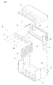
- FIG. 2 is a partial perspective view in which one end in the axial direction of the tube laminate shown in FIG. 1 is disassembled.
- FIG. 3 is a plan external view showing the entire EGR cooler of FIG. 4 is a side external view showing the entire EGR cooler of FIG. 1.
- FIG. 5 is a cross-sectional plan view showing the inside of FIG. 6 is a view taken along arrow VI-VI in FIG. 7 is a view taken along arrow VII-VII in FIG.
- FIG. 1 is a partial perspective view showing the inside of one end of an axial direction of a tube laminate in an EGR cooler which is a kind of the exhaust gas heat exchanger of the present invention
- FIG. 2 is an axis of the tube laminate shown in FIG. It is the fragmentary perspective view which decomposed
- the EGR cooler 1 includes an elongate case 2 having a substantially square cross section and an elongate tube stack 3 having a substantially square cross section housed in the case 2.
- the tube laminated body 3 is configured by laminating a plurality of flat tubes 4 in a multistage manner with a space between each other.
- the flat tubes 4 are stacked in multiple stages at predetermined intervals in the vertical direction of FIG.
- Hot exhaust gas A is supplied from the direction of the arrow in the axial direction of the case 2 and flows in the axial direction of the tube stack 3. Specifically, the exhaust gas A flows in from one end portion in the axial direction of the elongated tube stack 3, flows through the inside of each flat tube 4 in the axial direction, and flows out from the other end portion.
- the cooling water B introduced from the two cooling water introduction portions 5 and 6 is distributed in one end portion in the axial direction of the tube laminate 3, that is, the end portion on the side where the high-temperature exhaust gas A flows. It has come to be.
- the cooling water introduction part 5 is provided on the right side wall of the case 2 in FIG.
- cooling water introduction part 6 is provided on the left side wall of the case 2 in FIG.
- the introduction directions of the cooling water introduced from the cooling water introduction portions 5 and 6 are opposite to each other, and the introduction directions are parallel to the flat surface 4 a of the flat tube 4 in the tube laminate 3 and are the flat tube 4.
- the direction is perpendicular to the axial direction.
- cooling water is introduced horizontally from the cooling water introduction part 5 on the right side in the left direction of FIG. 1, and cooling water is introduced horizontally from the cooling water introduction part 6 on the left side in the right direction of FIG. Then, the cooling water distributed to one end portion in the axial direction of the elongated tube laminate 3 flows in the axial direction on the outer surface side of each flat tube 4 and flows out from the other end portion.
- the cooling water introduction parts 5 and 6 in the present embodiment are provided with baffle plates 7 each having a notch part 8.
- the two baffle plates 7 are formed in a plate shape, and a plurality of notches 8 (details of which will be described later) are formed therein.
- the cooling water introducing portions 5 and 6 are integrally connected by a connecting plate 9 so as to face each other on the plate surfaces, and the connecting plate 9 is provided with an opening 10 through which the exhaust gas A passes.
- the two baffle plates 7 integrally connected by the connecting plate 9 are integrally joined to the case 2 by brazing or the like. As shown in FIG.
- the baffle plate 7 has a receiving surface 11 that receives the cooling water introduced into the cooling water introducing portions 5 and 6, and a guide surface that guides the cooling water received by the receiving surface 11 to the notch portion 8. 12 is formed.
- the receiving surface 11 is formed as a surface perpendicular to the direction in which the cooling water is introduced, and the guide surface 12 is formed as a gentle inclined surface inclined in an obtuse direction from the receiving surface 11.
- a bent portion 13 is provided at the end of the receiving surface 11 opposite to the guide surface 12 so that a straight elongated tip edge is in close contact with the inner surface of the case 2. Is prevented from scattering and flowing out into the case 2.
- the folded portion 13 is formed by bending the end portion of the receiving surface 11.
- a bulging portion 14 bulging outward is formed in a portion overlapping the cooling water introducing portions 5 and 6 in the case 2 facing the baffle plate 7. Cooling water is introduced vertically and abuts perpendicularly to the surface of the receiving surface 11 formed on the baffle plate 7. The cooling water is smoothly guided from the receiving surface 11 along the guide surface 12 to the notch 8 and is distributed through the notch 8 to one end in the axial direction of the elongated tube stack 3.
- 1 and 2 show only one end portion of the EGR cooler in the axial direction of the tube laminate
- FIG. 3 shows a plan external view showing the entire EGR cooler of FIG. 4 shows an external view of the side. Further, FIG.
- FIG. 5 shows a plane cross section showing the inside of FIG. 3 to 5, an exhaust gas A supply portion 15 is provided at one end of the case 2 provided in the EGR cooler 1 in the axial direction, and the exhaust gas A circulated through the tube laminate 3 at the other end.
- the discharge part 16 is provided.
- Cooling water supply units 5 and 6 are provided in the vicinity of the exhaust gas A supply unit 15 in the left-right direction in FIGS. 3 and 5, and pass through the outer periphery of the tube stack 3 near the exhaust gas A discharge unit 16.
- a cooling water discharge portion 17 is provided. Since FIG. 5 shows the inside of the case 2, the case 2 is indicated by a one-dot chain line.
- FIG. 5 shows the surface of the flat surface 4 a of the flat tube 4 constituting the tube laminate 3.
- Elongated linear ribs 4b are formed in the vertical direction of FIG. 5 (corresponding to the horizontal direction of FIG. 1) at one end and the other end of each laminated flat tube 4. These ribs 4b have been conventionally used.
- the ribs 4b formed on the surface of the flat surface 4a at one end into which the exhaust gas A flows are cooled by the flow distributed at one end. Water is distributed on the surface of the flat surface 4a as shown by an arrow, and the local boiling is reduced by increasing the flow velocity of that portion.
- the protruding height of the rib 4b is set lower than the flow path height, and a part of the cooling water flows over the rib 4b.
- the state of distribution of the cooling water by the rib 4b is also indicated by arrows in FIG.
- FIG. 6 is a view taken along arrow VI-VI in FIG. 5
- FIG. 7 is a view taken along arrow VII-VII in FIG.
- the notch 8 of the baffle plate 7 shown in FIG. 6 has a notch 8 having a comb tooth shape and a relatively large opening area in the upper part of FIG. 6, and an oval-shaped notch having a small opening area below. 8 is formed.
- the notch portion 8 having a large opening area is mainly for distribution, and most of the cooling water is distributed to the tube laminate 3 through the small flow resistance.
- the notch 8 having a small opening area is mainly for applying a brazing material to the tube laminate 3 and has a high flow resistance, so that only a small amount of cooling water flows here.
- the baffle plate 7 in FIG. 6 is set such that more cooling water is distributed in the upper flat tube 4 group in FIG. 6 in the tube laminate 3 than in the lower flat tube 4 group. Will be above.
- the notch 8 of the baffle plate 7 shown in FIG. 7 has a comb-tooth-like notch 8 in the lower part of the figure and has a relatively large opening area. Part 8 is formed. That is, the baffle plate 7 in FIG. 7 is set so that more cooling water is distributed in the flat tube 4 group in the lower part of FIG. 7 than in the upper flat tube group 4 in the tube laminate 3. Below the layers.
- each cooling water distribution main body to be directed to different layers of the tube laminate, the coolant flows out from the notch portions 8 of the two baffle plates 7 as described above.
- the cooling water does not interfere with each other at the central portion of one end of the tube stack 3 in the axial direction, and as described above, it is possible to prevent the cooling water flow rate decrease phenomenon that may occur due to the interference, As a result, local boiling of the cooling water due to the decrease in flow velocity is prevented.
- the exhaust gas heat exchanger of the present invention is used as a cooler for an exhaust gas recirculation system or a heat exchanger for recovering heat of exhaust gas in a diesel engine or a gasoline engine.
Landscapes
- Engineering & Computer Science (AREA)
- Physics & Mathematics (AREA)
- Mechanical Engineering (AREA)
- General Engineering & Computer Science (AREA)
- Thermal Sciences (AREA)
- Geometry (AREA)
- Chemical & Material Sciences (AREA)
- Combustion & Propulsion (AREA)
- Exhaust-Gas Circulating Devices (AREA)
- Heat-Exchange Devices With Radiators And Conduit Assemblies (AREA)
- Details Of Heat-Exchange And Heat-Transfer (AREA)
Abstract
Description
一般的なEGRクーラは、ケース内部にチューブ積層体が配置され、排気ガスがチューブ積層体のチューブ軸方向における一方の端部から流入し各偏平チューブの内部を流通して他方の端部から流出し、ケースに設けられた冷却水導入部から導入される冷却水が前記一方の端部に供給されて各偏平チューブの外面側を流通するようになっている。
このように構成されるEGRクーラにおいて、チューブ積層体のチューブ軸方向における一方の端部から流入した排気ガスが、各チューブの内部を流通して他方の端部から流出する間に、チューブ外面側を排気ガスと同方向に流通する冷却水により冷却される。EGRクーラにおける排気ガスはチューブ積層体に流入する部分(上記チューブ積層体のチューブ軸方向における一方の端部)において最も高温であり、各チューブ内部を流通する間に冷却水との熱交換により次第にその温度が低下し、チューブ積層体から流出する部分(上記チューブ積層体のチューブ軸方向における他方の端部)において最も低温になる。
しかしながら通常、冷却水導入部はケースの一方の隅部に設けられ、その導入部から流入し各チューブ間の隙間を流れる冷却水は、流動抵抗の高い部分より低い部分に偏って流れる偏流が起り易く、各チューブの冷却水流入部分に均等に配流されない傾向がある。一般的にはケースの一方の隅部に設けた冷却水導入部からチューブ積層体の冷却水流入部分の各位置までの距離に長さの差があることが流動抵抗差の主たる要因になる。そしてチューブ積層体全体からみると、排気ガスの流入部に近いチューブ積層体の部分が高温化し、偏流により流量が減少した部分の冷却水において、特に局部沸騰が発生し易くなる。
このような冷却水の局部沸騰を抑制するため、チューブ積層体に対する冷却水配流を均一化させる効果を持つ冷却水供給チャンバの設置が提案されている。例えば特許文献1には、ケースの周壁の一端部に環状の冷却水供給チャンバを外嵌装着すると共に、その冷却水供給チャンバに入口管を接続し、さらに、前記冷却水供給チャンバ内のケース部分に該冷却水供給チャンバの内部と前記ケースの内部とを連通する環状スリット孔を向けた装置が開示されている。
また、特許文献2には上記特許文献1と別形態の冷却水供給チャンバを設置することが開示されている。特許文献2における冷却水供給チャンバは、その先端部が冷却水入口管に接続され、末端部がチューブ積層体を収容したケースに連通される。該冷却水供給チャンバは冷却水入口管側からケース側に向かって幅が次第に拡大され、その拡大端部はチューブ積層体を収容する部分のケース幅に一致している。それにより冷却水をケース幅全体に均一に供給できるようにしている。 Generally, an EGR (Exhaust Gas Recirculation) device is mounted on a vehicle in order to reduce nitrogen oxide (NOx) contained in exhaust gas discharged from an engine of a vehicle or the like, or to reduce pumping loss. Has been done. In many cases, this EGR device cools the exhaust gas, which is a kind of exhaust gas heat exchanger, in a system that recirculates a part of the exhaust gas to the intake side of the engine in order to lower the combustion temperature in the engine. An EGR cooler is provided.
A typical EGR cooler has a tube stack inside the case, and exhaust gas flows from one end in the tube axis direction of the tube stack, flows through each flat tube, and flows out from the other end. And the cooling water introduce | transduced from the cooling water introduction part provided in the case is supplied to said one edge part, and distribute | circulates the outer surface side of each flat tube.
In the EGR cooler configured as described above, while the exhaust gas flowing in from one end in the tube axial direction of the tube stack flows through the inside of each tube and flows out from the other end, the tube outer surface side Is cooled by cooling water flowing in the same direction as the exhaust gas. The exhaust gas in the EGR cooler is the highest temperature in the portion (one end portion in the tube axial direction of the tube laminate) flowing into the tube laminate, and gradually increases by heat exchange with the cooling water while flowing through each tube. The temperature decreases and becomes the lowest temperature at the portion flowing out from the tube laminate (the other end in the tube axis direction of the tube laminate).
However, normally, the cooling water introduction part is provided at one corner of the case, and the cooling water that flows from the introduction part and flows through the gaps between the tubes tends to drift to a lower part than a part having a high flow resistance. It tends to be easy and is not evenly distributed to the cooling water inflow portion of each tube. In general, the main cause of the difference in flow resistance is a difference in length in the distance from the cooling water introduction part provided at one corner of the case to each position of the cooling water inflow part of the tube laminate. When viewed from the entire tube stack, the portion of the tube stack near the inflow portion of the exhaust gas becomes high temperature, and local boiling particularly easily occurs in the cooling water in the portion where the flow rate is reduced due to drift.
In order to suppress such local boiling of the cooling water, it has been proposed to install a cooling water supply chamber having an effect of uniformizing the distribution of the cooling water with respect to the tube stack. For example, in
本発明の第2の発明は、第1の発明において、前記2つの冷却水導入部にはそれぞれ切欠き部を有するバッフルプレートが設けられ、導入される冷却水がそれら切欠き部を通って前記チューブ積層体のチューブ軸方向における一方の端部に配流されるように構成されていることを特徴とする(請求項2)。
本発明の第3の発明は、第2の発明において、前記2つのバッフルプレートは、それぞれの冷却水の配流主体がチューブ積層体の互いに異なる層間に向かうように構成されていることを特徴とする(請求項3)。
本発明の第4の発明は、第2または第3の発明において、前記2つのバッフルプレートは、排気ガスを流通させる開口部を有する連結板と一体構造であることを特徴とする(請求項4)。
本発明の第5の発明は、第4の発明において、前記2つのバッフルプレートの少なくとも一方には、冷却水導入部に導入される冷却水を受ける受け面と、受け面から冷却水を前記切欠き部へ導く誘導面を有することを特徴とする(請求項5)。
本発明の第6の発明は、第5の発明において、受け面における誘導面と反対側の端部に、折立部が設けられ、該折立部により受け面から冷却水が飛散してケース内部に流出することを防止するように構成されていることを特徴とする(請求項6)。 In order to solve the above problems, the present invention is configured as follows. That is, according to the first aspect of the present invention, a tube laminated body in which a plurality of flat tubes are laminated in multiple stages with a space between each other is disposed inside the case, and the exhaust gas is one side in the tube axial direction of the tube laminated body. The cooling water introduced from the cooling water introduction part provided in the case is supplied to the one end part, and flows into each flat tube. In the flat tube stack type exhaust gas heat exchanger configured to circulate on the outer surface side, two cooling water introduction portions are provided in the case, and the cooling water is introduced into the case from each cooling water introduction portion. The directions are opposite to each other, and the introduction directions are parallel to the flat surface of the flat tube in the tube laminate and perpendicular to the axial direction of the flat tube. Characterized in that (claim 1).
According to a second aspect of the present invention, in the first aspect, the two cooling water introduction portions are each provided with a baffle plate having a notch, and the introduced cooling water passes through the notches and is It is configured to be distributed to one end portion in the tube axial direction of the tube laminate (claim 2).
According to a third aspect of the present invention, in the second aspect, the two baffle plates are configured such that the main distribution bodies of the cooling water are directed to different layers of the tube laminate. (Claim 3).
According to a fourth aspect of the present invention, in the second or third aspect, the two baffle plates are integrated with a connecting plate having an opening through which exhaust gas flows. ).
According to a fifth aspect of the present invention, in the fourth aspect, at least one of the two baffle plates has a receiving surface for receiving the cooling water introduced into the cooling water introducing portion, and the cooling water is cut from the receiving surface. It has a guide surface that leads to the notch (claim 5).
According to a sixth aspect of the present invention, in the fifth aspect, a folded portion is provided at an end of the receiving surface opposite to the guide surface, and cooling water scatters from the receiving surface by the folded portion into the case. It is configured to prevent outflow (claim 6).
このように構成すると、チューブ積層体における偏平チューブの偏平面に平行な方向で且つ、排気ガスの流通方向と同軸なチューブ積層体の軸方向に垂直な両方向(左右方向)から冷却水が対向して導入されるので、冷却水がチューブ積層体の上記左右の一方に偏流することなく、チューブ積層体における前記一方の端部全体に亘って均一に配流(流量配分)される。その結果、冷却水の局部沸騰を効果的に抑制することができる。さらに、従来のようにケース外側に冷却水供給チャンバのシステムを設置する必要が無いので、排気ガス熱交換器の全体構成の複雑化、搭載容量の増大、コストアップなどの問題も生じない。
第2の発明は、前記2つの冷却水導入部にはそれぞれ切欠き部を有するバッフルプレートが設けられ、導入される冷却水がそれら切欠き部を通って前記チューブ積層体のチューブ軸方向における一方の端部に配流されるように構成されていることを特徴とする。
このように構成すると、バッフルプレートの切欠き部の形状や位置などを任意に設定することにより、排気ガス熱交換器の特性や構造に適合した最適な冷却水の配流設定ができる。その結果、切欠き部からチューブ積層体側への冷却水の流れに起こりがちな偏流をできるだけ抑制し、チューブ積層体における前記一方の端部に均一且つ充分な量の冷却水の供給ができる最適設定が可能になり、それによって局所的な沸騰現象も抑制される。
第3の発明は、前記2つのバッフルプレートにおける冷却水の配流主体(配分割合の多い部分)がチューブ積層体の互いに異なる層間に向かうように構成されていることを特徴とする。
このように構成すると、2つのバッフルプレートの切欠き部から互いに対向するように流出する冷却水は、前記チューブ積層体の軸方向の一方の端部の中央部で互いに干渉せず、干渉により発生する冷却水流速の低下現象を防止することができる。その結果、流速減少に起因する冷却水の局部沸騰も回避される。
本発明の第4の発明は、前記2つのバッフルプレートが連結板と一体構造であることを特徴とする。このように構成すると、排気ガス熱交換器の組立時に、バッフルプレートの位置決めおよび仮固定が不要になり、簡便かつ精度良く、バッフルプレートを設置することが可能になる。
本発明の第5の発明は、前記2つのバッフルプレートの少なくとも一方に、冷却水導入部に導入される冷却水を受ける受け面と、受け面から冷却水を前記切欠き部へ導く誘導面を有することを特徴とする。このように構成すると、冷却水導入部から導入された冷却水は、受け面で受け止められスムーズに誘導面を経て確実に切欠き部に導かれ、前記チューブ積層体の軸方向の一方の端部(排気ガス上流側)に配流される。
本発明の第6の発明は、前記受け面における誘導面と反対側の端部に折立部が設けられ、該折立部により受け面から冷却水が飛散してケース内部に流出することを防止するように構成されている。このように構成することにより、冷却水導入部から導入された冷却水の一部がバッフルプレートから切り欠き部を経ずにケース内に流出することが抑制され、流入した冷却水の全てが確実に切欠き部に導かれ、そこから前記チューブ積層体の軸方向の一方の端部に配流される。 In the first invention, the cooling water introduction part is provided in two places in the case, the introduction directions of the cooling water from the respective cooling water introduction parts to the inside of the case are opposed to each other, and the introduction directions are respectively The tube laminate is parallel to the flat surface of the flat tube and is perpendicular to the axial direction of the flat tube.
With this configuration, the cooling water faces in both directions (left and right) that are parallel to the flat surface of the flat tube in the tube stack and perpendicular to the axial direction of the tube stack that is coaxial with the flow direction of the exhaust gas. Therefore, the cooling water is evenly distributed (flow rate distribution) over the entire one end portion of the tube laminated body without drifting to the left and right sides of the tube laminated body. As a result, local boiling of the cooling water can be effectively suppressed. Further, since there is no need to install a cooling water supply chamber system outside the case as in the prior art, problems such as a complicated overall configuration of the exhaust gas heat exchanger, an increase in mounting capacity, and an increase in cost do not occur.
According to a second aspect of the present invention, baffle plates each having a notch are provided in each of the two cooling water introduction portions, and the introduced cooling water passes through the notches and is arranged in the tube axial direction of the tube laminate. It is comprised so that it may distribute to the edge part of this.
If comprised in this way, the optimal flow distribution setting of the cooling water suitable for the characteristic and structure of an exhaust-gas heat exchanger can be performed by setting arbitrarily the shape, position, etc. of the notch part of a baffle plate. As a result, it is possible to suppress the drift that tends to occur in the flow of the cooling water from the notch to the tube laminate side as much as possible, and to supply a uniform and sufficient amount of cooling water to the one end of the tube laminate. And local boiling phenomenon is also suppressed.
According to a third aspect of the present invention, the cooling water distribution main body (the portion with a large distribution ratio) in the two baffle plates is configured to be directed to different layers of the tube laminate.
With this configuration, the cooling water flowing out from the notches of the two baffle plates so as to face each other does not interfere with each other at the central portion of one end in the axial direction of the tube laminate, and is generated by the interference. It is possible to prevent the cooling water flow rate from decreasing. As a result, local boiling of the cooling water due to the decrease in flow velocity is also avoided.
A fourth invention of the present invention is characterized in that the two baffle plates are integrated with a connecting plate. If comprised in this way, at the time of an assembly of an exhaust gas heat exchanger, positioning and temporary fixation of a baffle plate will become unnecessary, and it will become possible to install a baffle plate simply and accurately.
According to a fifth aspect of the present invention, at least one of the two baffle plates includes a receiving surface that receives the cooling water introduced into the cooling water introduction portion, and a guide surface that guides the cooling water from the receiving surface to the notch portion. It is characterized by having. With this configuration, the cooling water introduced from the cooling water introduction portion is received by the receiving surface and smoothly guided to the cutout portion through the guiding surface, and one end portion in the axial direction of the tube laminated body. It is distributed to (exhaust gas upstream side).
According to a sixth aspect of the present invention, a folded portion is provided at an end of the receiving surface opposite to the guide surface, and the folded portion prevents cooling water from splashing from the receiving surface and flowing into the case. It is configured as follows. With this configuration, it is possible to prevent a part of the cooling water introduced from the cooling water introduction part from flowing into the case without passing through the notch from the baffle plate, and to ensure that all the cooling water that has flowed in. To the notch, and from there is distributed to one end of the tube laminate in the axial direction.
図2は図1に示すチューブ積層体の軸方向の一方の端部を分解した部分斜視図。
図3は図1のEGRクーラの全体を示す平面外観図。
図4は図1のEGRクーラの全体を示す側面外観図
図5は図3の内部を示す平断面図。
図6は図5のVI−VI矢視図。
図7は図5のVII−VII矢視図。 FIG. 1 is a partial perspective view showing the inside of one end portion in the axial direction of a tube laminate in an EGR cooler which is a kind of an exhaust gas heat exchanger of the present invention.
FIG. 2 is a partial perspective view in which one end in the axial direction of the tube laminate shown in FIG. 1 is disassembled.
FIG. 3 is a plan external view showing the entire EGR cooler of FIG.
4 is a side external view showing the entire EGR cooler of FIG. 1. FIG. 5 is a cross-sectional plan view showing the inside of FIG.
6 is a view taken along arrow VI-VI in FIG.
7 is a view taken along arrow VII-VII in FIG.
チューブ積層体3は複数の偏平チューブ4を互いに間隔を有して多段に積層し構成される。各偏平チューブ4は図1の上下方向に互いに所定の間隔をもって多段に積層され、各偏平チューブ4の上下面はそれぞれ偏平面4aとなっている。
高温の排気ガスAは矢印方向からケース2の軸方向に供給されてチューブ積層体3の軸方向に流入する。具体的には、排気ガスAは細長いチューブ積層体3の軸方向における一方の端部から流入し、各偏平チューブ4の内部を軸方向に流通して他方の端部から流出する。チューブ積層体3の軸方向における一方の端部、すなわち高温の排気ガスAが流入する側の端部におけるケース2には、2つの冷却水導入部5、6から導入される冷却水Bが配流されるようになっている。
冷却水導入部5はケース2の図1における右側側壁に設けられ、冷却水導入部6はケース2の図1における左側側壁に設けられる。冷却水導入部5,6から導入される冷却水の導入方向は、互いに対向する方向で、さらに該導入方向はそれぞれ前記チューブ積層体3における偏平チューブ4の偏平面4aに平行で且つ偏平チューブ4の軸方向に垂直な方向となっている。図1では、右側の冷却水導入部5から図1の左方向に水平に冷却水が導入され、左側の冷却水導入部6から図1の右方向に水平に冷却水が導入される。そして細長いチューブ積層体3の軸方向における一方の端部に配流された冷却水は、各偏平チューブ4の外面側を軸方向に流通し、他方の端部から流出する。
本実施形態における冷却水導入部5,6は、それぞれ切欠き部8を有するバッフルプレート7が設けられる。図2に示すように、2つのバッフルプレート7は板状に形成され、その内部に複数の切欠き部8(その詳細な作用は後述する)が形成されている。そして冷却水導入部5,6はその板面で互いに対向するように、連結板9で一体的に連結されおり、連結板9には排気ガスAを通過させる開口部10が設けられている。なお、連結板9で一体的に連結された2つバッフルプレート7はろう付等により、ケース2と一体に接合される。
図2に示すように、バッフルプレート7には冷却水導入部5,6に導入される冷却水を受ける受け面11と、受け面11で受けた冷却水を前記切欠き部8へ導く誘導面12が形成されている。受け面11は冷却水の導入方向に対して垂直な面で形成され、誘導面12は受け面11から鈍角な方向に傾斜する緩やかな傾斜面で形成されている。さらに受け面11における誘導面12と反対側の端部には、直線状の細長い先端縁が前記ケース2の内面に密着する折立部13が設けられ、該折立部13により受け面11から冷却水が飛散してケース2内部に流出することを防止している。なお折立部13は受け面11の端部を折り曲げることにより形成される。
一方、図2に示すように、バッフルプレート7に対向するケース2において冷却水導入部5,6と重なる部分には、外側へ膨出する膨出部14が形成され、この膨出部14に冷却水が垂直に導入され、前記バッフルプレート7に形成された受け面11の面に垂直に突き当たる。冷却水は受け面11から誘導面12に沿ってスムーズに切欠き部8に導かれ、切欠き部8を通して前記細長いチューブ積層体3の軸方向における一方の端部に配流される。
図1、図2には、EGRクーラにおけるチューブ積層体の軸方向の一方の端部だけが示されているが、図3に図1のEGRクーラの全体を示す平面外観図が示され、図4にその側面外観図が示されている。更に図5に図3の内部を示す平断面が示されている。
図3~図5において、EGRクーラ1に設けたケース2の軸方向の一方の端部に排気ガスAの供給部15が設けられ、他方の端部にチューブ積層体3を流通した排気ガスAの排出部16が設けられる。排気ガスAの供給部15の近くに冷却水供給部5,6が図3,5の左右方向に対向して設けられ、排気ガスAの排出部16の近くにチューブ積層体3の外周を通過した冷却水の排出部17が設けられている。
図5はケース2の内部を示すため、ケース2が一点鎖線で示されている。図5にはチューブ積層体3を構成する偏平チューブ4の偏平面4aの表面が示されている。積層された各偏平チューブ4の一方の端部および他方の端部にそれぞれ細長い直線状のリブ4bが図5の上下方向(図1の左右方向に相当)に形成されている。これらのリブ4bは従来から採用されているものであるが、特に排気ガスAが流入する一方の端部の偏平面4aの表面に形成されたリブ4bは、一方の先端部に配流された冷却水を矢印のように偏平面4aの表面に配流し、その部分の流速を高めて局部沸騰を低減化している。なお、リブ4bの突出高さは流路高さより低く設定されており、冷却水の一部はリブ4bを乗り越えて流れる。リブ4bによる冷却水の配流の様子は図1にも矢印で示されている。
図6は図5のVI−VI矢視図で、図7は図5のVII−VII矢視図である。図6に示すバッフルプレート7の切欠き部8は図6の上方にくしの歯状で比較的開口面積の大きい切欠き部8が形成され、下方に長円型で開口面積の小さい切欠き部8が形成されている。開口面積の大きい切欠き部8は主に配流のためのものであり、大部分の冷却水は流動抵抗の少ないここを通ってチューブ積層体3に配流される。一方、開口面積の小さい切欠き部8は主にチューブ積層体3にろう材を塗布するためのものであり、流動抵抗が大きいので、ここには微量の冷却水しか流れない。すなわち図6のバッフルプレート7はチューブ積層体3における図6上方の偏平チューブ4群が下方の偏平チューブ4群より多くの冷却水が配流されるように設定されるので、その配流主体はチューブ層間の上方になる。
また、図7に示すバッフルプレート7の切欠き部8は図中下方にくしの歯状で比較的開口面積の大きい切欠き部8が形成され、上方に長円型で開口面積の小さい切欠き部8が形成されている。すなわち図7のバッフルプレート7はチューブ積層体3における図7下方の偏平チューブ4群が上方の偏平チューブ4群より多くの冷却水が配流されるように設定されているので、その配流主体はチューブ層間の下方になる。
このように、それぞれの冷却水の配流主体がチューブ積層体の互いに異なる層間に向かうように構成することにより、前記のように2つのバッフルプレート7の切欠き部8から互いに対向するように流出する冷却水がチューブ積層体3の軸方向の一方の端部の中央部で互いに干渉せず、前記のように、干渉により発生する可能性がある冷却水の流速低下現象を予防することができ、結果として流速減少に起因する冷却水の局部的沸騰が防止される。 FIG. 1 is a partial perspective view showing the inside of one end of an axial direction of a tube laminate in an EGR cooler which is a kind of the exhaust gas heat exchanger of the present invention, and FIG. 2 is an axis of the tube laminate shown in FIG. It is the fragmentary perspective view which decomposed | disassembled one edge part of a direction. In these drawings, the
The tube laminated
Hot exhaust gas A is supplied from the direction of the arrow in the axial direction of the
The cooling
The cooling
As shown in FIG. 2, the
On the other hand, as shown in FIG. 2, a bulging
1 and 2 show only one end portion of the EGR cooler in the axial direction of the tube laminate, FIG. 3 shows a plan external view showing the entire EGR cooler of FIG. 4 shows an external view of the side. Further, FIG. 5 shows a plane cross section showing the inside of FIG.
3 to 5, an exhaust gas
Since FIG. 5 shows the inside of the
6 is a view taken along arrow VI-VI in FIG. 5, and FIG. 7 is a view taken along arrow VII-VII in FIG. The
Further, the
In this way, by configuring each cooling water distribution main body to be directed to different layers of the tube laminate, the coolant flows out from the
2 ケース
3 チューブ積層体
4 偏平チューブ
4a 偏平面
4b リブ
5,6 冷却水導入部
7 バッフルプレート
8 切欠き部
9 連結板
10 開口部
11 受け面
12 誘導面
13 折立部
14 膨出部
15 供給部
16,17 排出部
A 排気ガス
B 冷却水 DESCRIPTION OF
Claims (6)
- 複数の偏平チューブ(4)を互いに間隔を有して多段に積層し構成したチューブ積層体(3)がケース(2)内部に配置され、排気ガスがチューブ積層体(3)のチューブ軸方向における一方の端部から流入し各偏平チューブ(4)の内部を流通して他方の端部から流出し、ケース(2)に設けた冷却水導入部から導入される冷却水が前記一方の端部に供給されて各偏平チューブ(4)の外面側を流通するように構成した偏平チューブ積層型の排気ガス熱交換器において、
ケース(2)には前記冷却水導入部(5),(6)が2箇所設けられ、各冷却水導入部(5),(6)からケース(2)内部への冷却水の導入方向は互いに対向する方向となっており、さらに該導入方向はそれぞれ前記チューブ積層体(3)における偏平チューブ(4)の偏平面(4a)に平行で且つ偏平チューブ(4)の軸方向に垂直な方向となっていることを特徴とする偏平チューブ積層型の排気ガス熱交換器。 A tube laminate (3) configured by laminating a plurality of flat tubes (4) in multiple stages at intervals is disposed inside the case (2), and exhaust gas is disposed in the tube axial direction of the tube laminate (3). Cooling water introduced from a cooling water inlet provided in the case (2) flows in from the one end, flows through the inside of each flat tube (4), flows out from the other end, and the one end A flat tube stack type exhaust gas heat exchanger configured to flow through the outer surface side of each flat tube (4),
The cooling water introduction part (5), (6) is provided at two places in the case (2), and the introduction direction of the cooling water from each cooling water introduction part (5), (6) to the inside of the case (2) is The introduction directions are directions parallel to the flat surface (4a) of the flat tube (4) and perpendicular to the axial direction of the flat tube (4) in the tube laminate (3). A flat tube stack type exhaust gas heat exchanger characterized by the above. - 前記2つの冷却水導入部(5),(6)にはそれぞれ切欠き部(8)を有するバッフルプレート(7)が設けられ、導入される冷却水がそれら切欠き部(8)を通って前記チューブ積層体(3)のチューブ軸方向における一方の端部に配流されるように構成されていることを特徴とする請求項1に記載の偏平チューブ積層型の排気ガス熱交換器。 The two cooling water introduction portions (5) and (6) are each provided with a baffle plate (7) having a notch (8), and the introduced cooling water passes through the notch (8). 2. The flat tube stack type exhaust gas heat exchanger according to claim 1, wherein the exhaust gas heat exchanger is configured to be distributed to one end portion in the tube axis direction of the tube stack (3).
- 前記2つのバッフルプレート(7)は、それぞれの冷却水の配流主体がチューブ積層体(3)の互いに異なる層間に向かうように構成されていることを特徴とする請求項2に記載の偏平チューブ積層型の排気ガス熱交換器。 The flat tube stack according to claim 2, wherein the two baffle plates (7) are configured such that the main distribution bodies of the respective cooling waters are directed to different layers of the tube stack (3). Type exhaust gas heat exchanger.
- 前記2つのバッフルプレート(7)は、排気ガスを流通させる開口部(10)を有する連結板(9)と一体構造であることを特徴とする請求項2または請求項3に記載の偏平チューブ積層型の排気ガス熱交換器。 The flat tube laminate according to claim 2 or 3, wherein the two baffle plates (7) are integrally formed with a connecting plate (9) having an opening (10) through which exhaust gas flows. Type exhaust gas heat exchanger.
- 前記2つのバッフルプレート(7)の少なくとも一方には、冷却水導入部(5),(6)に導入される冷却水を受ける受け面(11)と、受け面(11)から冷却水を前記切欠き部(8)へ導く誘導面(12)を有することを特徴とする請求項4に記載の偏平チューブ積層型の排気ガス熱交換器。 At least one of the two baffle plates (7) receives the cooling water introduced into the cooling water introduction portions (5) and (6), and receives the cooling water from the receiving surface (11). 5. The flat tube laminated exhaust gas heat exchanger according to claim 4, further comprising a guide surface (12) leading to the notch (8).
- 受け面(11)における誘導面(12)と反対側の端部には、折立部(13)が設けられ、該折立部(13)により受け面(11)から冷却水が飛散してケース(2)内部に流出することを防止するように構成されていることを特徴とする請求項5に記載の偏平チューブ積層型の排気ガス熱交換器。 A folded portion (13) is provided at the end of the receiving surface (11) opposite to the guide surface (12), and cooling water is scattered from the receiving surface (11) by the folded portion (13). 2) The flat tube stack type exhaust gas heat exchanger according to claim 5, wherein the exhaust gas heat exchanger is configured to prevent outflow to the inside.
Priority Applications (3)
| Application Number | Priority Date | Filing Date | Title |
|---|---|---|---|
| EP17738584.6A EP3404247B1 (en) | 2016-01-12 | 2017-01-11 | Exhaust gas heat exchanger having stacked flat tubes |
| US16/068,716 US10563624B2 (en) | 2016-01-12 | 2017-01-11 | Exhaust gas heat exchanger having stacked flat tubes |
| JP2017561213A JP6766076B2 (en) | 2016-01-12 | 2017-01-11 | Flat tube laminated exhaust gas heat exchanger |
Applications Claiming Priority (2)
| Application Number | Priority Date | Filing Date | Title |
|---|---|---|---|
| JP2016003809 | 2016-01-12 | ||
| JP2016-003809 | 2016-01-12 |
Publications (1)
| Publication Number | Publication Date |
|---|---|
| WO2017122832A1 true WO2017122832A1 (en) | 2017-07-20 |
Family
ID=59311192
Family Applications (1)
| Application Number | Title | Priority Date | Filing Date |
|---|---|---|---|
| PCT/JP2017/001618 WO2017122832A1 (en) | 2016-01-12 | 2017-01-11 | Exhaust gas heat exchanger having stacked flat tubes |
Country Status (4)
| Country | Link |
|---|---|
| US (1) | US10563624B2 (en) |
| EP (1) | EP3404247B1 (en) |
| JP (1) | JP6766076B2 (en) |
| WO (1) | WO2017122832A1 (en) |
Cited By (3)
| Publication number | Priority date | Publication date | Assignee | Title |
|---|---|---|---|---|
| EP3567331A1 (en) * | 2018-05-09 | 2019-11-13 | João de Deus & Filhos, S.A. | Heat exchanger |
| WO2020003949A1 (en) * | 2018-06-29 | 2020-01-02 | カルソニックカンセイ株式会社 | Heat exchanger |
| EP3734211A4 (en) * | 2017-12-27 | 2021-09-22 | T.Rad Co., Ltd. | Header plateless type heat exchanger |
Families Citing this family (5)
| Publication number | Priority date | Publication date | Assignee | Title |
|---|---|---|---|---|
| EP3454001B1 (en) * | 2017-09-06 | 2020-05-06 | Borgwarner Emissions Systems Spain, S.L.U. | Compact heat exchanger |
| KR20200006779A (en) * | 2018-07-11 | 2020-01-21 | 현대자동차주식회사 | Exhaust gas recirculation cooler |
| EP3926281B1 (en) * | 2020-06-17 | 2023-03-22 | Valeo Autosystemy Sp. z o.o. | A water charge air-cooler |
| EP4015976A1 (en) * | 2020-12-15 | 2022-06-22 | Valeo Autosystemy SP. Z.O.O. | Heat exchanger |
| FR3120398B1 (en) * | 2021-03-08 | 2023-03-31 | Renault Sas | Trapezoidal section tube exchanger device |
Citations (5)
| Publication number | Priority date | Publication date | Assignee | Title |
|---|---|---|---|---|
| JP2003090693A (en) * | 2001-07-10 | 2003-03-28 | Denso Corp | Exhaust gas heat exchanger |
| WO2009046956A1 (en) * | 2007-10-13 | 2009-04-16 | Modine Manufacturing Company | Heat exchanger, particularly exhaust gas heat exchanger |
| JP4386215B2 (en) * | 1999-02-15 | 2009-12-16 | 臼井国際産業株式会社 | EGR gas cooling device |
| JP2013053620A (en) * | 2011-08-10 | 2013-03-21 | Usui Kokusai Sangyo Kaisha Ltd | Multi-tube type heat exchanger |
| JP2014194296A (en) * | 2013-03-28 | 2014-10-09 | Usui Kokusai Sangyo Kaisha Ltd | Multi-tube heat exchanger |
Family Cites Families (5)
| Publication number | Priority date | Publication date | Assignee | Title |
|---|---|---|---|---|
| US7077190B2 (en) | 2001-07-10 | 2006-07-18 | Denso Corporation | Exhaust gas heat exchanger |
| JP2005069064A (en) | 2003-08-21 | 2005-03-17 | Hino Motors Ltd | Egr cooler |
| JP4634291B2 (en) | 2005-12-01 | 2011-02-16 | 株式会社ティラド | EGR cooler |
| JP2010048536A (en) * | 2008-08-25 | 2010-03-04 | Denso Corp | Heat exchanger |
| JP2010090785A (en) | 2008-10-07 | 2010-04-22 | Denso Corp | Exhaust gas cooling system |
-
2017
- 2017-01-11 US US16/068,716 patent/US10563624B2/en active Active
- 2017-01-11 WO PCT/JP2017/001618 patent/WO2017122832A1/en active Application Filing
- 2017-01-11 JP JP2017561213A patent/JP6766076B2/en active Active
- 2017-01-11 EP EP17738584.6A patent/EP3404247B1/en active Active
Patent Citations (5)
| Publication number | Priority date | Publication date | Assignee | Title |
|---|---|---|---|---|
| JP4386215B2 (en) * | 1999-02-15 | 2009-12-16 | 臼井国際産業株式会社 | EGR gas cooling device |
| JP2003090693A (en) * | 2001-07-10 | 2003-03-28 | Denso Corp | Exhaust gas heat exchanger |
| WO2009046956A1 (en) * | 2007-10-13 | 2009-04-16 | Modine Manufacturing Company | Heat exchanger, particularly exhaust gas heat exchanger |
| JP2013053620A (en) * | 2011-08-10 | 2013-03-21 | Usui Kokusai Sangyo Kaisha Ltd | Multi-tube type heat exchanger |
| JP2014194296A (en) * | 2013-03-28 | 2014-10-09 | Usui Kokusai Sangyo Kaisha Ltd | Multi-tube heat exchanger |
Cited By (5)
| Publication number | Priority date | Publication date | Assignee | Title |
|---|---|---|---|---|
| EP3734211A4 (en) * | 2017-12-27 | 2021-09-22 | T.Rad Co., Ltd. | Header plateless type heat exchanger |
| EP3567331A1 (en) * | 2018-05-09 | 2019-11-13 | João de Deus & Filhos, S.A. | Heat exchanger |
| US10989487B2 (en) | 2018-05-09 | 2021-04-27 | João de Deus & Filhos, S.A. | Heat exchanger |
| WO2020003949A1 (en) * | 2018-06-29 | 2020-01-02 | カルソニックカンセイ株式会社 | Heat exchanger |
| CN112219083A (en) * | 2018-06-29 | 2021-01-12 | 马瑞利株式会社 | Heat exchanger |
Also Published As
| Publication number | Publication date |
|---|---|
| US10563624B2 (en) | 2020-02-18 |
| JPWO2017122832A1 (en) | 2018-11-01 |
| EP3404247A1 (en) | 2018-11-21 |
| JP6766076B2 (en) | 2020-10-07 |
| EP3404247A4 (en) | 2019-09-04 |
| EP3404247B1 (en) | 2020-09-09 |
| US20190017471A1 (en) | 2019-01-17 |
Similar Documents
| Publication | Publication Date | Title |
|---|---|---|
| WO2017122832A1 (en) | Exhaust gas heat exchanger having stacked flat tubes | |
| KR101925201B1 (en) | Heat exchange device | |
| US6595274B2 (en) | Exhaust gas heat exchanger | |
| US8844504B2 (en) | Heat exchanger and method of manufacturing the same | |
| US9664450B2 (en) | Fin support structures for charge air coolers | |
| JP6303755B2 (en) | Exhaust heat exchanger | |
| JP2009127937A (en) | Heat exchanger | |
| KR101793752B1 (en) | Heat exchanger for gases, in particular for the exhaust gases of an engine | |
| US20140246185A1 (en) | Heat Exchanger With Stacked Plates | |
| US20130092360A1 (en) | Heat exchanger and sheet for the exchanger | |
| KR20140118878A (en) | Air to air heat exchanger | |
| JP2010223508A (en) | Intercooler of engine for vehicle | |
| JP2003090693A (en) | Exhaust gas heat exchanger | |
| KR101694083B1 (en) | Gas heat exchanger, in particular for exhaust gases of an engine | |
| JP6577282B2 (en) | Heat exchanger | |
| KR20140088124A (en) | Heat exchanger for gases, especially engine exhaust gases | |
| KR102173402B1 (en) | EGR cooler for vehicle | |
| KR102184022B1 (en) | Heat exchanger for exhaust gas cooling in motor vehicles | |
| JP6944432B2 (en) | Heat exchanger | |
| CN110608113B (en) | Exhaust gas recirculation cooling device for vehicle engine | |
| CN109154478B (en) | Heat exchanger for gases, in particular for engine exhaust gases | |
| US20190360757A1 (en) | Heat exchanger | |
| US20230392869A1 (en) | 221-0240 heat exchanger for a vehicle | |
| JP7136757B2 (en) | Heat exchanger | |
| JP2018131908A (en) | EGR cooler |
Legal Events
| Date | Code | Title | Description |
|---|---|---|---|
| 121 | Ep: the epo has been informed by wipo that ep was designated in this application |
Ref document number: 17738584 Country of ref document: EP Kind code of ref document: A1 |
|
| ENP | Entry into the national phase |
Ref document number: 2017561213 Country of ref document: JP Kind code of ref document: A |
|
| NENP | Non-entry into the national phase |
Ref country code: DE |
|
| WWE | Wipo information: entry into national phase |
Ref document number: 2017738584 Country of ref document: EP |
|
| ENP | Entry into the national phase |
Ref document number: 2017738584 Country of ref document: EP Effective date: 20180813 |