WO2017122379A1 - 生体信号計測装置 - Google Patents
生体信号計測装置 Download PDFInfo
- Publication number
- WO2017122379A1 WO2017122379A1 PCT/JP2016/073112 JP2016073112W WO2017122379A1 WO 2017122379 A1 WO2017122379 A1 WO 2017122379A1 JP 2016073112 W JP2016073112 W JP 2016073112W WO 2017122379 A1 WO2017122379 A1 WO 2017122379A1
- Authority
- WO
- WIPO (PCT)
- Prior art keywords
- biological signal
- electrodes
- sheet
- measuring device
- circuit
- Prior art date
- Legal status (The legal status is an assumption and is not a legal conclusion. Google has not performed a legal analysis and makes no representation as to the accuracy of the status listed.)
- Ceased
Links
Images



Classifications
-
- A—HUMAN NECESSITIES
- A61—MEDICAL OR VETERINARY SCIENCE; HYGIENE
- A61B—DIAGNOSIS; SURGERY; IDENTIFICATION
- A61B5/00—Measuring for diagnostic purposes; Identification of persons
- A61B5/68—Arrangements of detecting, measuring or recording means, e.g. sensors, in relation to patient
- A61B5/6801—Arrangements of detecting, measuring or recording means, e.g. sensors, in relation to patient specially adapted to be attached to or worn on the body surface
- A61B5/683—Means for maintaining contact with the body
- A61B5/6832—Means for maintaining contact with the body using adhesives
- A61B5/6833—Adhesive patches
-
- A—HUMAN NECESSITIES
- A61—MEDICAL OR VETERINARY SCIENCE; HYGIENE
- A61B—DIAGNOSIS; SURGERY; IDENTIFICATION
- A61B5/00—Measuring for diagnostic purposes; Identification of persons
- A61B5/0002—Remote monitoring of patients using telemetry, e.g. transmission of vital signals via a communication network
-
- A—HUMAN NECESSITIES
- A61—MEDICAL OR VETERINARY SCIENCE; HYGIENE
- A61B—DIAGNOSIS; SURGERY; IDENTIFICATION
- A61B5/00—Measuring for diagnostic purposes; Identification of persons
- A61B5/24—Detecting, measuring or recording bioelectric or biomagnetic signals of the body or parts thereof
- A61B5/25—Bioelectric electrodes therefor
- A61B5/251—Means for maintaining electrode contact with the body
- A61B5/257—Means for maintaining electrode contact with the body using adhesive means, e.g. adhesive pads or tapes
-
- A—HUMAN NECESSITIES
- A61—MEDICAL OR VETERINARY SCIENCE; HYGIENE
- A61B—DIAGNOSIS; SURGERY; IDENTIFICATION
- A61B5/00—Measuring for diagnostic purposes; Identification of persons
- A61B5/24—Detecting, measuring or recording bioelectric or biomagnetic signals of the body or parts thereof
- A61B5/25—Bioelectric electrodes therefor
- A61B5/279—Bioelectric electrodes therefor specially adapted for particular uses
- A61B5/291—Bioelectric electrodes therefor specially adapted for particular uses for electroencephalography [EEG]
-
- A—HUMAN NECESSITIES
- A61—MEDICAL OR VETERINARY SCIENCE; HYGIENE
- A61B—DIAGNOSIS; SURGERY; IDENTIFICATION
- A61B5/00—Measuring for diagnostic purposes; Identification of persons
- A61B5/24—Detecting, measuring or recording bioelectric or biomagnetic signals of the body or parts thereof
- A61B5/25—Bioelectric electrodes therefor
- A61B5/279—Bioelectric electrodes therefor specially adapted for particular uses
- A61B5/296—Bioelectric electrodes therefor specially adapted for particular uses for electromyography [EMG]
-
- A—HUMAN NECESSITIES
- A61—MEDICAL OR VETERINARY SCIENCE; HYGIENE
- A61B—DIAGNOSIS; SURGERY; IDENTIFICATION
- A61B5/00—Measuring for diagnostic purposes; Identification of persons
- A61B5/24—Detecting, measuring or recording bioelectric or biomagnetic signals of the body or parts thereof
- A61B5/316—Modalities, i.e. specific diagnostic methods
- A61B5/369—Electroencephalography [EEG]
-
- A—HUMAN NECESSITIES
- A61—MEDICAL OR VETERINARY SCIENCE; HYGIENE
- A61B—DIAGNOSIS; SURGERY; IDENTIFICATION
- A61B5/00—Measuring for diagnostic purposes; Identification of persons
- A61B5/68—Arrangements of detecting, measuring or recording means, e.g. sensors, in relation to patient
- A61B5/6801—Arrangements of detecting, measuring or recording means, e.g. sensors, in relation to patient specially adapted to be attached to or worn on the body surface
- A61B5/6843—Monitoring or controlling sensor contact pressure
-
- A—HUMAN NECESSITIES
- A61—MEDICAL OR VETERINARY SCIENCE; HYGIENE
- A61B—DIAGNOSIS; SURGERY; IDENTIFICATION
- A61B2503/00—Evaluating a particular growth phase or type of persons or animals
- A61B2503/04—Babies, e.g. for SIDS detection
-
- A—HUMAN NECESSITIES
- A61—MEDICAL OR VETERINARY SCIENCE; HYGIENE
- A61B—DIAGNOSIS; SURGERY; IDENTIFICATION
- A61B2560/00—Constructional details of operational features of apparatus; Accessories for medical measuring apparatus
- A61B2560/02—Operational features
- A61B2560/0204—Operational features of power management
- A61B2560/0214—Operational features of power management of power generation or supply
-
- A—HUMAN NECESSITIES
- A61—MEDICAL OR VETERINARY SCIENCE; HYGIENE
- A61B—DIAGNOSIS; SURGERY; IDENTIFICATION
- A61B2562/00—Details of sensors; Constructional details of sensor housings or probes; Accessories for sensors
- A61B2562/02—Details of sensors specially adapted for in-vivo measurements
- A61B2562/0209—Special features of electrodes classified in A61B5/24, A61B5/25, A61B5/283, A61B5/291, A61B5/296, A61B5/053
-
- A—HUMAN NECESSITIES
- A61—MEDICAL OR VETERINARY SCIENCE; HYGIENE
- A61B—DIAGNOSIS; SURGERY; IDENTIFICATION
- A61B2562/00—Details of sensors; Constructional details of sensor housings or probes; Accessories for sensors
- A61B2562/04—Arrangements of multiple sensors of the same type
- A61B2562/046—Arrangements of multiple sensors of the same type in a matrix array
-
- A—HUMAN NECESSITIES
- A61—MEDICAL OR VETERINARY SCIENCE; HYGIENE
- A61B—DIAGNOSIS; SURGERY; IDENTIFICATION
- A61B2562/00—Details of sensors; Constructional details of sensor housings or probes; Accessories for sensors
- A61B2562/12—Manufacturing methods specially adapted for producing sensors for in-vivo measurements
- A61B2562/125—Manufacturing methods specially adapted for producing sensors for in-vivo measurements characterised by the manufacture of electrodes
-
- A—HUMAN NECESSITIES
- A61—MEDICAL OR VETERINARY SCIENCE; HYGIENE
- A61B—DIAGNOSIS; SURGERY; IDENTIFICATION
- A61B2562/00—Details of sensors; Constructional details of sensor housings or probes; Accessories for sensors
- A61B2562/16—Details of sensor housings or probes; Details of structural supports for sensors
- A61B2562/164—Details of sensor housings or probes; Details of structural supports for sensors the sensor is mounted in or on a conformable substrate or carrier
-
- A—HUMAN NECESSITIES
- A61—MEDICAL OR VETERINARY SCIENCE; HYGIENE
- A61B—DIAGNOSIS; SURGERY; IDENTIFICATION
- A61B2562/00—Details of sensors; Constructional details of sensor housings or probes; Accessories for sensors
- A61B2562/16—Details of sensor housings or probes; Details of structural supports for sensors
- A61B2562/166—Details of sensor housings or probes; Details of structural supports for sensors the sensor is mounted on a specially adapted printed circuit board
Definitions
- the present invention relates to an apparatus for measuring changes in electric potential over time, such as in-vivo electrical activity, with an electrode.
- Changes in potentials that occur with in vivo activities can be measured via electrodes attached to the outside of the living body.
- the change in potential measured in this way is conventionally used as a biological signal for non-invasively grasping the presence or absence and degree of abnormality in a living body in a hospital, a research institution, or the like.
- Devices for this measurement that is, medical and research inspection devices such as electroencephalographs and electrocardiographs, have been miniaturized in the same manner as consumer devices.
- medical and research inspection devices such as electroencephalographs and electrocardiographs
- examination equipment is required to have high accuracy, and is often used for subjects who have little activity in a medical facility examination room, examination room, home visit, and the like.
- the size and weight of the electroencephalograph is portable enough to be stored in a caster-equipped table or a dedicated case when not in use. It is a grade (refer nonpatent literature 1).
- an electrocardiograph has a portable size, and is composed of a main body made of a hard casing and a plurality of cables having electrodes at the tips that extend from the main body or are connected to the main body.
- the inspection by the conventional inspection equipment is performed in a specific place as described above for a relatively short time, the physical burden on the subject is not so great. However, depending on the purpose of the examination and the subject, the burden may be inappropriately large.
- a test for acquiring a biological signal during sleep can be considered. Electrodes to be worn multiple times, the coating agent to the place where the electrodes are worn, the contact of the cable connecting the electrode and the body to the skin, etc., gives the subject a strong feeling of wearing or discomfort, and makes the subject fall asleep Or affect the electrical activity that occurs in the subject's body. As a result, the biological signal of the normal sleep state of the subject cannot be acquired. In particular, in the case of subjects with low stress resistance such as infants and toddlers, and subjects with insufficient physical control ability, it is difficult to perform a test because it shows a large body reaction to this feeling of wearing or discomfort. Sometimes.
- EEG measurement is basically difficult for patients and their families to perform at home like simple examinations with stethoscopes, blood pressure monitors, thermometers, etc., and needs to be performed at medical institutions.
- Portable electrocardiographs can be used at home, but have limitations in terms of performance such as the number of channels. Therefore, measurement of biological signals may need to be performed in a medical institution even in a severe situation, and not only the physical burden on the patient (subject) but also the subject. For both medical institutions and medical institutions, the time burden and the financial burden are large.
- the present invention has been made in view of these problems, and an object of the present invention is to provide a biological signal measuring device that can achieve both the simplicity of measurement and high performance while suppressing the wearing feeling and the uncomfortable feeling given to the subject.
- a biological signal measuring device provided to achieve the above object is a biological signal measuring device used by being attached to a living body, and is connected to a plurality of electrodes and each of the plurality of electrodes. Signal processing for wirelessly transmitting a biological signal obtained through the plurality of wires connected to the plurality of wires, and a sheet having a plurality of wires formed, stretchable and bendable, and having adhesiveness And a substrate on which a circuit is mounted. The plurality of electrodes are exposed on a surface of the sheet, and the sheet and the substrate are overlapped so that a back surface of the sheet and the substrate face each other.
- the plurality of electrodes provided in this biological signal measuring device are attached to a living body together with a stickable sheet such as a compress. Therefore, no coating agent is required and there is no cable that contacts the skin. Further, since the pasted sheet and electrode follow the shape and movement of the pasted biological part, they are unlikely to deviate or peel off from the pasting position.
- the entire biological signal measuring device is compactly constructed with a configuration in which the substrate and the sheet are stacked, and there is no cable that restricts the movement of the subject, so that the subject feels wearing and uncomfortable. It is hard to let you.
- such a biological signal measuring apparatus has a size in which an outer shape of the sheet and the substrate when viewed from above in a state where the surface of the sheet is attached to the living body is contained in a rectangle of 5 cm ⁇ 15 cm. Also good.
- the plurality of electrodes may include a reference electrode and a plurality of measurement electrodes.
- the reference electrode may be attached to the sheet in such a manner as to be detachable from the sheet.
- this biological signal measuring device has a small operational resistance even if the shape and size are different from those of conventional devices. Moreover, the biological signal acquired using this biological signal measuring device can be utilized with the same feeling as what was acquired with the conventional apparatus.
- the plurality of electrodes may include an electrode in which at least two rows of a plurality of electrodes are arranged in parallel.
- the sheet includes a flexible connection portion, and each of the plurality of wirings extends from the corresponding electrode to the connection portion, and the connection portion is bent so as to fold the sheet.
- the distal end of the connection portion may be connected to the signal processing circuit.
- seat provided with an electrode and wiring can be arrange
- connection portion of the sheet may increase in hardness as it approaches the tip from a position close to the plurality of electrodes.
- the signal processing circuit processes an analog signal obtained through the plurality of electrodes and converts it into a digital signal, and a digital signal for processing the digital signal obtained by the analog circuit and transmitting the signal wirelessly
- a power supply circuit that supplies power to the analog circuit and the digital circuit, and the analog circuit, the digital circuit, and the power supply circuit are obtained by dividing the mounting surface of the substrate into three regions. You may mount in a 1st area
- the analog circuit may include an A / D converter that converts the analog signal into a digital signal having a bit number of 20 bits or more.
- the analog circuit may include a contact state detection circuit that detects a contact state between the plurality of electrodes and the living body by measuring a contact impedance between the plurality of electrodes and the living body.
- the contact state of the electrode with the skin of the subject can be confirmed, and the wearing state capable of appropriate measurement can be ensured and maintained.
- the power supply circuit may include a rechargeable battery, a connection terminal provided on the substrate, and a charging circuit that charges the battery with electric power supplied from the connection terminal.
- this biological signal measuring device can be used as a wearable measuring device worn by the subject.
- a biological signal measuring apparatus that can suppress a feeling of wearing and a sense of incongruity given to a subject, and that achieves both simplicity of measurement and accuracy.
- FIG. 1 is a block diagram showing an outline of a configuration of a biological signal measuring apparatus according to an embodiment of the present invention.
- FIG. 2 is a schematic diagram showing an external appearance of a configuration of a biological signal measuring apparatus used as an electroencephalograph according to an embodiment of the present invention.
- FIG. 3 is a diagram illustrating a wearing example by a subject of the biological signal measuring device according to the embodiment of the present invention.
- FIG. 4 is a diagram illustrating a configuration example of a pasting unit including a signal acquisition unit and a substrate in the biological signal measurement device according to the embodiment of the present invention.
- FIG. 5 is a diagram illustrating another example of the configuration of the pasting unit including the signal acquisition unit and the substrate of the biological signal measurement device according to the embodiment of the present invention.
- FIG. 1 is a block diagram showing an outline of a configuration of a biological signal measuring apparatus according to an embodiment of the present invention.
- FIG. 2 is a schematic diagram showing an external appearance of a configuration of a biological signal measuring apparatus
- FIG. 6A is a diagram for comparing the electroencephalogram measured by the biological signal measuring apparatus according to the embodiment of the present invention and the electroencephalogram measured by the medical electroencephalogram measuring apparatus at the same time.
- FIG. 6B is a diagram for comparing the electroencephalogram measured by the biological signal measurement apparatus according to the embodiment of the present invention with the electroencephalogram measured by the medical electroencephalogram measurement apparatus at the same time.
- FIG. 1 is a block diagram showing an outline of the configuration of the biological signal measuring apparatus 10 according to the present embodiment.
- the biological signal measuring device 10 is a device that measures changes with time of a potential occurring in a living body with an electrode, acquires it as a biological signal, and outputs data of the biological signal.
- the change in the potential of the living body referred to here is, for example, a change in a weak potential (several tens of microvolts to several tens of millivolts) caused by the activity of the brain, heart, or other muscles.
- the biological signal measuring apparatus 10 includes an input unit 100, a control unit 200, a power supply unit 300, and an output unit 400.
- the physical arrangement of these components will be described later using an example.
- the input unit 100 measures a potential in the body that can be detected through the skin of the living body, and outputs a signal indicating a time-series change of the measured potential to the control unit 200.
- the input unit 100 includes a signal acquisition unit 110, a pasting unit 115, an amplification unit 120, and an analog-digital converter (hereinafter referred to as an A / D converter) 130.
- the signal acquisition unit 110 is a plurality of thin-film electrodes, and is formed so as to be exposed on one side of the sticking unit 115 which is an adhesive sheet.
- the surface of the pasting unit 115 on the side where the signal acquisition unit 110 is exposed is referred to as the front surface of the pasting unit 115, and the opposite surface is also referred to as the back surface.
- the affixing unit 115 is affixed to the living body so that the surface is in contact with the skin of the living body. The signal acquisition unit 110 detects the potential in this state.
- the signal acquisition unit 110 that is a plurality of electrodes can measure the potential of each, and the biological signal acquired by the measurement of the potential by each electrode is amplified by the amplification unit 120 and A / D conversion through individual transmission paths (channels). It is input to the control unit 200 via the device 130.
- These electrodes include one or more reference electrodes and one or more measurement electrodes, and the biological signal measures a potential difference between each measurement electrode and the reference electrode corresponding to the measurement electrode. And get it.
- the signal acquisition unit 110 and the pasting unit 115 are both stretchable and flexible enough to bend freely, and when pasted on the body surface of the subject, the shape and movement of the pasted place follows.
- the sticking part 115 having such characteristics, for example, an adhesive base material made of a silicone material used for a base material such as a compress is used. Since the sticking part 115 made of such a material has moisture permeability in addition to high stretchability and flexibility, it is possible to suppress a sense of discomfort and sweating of the subject at the time of wearing. Moreover, since such a material has high biocompatibility, the sticking part 115 can be worn for a long time.
- the signal acquisition unit 110 that is an electrode
- an expandable conductor using metal particles can be used as a material for wiring formed on the affixing unit 115 for transmitting signals from the signal acquisition unit 110 to the outside of the affixing unit 115.
- the electrodes and wirings made of this stretchable conductor can be extended to about 700%.
- silver nanowire is used, for example, and the electrical conductivity of about 10,000 S / cm is obtained by this. Accordingly, the biological signal of the subject is input to the amplification unit 120 described later through the low resistance and low noise electrodes and wiring. That is, the signal acquisition unit 110 and the wiring made of a stretchable conductor have both stretchability, suitable transparency, and conductivity, and do not hinder the movement of the subject due to the stretchability.
- the signal acquisition unit 110 and the pasting unit 110 on which the wiring is formed are a sheet that can be stretched and bent as a whole and has adhesiveness, and can be attached for a long time.
- the metal particle stretchable conductor may not be exposed on the surface of the pasting unit 115.
- the signal acquisition unit 110 is composed of a conductive gel material and a stretchable conductor that overlap each other in layers, and this gel material is exposed on the surface of the pasting portion 115, and the stretchable conductor is embedded in the pasting portion 115. Also good. Thereby, deterioration of the stretchable conductor due to oxidation of metal particles or the like can be suppressed, and the biological signal measuring apparatus 10 according to the present embodiment can be used even by a subject who is allergic to metal.
- the amplification unit 120 amplifies the biological signal input from the signal acquisition unit 110 and outputs the amplified biological signal to the A / D converter 130.
- Such an amplifying unit 120 may be realized as an amplifying circuit including an operational amplifier on a substrate described later, for example.
- the A / D converter 130 converts the biological signal that is an analog signal input from the amplification unit 120 into a digital signal and outputs the digital signal to the control unit 200.
- the A / D converter 130 of the biological signal measuring apparatus 10 in the present embodiment converts the analog signal into a digital signal having a bit number of 20 bits or more. This is realized by an A / D converter for conversion. For example, a 24-bit ⁇ A / D converter is used.
- the control unit 200 controls the entire operation of the biological signal measuring apparatus 10.
- the control unit 200 is a central processing unit (hereinafter also referred to as a CPU (central processing unit), referred to as CPU in FIG. 1) 210, a baseband digital signal processing unit (hereinafter also referred to as a baseband DSP (digital signal processor), FIG. , 220), a contact state detection unit 230, a clock generation unit 240, a power management unit 250, and a power stabilization unit 260.
- CPU central processing unit
- baseband DSP digital signal processor
- the CPU 210 reads and executes a program from a storage unit (not shown), and manages and controls the operation of each component constituting the biological signal measuring apparatus 10.
- the baseband DSP 220 performs a predetermined process on the digital signal input from the input unit 100 and outputs the digital signal to the outside via the output unit 400.
- the contact state detection unit 230 is an electronic circuit (contact state detection circuit) that detects a contact state between the signal acquisition unit 110 that is an electrode and a living body. Specifically, the contact state detection unit 230 measures the contact impedance between the signal acquisition unit 110 and the skin of the living body, and determines whether the contact state is good or bad based on the magnitude of the contact impedance. For example, an appropriate wearing state of the biological signal measuring device 10 is ensured by executing this determination at the time of wearing and during measurement of the biological signal. Note that the criterion for determining that the contact state is poor may be appropriately changed depending on the setting.
- the signal input path provided in the input unit 100 is 8 channels, even if one of the 8 channels detects electrode disconnection (lead-off) from the subject, it is determined as defective. Alternatively, it may be determined to be defective when lead-off is detected for the majority of the five channels.
- the clock generation unit 240 is a clock generation circuit that generates an internal clock of the CPU 210.
- the power management unit 250 and the power stabilization unit 260 constitute a power supply circuit together with a power supply unit 300 to be described later, and supply power input from the power supply unit 300 as power for driving the control unit 200 and other components.
- the power management unit 250 includes, for example, a DC-DC converter, and power of different voltages transformed by the power management unit 250 is supplied to the input unit 100 and the output unit 400, respectively.
- the power stabilizing unit 260 is a regulator that stabilizes supplied power.
- the power supply unit 300 supplies power necessary for the operation of each component of the biological signal measuring apparatus 10 via the power management unit 250 and the power stabilization unit 260 described above.
- the power supply unit 300 includes a charging circuit 310 and a rechargeable battery 320.
- the charging circuit 310 is a circuit that takes in electric power from the outside of the biological signal measuring device 10 to charge the rechargeable battery 320 and supplies the taken electric power to the rechargeable battery 320 by controlling voltage and current.
- the charging circuit 310 includes a connection terminal 330 for taking in electric power.
- the connection terminal 330 may be, for example, a power receiving terminal for taking in power from a commercial power outlet via a cable, or may be a port such as a USB (Universal Serial Bus) that can receive power from an external device that can supply power.
- USB Universal Serial Bus
- the rechargeable battery 320 is a rechargeable battery in which electric power to be supplied to each component of the biological signal measuring device 10 is stored.
- the rechargeable battery 320 has a capacity corresponding to the application. For example, it may have a capacity that allows continuous use that is long enough to allow monitoring when the subject is awake or sleeping.
- the rechargeable battery 320 is realized using, for example, a button-type battery or a thin film battery in consideration of the wearing feeling given to the subject during use. Thereby, an increase in weight and size that increase the feeling of wearing the biological signal measuring apparatus 10 and a decrease in follow-up to the shape of the living body can be suppressed.
- the output unit 400 is a wireless communication module capable of wirelessly transmitting data, and outputs a biological signal output from the baseband DSP 220 to a device external to the biological signal measuring device 10, for example, a display device such as a storage device or a monitor, or Output in real time to an information terminal equipped with these.
- a communication method based on a communication standard such as Bluetooth (registered trademark) or Wi-Fi (registered trademark) is used.
- a communication method with low power consumption such as Bluetooth (registered trademark) Low Energy (BLE) may be used. Since the amount of information (transmission rate) that can be output in real time has an upper limit due to the bandwidth of each communication method, the sampling rate of the analog signal by the A / D converter 130 depends on the communication method and the number of measurement channels. Changed.
- the biological signal measuring apparatus 10 is used by being attached to a living body by the attaching unit 115.
- the biological signal measuring apparatus 10 including the power supply unit 300 and the output unit 400 does not require a power cable that constantly supplies power and a communication cable that always outputs a biological signal. Therefore, the subject wearing the biological signal measuring device 10 does not feel a feeling of wearing with these cables or is not restricted in movement.
- the biological signal measuring device 10 has redundancy by using a plurality of electrodes even when lead-off occurs due to movement of the subject or perspiration, and monitoring of the wearing situation based on lead-off detection. Is possible. Thereby, if the biological signal measuring device 10 is used, for example, even monitoring over a long time can be executed with high certainty.
- the biological signal measuring apparatus 10 having the above-described configuration is capable of measuring a potential with high accuracy and a wide dynamic range with a 24-bit measurement resolution. Specifically, a weak biological signal of 1 ⁇ V or less can be acquired with a resolution of 0.2 ⁇ V over a measurement range of ⁇ 2.5 V. Such a biological signal measuring apparatus 10 has high versatility that can be applied to the measurement of various myoelectric potentials including electroencephalograms and electrocardiograms and ocular potentials.
- the biological signal measuring apparatus 10 having the above configuration can be used as an electroencephalograph, an electrocardiograph, an electromyograph or the like as described above.
- the biological signal measuring device 10 used as an electroencephalograph will be specifically described as an example of the biological signal measuring device 10 according to the present embodiment.
- FIG. 2 is a schematic diagram showing an appearance of the biological signal measuring apparatus 10 used as an electroencephalograph.
- A of this figure is a top view
- (b) is a front view.
- the affixing unit 115 may be transparent and the signal acquisition unit 110 may be visible from the back side, but the signal acquisition unit 110 is not shown in the figure.
- the lower surface is the surface, and this surface is attached so as to contact the forehead of the subject.
- the substrate 500 and the rechargeable battery 320 are overlapped on the back surface side (upper side in the drawing) of the sticking portion 115. Be placed.
- the rechargeable battery 320 is connected to the substrate 500 via the cable 700.
- the outer shape of the sticking portion 115 which is a sheet that can be stretched and bent and has adhesiveness is a person in plan view shown in FIG. It has a shape and size enough to fit in the forehead.
- the pasting unit 115 includes a pasting unit main body 115a and a connecting unit 115b that form a continuous sheet.
- the pasting part main body 115a including the signal acquisition unit 110 is substantially rectangular, and the size is such that the depth (D in the figure) ⁇ width (W in the figure) fits in a rectangle of 5 cm ⁇ 15 cm.
- the biological signal measuring device 10 in which a sense of incongruity at the time of wearing is suppressed is also suitable as an electroencephalograph used for an infant, it is sized to fit in the forehead of the infant.
- the size of each electrode of the signal acquisition unit 110 is small enough that a plurality of the pasting units 115 of this size can be arranged at a certain interval.
- the connection unit 115b includes a wiring (not shown in FIG. 2) extending from the signal acquisition unit 110. This wiring extends to the tip of the connection portion 115b and is exposed.
- the connecting portion 115b has flexibility, and is bent so that the sheet-like sticking portion 115 is folded as described above when the biological signal measuring apparatus 10 according to the present embodiment is used, and fits in the above-described rectangle in plan view.
- the substrate 500 is overlaid so as to face the back surface of the pasting part 115 as shown in FIG.
- the substrate 500 is overlaid on the sticking portion 115 via a cushion 600 made of an adhesive gel substance.
- a cushion 600 made of an adhesive gel substance.
- a circuit for processing a biological signal acquired by the signal acquisition unit 110 (hereinafter also referred to as a signal processing circuit) is mounted on the flexible substrate.
- the tip of the connection portion 115b is connected to the substrate 500 so that a biological signal acquired by the signal acquisition portion 110 is input to the signal processing circuit through the wiring. Details of the substrate 500 will be described later.
- the rechargeable battery 320 is a sheet-like flexible battery having a thickness of about 1 mm, for example, and is stacked so as to face the substrate 500 as shown in FIG. It is done.
- the capacity can be continuously used for 10 hours or more, for example, the biological signal measuring device 10 A drive current of 20 mA may be used with a current of 200 mAh or more.
- the pasting portion 115, the cushion 600, the substrate 500, and the rechargeable battery 320 are stacked in this way.
- the cushion 600, the substrate 500, and the rechargeable battery are all suppressed to a size that can be accommodated in the rectangular range of the pasting portion 115 described above.
- a cable 700 that connects the substrate 500 and the rechargeable battery 320 is also used within this range.
- the thickness (H in the figure) and weight of the entire biological signal measuring apparatus 10 can be suppressed as much as possible. By suppressing the size and weight in this way, it is possible to reduce the feeling of wearing or discomfort of the subject wearing the biological signal measuring device 10 on the forehead.
- the thickness of the affixing part 115 including the signal acquisition part 110 is desirably as thin as possible for weight reduction, but it should be given an appropriate thickness in order to have a strength that is easy to handle practically. Also good. For example, in the case of the sticking portion 115 having the size of the present embodiment, a practical strength can be obtained with a thickness of about 1 mm.
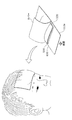
- FIG. 3 shows an example in which the biological signal measuring apparatus 10 according to the present embodiment is worn by a subject.
- the biological signal measuring device 10 further covered with a cover not shown in FIG. 2 from the top of the rechargeable battery 320 is pasted so that the surface of the pasting part main body 115a is in contact with the forehead of the subject.
- the biological signal measuring apparatus 10 according to the present embodiment is used by being attached to the forehead like a commercially available cooling gel sheet.
- a mobile information terminal or storage device such as a notebook personal computer, tablet, or smartphone as the transmission destination of the measurement data, it is possible to further reduce the limit of the subject's action range.
- the electrodes are fixed to the subject's head via a fixture using elastic resin or rubber.
- such fixtures have upper and lower limits on the size of the head that can be applied.
- the electrode can be fixed to the subject's head without using such a fixture, so that it can be used for an infant with a small head circumference, for example.
- the force to squeeze the head like an elastic fixture does not work, there is a possibility that it can be used even if the head of the subject is injured, for example. It is higher than the electroencephalograph.
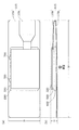
- FIG. 4 is a diagram illustrating a configuration example of the pasting unit 115 including the signal acquisition unit 110 and the substrate 500 of the biological signal measuring apparatus 10 according to the present embodiment illustrated in FIG. 2. This figure shows a state where the affixing part 115 and the substrate 500 are connected via the connector 350 in a state where the affixing part 115 is not folded back.
- the pasting unit 115 is arranged with two parallel rows of four signal acquisition units 110 extending in the longitudinal direction of the pasting unit 115.
- a hatched line extending from each signal acquisition unit 110 to the right end of the connection unit 115b indicates a wiring that is a path of a biological signal. Note that the shape, number, number of columns, and positional relationship between the signal acquisition units 110 of the signal acquisition unit 110 are not limited to this example. Also, the wiring pattern is not limited to the example shown in this figure.
- these signal acquisition units 110 include a reference electrode for acquiring a reference potential and a measurement electrode for measuring a potential difference from the reference potential at each location.
- the signal acquisition unit 110a may be a reference electrode
- the signal acquisition unit 110b may be a measurement electrode that measures a potential difference from a reference potential acquired by the signal acquisition unit 110a. That is, the signal acquisition unit 110a is a reference electrode of the signal acquisition unit 110b that is a measurement electrode.
- the signal acquisition unit 110c is a reference electrode of the signal acquisition unit 110d that is a measurement electrode
- the signal acquisition unit 110e is a reference electrode of the signal acquisition unit 110f that is a measurement electrode
- the signal acquisition unit 110g is a measurement electrode.
- the reference electrode of the signal acquisition unit 110h may be used.
- the biological signal measuring apparatus 10 can measure biological signals with four channels.
- the signal acquisition unit 110a may be a reference electrode of the signal acquisition units 110b to 110h that are measurement electrodes.
- the biological signal measuring apparatus 10 can measure the biological signal with 7 channels. Note that the number of signal acquisition units 110 is not limited to this example as described above, and it is possible to perform measurement with more channels using more signal acquisition units 110.
- the plurality of signal acquisition units 110 include electrodes that can be attached to and detached from the pasting unit 115, and these electrodes may be used as reference electrodes for measuring a reference potential at a place other than the forehead such as an earlobe. Good.
- the signal acquisition unit 110a may be a reference electrode that can be separated from the pasting unit main body 115a.
- FIG. 5 is a diagram illustrating another example of the configuration of the pasting unit 115 including the signal acquisition unit 110 and the substrate 500 of the biological signal measuring apparatus 10 according to the present embodiment illustrated in FIG. 2.
- FIG. 5 shows a state where the signal acquisition unit 110a pasted at the position indicated by the broken line is peeled off from the pasting unit main body 115a and separated.
- the signal acquisition unit 110 separated from the pasting unit main body 115a also maintains the connection with the wiring that is the signal path.
- the signal acquisition part 110 once peeled off from the sticking part main body 115a can be stuck on the sticking part 115 again by the adhesiveness of the sticking part 115.
- the connecting portion 115b has flexibility, but the degree of flexibility may be changed depending on the location.
- the urging force in the handling of the biological signal measuring apparatus 10 and the stress due to the deformation of the connecting portion 115 b are concentrated on the tip portion of the connecting portion 115 b to be engaged with the connector 350 for connection with the substrate 500.
- the connection part 115b is a flexible material like the sticking part main body 115a, this tip part is easily damaged by this stress.
- the connection part 115b may have a configuration in which the hardness increases as it approaches the tip from a part close to the signal acquisition part 110 (the pasting part main body 115a). For example, in FIG.
- the range of A that is, the portion close to the sticking portion main body 115a in the sticking portion main body 115a and the connecting portion 115b is the flexible silicone material having the above-described stretchability in common.
- range B it is made of a plastic resin that has flexibility to the extent that it can be easily bent, but does not have elasticity as in the range A, and further, in the range C that includes the tip of the connecting portion 115b, Like the range, there is no elasticity and flexibility, but it may be made of a plastic resin harder than the plastic resin in the range B. In this configuration, the stress as described above is not concentrated on the tip portion of the connecting portion 115b, but is distributed to the portion where the material is switched in the connecting portion 115b. Thereby, the damage of the connection part 115b by stress can be delayed and the useful life of the sticking part 115 can be extended.
- the signal processing circuit is mounted on the substrate 500 as described above.
- the signal processing circuit here includes an amplification unit 120 and an A / D converter 130 in the input unit 100, a control unit 200, a charging circuit 310 in the power supply unit 300, and an output unit 400.
- the amplification unit 120 and the A / D converter 130 that process an analog signal obtained by measuring a potential on the body surface of a living body and convert the analog signal into a digital signal are supplied to the analog circuit.
- the CPU 210 of the control unit 200, the baseband DSP 220, the contact state detection unit 230, the clock generation unit 240, and the output unit 400 that wirelessly transmits the processed digital signal, which are related to the processing, are connected to the digital circuit, the analog circuit, and the digital circuit.
- the power supply management unit 250 and the power stabilization unit 260 of the control unit 200 and the charging circuit 310 and the rechargeable battery 320 of the power supply unit 300 that supply power to the circuit are divided into power supply circuits.
- These analog circuit, digital circuit, and power supply circuit are respectively mounted in the first region, the second region, and the third region in regions obtained by dividing the mounting surface of the substrate 500 into three regions. For example, in FIG.
- the range indicated by a is the first region
- the range indicated by c is the second region
- the range indicated by b is the third region.
- each region obtained by dividing the substrate 500 are substantially the same, but the method of dividing the substrate 500 is not limited to this example in the present invention.
- the substrate 500 may not be one physically continuous flexible substrate.
- each or part of the first to third regions may be mounted on separate flexible boards, and these flexible boards may be connected by wiring for transmitting signals and power.
- the rechargeable battery 320 may not be mounted on the substrate 500.
- it may be mounted on the substrate 500 via a holder provided on the substrate 500, or may be connected to a flexible substrate via a cable as shown in FIG.
- the substrate 500 is a flexible substrate, but the substrate 500 is not limited to a flexible substrate. That is, the substrate 500 may be a rigid substrate. Even if the substrate 500 is a rigid substrate, by making the size of the biological signal measuring apparatus 10 as small as possible, the uncomfortable feeling that the substrate 500 gives to the subject via the cushion 600 and the attaching portion 115 can be suppressed.
- the biological signal measuring apparatus 10 is extremely small compared to a conventional medical electroencephalogram measuring apparatus and can be easily used. However, if the accuracy of the biological signal measured using this is not sufficient, it is not suitable for use as a medical device.
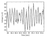
- FIG. 6A and 6B show both the biological signal measuring apparatus 10 according to the present embodiment and a medical electroencephalogram measuring apparatus (manufactured by Nihon Kohden Corporation, Neurofax (registered trademark) EEG-1200, hereinafter referred to as Neurofax).
- FIG. 6A is an electroencephalogram of an electroencephalogram measured in a state where the subject has his eyes open
- FIG. 6B is a state in which the subject has his eyes open.
- a solid line indicates an electroencephalogram acquired by the biological signal measuring apparatus 10 according to the present embodiment
- a broken line indicates an electroencephalogram acquired by Neurofax.
- the electroencephalograms acquired by both devices showed high agreement.
- the result of the frequency analysis of the acquired electroencephalogram showed a high agreement, and a high correlation with a correlation coefficient of 0.99 or more was observed between the electroencephalograms acquired by both apparatuses.
- the biological signal measuring apparatus 10 according to this embodiment can measure even a weak potential change such as an electroencephalogram with the same accuracy as that of a medical electroencephalogram measuring apparatus.
- the biological signal measuring apparatus 10 used as an electroencephalograph according to the present embodiment is less burdensome on the subject wearing the electroencephalograph for other uses for medical purposes and can easily measure the electroencephalogram.
- it since it can be moved while wearing and can perform a certain amount of work, it can be used as a so-called wearable device to constantly measure brain waves in a state close to everyday life.
- the biological signal measuring device 10 as such an electroencephalograph is, for example, a quantitative evaluation based on brain activity data of the sleep state management at home of a patient with sleep apnea syndrome, the ability of an elderly person to drive a car or perform mechanical work, Use for research such as dementia with abnormal brain activity, Parkinson's disease, epilepsy, mental illness, diagnosis and monitoring by quantitative assessment of brain activity, monitoring of anesthesia depth during surgery, brain developmental science, etc. Can do.
- it can be used to collect data on quantitative changes in brain activity due to the administration of nervous system drugs.
- it can be used for collecting data serving as an index for selecting a drug optimal for a patient from a plurality of drugs for the same purpose in a medical field.
- the biological signal measuring device 10 used as an electroencephalograph has been described.
- the biological signal measuring device 10 is a biological signal based on various potentials such as an electrocardiograph, an electrocardiograph, and an electromyograph. It can be applied to other measuring instruments.
- the biological signal measuring device 10 is provided as a device that can be measured with sufficient accuracy and with sufficient accuracy as compared with conventional devices.
- the biological signal measuring device 10 provided as a biological signal measuring device other than these electroencephalograms has the basic configuration as described in the above embodiment, and the number and arrangement of the signal acquisition units 110 that are electrodes.
- the shape and size of the pasting part 115 covering the measurement site, a processing algorithm for visualizing the acquired biological signal, and the like are appropriately changed and adjusted.
- Such a measuring device can be used, for example, as an electromyograph of a pregnant woman's uterus at home for early detection of the timing of childbirth. Further, it can be used as a means for monitoring when there is an abnormality in the health condition of the fetus, or as a fetal heart rate monitor as a communication tool with the fetus.
- the biological signal measuring apparatus 10 can be used to collect physical control data in sports and rehabilitation.
- the advantage of the biological signal measuring apparatus 10 according to the present invention that measurement can be continued even if some electrodes are removed due to movement. It becomes.
- the shape and size of the sticking unit 115 are determined depending on, for example, the number and arrangement of the signal acquisition units 110 according to each use, the stability of the biological signal measuring device 10 in the mounted state, and the like. This is appropriately determined in consideration of the wearing feeling generated in the subject, and is not limited to the above-described embodiment.
- the present invention has been described using the embodiments and examples as a biological signal measuring device used for a human body, it can also be applied to measurement of a living body other than the human body or a potential change other than the living body. For example, it can be used for crop growth management by monitoring changes in the potential difference on the surface of the plant, or it can be used to inspect internal conditions such as internal corrosion by mapping the potential difference on the surface of the concrete part of the building. can do.
- the shape and size of the pasting unit 115 are, for example, the number and arrangement of the signal acquisition units 110 according to each application, and the stability of the biological signal measurement device 10 in the installed state. Is determined as appropriate, and is not limited to the above embodiment.
- the biological signal measuring device 10 described above may not include the cushion 600 between the substrate 500 and the pasting portion 115.
- the substrate 500 may be directly fixed to the sticking portion 115 or may be fixed to the cover shown in FIG.
- the substrate 500 and the pasting portion 115 do not necessarily have to be disposed so as to overlap each other. For example, as shown in FIG. 4, it may be used in a state where it is unfolded at the connecting portion.
- the biological signal measuring device 10 may further include a storage device for storing biological signal data.
- This storage device is used as a temporary storage location for data when wireless communication with the outside is impossible, for example.
- This data may be output to the outside via the output unit 400 in a state where wireless communication is possible.
- the biological signal measuring device 10 may be configured to output even a detachable communication cable. For example, data may be output from a cable connected to a USB port included in the charging circuit 310.
- energy generation using light or vibration may be used as a power source.
- continuous use time can be extended.
- the duration of the battery can be adjusted by changing the number of channels, the sampling rate of the analog signal, and the like within a range where necessary measurement data can be acquired according to the purpose.
- the signal acquisition unit 110 that is an electrode and the pasting unit 115 that is a sheet on which wiring is formed may be any material that can be freely expanded and contracted and has adhesiveness as described above. It is not limited to materials.
- the sticking portion 115 may be a sheet having similar characteristics using a material such as resin, rubber, fiber (cloth), or a combination thereof, such as a bandage.
- the material used for the signal acquisition unit 110 and the expandable conductor that is the material of the wiring is not limited to the silver nanowire. Instead of nanowires or carbon nanofibers of other metals such as gold or copper, which are conductors, these may be used in combination.
- the present invention can be used as a biological signal measuring device such as an electroencephalograph, an electrocardiograph, an electrocardiograph, an electromyograph, etc., and for measuring the potential on the surface of a structure even if it is not a living body. It can be used as a device.
- Biosignal measuring device 100 Input part 110, 110a-110h Signal acquisition part 115 Pasting part 115a Pasting part main body 115b Connection part 120 Amplifying part 130 A / D converter 200 Control part 210 CPU 220 Baseband DSP 230 Contact State Detection Unit 240 Clock Generation Unit 250 Power Management Unit 260 Power Stabilization Unit 300 Power Supply Unit 310 Charging Circuit 320 Rechargeable Battery 330 Connection Terminal 350 Connector 400 Output Unit 500 Substrate 600 Cushion 700 Cable
Landscapes
- Health & Medical Sciences (AREA)
- Life Sciences & Earth Sciences (AREA)
- Engineering & Computer Science (AREA)
- Heart & Thoracic Surgery (AREA)
- Molecular Biology (AREA)
- Biophysics (AREA)
- Pathology (AREA)
- Biomedical Technology (AREA)
- Veterinary Medicine (AREA)
- Medical Informatics (AREA)
- Physics & Mathematics (AREA)
- Surgery (AREA)
- Animal Behavior & Ethology (AREA)
- General Health & Medical Sciences (AREA)
- Public Health (AREA)
- Computer Networks & Wireless Communication (AREA)
- Psychiatry (AREA)
- Psychology (AREA)
- Measurement And Recording Of Electrical Phenomena And Electrical Characteristics Of The Living Body (AREA)
Abstract
Description
[1.全体構成]
図1は、本実施の形態に係る生体信号計測装置10の構成の概要を示すブロック図である。
上記の構成を有する生体信号計測装置10は、上述のとおり、脳波計、心電計、筋電計等として用いることができる。以下では、本実施の形態に係る生体信号計測装置10の実施例として、脳波計として用いられる生体信号計測装置10を具体的に説明する。
図2は、脳波計として用いられる生体信号計測装置10の外観を示す模式図である。本図の(a)は平面図、(b)は正面図である。なお、図1で示された構成要素の一部は、本図では見やすさのために図示が省略されている。例えば貼付部115は透明であってその裏面側からも信号取得部110が視認可能であってもよいが、本図では信号取得部110の図示を省略している。なお、(b)に示される図で下側の面が表面であり、この面が被検者の額に接触するように貼り付けて装着される。
図4は、図2に示される本実施例に係る生体信号計測装置10の、信号取得部110を含む貼付部115及び基板500の構成例を示す図である。本図では、貼付部115を折り返さない状態で、貼付部115と基板500とがコネクタ350を介して接続されている様子が示されている。
基板500には、上述のとおり信号処理回路が実装されている。ここでいう信号処理回路には、入力部100のうちの増幅部120とA/D変換器130、制御部200、電源部300のうちの充電回路310、及び出力部400が含まれる。これらの構成要素のうち、生体の体表での電位の計測によって得られたアナログ信号を処理してデジタル信号に変換する増幅部120及びA/D変換器130はアナログ回路に、このデジタル信号の処理に関連する、制御部200のCPU210、ベースバンドDSP220、接触状態検出部230、及びクロック生成部240、並びに処理されたデジタル信号を無線で送信する出力部400はデジタル回路に、アナログ回路及びデジタル回路に電力を供給する、制御部200の電源管理部250及び電力安定部260、並びに電源部300の充電回路310及び充電池320は電源回路に分けられる。そして、これらのアナログ回路、デジタル回路、及び電源回路は、基板500の実装面を3つの領域に分割して得られる領域に第1領域、第2領域、及び第3領域にそれぞれ実装される。例えば図4においてaで示される範囲が第1領域、cで示される範囲が第2領域、bで示される範囲が第3領域である。このようにアナログ回路の領域とデジタル回路の領域とを分けることで、一方で発生するノイズの他方へのまわり込みを抑えている。また、アナログ回路とデジタル回路とでは駆動電力の電圧が異なるため、充電池320からの出力系統はアナログ回路とでデジタル回路とで分けられる。一方でGNDラインはアナログ回路とでデジタル回路とで共通である。したがって、このようにアナログ回路とデジタル回路が実装される領域を分け、基板500内で極力離すことでノイズの影響を抑えている。
本実施例に係る生体信号計測装置10は、従来の医療用の脳波計測装置に比べてごく小さく、かつ簡便に利用が可能である。しかし、これを用いて計測される生体信号の精度が十分でなければ、医療機器としての用途に適さない。
本実施例に係る、脳波計として用いられる生体信号計測装置10は、従来の医療用その他用途の脳波計に比べて装着している被検者の負担が小さく、簡便に脳波の計測ができる。また装着したままの移動やある程度の作業が可能であることから、いわゆるウェアラブル機器として用いて日常生活に近い状態での脳波の常時計測を可能にする。
上記の実施例では脳波計として用いられる生体信号計測装置10について説明したが、上述のとおり、生体信号計測装置10は心電計、眼電計、筋電計等の各種の電位に基づく生体信号の計測機器に適用できる。そして生体信号計測装置10は、これらの計測機器としても、従来の機器に比べて装着感が少なく、かつ十分な精度での計測が可能な機器として提供される。
以上、本発明に係る生体信号計測装置について実施の形態及び実施例を用いて説明したが、本発明は上記の実施の形態及び実施例に限定されない。以下に、本発明に係る生体信号計測装置に加えられる変形例を挙げる。
100 入力部
110、110a~110h 信号取得部
115 貼付部
115a 貼付部本体
115b 接続部
120 増幅部
130 A/D変換器
200 制御部
210 CPU
220 ベースバンドDSP
230 接触状態検出部
240 クロック生成部
250 電源管理部
260 電力安定部
300 電源部
310 充電回路
320 充電池
330 接続端子
350 コネクタ
400 出力部
500 基板
600 クッション
700 ケーブル
Claims (11)
- 生体に貼り付けて用いられる生体信号計測装置であって、
複数の電極と前記複数の電極のそれぞれと接続される複数の配線とが形成され、伸縮及び屈曲自在で、かつ、粘着性を有するシートと、
前記複数の配線に接続され、前記複数の配線を介して得られる生体信号を無線で送信する信号処理回路が実装された基板とを備え、
前記複数の電極は、前記シートの表面に露出しており、
前記シートと前記基板とは、前記シートの裏面と前記基板とが対向するように重ねられる
生体信号計測装置。 - 前記シートの表面が前記生体に貼り付けられた状態で前記シート及び前記基板を平面視したときの外形は、5cm×15cmの矩形に収まる大きさである
請求項1記載の生体信号計測装置。 - 前記複数の電極には、基準電極と、複数の計測電極とが含まれる
請求項1又は2記載の生体信号計測装置。 - 前記基準電極は、前記シートと着脱可能な態様で、前記シートに貼り付けられている
請求項3記載の生体信号計測装置。 - 前記複数の電極には、複数の電極の並びからなる列が少なくとも2列で並行して配置された電極が含まれる
請求項1~4のいずれか1項に記載の生体信号計測装置。 - 前記シートは、可撓性のある接続部を有し、
前記複数の配線のそれぞれは、対応する前記電極から前記接続部まで延びており、
前記接続部は、前記シートを折り返すように曲げられ、当該接続部の先端が前記信号処理回路に接続されている
請求項1~5のいずれか1項に記載の生体信号計測装置。 - 前記シートが有する前記接続部は、前記複数の電極に近い箇所から前記先端に近くなるほど硬度が増す
請求項6記載の生体信号計測装置。 - 前記信号処理回路は、前記複数の電極を介して得られるアナログ信号を処理してデジタル信号に変換するアナログ回路と、前記アナログ回路で得られたデジタル信号を処理して無線で送信するデジタル回路と、前記アナログ回路及び前記デジタル回路に電力を供給する電源回路とを有し、
前記アナログ回路、前記デジタル回路及び前記電源回路は、前記基板の実装面を3つの領域に分割して得られる第1領域、第2領域及び第3領域にそれぞれ実装されている
請求項1~7のいずれか1項に記載の生体信号計測装置。 - 前記アナログ回路は、前記アナログ信号を20ビット以上のビット数のデジタル信号に変換するA/D変換器を有する
請求項8記載の生体信号計測装置。 - 前記アナログ回路は、前記複数の電極と前記生体との接触インピーダンスを計測することによって前記複数の電極と前記生体との接触状態を検出する接触状態検出回路を有する
請求項8記載の生体信号計測装置。 - 前記電源回路は、
充電可能な電池と、
前記基板に設けられた接続端子と、
前記接続端子から供給される電力で前記電池を充電する充電回路とを有する
請求項8記載の生体信号計測装置。
Priority Applications (4)
| Application Number | Priority Date | Filing Date | Title |
|---|---|---|---|
| EP16884982.6A EP3403576B1 (en) | 2016-01-12 | 2016-08-05 | Biosignal measurement apparatus |
| US16/069,503 US11234645B2 (en) | 2016-01-12 | 2016-08-05 | Biosignal measurement apparatus |
| JP2017561508A JP6629887B2 (ja) | 2016-01-12 | 2016-08-05 | 生体信号計測装置 |
| US17/588,028 US11883200B2 (en) | 2016-01-12 | 2022-01-28 | Biosignal measurement apparatus |
Applications Claiming Priority (2)
| Application Number | Priority Date | Filing Date | Title |
|---|---|---|---|
| JP2016003958 | 2016-01-12 | ||
| JP2016-003958 | 2016-01-12 |
Related Child Applications (2)
| Application Number | Title | Priority Date | Filing Date |
|---|---|---|---|
| US16/069,503 A-371-Of-International US11234645B2 (en) | 2016-01-12 | 2016-08-05 | Biosignal measurement apparatus |
| US17/588,028 Continuation US11883200B2 (en) | 2016-01-12 | 2022-01-28 | Biosignal measurement apparatus |
Publications (1)
| Publication Number | Publication Date |
|---|---|
| WO2017122379A1 true WO2017122379A1 (ja) | 2017-07-20 |
Family
ID=59311115
Family Applications (1)
| Application Number | Title | Priority Date | Filing Date |
|---|---|---|---|
| PCT/JP2016/073112 Ceased WO2017122379A1 (ja) | 2016-01-12 | 2016-08-05 | 生体信号計測装置 |
Country Status (4)
| Country | Link |
|---|---|
| US (2) | US11234645B2 (ja) |
| EP (1) | EP3403576B1 (ja) |
| JP (3) | JP6629887B2 (ja) |
| WO (1) | WO2017122379A1 (ja) |
Cited By (5)
| Publication number | Priority date | Publication date | Assignee | Title |
|---|---|---|---|---|
| WO2019211957A1 (ja) * | 2018-05-02 | 2019-11-07 | 国立大学法人大阪大学 | 電極シート |
| US10499497B2 (en) | 2017-11-27 | 2019-12-03 | Nippon Mektron, Ltd. | Stretchable circuit board and stretchable circuit board manufacturing method |
| WO2023281664A1 (ja) * | 2021-07-07 | 2023-01-12 | 株式会社オクチィ | 生体信号測定用電極及び測定装置 |
| WO2024190471A1 (ja) | 2023-03-13 | 2024-09-19 | 国立大学法人神戸大学 | 生体信号処理システム、信号処理装置、コンピュータプログラム、生体信号の生成方法 |
| WO2025033409A1 (ja) * | 2023-08-09 | 2025-02-13 | オムロン株式会社 | 生体信号計測装置 |
Families Citing this family (9)
| Publication number | Priority date | Publication date | Assignee | Title |
|---|---|---|---|---|
| US11419549B2 (en) * | 2018-05-16 | 2022-08-23 | Murata Manufacturing Co., Ltd. | Sticking-type device for living body |
| JP6523542B1 (ja) * | 2018-12-03 | 2019-06-05 | プロトマーケティング株式会社 | 胎動検知装置及び胎動検知システム |
| US11786694B2 (en) | 2019-05-24 | 2023-10-17 | NeuroLight, Inc. | Device, method, and app for facilitating sleep |
| GB2585083B (en) * | 2019-06-28 | 2022-08-24 | Prevayl Innovations Ltd | Biosensing textile and garment |
| JP7767288B2 (ja) | 2019-12-23 | 2025-11-11 | アリメトリー リミテッド | 電極パッチおよび接続システム |
| EP4153032A1 (en) * | 2020-05-22 | 2023-03-29 | Given Imaging Ltd. | Adhesion detection for a medical patch |
| WO2022250793A1 (en) * | 2021-05-24 | 2022-12-01 | Crestmont Ventures, Inc. | Electromyographic bruxism training |
| JP7837016B2 (ja) | 2022-03-22 | 2026-03-30 | 学校法人法政大学 | 生体情報取得システム、及び、電極シート |
| CN119523421B (zh) * | 2024-11-27 | 2026-03-06 | 浙江大学 | 用于胃肠道内气体分子原位实时检测的摄入式传感检测胶囊 |
Citations (3)
| Publication number | Priority date | Publication date | Assignee | Title |
|---|---|---|---|---|
| JP2007125104A (ja) * | 2005-11-01 | 2007-05-24 | Kyokko Denki Kk | センサ信号インターフェース装置とそれを用いたロボット用インターフェースシステム |
| WO2010029966A1 (ja) * | 2008-09-10 | 2010-03-18 | 国立大学法人筑波大学 | 生体信号計測装着具及び装着式動作補助装置 |
| JP2014505529A (ja) * | 2010-12-22 | 2014-03-06 | カーディオインサイト テクノロジーズ インコーポレイテッド | 多層センサー装置 |
Family Cites Families (19)
| Publication number | Priority date | Publication date | Assignee | Title |
|---|---|---|---|---|
| JPS5926604U (ja) * | 1982-08-12 | 1984-02-18 | セノ−株式会社 | 生体用電極 |
| JP3417049B2 (ja) * | 1994-04-11 | 2003-06-16 | カシオ計算機株式会社 | 心電計 |
| US6032064A (en) * | 1996-10-11 | 2000-02-29 | Aspect Medical Systems, Inc. | Electrode array system for measuring electrophysiological signals |
| JP2001212092A (ja) * | 2000-02-07 | 2001-08-07 | Sekisui Chem Co Ltd | 電気特性測定装置 |
| WO2002030261A2 (en) | 2000-10-09 | 2002-04-18 | Brainz Instruments Limited | Sensor assembly for monitoring an infant brain |
| US8620402B2 (en) * | 2003-10-30 | 2013-12-31 | Halthion Medical Technologies, Inc. | Physiological sensor device |
| JP2007105316A (ja) | 2005-10-14 | 2007-04-26 | Konica Minolta Sensing Inc | 生体情報測定器 |
| AU2011254054B2 (en) * | 2005-11-16 | 2013-08-22 | Bioness Neuromodulation Ltd. | Gait modulation system and method |
| US8214007B2 (en) * | 2006-11-01 | 2012-07-03 | Welch Allyn, Inc. | Body worn physiological sensor device having a disposable electrode module |
| US20090062670A1 (en) * | 2007-08-30 | 2009-03-05 | Gary James Sterling | Heart monitoring body patch and system |
| US8628020B2 (en) * | 2007-10-24 | 2014-01-14 | Hmicro, Inc. | Flexible wireless patch for physiological monitoring and methods of manufacturing the same |
| US9579055B1 (en) * | 2008-10-17 | 2017-02-28 | Orbital Research Inc. | Apparatus for non-invasive fetal biosignal acquisition |
| JP5884394B2 (ja) * | 2011-10-14 | 2016-03-15 | ソニー株式会社 | ヘッドバンド、ヘッドギア及び脳波測定装置 |
| JP2013121489A (ja) * | 2011-11-11 | 2013-06-20 | Midori Anzen Co Ltd | 睡眠状態検出装置、睡眠状態演算装置、及び睡眠状態検出システム |
| US9510762B2 (en) | 2012-09-04 | 2016-12-06 | Lkc Technologies, Inc. | Electrode arrays |
| US10413251B2 (en) * | 2012-10-07 | 2019-09-17 | Rhythm Diagnostic Systems, Inc. | Wearable cardiac monitor |
| JP6711750B2 (ja) | 2013-11-22 | 2020-06-17 | エムシー10 インコーポレイテッドMc10,Inc. | 心臓活動の検知および分析のためのコンフォーマルセンサシステム |
| US9498129B2 (en) * | 2014-03-17 | 2016-11-22 | Cardiac Technologies International, Inc. | Method and device for patient monitoring using dynamic multi-function device |
| US20160066808A1 (en) * | 2014-09-08 | 2016-03-10 | Cardiac Technologies International, Inc. | Method and Device for Patient Monitoring Using Dynamic Multi-Function Device |
-
2016
- 2016-08-05 JP JP2017561508A patent/JP6629887B2/ja active Active
- 2016-08-05 WO PCT/JP2016/073112 patent/WO2017122379A1/ja not_active Ceased
- 2016-08-05 EP EP16884982.6A patent/EP3403576B1/en active Active
- 2016-08-05 US US16/069,503 patent/US11234645B2/en active Active
-
2019
- 2019-12-03 JP JP2019218923A patent/JP6889941B2/ja active Active
-
2021
- 2021-02-16 JP JP2021022697A patent/JP7023023B2/ja active Active
-
2022
- 2022-01-28 US US17/588,028 patent/US11883200B2/en active Active
Patent Citations (3)
| Publication number | Priority date | Publication date | Assignee | Title |
|---|---|---|---|---|
| JP2007125104A (ja) * | 2005-11-01 | 2007-05-24 | Kyokko Denki Kk | センサ信号インターフェース装置とそれを用いたロボット用インターフェースシステム |
| WO2010029966A1 (ja) * | 2008-09-10 | 2010-03-18 | 国立大学法人筑波大学 | 生体信号計測装着具及び装着式動作補助装置 |
| JP2014505529A (ja) * | 2010-12-22 | 2014-03-06 | カーディオインサイト テクノロジーズ インコーポレイテッド | 多層センサー装置 |
Non-Patent Citations (1)
| Title |
|---|
| See also references of EP3403576A4 * |
Cited By (10)
| Publication number | Priority date | Publication date | Assignee | Title |
|---|---|---|---|---|
| US10499497B2 (en) | 2017-11-27 | 2019-12-03 | Nippon Mektron, Ltd. | Stretchable circuit board and stretchable circuit board manufacturing method |
| WO2019211957A1 (ja) * | 2018-05-02 | 2019-11-07 | 国立大学法人大阪大学 | 電極シート |
| CN112055559A (zh) * | 2018-05-02 | 2020-12-08 | 国立大学法人大阪大学 | 电极片 |
| JPWO2019211957A1 (ja) * | 2018-05-02 | 2021-05-13 | 国立大学法人大阪大学 | 電極シート |
| JP7208651B2 (ja) | 2018-05-02 | 2023-01-19 | 国立大学法人大阪大学 | 電極シート |
| US12121356B2 (en) | 2018-05-02 | 2024-10-22 | Osaka University | Electrode sheet |
| WO2023281664A1 (ja) * | 2021-07-07 | 2023-01-12 | 株式会社オクチィ | 生体信号測定用電極及び測定装置 |
| WO2024190471A1 (ja) | 2023-03-13 | 2024-09-19 | 国立大学法人神戸大学 | 生体信号処理システム、信号処理装置、コンピュータプログラム、生体信号の生成方法 |
| EP4681644A1 (en) | 2023-03-13 | 2026-01-21 | National University Corporation Kobe University | Biological-signal-processing system, signal-processing device, computer program, and method for generating biological signal |
| WO2025033409A1 (ja) * | 2023-08-09 | 2025-02-13 | オムロン株式会社 | 生体信号計測装置 |
Also Published As
| Publication number | Publication date |
|---|---|
| JP7023023B2 (ja) | 2022-02-21 |
| EP3403576A4 (en) | 2019-06-05 |
| US20190029595A1 (en) | 2019-01-31 |
| US11234645B2 (en) | 2022-02-01 |
| US11883200B2 (en) | 2024-01-30 |
| EP3403576B1 (en) | 2023-06-21 |
| JP6629887B2 (ja) | 2020-01-15 |
| JP6889941B2 (ja) | 2021-06-18 |
| JP2021074627A (ja) | 2021-05-20 |
| US20220142577A1 (en) | 2022-05-12 |
| JP2020039917A (ja) | 2020-03-19 |
| JPWO2017122379A1 (ja) | 2018-12-20 |
| EP3403576A1 (en) | 2018-11-21 |
Similar Documents
| Publication | Publication Date | Title |
|---|---|---|
| JP7023023B2 (ja) | 生体信号計測装置 | |
| US12588822B2 (en) | Remote physiological monitor | |
| Majumder et al. | Noncontact wearable wireless ECG systems for long-term monitoring | |
| JP5124602B2 (ja) | 生体信号測定装置 | |
| EP2916730B1 (en) | Arrangement for carrying out electrode measurements | |
| KR100592934B1 (ko) | 착용형 생체신호 검출모듈 및 이를 포함한 측정장치 | |
| US20220054820A1 (en) | Wearable devices | |
| US20170127966A1 (en) | Electrode device for wearable or handheld apparatus | |
| Dai et al. | A low-power and miniaturized electrocardiograph data collection system with smart textile electrodes for monitoring of cardiac function | |
| Kim et al. | Wireless, skin-like membrane electronics with multifunctional ergonomic sensors for enhanced pediatric care | |
| Liu et al. | Soft wearable sensors for monitoring symptoms of COVID-19 and other respiratory diseases: a review | |
| Srinivasa et al. | Dry electrodes for bio-potential measurement in wearable systems | |
| KR102171566B1 (ko) | 생체 신호 측정 방법, 장치 및 컴퓨터 프로그램 | |
| JP3413521B1 (ja) | 心電図用電極装着帯 | |
| McEWAN et al. | Wearable dry sensors with bluetooth connection for use in remote patient monitoring systems | |
| WO2017060560A1 (en) | Arrangement for carrying out electrode measurements | |
| Yeo et al. | Skin-like electronics for a persistent brain-computer interface | |
| Wongdhamma et al. | Wireless wearable multi-sensory system for monitoring of sleep apnea and other cardiorespiratory disorders | |
| Sheeraz et al. | Flexible wearable biopatches for physiological monitoring using dry thin gold film electrodes | |
| Bao et al. | Wearable health monitoring system using flexible materials electrodes | |
| Liu | Flexible sensors for wearable cardiac monitoring system: a review | |
| WO2024090527A1 (ja) | 生体信号計測装置 | |
| Kim et al. | Wireless Soft Hybrid Electronics for Safe and Effective Cardiac Monitoring in Pediatric Care | |
| Kankipati | Multifunctional wearable epidermal device for physiological signal monitoring in sleep study | |
| JP2008229320A (ja) | 超小型無線生体信号処理装置及びその用途 |
Legal Events
| Date | Code | Title | Description |
|---|---|---|---|
| 121 | Ep: the epo has been informed by wipo that ep was designated in this application |
Ref document number: 16884982 Country of ref document: EP Kind code of ref document: A1 |
|
| WWE | Wipo information: entry into national phase |
Ref document number: 2017561508 Country of ref document: JP |
|
| NENP | Non-entry into the national phase |
Ref country code: DE |
|
| WWE | Wipo information: entry into national phase |
Ref document number: 2016884982 Country of ref document: EP |
|
| ENP | Entry into the national phase |
Ref document number: 2016884982 Country of ref document: EP Effective date: 20180813 |