WO2017119477A1 - Imaging element and imaging device - Google Patents
Imaging element and imaging device Download PDFInfo
- Publication number
- WO2017119477A1 WO2017119477A1 PCT/JP2017/000247 JP2017000247W WO2017119477A1 WO 2017119477 A1 WO2017119477 A1 WO 2017119477A1 JP 2017000247 W JP2017000247 W JP 2017000247W WO 2017119477 A1 WO2017119477 A1 WO 2017119477A1
- Authority
- WO
- WIPO (PCT)
- Prior art keywords
- pixel
- photoelectric conversion
- electrode
- unit
- pixels
- Prior art date
Links
- 238000003384 imaging method Methods 0.000 title claims abstract description 140
- 238000006243 chemical reaction Methods 0.000 claims abstract description 489
- 230000035945 sensitivity Effects 0.000 claims description 36
- 230000003287 optical effect Effects 0.000 claims description 35
- 230000003595 spectral effect Effects 0.000 claims description 31
- 238000001514 detection method Methods 0.000 claims description 20
- 210000001747 pupil Anatomy 0.000 claims description 7
- 239000004065 semiconductor Substances 0.000 claims description 5
- 239000000758 substrate Substances 0.000 claims description 5
- 230000003321 amplification Effects 0.000 description 32
- 238000003199 nucleic acid amplification method Methods 0.000 description 32
- 230000005484 gravity Effects 0.000 description 19
- 238000010586 diagram Methods 0.000 description 14
- 230000004048 modification Effects 0.000 description 11
- 238000012986 modification Methods 0.000 description 11
- 239000011295 pitch Substances 0.000 description 11
- 239000004973 liquid crystal related substance Substances 0.000 description 6
- 238000009825 accumulation Methods 0.000 description 5
- 239000002131 composite material Substances 0.000 description 5
- 230000000694 effects Effects 0.000 description 5
- 230000000295 complement effect Effects 0.000 description 3
- 238000000034 method Methods 0.000 description 3
- 239000000203 mixture Substances 0.000 description 3
- 230000004044 response Effects 0.000 description 3
- 239000003086 colorant Substances 0.000 description 2
- 230000004907 flux Effects 0.000 description 2
- 230000006870 function Effects 0.000 description 2
- 230000008569 process Effects 0.000 description 2
- 230000002194 synthesizing effect Effects 0.000 description 2
- 230000015572 biosynthetic process Effects 0.000 description 1
- 230000008859 change Effects 0.000 description 1
- 230000006835 compression Effects 0.000 description 1
- 238000007906 compression Methods 0.000 description 1
- 239000000284 extract Substances 0.000 description 1
- 230000007274 generation of a signal involved in cell-cell signaling Effects 0.000 description 1
- 230000002093 peripheral effect Effects 0.000 description 1
- 238000003786 synthesis reaction Methods 0.000 description 1
Images


Classifications
-
- H—ELECTRICITY
- H01—ELECTRIC ELEMENTS
- H01L—SEMICONDUCTOR DEVICES NOT COVERED BY CLASS H10
- H01L27/00—Devices consisting of a plurality of semiconductor or other solid-state components formed in or on a common substrate
- H01L27/14—Devices consisting of a plurality of semiconductor or other solid-state components formed in or on a common substrate including semiconductor components sensitive to infrared radiation, light, electromagnetic radiation of shorter wavelength or corpuscular radiation and specially adapted either for the conversion of the energy of such radiation into electrical energy or for the control of electrical energy by such radiation
- H01L27/144—Devices controlled by radiation
- H01L27/146—Imager structures
- H01L27/14601—Structural or functional details thereof
- H01L27/14603—Special geometry or disposition of pixel-elements, address-lines or gate-electrodes
- H01L27/14605—Structural or functional details relating to the position of the pixel elements, e.g. smaller pixel elements in the center of the imager compared to pixel elements at the periphery
-
- H—ELECTRICITY
- H01—ELECTRIC ELEMENTS
- H01L—SEMICONDUCTOR DEVICES NOT COVERED BY CLASS H10
- H01L27/00—Devices consisting of a plurality of semiconductor or other solid-state components formed in or on a common substrate
- H01L27/14—Devices consisting of a plurality of semiconductor or other solid-state components formed in or on a common substrate including semiconductor components sensitive to infrared radiation, light, electromagnetic radiation of shorter wavelength or corpuscular radiation and specially adapted either for the conversion of the energy of such radiation into electrical energy or for the control of electrical energy by such radiation
- H01L27/144—Devices controlled by radiation
- H01L27/146—Imager structures
- H01L27/14643—Photodiode arrays; MOS imagers
- H01L27/14645—Colour imagers
-
- H—ELECTRICITY
- H01—ELECTRIC ELEMENTS
- H01L—SEMICONDUCTOR DEVICES NOT COVERED BY CLASS H10
- H01L27/00—Devices consisting of a plurality of semiconductor or other solid-state components formed in or on a common substrate
- H01L27/14—Devices consisting of a plurality of semiconductor or other solid-state components formed in or on a common substrate including semiconductor components sensitive to infrared radiation, light, electromagnetic radiation of shorter wavelength or corpuscular radiation and specially adapted either for the conversion of the energy of such radiation into electrical energy or for the control of electrical energy by such radiation
- H01L27/144—Devices controlled by radiation
- H01L27/146—Imager structures
- H01L27/14665—Imagers using a photoconductor layer
- H01L27/14667—Colour imagers
-
- H—ELECTRICITY
- H04—ELECTRIC COMMUNICATION TECHNIQUE
- H04N—PICTORIAL COMMUNICATION, e.g. TELEVISION
- H04N25/00—Circuitry of solid-state image sensors [SSIS]; Control thereof
- H04N25/40—Extracting pixel data from image sensors by controlling scanning circuits, e.g. by modifying the number of pixels sampled or to be sampled
-
- H—ELECTRICITY
- H04—ELECTRIC COMMUNICATION TECHNIQUE
- H04N—PICTORIAL COMMUNICATION, e.g. TELEVISION
- H04N25/00—Circuitry of solid-state image sensors [SSIS]; Control thereof
- H04N25/50—Control of the SSIS exposure
- H04N25/57—Control of the dynamic range
-
- H—ELECTRICITY
- H04—ELECTRIC COMMUNICATION TECHNIQUE
- H04N—PICTORIAL COMMUNICATION, e.g. TELEVISION
- H04N25/00—Circuitry of solid-state image sensors [SSIS]; Control thereof
- H04N25/70—SSIS architectures; Circuits associated therewith
-
- H—ELECTRICITY
- H01—ELECTRIC ELEMENTS
- H01L—SEMICONDUCTOR DEVICES NOT COVERED BY CLASS H10
- H01L27/00—Devices consisting of a plurality of semiconductor or other solid-state components formed in or on a common substrate
- H01L27/14—Devices consisting of a plurality of semiconductor or other solid-state components formed in or on a common substrate including semiconductor components sensitive to infrared radiation, light, electromagnetic radiation of shorter wavelength or corpuscular radiation and specially adapted either for the conversion of the energy of such radiation into electrical energy or for the control of electrical energy by such radiation
- H01L27/144—Devices controlled by radiation
- H01L27/146—Imager structures
- H01L27/14601—Structural or functional details thereof
- H01L27/1462—Coatings
- H01L27/14621—Colour filter arrangements
Abstract
An imaging element comprising: a photoelectric conversion layer that photoelectrically converts incident light; a first electrode provided on one surface of the photoelectric conversion layer; and a second electrode provided on the one surface and surrounding the periphery of the first electrode.
Description
本発明は、撮像素子および撮像装置に関する。
The present invention relates to an imaging element and an imaging apparatus.
従来より有機光電変換膜を有する画素が配置された撮像素子が知られている。
しかしながら、従来の撮像素子では、各画素の受光領域の大きさを変えることができなかった。 2. Description of the Related Art Conventionally, an image sensor in which pixels having an organic photoelectric conversion film are arranged is known.
However, in the conventional image sensor, the size of the light receiving area of each pixel cannot be changed.
本発明の第1の態様による撮像素子は、入射した光を光電変換する光電変換層と、前記光電変換層の一方の面に設けられた第1電極と、前記一方の面に設けられ、前記第1電極の周囲を取り囲む第2電極と、を備える。
本発明の第2の態様は、第1の態様による撮像素子において、前記第2電極は、前記第1電極の全周囲を取り囲むことが好ましい。
本発明の第3の態様は、第1または第2の態様による撮像素子において、前記第1電極および第2電極は、同心円状に設けられていることが好ましい。
本発明の第4の態様は、第1から第3のいずれかの態様による撮像素子において、前記一方の面に設けられ、前記第2電極の周囲を取り囲む第3電極をさらに備えることが好ましい。
本発明の第5の態様は、第1から第4のいずれか態様による撮像素子において、前記光電変換層と前記第1電極および第2電極とを有する第1画素が複数配置された第1の撮像素子部と、前記第1の撮像素子部の前記光電変換層と前記第1電極および第2電極とを透過した透過光を受光する第2画素が複数配置された第2の撮像素子部とを備えることが好ましい。
本発明の第6の態様は、第5の態様による撮像素子において、前記第2の撮像素子部は、前記第2画素が半導体基板上に形成されていることが好ましい。
本発明の第7の態様は、第5の態様による撮像素子において、前記第2の撮像素子部の各第2画素は、撮影光学系の開放F値の瞳領域を通過した光束を受光する光電変換部を有することが好ましい。
本発明の第8の態様による撮像装置は、第5から第7のいずれかの態様による撮像素子と、前記第1画素の前記第1電極および第2電極の一方に基づく光電変換信号によって、第1の被写界深度を有する第1の画像データを生成する第1の画像データ生成部と、前記第2画素の光電変換部に基づく光電変換信号によって、第2の被写界深度を有する第2の画像データを生成する第2の画像データ生成部とを備える。
本発明の第9の態様は、第8の態様による撮像装置において、前記第1画素の前記第1電極および第2電極の一方に基づく光電変換信号と、前記第2画素の前記光電変換部に基づく光電変換信号とによって、第1および第2の被写界深度を有する第3の画像データを生成する第3の画像データ生成部をさらに備えることが好ましい。
本発明の第10の態様による撮像装置は、第1から第4のいずれかの態様による撮像素子を備え、前記撮像素子は、前記光電変換層と、前記第1電極および第2電極とを有する第1画素が複数配置された第1の撮像素子部を備え、前記第1の撮像素子部の撮像面における被写体の輝度を検出する輝度検出部と、前記輝度検出部で検出した前記被写体の輝度に応じて、前記第1電極および第2電極の一方または両方に基づく光電変換信号を読み出す読み出し部とをさらに備える。
本発明の第11の態様は、第10の態様による撮像装置において、前記読み出し部によって読み出された前記光電変換信号を補正する補正部を更に備え、前記輝度検出部は、前記第1画素毎の被写体輝度を検出し、前記読み出し部は、前記輝度検出部によって検出された前記第1画素における被写体輝度が所定の輝度以上であると検出された場合に、前記第1電極および第2電極の一方に基づく光電変換信号を読み出し、前記輝度検出部によって検出された前記第1画素における被写体輝度が前記所定の輝度よりも小さい輝度であると検出された場合に、前記第1電極および第2電極の両方に基づく光電変換信号を読み出し、前記補正部は、前記輝度検出部によって検出された前記第1画素毎の被写体輝度に応じて前記光電変換信号を補正することが好ましい。
本発明の第12の態様による撮像装置は、入射した光を光電変換する光電変換層と、第1電極および第2電極とを有する画素が複数配置され、前記画素が、分光感度が異なる複数種の画素を含む撮像素子と、互いに隣り合う分光感度の異なる画素について、一方の画素の前記第1電極および第2電極のうち、他方の画素に近い方の電極に基づく光電変換信号と、当該他方の画素の前記第1電極および第2電極のうち、当該一方の画素に近い方の部分電極に基づく光電変換信号とを加算する加算部とを備える。
本発明の第13の態様は、第12の態様による撮像装置において、前記画素は、行方向および列方向に配置され、前記画素は、さらに第3電極および第4電極を有し、前記第1乃至第4電極が行方向および列方向に2行2列に配置され、前記加算部は、互いに行方向に隣り合う分光感度の異なる画素について、一方の画素の前記第1乃至第4電極のうち、他方の画素に近い2つの電極に基づく2つの光電変換信号と、当該他方の画素の前記第1乃至第4電極のうち、当該一方の画素に近い2つの電極に基づく2つの光電変換信号とを加算して第1の加算光電変換信号を生成すると共に、互いに列方向に隣り合う分光感度の異なる画素について、一方の画素の前記第1乃至第4電極のうち、他方の画素に近い2つの電極に基づく2つの光電変換信号と、当該他方の画素の前記第1乃至第4電極のうち、当該一方の画素に近い2つの電極に基づく2つの光電変換信号とを加算して第2の加算光電変換信号を生成することが好ましい。
本発明の第14の態様は、第13の態様による撮像装置において、前記加算部は、画素内の前記第1乃至第4電極に基づく4つの光電変換信号を加算して第3の加算光電変換信号を生成し、前記第1および第2の加算光電変換信号の少なくとも一方と、前記第3の加算光電変換信号とに基づいて、画像データを生成する画像データ生成部をさらに備えることが好ましい。
本発明の第15の態様は、第13の態様による撮像装置において、前記撮像素子は、前記光電変換層と前記第1乃至第4電極とを有する第1画素が行方向および列方向に配置された第1の撮像素子部と、前記第1の撮像素子部の前記光電変換層と前記第1乃至第4電極とを透過した透過光を受光する第2画素が行方向および列方向に配置された第2の撮像素子部とを有し、前記第1および第2の加算光電変換信号の少なくとも一方と、前記第2画素の光電変換部に基づく光電変換信号とに基づいて、画像データを生成する画像データ生成部をさらに備えることが好ましい。
本発明の第16の態様による撮像装置は、複数の第1画素を有し、前記複数の第1画素の各々が第1および第2の光電変換領域を有する第1の撮像素子部と、前記複数の第1画素の各々を透過した透過光をそれぞれ受光する複数の第2画素を有する第2の撮像素子部と、前記第2画素を第1の露出値で露出制御すると共に、前記第1画素について前記第1の光電変換領域を前記第1の露出値よりも大きい第2の露出値で露出制御し、前記第2の光電変換領域を前記第1の露出値よりも小さい第3の露出値で露出制御する露出制御部と、を備える。
本発明の第17の態様による撮像装置は、複数の第1画素を有する第1の撮像素子部と、前記複数の第1画素の各々を透過した透過光をそれぞれ受光する複数の第2画素を有し、前記第2画素が第1および第2の光電変換領域を有する第2の撮像素子部と、前記第1画素を第1の露出値で露出制御すると共に、前記第2画素について前記第1の光電変換領域を前記第1の露出値よりも大きい第2の露出値で露出制御し、前記第2の光電変換領域を前記第1の露出値よりも小さい第3の露出値で露出制御する露出制御部と、を備える。
本発明の第18の態様は、第16または第17の態様による撮像装置において、前記第1の露出値は、適正露出値であることが好ましい。
本発明の第19の態様は、第16の態様による撮像装置において、前記第1画素は、前記第1の光電変換領域に基づく第1の光電変換信号と前記第2の光電変換領域に基づく第2の光電変換信号とを出力し、前記第2画素は、第3の光電変換信号を出力し、前記第1、第2、および第3の光電変換信号に基づきそれぞれ第1、第2、および第3の画像データを生成し、前記第1、第2、および第3の画像データを合成する画像データ生成部をさらに備えることが好ましい。
本発明の第20の態様は、第17の態様による撮像装置において、前記第1画素は、第1の光電変換信号を出力し、前記第2画素は、前記第1の光電変換領域に基づく第2の光電変換信号と前記第2の光電変換領域に基づく第3の光電変換信号とを出力し、前記第1、第2、および第3の光電変換信号に基づきそれぞれ第1、第2、および第3の画像データを生成し、前記第1、第2、および第3の画像データを合成する画像データ生成部をさらに備えることが好ましい。
本発明の第21の態様は、第16から第20のいずれかの態様による撮像装置において、前記第1および第2の光電変換領域の各々が複数の部分領域を有し、前記第1の光電変換領域の前記部分領域と前記第2の光電変換領域の前記部分領域は、互いに市松模様を呈するように配置されることが好ましい。 The imaging device according to the first aspect of the present invention includes a photoelectric conversion layer that photoelectrically converts incident light, a first electrode provided on one surface of the photoelectric conversion layer, and the one surface. A second electrode surrounding the periphery of the first electrode.
According to a second aspect of the present invention, in the imaging device according to the first aspect, it is preferable that the second electrode surrounds the entire periphery of the first electrode.
According to a third aspect of the present invention, in the imaging device according to the first or second aspect, it is preferable that the first electrode and the second electrode are provided concentrically.
According to a fourth aspect of the present invention, in the imaging device according to any one of the first to third aspects, it is preferable that the image pickup device further includes a third electrode provided on the one surface and surrounding the second electrode.
According to a fifth aspect of the present invention, in the imaging device according to any one of the first to fourth aspects, the first pixel having a plurality of the first pixels having the photoelectric conversion layer, the first electrode, and the second electrode is arranged. An image sensor unit, and a second image sensor unit in which a plurality of second pixels that receive transmitted light that has passed through the photoelectric conversion layer, the first electrode, and the second electrode of the first image sensor unit are disposed. It is preferable to provide.
According to a sixth aspect of the present invention, in the image sensor according to the fifth aspect, in the second image sensor section, the second pixel is preferably formed on a semiconductor substrate.
According to a seventh aspect of the present invention, in the image sensor according to the fifth aspect, each second pixel of the second image sensor section receives a light beam that has passed through a pupil region having an open F value of the photographing optical system. It is preferable to have a conversion part.
An imaging device according to an eighth aspect of the present invention provides an imaging device according to any one of the fifth to seventh aspects, and a photoelectric conversion signal based on one of the first electrode and the second electrode of the first pixel. A first image data generation unit that generates first image data having a depth of field of 1 and a photoelectric conversion signal based on the photoelectric conversion unit of the second pixel have a second depth of field. And a second image data generation unit that generates the second image data.
According to a ninth aspect of the present invention, in the imaging device according to the eighth aspect, a photoelectric conversion signal based on one of the first electrode and the second electrode of the first pixel and the photoelectric conversion unit of the second pixel are provided. It is preferable to further include a third image data generation unit that generates third image data having the first and second depths of field by the photoelectric conversion signal based thereon.
An imaging apparatus according to a tenth aspect of the present invention includes the imaging element according to any one of the first to fourth aspects, and the imaging element includes the photoelectric conversion layer, the first electrode, and the second electrode. A first image sensor unit including a plurality of first pixels, a luminance detector that detects the luminance of the subject on the imaging surface of the first image sensor unit; and the luminance of the subject detected by the luminance detector And a readout unit that reads out a photoelectric conversion signal based on one or both of the first electrode and the second electrode.
An eleventh aspect of the present invention is the imaging apparatus according to the tenth aspect, further comprising a correction unit that corrects the photoelectric conversion signal read by the reading unit, wherein the luminance detection unit is provided for each first pixel. When the subject luminance in the first pixel detected by the luminance detection unit is detected to be equal to or higher than a predetermined luminance, the readout unit detects the subject luminance of the first electrode and the second electrode. When the photoelectric conversion signal based on one is read and it is detected that the subject luminance in the first pixel detected by the luminance detection unit is lower than the predetermined luminance, the first electrode and the second electrode The photoelectric conversion signal based on both of the first and second pixels is read out, and the correction unit corrects the photoelectric conversion signal according to the subject luminance for each of the first pixels detected by the luminance detection unit. It is preferable.
An image pickup apparatus according to a twelfth aspect of the present invention includes a plurality of pixels each having a photoelectric conversion layer that photoelectrically converts incident light, a first electrode, and a second electrode, wherein the pixels have different spectral sensitivities. An image sensor including the pixel and a pixel having different spectral sensitivities adjacent to each other, a photoelectric conversion signal based on an electrode closer to the other of the first electrode and the second electrode of the one pixel, and the other An addition unit that adds a photoelectric conversion signal based on a partial electrode closer to the one of the first electrode and the second electrode of the pixel.
According to a thirteenth aspect of the present invention, in the imaging device according to the twelfth aspect, the pixels are arranged in a row direction and a column direction, and the pixels further include a third electrode and a fourth electrode, Thru | or 4th electrode is arrange | positioned at 2 rows 2 columns in a row direction and a column direction, and the said addition part is among the said 1st thru | or 4th electrodes of one pixel about the pixel from which a spectral sensitivity mutually adjacent in a row direction mutually. Two photoelectric conversion signals based on two electrodes close to the other pixel, and two photoelectric conversion signals based on two electrodes close to the one pixel among the first to fourth electrodes of the other pixel; Are added to generate a first addition photoelectric conversion signal, and two pixels close to each other among the first to fourth electrodes of one pixel are adjacent to each other in the column direction and having different spectral sensitivities. Two photoelectric conversions based on electrodes And the two photoelectric conversion signals based on two electrodes close to the one pixel among the first to fourth electrodes of the other pixel are generated to generate a second addition photoelectric conversion signal Is preferred.
According to a fourteenth aspect of the present invention, in the imaging apparatus according to the thirteenth aspect, the adding unit adds a third photoelectric conversion signal based on the first to fourth electrodes in the pixel to add a third additional photoelectric conversion. It is preferable to further include an image data generation unit that generates a signal and generates image data based on at least one of the first and second addition photoelectric conversion signals and the third addition photoelectric conversion signal.
According to a fifteenth aspect of the present invention, in the imaging device according to the thirteenth aspect, the imaging element includes first pixels having the photoelectric conversion layer and the first to fourth electrodes arranged in a row direction and a column direction. And a second pixel that receives transmitted light that has passed through the photoelectric conversion layer and the first to fourth electrodes of the first image sensor unit, and is arranged in a row direction and a column direction. And generating image data based on at least one of the first and second addition photoelectric conversion signals and a photoelectric conversion signal based on the photoelectric conversion unit of the second pixel. It is preferable to further include an image data generation unit.
An imaging device according to a sixteenth aspect of the present invention has a plurality of first pixels, each of the plurality of first pixels having first and second photoelectric conversion regions, The second imaging element unit having a plurality of second pixels that respectively receive the transmitted light that has passed through each of the plurality of first pixels, exposure control of the second pixel with a first exposure value, and the first For the pixel, exposure control of the first photoelectric conversion region is performed with a second exposure value larger than the first exposure value, and third exposure of the second photoelectric conversion region smaller than the first exposure value is performed. An exposure control unit that performs exposure control by value.
An image pickup apparatus according to a seventeenth aspect of the present invention includes: a first image pickup device portion having a plurality of first pixels; and a plurality of second pixels that respectively receive transmitted light that has passed through each of the plurality of first pixels. The second pixel has a first and second photoelectric conversion regions, and controls the exposure of the first pixel with a first exposure value. Exposure control of one photoelectric conversion region is performed with a second exposure value larger than the first exposure value, and exposure control is performed on the second photoelectric conversion region with a third exposure value smaller than the first exposure value. An exposure control unit.
According to an eighteenth aspect of the present invention, in the imaging device according to the sixteenth or seventeenth aspect, the first exposure value is preferably an appropriate exposure value.
According to a nineteenth aspect of the present invention, in the imaging device according to the sixteenth aspect, the first pixel is a first photoelectric conversion signal based on the first photoelectric conversion region and a second photoelectric conversion region based on the second photoelectric conversion region. The second pixel outputs a third photoelectric conversion signal, and the first, second, and third photoelectric conversion signals are output based on the first, second, and third photoelectric conversion signals, respectively. It is preferable to further include an image data generation unit that generates third image data and combines the first, second, and third image data.
According to a twentieth aspect of the present invention, in the imaging device according to the seventeenth aspect, the first pixel outputs a first photoelectric conversion signal, and the second pixel is based on the first photoelectric conversion region. 2 photoelectric conversion signals and a third photoelectric conversion signal based on the second photoelectric conversion region are output, and the first, second, and third photoelectric conversion signals are output based on the first, second, and third photoelectric conversion signals, respectively. It is preferable to further include an image data generation unit that generates third image data and combines the first, second, and third image data.
According to a twenty-first aspect of the present invention, in the imaging device according to any one of the sixteenth to twentieth aspects, each of the first and second photoelectric conversion regions has a plurality of partial regions, and the first photoelectric The partial region of the conversion region and the partial region of the second photoelectric conversion region are preferably arranged so as to exhibit a checkered pattern.
---第1の実施の形態---
図1は、本発明の第1の実施の形態によるデジタルカメラ1の構成を例示する図である。デジタルカメラ1は、撮影光学系10、撮像部11、制御部12、操作部13、画像処理部14、液晶モニタ15、バッファメモリ16を有する。また、デジタルカメラ1には、メモリカード17が装着されている。メモリカード17は、不揮発性のフラッシュメモリなどから構成され、デジタルカメラ1に対して着脱可能である。 --- First embodiment ---
FIG. 1 is a diagram illustrating the configuration of adigital camera 1 according to the first embodiment of the invention. The digital camera 1 includes a photographing optical system 10, an imaging unit 11, a control unit 12, an operation unit 13, an image processing unit 14, a liquid crystal monitor 15, and a buffer memory 16. In addition, a memory card 17 is attached to the digital camera 1. The memory card 17 is composed of a non-volatile flash memory or the like and is detachable from the digital camera 1.
図1は、本発明の第1の実施の形態によるデジタルカメラ1の構成を例示する図である。デジタルカメラ1は、撮影光学系10、撮像部11、制御部12、操作部13、画像処理部14、液晶モニタ15、バッファメモリ16を有する。また、デジタルカメラ1には、メモリカード17が装着されている。メモリカード17は、不揮発性のフラッシュメモリなどから構成され、デジタルカメラ1に対して着脱可能である。 --- First embodiment ---
FIG. 1 is a diagram illustrating the configuration of a
撮影光学系10は、複数のレンズおよび絞りにより構成され、撮像部11の撮像面に被写体像を結像させる。撮影光学系10を構成する複数のレンズには、焦点調節のために光軸方向に駆動されるフォーカスレンズが含まれる。フォーカスレンズは、不図示のレンズ駆動部により光軸方向に駆動される。
The photographing optical system 10 includes a plurality of lenses and a diaphragm, and forms a subject image on the imaging surface of the imaging unit 11. The plurality of lenses constituting the photographing optical system 10 include a focus lens that is driven in the optical axis direction for focus adjustment. The focus lens is driven in the optical axis direction by a lens driving unit (not shown).
撮像部11は、互いに積層された第1および第2の撮像素子部21,22を有する撮像素子と、増幅回路23と、AD変換回路24とを有する。第1および第2の撮像素子部21,22の各々は、2次元状に配列された複数の画素から構成され、撮影光学系10を介して被写体からの光束を受光し、光電変換を行って光電変換信号を出力する。第1および第2の撮像素子部21,22の各画素は、後に詳述するように、それぞれアナログの光電変換信号を出力する。これらの光電変換信号は、後述するように撮影画像用の信号として使用される。増幅回路23は、光電変換信号を所定の増幅率(ゲイン)で増幅してAD変換回路24に出力する。AD変換回路24は、光電変換信号をAD変換する。
なお、第1および第2の撮像素子部21,22は、互いに同時に撮像動作、すなわち露光操作を開始する。 Theimaging unit 11 includes an imaging element having first and second imaging element units 21 and 22 stacked on each other, an amplification circuit 23, and an AD conversion circuit 24. Each of the first and second image sensor sections 21 and 22 is composed of a plurality of pixels arranged in a two-dimensional shape, receives a light beam from a subject via the photographing optical system 10, and performs photoelectric conversion. A photoelectric conversion signal is output. Each pixel of the first and second image sensor sections 21 and 22 outputs an analog photoelectric conversion signal, as will be described in detail later. These photoelectric conversion signals are used as signals for captured images as will be described later. The amplification circuit 23 amplifies the photoelectric conversion signal with a predetermined amplification factor (gain) and outputs the amplified signal to the AD conversion circuit 24. The AD conversion circuit 24 AD converts the photoelectric conversion signal.
Note that the first and second imaging element units 21 and 22 simultaneously start an imaging operation, that is, an exposure operation.
なお、第1および第2の撮像素子部21,22は、互いに同時に撮像動作、すなわち露光操作を開始する。 The
Note that the first and second
制御部12は、マイクロプロセッサおよびその周辺回路から構成され、不図示のROMに格納された制御プログラムを実行することにより、デジタルカメラ1の各種の制御を行う。また、制御部12は、焦点検出部12aと画像合成部12bとを機能的に有する。この機能部は、上記の制御プログラムによりソフトウェア的に実装される。なお、この機能部を電子回路により構成することも可能である。
The controller 12 includes a microprocessor and its peripheral circuits, and performs various controls of the digital camera 1 by executing a control program stored in a ROM (not shown). The control unit 12 functionally includes a focus detection unit 12a and an image composition unit 12b. This functional unit is implemented in software by the control program. Note that this functional unit may be configured by an electronic circuit.
制御部12は、AD変換回路24によってAD変換された光電変換信号をバッファメモリ16に格納する。焦点検出部12aは、バッファメモリ16に格納された第1の撮像素子部21の光電変換信号に基づき、および/または、バッファメモリ16に格納された第2の撮像素子部22の光電変換信号に基づき、それぞれ公知のコントラスト検出方式の焦点検出処理を行う。
The control unit 12 stores the photoelectric conversion signal AD converted by the AD conversion circuit 24 in the buffer memory 16. The focus detection unit 12 a is based on the photoelectric conversion signal of the first image sensor unit 21 stored in the buffer memory 16 and / or the photoelectric conversion signal of the second image sensor unit 22 stored in the buffer memory 16. Based on each, a focus detection process using a known contrast detection method is performed.
画像処理部14は、ASIC等により構成されている。画像処理部14は、第1および第2の撮像素子部21、22の光電変換信号についてそれぞれ補間処理、圧縮処理、ホワイトバランス処理などの各種の画像処理を行って画像データを生成する。画像合成部12bは、第1の撮像素子部21の光電変換信号に基づく画像データと第2の撮像素子部22の光電変換信号に基づく画像データとを合成して合成画像データを生成する。これらの画像データおよび合成画像データは、液晶モニタ15に表示されたり、メモリカード17に格納されたりする。
The image processing unit 14 is configured by an ASIC or the like. The image processing unit 14 performs various types of image processing such as interpolation processing, compression processing, and white balance processing on the photoelectric conversion signals of the first and second image sensor units 21 and 22 to generate image data. The image synthesizing unit 12b synthesizes the image data based on the photoelectric conversion signal of the first image sensor unit 21 and the image data based on the photoelectric conversion signal of the second image sensor unit 22 to generate synthesized image data. These image data and composite image data are displayed on the liquid crystal monitor 15 or stored in the memory card 17.
操作部13は、レリーズ操作部材やモード切替操作部材や焦点検出エリア設定用の操作部材や電源操作部材などの各種の操作部材から構成され、撮影者により操作される。モード切替操作部材は、たとえば、後に詳述する複数焦点深度(被写界深度)撮影モードや、ハイダイナミックレンジ撮影モードなどを、選択設定する。操作部13は、撮影者による上記の各操作部材の操作に応じた操作信号を制御部12へ出力する。
The operation unit 13 includes various operation members such as a release operation member, a mode switching operation member, a focus detection area setting operation member, and a power supply operation member, and is operated by a photographer. For example, the mode switching operation member selects and sets a multi-focus depth (depth of field) imaging mode, a high dynamic range imaging mode, and the like, which will be described in detail later. The operation unit 13 outputs an operation signal corresponding to the operation of each operation member by the photographer to the control unit 12.
(第1および第2の撮像素子部21,22の説明)
図2は、本実施形態に係る第1および第2の撮像素子部21,22の概要を示す図である。撮像素子は、互いに積層された第1および第2の撮像素子部21、21を有する。第1の撮像素子部21は、光電変換部として有機光電変換膜を有し、第2の撮像素子部22は、光電変換部として半導体基板に形成されたフォトダイオードを有する。第1の撮像素子部21は、第2の撮像素子部22に積層され、第1および第2の撮像素子部21,22は、図1に示した撮影光学系10の光軸が第1および第2の撮像素子部21,22の各々の撮像面の中心を通るように、撮影光学系10の光路中に配置されている。なお、第1および第2の撮像素子部21,22は、図2では、図の複雑化を避けるために4行×3列の画素210,220のみが示されているが、本実施の形態では、共に、m行×n列の画素が配列され、第1の撮像素子部21の画素と第2の撮像素子部22の画素とは、同一サイズである。 (Description of the first and secondimaging element units 21 and 22)
FIG. 2 is a diagram showing an outline of the first and second imaging element units 21 and 22 according to the present embodiment. The image pickup device includes first and second image pickup device portions 21 and 21 stacked on each other. The first image sensor unit 21 includes an organic photoelectric conversion film as a photoelectric conversion unit, and the second image sensor unit 22 includes a photodiode formed on a semiconductor substrate as a photoelectric conversion unit. The first image sensor unit 21 is stacked on the second image sensor unit 22, and the first and second image sensor units 21 and 22 have the optical axes of the imaging optical system 10 shown in FIG. It arrange | positions in the optical path of the imaging optical system 10 so that the center of each imaging surface of the 2nd image pick-up element parts 21 and 22 may pass. In FIG. 2, only the 4 rows × 3 columns of pixels 210 and 220 are shown in FIG. 2 for the first and second image sensor sections 21 and 22, but this embodiment In both cases, pixels of m rows × n columns are arranged, and the pixels of the first image sensor unit 21 and the pixels of the second image sensor unit 22 have the same size.
図2は、本実施形態に係る第1および第2の撮像素子部21,22の概要を示す図である。撮像素子は、互いに積層された第1および第2の撮像素子部21、21を有する。第1の撮像素子部21は、光電変換部として有機光電変換膜を有し、第2の撮像素子部22は、光電変換部として半導体基板に形成されたフォトダイオードを有する。第1の撮像素子部21は、第2の撮像素子部22に積層され、第1および第2の撮像素子部21,22は、図1に示した撮影光学系10の光軸が第1および第2の撮像素子部21,22の各々の撮像面の中心を通るように、撮影光学系10の光路中に配置されている。なお、第1および第2の撮像素子部21,22は、図2では、図の複雑化を避けるために4行×3列の画素210,220のみが示されているが、本実施の形態では、共に、m行×n列の画素が配列され、第1の撮像素子部21の画素と第2の撮像素子部22の画素とは、同一サイズである。 (Description of the first and second
FIG. 2 is a diagram showing an outline of the first and second
第1の撮像素子部21の各画素210は、所定の色成分の光を吸収(光電変換)する有機光電変換膜を有する。第1の撮像素子部21で吸収(光電変換)されなかった色成分の光は、第1の撮像素子部21を透過して第2の撮像素子部22に入射し、第2の撮像素子部22で光電変換される。なお、第1の撮像素子部21で光電変換される色成分と、第2の撮像素子部22で光電変換される色成分とは、補色関係である。詳述すると、第1の撮像素子部21の各画素210は、当該画素210の真後ろに位置する第2の撮像素子部22の画素220と対応関係にあり、すなわち、第1の撮像素子部21の各画素210は、自身を通過した光束を受光する第2の撮像素子部22の画素220と対応関係にあり、このような対応関係にある第1および第2の撮像素子部21,22の画素210,220は、互いに補色関係の色成分を吸収して光電変換する。
Each pixel 210 of the first image sensor section 21 has an organic photoelectric conversion film that absorbs (photoelectrically converts) light of a predetermined color component. The light of the color component that has not been absorbed (photoelectrically converted) by the first image sensor unit 21 passes through the first image sensor unit 21 and enters the second image sensor unit 22, and the second image sensor unit 22 is subjected to photoelectric conversion. Note that the color component photoelectrically converted by the first image sensor unit 21 and the color component photoelectrically converted by the second image sensor unit 22 have a complementary color relationship. More specifically, each pixel 210 of the first image sensor section 21 has a corresponding relationship with the pixel 220 of the second image sensor section 22 located immediately behind the pixel 210, that is, the first image sensor section 21. Each of the pixels 210 has a correspondence relationship with the pixel 220 of the second image sensor portion 22 that receives the light beam that has passed through the pixel 210, and the first and second image sensor portions 21 and 22 that have such a correspondence relationship. The pixels 210 and 220 absorb a complementary color component and perform photoelectric conversion.
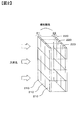
図3は、第1の撮像素子部21の一部である10行×6列の画素210の配置と、第2の撮像素子部22の一部である10行×6列の画素220の配置と、をそれぞれ示す図である。図3(a)において、第1の撮像素子部21について、画素210に付された「Mg」は、その画素がマゼンタの色成分を吸収し光電変換する画素、すなわち、マゼンタの分光感度を有する画素を示し、同様に、画素210に付された「Ye」は、その画素がイエローの色成分を吸収し光電変換する画素、すなわち、イエローの分光感度を有する画素を示し、画素210に付された「Cy」は、その画素がシアンの色成分を吸収し光電変換する画素、すなわち、シアンの分光感度を有する画素を示す。第1の撮像素子部21は、奇数行の画素列では、「Mg」画素210と「Ye」画素210が交互に配列され、偶数行の画素列では、「Cy」画素210と「Mg」画素210とが交互に配列されている。
FIG. 3 shows an arrangement of 10 rows × 6 columns of pixels 210 that are part of the first image sensor unit 21 and an arrangement of pixels 220 of 10 rows × 6 columns that are part of the second image sensor unit 22. FIG. In FIG. 3A, “Mg” attached to the pixel 210 in the first image sensor section 21 has a pixel that absorbs a magenta color component and performs photoelectric conversion, that is, has a spectral sensitivity of magenta. Similarly, “Ye” added to the pixel 210 indicates a pixel that absorbs a yellow color component and photoelectrically converts the pixel, that is, a pixel having a spectral sensitivity of yellow, and is attached to the pixel 210. “Cy” indicates a pixel in which the pixel absorbs a cyan color component and performs photoelectric conversion, that is, a pixel having cyan spectral sensitivity. In the first image sensor unit 21, “Mg” pixels 210 and “Ye” pixels 210 are alternately arranged in odd-numbered pixel columns, and “Cy” pixels 210 and “Mg” pixels in even-numbered pixel columns. 210 are alternately arranged.
図3(b)において、第2の撮像素子部22について、画素220に付された「G」は、その画素が緑の色成分を吸収し光電変換する画素、すなわち、緑の分光感度を有する画素を示し、同様に、画素220に付された「B」は、その画素が青の色成分を吸収し光電変換する画素、すなわち、青の分光感度を有する画素を示し、画素220に付された「R」は、その画素が赤の色成分を吸収し光電変換する画素、すなわち、赤の分光感度を有する画素を示す。第2の撮像素子部22は、奇数行の画素列では、「G」画素220と「B」画素220が交互に配列され、偶数行の画素列では、「R」画素220と「G」画素220とが交互に配列されている。すなわち、第2の撮像素子部22は、画素がベイヤ配列されている。
図3(a)および(b)において、第1の撮像素子部21の「Mg」画素210と第2の撮像素子部22の「G」画素220とは、対応関係にあり、第1の撮像素子部21の「Ye」画素210と第2の撮像素子部22の「B」画素220とは、対応関係にあり、第1の撮像素子部21の「Cy」画素210と第2の撮像素子部22の「R」画素220とは、対応関係にある。 In FIG. 3B, for the secondimage sensor section 22, “G” attached to the pixel 220 has a pixel that absorbs a green color component and photoelectrically converts the pixel, that is, has a green spectral sensitivity. Similarly, “B” attached to the pixel 220 indicates a pixel that absorbs a blue color component and performs photoelectric conversion, that is, a pixel having blue spectral sensitivity, and is attached to the pixel 220. “R” indicates a pixel in which the pixel absorbs a red color component and performs photoelectric conversion, that is, a pixel having red spectral sensitivity. In the second image sensor unit 22, “G” pixels 220 and “B” pixels 220 are alternately arranged in the odd-numbered pixel columns, and “R” pixels 220 and “G” pixels in the even-numbered pixel columns. 220 are alternately arranged. That is, in the second image sensor unit 22, pixels are arranged in a Bayer array.
3A and 3B, the “Mg”pixel 210 of the first image sensor unit 21 and the “G” pixel 220 of the second image sensor unit 22 have a correspondence relationship, and the first image sensor The “Y” pixel 210 of the element unit 21 and the “B” pixel 220 of the second image sensor unit 22 have a correspondence relationship, and the “Cy” pixel 210 of the first image sensor unit 21 and the second image sensor The “R” pixel 220 of the unit 22 has a correspondence relationship.
図3(a)および(b)において、第1の撮像素子部21の「Mg」画素210と第2の撮像素子部22の「G」画素220とは、対応関係にあり、第1の撮像素子部21の「Ye」画素210と第2の撮像素子部22の「B」画素220とは、対応関係にあり、第1の撮像素子部21の「Cy」画素210と第2の撮像素子部22の「R」画素220とは、対応関係にある。 In FIG. 3B, for the second
3A and 3B, the “Mg”
このように、有機光電変換膜で構成される第1の撮像素子部21が第2の撮像素子部22に対してカラーフィルターの役割を果たし、第2の撮像素子部22から第1の撮像素子部21の補色画像(図3の例ではベイヤ配列の画像)が得られる。したがって、第1の撮像素子部21からはCy,Mg,Yeの3色からなるCMY画像を取得することができ、第2の撮像素子部22からはR,G,Bの3色からなるRGB画像を取得することができる。なお、第1の撮像素子部21から取得されるCMY画像は、図1に示した画像処理部14で公知の表色系変換処理によってRGB画像に変換される。
Thus, the 1st image sensor part 21 comprised with an organic photoelectric conversion film plays the role of a color filter with respect to the 2nd image sensor part 22, and the 1st image sensor from the 2nd image sensor part 22 A complementary color image (bayer array image in the example of FIG. 3) of the unit 21 is obtained. Therefore, a CMY image composed of three colors Cy, Mg, and Ye can be acquired from the first image sensor section 21, and an RGB composed of three colors R, G, and B can be obtained from the second image sensor section 22. Images can be acquired. The CMY image acquired from the first image sensor unit 21 is converted into an RGB image by a known color system conversion process by the image processing unit 14 shown in FIG.
図4(a)~(c)は、第1の撮像素子部21の画素210の構造を模式的に示す図である。図4(a)は、第1の撮像素子部21の1つの画素210を被写体側から見た図であり、図4(b)は、画素210を被写体側とは反対側から見た図であり、図4(c)は、図4(a)のc1-c1矢視断面図である。第1の撮像素子部21の各画素210は、マゼンタの色成分、イエローの色成分、またはシアンの色成分を吸収する有機光電変換膜230と、有機光電変換膜230の上面、すなわち有機光電変換膜230の被写体側の面に形成された透明な共通電極231と、有機光電変換膜230の下面に形成された透明な部分電極232とを有する。部分電極232は、第1乃至第3の部分電極232a,232b,232cを有する。なお、共通電極231を上部電極層とも呼び、第1乃至第3の部分電極232a,232b,232cを下部電極層とも呼ぶ。また、有機光電変換膜230を光電変換層とも呼ぶ。
FIGS. 4A to 4C are diagrams schematically showing the structure of the pixel 210 of the first image sensor section 21. FIG. 4A is a view of one pixel 210 of the first image sensor section 21 as viewed from the subject side, and FIG. 4B is a view of the pixel 210 as viewed from the opposite side to the subject side. FIG. 4C is a cross-sectional view taken along the line c1-c1 in FIG. Each pixel 210 of the first image sensor unit 21 includes an organic photoelectric conversion film 230 that absorbs a magenta color component, a yellow color component, or a cyan color component, and an upper surface of the organic photoelectric conversion film 230, that is, organic photoelectric conversion. The transparent common electrode 231 formed on the subject side surface of the film 230 and the transparent partial electrode 232 formed on the lower surface of the organic photoelectric conversion film 230 are included. The partial electrode 232 includes first to third partial electrodes 232a, 232b, and 232c. The common electrode 231 is also referred to as an upper electrode layer, and the first to third partial electrodes 232a, 232b, and 232c are also referred to as lower electrode layers. The organic photoelectric conversion film 230 is also referred to as a photoelectric conversion layer.
図4(b)に示すように、第1の部分電極232aは、円形の電極であり、画素210の中心に配置されている。第2の部分電極232bは、第1の部分電極232aの全周囲を取り囲む円環状の電極である。第3の部分電極232cは、第2の部分電極232bの全周囲を取り囲む円環状の電極である。すなわち、第2の部分電極232bの外径d2は、第1の部分電極232aの外径d1よりも大きく、第3の部分電極232cの外径d3は、第2の部分電極232bの外径d2よりも大きい。
このように構成された画素210では、後述するように、有機光電変換膜230から電荷を読み出す領域を、第1乃至第3の部分電極232a~232cの組合せによって選択することができる。
共通電極231は、第1の撮像素子部21の全ての画素210に関して共通の電極とすることもできるし、画素210毎に共通とすることもできる。すなわち、共通電極231は、全ての画素210に関して共通とすることも、各画素の部分電極232a~232cに対して共通とすることもできる。 As shown in FIG. 4B, the firstpartial electrode 232 a is a circular electrode and is arranged at the center of the pixel 210. The second partial electrode 232b is an annular electrode that surrounds the entire periphery of the first partial electrode 232a. The third partial electrode 232c is an annular electrode that surrounds the entire periphery of the second partial electrode 232b. That is, the outer diameter d2 of the second partial electrode 232b is larger than the outer diameter d1 of the first partial electrode 232a, and the outer diameter d3 of the third partial electrode 232c is the outer diameter d2 of the second partial electrode 232b. Bigger than.
In thepixel 210 configured as described above, as will be described later, a region for reading out charges from the organic photoelectric conversion film 230 can be selected by a combination of the first to third partial electrodes 232a to 232c.
Thecommon electrode 231 can be a common electrode for all the pixels 210 of the first image sensor unit 21 or can be common to each pixel 210. That is, the common electrode 231 can be common to all the pixels 210 or can be common to the partial electrodes 232a to 232c of each pixel.
このように構成された画素210では、後述するように、有機光電変換膜230から電荷を読み出す領域を、第1乃至第3の部分電極232a~232cの組合せによって選択することができる。
共通電極231は、第1の撮像素子部21の全ての画素210に関して共通の電極とすることもできるし、画素210毎に共通とすることもできる。すなわち、共通電極231は、全ての画素210に関して共通とすることも、各画素の部分電極232a~232cに対して共通とすることもできる。 As shown in FIG. 4B, the first
In the
The
図5は、第2の撮像素子部22の画素220の構造を模式的に示す図であり、第2の撮像素子部22の1つの画素220を被写体側から見た図である。画素220は、円形の光電変換部220aを有する。光電変換部220aの外径は、第1の撮像素子部21の画素210の第3の部分電極232cの外径d3と等しい。なお、光電変換部220aは、撮影光学系10の絞りの開放F値の瞳領域の全領域を通過した光束を受光する。
FIG. 5 is a diagram schematically showing the structure of the pixel 220 of the second image sensor section 22, and is a view of one pixel 220 of the second image sensor section 22 as viewed from the subject side. The pixel 220 includes a circular photoelectric conversion unit 220a. The outer diameter of the photoelectric conversion unit 220a is equal to the outer diameter d3 of the third partial electrode 232c of the pixel 210 of the first imaging element unit 21. The photoelectric conversion unit 220a receives the light beam that has passed through the entire pupil area of the aperture F value of the stop of the photographing optical system 10.
図6は、第1および第2の撮像素子部21,22の一画素210,220の構成を示す断面図である。図6に示すように、第2の撮像素子部22は、半導体基板50に形成され、各画素220は、光電変換部220aを有する。第2の撮像素子部22の表面、すなわち、上面には平坦化層55を介して第1の撮像素子部21が積層されている。この平坦化層55内には、不図示の配線層が形成されている。
また、第1の撮像素子部21の各画素210の上方には、それぞれマイクロレンズ233が配置され、各マイクロレンズ233と第1の撮像素子部21の各画素210と第2の撮像素子部22の各画素220とはマイクロレンズ233の光軸方向に、整列配置されている。 FIG. 6 is a cross-sectional view showing the configuration of the pixels 210 and 220 of the first and second image sensor sections 21 and 22. As illustrated in FIG. 6, the second imaging element unit 22 is formed on the semiconductor substrate 50, and each pixel 220 includes a photoelectric conversion unit 220 a. The first imaging element unit 21 is stacked on the surface of the second imaging element unit 22, that is, the upper surface, with the planarizing layer 55 interposed therebetween. A wiring layer (not shown) is formed in the flattening layer 55.
In addition, amicrolens 233 is disposed above each pixel 210 of the first image sensor unit 21, and each microlens 233, each pixel 210 of the first image sensor unit 21, and the second image sensor unit 22. These pixels 220 are aligned in the optical axis direction of the microlens 233.
また、第1の撮像素子部21の各画素210の上方には、それぞれマイクロレンズ233が配置され、各マイクロレンズ233と第1の撮像素子部21の各画素210と第2の撮像素子部22の各画素220とはマイクロレンズ233の光軸方向に、整列配置されている。 FIG. 6 is a cross-sectional view showing the configuration of the
In addition, a
図7は、第1の撮像素子部21における1つの画素210の信号読み出し回路構成を例示する図である。各画素210の信号読み出し回路は、電極選択トランジスタ301,302と、リセットトランジスタ303と、出力トランジスタ304と、行選択トランジスタ305とを有する。共通電極231は、グラウンドに接続されている。第1の部分電極232aは出力トランジスタ304のゲートに接続されている。第2の部分電極232bと出力トランジスタ303のゲートとは電極選択トランジスタ301を介して接続され、第3の部分電極232cと出力トランジスタ304のゲートとは電極選択トランジスタ302を介して接続される。
FIG. 7 is a diagram illustrating a signal readout circuit configuration of one pixel 210 in the first image sensor section 21. The signal readout circuit of each pixel 210 includes electrode selection transistors 301 and 302, a reset transistor 303, an output transistor 304, and a row selection transistor 305. The common electrode 231 is connected to the ground. The first partial electrode 232 a is connected to the gate of the output transistor 304. The second partial electrode 232 b and the gate of the output transistor 303 are connected via an electrode selection transistor 301, and the third partial electrode 232 c and the gate of the output transistor 304 are connected via an electrode selection transistor 302.
出力トランジスタ304は、第1の部分電極232aからの電荷に基づく電圧信号を増幅する。また、電極選択トランジスタ301がオンされる、すなわち導通状態にされると、第2の部分電極232bからの電荷が第1の部分電極232aからの電荷に加算され、出力トランジスタ304は、この加算された電荷に基づく電圧信号を増幅する。電極選択トランジスタ301および302が共にオンされると、第2の部分電極232bからの電荷と第3の部分電極231cからの電荷とが第1の部分電極232aからの電荷に加算され、出力トランジスタ304は、この加算電荷に基づく電圧信号を増幅する。また、電極選択トランジスタ301がオフで電極選択トランジスタ302がオンされると、第3の部分電極231cからの電荷が第1の部分電極232aからの電荷に加算され、出力トランジスタ304は、この加算電荷に基づく電圧信号を増幅する。
The output transistor 304 amplifies the voltage signal based on the charge from the first partial electrode 232a. Further, when the electrode selection transistor 301 is turned on, that is, in a conductive state, the charge from the second partial electrode 232b is added to the charge from the first partial electrode 232a, and the output transistor 304 is added. Amplifies the voltage signal based on the generated charge. When the electrode selection transistors 301 and 302 are both turned on, the charge from the second partial electrode 232b and the charge from the third partial electrode 231c are added to the charge from the first partial electrode 232a, and the output transistor 304 Amplifies the voltage signal based on this added charge. When the electrode selection transistor 301 is turned off and the electrode selection transistor 302 is turned on, the charge from the third partial electrode 231c is added to the charge from the first partial electrode 232a, and the output transistor 304 Amplifies the voltage signal based on
出力トランジスタ304で増幅された信号は、行選択トランジスタ305を介して端子Voutから読み出される。リセットトランジスタ303は、リセット信号φRSTに応じて不要電荷を排出させる(すなわち所定電位にリセットする)。
なお、第2の撮像素子部22における1つの画素220の信号読み出し回路構成は公知であるので、説明を省略する。 The signal amplified by theoutput transistor 304 is read from the terminal Vout through the row selection transistor 305. The reset transistor 303 discharges unnecessary charges in response to the reset signal φRST (that is, resets to a predetermined potential).
Note that the signal readout circuit configuration of onepixel 220 in the second imaging element unit 22 is well known, and thus description thereof is omitted.
なお、第2の撮像素子部22における1つの画素220の信号読み出し回路構成は公知であるので、説明を省略する。 The signal amplified by the
Note that the signal readout circuit configuration of one
---画素210から電荷を読み出す領域について---
図8を参照して、電極選択トランジスタ301,302のオンオフ状態に応じて、画素210の有機光電変換膜230に、複数の光電変換領域を形成する例を説明する。図8(a)~(c)は、被写体側から見た、画素210の有機光電変換膜230において電荷を読み出す光電変換領域を示す図である。第1の撮像素子部21では、以下に説明するように、有機光電変換膜230で発生した電荷を読み出すことができる光電変換領域は、共通電極231と第1乃至第3の部分電極232a~232cとで挟まれた領域のうち、共通電極231と読み出しに用いられる部分電極とが重なり合う領域である。 --- Regarding the region for reading out charges from thepixel 210--
With reference to FIG. 8, an example in which a plurality of photoelectric conversion regions are formed in the organicphotoelectric conversion film 230 of the pixel 210 in accordance with the on / off state of the electrode selection transistors 301 and 302 will be described. FIGS. 8A to 8C are diagrams showing a photoelectric conversion region for reading out charges from the organic photoelectric conversion film 230 of the pixel 210 as viewed from the subject side. As will be described below, in the first imaging element unit 21, the photoelectric conversion regions from which the charges generated in the organic photoelectric conversion film 230 can be read are the common electrode 231 and the first to third partial electrodes 232a to 232c. Is an area where the common electrode 231 and the partial electrode used for reading overlap.
図8を参照して、電極選択トランジスタ301,302のオンオフ状態に応じて、画素210の有機光電変換膜230に、複数の光電変換領域を形成する例を説明する。図8(a)~(c)は、被写体側から見た、画素210の有機光電変換膜230において電荷を読み出す光電変換領域を示す図である。第1の撮像素子部21では、以下に説明するように、有機光電変換膜230で発生した電荷を読み出すことができる光電変換領域は、共通電極231と第1乃至第3の部分電極232a~232cとで挟まれた領域のうち、共通電極231と読み出しに用いられる部分電極とが重なり合う領域である。 --- Regarding the region for reading out charges from the
With reference to FIG. 8, an example in which a plurality of photoelectric conversion regions are formed in the organic
(1)図8(a)に示した電荷読み出し領域のパターンについて
図8(a)は、第1乃至第3の光電変換領域251~253を有機光電変換膜230に形成する例である。第1の光電変換領域251は、第1の部分電極232aがカバーする(すなわち、被う)有機光電変換膜230の領域に対応し、第2の光電変換領域252は、第2の部分電極232bがカバーする有機光電変換膜230の領域に対応し、第3の光電変換領域253は、第3の部分電極232cがカバーする有機光電変換膜230の領域に対応する。この第1乃至第3の光電変換領域251~253からの加算された電荷に基づく光電変換信号を読み出すためには、制御信号ΦP1,ΦP2によって電極選択トランジスタ301,302をオンにする。 (1) Regarding the pattern of the charge readout region shown in FIG. 8A FIG. 8A shows an example in which the first to thirdphotoelectric conversion regions 251 to 253 are formed in the organic photoelectric conversion film 230. The first photoelectric conversion region 251 corresponds to the region of the organic photoelectric conversion film 230 that is covered (that is, covered) by the first partial electrode 232a, and the second photoelectric conversion region 252 is the second partial electrode 232b. Corresponds to the region of the organic photoelectric conversion film 230 covered by the third photoelectric conversion region 253, and the third photoelectric conversion region 253 corresponds to the region of the organic photoelectric conversion film 230 covered by the third partial electrode 232c. In order to read out photoelectric conversion signals based on the added charges from the first to third photoelectric conversion regions 251 to 253, the electrode selection transistors 301 and 302 are turned on by the control signals ΦP1 and ΦP2.
図8(a)は、第1乃至第3の光電変換領域251~253を有機光電変換膜230に形成する例である。第1の光電変換領域251は、第1の部分電極232aがカバーする(すなわち、被う)有機光電変換膜230の領域に対応し、第2の光電変換領域252は、第2の部分電極232bがカバーする有機光電変換膜230の領域に対応し、第3の光電変換領域253は、第3の部分電極232cがカバーする有機光電変換膜230の領域に対応する。この第1乃至第3の光電変換領域251~253からの加算された電荷に基づく光電変換信号を読み出すためには、制御信号ΦP1,ΦP2によって電極選択トランジスタ301,302をオンにする。 (1) Regarding the pattern of the charge readout region shown in FIG. 8A FIG. 8A shows an example in which the first to third
制御信号ΦP1,ΦP2によって電極選択トランジスタ301,302がオンされると、上述したように、有機光電変換膜230において、共通電極231と第1の部分電極232aとの重複領域で発生した電荷と、共通電極231と第2の部分電極232bとの重複領域で発生した電荷と、共通電極231と第3の部分電極232cとの重複領域で発生した電荷とが加算された加算電荷が出力トランジスタ304のゲートに出力される。したがって、図8(a)でハッチングを施した第1乃至第3の光電変換領域251~253で発生した加算電荷に基づく光電変換信号が端子Voutから読み出される。図1の画像処理部14は、この読み出された光電変換信号に基づき画像データを生成する。
なお、この画像データは、撮影光学系10の絞りが開放F値である場合の画像である。 When the electrode selection transistors 301 and 302 are turned on by the control signals ΦP1 and ΦP2, as described above, in the organic photoelectric conversion film 230, the charge generated in the overlapping region between the common electrode 231 and the first partial electrode 232a, An added charge obtained by adding the charge generated in the overlapping region between the common electrode 231 and the second partial electrode 232b and the charge generated in the overlapping region between the common electrode 231 and the third partial electrode 232c is output from the output transistor 304. Output to the gate. Therefore, photoelectric conversion signals based on the added charges generated in the first to third photoelectric conversion regions 251 to 253 hatched in FIG. 8A are read from the terminal Vout. The image processing unit 14 in FIG. 1 generates image data based on the read photoelectric conversion signal.
The image data is an image when the aperture of the photographingoptical system 10 has an open F value.
なお、この画像データは、撮影光学系10の絞りが開放F値である場合の画像である。 When the
The image data is an image when the aperture of the photographing
なお、第1の光電変換領域251で発生した電荷に基づく光電変換信号を、第1の部分電極232aに基づく光電変換信号とも呼び、第2の光電変換領域252で発生した電荷に基づく光電変換信号を、第2の部分電極232bに基づく光電変換信号とも呼び、第3の光電変換領域253で発生した電荷に基づく光電変換信号を、第3の部分電極232cに基づく光電変換信号とも呼ぶ。
Note that the photoelectric conversion signal based on the charge generated in the first photoelectric conversion region 251 is also referred to as a photoelectric conversion signal based on the first partial electrode 232a, and the photoelectric conversion signal based on the charge generated in the second photoelectric conversion region 252. Is also referred to as a photoelectric conversion signal based on the second partial electrode 232b, and a photoelectric conversion signal based on the charge generated in the third photoelectric conversion region 253 is also referred to as a photoelectric conversion signal based on the third partial electrode 232c.
(2)図8(b)に示した電荷読み出し領域のパターンについて
図8(b)は、第1および第2の光電変換領域251,252を有機光電変換膜230に形成する例である。第1および第2の光電変換領域251,252からの光電変換信号を読み出すためには、制御信号ΦP1によって電極選択トランジスタ301をオンにする。 (2) Regarding the pattern of the charge readout region shown in FIG. 8B FIG. 8B shows an example in which the first and second photoelectric conversion regions 251 and 252 are formed in the organic photoelectric conversion film 230. In order to read out the photoelectric conversion signals from the first and second photoelectric conversion regions 251 and 252, the electrode selection transistor 301 is turned on by the control signal ΦP 1.
図8(b)は、第1および第2の光電変換領域251,252を有機光電変換膜230に形成する例である。第1および第2の光電変換領域251,252からの光電変換信号を読み出すためには、制御信号ΦP1によって電極選択トランジスタ301をオンにする。 (2) Regarding the pattern of the charge readout region shown in FIG. 8B FIG. 8B shows an example in which the first and second
制御信号ΦP1によって電極選択トランジスタ301がオンされ、信号ΦP2によって電極選択トランジスタ302がオフされると、上述したように、有機光電変換膜230において共通電極231と、第1および第2の部分電極232a,232bとのそれぞれの重複領域で発生した電荷の加算電荷が出力トランジスタ304のゲートに出力される。したがって、図8(b)でハッチングを施した第1および第2の光電変換領域251,252で発生した加算電荷に基づく光電変換信号が端子Voutから読み出される。図1の画像処理部14は、この読み出された光電変換信号に基づき画像データを生成する。
なお、この画像データは、撮影光学系10の絞りが開放F値から所定の第1のF値まで絞り込まれた場合の画像である。 When theelectrode selection transistor 301 is turned on by the control signal ΦP1 and the electrode selection transistor 302 is turned off by the signal ΦP2, as described above, in the organic photoelectric conversion film 230, the common electrode 231 and the first and second partial electrodes 232a. , 232b, the added charge generated in each overlapping region is output to the gate of the output transistor 304. Therefore, a photoelectric conversion signal based on the added charge generated in the first and second photoelectric conversion regions 251 and 252 that are hatched in FIG. 8B is read from the terminal Vout. The image processing unit 14 in FIG. 1 generates image data based on the read photoelectric conversion signal.
This image data is an image when the aperture of the photographingoptical system 10 is reduced from the open F value to a predetermined first F value.
なお、この画像データは、撮影光学系10の絞りが開放F値から所定の第1のF値まで絞り込まれた場合の画像である。 When the
This image data is an image when the aperture of the photographing
(3)図8(c)に示した電荷読み出し領域のパターンについて
図8(c)は、第1の光電変換領域251を有機光電変換膜230に形成する例である。第1の光電変換領域251からの電荷に基づく光電変換信号を読み出すためには、電極選択トランジスタ301,302をオフしたままにする。 (3) Regarding the pattern of the charge readout region shown in FIG. 8C FIG. 8C shows an example in which the firstphotoelectric conversion region 251 is formed in the organic photoelectric conversion film 230. In order to read out a photoelectric conversion signal based on the charge from the first photoelectric conversion region 251, the electrode selection transistors 301 and 302 are kept off.
図8(c)は、第1の光電変換領域251を有機光電変換膜230に形成する例である。第1の光電変換領域251からの電荷に基づく光電変換信号を読み出すためには、電極選択トランジスタ301,302をオフしたままにする。 (3) Regarding the pattern of the charge readout region shown in FIG. 8C FIG. 8C shows an example in which the first
電極選択トランジスタ301,302を共にオフにすると、上述したように、有機光電変換膜230における共通電極231と、第1の部分電極232aとの重複領域で発生した電荷が出力トランジスタ304のゲートに出力される。したがって、図8(c)でハッチングを施した第1の光電変換領域251で発生した電荷に基づく光電変換信号が端子Voutから読み出される。図1の画像処理部14は、この読み出された光電変換信号に基づき画像データを生成する。
なお、この画像データは、撮影光学系10の絞りが第1のF値からさらに第2のF値まで絞り込まれた場合の画像である。 When the electrode selection transistors 301 and 302 are both turned off, as described above, the charge generated in the overlapping region between the common electrode 231 and the first partial electrode 232a in the organic photoelectric conversion film 230 is output to the gate of the output transistor 304. Is done. Therefore, a photoelectric conversion signal based on the charge generated in the first photoelectric conversion region 251 hatched in FIG. 8C is read from the terminal Vout. The image processing unit 14 in FIG. 1 generates image data based on the read photoelectric conversion signal.
This image data is an image when the aperture of the photographingoptical system 10 is further reduced from the first F value to the second F value.
なお、この画像データは、撮影光学系10の絞りが第1のF値からさらに第2のF値まで絞り込まれた場合の画像である。 When the
This image data is an image when the aperture of the photographing
図8(a)の光電変換領域から得られる開放F値に対応した画像データと、図8(b)の光電変換領域から得られる第1のF値に対応する画像データと、図8(c)の光電変換領域から得られる第2のF値に対応する画像データとを比べると、開放F値に対応した画像データは、相対的に浅い又は小さい焦点深度(被写界深度)の画像であり、第1のF値に対応する画像データは、相対的に中位の焦点深度(被写界深度)の画像であり、第2のF値に対応する画像データは、相対的に大きい焦点深度(被写界深度)の画像である。
Image data corresponding to the open F value obtained from the photoelectric conversion region in FIG. 8A, image data corresponding to the first F value obtained from the photoelectric conversion region in FIG. 8B, and FIG. ) Image data corresponding to the second F value obtained from the photoelectric conversion region in FIG. 5B, the image data corresponding to the open F value is an image having a relatively shallow or small depth of focus (depth of field). Yes, the image data corresponding to the first F value is an image having a relatively medium depth of focus (depth of field), and the image data corresponding to the second F value is a relatively large focus. It is an image of depth (depth of field).
他方、上述したように、第2の撮像素子部22の各画素220は、撮影光学系10の絞りの開放F値の瞳領域の全領域を通過した光束を受光する光電変換部220aを有し、図1の画像処理部14で各画素220から読み出された光電変換信号に基づき画像データを生成する。
なお、第1の撮像素子部21の各画素210を透過して第2の撮像素子22の対応する画素220に入射する光量は、図8(a)~(c)に示した画素210の電荷読み出しのパターンに無関係であり、同一となる。したがって、第2の撮像素子22の各画素220から読み出された光電変換信号に基づく画像データは、撮影光学系10の絞りが開放F値である場合の画像である。この第2の撮像素子部22による開放F値に対応した画像データは、焦点深度(被写界深度)が相対的に浅い又は小さい画像である。 On the other hand, as described above, eachpixel 220 of the second imaging element unit 22 includes the photoelectric conversion unit 220a that receives the light beam that has passed through the entire pupil region of the aperture F value of the aperture of the photographing optical system 10. The image processing unit 14 in FIG. 1 generates image data based on the photoelectric conversion signal read from each pixel 220.
Note that the amount of light that passes through eachpixel 210 of the first image sensor unit 21 and enters the corresponding pixel 220 of the second image sensor 22 is the charge of the pixel 210 shown in FIGS. 8A to 8C. It is irrelevant to the read pattern and is the same. Accordingly, the image data based on the photoelectric conversion signal read from each pixel 220 of the second image sensor 22 is an image when the aperture of the photographing optical system 10 has an open F value. The image data corresponding to the open F value by the second image sensor unit 22 is an image having a relatively shallow depth of focus (depth of field).
なお、第1の撮像素子部21の各画素210を透過して第2の撮像素子22の対応する画素220に入射する光量は、図8(a)~(c)に示した画素210の電荷読み出しのパターンに無関係であり、同一となる。したがって、第2の撮像素子22の各画素220から読み出された光電変換信号に基づく画像データは、撮影光学系10の絞りが開放F値である場合の画像である。この第2の撮像素子部22による開放F値に対応した画像データは、焦点深度(被写界深度)が相対的に浅い又は小さい画像である。 On the other hand, as described above, each
Note that the amount of light that passes through each
次に、デジタルカメラ1が一回の撮影動作によって、焦点深度(被写界深度)の異なった画像データを生成する方法を説明する。図1に示した操作部13が複数焦点深度(被写界深度)撮影モードの内の大焦点深度(被写界深度)撮影モードを選択設定すると、撮影光学系10の絞りが開放F値に設定され、電極選択トランジスタ301,302が共にオフ状態にされる。第1および第2の撮像素子部21,22は、同時に撮影動作、すなわち露光動作が開始される。第1の撮像素子部21の各画素210は、図8(c)に示した第1の光電変換領域251で発生した電荷に基づく光電変換信号が読み出され、図1の画像処理部14は、この読み出された光電変換信号に対して画像処理を施して、撮影光学系10の絞りが第2のF値である場合の画像データを生成する。なお、画像処理部14は、第1の撮像素子部21からの光電変換信号に対する画像処理の際には、CMY画像データを表色系変換処理によってRGB画像データに変換する。
Next, a method in which the digital camera 1 generates image data having different depths of focus (depth of field) by one shooting operation will be described. When the operation unit 13 illustrated in FIG. 1 selects and sets a large focal depth (depth of field) photographing mode among the multiple focal depth (depth of field) photographing modes, the aperture of the photographing optical system 10 is set to an open F value. Thus, both the electrode selection transistors 301 and 302 are turned off. The first and second image sensor units 21 and 22 start a photographing operation, that is, an exposure operation at the same time. Each pixel 210 of the first image sensor section 21 reads a photoelectric conversion signal based on the charge generated in the first photoelectric conversion area 251 shown in FIG. 8C, and the image processing section 14 in FIG. Then, image processing is performed on the read photoelectric conversion signal to generate image data when the aperture of the photographing optical system 10 has the second F value. Note that the image processing unit 14 converts CMY image data into RGB image data by color system conversion processing when performing image processing on the photoelectric conversion signal from the first image sensor unit 21.
これと同時に、第2の撮像素子部22の各画素220は、光電変換部220aによる光電変換信号が読み出され、図1の画像処理部14は、この読み出された光電変換信号に基づき、撮影光学系10の絞りが開放F値である場合のRGB画像データを生成する。
第2のF値に対応する画像データと開放F値に対応する画像データとは、必要に応じて液晶モニタ15にそれぞれ、表示されると共に、メモリカード17に記録される。
また、第2のF値に対応する画像データと開放F値に対応する画像データは、図1の画像合成部12bによって画像合成され、合成画像が生成され、この合成画像も必要に応じて液晶モニタ15に表示されると共に、メモリカード17に記録される。 At the same time, eachpixel 220 of the second image sensor unit 22 reads a photoelectric conversion signal from the photoelectric conversion unit 220a, and the image processing unit 14 in FIG. 1 reads the photoelectric conversion signal based on the read photoelectric conversion signal. RGB image data when the aperture of the photographing optical system 10 has an open F value is generated.
The image data corresponding to the second F value and the image data corresponding to the open F value are displayed on the liquid crystal monitor 15 and recorded on thememory card 17 as necessary.
In addition, the image data corresponding to the second F value and the image data corresponding to the open F value are combined by theimage combining unit 12b in FIG. 1 to generate a combined image. It is displayed on the monitor 15 and recorded on the memory card 17.
第2のF値に対応する画像データと開放F値に対応する画像データとは、必要に応じて液晶モニタ15にそれぞれ、表示されると共に、メモリカード17に記録される。
また、第2のF値に対応する画像データと開放F値に対応する画像データは、図1の画像合成部12bによって画像合成され、合成画像が生成され、この合成画像も必要に応じて液晶モニタ15に表示されると共に、メモリカード17に記録される。 At the same time, each
The image data corresponding to the second F value and the image data corresponding to the open F value are displayed on the liquid crystal monitor 15 and recorded on the
In addition, the image data corresponding to the second F value and the image data corresponding to the open F value are combined by the
上述のように、開放F値に対応する画像データは、焦点深度(被写界深度)が小さく、他方、第2のF値に対応する画像データは、焦点深度(被写界深度)が大きい。したがって、開放F値に対応する画像データは、たとえば、近景(至近距離の)主要被写体像にはピントが合っているが、遠景および中景の背景像にはピントが合っておらずボケが生じた画像であったり、たとえば、中景被写体像にはピントが合っているが、近景および遠景の被写体像にはピントが合っておらずボケた画像であったり、または、遠景被写体像にはピントが合っているが、近景および中景被写体像にはピントが合っておらずボケた画像となる。他方、第2のF値に対応する画像データは、たとえば、近景、中景、および遠景の全ての被写体像にピントが合った画像となる。
As described above, the image data corresponding to the open F value has a small depth of focus (depth of field), while the image data corresponding to the second F value has a large depth of focus (depth of field). . Therefore, the image data corresponding to the open F value, for example, is focused on the main subject image in the foreground (closest distance), but is not in focus on the background image of the distant view and the middle background, and blur occurs. For example, a mid-range subject image is in focus, but a foreground or distant subject image is out of focus, or a distant subject image is in focus. However, the foreground and middle-ground subject images are out of focus and are out of focus. On the other hand, the image data corresponding to the second F value is, for example, an image in which all the subject images in the near view, the middle view, and the distant view are in focus.
また、図1の画像合成部12bによって画像合成された合成画像データは、たとえば、開放F値に対応する画像データからボケた中景被写体像の画像データを抽出し、第2のF値に対応する画像データからピントの合った近景および遠景の被写体像の画像データを抽出し、抽出した画像を合成すると、近景および遠景の被写体像にピントが合い、中景の被写体像にボケが生じた画像データとなる。このように、焦点深度の浅い開放F値に対応する画像データと焦点深度の深い第2のF値に対応する画像データとを合成することによって、通常の撮影光学系からは、得ることができない合成画像データを得ることもできる。
Further, the composite image data synthesized by the image composition unit 12b in FIG. 1 extracts, for example, image data of a blurred background image from image data corresponding to the open F value, and corresponds to the second F value. When the image data of the subject in the near view and the distant view that are in focus is extracted from the image data that is in focus, and the extracted images are combined, the subject image in the foreground and the distant view is in focus and the image in which the subject image in the foreground is blurred It becomes data. As described above, the image data corresponding to the open F value having a shallow focal depth and the image data corresponding to the second F value having a deep focal depth cannot be obtained from a normal photographing optical system. Composite image data can also be obtained.
図1に示した操作部13が複数焦点深度(被写界深度)撮影モードの内の中位の焦点深度(被写界深度)撮影モードを選択設定すると、撮影光学系10の絞りが開放F値に設定され、電極選択トランジスタ301がオンされ、かつ電極選択トランジスタ302がオフにされ、第1の撮像素子部21の各画素210は、図8(b)に示した第1および第2の光電変換領域251、252で発生した電荷に基づく光電変換信号が読み出され、図1の画像処理部14は、この読み出された光電変換信号に対して、前述の表色系変換処理を含む画像処理を施して、撮影光学系10の絞りが第1のF値である場合のRGB画像データを生成する。
When the operation unit 13 shown in FIG. 1 selects and sets a middle depth of focus (depth of field) shooting mode in the multiple depth of focus (depth of field) shooting mode, the aperture of the shooting optical system 10 is opened F. Is set to a value, the electrode selection transistor 301 is turned on, and the electrode selection transistor 302 is turned off, so that each pixel 210 of the first image sensor section 21 has the first and second pixels shown in FIG. A photoelectric conversion signal based on the charges generated in the photoelectric conversion regions 251 and 252 is read, and the image processing unit 14 in FIG. 1 includes the above-described color system conversion processing for the read photoelectric conversion signal. Image processing is performed to generate RGB image data when the aperture of the photographing optical system 10 has the first F value.
これと同時に、第2の撮像素子部22の各画素220は、光電変換部220aによる光電変換信号が読み出され、図1の画像処理部14は、この読み出された光電変換信号に基づき、撮影光学系10の絞りが開放F値である場合のRGB画像データを生成する。
第1のF値に対応する画像データと開放F値に対応する画像データとは、必要に応じて液晶モニタ15にそれぞれ、表示されると共に、メモリカード17に記録される。
また、第1のF値に対応する画像データと開放F値に対応する画像データは、図1の画像合成部12bによって画像合成され、合成画像が生成され、この合成画像も必要に応じて液晶モニタ15に表示されると共に、メモリカード17に記録される。 At the same time, eachpixel 220 of the second image sensor unit 22 reads a photoelectric conversion signal from the photoelectric conversion unit 220a, and the image processing unit 14 in FIG. 1 reads the photoelectric conversion signal based on the read photoelectric conversion signal. RGB image data when the aperture of the photographing optical system 10 has an open F value is generated.
The image data corresponding to the first F value and the image data corresponding to the open F value are displayed on the liquid crystal monitor 15 and recorded on thememory card 17 as necessary.
Further, the image data corresponding to the first F value and the image data corresponding to the open F value are combined by theimage combining unit 12b in FIG. 1, and a combined image is generated. It is displayed on the monitor 15 and recorded on the memory card 17.
第1のF値に対応する画像データと開放F値に対応する画像データとは、必要に応じて液晶モニタ15にそれぞれ、表示されると共に、メモリカード17に記録される。
また、第1のF値に対応する画像データと開放F値に対応する画像データは、図1の画像合成部12bによって画像合成され、合成画像が生成され、この合成画像も必要に応じて液晶モニタ15に表示されると共に、メモリカード17に記録される。 At the same time, each
The image data corresponding to the first F value and the image data corresponding to the open F value are displayed on the liquid crystal monitor 15 and recorded on the
Further, the image data corresponding to the first F value and the image data corresponding to the open F value are combined by the
なお、第1の撮像素子21の第1のF値に対応する画像データは、相対的に中位の焦点深度(被写界深度)を有するので、たとえば、近景および中景の被写体像にピントが合っているが、遠景被写体像がボケた画像であったり、中景および遠景被写体像にピントが合っているが、近景被写体像がボケた画像である。このような第1のF値に対応する画像データと開放F値に対応する画像データとを合成することによって、種々の合成画像を得ることができ、特に、通常の撮影光学系からは得ることができないような合成画像を得ることができる。
Note that the image data corresponding to the first F value of the first image sensor 21 has a relatively medium depth of focus (depth of field). The distant subject image is out of focus, or the middle and distant subject images are in focus but the foreground subject image is out of focus. By synthesizing the image data corresponding to the first F value and the image data corresponding to the open F value, various composite images can be obtained, and in particular, obtained from a normal photographing optical system. It is possible to obtain a composite image that cannot be performed.
図1に示した操作部13が複数焦点深度(被写界深度)撮影モードの内の小焦点深度(被写界深度)撮影モードを選択設定すると、撮影光学系10の絞りが開放F値に設定され、電極選択トランジスタ301、302が共にオンされ、第1の撮像素子部21の各画素210は、図8(a)に示した第1、第2、および第3の光電変換領域251、252、253で発生した電荷に基づく光電変換信号が読み出され、図1の画像処理部14は、この読み出された光電変換信号に対して、前述の表色系変換処理を含む画像処理を施して、撮影光学系10の絞りが開放F値である場合のRGB画像データを生成する。
When the operation unit 13 shown in FIG. 1 selects and sets a small focus depth (depth of field) shooting mode in the multiple focus depth (depth of field) shooting mode, the aperture of the shooting optical system 10 is set to an open F value. The electrode selection transistors 301 and 302 are both turned on, and each pixel 210 of the first image sensor section 21 has the first, second, and third photoelectric conversion regions 251 illustrated in FIG. The photoelectric conversion signals based on the charges generated in 252 and 253 are read, and the image processing unit 14 in FIG. 1 performs image processing including the above-described color system conversion processing on the read photoelectric conversion signals. Thus, RGB image data is generated when the aperture of the photographing optical system 10 has an open F value.
これと同時に、第2の撮像素子部22の各画素220は、光電変換部220aによる光電変換信号が読み出され、図1の画像処理部14は、この読み出された光電変換信号に基づき、撮影光学系10の絞りが開放F値である場合のRGB画像データを生成する。
第1および第2の撮像素子部21、22による開放F値に対応する画像データは、必要に応じて液晶モニタ15にそれぞれ表示されると共に、メモリカード17に記録される。
また、第1および第2の撮像素子部21、22による開放F値に対応する画像データは、図1の画像合成部12bによって画像合成され、合成画像が生成され、この合成画像も必要に応じて液晶モニタ15に表示されると共に、メモリカード17に記録される。 At the same time, eachpixel 220 of the second image sensor unit 22 reads a photoelectric conversion signal from the photoelectric conversion unit 220a, and the image processing unit 14 in FIG. 1 reads the photoelectric conversion signal based on the read photoelectric conversion signal. RGB image data when the aperture of the photographing optical system 10 has an open F value is generated.
The image data corresponding to the open F value by the first and second image sensor units 21 and 22 is displayed on the liquid crystal monitor 15 and recorded on the memory card 17 as necessary.
Further, the image data corresponding to the open F value by the first and second image sensor units 21 and 22 is synthesized by the image synthesizer 12b in FIG. 1, and a synthesized image is generated. Displayed on the liquid crystal monitor 15 and recorded on the memory card 17.
第1および第2の撮像素子部21、22による開放F値に対応する画像データは、必要に応じて液晶モニタ15にそれぞれ表示されると共に、メモリカード17に記録される。
また、第1および第2の撮像素子部21、22による開放F値に対応する画像データは、図1の画像合成部12bによって画像合成され、合成画像が生成され、この合成画像も必要に応じて液晶モニタ15に表示されると共に、メモリカード17に記録される。 At the same time, each
The image data corresponding to the open F value by the first and second
Further, the image data corresponding to the open F value by the first and second
第1の撮像素子部21による画像データと第2の撮像素子部22による画像データは、共に開放F値に対応するものであるので焦点深度が同一であるが、画像合成によって、たとえば高画質な画像を生成することができる。
Since the image data from the first image sensor unit 21 and the image data from the second image sensor unit 22 both correspond to the open F value, they have the same depth of focus. An image can be generated.
図9は、ハイダイナミックレンジ撮影モードを説明するためのブロック図である。制御部12は、輝度分布検出部12cを機能的に有する。輝度分布検出部12cは、たとえば第2の撮像素子部22によって所定の時間間隔(たとえば60コマ/毎秒)で繰り返し撮像して得られたスルー画像から、撮像面における被写体の輝度分布を第2の撮像素子部22の画素220単位で検出する。輝度分布検出部12bで検出された画素220毎の輝度の情報は、第2の撮像素子部22の画素220と対応関係にある第1の撮像素子部21の画素210の輝度の情報と見なし、画素210の位置の情報と関連づけて、バッファメモリ16の記憶領域の一部である輝度分布情報メモリ16aに記憶される。
FIG. 9 is a block diagram for explaining the high dynamic range shooting mode. The control unit 12 functionally includes a luminance distribution detection unit 12c. For example, the luminance distribution detection unit 12c uses the second imaging element unit 22 to obtain the second luminance distribution of the subject on the imaging surface from a through image obtained by repeatedly imaging at a predetermined time interval (for example, 60 frames / second). Detection is performed in units of pixels 220 of the image sensor unit 22. The luminance information for each pixel 220 detected by the luminance distribution detection unit 12b is regarded as the luminance information of the pixel 210 of the first image sensor unit 21 that has a corresponding relationship with the pixel 220 of the second image sensor unit 22, The brightness distribution information memory 16a, which is a part of the storage area of the buffer memory 16, is associated with the position information of the pixel 210.
撮像部11の部分電極制御部25は、輝度分布情報メモリ16aに格納された画素210毎の輝度の情報に基づいて、各画素210における電極選択トランジスタ301,302のオンオフを制御する。部分電極制御部25は、各画素210に関連づけて記憶された輝度が相対的に低輝度であり第1の所定輝度以下である場合には、当該画素210については、電極選択トランジスタ301,302をオンするように制御して図8(a)に示した第1、第2、および第3の光電変換領域251、252、253を形成する。また、部分電極制御部25は、各画素210に関連づけて記憶された輝度が相対的に高輝度であり、第2の所定輝度よりも高い場合には、当該画素210については、電極選択トランジスタ301,302をオフするように制御して、図8(c)に示した第1の光電変換領域251を形成する。また、部分電極制御部25は、各画素210に関連づけて記憶された輝度が相対的に中位の輝度であり、第1の所定輝度よりも高く、第2の所定輝度以下である場合には、当該画素210については、電極選択トランジスタ301をオンし、電極選択トランジスタ302をオフするように制御して、図8(b)に示した第1、および第2の光電変換領域251、252を形成する。
The partial electrode control unit 25 of the imaging unit 11 controls on / off of the electrode selection transistors 301 and 302 in each pixel 210 based on the luminance information for each pixel 210 stored in the luminance distribution information memory 16a. When the luminance stored in association with each pixel 210 is relatively low and equal to or lower than the first predetermined luminance, the partial electrode control unit 25 sets the electrode selection transistors 301 and 302 for the pixel 210. The first, second, and third photoelectric conversion regions 251, 252, and 253 shown in FIG. 8A are formed by controlling to turn on. In addition, the partial electrode control unit 25 has a relatively high luminance stored in association with each pixel 210 and is higher than the second predetermined luminance, the electrode selection transistor 301 for the pixel 210. , 302 are turned off to form the first photoelectric conversion region 251 shown in FIG. In addition, the partial electrode control unit 25 is configured such that the luminance stored in association with each pixel 210 is relatively medium luminance, is higher than the first predetermined luminance, and is equal to or lower than the second predetermined luminance. The pixel 210 is controlled so that the electrode selection transistor 301 is turned on and the electrode selection transistor 302 is turned off, so that the first and second photoelectric conversion regions 251 and 252 shown in FIG. Form.
読み出し部26は、第1の撮像素子部21の各画素210の光電変換信号を読み出し、増幅回路23は、読み出された光電変換信号を、輝度分布情報メモリ16aに格納された画素210毎の輝度の情報に基づく増幅率で増幅する。すなわち、読み出し部26に読み出された光電変換信号は、画素210毎に順次出力されて、増幅回路23で所定の増幅率で増幅されて出力される。具体的には、増幅回路23は、読み出し部26から画素210毎に順次出力される光電変換信号に対して、輝度分布情報メモリ16aに格納された当該画素210の輝度の情報に基づいて設定した増幅率で増幅する。この増幅回路23による画素210毎の増幅率について、以下に詳述する。
The reading unit 26 reads the photoelectric conversion signal of each pixel 210 of the first image sensor unit 21, and the amplifier circuit 23 reads the read photoelectric conversion signal for each pixel 210 stored in the luminance distribution information memory 16a. Amplification is performed at an amplification factor based on luminance information. In other words, the photoelectric conversion signals read to the reading unit 26 are sequentially output for each pixel 210, amplified by the amplification circuit 23 with a predetermined amplification factor, and output. Specifically, the amplification circuit 23 sets the photoelectric conversion signals sequentially output from the reading unit 26 for each pixel 210 based on the luminance information of the pixel 210 stored in the luminance distribution information memory 16a. Amplify with amplification factor. The amplification factor for each pixel 210 by the amplifier circuit 23 will be described in detail below.
説明の便宜上、以下の説明では、輝度が第1の所定輝度以下となる画素210を低輝度画素と呼び、輝度が第1の所定輝度よりも高く第2の所定輝度以下となる画素210を中輝度画素と呼び、輝度が第2の所定輝度よりも高い画素210を高輝度領域画素と呼ぶ。増幅回路23は、読み出し部26によって読み出された光電変換信号が低輝度画素に関する場合には、第1の増幅率で増幅し、読み出し部26によって読み出された光電変換信号が中輝度画素に関する場合には、第1の増幅率よりも大きい第2の増幅率で増幅し、読み出し部26によって読み出された光電変換信号が高輝度画素に関する場合には、第2の増幅率よりも大きい第3の増幅率で増幅する。この場合には、増幅回路23は、輝度値に応じて光電変換信号を補正する補正部として機能する。
For convenience of explanation, in the following explanation, the pixel 210 whose luminance is equal to or lower than the first predetermined luminance is called a low luminance pixel, and the pixel 210 whose luminance is higher than the first predetermined luminance and lower than the second predetermined luminance is medium. The pixel 210 is called a luminance pixel, and the pixel 210 whose luminance is higher than the second predetermined luminance is called a high luminance region pixel. When the photoelectric conversion signal read by the reading unit 26 relates to the low luminance pixel, the amplification circuit 23 amplifies the first conversion factor, and the photoelectric conversion signal read by the reading unit 26 relates to the medium luminance pixel. In this case, when the photoelectric conversion signal amplified by the second amplification factor larger than the first amplification factor and the photoelectric conversion signal read by the reading unit 26 is related to the high luminance pixel, the second amplification factor larger than the second amplification factor is obtained. Amplify with an amplification factor of 3. In this case, the amplifier circuit 23 functions as a correction unit that corrects the photoelectric conversion signal according to the luminance value.
このように、低輝度画素については、相対的に広い面積を有する第1、第2および第3の光電変換領域251、252、253で光電変換した光電変換信号を相対的に小さい増幅率で増幅し、高輝度画素については、相対的に小さい面積を有する第1の光電変換領域251で光電変換した光電変換信号を相対的に大きな増幅率で増幅し、中輝度画素については、相対的に中位の面積を有する第1および第2の光電変換領域251、252で光電変換した光電変換信号を相対的に中位の増幅率で増幅する。これによって、高輝度から低輝度まで、広いダイナミックレンジの光電変換信号を得ることができる。
As described above, for the low luminance pixels, the photoelectric conversion signals photoelectrically converted by the first, second, and third photoelectric conversion regions 251, 252, and 253 having a relatively large area are amplified with a relatively small amplification factor. For high-luminance pixels, the photoelectric conversion signal photoelectrically converted by the first photoelectric conversion region 251 having a relatively small area is amplified with a relatively large amplification factor. The photoelectric conversion signals photoelectrically converted by the first and second photoelectric conversion regions 251 and 252 having a large area are amplified at a relatively medium gain. Thereby, a photoelectric conversion signal having a wide dynamic range from high luminance to low luminance can be obtained.
なお、以上の説明では、第2の撮像素子部22は、被写体の輝度を画素220毎に検出して、輝度分布情報を生成し、部分電極制御部25は、この輝度分布情報に基づき第1の撮像素子部21の各画素210の第1、第2、第3の光電変換領域251、252、253を選択した。この代わりに、第2の撮像素子部22は、撮像面の所定領域に関する平均的な輝度値、または代表的な輝度値を検出し、その輝度値情報を所定領域に関連付けて輝度分布情報メモリ16aに記憶し、部分電極制御部25は、この所定領域に対応する第1の撮像素子部21の複数の画素210に関して第1、第2、第3の光電変換領域251、252、253を選択するようにしてもよい。
In the above description, the second imaging element unit 22 detects the luminance of the subject for each pixel 220 to generate luminance distribution information, and the partial electrode control unit 25 performs the first based on the luminance distribution information. The first, second, and third photoelectric conversion regions 251, 252, and 253 of each pixel 210 of the image pickup device unit 21 were selected. Instead, the second image sensor unit 22 detects an average luminance value or a representative luminance value related to a predetermined area on the image pickup surface, and associates the luminance value information with the predetermined area to distribute the luminance distribution information memory 16a. The partial electrode control unit 25 selects the first, second, and third photoelectric conversion regions 251, 252, and 253 with respect to the plurality of pixels 210 of the first image sensor unit 21 corresponding to the predetermined region. You may do it.
また、撮像面における被写体の輝度分布は、第2の撮像素子部22によって検出する代わりに、第1の撮像素子部21によって、または、その他の測光センサーによって検出してもよい。第1の撮像素子部21によって被写体輝度分布を検出する場合には、第1の撮像素子部21の全画素210をたとえば、図8(a)~(c)のいずれかの状態に定めて、被写体輝度分布を検出し、その後に、部分電極制御部25が、上述のように、検出された被写体輝度分布に応じて各画素210の部分電極232a、232b、232cを選択制御する。
Further, the luminance distribution of the subject on the imaging surface may be detected by the first image sensor unit 21 or by another photometric sensor instead of being detected by the second image sensor unit 22. In the case of detecting the subject luminance distribution by the first image sensor unit 21, all the pixels 210 of the first image sensor unit 21 are set to, for example, any one of the states shown in FIGS. The subject luminance distribution is detected, and then the partial electrode control unit 25 selects and controls the partial electrodes 232a, 232b, and 232c of each pixel 210 in accordance with the detected subject luminance distribution as described above.
本実施の形態では、以下のような変形例も考えられる。
(1)上述した第1の実施の形態では、画素210には同心円状に3つの部分電極232a~232cが設けられているが、部分電極の数は2つでもよく、4つ以上でもよい。部分電極の数が増えるほど、多数の異なった被写界深度の画像データを得ることができると共に、より広いダイナミックレンジの画像データを得ることができる。 In the present embodiment, the following modifications are also conceivable.
(1) In the first embodiment described above, thepixel 210 is provided with three partial electrodes 232a to 232c concentrically, but the number of partial electrodes may be two, or four or more. As the number of partial electrodes increases, a large number of image data with different depths of field can be obtained, and image data with a wider dynamic range can be obtained.
(1)上述した第1の実施の形態では、画素210には同心円状に3つの部分電極232a~232cが設けられているが、部分電極の数は2つでもよく、4つ以上でもよい。部分電極の数が増えるほど、多数の異なった被写界深度の画像データを得ることができると共に、より広いダイナミックレンジの画像データを得ることができる。 In the present embodiment, the following modifications are also conceivable.
(1) In the first embodiment described above, the
(2)画素210における電荷読み出し領域のパターンは、図8(a)~(c)に示したパターンに限定されない。たとえば、図10(a)に示すように、ハッチングを施した第2の光電変換領域252で発生した電荷に基づく光電変換信号だけを読み出してもよく、図10(b)に示すように、ハッチングを施した第3の光電変換領域253で発生した電荷に基づく光電変換信号だけを読み出してもよく、図10(c)に示すように、ハッチングを施した第2および第3の光電変換領域252,253で発生した電荷に基づく光電変換信号だけを読み出してもよい。このような図10(a)~(c)の光電変換領域252、253を得るためには、図7において、部分電極232aと出力トランジスタ304のゲートとの間に、電極選択トランジスタ301、302と同様の電極選択トランジスタを設ければよい。
(2) The pattern of the charge readout region in the pixel 210 is not limited to the patterns shown in FIGS. For example, as shown in FIG. 10A, only the photoelectric conversion signal based on the charge generated in the second photoelectric conversion region 252 that has been hatched may be read. As shown in FIG. Only the photoelectric conversion signal based on the charge generated in the third photoelectric conversion region 253 that has been subjected to the processing may be read. As shown in FIG. 10C, the second and third photoelectric conversion regions 252 that have been hatched. , 253, only photoelectric conversion signals based on the charges generated may be read out. In order to obtain the photoelectric conversion regions 252 and 253 of FIGS. 10A to 10C, the electrode selection transistors 301 and 302 are interposed between the partial electrode 232a and the gate of the output transistor 304 in FIG. A similar electrode selection transistor may be provided.
(3)上述の説明では、外側の部分電極が、内側の部分電極の全周囲を取り囲む閉ループ状、すなわち円環状の電極であったが、必ずしも外側の部分電極が内側の部分電極の全周囲を取り囲んでいる必要はない。たとえば、図11(a)に示す第2の部分電極232bのように、部分電極が円周方向で一部分断されていてもよく、図11(a)に示す第3の部分電極232cのように、円周方向に2つに分割されていてもよい。なお、部分電極が円周方向に3つ以上に分割されていてもよい。すなわち、図11(a)に示す第2および第3の部分電極232b,232cのように、外側の部分電極は、内側の部分電極の全周囲ではなくても、その周囲を取り囲んでいればよい。また、「外側の部分電極が内側の部分電極を取り囲む」という状態には、図11(b)に示す第3の部分電極232cのように、内側の部分電極の外周に沿って配置されていれば、図示左右に分割された外側の電極同士の離間距離が大きい状態も含むものとする。
(3) In the above description, the outer partial electrode is a closed loop shape surrounding the entire circumference of the inner partial electrode, that is, an annular electrode. However, the outer partial electrode does not necessarily surround the entire circumference of the inner partial electrode. There is no need to surround them. For example, the partial electrode may be partially cut off in the circumferential direction as in the second partial electrode 232b shown in FIG. 11A, and as in the third partial electrode 232c shown in FIG. It may be divided into two in the circumferential direction. The partial electrode may be divided into three or more in the circumferential direction. That is, like the second and third partial electrodes 232b and 232c shown in FIG. 11 (a), the outer partial electrodes may surround the inner partial electrodes even if they are not all around them. . Further, in a state that “the outer partial electrode surrounds the inner partial electrode”, it is arranged along the outer periphery of the inner partial electrode as in the third partial electrode 232c shown in FIG. For example, it includes a state in which the distance between the outer electrodes divided in the left and right directions is large.
(4)図11(c)に示すように第1の部分電極232aが2分割されていてもよい。さらに、図11(d)に示すように、第1乃至第3の部分電極232a~232cが、2分割されていてもよい。また、第1の部分電極232aの形状は円形であり、第2および第3の部分電極の形状は円環形であるが、第1の部分電極232aの形状が楕円形であってもよく、第2および第3の部分電極の形状が楕円の円環形であってもよい。また、第1の部分電極232aの形状が多角形であってもよく、第2および第3の部分電極の形状が多角形の環形であってもよい。
(4) As shown in FIG. 11C, the first partial electrode 232a may be divided into two. Further, as shown in FIG. 11D, the first to third partial electrodes 232a to 232c may be divided into two. The first partial electrode 232a has a circular shape, and the second and third partial electrodes have an annular shape. However, the first partial electrode 232a may have an elliptical shape, The shape of the second and third partial electrodes may be an elliptical ring shape. The shape of the first partial electrode 232a may be a polygon, and the shape of the second and third partial electrodes may be a polygonal ring.
(5)上述した第1の実施の形態では、第1乃至第3の光電変換領域251~253の電荷を第1乃至第3の部分電極232a~232cから読み出しているが、共通電極231から読み出してもよい。すなわち、共通電極231を出力トランジスタ304のゲートに接続し、第1の部分電極232aを直接にグラウンドに接続し、または電極選択トランジスタを介してグラウンドに接続し、第2の部分電極232bを電極選択トランジスタ301を介してグラウンドに接続し、第3の部分電極232cを電極選択トランジスタ302を介してグラウンドに接続してもよい。
(5) In the first embodiment described above, the charges in the first to third photoelectric conversion regions 251 to 253 are read from the first to third partial electrodes 232a to 232c, but are read from the common electrode 231. May be. That is, the common electrode 231 is connected to the gate of the output transistor 304, the first partial electrode 232a is directly connected to the ground, or is connected to the ground via the electrode selection transistor, and the second partial electrode 232b is selected. The third partial electrode 232 c may be connected to the ground via the transistor 301, and the third partial electrode 232 c may be connected to the ground via the electrode selection transistor 302.
(6)上述した第1の実施の形態では、図7に示すように、第1乃至第3の部分電極232a~232cで読み出した第1乃至第3の光電変換領域251~253の電荷を加算して、加算された電荷に基づく光電変換信号が出力トランジスタ304および行選択トランジスタ305によって出力端子Voutから出力されるものであった。しかしながら、第1乃至第3の部分電極232a~232cで読み出した第1乃至第3の光電変換領域251~253の電荷をそれぞれ独立して時系列的に読み出して、その後に加算するようにしてもよい。
(6) In the first embodiment described above, as shown in FIG. 7, the charges of the first to third photoelectric conversion regions 251 to 253 read out by the first to third partial electrodes 232a to 232c are added. Thus, a photoelectric conversion signal based on the added charge is output from the output terminal Vout by the output transistor 304 and the row selection transistor 305. However, the charges in the first to third photoelectric conversion regions 251 to 253 read out by the first to third partial electrodes 232a to 232c can be read out independently in time series and added thereafter. Good.
(7)上述の実施の形態では、第1の撮像素子部21は、上部電極層を共通電極231とし、下部電極層を第1乃至第3の部分電極232a,232b,232cから構成した。この代わりに、上部電極層も下部電極層と同様に、複数の部分電極から構成してもよい。
(8)上述の実施の形態では、第1の撮像素子部21からCMY画像を取得し、第2の撮像素子部22からRGB画像を取得するが、これとは逆に、第1の撮像素子部21からRGB画像を取得し、第2の撮像素子部22からCMY画像を取得するようにしてもよい。 (7) In the above-described embodiment, the firstimaging element unit 21 is configured by using the upper electrode layer as the common electrode 231 and the lower electrode layer from the first to third partial electrodes 232a, 232b, and 232c. Instead of this, the upper electrode layer may be composed of a plurality of partial electrodes in the same manner as the lower electrode layer.
(8) In the above-described embodiment, a CMY image is acquired from the firstimage sensor unit 21, and an RGB image is acquired from the second image sensor unit 22. On the contrary, the first image sensor An RGB image may be acquired from the unit 21 and a CMY image may be acquired from the second image sensor unit 22.
(8)上述の実施の形態では、第1の撮像素子部21からCMY画像を取得し、第2の撮像素子部22からRGB画像を取得するが、これとは逆に、第1の撮像素子部21からRGB画像を取得し、第2の撮像素子部22からCMY画像を取得するようにしてもよい。 (7) In the above-described embodiment, the first
(8) In the above-described embodiment, a CMY image is acquired from the first
上述した第1の実施の形態では、次の作用効果を奏する。
(1)光電変換層、すなわち有機光電変換膜230と、有機光電変換膜230の一方の面に設けられた第1の部分電極232aと、第1の部分電極232aの周囲を取り囲む第2の部分電極232bとを備えるように画素210を構成した。これにより、第1の部分電極や第2の部分電極を適宜選択することによって、一つの画素210から複数の光電変換信号を読み出すことができる。 The first embodiment described above has the following operational effects.
(1) A photoelectric conversion layer, that is, an organicphotoelectric conversion film 230, a first partial electrode 232a provided on one surface of the organic photoelectric conversion film 230, and a second part surrounding the first partial electrode 232a The pixel 210 is configured to include the electrode 232b. Thereby, a plurality of photoelectric conversion signals can be read from one pixel 210 by appropriately selecting the first partial electrode and the second partial electrode.
(1)光電変換層、すなわち有機光電変換膜230と、有機光電変換膜230の一方の面に設けられた第1の部分電極232aと、第1の部分電極232aの周囲を取り囲む第2の部分電極232bとを備えるように画素210を構成した。これにより、第1の部分電極や第2の部分電極を適宜選択することによって、一つの画素210から複数の光電変換信号を読み出すことができる。 The first embodiment described above has the following operational effects.
(1) A photoelectric conversion layer, that is, an organic
(2)第2の部分電極232bが第1の部分電極232aの全周囲を取り囲み、第3の部分電極232cが第2の部分電極232bの全周囲を取り囲むように画素210を構成した。また、第1乃至第3の部分電極232a~232cを同心円状に設けた。これにより、第1の撮像素子部21によって撮像して得られた画像のぼけ方が綺麗になる、すなわち、いわゆるボケ味がよくなるので、画質を向上できる。
(2) The pixel 210 is configured such that the second partial electrode 232b surrounds the entire periphery of the first partial electrode 232a, and the third partial electrode 232c surrounds the entire periphery of the second partial electrode 232b. The first to third partial electrodes 232a to 232c are provided concentrically. Thereby, the blur of the image obtained by imaging with the first imaging element unit 21 becomes beautiful, that is, the so-called blur is improved, so that the image quality can be improved.
(3)第1の撮像素子部21の透過光を受光する第2の撮像素子部22を設けた。これにより、第1および第2の撮像素子部21,22によって、同一の被写体に関する2つの画像データを同時に取得できるので、この画像データの利用範囲が広がり、利便性が向上する。
(3) A second image sensor unit 22 that receives light transmitted through the first image sensor unit 21 is provided. As a result, two image data relating to the same subject can be simultaneously acquired by the first and second image sensor units 21 and 22, so that the range of use of the image data is expanded and convenience is improved.
(4)光電変換部220aが、撮影光学系10の開放F値の瞳領域の全領域を通過した光束を受光するように第2の撮像素子部22の画素220を構成した。これにより、入射光を効率よく光電変換効率ができるので、第2の撮像素子部22の感度が向上し、被写体光量が少ない場合であっても被写体像を撮像できる。
(4) The pixel 220 of the second image sensor unit 22 is configured so that the photoelectric conversion unit 220a receives the light beam that has passed through the entire pupil region of the open F value of the photographing optical system 10. Accordingly, since the photoelectric conversion efficiency of incident light can be efficiently performed, the sensitivity of the second imaging element unit 22 is improved, and a subject image can be captured even when the subject light amount is small.
(5)画素210における電荷読み出し領域の大きさを適宜設定することで、第1の撮像素子部21と第2の撮像素子部22とによって、被写界深度が異なる2つの画像データを同時に取得するように構成した。これにより、上述したように、被写界深度の異なる2つの画像データから、被写界深度が異なる領域が存在する1つの画像データを得るなど、画像データの利用範囲が広がり、利便性が向上する。
(5) By appropriately setting the size of the charge readout region in the pixel 210, the first image sensor unit 21 and the second image sensor unit 22 simultaneously acquire two image data having different depths of field. Configured to do. As a result, as described above, the range of use of image data is expanded and convenience is improved, such as obtaining one image data in which regions having different depths of field exist from two image data having different depths of field. To do.
(6)第1の画像データにおける一部の領域の画像を、当該一部の領域に対応する、第1の画像データとは被写界深度が異なる第2の画像データにおける一部の領域の画像で置き換えた画像データを得るようにデジタルカメラ1を構成した。これにより、画像表現を多様化できる。
(6) An image of a part of the region in the first image data is a part of the region of the second image data corresponding to the part of the region and having a depth of field different from that of the first image data. The digital camera 1 was configured to obtain image data replaced with images. Thereby, image expression can be diversified.
(7)撮像面における被写体の輝度分布を検出し、検出した輝度分布に応じて、画素210の光電変換領域251,252,253の大きさ変更するように構成した。これにより、撮像して得られる画像における、いわゆる白飛びや黒つぶれを抑制することができ、画質を向上できる。また、上述したように、読み出し部26によって読み出された光電変換信号が低輝度画素に関する信号であるか、中輝度画素に関する信号であるか、高輝度画素に関する信号であるかによって、増幅回路23が増幅率を変更するように構成した。すなわち、輝度分布検出部12bによって検出された画素210毎の輝度の情報に応じて光電変換信号を増幅回路23で補正するように構成した。これにより、ダイナミックレンジの広い画像を取得できる。
(7) The luminance distribution of the subject on the imaging surface is detected, and the size of the photoelectric conversion regions 251, 252, and 253 of the pixel 210 is changed according to the detected luminance distribution. Thus, so-called whiteout or blackout in an image obtained by imaging can be suppressed, and the image quality can be improved. Further, as described above, the amplifier circuit 23 depends on whether the photoelectric conversion signal read by the reading unit 26 is a signal related to a low luminance pixel, a signal related to a medium luminance pixel, or a signal related to a high luminance pixel. Was configured to change the amplification factor. That is, the photoelectric conversion signal is corrected by the amplifier circuit 23 in accordance with the luminance information for each pixel 210 detected by the luminance distribution detection unit 12b. Thereby, an image with a wide dynamic range can be acquired.
---第2の実施の形態---
図12~22を参照して、第2の実施の形態を説明する。以下の説明では、第1の実施の形態と同じ構成要素には同じ符号を付して相違点を主に説明する。特に説明しない点については、第1の実施の形態と同じである。本実施の形態では、以下のようにして、撮像して得られる画像の解像度を向上させる。 --- Second Embodiment ---
A second embodiment will be described with reference to FIGS. In the following description, the same components as those in the first embodiment are denoted by the same reference numerals, and different points will be mainly described. Points that are not particularly described are the same as those in the first embodiment. In the present embodiment, the resolution of an image obtained by imaging is improved as follows.
図12は、第2の実施の形態によるデジタルカメラ1の構成を例示する図である。第2の実施の形態によるデジタルカメラ1と図1に示した第1の実施の形態によるデジタルカメラ1の構成との違いは、制御部12がさらに画像生成部12dを機能的に有する点と、第1および第2の撮像素子部21、22の構造および機能である。画像生成部12dは、バッファメモリ16に格納された第1および第2の撮像素子部21,22の光電変換信号から画像信号を生成する。なお、第1および第2の撮像素子部21,22は、第1の実施の形態と同様に、互いに同時に撮像動作、すなわち露光操作を開始する。
FIG. 12 is a diagram illustrating the configuration of the digital camera 1 according to the second embodiment. The difference between the digital camera 1 according to the second embodiment and the configuration of the digital camera 1 according to the first embodiment shown in FIG. 1 is that the control unit 12 further has an image generation unit 12d functionally. This is the structure and function of the first and second image sensor sections 21 and 22. The image generation unit 12 d generates an image signal from the photoelectric conversion signals of the first and second image sensor units 21 and 22 stored in the buffer memory 16. Note that the first and second imaging element units 21 and 22 simultaneously start an imaging operation, that is, an exposure operation, as in the first embodiment.
図13は、本実施の形態の第1の撮像素子部21の一部である10行×6列の画素210の配置と、第2の撮像素子部22の一部である10行×6列の画素220の配置と、をそれぞれ示す図である。本実施の形態では、説明の便宜上、第1の実施の形態とは逆に、第1の撮像素子部21からRGB画像を取得し、第2の撮像素子部22からCMY画像を取得するが、第1の実施の形態と同様に、第1の撮像素子部21からCMY画像を取得し、第2の撮像素子部22からRGB画像を取得するようにしてもよい。
FIG. 13 shows an arrangement of 10 rows × 6 columns of pixels 210 that are a part of the first image sensor unit 21 of the present embodiment and 10 rows × 6 columns that are a part of the second image sensor unit 22. It is a figure which shows arrangement | positioning of the pixel 220 of each. In the present embodiment, for convenience of explanation, an RGB image is acquired from the first image sensor unit 21 and a CMY image is acquired from the second image sensor unit 22, contrary to the first embodiment. Similarly to the first embodiment, a CMY image may be acquired from the first image sensor unit 21 and an RGB image may be acquired from the second image sensor unit 22.
図13(a)において、第1の撮像素子部21について、画素210Aに付された「G」は、その画素が緑の色成分を吸収し光電変換する画素、すなわち、緑の分光感度を有する画素を示し、同様に、画素210Aに付された「B」は、その画素が青の色成分を吸収し光電変換する画素、すなわち、青の分光感度を有する画素を示し、画素210Aに付された「R」は、その画素が赤の色成分を吸収し光電変換する画素、すなわち、赤の分光感度を有する画素を示す。第1の撮像素子部21は、奇数行の画素列では、「G」画素210Aと「B」画素210Aが交互に配列され、偶数行の画素列では、「R」画素210Aと「G」画素210Aとが交互に配列されている。すなわち、第1の撮像素子部21は、画素がベイヤ配列されている。
In FIG. 13A, “G” attached to the pixel 210 </ b> A in the first image sensor unit 21 is a pixel in which the pixel absorbs a green color component and performs photoelectric conversion, that is, has a green spectral sensitivity. Similarly, “B” attached to the pixel 210A indicates a pixel that absorbs a blue color component and photoelectrically converts the pixel, that is, a pixel having blue spectral sensitivity, and is attached to the pixel 210A. “R” indicates a pixel in which the pixel absorbs a red color component and performs photoelectric conversion, that is, a pixel having red spectral sensitivity. In the first image sensor unit 21, “G” pixels 210A and “B” pixels 210A are alternately arranged in odd-numbered pixel columns, and “R” pixels 210A and “G” pixels in even-numbered pixel columns. 210A are alternately arranged. That is, in the first image sensor unit 21, pixels are arranged in a Bayer array.
第2の実施の形態の第2の撮像素子部22は、第1の実施の形態の第2の撮像素子部22と同じ構造を有するが、第1の撮像素子部21の「R」、「G」、「B」画素210Aが第2の撮像素子部22に対してカラーフィルターの役割を果たすため、シアンの分光感度とマゼンタの分光感度とイエローの分光感度とを有する。以下に詳述する。
The second image sensor unit 22 of the second embodiment has the same structure as the second image sensor unit 22 of the first embodiment, but “R”, “ Since the “G” and “B” pixels 210 </ b> A serve as color filters for the second image sensor section 22, they have cyan spectral sensitivity, magenta spectral sensitivity, and yellow spectral sensitivity. This will be described in detail below.
図13(b)において、第2の撮像素子部22について、画素220に付された「Mg」は、その画素がマゼンタの色成分を吸収し光電変換する画素、すなわち、マゼンタの分光感度を有する画素を示し、同様に、画素220に付された「Ye」は、その画素がイエローの色成分を吸収し光電変換する画素、すなわち、イエローの分光感度を有する画素を示し、画素220に付された「Cy」は、その画素がシアンの色成分を吸収し光電変換する画素、すなわち、シアンの分光感度を有する画素を示す。第2の撮像素子部22は、奇数行の画素列では、「Mg」画素220と「Ye」画素220が交互に配列され、偶数行の画素列では、「Cy」画素220と「Mg」画素220とが交互に配列されている。
In FIG. 13B, “Mg” attached to the pixel 220 in the second image sensor unit 22 has a pixel that absorbs a magenta color component and performs photoelectric conversion, that is, has a spectral sensitivity of magenta. Similarly, “Ye” attached to the pixel 220 indicates a pixel that absorbs a yellow color component and performs photoelectric conversion, that is, a pixel having yellow spectral sensitivity, and is attached to the pixel 220. “Cy” indicates a pixel in which the pixel absorbs a cyan color component and performs photoelectric conversion, that is, a pixel having cyan spectral sensitivity. In the second image sensor unit 22, “Mg” pixels 220 and “Ye” pixels 220 are alternately arranged in the odd-numbered pixel columns, and “Cy” pixels 220 and “Mg” pixels in the even-numbered pixel columns. 220 are alternately arranged.
図13(a)および(b)において、第1の撮像素子部21の「G」画素210Aと第2の撮像素子部22の「Mg」画素220とは、対応関係にあり、第1の撮像素子部21の「B」画素210Aと第2の撮像素子部22の「Ye」画素220とは、対応関係にあり、第1の撮像素子部21の「R」画素210Aと第2の撮像素子部22の「Cy」画素220とは、対応関係にある。
In FIGS. 13A and 13B, the “G” pixel 210 </ b> A of the first image sensor unit 21 and the “Mg” pixel 220 of the second image sensor unit 22 have a correspondence relationship, and the first image sensor The “B” pixel 210 </ b> A of the element unit 21 and the “Ye” pixel 220 of the second image sensor unit 22 have a correspondence relationship, and the “R” pixel 210 </ b> A of the first image sensor unit 21 and the second image sensor The “Cy” pixel 220 of the unit 22 has a correspondence relationship.
図14(a),(b)は、第1の撮像素子部21の画素210Aの構造を模式的に示す図である。図14(a)は、撮像素子21の1つの画素210Aを被写体側から見た平面図であり、図14(b)は、画素210Aの側面図であり、図14(c)は、被写体側から見た第1乃至第4の部分電極の配置を示す図である。第1の撮像素子部21の各画素210Aは、緑の色成分、青の色成分、または赤の色成分を吸収する有機光電変換膜230と、有機光電変換膜230の上面、すなわち有機光電変換膜230の被写体側の面に形成された透明な共通電極231と、有機光電変換膜230の下面に形成された透明な第1乃至第4の部分電極234a,234b,234c,234dとを有する。
FIGS. 14A and 14B are diagrams schematically showing the structure of the pixel 210A of the first image sensor section 21. FIG. 14A is a plan view of one pixel 210A of the image sensor 21 as viewed from the subject side, FIG. 14B is a side view of the pixel 210A, and FIG. 14C is a subject side. It is a figure which shows arrangement | positioning of the 1st thru | or 4th partial electrode seen from. Each pixel 210 </ b> A of the first image sensor section 21 includes an organic photoelectric conversion film 230 that absorbs a green color component, a blue color component, or a red color component, and an upper surface of the organic photoelectric conversion film 230, that is, organic photoelectric conversion. A transparent common electrode 231 formed on the subject-side surface of the film 230 and transparent first to fourth partial electrodes 234a, 234b, 234c, and 234d formed on the lower surface of the organic photoelectric conversion film 230 are provided.
第1乃至第4の部分電極234a,234b,234c,234dは、同一サイズの矩形形状であり、行方向および列方向に2行2列に配置されている。図14(c)において、左上の部分電極が第1の部分電極234aであり、左下の部分電極が第2の部分電極234bであり、右上の部分電極が第3の部分電極234cであり、右下の部分電極が第4の部分電極234dである。
The first to fourth partial electrodes 234a, 234b, 234c, and 234d have the same rectangular shape and are arranged in 2 rows and 2 columns in the row direction and the column direction. In FIG. 14C, the upper left partial electrode is the first partial electrode 234a, the lower left partial electrode is the second partial electrode 234b, the upper right partial electrode is the third partial electrode 234c, The lower partial electrode is the fourth partial electrode 234d.
図15は、第1の撮像素子部21における1つの画素210Aの信号読み出し回路構成を例示する図である。各画素210Aの信号読み出し回路は、出力トランジスタ331~334と、行選択トランジスタ321~324と、リセットトランジスタ331~334とを有する。共通電極231は、グラウンドに接続されている。第1の部分電極234aは出力トランジスタ311のゲートに接続され、第2の部分電極234bは出力トランジスタ312のゲートに接続され、第3の部分電極234cは出力トランジスタ313のゲートに接続され、第4の部分電極234dは出力トランジスタ314のゲートに接続される。
FIG. 15 is a diagram illustrating a signal readout circuit configuration of one pixel 210A in the first image sensor section 21. The signal readout circuit of each pixel 210A includes output transistors 331 to 334, row selection transistors 321 to 324, and reset transistors 331 to 334. The common electrode 231 is connected to the ground. The first partial electrode 234a is connected to the gate of the output transistor 311; the second partial electrode 234b is connected to the gate of the output transistor 312; the third partial electrode 234c is connected to the gate of the output transistor 313; The partial electrode 234d is connected to the gate of the output transistor 314.
出力トランジスタ311は、第1の部分電極234aからの電荷に基づく電圧信号を増幅し、出力トランジスタ312は、第2の部分電極234bからの電荷に基づく電圧信号を増幅し、出力トランジスタ313は、第3の部分電極234cからの電荷に基づく電圧信号を増幅し、出力トランジスタ314は、第4の部分電極234dからの電荷に基づく電圧信号を増幅する。
The output transistor 311 amplifies the voltage signal based on the charge from the first partial electrode 234a, the output transistor 312 amplifies the voltage signal based on the charge from the second partial electrode 234b, and the output transistor 313 The voltage signal based on the charge from the third partial electrode 234c is amplified, and the output transistor 314 amplifies the voltage signal based on the charge from the fourth partial electrode 234d.
出力トランジスタ311で増幅された信号は、行選択トランジスタ321を介して端子Vout_1から読み出され、出力トランジスタ312で増幅された信号は、行選択トランジスタ322を介して端子Vout_2から読み出され、出力トランジスタ313で増幅された信号は、行選択トランジスタ323を介して端子Vout_3から読み出され、出力トランジスタ314で増幅された信号は、行選択トランジスタ324を介して端子Vout_4から読み出される。リセットトランジスタ331~334は、リセット信号φRSTに応じて不要電荷を排出させる。
The signal amplified by the output transistor 311 is read from the terminal Vout_1 via the row selection transistor 321, and the signal amplified by the output transistor 312 is read from the terminal Vout_2 via the row selection transistor 322. The signal amplified by 313 is read from the terminal Vout_3 through the row selection transistor 323, and the signal amplified by the output transistor 314 is read from the terminal Vout_4 through the row selection transistor 324. The reset transistors 331 to 334 discharge unnecessary charges in response to the reset signal φRST.
---画素210Aから電荷を読み出す領域について---
本実施の形態の第1の撮像素子部21では、有機光電変換膜230で発生した電荷を読み出すことができる光電変換領域は、共通電極231と第1乃至第4の部分電極234a~234dとで挟まれた領域のうち、共通電極231と読み出しに用いられる部分電極とが重なり合う領域である。図16に示すように、第1の光電変換領域256は、第1の部分電極234aがカバーする有機光電変換膜230の領域に対応し、第2の光電変換領域257は、第2の部分電極234bがカバーする有機光電変換膜230の領域に対応し、第3の光電変換領域258は、第3の部分電極234cがカバーする有機光電変換膜230の領域に対応し、第4の光電変換領域259は、第4の部分電極234dがカバーする有機光電変換膜230の領域に対応する。 --- Regarding the region for reading out charges from thepixel 210A ---
In the firstimaging element unit 21 of the present embodiment, the photoelectric conversion regions from which the charges generated in the organic photoelectric conversion film 230 can be read are the common electrode 231 and the first to fourth partial electrodes 234a to 234d. Of the sandwiched region, the common electrode 231 and the partial electrode used for reading overlap. As shown in FIG. 16, the first photoelectric conversion region 256 corresponds to the region of the organic photoelectric conversion film 230 covered by the first partial electrode 234a, and the second photoelectric conversion region 257 corresponds to the second partial electrode. 234b corresponds to the region of the organic photoelectric conversion film 230 covered, and the third photoelectric conversion region 258 corresponds to the region of the organic photoelectric conversion film 230 covered by the third partial electrode 234c, and the fourth photoelectric conversion region. 259 corresponds to a region of the organic photoelectric conversion film 230 covered by the fourth partial electrode 234d.
本実施の形態の第1の撮像素子部21では、有機光電変換膜230で発生した電荷を読み出すことができる光電変換領域は、共通電極231と第1乃至第4の部分電極234a~234dとで挟まれた領域のうち、共通電極231と読み出しに用いられる部分電極とが重なり合う領域である。図16に示すように、第1の光電変換領域256は、第1の部分電極234aがカバーする有機光電変換膜230の領域に対応し、第2の光電変換領域257は、第2の部分電極234bがカバーする有機光電変換膜230の領域に対応し、第3の光電変換領域258は、第3の部分電極234cがカバーする有機光電変換膜230の領域に対応し、第4の光電変換領域259は、第4の部分電極234dがカバーする有機光電変換膜230の領域に対応する。 --- Regarding the region for reading out charges from the
In the first
リセット信号φRSTに応じてリセットトランジスタ331~334が同時にオンされ、第1乃至第4の光電変換領域256,257,258,259の電荷を排出、すなわちリセットする。このリセット後に所定の露光時間後に、行選択信号ΦSEL_1、ΦSEL_2、ΦSEL_3、ΦSEL_4によって行選択トランジスタ321,322,323,324が同時にオンされると、第1乃至第4の光電変換領域256,257,258,259でそれぞれ発生した電荷に基づく光電変換信号が端子Vout_1からそれぞれ読み出される。
In response to the reset signal φRST, the reset transistors 331 to 334 are simultaneously turned on, and the charges in the first to fourth photoelectric conversion regions 256, 257, 258, and 259 are discharged, that is, reset. When the row selection transistors 321, 322, 323, and 324 are simultaneously turned on by the row selection signals ΦSEL_1, ΦSEL_2, ΦSEL_3, and ΦSEL_4 after a predetermined exposure time after the reset, the first to fourth photoelectric conversion regions 256, 257, Photoelectric conversion signals based on the charges generated in 258 and 259 are read from the terminal Vout_1.
---画素信号の生成について---
画像生成部12dは、画素210A毎に第1乃至第4の光電変換領域256~259からの光電変換信号を加算して、第1の画素信号を生成する。これにより、たとえば「G」画素210Aからは、「G」画素210Aの中心位置、すなわち「G」画素210Aの重心位置における緑の画素信号が第1の画素信号として得られる。同様に「B」画素210Aからは、「B」画素210Aの重心位置における青の画素信号が第1の画素信号として得られ、「R」画素210Aからは、「R」画素210Aの重心位置における赤の画素信号が第1の画素信号として得られる。
また、画像生成部12dは、第2の撮像素子部22の各画素220から第2の画素信号を取得する。すなわち、画像生成部12dは、「Mg」画素220からは、「Mg」画素220の中心位置、すなわち「Mg」画素220の重心位置におけるマゼンタの画素信号を第2の画素信号として得る。同様に、画像生成部12dは、「Ye」画素220からは、「Ye」画素220の重心位置におけるイエローの画素信号を第2の画素信号として得る。画像生成部12dは、「Cy」画素220からは、「Cy」画素220の重心位置におけるシアンの画素信号を第2の画素信号として得る。 --- Pixel signal generation ---
Theimage generation unit 12d adds the photoelectric conversion signals from the first to fourth photoelectric conversion regions 256 to 259 for each pixel 210A to generate a first pixel signal. Thus, for example, from the “G” pixel 210A, a green pixel signal at the center position of the “G” pixel 210A, that is, the barycentric position of the “G” pixel 210A is obtained as the first pixel signal. Similarly, from the “B” pixel 210A, a blue pixel signal at the center of gravity of the “B” pixel 210A is obtained as the first pixel signal, and from the “R” pixel 210A, the center of gravity of the “R” pixel 210A is obtained. A red pixel signal is obtained as the first pixel signal.
In addition, theimage generation unit 12 d acquires a second pixel signal from each pixel 220 of the second imaging element unit 22. That is, the image generation unit 12 d obtains, from the “Mg” pixel 220, a magenta pixel signal at the center position of the “Mg” pixel 220, that is, the centroid position of the “Mg” pixel 220 as the second pixel signal. Similarly, the image generation unit 12 d obtains, from the “Ye” pixel 220, a yellow pixel signal at the center of gravity of the “Ye” pixel 220 as the second pixel signal. From the “Cy” pixel 220, the image generation unit 12d obtains a cyan pixel signal at the center of gravity of the “Cy” pixel 220 as a second pixel signal.
画像生成部12dは、画素210A毎に第1乃至第4の光電変換領域256~259からの光電変換信号を加算して、第1の画素信号を生成する。これにより、たとえば「G」画素210Aからは、「G」画素210Aの中心位置、すなわち「G」画素210Aの重心位置における緑の画素信号が第1の画素信号として得られる。同様に「B」画素210Aからは、「B」画素210Aの重心位置における青の画素信号が第1の画素信号として得られ、「R」画素210Aからは、「R」画素210Aの重心位置における赤の画素信号が第1の画素信号として得られる。
また、画像生成部12dは、第2の撮像素子部22の各画素220から第2の画素信号を取得する。すなわち、画像生成部12dは、「Mg」画素220からは、「Mg」画素220の中心位置、すなわち「Mg」画素220の重心位置におけるマゼンタの画素信号を第2の画素信号として得る。同様に、画像生成部12dは、「Ye」画素220からは、「Ye」画素220の重心位置におけるイエローの画素信号を第2の画素信号として得る。画像生成部12dは、「Cy」画素220からは、「Cy」画素220の重心位置におけるシアンの画素信号を第2の画素信号として得る。 --- Pixel signal generation ---
The
In addition, the
---仮想画素信号について---
また、以下に説明するように、制御部12は、第1の撮像素子部21について、行方向または列方向に隣り合う2つの画素210Aの中間位置に仮想画素を設定する。図17~20は、第1の撮像素子部21の一部である5行×6列の画素210Aの配置を示す図であり、図17~20における左右方向が行方向であり、上の行から順に1行目、2行目・・・m行目とし、図17における上下方向が列方向であり、左の列から順に1列目、2列目・・・n列目とする。 --- About virtual pixel signals ---
Further, as described below, thecontrol unit 12 sets a virtual pixel at the intermediate position between the two pixels 210 </ b> A adjacent to each other in the row direction or the column direction for the first imaging element unit 21. FIGS. 17 to 20 are diagrams illustrating the arrangement of the pixels 210A of 5 rows × 6 columns that are a part of the first image sensor section 21, and the horizontal direction in FIGS. 17 to 20 is the row direction, and the upper row The first row, the second row,..., The m-th row in order from the top, and the vertical direction in FIG. 17 is the column direction, and the first column, the second column,.
また、以下に説明するように、制御部12は、第1の撮像素子部21について、行方向または列方向に隣り合う2つの画素210Aの中間位置に仮想画素を設定する。図17~20は、第1の撮像素子部21の一部である5行×6列の画素210Aの配置を示す図であり、図17~20における左右方向が行方向であり、上の行から順に1行目、2行目・・・m行目とし、図17における上下方向が列方向であり、左の列から順に1列目、2列目・・・n列目とする。 --- About virtual pixel signals ---
Further, as described below, the
(1)イエローの仮想画素
制御部12は、行方向または列方向に隣り合う「R」画素210Aと「G」画素210Aとの中間位置にイエローの仮想画素を設定する。図17は、行方向、すなわち左右方向に隣接する「R」画素210Aと「G」画素210Aとの中間位置に設定されたイエローの仮想画素271Aおよびその重心位置271aと、列方向、すなわち上下方向に隣接する「R」画素210Aと「G」画素210Aとの中間位置に設定されたイエローの仮想画素271Bおよびその重心位置271bと、をそれぞれ示している。
イエローの仮想画素271Aは、「R」画素210Aの第3および第4の光電変換領域258、259とそれに行方向に隣接する「G」画素210Aの第1および第2の光電変換領域256、257とから構成されると共に、「G」画素210Aの第3および第4の光電変換領域258、259とそれに行方向に隣接する「R」画素210Aの第1および第2の光電変換領域256、257とから構成される。
また、イエローの仮想画素271Bは、「G」画素210Aの第2および第4の光電変換領域257,259とそれに列方向に隣接する「R」画素210Aの第1および第3の光電変換領域256,258とから構成されると共に、「R」画素210Aの第2および第4の光電変換領域257,259とそれに列方向に隣接する「G」画素210Aの第1および第3の光電変換領域256,258とから構成される。 (1) Yellow Virtual Pixel Thecontrol unit 12 sets a yellow virtual pixel at an intermediate position between the “R” pixel 210A and the “G” pixel 210A that are adjacent in the row direction or the column direction. FIG. 17 shows a yellow virtual pixel 271A set at an intermediate position between the “R” pixel 210A and the “G” pixel 210A adjacent to each other in the row direction, that is, the left-right direction, and its gravity center position 271a, and the column direction, that is, the vertical direction. The yellow virtual pixel 271B set at the intermediate position between the “R” pixel 210A and the “G” pixel 210A adjacent to each other, and the barycentric position 271b thereof are shown.
The yellowvirtual pixel 271A includes the third and fourth photoelectric conversion regions 258 and 259 of the “R” pixel 210A and the first and second photoelectric conversion regions 256 and 257 of the “G” pixel 210A adjacent thereto in the row direction. And the third and fourth photoelectric conversion regions 258 and 259 of the “G” pixel 210A and the first and second photoelectric conversion regions 256 and 257 of the “R” pixel 210A adjacent to the “G” pixel 210A in the row direction. It consists of.
The yellowvirtual pixel 271B includes the second and fourth photoelectric conversion regions 257 and 259 of the “G” pixel 210A and the first and third photoelectric conversion regions 256 of the “R” pixel 210A adjacent in the column direction. , 258, and the second and fourth photoelectric conversion regions 257 and 259 of the “R” pixel 210A and the first and third photoelectric conversion regions 256 of the “G” pixel 210A adjacent to the “R” pixel 210A in the column direction. , 258.
制御部12は、行方向または列方向に隣り合う「R」画素210Aと「G」画素210Aとの中間位置にイエローの仮想画素を設定する。図17は、行方向、すなわち左右方向に隣接する「R」画素210Aと「G」画素210Aとの中間位置に設定されたイエローの仮想画素271Aおよびその重心位置271aと、列方向、すなわち上下方向に隣接する「R」画素210Aと「G」画素210Aとの中間位置に設定されたイエローの仮想画素271Bおよびその重心位置271bと、をそれぞれ示している。
イエローの仮想画素271Aは、「R」画素210Aの第3および第4の光電変換領域258、259とそれに行方向に隣接する「G」画素210Aの第1および第2の光電変換領域256、257とから構成されると共に、「G」画素210Aの第3および第4の光電変換領域258、259とそれに行方向に隣接する「R」画素210Aの第1および第2の光電変換領域256、257とから構成される。
また、イエローの仮想画素271Bは、「G」画素210Aの第2および第4の光電変換領域257,259とそれに列方向に隣接する「R」画素210Aの第1および第3の光電変換領域256,258とから構成されると共に、「R」画素210Aの第2および第4の光電変換領域257,259とそれに列方向に隣接する「G」画素210Aの第1および第3の光電変換領域256,258とから構成される。 (1) Yellow Virtual Pixel The
The yellow
The yellow
まず、行方向に隣接する「R」画素210Aと「G」画素210Aとの中間位置に設定されたイエローの仮想画素271Aについて、説明する。画像生成部12cは、たとえば、図17における2行1列目の「R」画素210Aの第3および第4の光電変換領域258、259からのそれぞれの光電変換信号と、この「R」画素210Aに隣接する2行2列目の「G」画素210Aの第1および第2の光電変換領域256,257からのそれぞれの光電変換信号と、をそれぞれ加算して加算画素信号を生成する。
First, the yellow virtual pixel 271A set at an intermediate position between the “R” pixel 210A and the “G” pixel 210A adjacent in the row direction will be described. The image generation unit 12c, for example, the photoelectric conversion signals from the third and fourth photoelectric conversion regions 258 and 259 of the “R” pixel 210A in the second row and the first column in FIG. 17, and the “R” pixel 210A. Are added together with the respective photoelectric conversion signals from the first and second photoelectric conversion regions 256 and 257 of the “G” pixel 210A in the second row and the second column adjacent to each other to generate an added pixel signal.
この加算画素信号は、「R」画素210Aの第3および第4の光電変換領域258、259からの赤色(R)の波長域の光に関する光電変換信号と、「G」画素210Aの第1および第2の光電変換領域256、257からの緑色(G)の波長域の光に関する光電変換信号とを加算したものであるので、「R」画素210Aの第3および第4の光電変換領域258,259と「G」画素210Aの第1および第2の光電変換領域256,257とから構成されるイエロー(Ye)の仮想画素271Aからの画素信号に相当する。
このイエロー(Ye)の仮想画素271Aは、「R」画素210Aと「G」画素210Aと半ピッチずれており、仮想画素271Aの重心位置271aは隣接する「R」画素210Aと「G」画素210Aとの境界領域に位置している。 This sum pixel signal is obtained by comparing the photoelectric conversion signal regarding the light in the red (R) wavelength region from the third and fourth photoelectric conversion regions 258 and 259 of the “R” pixel 210A, and the first and second signals of the “G” pixel 210A. Since it is the sum of the photoelectric conversion signals relating to light in the green (G) wavelength region from the second photoelectric conversion regions 256 and 257, the third and fourth photoelectric conversion regions 258, This corresponds to a pixel signal from a yellow (Ye) virtual pixel 271A composed of 259 and the first and second photoelectric conversion regions 256 and 257 of the “G” pixel 210A.
The yellow (Ye)virtual pixel 271A is shifted by a half pitch from the “R” pixel 210A and the “G” pixel 210A, and the center of gravity position 271a of the virtual pixel 271A is the adjacent “R” pixel 210A and “G” pixel 210A. It is located in the boundary area.
このイエロー(Ye)の仮想画素271Aは、「R」画素210Aと「G」画素210Aと半ピッチずれており、仮想画素271Aの重心位置271aは隣接する「R」画素210Aと「G」画素210Aとの境界領域に位置している。 This sum pixel signal is obtained by comparing the photoelectric conversion signal regarding the light in the red (R) wavelength region from the third and fourth
The yellow (Ye)
同様に、画像生成部12dは、2行2列目の「G」画素210Aの第3および第4の光電変換領域258,259のからのそれぞれの光電変換信号と、2行3列目の「R」画素210Aの第1および第2の光電変換領域256,257からのそれぞれの光電変換信号とを加算して加算画素信号を生成する。以下同様に、1行~m行の全ての行について行方向に互いに隣接する「G」画素210Aおよび「R」画素210Aに関して、加算画素信号を生成する。
このようにして、第1の撮像素子部21の撮像面の全体にわたって、図17に示したように、行方向に隣接する「G」画素210Aおよび「R」画素210Aの中間位置にイエロー(Ye)の仮想画素271Aが形成される。 Similarly, theimage generation unit 12d outputs the photoelectric conversion signals from the third and fourth photoelectric conversion regions 258 and 259 of the “G” pixel 210A in the second row and the second column, and the “ The R ”pixel 210A adds the respective photoelectric conversion signals from the first and second photoelectric conversion regions 256 and 257 to generate an added pixel signal. Similarly, the sum pixel signal is generated for the “G” pixel 210A and the “R” pixel 210A that are adjacent to each other in the row direction for all the 1 to m rows.
In this way, as shown in FIG. 17, the yellow (Ye) is positioned at the intermediate position between the “G”pixel 210A and the “R” pixel 210A adjacent in the row direction over the entire imaging surface of the first imaging element unit 21. ) Virtual pixel 271A is formed.
このようにして、第1の撮像素子部21の撮像面の全体にわたって、図17に示したように、行方向に隣接する「G」画素210Aおよび「R」画素210Aの中間位置にイエロー(Ye)の仮想画素271Aが形成される。 Similarly, the
In this way, as shown in FIG. 17, the yellow (Ye) is positioned at the intermediate position between the “G”
次に、列方向、すなわち上下方向に隣接する「R」画素210Aと「G」画素210Aとの中間位置に設定されたイエローの仮想画素271Bについて、説明する。
画像生成部12cは、たとえば、図17における1行5列目の「G」画素210Aの第2および第4の光電変換領域257,259からのそれぞれの光電変換信号と、この「R」画素210Aに列方向に隣接する2行5列目の「R」画素210Aの第1および第3の光電変換領域256,258からのそれぞれの光電変換信号と、をそれぞれ加算して加算画素信号を生成する。 Next, the yellowvirtual pixel 271B set at an intermediate position between the “R” pixel 210A and the “G” pixel 210A adjacent in the column direction, that is, the vertical direction will be described.
Theimage generation unit 12c, for example, the respective photoelectric conversion signals from the second and fourth photoelectric conversion regions 257 and 259 of the “G” pixel 210A in the first row and the fifth column in FIG. 17 and the “R” pixel 210A. Are added to the respective photoelectric conversion signals from the first and third photoelectric conversion regions 256 and 258 of the “R” pixel 210A in the second row and the fifth column adjacent in the column direction to generate an added pixel signal. .
画像生成部12cは、たとえば、図17における1行5列目の「G」画素210Aの第2および第4の光電変換領域257,259からのそれぞれの光電変換信号と、この「R」画素210Aに列方向に隣接する2行5列目の「R」画素210Aの第1および第3の光電変換領域256,258からのそれぞれの光電変換信号と、をそれぞれ加算して加算画素信号を生成する。 Next, the yellow
The
この加算画素信号は、「G」画素210Aの第2および第4の光電変換領域257,259からの緑色(G)の波長域の光に関する光電変換信号と、「R」画素210Aの第1および第3の光電変換領域256,258からの赤色(R)の波長域の光に関する光電変換信号とを加算したものであるので、「G」画素210Aの第2および第4の光電変換領域257,259と、「R」画素210Aの第1および第3の光電変換領域256,258とから構成されるイエロー(Ye)の仮想画素271Bからの画素信号に相当する。
このイエロー(Ye)の仮想画素271Bは、列方向に隣接する「G」画素210Aと「R」画素210Aと半ピッチずれており、仮想画素271Bの重心位置271bは隣接する「G」画素210Aと「R」画素210Aとの境界領域に位置している。 This sum pixel signal is obtained by comparing the photoelectric conversion signal relating to the light in the green (G) wavelength region from the second and fourth photoelectric conversion regions 257 and 259 of the “G” pixel 210A, and the first and second of the “R” pixel 210A. Since it is the sum of the photoelectric conversion signals relating to the light in the red (R) wavelength region from the third photoelectric conversion regions 256 and 258, the second and fourth photoelectric conversion regions 257 of the “G” pixel 210A, 259 and the pixel signal from the yellow (Ye) virtual pixel 271B composed of the first and third photoelectric conversion regions 256 and 258 of the “R” pixel 210A.
The yellow (Ye)virtual pixel 271B is shifted by a half pitch from the adjacent “G” pixel 210A and “R” pixel 210A in the column direction, and the barycentric position 271b of the virtual pixel 271B is adjacent to the adjacent “G” pixel 210A. It is located in the boundary area with the “R” pixel 210A.
このイエロー(Ye)の仮想画素271Bは、列方向に隣接する「G」画素210Aと「R」画素210Aと半ピッチずれており、仮想画素271Bの重心位置271bは隣接する「G」画素210Aと「R」画素210Aとの境界領域に位置している。 This sum pixel signal is obtained by comparing the photoelectric conversion signal relating to the light in the green (G) wavelength region from the second and fourth
The yellow (Ye)
同様に、画像生成部12dは、2行5列目の「R」画素210Aの第2および第4の光電変換領域257,259のからのそれぞれの光電変換信号と、3行5列目の「G」画素210Aの第1および第3の光電変換領域256,258からのそれぞれの光電変換信号とを加算して加算画素信号を生成する。以下同様に、1列~n列の全ての列について列方向に互いに隣接する「G」画素210Aおよび「R」画素210Aに関して、加算画素信号を生成する。
このようにして、第1の撮像素子部21の撮像面の全体にわたって、図17に示したように、列方向に隣接する「G」画素210Aおよび「R」画素210Aの中間位置にイエロー(Ye)の仮想画素271Bが形成される。
以上のように、第1の撮像素子部21の撮像面の全体に、行方向または列方向に隣り合う「R」画素210Aと「G」画素210Aとの中間位置にイエローの仮想画素271A、271Bが設定されて、イエローの仮想画素信号が得られる。 Similarly, theimage generation unit 12d outputs the photoelectric conversion signals from the second and fourth photoelectric conversion regions 257 and 259 of the “R” pixel 210A in the second row and fifth column, and “ G ”adds the respective photoelectric conversion signals from the first and third photoelectric conversion regions 256 and 258 of the pixel 210A to generate an addition pixel signal. Similarly, the sum pixel signal is generated for the “G” pixel 210A and the “R” pixel 210A adjacent to each other in the column direction for all the columns 1 to n.
In this way, as shown in FIG. 17, the yellow (Ye) is positioned at the intermediate position between the “G”pixel 210A and the “R” pixel 210A adjacent to each other in the column direction over the entire imaging surface of the first imaging element unit 21. ) Virtual pixel 271B is formed.
As described above, the yellow virtual pixels 271A and 271B are arranged at the intermediate position between the “R” pixel 210A and the “G” pixel 210A adjacent to each other in the row direction or the column direction on the entire imaging surface of the first imaging element unit 21. Is set to obtain a yellow virtual pixel signal.
このようにして、第1の撮像素子部21の撮像面の全体にわたって、図17に示したように、列方向に隣接する「G」画素210Aおよび「R」画素210Aの中間位置にイエロー(Ye)の仮想画素271Bが形成される。
以上のように、第1の撮像素子部21の撮像面の全体に、行方向または列方向に隣り合う「R」画素210Aと「G」画素210Aとの中間位置にイエローの仮想画素271A、271Bが設定されて、イエローの仮想画素信号が得られる。 Similarly, the
In this way, as shown in FIG. 17, the yellow (Ye) is positioned at the intermediate position between the “G”
As described above, the yellow
(2)シアンの仮想画素
図18は、行方向、すなわち左右方向に隣接する「G」画素210Aと「B」画素210Aとの中間位置に設定されたシアンの仮想画素272Aおよびその重心位置272aと、列方向、すなわち上下方向に隣接する「R」画素210Aと「G」画素210Aとの中間位置に設定されたシアンの仮想画素272Bおよびその重心位置272bと、をそれぞれ示している。
シアンの仮想画素272Aは、「G」画素210Aの第3および第4の光電変換領域258,259とそれに行方向に隣接する「B」画素210Aの第1および第2の光電変換領域256,257とから構成されると共に、「B」画素210Aの第3および第4の光電変換領域258,259とそれに行方向に隣接する「G」画素210Aの第1および第2の光電変換領域256,257とから構成される。
また、シアンの仮想画素272Bは、「B」画素210Aの第2および第4の光電変換領域257,259とそれに列方向に隣接する「G」画素210Aの第1および第3の光電変換領域256,258とから構成されると共に、「G」画素210Aの第2および第4の光電変換領域257,259とそれに列方向に隣接する「B」画素210Aの第1および第3の光電変換領域256,258とから構成される。 (2) Cyan Virtual Pixel FIG. 18 shows a cyanvirtual pixel 272A and its center-of-gravity position 272a set at an intermediate position between the “G” pixel 210A and the “B” pixel 210A adjacent in the row direction, that is, the left-right direction. , A cyan virtual pixel 272B set at an intermediate position between the “R” pixel 210A and the “G” pixel 210A adjacent in the column direction, that is, the vertical direction, and the barycentric position 272b thereof, respectively.
The cyanvirtual pixel 272A includes third and fourth photoelectric conversion regions 258 and 259 of the “G” pixel 210A and first and second photoelectric conversion regions 256 and 257 of the “B” pixel 210A adjacent thereto in the row direction. And the third and fourth photoelectric conversion regions 258 and 259 of the “B” pixel 210A and the first and second photoelectric conversion regions 256 and 257 of the “G” pixel 210A adjacent to the “G” pixel 210A in the row direction. It consists of.
The cyanvirtual pixel 272B includes the second and fourth photoelectric conversion regions 257 and 259 of the “B” pixel 210A and the first and third photoelectric conversion regions 256 of the “G” pixel 210A adjacent in the column direction. , 258, and the second and fourth photoelectric conversion regions 257 and 259 of the “G” pixel 210A and the first and third photoelectric conversion regions 256 of the “B” pixel 210A adjacent in the column direction. , 258.
図18は、行方向、すなわち左右方向に隣接する「G」画素210Aと「B」画素210Aとの中間位置に設定されたシアンの仮想画素272Aおよびその重心位置272aと、列方向、すなわち上下方向に隣接する「R」画素210Aと「G」画素210Aとの中間位置に設定されたシアンの仮想画素272Bおよびその重心位置272bと、をそれぞれ示している。
シアンの仮想画素272Aは、「G」画素210Aの第3および第4の光電変換領域258,259とそれに行方向に隣接する「B」画素210Aの第1および第2の光電変換領域256,257とから構成されると共に、「B」画素210Aの第3および第4の光電変換領域258,259とそれに行方向に隣接する「G」画素210Aの第1および第2の光電変換領域256,257とから構成される。
また、シアンの仮想画素272Bは、「B」画素210Aの第2および第4の光電変換領域257,259とそれに列方向に隣接する「G」画素210Aの第1および第3の光電変換領域256,258とから構成されると共に、「G」画素210Aの第2および第4の光電変換領域257,259とそれに列方向に隣接する「B」画素210Aの第1および第3の光電変換領域256,258とから構成される。 (2) Cyan Virtual Pixel FIG. 18 shows a cyan
The cyan
The cyan
まず、行方向に隣接する「G」画素210Aと「B」画素210Aとの中間位置に設定されたシアンの仮想画素272Aについて、説明する。画像生成部12dは、たとえば、図18における1行1列目の「G」画素210Aの第3および第4の光電変換領域258,259からの光電変換信号と、1行2列目の「B」画素210Aの第1および第2の光電変換領域256,257からの光電変換信号とを加算して加算画素信号を生成する。
First, the cyan virtual pixel 272A set at an intermediate position between the “G” pixel 210A and the “B” pixel 210A adjacent in the row direction will be described. For example, the image generation unit 12d performs the photoelectric conversion signal from the third and fourth photoelectric conversion regions 258 and 259 of the “G” pixel 210A in the first row and the first column in FIG. The photoelectric conversion signals from the first and second photoelectric conversion regions 256 and 257 of the pixel 210A are added to generate an added pixel signal.
この加算画素信号は、「G」画素210Aの第3および第4の光電変換領域258,259からの緑色(G)の波長域の光に関する光電変換信号と、「B」画素210Aの第1および第2の光電変換領域256,257からの青色(B)の波長域の光に関する光電変換信号とを加算したものであるので、「G」画素210Aの第3および第4の光電変換領域258,259と「B」画素210Aの第1および第2の光電変換領域256,257とから構成されるシアン(Cy)の仮想画素272Aからの画素信号に相当する。
このシアン(Cy)の仮想画素272Aは、「G」画素210Aと「B」画素210Aと半ピッチずれており、仮想画素272Aの重心位置272aは隣接する「R」画素210Aと「G」画素210Aとの境界領域に位置している。
同様にして、第1の撮像素子部21の撮像面の全体にわたって、行方向に隣接する「G」画素210Aおよび「B」画素210Aの中間位置にシアン(Cy)の仮想画素272Aが設定される。 This sum pixel signal is a photoelectric conversion signal related to light in the green (G) wavelength region from the third and fourth photoelectric conversion regions 258 and 259 of the “G” pixel 210A, and the first and second pixels of the “B” pixel 210A. Since it is the sum of the photoelectric conversion signals relating to light in the blue (B) wavelength region from the second photoelectric conversion regions 256 and 257, the third and fourth photoelectric conversion regions 258, This corresponds to a pixel signal from a cyan (Cy) virtual pixel 272A composed of 259 and the first and second photoelectric conversion regions 256 and 257 of the “B” pixel 210A.
The cyan (Cy)virtual pixel 272A is shifted by a half pitch from the “G” pixel 210A and the “B” pixel 210A, and the center of gravity position 272a of the virtual pixel 272A is adjacent to the “R” pixel 210A and the “G” pixel 210A. It is located in the boundary area.
Similarly, a cyan (Cy) virtual pixel 272 </ b> A is set at an intermediate position between the “G”pixel 210 </ b> A and the “B” pixel 210 </ b> A adjacent in the row direction over the entire imaging surface of the first imaging element unit 21. .
このシアン(Cy)の仮想画素272Aは、「G」画素210Aと「B」画素210Aと半ピッチずれており、仮想画素272Aの重心位置272aは隣接する「R」画素210Aと「G」画素210Aとの境界領域に位置している。
同様にして、第1の撮像素子部21の撮像面の全体にわたって、行方向に隣接する「G」画素210Aおよび「B」画素210Aの中間位置にシアン(Cy)の仮想画素272Aが設定される。 This sum pixel signal is a photoelectric conversion signal related to light in the green (G) wavelength region from the third and fourth
The cyan (Cy)
Similarly, a cyan (Cy) virtual pixel 272 </ b> A is set at an intermediate position between the “G”
次に、列方向に隣接する「G」画素210Aと「B」画素210Aとの中間位置に設定されたシアンの仮想画素272Bについて、説明する。すなわち、画像生成部12dは、たとえば、1行4列目の「B」画素210Aの第2および第4の光電変換領域257,259からのそれぞれの光電変換信号と、この「B」画素210Aに列方向に隣接する2行4列目の「G」画素210Aの第1および第3の光電変換領域256,258からのそれぞれの光電変換信号と、をそれぞれ加算して加算画素信号を生成する。
Next, a cyan virtual pixel 272B set at an intermediate position between the “G” pixel 210A and the “B” pixel 210A adjacent in the column direction will be described. That is, for example, the image generation unit 12d outputs the photoelectric conversion signals from the second and fourth photoelectric conversion regions 257 and 259 of the “B” pixel 210A in the first row and the fourth column, and the “B” pixel 210A. The respective photoelectric conversion signals from the first and third photoelectric conversion regions 256 and 258 of the “G” pixel 210A in the second row and the fourth column adjacent in the column direction are added to generate an added pixel signal.
この加算画素信号は、「B」画素210Aの第2および第4の光電変換領域257,259からの青色(B)の波長域の光に関する光電変換信号と、「G」画素210Aの第1および第3の光電変換領域256,258からの緑色(G)の波長域の光に関する光電変換信号とを加算したものであるので、「B」画素210Aの第2および第4の光電変換領域257,259と、「G」画素210Aの第1および第3の光電変換領域256,258とから構成されるシアン(Cy)の仮想画素272Bからの画素信号に相当する。
このシアン(Cy)の仮想画素272Bは、列方向に隣接する「B」画素210Aと「G」画素210Aと半ピッチずれており、仮想画素272Bの重心位置272bは隣接する「B」画素210Aと「G」画素210Aとの境界領域に位置している。
同様にして、第1の撮像素子部21の撮像面の全体にわたって、列方向に隣接する「G」画素210Aおよび「B」画素210Aの中間位置にシアン(Cy)の仮想画素272Aが設定される。
以上のように、第1の撮像素子部21の撮像面の全体に、行方向または列方向に隣り合う「B」画素210Aと「G」画素210Aとの中間位置にシアンの仮想画素272A、272Bが設定されて、シアンの仮想画素信号が得られる。 This sum pixel signal is a photoelectric conversion signal related to light in the blue (B) wavelength region from the second and fourth photoelectric conversion regions 257 and 259 of the “B” pixel 210A, and the first and second pixels of the “G” pixel 210A. Since it is the sum of the photoelectric conversion signals related to light in the green (G) wavelength region from the third photoelectric conversion regions 256 and 258, the second and fourth photoelectric conversion regions 257 of the “B” pixel 210A, 259 and the pixel signal from the cyan (Cy) virtual pixel 272B composed of the first and third photoelectric conversion regions 256 and 258 of the “G” pixel 210A.
The cyan (Cy)virtual pixel 272B is shifted by a half pitch from the adjacent “B” pixel 210A and “G” pixel 210A in the column direction, and the barycentric position 272b of the virtual pixel 272B is adjacent to the adjacent “B” pixel 210A. It is located in the boundary area with the “G” pixel 210A.
Similarly, a cyan (Cy) virtual pixel 272 </ b> A is set at an intermediate position between the “G”pixel 210 </ b> A and the “B” pixel 210 </ b> A adjacent in the column direction over the entire imaging surface of the first imaging element unit 21. .
As described above, the cyan virtual pixels 272A and 272B are located at the intermediate position between the “B” pixel 210A and the “G” pixel 210A adjacent to each other in the row direction or the column direction on the entire imaging surface of the first imaging element unit 21. Is set to obtain a cyan virtual pixel signal.
このシアン(Cy)の仮想画素272Bは、列方向に隣接する「B」画素210Aと「G」画素210Aと半ピッチずれており、仮想画素272Bの重心位置272bは隣接する「B」画素210Aと「G」画素210Aとの境界領域に位置している。
同様にして、第1の撮像素子部21の撮像面の全体にわたって、列方向に隣接する「G」画素210Aおよび「B」画素210Aの中間位置にシアン(Cy)の仮想画素272Aが設定される。
以上のように、第1の撮像素子部21の撮像面の全体に、行方向または列方向に隣り合う「B」画素210Aと「G」画素210Aとの中間位置にシアンの仮想画素272A、272Bが設定されて、シアンの仮想画素信号が得られる。 This sum pixel signal is a photoelectric conversion signal related to light in the blue (B) wavelength region from the second and fourth
The cyan (Cy)
Similarly, a cyan (Cy) virtual pixel 272 </ b> A is set at an intermediate position between the “G”
As described above, the cyan
(3)マゼンタの仮想画素
図19は、画素210Aの一方の対角方向で隣り合う「R」画素210Aと「B」画素210Aとの中間位置に設定されたマゼンタの仮想画素273Aおよびその重心位置273aと、画素210Aの他方の対角方向で隣り合う「R」画素210Aと「B」画素210Aとの中間位置に設定されたマゼンタの仮想画素273Bおよびその重心位置273bと、をそれぞれ示している。
マゼンタの仮想画素273Aは、「R」画素210Aの第3の光電変換領域258とそれに一方の対角方向に隣接する「B」画素210Aの第2の光電変換領域257とから構成されると共に、「B」画素210Aの第3の光電変換領域258とそれに一方の対角方向に隣接する「R」画素210Aの第2の光電変換領域257とから構成される。
また、マゼンタの仮想画素273Bは、「B」画素210Aの第4の光電変換領域259とそれに他方の対角方向に隣接する「R」画素210Aの第1の光電変換領域256とから構成されると共に、「R」画素210Aの第4の光電変換領域259とそれに他方の対角方向に隣接する「B」画素210Aの第1の光電変換領域256とから構成される。 (3) Magenta Virtual Pixel FIG. 19 shows a magentavirtual pixel 273A set at an intermediate position between the “R” pixel 210A and the “B” pixel 210A adjacent to each other in the diagonal direction of the pixel 210A, and its gravity center position. 273a, a magenta virtual pixel 273B set at an intermediate position between the “R” pixel 210A and the “B” pixel 210A adjacent in the other diagonal direction of the pixel 210A, and a gravity center position 273b thereof, respectively. .
The magentavirtual pixel 273A includes a third photoelectric conversion region 258 of the “R” pixel 210A and a second photoelectric conversion region 257 of the “B” pixel 210A adjacent to one diagonal direction thereof, and The third photoelectric conversion region 258 of the “B” pixel 210 </ b> A and the second photoelectric conversion region 257 of the “R” pixel 210 </ b> A adjacent in one diagonal direction are configured.
The magentavirtual pixel 273B includes the fourth photoelectric conversion region 259 of the “B” pixel 210A and the first photoelectric conversion region 256 of the “R” pixel 210A adjacent to the other diagonal direction. A fourth photoelectric conversion region 259 of the “R” pixel 210 </ b> A and a first photoelectric conversion region 256 of the “B” pixel 210 </ b> A adjacent in the other diagonal direction are also configured.
図19は、画素210Aの一方の対角方向で隣り合う「R」画素210Aと「B」画素210Aとの中間位置に設定されたマゼンタの仮想画素273Aおよびその重心位置273aと、画素210Aの他方の対角方向で隣り合う「R」画素210Aと「B」画素210Aとの中間位置に設定されたマゼンタの仮想画素273Bおよびその重心位置273bと、をそれぞれ示している。
マゼンタの仮想画素273Aは、「R」画素210Aの第3の光電変換領域258とそれに一方の対角方向に隣接する「B」画素210Aの第2の光電変換領域257とから構成されると共に、「B」画素210Aの第3の光電変換領域258とそれに一方の対角方向に隣接する「R」画素210Aの第2の光電変換領域257とから構成される。
また、マゼンタの仮想画素273Bは、「B」画素210Aの第4の光電変換領域259とそれに他方の対角方向に隣接する「R」画素210Aの第1の光電変換領域256とから構成されると共に、「R」画素210Aの第4の光電変換領域259とそれに他方の対角方向に隣接する「B」画素210Aの第1の光電変換領域256とから構成される。 (3) Magenta Virtual Pixel FIG. 19 shows a magenta
The magenta
The magenta
まず、一方の対角方向で隣り合う「R」画素210Aと「B」画素210Aとの中間位置に設定されたマゼンタの仮想画素273Aについて、説明する。画像生成部12dは、たとえば、図19における2行1列目の「R」画素210Aの第3の光電変換領域258からの光電変換信号と、1行2列目の「B」画素210Aの第2の光電変換領域257からの光電変換信号とを加算して加算画素信号を生成する。
この加算画素信号は、「R」画素210Aの第3の光電変換領域258からの赤色(R)の波長域の光に関する光電変換信号と、「B」画素210Aの第2の光電変換領域257からの青色(B)の波長域の光に関する光電変換信号とを加算したものであるので、「R」画素210Aの第3の光電変換領域258と「B」画素210Aの第2の光電変換領域257とから構成されるマゼンタ(Mg)の仮想画素273Aからの画素信号に相当する。 First, the magentavirtual pixel 273A set at an intermediate position between the “R” pixel 210A and the “B” pixel 210A adjacent in one diagonal direction will be described. For example, the image generation unit 12d performs the photoelectric conversion signal from the third photoelectric conversion region 258 of the “R” pixel 210A in the second row and first column in FIG. 19 and the first “B” pixel 210A in the first row and second column. The photoelectric conversion signals from the two photoelectric conversion regions 257 are added to generate an added pixel signal.
This added pixel signal is obtained from the photoelectric conversion signal relating to the light in the red (R) wavelength region from the thirdphotoelectric conversion region 258 of the “R” pixel 210A, and from the second photoelectric conversion region 257 of the “B” pixel 210A. The third photoelectric conversion region 258 of the “R” pixel 210A and the second photoelectric conversion region 257 of the “B” pixel 210A are added. Corresponds to a pixel signal from a magenta (Mg) virtual pixel 273A.
この加算画素信号は、「R」画素210Aの第3の光電変換領域258からの赤色(R)の波長域の光に関する光電変換信号と、「B」画素210Aの第2の光電変換領域257からの青色(B)の波長域の光に関する光電変換信号とを加算したものであるので、「R」画素210Aの第3の光電変換領域258と「B」画素210Aの第2の光電変換領域257とから構成されるマゼンタ(Mg)の仮想画素273Aからの画素信号に相当する。 First, the magenta
This added pixel signal is obtained from the photoelectric conversion signal relating to the light in the red (R) wavelength region from the third
このマゼンタ(Mg)の仮想画素273Aの配列ピッチは、対角線方向の画素210Aの配列ピッチの1/2倍であり、仮想画素272Aの重心位置273aは一方の対角方向に隣接する「R」画素210Aと「B」画素210Aとの境界に位置している。
同様にして、第1の撮像素子部21の撮像面の全体にわたって、一方の対角方向に隣接する「R」画素210Aおよび「B」画素210Aの中間位置にマゼンタ(Mg)の仮想画素273Aが設定される。 The arrangement pitch of the magenta (Mg)virtual pixels 273A is ½ times the arrangement pitch of the pixels 210A in the diagonal direction, and the barycentric position 273a of the virtual pixel 272A is an “R” pixel adjacent in one diagonal direction. It is located at the boundary between 210A and "B" pixel 210A.
Similarly, a magenta (Mg)virtual pixel 273A is provided at an intermediate position between one diagonally adjacent “R” pixel 210A and “B” pixel 210A over the entire imaging surface of the first imaging element unit 21. Is set.
同様にして、第1の撮像素子部21の撮像面の全体にわたって、一方の対角方向に隣接する「R」画素210Aおよび「B」画素210Aの中間位置にマゼンタ(Mg)の仮想画素273Aが設定される。 The arrangement pitch of the magenta (Mg)
Similarly, a magenta (Mg)
次に、画素210Aの他方の対角方向に隣接する「R」画素210Aと「B」画素210Aとの中間位置に設定されたマゼンタの仮想画素273Bについて、説明する。すなわち、画像生成部12dは、たとえば、図19における1行4列目の「B」画素210Aの第4の光電変換領域259からの光電変換信号と、2行5列目の「R」画素210Aの第1の光電変換領域256からの光電変換信号とを加算して加算画素信号を生成する。
この加算画素信号は、「B」画素210Aの第4の光電変換領域259からの青色(B)の波長域の光に関する光電変換信号と、「R」画素210Aの第1の光電変換領域256からの赤色(R)の波長域の光に関する光電変換信号とを加算したものであるので、「B」画素210Aの第4の光電変換領域259と「R」画素210Aの第1の光電変換領域256とから構成されるマゼンタ(Mg)の仮想画素273Bからの画素信号に相当する。 Next, the magentavirtual pixel 273B set at an intermediate position between the “R” pixel 210A and the “B” pixel 210A adjacent in the other diagonal direction of the pixel 210A will be described. That is, for example, the image generation unit 12d performs the photoelectric conversion signal from the fourth photoelectric conversion region 259 of the “B” pixel 210A in the first row and the fourth column in FIG. 19 and the “R” pixel 210A in the second row and the fifth column. Are added together with the photoelectric conversion signal from the first photoelectric conversion region 256 to generate an added pixel signal.
This added pixel signal is obtained from the photoelectric conversion signal relating to the light in the blue (B) wavelength region from the fourthphotoelectric conversion region 259 of the “B” pixel 210A and from the first photoelectric conversion region 256 of the “R” pixel 210A. Of the red (R) wavelength region of light, the fourth photoelectric conversion region 259 of the “B” pixel 210A and the first photoelectric conversion region 256 of the “R” pixel 210A. Corresponds to a pixel signal from a magenta (Mg) virtual pixel 273B.
この加算画素信号は、「B」画素210Aの第4の光電変換領域259からの青色(B)の波長域の光に関する光電変換信号と、「R」画素210Aの第1の光電変換領域256からの赤色(R)の波長域の光に関する光電変換信号とを加算したものであるので、「B」画素210Aの第4の光電変換領域259と「R」画素210Aの第1の光電変換領域256とから構成されるマゼンタ(Mg)の仮想画素273Bからの画素信号に相当する。 Next, the magenta
This added pixel signal is obtained from the photoelectric conversion signal relating to the light in the blue (B) wavelength region from the fourth
このマゼンタ(Mg)の仮想画素273Bの配列ピッチは、対角線方向の画素210Aの配列ピッチの1/2倍であり、仮想画素273Bの重心位置273bは他方の対角方向に隣接する「B」画素210Aと「R」画素210Aとの境界に位置している。
同様にして、第1の撮像素子部21の撮像面の全体にわたって、他方の対角方向に隣接する「B」画素210Aおよび「R」画素210Aの中間位置にマゼンタ(Mg)の仮想画素273Bが設定される。 The arrangement pitch of the magenta (Mg)virtual pixels 273B is ½ times the arrangement pitch of the diagonal pixels 210A, and the barycentric position 273b of the virtual pixel 273B is an adjacent “B” pixel in the other diagonal direction. It is located at the boundary between 210A and the “R” pixel 210A.
Similarly, a magenta (Mg)virtual pixel 273B is provided at an intermediate position between the other diagonally adjacent “B” pixel 210A and “R” pixel 210A over the entire imaging surface of the first imaging element unit 21. Is set.
同様にして、第1の撮像素子部21の撮像面の全体にわたって、他方の対角方向に隣接する「B」画素210Aおよび「R」画素210Aの中間位置にマゼンタ(Mg)の仮想画素273Bが設定される。 The arrangement pitch of the magenta (Mg)
Similarly, a magenta (Mg)
以上のように、第1の撮像素子部21の撮像面の全体に、「B」または「R」画素の一方の対角線方向または他方の対角線方向に隣り合う「B」画素210Aと「R」画素210Aとの中間位置にマゼンタの仮想画素273A,273Bが設定されて、マゼンタの仮想画素信号が得られる。
As described above, the “B” pixel 210A and the “R” pixel that are adjacent to each other in the diagonal direction of the “B” or “R” pixel or in the other diagonal direction on the entire imaging surface of the first imaging element unit 21. Magenta virtual pixels 273A and 273B are set at an intermediate position from 210A, and a magenta virtual pixel signal is obtained.
なお、このようにして得られたマゼンタの仮想画素273A,273Bからの仮想画素信号は、二つの光電変換領域からの光電変換信号、すなわち「R」画素の一つの光電変換領域の光電変換信号と「B」画素の一つの光電変換領域の光電変換信号とを加算した信号である。これに対して、上述したイエローおよびシアンの仮想画素信号は、4つの光電変換領域からの光電変換信号を加算した信号である。そこで、マゼンタの仮想画素信号は、信号強度がたとえば2倍に増幅されて、後述するように画像処理部14で利用される。
The virtual pixel signals from the magenta virtual pixels 273A and 273B thus obtained are the photoelectric conversion signals from the two photoelectric conversion regions, that is, the photoelectric conversion signals in one photoelectric conversion region of the “R” pixel. This is a signal obtained by adding the photoelectric conversion signal of one photoelectric conversion region of the “B” pixel. In contrast, the yellow and cyan virtual pixel signals described above are signals obtained by adding the photoelectric conversion signals from the four photoelectric conversion regions. Therefore, the signal intensity of the magenta virtual pixel signal is amplified by, for example, twice, and is used by the image processing unit 14 as described later.
---高解像度画像データの生成について---
図20は、第1の撮像素子部21の「R」、「G」、「B」画素210Aの画素重心位置と、イエロー、シアン、およびマゼンタの仮想画素の画素重心位置とを示した図である。図20において、緑の画素信号を出力する「G」画素210Aの重心位置281と、青の画素信号を出力する「B」画素210Aの重心位置282と、赤の画素信号を出力する「R」画素210Aの重心位置283とが、図13(a)の「G」、「B」、「R」画素210Aの配列に従って配列されている。 --- About generation of high resolution image data ---
FIG. 20 is a diagram illustrating pixel centroid positions of the “R”, “G”, and “B”pixels 210A of the first image sensor section 21, and pixel centroid positions of yellow, cyan, and magenta virtual pixels. is there. In FIG. 20, the gravity center position 281 of the “G” pixel 210A that outputs a green pixel signal, the gravity center position 282 of the “B” pixel 210A that outputs a blue pixel signal, and “R” that outputs a red pixel signal. The barycentric positions 283 of the pixels 210A are arranged according to the arrangement of the “G”, “B”, and “R” pixels 210A in FIG.
図20は、第1の撮像素子部21の「R」、「G」、「B」画素210Aの画素重心位置と、イエロー、シアン、およびマゼンタの仮想画素の画素重心位置とを示した図である。図20において、緑の画素信号を出力する「G」画素210Aの重心位置281と、青の画素信号を出力する「B」画素210Aの重心位置282と、赤の画素信号を出力する「R」画素210Aの重心位置283とが、図13(a)の「G」、「B」、「R」画素210Aの配列に従って配列されている。 --- About generation of high resolution image data ---
FIG. 20 is a diagram illustrating pixel centroid positions of the “R”, “G”, and “B”
イエローの仮想画素信号を出力する仮想画素の重心位置284と、シアンの仮想画素信号を出力する仮想画素の重心位置285と、マゼンタの仮想画素信号を出力する仮想画素の重心位置286とが、それぞれ、図17に示した画素重心271a,271b、図18に示した画素重心272a,272b、図19に示した各画素重心273a,273bに従い、「G」画素の重心位置281と「B」画素の重心位置282と「R」画素の重心位置283との各々の周囲に位置している。
A centroid position 284 of a virtual pixel that outputs a virtual pixel signal of yellow, a centroid position 285 of a virtual pixel that outputs a cyan virtual pixel signal, and a centroid position 286 of a virtual pixel that outputs a magenta virtual pixel signal, respectively. In accordance with the pixel centroids 271a and 271b shown in FIG. 17, the pixel centroids 272a and 272b shown in FIG. 18, and the pixel centroids 273a and 273b shown in FIG. It is located around each of the center of gravity position 282 and the center of gravity position 283 of the “R” pixel.
このように、行方向、列方向および対角方向について、緑「G」、青「B」、および赤「R」の画素210Aの画素重心281,282,283の半分のピッチでイエロー、シアン、およびマゼンタの仮想画素の画素重心284,285,286が配列されている。
As described above, yellow, cyan, and green at the half pitches of the pixel centroids 281, 282, and 283 of the green “G”, blue “B”, and red “R” pixels 210A in the row direction, the column direction, and the diagonal direction. Also, pixel centroids 284, 285, and 286 of magenta virtual pixels are arranged. *
図12に示した画像生成部12dは、上述のように、第1の撮像素子部21の「R」、「G」、「B」の画素210Aからの第1の画素信号に基づき、イエロー、シアン、およびマゼンタの仮想画素信号を生成する。図12に示す画像処理部14は、第1の撮像素子部21の「R」、「G」、「B」の画素210Aからの画素信号に基づき、第1のRGB画像データを生成すると共に、画像生成部12dからのイエロー、シアン、およびマゼンタの仮想画素信号に基づいてCMY画像データを生成し、このCMY画像データを表色系変換処理によって第2のRGB画像データに変換する。
画像処理部14は、第1のRGB画像データと第2のRGB画像データとから、高解像度のRGB画像データを生成する。 As described above, theimage generation unit 12d illustrated in FIG. 12 is based on the first pixel signals from the “R”, “G”, and “B” pixels 210A of the first image sensor unit 21, and yellow, Cyan and magenta virtual pixel signals are generated. The image processing unit 14 illustrated in FIG. 12 generates first RGB image data based on pixel signals from the “R”, “G”, and “B” pixels 210A of the first image sensor unit 21, and CMY image data is generated based on the virtual pixel signals of yellow, cyan, and magenta from the image generation unit 12d, and the CMY image data is converted into second RGB image data by color system conversion processing.
Theimage processing unit 14 generates high-resolution RGB image data from the first RGB image data and the second RGB image data.
画像処理部14は、第1のRGB画像データと第2のRGB画像データとから、高解像度のRGB画像データを生成する。 As described above, the
The
次に、第2の実施の形態の第1の変形例を説明する。
上述の実施の形態では、イエロー(Ye)の仮想画素とシアン(Cy)の仮想画素とマゼンタ(Mg)の仮想画素を設定したが、第1の変形例では、マゼンタ(Mg)の仮想画素の設定に代えて、(R+B+G+G)の仮想画素を設定する。なお、(R+B+G+G)のうちの(R+B+G)は、白色(W)に相当するので、(R+B+G+G)を(W+G)と記す。図21は、2行×2列の4つの画素210Aの中心位置に設定された(R+B+G+G)の仮想画素274Aおよびその重心位置274aを示している。
(W+G)の仮想画素274Aは、2行×2列の4つの画素210Aの、左上の画素210Aの第4の光電変換領域259と、左下の画素210Aの第3の光電変換領域258と、右上の画素210Aの第2の光電変換領域257と、右下の画素210Aの第1の光電変換領域256と、から構成される。 Next, a first modification of the second embodiment will be described.
In the above-described embodiment, the virtual pixel of yellow (Ye), the virtual pixel of cyan (Cy), and the virtual pixel of magenta (Mg) are set. However, in the first modified example, the virtual pixel of magenta (Mg) is set. Instead of setting, (R + B + G + G) virtual pixels are set. Since (R + B + G) in (R + B + G + G) corresponds to white (W), (R + B + G + G) is denoted as (W + G). FIG. 21 shows the (R + B + G + G)virtual pixel 274A and its barycentric position 274a set at the center position of the four pixels 210A of 2 rows × 2 columns.
Thevirtual pixel 274A of (W + G) includes four pixels 210A of 2 rows × 2 columns, the fourth photoelectric conversion region 259 of the upper left pixel 210A, the third photoelectric conversion region 258 of the lower left pixel 210A, and the upper right The second photoelectric conversion region 257 of the second pixel 210A and the first photoelectric conversion region 256 of the lower right pixel 210A.
上述の実施の形態では、イエロー(Ye)の仮想画素とシアン(Cy)の仮想画素とマゼンタ(Mg)の仮想画素を設定したが、第1の変形例では、マゼンタ(Mg)の仮想画素の設定に代えて、(R+B+G+G)の仮想画素を設定する。なお、(R+B+G+G)のうちの(R+B+G)は、白色(W)に相当するので、(R+B+G+G)を(W+G)と記す。図21は、2行×2列の4つの画素210Aの中心位置に設定された(R+B+G+G)の仮想画素274Aおよびその重心位置274aを示している。
(W+G)の仮想画素274Aは、2行×2列の4つの画素210Aの、左上の画素210Aの第4の光電変換領域259と、左下の画素210Aの第3の光電変換領域258と、右上の画素210Aの第2の光電変換領域257と、右下の画素210Aの第1の光電変換領域256と、から構成される。 Next, a first modification of the second embodiment will be described.
In the above-described embodiment, the virtual pixel of yellow (Ye), the virtual pixel of cyan (Cy), and the virtual pixel of magenta (Mg) are set. However, in the first modified example, the virtual pixel of magenta (Mg) is set. Instead of setting, (R + B + G + G) virtual pixels are set. Since (R + B + G) in (R + B + G + G) corresponds to white (W), (R + B + G + G) is denoted as (W + G). FIG. 21 shows the (R + B + G + G)
The
画像生成部12dは、図21において、たとえば1行1列目の「G」画素210Aの第4の光電変換領域259からの光電変換信号と、2行1列目の「R」画素210Aの第3の光電変換領域258からの光電変換信号と、1行2列目の「B」画素210Aの第2の光電変換領域257からの光電変換信号と、2行2列目の「G」画素210Aの光第1の電変換領域256からの光電変換信号とを加算して加算画素信号を生成する。この加算画素信号は、(R+B+G+G)の仮想画素274Aの仮想画素信号である。
第1の撮像素子部21の撮像面の全体にわたって、(W+G)の仮想画素274Aを設定して、仮想画素信号を生成する。 In FIG. 21, for example, theimage generation unit 12 d performs the photoelectric conversion signal from the fourth photoelectric conversion region 259 of the “G” pixel 210 </ b> A in the first row and the first column and the second signal in the “R” pixel 210 </ b> A in the second row and the first column. The photoelectric conversion signal from the third photoelectric conversion region 258, the photoelectric conversion signal from the second photoelectric conversion region 257 of the “B” pixel 210A in the first row and second column, and the “G” pixel 210A in the second row and second column. Are added to the photoelectric conversion signal from the first optical conversion region 256 of the light to generate an added pixel signal. This added pixel signal is a virtual pixel signal of the (R + B + G + G) virtual pixel 274A.
A virtual pixel signal is generated by setting (W + G)virtual pixels 274A over the entire imaging surface of the first imaging element unit 21.
第1の撮像素子部21の撮像面の全体にわたって、(W+G)の仮想画素274Aを設定して、仮想画素信号を生成する。 In FIG. 21, for example, the
A virtual pixel signal is generated by setting (W + G)
第2の実施の形態と同様に、図17に示したイエロー(Ye)の仮想画素271A、271Bが設定され、その仮想画素信号が生成される。また、図18に示したシアンの仮想画素272A,272Bが設定され、その仮想画素信号が生成される。
As in the second embodiment, the yellow (Ye) virtual pixels 271A and 271B shown in FIG. 17 are set, and the virtual pixel signal is generated. Also, cyan virtual pixels 272A and 272B shown in FIG. 18 are set, and the virtual pixel signals are generated.
図22は、第1の撮像素子部21の「R」、「G」、「B」画素210Aの画素重心位置と、イエロー、シアン、および(W+G)の仮想画素の画素重心位置とを示した図である。図22において、緑の画素信号を出力する「G」画素210Aの重心位置281と、青の画素信号を出力する「B」画素210Aの重心位置282と、赤の画素信号を出力する「R」画素210Aの重心位置283とが、図13(a)の「G」、「B」、「R」画素210Aの配列に従って配列されている。
FIG. 22 shows the pixel centroid positions of the “R”, “G”, and “B” pixels 210A of the first image sensor section 21, and the pixel centroid positions of yellow, cyan, and (W + G) virtual pixels. FIG. In FIG. 22, the gravity center position 281 of the “G” pixel 210A that outputs a green pixel signal, the gravity center position 282 of the “B” pixel 210A that outputs a blue pixel signal, and “R” that outputs a red pixel signal. The barycentric positions 283 of the pixels 210A are arranged according to the arrangement of the “G”, “B”, and “R” pixels 210A in FIG.
イエローの仮想画素信号を出力する仮想画素の重心位置284と、シアンの仮想画素信号を出力する仮想画素の重心位置285と、(W+G)の仮想画素信号を出力する仮想画素の重心位置287とが、それぞれ、図17に示した画素重心271a,271b、図18に示した画素重心272a,272b、図21に示した各画素重心274aに従い、「G」画素の重心位置281と「B」画素の重心位置282と「R」画素の重心位置283との各々の周囲に位置している。
The centroid position 284 of the virtual pixel that outputs the virtual pixel signal of yellow, the centroid position 285 of the virtual pixel that outputs the cyan virtual pixel signal, and the centroid position 287 of the virtual pixel that outputs the (W + G) virtual pixel signal. , According to the pixel centroids 271a and 271b shown in FIG. 17, the pixel centroids 272a and 272b shown in FIG. 18, and the pixel centroids 274a shown in FIG. 21, respectively. The pixel centroid position 282 and the centroid position 283 of the “R” pixel are positioned around each of them.
このように、行方向、列方向および対角方向について、緑「G」、青「B」、および赤「R」の画素210Aの画素重心281,282,283の半分のピッチでイエロー、シアン、および(W+G)の仮想画素の画素重心284、285、287が配列されている。
As described above, yellow, cyan, and green at the half pitches of the pixel centroids 281, 282, and 283 of the green “G”, blue “B”, and red “R” pixels 210A in the row direction, the column direction, and the diagonal direction. Also, pixel centroids 284, 285, and 287 of the (W + G) virtual pixels are arranged.
図12に示した画像生成部12dは、上述のように、第1の撮像素子部21の「R」、「G」、「B」の画素210Aからの第1の画素信号に基づき、イエロー、シアン、および(W+G)の仮想画素信号を生成する。図12に示す画像処理部14は、第1の撮像素子部21の「R」、「G」、「B」の画素210Aからの画素信号に基づき、第1のRGB画像データを生成すると共に、画像生成部12dからのイエロー、シアン、および(W+G)の仮想画素信号に基づいてCMY画像データを生成し、このCMY画像データを表色系変換処理によって第2のRGB画像データに変換する。
画像処理部14は、第1のRGB画像データと第2のRGB画像データとから、高解像度のRGB画像データを生成する。 As described above, theimage generation unit 12d illustrated in FIG. 12 is based on the first pixel signals from the “R”, “G”, and “B” pixels 210A of the first image sensor unit 21, and yellow, Cyan and (W + G) virtual pixel signals are generated. The image processing unit 14 illustrated in FIG. 12 generates first RGB image data based on pixel signals from the “R”, “G”, and “B” pixels 210A of the first image sensor unit 21, and CMY image data is generated based on the yellow, cyan, and (W + G) virtual pixel signals from the image generation unit 12d, and the CMY image data is converted into second RGB image data by color system conversion processing. .
Theimage processing unit 14 generates high-resolution RGB image data from the first RGB image data and the second RGB image data.
画像処理部14は、第1のRGB画像データと第2のRGB画像データとから、高解像度のRGB画像データを生成する。 As described above, the
The
次に第2の実施の形態の第2の変形例を説明する。
第2の実施の形態では、第1の撮像素子部21の画素の光電変換領域からの光電変換信号から仮想画素の仮想画素信号を生成して、第1の撮像素子部21の各画素の画素信号とその仮想画素信号とに基づいて、高解像度の画像データを生成するものであった。第2の変形例は、第1の撮像素子部21の画素の光電変換領域からの光電変換信号から仮想画素の仮想画素信号を生成して、この仮想画素信号と第2の撮像素子部22の各画素の画素信号とに基づき高解像度の画像データを生成する。 Next, a second modification of the second embodiment will be described.
In the second embodiment, the virtual pixel signal of the virtual pixel is generated from the photoelectric conversion signal from the photoelectric conversion region of the pixel of the firstimage sensor unit 21, and the pixel of each pixel of the first image sensor unit 21 is generated. Based on the signal and the virtual pixel signal, high-resolution image data is generated. In the second modified example, a virtual pixel signal of a virtual pixel is generated from a photoelectric conversion signal from a photoelectric conversion region of a pixel of the first image sensor unit 21, and the virtual pixel signal and the second image sensor unit 22 High-resolution image data is generated based on the pixel signal of each pixel.
第2の実施の形態では、第1の撮像素子部21の画素の光電変換領域からの光電変換信号から仮想画素の仮想画素信号を生成して、第1の撮像素子部21の各画素の画素信号とその仮想画素信号とに基づいて、高解像度の画像データを生成するものであった。第2の変形例は、第1の撮像素子部21の画素の光電変換領域からの光電変換信号から仮想画素の仮想画素信号を生成して、この仮想画素信号と第2の撮像素子部22の各画素の画素信号とに基づき高解像度の画像データを生成する。 Next, a second modification of the second embodiment will be described.
In the second embodiment, the virtual pixel signal of the virtual pixel is generated from the photoelectric conversion signal from the photoelectric conversion region of the pixel of the first
画像生成部12dが、第1の撮像素子部21の各画素の光電変換領域からの光電変換信号に基づき、イエロー(Ye)、シアン(Cy)、およびマゼンタ(Mg)又は(W+G)の仮想画素信号を生成する。第2の撮像素子部22の「Ye」、「Cy」、「Mg」の画素220は、イエロー(Ye)、シアン(Cy)、およびマゼンタ(Mg)の第2の画素信号を出力する。画像処理部14は、第2の撮像素子部22からの第2の画素信号と、イエロー、シアン、およびマゼンタ又は(W+G)の仮想画素信号とに基づいて、高解像度の画像データを生成する。
Based on the photoelectric conversion signal from the photoelectric conversion region of each pixel of the first image sensor unit 21, the image generation unit 12d performs yellow (Ye), cyan (Cy), and magenta (Mg) or (W + G). A virtual pixel signal is generated. The “Ye”, “Cy”, and “Mg” pixels 220 of the second image sensor section 22 output second pixel signals of yellow (Ye), cyan (Cy), and magenta (Mg). The image processing unit 14 generates high-resolution image data based on the second pixel signal from the second imaging element unit 22 and the virtual pixel signals of yellow, cyan, and magenta or (W + G).
次に、第2の実施の形態に関する第3の変形例を説明する。
(1)上述した第2の実施の形態では、画素210Aが行方向および列方向に2行2列に配置された第1乃至第4の部分電極234a,234b,234c,234dを有している。しかし、画素210Aが行方向、または列方向に並んだ2つの部分電極を有するように第1の撮像素子部21を構成してもよい。画素210Aが行方向に並んだ第1および第2の部分電極を有する場合には、互いに隣り合う分光感度の異なる画素210Aのうちの、一方の画素210Aの第2の部分電極、すなわち第2の光電変換領域と、他方の画素210Aの第1の部分電極(前記一方の画素の第2の部分電極に近い方の部分電極)、すなわち第1の光電変換領域とから、仮想画素を構成すると共に、互いに隣り合う分光感度の異なる画素210Aのうちの、一方の画素210Aの第1の部分電極、すなわち第1の光電変換領域と、他方の画素210Aの第2の部分電極(前記一方の画素の第1の部分電極に近い方の部分電極)、すなわち第2の光電変換領域とから、仮想画素を構成する。
このように、画素210が行方向に並んだ第1および第2の部分電極を有する場合には、行方向に隣接する分光感度の異なる画素210Aの中間位置に仮想画素を設定することができ、この仮想画素信号を用いて、第1又は第2の撮像素子部21,22の第1又は第2の画素信号に基づく画像データの行方向の解像度を高めることができる。
画素210Aが列方向に並んだ第1および第2の部分電極を有する場合には、列方向に隣接する分光感度の異なる画素210Aの中間位置に仮想画素を設定することができ、この仮想画素信号を用いて、第1又は第2の撮像素子部21,22の第1又は第2の画素信号に基づく画像データの列方向の解像度を高めることができる。 Next, the 3rd modification regarding 2nd Embodiment is demonstrated.
(1) In the second embodiment described above, thepixel 210A has the first to fourth partial electrodes 234a, 234b, 234c, and 234d arranged in two rows and two columns in the row direction and the column direction. . However, the first imaging element unit 21 may be configured such that the pixel 210A has two partial electrodes arranged in the row direction or the column direction. When the pixel 210A has the first and second partial electrodes arranged in the row direction, the second partial electrode of one pixel 210A, that is, the second of the adjacent pixels 210A having different spectral sensitivities. A virtual pixel is configured from the photoelectric conversion region and the first partial electrode (the partial electrode closer to the second partial electrode of the one pixel) of the other pixel 210A, that is, the first photoelectric conversion region. Of the adjacent pixels 210A having different spectral sensitivities, the first partial electrode of one pixel 210A, that is, the first photoelectric conversion region, and the second partial electrode of the other pixel 210A (of the one pixel 210A). A virtual pixel is composed of the partial electrode closer to the first partial electrode), that is, the second photoelectric conversion region.
In this way, when thepixel 210 has the first and second partial electrodes arranged in the row direction, a virtual pixel can be set at an intermediate position between the adjacent pixels 210A having different spectral sensitivities in the row direction, Using this virtual pixel signal, the resolution in the row direction of the image data based on the first or second pixel signal of the first or second image sensor unit 21 or 22 can be increased.
When thepixel 210A has the first and second partial electrodes arranged in the column direction, a virtual pixel can be set at an intermediate position between the pixels 210A adjacent to each other in the column direction and having different spectral sensitivities. Can be used to increase the resolution in the column direction of image data based on the first or second pixel signal of the first or second image sensor unit 21 or 22.
(1)上述した第2の実施の形態では、画素210Aが行方向および列方向に2行2列に配置された第1乃至第4の部分電極234a,234b,234c,234dを有している。しかし、画素210Aが行方向、または列方向に並んだ2つの部分電極を有するように第1の撮像素子部21を構成してもよい。画素210Aが行方向に並んだ第1および第2の部分電極を有する場合には、互いに隣り合う分光感度の異なる画素210Aのうちの、一方の画素210Aの第2の部分電極、すなわち第2の光電変換領域と、他方の画素210Aの第1の部分電極(前記一方の画素の第2の部分電極に近い方の部分電極)、すなわち第1の光電変換領域とから、仮想画素を構成すると共に、互いに隣り合う分光感度の異なる画素210Aのうちの、一方の画素210Aの第1の部分電極、すなわち第1の光電変換領域と、他方の画素210Aの第2の部分電極(前記一方の画素の第1の部分電極に近い方の部分電極)、すなわち第2の光電変換領域とから、仮想画素を構成する。
このように、画素210が行方向に並んだ第1および第2の部分電極を有する場合には、行方向に隣接する分光感度の異なる画素210Aの中間位置に仮想画素を設定することができ、この仮想画素信号を用いて、第1又は第2の撮像素子部21,22の第1又は第2の画素信号に基づく画像データの行方向の解像度を高めることができる。
画素210Aが列方向に並んだ第1および第2の部分電極を有する場合には、列方向に隣接する分光感度の異なる画素210Aの中間位置に仮想画素を設定することができ、この仮想画素信号を用いて、第1又は第2の撮像素子部21,22の第1又は第2の画素信号に基づく画像データの列方向の解像度を高めることができる。 Next, the 3rd modification regarding 2nd Embodiment is demonstrated.
(1) In the second embodiment described above, the
In this way, when the
When the
次に、第2の実施の形態に関する第4の変形例を説明する。
(2)上述した第2の実施の形態では、互いに行方向に隣り合う分光感度の異なる2つの画素210Aから仮想画素を設定し、互いに列方向に隣り合う分光感度の異なる2つの画素210Aから仮想画素を設定し、対角方向に隣り合う分光感度の異なる2つの画素210Aから仮想画素を設定した。しかし、少なくとも、行方向、列方向および対角方向の3方向のいずれか一方向に関して、隣り合う分光感度の異なる2つの画素210Aの中間位置に仮想画素を設定するようにしてもよい。 Next, the 4th modification regarding 2nd Embodiment is demonstrated.
(2) In the second embodiment described above, virtual pixels are set from twopixels 210A having different spectral sensitivities adjacent to each other in the row direction, and virtual from two pixels 210A adjacent to each other in the column direction. A pixel was set, and a virtual pixel was set from two pixels 210A having different spectral sensitivities adjacent in the diagonal direction. However, a virtual pixel may be set at an intermediate position between two adjacent pixels 210A having different spectral sensitivities in at least one of the three directions of the row direction, the column direction, and the diagonal direction.
(2)上述した第2の実施の形態では、互いに行方向に隣り合う分光感度の異なる2つの画素210Aから仮想画素を設定し、互いに列方向に隣り合う分光感度の異なる2つの画素210Aから仮想画素を設定し、対角方向に隣り合う分光感度の異なる2つの画素210Aから仮想画素を設定した。しかし、少なくとも、行方向、列方向および対角方向の3方向のいずれか一方向に関して、隣り合う分光感度の異なる2つの画素210Aの中間位置に仮想画素を設定するようにしてもよい。 Next, the 4th modification regarding 2nd Embodiment is demonstrated.
(2) In the second embodiment described above, virtual pixels are set from two
上述した第2の実施の形態では、第1の実施の形態の作用効果に加えて、次の作用効果を奏する。
(1)画素210Aが行方向および列方向に2行2列に配置された第1乃至第4の部分電極234a,234b,234c,234dを有するように第1の撮像素子部21を構成した。画像生成部12dは、互いに行方向に隣り合う分光感度の異なる画素210Aについて、一方の画素210Aの第1乃至第4の部分電極234a~234dのうち、他方の画素210Aに近い2つの部分電極に基づく2つの光電変換信号と、当該他方の画素210Aの第1乃至第4の部分電極234a~234dのうち、当該一方の画素210Aに近い2つの部分電極に基づく2つの光電変換信号と、を加算して、加算画素信号を生成する。また、画像生成部12dは、互いに列方向に隣り合う分光感度の異なる画素210Aについて、一方の画素の第1乃至第4の部分電極234a~234dのうち、他方の画素210Aに近い2つの部分電極に基づく2つの光電変換信号と、当該他方の画素210Aの第1乃至第4の部分電極234a~234dのうち、当該一方の画素210Aに近い2つの部分電極に基づく2つの光電変換信号と、を加算して、加算画素信号を生成する。
これにより、画素と仮想画素との行方向および列方向における配列ピッチを半分の長さにできるので、1回の撮像で得られる画像データの解像度を高めることができ画像の画質を向上できる。 In the second embodiment described above, the following operational effects are obtained in addition to the operational effects of the first embodiment.
(1) The firstimaging element unit 21 is configured so that the pixel 210A includes first to fourth partial electrodes 234a, 234b, 234c, and 234d arranged in two rows and two columns in the row direction and the column direction. For the pixel 210A having different spectral sensitivities adjacent to each other in the row direction, the image generation unit 12d applies two partial electrodes close to the other pixel 210A among the first to fourth partial electrodes 234a to 234d of the one pixel 210A. And the two photoelectric conversion signals based on the two partial electrodes close to the one pixel 210A among the first to fourth partial electrodes 234a to 234d of the other pixel 210A. Thus, an addition pixel signal is generated. Further, the image generating unit 12d has two partial electrodes close to the other pixel 210A among the first to fourth partial electrodes 234a to 234d of one pixel for the pixels 210A having different spectral sensitivities adjacent to each other in the column direction. And two photoelectric conversion signals based on two partial electrodes close to the one pixel 210A among the first to fourth partial electrodes 234a to 234d of the other pixel 210A, Addition to generate an added pixel signal.
Thereby, since the arrangement pitch of the pixels and the virtual pixels in the row direction and the column direction can be halved, the resolution of the image data obtained by one imaging can be increased, and the image quality of the image can be improved.
(1)画素210Aが行方向および列方向に2行2列に配置された第1乃至第4の部分電極234a,234b,234c,234dを有するように第1の撮像素子部21を構成した。画像生成部12dは、互いに行方向に隣り合う分光感度の異なる画素210Aについて、一方の画素210Aの第1乃至第4の部分電極234a~234dのうち、他方の画素210Aに近い2つの部分電極に基づく2つの光電変換信号と、当該他方の画素210Aの第1乃至第4の部分電極234a~234dのうち、当該一方の画素210Aに近い2つの部分電極に基づく2つの光電変換信号と、を加算して、加算画素信号を生成する。また、画像生成部12dは、互いに列方向に隣り合う分光感度の異なる画素210Aについて、一方の画素の第1乃至第4の部分電極234a~234dのうち、他方の画素210Aに近い2つの部分電極に基づく2つの光電変換信号と、当該他方の画素210Aの第1乃至第4の部分電極234a~234dのうち、当該一方の画素210Aに近い2つの部分電極に基づく2つの光電変換信号と、を加算して、加算画素信号を生成する。
これにより、画素と仮想画素との行方向および列方向における配列ピッチを半分の長さにできるので、1回の撮像で得られる画像データの解像度を高めることができ画像の画質を向上できる。 In the second embodiment described above, the following operational effects are obtained in addition to the operational effects of the first embodiment.
(1) The first
Thereby, since the arrangement pitch of the pixels and the virtual pixels in the row direction and the column direction can be halved, the resolution of the image data obtained by one imaging can be increased, and the image quality of the image can be improved.
(2)上述した第1の画像信号と、イエロー、シアン、およびマゼンタの仮想画素信号とに基づいて、画像処理部14が画像データを生成するように構成した。これにより、単に第1の画像信号に基づいて生成した画像データと比べて解像度が高い画像データが得られる。
(2) The image processing unit 14 is configured to generate image data based on the first image signal described above and the virtual pixel signals of yellow, cyan, and magenta. As a result, image data having a higher resolution than image data generated simply based on the first image signal can be obtained.
---第3の実施の形態---
図23~25を参照して、第3の実施の形態を説明する。以下の説明では、第1または第2の実施の形態と同じ構成要素には同じ符号を付して相違点を主に説明する。特に説明しない点については、第1または第2の実施の形態と同じである。本実施の形態では、以下のようにして、ハイダイナミックレンジ画像を取得する。 --- Third embodiment ---
A third embodiment will be described with reference to FIGS. In the following description, the same components as those in the first or second embodiment are denoted by the same reference numerals, and different points will be mainly described. Points that are not particularly described are the same as those in the first or second embodiment. In the present embodiment, a high dynamic range image is acquired as follows.
図23は、第3の実施の形態によるデジタルカメラ1の構成を例示する図である。図12に示した第2の実施の形態によるデジタルカメラ1の構成との違いは、制御部12がさらに露出制御部12eを機能的に有する点である。露出制御部12eは、後述するように、第1および第2の撮像素子部21,22における露出パラメータを制御する。なお、第1および第2の撮像素子部21,22は、第1の実施の形態と同様に、互いに同時に撮像動作、すなわち露光操作を開始する。
FIG. 23 is a diagram illustrating the configuration of the digital camera 1 according to the third embodiment. The difference from the configuration of the digital camera 1 according to the second embodiment shown in FIG. 12 is that the control unit 12 further includes an exposure control unit 12e. The exposure control unit 12e controls exposure parameters in the first and second image sensor units 21 and 22, as will be described later. Note that the first and second imaging element units 21 and 22 simultaneously start an imaging operation, that is, an exposure operation, as in the first embodiment.
第3の実施の形態の第1および第2の撮像素子部21,22の構成は、図13~16に示した第2の実施の形態の第1および第2の撮像素子部21,22の構成と同じである。すなわち、第1の撮像素子部21の各画素210Aは、図14に示したように第1乃至第4の部分電極234a,234b,234c,234dを有し、これによって図16に示したように第1乃至第4の光電変換領域256,257,258,259を有する。他方、第2の撮像素子部22の各画素220は、たとえば図5に示したような一つの光電変換部を有する。
The configuration of the first and second image sensor units 21 and 22 of the third embodiment is the same as that of the first and second image sensor units 21 and 22 of the second embodiment shown in FIGS. Same as the configuration. That is, each pixel 210A of the first image pickup device section 21 has the first to fourth partial electrodes 234a, 234b, 234c, and 234d as shown in FIG. 14, and as a result, as shown in FIG. The first to fourth photoelectric conversion regions 256, 257, 258, and 259 are provided. On the other hand, each pixel 220 of the second image sensor section 22 has one photoelectric conversion section as shown in FIG. 5, for example.
---第1および第2の撮像素子部21,22の露出制御について---
露出制御部12eは、たとえば第2の撮像素子部22によって所定の時間間隔(たとえば60コマ/毎秒)で繰り返し撮像して得られたスルー画像から検出した被写体輝度に基づき、適正露出となる露光時間、すなわち各画素の電荷蓄積時間、および撮像素子部22の感度、すなわち増幅回路23における増幅率を算出する。そして、露出制御部12eは、第2の撮像素子部22における露光時間を適正露出となる露光時間に設定するとともに、増幅回路23における増幅率を適正露出となる増幅率に設定する。 --- Exposure control of the first and second image sensor units 21 and 22 ---
For example, theexposure control unit 12e uses the second image sensor unit 22 to repeatedly capture images at predetermined time intervals (for example, 60 frames / second), and based on the subject brightness detected from the through image, the exposure time for appropriate exposure. That is, the charge accumulation time of each pixel and the sensitivity of the image sensor section 22, that is, the amplification factor in the amplifier circuit 23 are calculated. Then, the exposure control unit 12e sets the exposure time in the second image sensor unit 22 to an exposure time that achieves proper exposure, and sets the gain in the amplifier circuit 23 to an amplification rate that provides proper exposure.
露出制御部12eは、たとえば第2の撮像素子部22によって所定の時間間隔(たとえば60コマ/毎秒)で繰り返し撮像して得られたスルー画像から検出した被写体輝度に基づき、適正露出となる露光時間、すなわち各画素の電荷蓄積時間、および撮像素子部22の感度、すなわち増幅回路23における増幅率を算出する。そして、露出制御部12eは、第2の撮像素子部22における露光時間を適正露出となる露光時間に設定するとともに、増幅回路23における増幅率を適正露出となる増幅率に設定する。 --- Exposure control of the first and second
For example, the
また、露出制御部12eは、第1の撮像素子部21の各画素210Aの第1乃至第4の光電変換領域の一部を適正露光時間よりもアンダーな露光時間で、その残部を適正露光時間よりもオーバーな露光時間で制御する。詳述すると、図24は、第1の撮像素子部21の画素210Aの一部である2行×2列の画素210Aを示したもので、露出制御部12eは、各画素210Aの第1乃至第4の光電変換領域256~259のうち、一方の対角方向に配置された第1および第4の光電変換領域256,259の露光時間(電荷蓄積時間)を、適正露光時間よりも短い露光時間に設定し、他方の対角方向に配置された第2および第3の光電変換領域257,258の露光時間(電荷蓄積時間)を、適正露出時間よりも長い露光時間に設定する。
Further, the exposure control unit 12e has a part of the first to fourth photoelectric conversion regions of each pixel 210A of the first image sensor unit 21 with an exposure time under the appropriate exposure time, and the remaining part with the appropriate exposure time. Control with a longer exposure time. Specifically, FIG. 24 shows a pixel 210A of 2 rows × 2 columns, which is a part of the pixel 210A of the first image sensor section 21, and the exposure control unit 12e includes the first to second pixels 210A. Of the fourth photoelectric conversion regions 256 to 259, the exposure time (charge accumulation time) of the first and fourth photoelectric conversion regions 256 and 259 arranged in one diagonal direction is shorter than the appropriate exposure time. The exposure time (charge accumulation time) of the second and third photoelectric conversion regions 257 and 258 arranged in the other diagonal direction is set to an exposure time longer than the appropriate exposure time.
第1および第2の撮像素子部21,22は、上述のようにして設定された露光時間で、撮像が同時に開始される、すなわち露光(電荷蓄積)が同時に開始される。これにより、第2の撮像素子部22の各画素220からの画像信号は、適正露出で撮像された画像信号となり、また、第1の撮像素子部21の各画素210Aの第1および第4の光電変換領域256,259からの光電変換信号が露出アンダーで撮像された光電変換信号となり、第2および第3の光電変換領域257,258からの光電変換信号が露出オーバーの光電変換信号となる。
The first and second image sensor sections 21 and 22 start imaging simultaneously with the exposure time set as described above, that is, exposure (charge accumulation) starts simultaneously. As a result, the image signal from each pixel 220 of the second image sensor unit 22 becomes an image signal captured with appropriate exposure, and the first and fourth of each pixel 210A of the first image sensor unit 21. The photoelectric conversion signals from the photoelectric conversion regions 256 and 259 become photoelectric conversion signals captured under exposure, and the photoelectric conversion signals from the second and third photoelectric conversion regions 257 and 258 become over-exposed photoelectric conversion signals.
画像生成部12dは、第1および第4の光電変換領域256,259からの各光電変換信号を画素210A毎に加算することで、露出アンダーの画素信号を生成し、第2および第3の光電変換領域257,258からの各光電変換信号を画素210A毎に加算することで、露出オーバーの画素信号を生成する。
The image generation unit 12d adds the photoelectric conversion signals from the first and fourth photoelectric conversion regions 256 and 259 for each pixel 210A, thereby generating an underexposed pixel signal, and generates the second and third photoelectric conversion signals. By adding the photoelectric conversion signals from the conversion regions 257 and 258 for each pixel 210A, an overexposed pixel signal is generated.
画像処理部14は、第1の撮像素子部21からの露出アンダーおよび露出オーバーの画素信号と、第2の撮像素子部22からの適正露出の画素信号とに基づいて、ダイナミックレンジが拡張されたハイダイナミックレンジ画像を合成する。すなわち、画像処理部14は、低輝度の領域については露出オーバーの状態の画素信号を用い、高輝度の領域については露出アンダーの状態の画素信号を用い、中輝度の領域については第2の撮像素子部22からの適正露出の画素信号を用いて画像データを生成する。これにより、白飛びや黒つぶれが抑止され、ハイダイナミックレンジの画像データを生成することができる。
The image processing unit 14 has an expanded dynamic range based on the underexposed and overexposed pixel signals from the first image sensor unit 21 and the properly exposed pixel signals from the second image sensor unit 22. Synthesize a high dynamic range image. That is, the image processing unit 14 uses a pixel signal in an overexposed state for a low luminance region, uses a pixel signal in an underexposed state for a high luminance region, and performs the second imaging for a medium luminance region. Image data is generated using a pixel signal of appropriate exposure from the element unit 22. Thereby, overexposure and underexposure are suppressed, and high dynamic range image data can be generated.
なお、本実施の形態では、露出アンダーの画素信号は、図24(a)に示したように各画素の対角線方向に並んだ第1および第4の光電変換領域256,259からの光電変換信号に基づき生成し、露出オーバーの画素信号は、図24(b)に示したように各画素の対角線方向に並んだ第2および第3の光電変換領域257,258からの光電変換信号に基づき生成した。この理由は、第1および第4の光電変換領域256,259にそれぞれ入射する二つの光束が撮影光学系の射出瞳を通過する二つの領域と、第2および第3の光電変換領域257,258にそれぞれ入射する二つの光束が撮影光学系の射出瞳を通過する二つの領域とが、互いに偏ることを防ぐためである。
In the present embodiment, the underexposed pixel signal is a photoelectric conversion signal from the first and fourth photoelectric conversion regions 256 and 259 arranged in the diagonal direction of each pixel as shown in FIG. The overexposed pixel signal is generated based on the photoelectric conversion signals from the second and third photoelectric conversion regions 257 and 258 arranged in the diagonal direction of each pixel as shown in FIG. did. This is because the two light fluxes incident on the first and fourth photoelectric conversion regions 256 and 259 pass through the exit pupil of the photographing optical system, and the second and third photoelectric conversion regions 257 and 258. This is to prevent the two light fluxes respectively incident on the two areas from passing through the exit pupil of the photographing optical system from deviating from each other.
なお、露出アンダーの画素信号を生成する画素210Aの光電変換領域256,259の面積、および露出オーバーの画素信号を生成する画素210Aの光電変換領域257,258の面積は、第2の撮像素子部22からの適正露出の画素信号を生成する光電変換領域の面積の半分である。そこで、この面積の相違の影響を無くすために、画像生成部12dは、露出アンダーの画素信号および露出オーバーの画素信号を2倍に増幅してもよい。
Note that the areas of the photoelectric conversion regions 256 and 259 of the pixel 210A that generates the underexposed pixel signal and the areas of the photoelectric conversion regions 257 and 258 of the pixel 210A that generates the overexposed pixel signal are the second image sensor section. 22 is a half of the area of the photoelectric conversion region that generates the pixel signal of the appropriate exposure from 22. Therefore, in order to eliminate the influence of the difference in area, the image generation unit 12d may amplify the underexposed pixel signal and the overexposed pixel signal by a factor of two.
(1)次に、第3の実施の形態の第1の変形例を説明する。上述の第3の実施の形態では、アンダー露出の画素信号およびオーバー露出の画素信号を露光時間(電荷蓄積時間)の制御によって生成したが、その代わり、または、それに加えて、撮像素子部の感度、すなわち画素信号に対する増幅率の制御によって、生成してもよい。
すなわち、第2の撮像素子部22の各画素220の画素信号に対する増幅率を適正露出を与える第1の増幅率とし、第1の撮像素子部21の画素210Aの光電変換領域256,259の光電変換信号に対する増幅率を第1の増幅率よりも小さい増幅率とし、第1の撮像素子部21の画素210Aの光電変換領域257,258の光電変換信号に対する増幅率を第1の増幅率よりも大きい増幅率とする。 (1) Next, a first modification of the third embodiment will be described. In the third embodiment described above, the under-exposed pixel signal and the over-exposed pixel signal are generated by controlling the exposure time (charge accumulation time). Instead of or in addition to this, the sensitivity of the image sensor section is used. That is, the pixel signal may be generated by controlling the amplification factor.
That is, the amplification factor for the pixel signal of eachpixel 220 of the second image sensor unit 22 is set to a first amplification factor that provides appropriate exposure, and the photoelectric conversion regions 256 and 259 of the pixel 210A of the first image sensor unit 21 are photoelectrically operated. The amplification factor for the conversion signal is set to be smaller than the first amplification factor, and the amplification factors for the photoelectric conversion signals in the photoelectric conversion regions 257 and 258 of the pixel 210A of the first image sensor section 21 are set to be higher than the first amplification factor. A large amplification factor.
すなわち、第2の撮像素子部22の各画素220の画素信号に対する増幅率を適正露出を与える第1の増幅率とし、第1の撮像素子部21の画素210Aの光電変換領域256,259の光電変換信号に対する増幅率を第1の増幅率よりも小さい増幅率とし、第1の撮像素子部21の画素210Aの光電変換領域257,258の光電変換信号に対する増幅率を第1の増幅率よりも大きい増幅率とする。 (1) Next, a first modification of the third embodiment will be described. In the third embodiment described above, the under-exposed pixel signal and the over-exposed pixel signal are generated by controlling the exposure time (charge accumulation time). Instead of or in addition to this, the sensitivity of the image sensor section is used. That is, the pixel signal may be generated by controlling the amplification factor.
That is, the amplification factor for the pixel signal of each
(2)上述した第3の実施の形態では、各画素210Aが行方向および列方向に2行2列に配置された第1乃至第4の部分電極234a,234b,234c,234dを有するように第1の撮像素子部21が構成されている。しかし、各画素210Aが、たとえば行方向、または列方向に並んだ第1および第2の部分電極を有するように第1の撮像素子部21を構成してもよい。この場合には、第1の部分電極がカバーする有機光電変換膜230の領域に対応する第1の光電変換領域と、第2の部分電極がカバーする有機光電変換膜230の領域に対応する第2の光電変換領域とで、異なる露光時間に設定することで、上述したように、露出アンダーの状態および露出オーバーの状態の画像信号を得ることができる。
(2) In the third embodiment described above, each pixel 210A has first to fourth partial electrodes 234a, 234b, 234c, and 234d arranged in two rows and two columns in the row direction and the column direction. A first image sensor section 21 is configured. However, the first imaging element unit 21 may be configured such that each pixel 210A has first and second partial electrodes arranged in the row direction or the column direction, for example. In this case, the first photoelectric conversion region corresponding to the region of the organic photoelectric conversion film 230 covered by the first partial electrode and the first photoelectric conversion region corresponding to the region of the organic photoelectric conversion film 230 covered by the second partial electrode. By setting different exposure times for the two photoelectric conversion regions, as described above, an image signal in an underexposed state and an overexposed state can be obtained.
(3)また、各画素210Aにおける部分電極の数を4からさらに増やしてもよい。たとえば、図25(a)に示すように、各画素210Aにおいて、行方向および列方向に4行4列に配置された第1乃至第16の部分電極235a~235p、すなわち第1乃至第16の光電変換領域1251~1266を設けてもよい。この場合には、図25(b)に示すように、斜線を付した第1、第3、第6、第8、第9、第11、第14、第16の光電変換領域1251,1253,1256,1258,1259,1261,1264,1266からの光電変換信号から露出アンダーの画素信号を生成する。また、第2、第4、第5、第7、第10、第12、第13、第15の光電変換領域1252,1254,1255,1257,1260,1262,1263,1265からの光電変換信号から露出オーバーの画素信号を生成する。
(3) The number of partial electrodes in each pixel 210A may be further increased from four. For example, as shown in FIG. 25A, in each pixel 210A, first to sixteenth partial electrodes 235a to 235p arranged in four rows and four columns in the row direction and the column direction, that is, the first to sixteenth electrodes. Photoelectric conversion regions 1251 to 1266 may be provided. In this case, as shown in FIG. 25 (b), the first, third, sixth, eighth, ninth, eleventh, fourteenth, and sixteenth photoelectric conversion regions 1251, 1253, 1253 that are hatched. Underexposed pixel signals are generated from photoelectric conversion signals from 1256, 1258, 1259, 1261, 1264, and 1266. From the photoelectric conversion signals from the second, fourth, fifth, seventh, tenth, twelfth, thirteenth and fifteenth photoelectric conversion regions 1252, 1254, 1255, 1257, 1260, 1262, 1263 and 1265. An overexposed pixel signal is generated.
このように、露出アンダーの画素信号を生成する第1、第3、第6、第8、第9、第11、第14、第16の光電変換領域1251,1253,1256,1258,1259,1261,1264,1266と、露出オーバーの画素信号を生成する第2、第4、第5、第7、第10、第12、第13、第15の光電変換領域1252,1254,1255,1257,1260,1262,1263,1265とは、市松模様を呈するように分布している。これにより、露出アンダーの画素信号を生成する第1、第3、第6、第8、第9、第11、第14、第16の光電変換領域1251,1253,1256,1258,1259,1261,1264,1266の各々は、互いに行方向又は列方向に隣接することがなく、同様に、露出オーバーの画素信号を生成する第2、第4、第5、第7、第10、第12、第13、第15の光電変換領域1252,1254,1255,1257,1260,1262,1263,1265の各々も、互いに行方向又は列方向に隣接することがない。
In this way, the first, third, sixth, eighth, ninth, eleventh, fourteenth, and sixteenth photoelectric conversion regions 1251, 1253, 1256, 1258, 1259, and 1261 that generate underexposed pixel signals. , 1264, 1266, and second, fourth, fifth, seventh, tenth, twelfth, thirteenth, and fifteenth photoelectric conversion regions 1252, 1254, 1255, 1257, and 1260 that generate overexposed pixel signals. , 1262, 1263, 1265 are distributed so as to exhibit a checkered pattern. Thus, the first, third, sixth, eighth, ninth, eleventh, fourteenth, and sixteenth photoelectric conversion regions 1251, 1253, 1256, 1258, 1259, 1261, which generate underexposed pixel signals. Each of 1264, 1266 is not adjacent to each other in the row direction or the column direction, and similarly, second, fourth, fifth, seventh, tenth, twelfth, 13, the fifteenth photoelectric conversion regions 1252, 1254, 1255, 1257, 1260, 1262, 1263, and 1265 are not adjacent to each other in the row direction or the column direction. *
(4)上述した第3の実施の形態では、各画素210Aの第1乃至第4の光電変換領域を、露光時間または感度の異なる第1グループ(第1および第4の光電変換領域)と第2グループ(第2および第3の光電変換領域)とに分けて露出アンダーの画素信号と露出オーバーの画素信号とをそれぞれ生成したが、グループ数は2に限らない。たとえば、各画素210Aにおける部分電極(光電変換領域)の数を増やし、露光時間又は感度の異なる3以上のグループを設定するようにしてもよい。これにより、適正露出よりもアンダーまたはオーバーな露出の3以上の画素信号を生成することができ、より一層ハイダイナミックレンジの画像データを生成することができる。
(4) In the third embodiment described above, the first to fourth photoelectric conversion regions of each pixel 210A are separated from the first group (first and fourth photoelectric conversion regions) having different exposure times or sensitivities. The underexposed pixel signal and the overexposed pixel signal are generated separately in two groups (second and third photoelectric conversion regions), but the number of groups is not limited to two. For example, the number of partial electrodes (photoelectric conversion regions) in each pixel 210A may be increased, and three or more groups having different exposure times or sensitivities may be set. Thereby, it is possible to generate three or more pixel signals underexposure or overexposure than proper exposure, and it is possible to generate image data with a higher dynamic range.
(5)上述した第3の実施の形態では、第2の撮像素子部22における露光時間を適正露出となる露光時間に設定したが、第1の撮像素子部21の第1および第2グループの一方のグループの光電変換領域の露光時間を適正露光時間に設定してもよい。そして、他方のグループの光電変換領域の露光時間を、たとえば適正露光時間よりも短い露光時間に設定し、第2の撮像素子部22における露光時間を、たとえば適正露光時間よりも長い露光時間に設定してもよい。
(5) In the above-described third embodiment, the exposure time in the second image sensor unit 22 is set to the exposure time at which the appropriate exposure is obtained, but the first and second groups of the first image sensor unit 21 You may set the exposure time of the photoelectric conversion area | region of one group to appropriate exposure time. Then, the exposure time of the photoelectric conversion area of the other group is set to an exposure time shorter than the appropriate exposure time, for example, and the exposure time in the second imaging element unit 22 is set to an exposure time longer than the appropriate exposure time, for example. May be.
(6)第2の撮像素子部22は、上述した第3の実施の形態では半導体基板に形成されたフォトダイオードを光電変換部として備えるものであるが、第1の撮像素子部21と同様に有機光電変換膜を光電変換部として備えるものであってもよい。
(6) The second image sensor unit 22 includes a photodiode formed on a semiconductor substrate as a photoelectric conversion unit in the third embodiment described above, but is similar to the first image sensor unit 21. An organic photoelectric conversion film may be provided as a photoelectric conversion unit.
(7)上述した第3の実施の形態では、暗い領域については露出オーバーの状態の画像信号を用い、明るい領域については露出アンダーの状態の画像信号を用い、その他の明るさの領域については第2の撮像素子部22からの画像信号を用いて画像データを生成するように構成したが、白飛びや黒つぶれが生じるような暗い領域や明るい領域が存在しない場合には、画像処理部14が、露出オーバーの状態の画像信号や露出アンダーの状態の画像信号を用いずに、第2の撮像素子部22からの画像信号だけを用いて画像データを生成するようにしてもよい。
(7) In the third embodiment described above, an overexposed image signal is used for a dark region, an underexposed image signal is used for a bright region, and the other lightness regions are used in the first embodiment. The image data is generated using the image signals from the two image sensor units 22, but when there is no dark region or bright region in which whiteout or blackout occurs, the image processing unit 14 Instead of using an overexposed image signal or an underexposed image signal, the image data may be generated using only the image signal from the second image sensor section 22.
上述した第3の実施の形態では、第1および第2の実施の形態の作用効果に加えて、次の作用効果を奏する。
(1)各画素210Aの第1乃至第4の光電変換領域を第1グループと第2グループとに分けて設定した。そして、第1グループと第2グループとで、異なる露光時間又は異なる増幅率で撮像するように構成した。これにより、露光条件の異なる2種類の画像信号を得ることができるので、白飛びや黒つぶれが抑止された、ダイナミックレンジを拡張した画像データを生成することが可能となる。 In the third embodiment described above, the following operational effects are obtained in addition to the operational effects of the first and second embodiments.
(1) The first to fourth photoelectric conversion regions of eachpixel 210A are set to be divided into a first group and a second group. The first group and the second group are configured to capture images with different exposure times or different amplification factors. As a result, two types of image signals with different exposure conditions can be obtained, so that it is possible to generate image data with an expanded dynamic range in which overexposure and underexposure are suppressed.
(1)各画素210Aの第1乃至第4の光電変換領域を第1グループと第2グループとに分けて設定した。そして、第1グループと第2グループとで、異なる露光時間又は異なる増幅率で撮像するように構成した。これにより、露光条件の異なる2種類の画像信号を得ることができるので、白飛びや黒つぶれが抑止された、ダイナミックレンジを拡張した画像データを生成することが可能となる。 In the third embodiment described above, the following operational effects are obtained in addition to the operational effects of the first and second embodiments.
(1) The first to fourth photoelectric conversion regions of each
(2)第2の撮像素子部22の各画素220の光電変換領域の面積は、第1の撮像素子部21の画素210Aの光電変換領域256,259の合計面積、および光電変換領域257,258の合計面積よりも大きいので、第2の撮像素子部22における露光時間又は増幅率を、適正露出となるように設定した。これにより、第2の撮像素子部22で撮像して得られる画像データの露出状態が適正となり、ハイダイナミックレンジ画像の合成の基になる画像の画質が向上するので、ハイダイナミックレンジ画像の画質も向上する。
(2) The area of the photoelectric conversion region of each pixel 220 of the second image sensor unit 22 is the total area of the photoelectric conversion regions 256 and 259 of the pixel 210A of the first image sensor unit 21, and the photoelectric conversion regions 257 and 258. Therefore, the exposure time or amplification factor in the second image sensor unit 22 was set to be appropriate exposure. As a result, the exposure state of the image data obtained by imaging with the second image sensor unit 22 becomes appropriate, and the image quality of the image that is the basis of the synthesis of the high dynamic range image is improved, so the image quality of the high dynamic range image is also improved. improves.
(3)第1の撮像素子部21からの露出アンダーの状態および露出オーバーの状態の画素信号と、第2の撮像素子部22からの適正露出で撮像された画素信号とに基づいて、ダイナミックレンジが拡張されたハイダイナミックレンジ画像を合成するように構成した。これにより、ハイダイナミックレンジ画像を容易に得られる。
(3) Based on the underexposed and overexposed pixel signals from the first image sensor unit 21 and the pixel signals imaged with appropriate exposure from the second image sensor unit 22, the dynamic range Is configured to synthesize an extended high dynamic range image. Thereby, a high dynamic range image can be obtained easily.
(4)第1の撮像素子部21と第2の撮像素子部22とは、同時に露光が開始されるので、適正露出の画像データもアンダー露出の画像データもオーバー露出の画像データも同一被写体に関する画像であり、被写体が動いていても、被写体像が鮮明なハイダイナミックレンジ画像が得られる。
(4) Since the first image sensor unit 21 and the second image sensor unit 22 start exposure at the same time, the proper exposure image data, the under-exposure image data, and the over-exposure image data relate to the same subject. Even if the subject is moving, a high dynamic range image with a clear subject image can be obtained.
なお、上述した各実施の形態および変形例は、それぞれ組み合わせてもよい。
In addition, you may combine each embodiment and modification which were mentioned above, respectively.
上記では、種々の実施の形態および変形例を説明したが、本発明はこれらの内容に限定されるものではない。本発明の技術的思想の範囲内で考えられるその他の態様も本発明の範囲内に含まれる。
Although various embodiments and modifications have been described above, the present invention is not limited to these contents. Other embodiments conceivable within the scope of the technical idea of the present invention are also included in the scope of the present invention.
次の優先権基礎出願の開示内容は引用文としてここに組み込まれる。
日本国特許出願2016年第2730号(2016年1月8日出願) The disclosure of the following priority application is hereby incorporated by reference.
Japanese Patent Application No. 2016 2730 (filed January 8, 2016)
日本国特許出願2016年第2730号(2016年1月8日出願) The disclosure of the following priority application is hereby incorporated by reference.
Japanese Patent Application No. 2016 2730 (filed January 8, 2016)
1;デジタルカメラ、10;撮影光学系、11;撮像部、12;制御部、12b;画像合成部、12c;輝度検出部、12d;画像生成部、12e;露出制御部、14;画像処理部、21;第1の撮像素子部、22;第2の撮像素子部、23;増幅部、25;部分電極制御部、26;読み出し部、210,210A,220;画素、230;有機光電変換膜、232;部分電極、232a,234a;第1の部分電極、232b,234b;第2の部分電極、232c,234c;第3の部分電極、234d;第4の部分電極、251,256;第1の光電変換領域、252,257;第2の光電変換領域、253,258;第3の光電変換領域、259;第4の光電変換領域
DESCRIPTION OF SYMBOLS 1; Digital camera, 10: Image pick-up optical system, 11: Imaging part, 12: Control part, 12b; Image composition part, 12c; Luminance detection part, 12d; Image generation part, 12e; Exposure control part, 14: Image processing part , 21; first imaging element unit, 22; second imaging element unit, 23; amplification unit, 25; partial electrode control unit, 26; readout unit, 210, 210A, 220; pixel, 230; 232; partial electrode, 232a, 234a; first partial electrode, 232b, 234b; second partial electrode, 232c, 234c; third partial electrode, 234d; fourth partial electrode, 251, 256; Photoelectric conversion regions, 252 and 257; second photoelectric conversion regions, 253 and 258; third photoelectric conversion regions, 259; fourth photoelectric conversion regions
Claims (21)
- 入射した光を光電変換する光電変換層と、
前記光電変換層の一方の面に設けられた第1電極と、
前記一方の面に設けられ、前記第1電極の周囲を取り囲む第2電極と、を備える撮像素子。 A photoelectric conversion layer that photoelectrically converts incident light; and
A first electrode provided on one surface of the photoelectric conversion layer;
An imaging device comprising: a second electrode provided on the one surface and surrounding the first electrode. - 請求項1に記載の撮像素子において、
前記第2電極は、前記第1電極の全周囲を取り囲む撮像素子。 The imaging device according to claim 1,
The second electrode is an imaging device that surrounds the entire periphery of the first electrode. - 請求項1または請求項2に記載の撮像素子において、
前記第1電極および第2電極は、同心円状に設けられている撮像素子。 The imaging device according to claim 1 or 2,
The imaging device in which the first electrode and the second electrode are provided concentrically. - 請求項1乃至3のいずれか一項に記載の撮像素子において、
前記一方の面に設けられ、前記第2電極の周囲を取り囲む第3電極をさらに備える撮像素子。 The imaging device according to any one of claims 1 to 3,
An image pickup device further comprising a third electrode provided on the one surface and surrounding the second electrode. - 請求項1乃至4のいずれか一項に記載の撮像素子において、
前記光電変換層と前記第1電極および第2電極とを有する第1画素が複数配置された第1の撮像素子部と、
前記第1の撮像素子部の前記光電変換層と前記第1電極および第2電極とを透過した透過光を受光する第2画素が複数配置された第2の撮像素子部とを備える撮像素子。 The imaging device according to any one of claims 1 to 4,
A first imaging element portion in which a plurality of first pixels each having the photoelectric conversion layer and the first electrode and the second electrode are disposed;
An image pickup device comprising: a second image pickup element portion in which a plurality of second pixels receiving light transmitted through the photoelectric conversion layer, the first electrode, and the second electrode of the first image pickup element portion are arranged. - 請求項5に記載の撮像素子において、
前記第2の撮像素子部は、前記第2画素が半導体基板上に形成されている撮像素子。 The imaging device according to claim 5,
The second image sensor unit is an image sensor in which the second pixel is formed on a semiconductor substrate. - 請求項5に記載の撮像素子において、
前記第2の撮像素子部の各第2画素は、撮影光学系の開放F値の瞳領域を通過した光束を受光する光電変換部を有する撮像素子。 The imaging device according to claim 5,
Each of the second pixels of the second image sensor section includes an photoelectric sensor that receives a light beam that has passed through a pupil region having an open F value of the photographing optical system. - 請求項5乃至7のいずれか一項に記載の撮像素子と、
前記第1画素の前記第1電極および第2電極の一方に基づく光電変換信号によって、第1の被写界深度を有する第1の画像データを生成する第1の画像データ生成部と、
前記第2画素の光電変換部に基づく光電変換信号によって、第2の被写界深度を有する第2の画像データを生成する第2の画像データ生成部とを備える撮像装置。 The image sensor according to any one of claims 5 to 7,
A first image data generation unit that generates first image data having a first depth of field by a photoelectric conversion signal based on one of the first electrode and the second electrode of the first pixel;
An imaging apparatus comprising: a second image data generation unit configured to generate second image data having a second depth of field by a photoelectric conversion signal based on the photoelectric conversion unit of the second pixel. - 請求項8に記載の撮像装置において、
前記第1画素の前記第1電極および第2電極の一方に基づく光電変換信号と、前記第2画素の前記光電変換部に基づく光電変換信号とによって、第1および第2の被写界深度を有する第3の画像データを生成する第3の画像データ生成部をさらに備える撮像装置。 The imaging device according to claim 8,
The first and second depths of field are obtained by a photoelectric conversion signal based on one of the first electrode and the second electrode of the first pixel and a photoelectric conversion signal based on the photoelectric conversion unit of the second pixel. An imaging apparatus further comprising a third image data generation unit that generates third image data. - 請求項1乃至4のいずれか一項に記載の撮像素子を備え、
前記撮像素子は、前記光電変換層と、前記第1電極および第2電極とを有する第1画素が複数配置された第1の撮像素子部を備え、
前記第1の撮像素子部の撮像面における被写体の輝度を検出する輝度検出部と、
前記輝度検出部で検出した前記被写体の輝度に応じて、前記第1電極および第2電極の一方または両方に基づく光電変換信号を読み出す読み出し部とをさらに備える撮像装置。 An image pickup device according to any one of claims 1 to 4, comprising:
The imaging element includes a first imaging element unit in which a plurality of first pixels having the photoelectric conversion layer, the first electrode, and the second electrode are arranged,
A luminance detector for detecting the luminance of a subject on the imaging surface of the first imaging element unit;
An imaging apparatus further comprising: a reading unit that reads out a photoelectric conversion signal based on one or both of the first electrode and the second electrode according to the luminance of the subject detected by the luminance detection unit. - 請求項10に記載の撮像装置において、
前記読み出し部によって読み出された前記光電変換信号を補正する補正部を更に備え、
前記輝度検出部は、前記第1画素毎の被写体輝度を検出し、
前記読み出し部は、前記輝度検出部によって検出された前記第1画素における被写体輝度が所定の輝度以上であると検出された場合に、前記第1電極および第2電極の一方に基づく光電変換信号を読み出し、前記輝度検出部によって検出された前記第1画素における被写体輝度が前記所定の輝度よりも小さい輝度であると検出された場合に、前記第1電極および第2電極の両方に基づく光電変換信号を読み出し、
前記補正部は、前記輝度検出部によって検出された前記第1画素毎の被写体輝度に応じて前記光電変換信号を補正する撮像装置。 The imaging device according to claim 10.
A correction unit for correcting the photoelectric conversion signal read by the reading unit;
The luminance detection unit detects subject luminance for each of the first pixels,
The readout unit outputs a photoelectric conversion signal based on one of the first electrode and the second electrode when the subject luminance in the first pixel detected by the luminance detection unit is detected to be equal to or higher than a predetermined luminance. A photoelectric conversion signal based on both the first electrode and the second electrode when it is detected that the subject luminance in the first pixel detected by the luminance detection unit is lower than the predetermined luminance. Read
The imaging device corrects the photoelectric conversion signal according to subject luminance for each of the first pixels detected by the luminance detection unit. - 入射した光を光電変換する光電変換層と、第1電極および第2電極とを有する画素が複数配置され、前記画素が、分光感度が異なる複数種の画素を含む撮像素子と、
互いに隣り合う分光感度の異なる画素について、一方の画素の前記第1電極および第2電極のうち、他方の画素に近い方の電極に基づく光電変換信号と、当該他方の画素の前記第1電極および第2電極のうち、当該一方の画素に近い方の部分電極に基づく光電変換信号とを加算する加算部とを備える撮像装置。 A plurality of pixels each having a photoelectric conversion layer that photoelectrically converts incident light, and a first electrode and a second electrode, the pixel including a plurality of types of pixels having different spectral sensitivities; and
Regarding pixels adjacent to each other with different spectral sensitivities, a photoelectric conversion signal based on an electrode closer to the other pixel of the first electrode and the second electrode of one pixel, and the first electrode and the second electrode of the other pixel An imaging apparatus comprising: an addition unit that adds a photoelectric conversion signal based on a partial electrode closer to the one pixel of the second electrodes. - 請求項12に記載の撮像装置において、
前記画素は、行方向および列方向に配置され、
前記画素は、さらに第3電極および第4電極を有し、前記第1乃至第4電極が行方向および列方向に2行2列に配置され、
前記加算部は、互いに行方向に隣り合う分光感度の異なる画素について、一方の画素の前記第1乃至第4電極のうち、他方の画素に近い2つの電極に基づく2つの光電変換信号と、当該他方の画素の前記第1乃至第4電極のうち、当該一方の画素に近い2つの電極に基づく2つの光電変換信号とを加算して第1の加算光電変換信号を生成すると共に、互いに列方向に隣り合う分光感度の異なる画素について、一方の画素の前記第1乃至第4電極のうち、他方の画素に近い2つの電極に基づく2つの光電変換信号と、当該他方の画素の前記第1乃至第4電極のうち、当該一方の画素に近い2つの電極に基づく2つの光電変換信号とを加算して第2の加算光電変換信号を生成する撮像装置。 The imaging apparatus according to claim 12,
The pixels are arranged in a row direction and a column direction,
The pixel further includes a third electrode and a fourth electrode, and the first to fourth electrodes are arranged in 2 rows and 2 columns in a row direction and a column direction,
For the pixels having different spectral sensitivities adjacent to each other in the row direction, the adding unit includes two photoelectric conversion signals based on two electrodes close to the other pixel among the first to fourth electrodes of one pixel, Among the first to fourth electrodes of the other pixel, two photoelectric conversion signals based on two electrodes close to the one pixel are added to generate a first addition photoelectric conversion signal, and in the column direction Two photoelectric conversion signals based on two electrodes close to the other pixel among the first to fourth electrodes of one pixel, and the first to fourth pixels of the other pixel. An imaging device that generates a second addition photoelectric conversion signal by adding two photoelectric conversion signals based on two electrodes close to the one pixel among the fourth electrodes. - 請求項13に記載の撮像装置において、
前記加算部は、画素内の前記第1乃至第4電極に基づく4つの光電変換信号を加算して第3の加算光電変換信号を生成し、
前記第1および第2の加算光電変換信号の少なくとも一方と、前記第3の加算光電変換信号とに基づいて、画像データを生成する画像データ生成部をさらに備える撮像装置。 The imaging device according to claim 13.
The addition unit adds the four photoelectric conversion signals based on the first to fourth electrodes in the pixel to generate a third addition photoelectric conversion signal,
An imaging apparatus further comprising an image data generation unit that generates image data based on at least one of the first and second addition photoelectric conversion signals and the third addition photoelectric conversion signal. - 請求項13に記載の撮像装置において、
前記撮像素子は、前記光電変換層と前記第1乃至第4電極とを有する第1画素が行方向および列方向に配置された第1の撮像素子部と、前記第1の撮像素子部の前記光電変換層と前記第1乃至第4電極とを透過した透過光を受光する第2画素が行方向および列方向に配置された第2の撮像素子部とを有し、
前記第1および第2の加算光電変換信号の少なくとも一方と、前記第2画素の光電変換部に基づく光電変換信号とに基づいて、画像データを生成する画像データ生成部をさらに備える撮像装置。 The imaging device according to claim 13.
The image sensor includes a first image sensor unit in which first pixels having the photoelectric conversion layer and the first to fourth electrodes are arranged in a row direction and a column direction, and the first image sensor unit. A second image sensor unit in which second pixels that receive transmitted light that has passed through the photoelectric conversion layer and the first to fourth electrodes are arranged in a row direction and a column direction;
An imaging apparatus further comprising an image data generation unit that generates image data based on at least one of the first and second addition photoelectric conversion signals and a photoelectric conversion signal based on the photoelectric conversion unit of the second pixel. - 複数の第1画素を有し、前記複数の第1画素の各々が第1および第2の光電変換領域を有する第1の撮像素子部と、
前記複数の第1画素の各々を透過した透過光をそれぞれ受光する複数の第2画素を有する第2の撮像素子部と、
前記第2画素を第1の露出値で露出制御すると共に、前記第1画素について前記第1の光電変換領域を前記第1の露出値よりも大きい第2の露出値で露出制御し、前記第2の光電変換領域を前記第1の露出値よりも小さい第3の露出値で露出制御する露出制御部と、を備える撮像装置。 A first image sensor unit having a plurality of first pixels, each of the plurality of first pixels having first and second photoelectric conversion regions;
A second imaging element unit having a plurality of second pixels that respectively receive the transmitted light that has passed through each of the plurality of first pixels;
The second pixel is subjected to exposure control with a first exposure value, and the first photoelectric conversion region of the first pixel is subjected to exposure control with a second exposure value larger than the first exposure value, An exposure control unit that controls exposure of the second photoelectric conversion region with a third exposure value smaller than the first exposure value. - 複数の第1画素を有する第1の撮像素子部と、
前記複数の第1画素の各々を透過した透過光をそれぞれ受光する複数の第2画素を有し、前記第2画素が第1および第2の光電変換領域を有する第2の撮像素子部と、
前記第1画素を第1の露出値で露出制御すると共に、前記第2画素について前記第1の光電変換領域を前記第1の露出値よりも大きい第2の露出値で露出制御し、前記第2の光電変換領域を前記第1の露出値よりも小さい第3の露出値で露出制御する露出制御部と、を備える撮像装置。 A first image sensor section having a plurality of first pixels;
A second imaging element unit having a plurality of second pixels that respectively receive the transmitted light that has passed through each of the plurality of first pixels, and wherein the second pixel has first and second photoelectric conversion regions;
The exposure control of the first pixel with a first exposure value, and the exposure control of the first photoelectric conversion region with respect to the second pixel with a second exposure value larger than the first exposure value, An exposure control unit that controls exposure of the second photoelectric conversion region with a third exposure value smaller than the first exposure value. - 請求項16または請求項17に記載の撮像装置において、
前記第1の露出値は、適正露出値である撮像装置。 The imaging device according to claim 16 or claim 17,
The imaging apparatus, wherein the first exposure value is an appropriate exposure value. - 請求項16に記載の撮像装置において、
前記第1画素は、前記第1の光電変換領域に基づく第1の光電変換信号と前記第2の光電変換領域に基づく第2の光電変換信号とを出力し、
前記第2画素は、第3の光電変換信号を出力し、
前記第1、第2、および第3の光電変換信号に基づきそれぞれ第1、第2、および第3の画像データを生成し、前記第1、第2、および第3の画像データを合成する画像データ生成部をさらに備える撮像装置。 The imaging device according to claim 16, wherein
The first pixel outputs a first photoelectric conversion signal based on the first photoelectric conversion region and a second photoelectric conversion signal based on the second photoelectric conversion region,
The second pixel outputs a third photoelectric conversion signal,
Images that generate first, second, and third image data based on the first, second, and third photoelectric conversion signals, respectively, and synthesize the first, second, and third image data An imaging apparatus further comprising a data generation unit. - 請求項17に記載の撮像装置において、
前記第1画素は、第1の光電変換信号を出力し、
前記第2画素は、前記第1の光電変換領域に基づく第2の光電変換信号と前記第2の光電変換領域に基づく第3の光電変換信号とを出力し、
前記第1、第2、および第3の光電変換信号に基づきそれぞれ第1、第2、および第3の画像データを生成し、前記第1、第2、および第3の画像データを合成する画像データ生成部をさらに備える撮像装置。 The imaging device according to claim 17.
The first pixel outputs a first photoelectric conversion signal,
The second pixel outputs a second photoelectric conversion signal based on the first photoelectric conversion region and a third photoelectric conversion signal based on the second photoelectric conversion region,
Images that generate first, second, and third image data based on the first, second, and third photoelectric conversion signals, respectively, and synthesize the first, second, and third image data An imaging apparatus further comprising a data generation unit. - 請求項16乃至20のいずれか一項に記載の撮像装置において、
前記第1および第2の光電変換領域の各々が複数の部分領域を有し、
前記第1の光電変換領域の前記部分領域と前記第2の光電変換領域の前記部分領域は、互いに市松模様を呈するように配置される撮像装置。 The imaging device according to any one of claims 16 to 20,
Each of the first and second photoelectric conversion regions has a plurality of partial regions,
The imaging device, wherein the partial region of the first photoelectric conversion region and the partial region of the second photoelectric conversion region are arranged so as to exhibit a checkered pattern.
Priority Applications (3)
| Application Number | Priority Date | Filing Date | Title |
|---|---|---|---|
| JP2017560428A JPWO2017119477A1 (en) | 2016-01-08 | 2017-01-06 | Imaging device and imaging apparatus |
| CN201780016467.7A CN108780798A (en) | 2016-01-08 | 2017-01-06 | Photographing element and photographic device |
| US16/068,056 US10685995B2 (en) | 2016-01-08 | 2017-01-06 | Image sensor and image-capturing device |
Applications Claiming Priority (2)
| Application Number | Priority Date | Filing Date | Title |
|---|---|---|---|
| JP2016002730 | 2016-01-08 | ||
| JP2016-002730 | 2016-01-08 |
Publications (1)
| Publication Number | Publication Date |
|---|---|
| WO2017119477A1 true WO2017119477A1 (en) | 2017-07-13 |
Family
ID=59273685
Family Applications (1)
| Application Number | Title | Priority Date | Filing Date |
|---|---|---|---|
| PCT/JP2017/000247 WO2017119477A1 (en) | 2016-01-08 | 2017-01-06 | Imaging element and imaging device |
Country Status (4)
| Country | Link |
|---|---|
| US (1) | US10685995B2 (en) |
| JP (1) | JPWO2017119477A1 (en) |
| CN (1) | CN108780798A (en) |
| WO (1) | WO2017119477A1 (en) |
Cited By (2)
| Publication number | Priority date | Publication date | Assignee | Title |
|---|---|---|---|---|
| WO2019066056A1 (en) * | 2017-09-29 | 2019-04-04 | 株式会社ニコン | Imaging element and imaging device |
| JP2020127179A (en) * | 2019-02-06 | 2020-08-20 | キヤノン株式会社 | Image processing system |
Families Citing this family (6)
| Publication number | Priority date | Publication date | Assignee | Title |
|---|---|---|---|---|
| JP6789643B2 (en) * | 2016-03-04 | 2020-11-25 | キヤノン株式会社 | Imaging device |
| JP7378951B2 (en) * | 2018-06-19 | 2023-11-14 | キヤノン株式会社 | Imaging device, method of controlling the imaging device, and program |
| CN110324545B (en) * | 2019-06-11 | 2022-01-28 | Oppo广东移动通信有限公司 | Pixel structure, image sensor and terminal |
| KR20210028808A (en) * | 2019-09-04 | 2021-03-15 | 삼성전자주식회사 | Image sensor and imaging apparatus having the same |
| KR20210047483A (en) * | 2019-10-22 | 2021-04-30 | 에스케이하이닉스 주식회사 | Image sensor for supporting plural capturing modes |
| US11356623B2 (en) * | 2020-06-01 | 2022-06-07 | City University Of Hong Kong | System and method for processing an image |
Citations (7)
| Publication number | Priority date | Publication date | Assignee | Title |
|---|---|---|---|---|
| JP2002199284A (en) * | 2000-12-25 | 2002-07-12 | Canon Inc | Image pickup element |
| JP2013145292A (en) * | 2012-01-13 | 2013-07-25 | Nikon Corp | Solid-state imaging device and electronic camera |
| WO2013147198A1 (en) * | 2012-03-30 | 2013-10-03 | 株式会社ニコン | Imaging device and image sensor |
| WO2014118868A1 (en) * | 2013-01-30 | 2014-08-07 | パナソニック株式会社 | Image capture device and solid state image capture device |
| WO2015046045A1 (en) * | 2013-09-27 | 2015-04-02 | 富士フイルム株式会社 | Imaging device and imaging method |
| JP2015207594A (en) * | 2014-04-17 | 2015-11-19 | パナソニックIpマネジメント株式会社 | Solid-state image pickup device |
| JP2016076921A (en) * | 2014-10-08 | 2016-05-12 | パナソニックIpマネジメント株式会社 | Imaging device and driving method for the same |
Family Cites Families (7)
| Publication number | Priority date | Publication date | Assignee | Title |
|---|---|---|---|---|
| US7453514B2 (en) * | 2003-05-07 | 2008-11-18 | Pure Digital Technologies, Inc. | Digital photography device having a rolling shutter |
| JP4777087B2 (en) * | 2005-03-03 | 2011-09-21 | 富士フイルム株式会社 | Imaging apparatus, imaging method, imaging program, image recording output system, and image recording output method |
| JP2010273007A (en) * | 2009-05-20 | 2010-12-02 | Nikon Corp | Imaging device |
| JP5724208B2 (en) * | 2010-04-23 | 2015-05-27 | 株式会社ニコン | Imaging device |
| JP2012169584A (en) | 2011-01-27 | 2012-09-06 | Fujifilm Corp | Solid state imaging device and imaging apparatus |
| JP2014067948A (en) | 2012-09-27 | 2014-04-17 | Fujifilm Corp | Solid-state imaging device and imaging apparatus |
| US9967501B2 (en) | 2014-10-08 | 2018-05-08 | Panasonic Intellectual Property Management Co., Ltd. | Imaging device |
-
2017
- 2017-01-06 WO PCT/JP2017/000247 patent/WO2017119477A1/en active Application Filing
- 2017-01-06 JP JP2017560428A patent/JPWO2017119477A1/en active Pending
- 2017-01-06 CN CN201780016467.7A patent/CN108780798A/en active Pending
- 2017-01-06 US US16/068,056 patent/US10685995B2/en active Active
Patent Citations (7)
| Publication number | Priority date | Publication date | Assignee | Title |
|---|---|---|---|---|
| JP2002199284A (en) * | 2000-12-25 | 2002-07-12 | Canon Inc | Image pickup element |
| JP2013145292A (en) * | 2012-01-13 | 2013-07-25 | Nikon Corp | Solid-state imaging device and electronic camera |
| WO2013147198A1 (en) * | 2012-03-30 | 2013-10-03 | 株式会社ニコン | Imaging device and image sensor |
| WO2014118868A1 (en) * | 2013-01-30 | 2014-08-07 | パナソニック株式会社 | Image capture device and solid state image capture device |
| WO2015046045A1 (en) * | 2013-09-27 | 2015-04-02 | 富士フイルム株式会社 | Imaging device and imaging method |
| JP2015207594A (en) * | 2014-04-17 | 2015-11-19 | パナソニックIpマネジメント株式会社 | Solid-state image pickup device |
| JP2016076921A (en) * | 2014-10-08 | 2016-05-12 | パナソニックIpマネジメント株式会社 | Imaging device and driving method for the same |
Cited By (4)
| Publication number | Priority date | Publication date | Assignee | Title |
|---|---|---|---|---|
| WO2019066056A1 (en) * | 2017-09-29 | 2019-04-04 | 株式会社ニコン | Imaging element and imaging device |
| JPWO2019066056A1 (en) * | 2017-09-29 | 2020-11-05 | 株式会社ニコン | Image sensor and image sensor |
| JP2020127179A (en) * | 2019-02-06 | 2020-08-20 | キヤノン株式会社 | Image processing system |
| JP7378935B2 (en) | 2019-02-06 | 2023-11-14 | キヤノン株式会社 | Image processing device |
Also Published As
| Publication number | Publication date |
|---|---|
| US10685995B2 (en) | 2020-06-16 |
| JPWO2017119477A1 (en) | 2018-11-22 |
| CN108780798A (en) | 2018-11-09 |
| US20190074307A1 (en) | 2019-03-07 |
Similar Documents
| Publication | Publication Date | Title |
|---|---|---|
| WO2017119477A1 (en) | Imaging element and imaging device | |
| JP6848941B2 (en) | Image sensor and image sensor | |
| JP5513326B2 (en) | Imaging device and imaging apparatus | |
| JP6780745B2 (en) | Electronics | |
| JP4483951B2 (en) | Imaging device | |
| JP5319347B2 (en) | Imaging apparatus and control method thereof | |
| US8804027B2 (en) | Imaging apparatus | |
| KR100827238B1 (en) | Apparatus and method for supporting high quality image | |
| WO2013147198A1 (en) | Imaging device and image sensor | |
| JP5739653B2 (en) | Imaging device | |
| JP2009506646A (en) | Image sensor with improved light sensitivity | |
| JP4291793B2 (en) | Solid-state imaging device and solid-state imaging device | |
| JP2009177727A (en) | Image pickup apparatus | |
| JP2006165975A (en) | Image pickup element, image pickup device and image processing method | |
| JP2017098513A (en) | Imaging device, imaging apparatus, and focusing apparatus | |
| JP2009049525A (en) | Imaging apparatus and method for processing signal | |
| JP2006270364A (en) | Solid-state image pickup element and solid-state image pickup device, and driving method thereof | |
| JP4911923B2 (en) | Solid-state image sensor | |
| US11089202B2 (en) | Focus adjustment for image capture device | |
| JP2007288403A (en) | Image pickup device and camera system | |
| JP2010283743A (en) | Omnidirectional imaging device, and method and program for synthesizing panorama image | |
| JP2017152658A (en) | Imaging device and imaging apparatus | |
| JP5961208B2 (en) | Imaging device and imaging apparatus | |
| US11272122B2 (en) | Image sensor and imaging device | |
| WO2020049867A1 (en) | Image capture device and image capture element |
Legal Events
| Date | Code | Title | Description |
|---|---|---|---|
| 121 | Ep: the epo has been informed by wipo that ep was designated in this application |
Ref document number: 17736014 Country of ref document: EP Kind code of ref document: A1 |
|
| WWE | Wipo information: entry into national phase |
Ref document number: 2017560428 Country of ref document: JP |
|
| NENP | Non-entry into the national phase |
Ref country code: DE |
|
| 122 | Ep: pct application non-entry in european phase |
Ref document number: 17736014 Country of ref document: EP Kind code of ref document: A1 |