WO2017115900A1 - Structure de surface pour assembler des blocs d'un jouet en blocs comprenant un aimant - Google Patents
Structure de surface pour assembler des blocs d'un jouet en blocs comprenant un aimant Download PDFInfo
- Publication number
- WO2017115900A1 WO2017115900A1 PCT/KR2016/000024 KR2016000024W WO2017115900A1 WO 2017115900 A1 WO2017115900 A1 WO 2017115900A1 KR 2016000024 W KR2016000024 W KR 2016000024W WO 2017115900 A1 WO2017115900 A1 WO 2017115900A1
- Authority
- WO
- WIPO (PCT)
- Prior art keywords
- block
- locking
- groove
- jaw
- vertical
- Prior art date
Links
Images

Classifications
-
- A—HUMAN NECESSITIES
- A63—SPORTS; GAMES; AMUSEMENTS
- A63H—TOYS, e.g. TOPS, DOLLS, HOOPS OR BUILDING BLOCKS
- A63H33/00—Other toys
- A63H33/04—Building blocks, strips, or similar building parts
- A63H33/046—Building blocks, strips, or similar building parts comprising magnetic interaction means, e.g. holding together by magnetic attraction
Definitions
- the present invention relates to a surface structure for inter-block bonding of block toys in which magnets are embedded. More specifically, vertical and vertical joining between blocks is formed by forming protrusions and grooves on the block surface of the block toys in which magnets are embedded. , A block toy in which magnets are embedded to allow stable bonding between blocks, while protrusions and groove-shaped structures formed on the surface of each block are horizontally bonded to each other. In particular, it relates to a surface structure that can completely prevent the phenomenon of the side push even when the external force acts in the side direction, not the direction in which the joint is made in the vertical joint, vertical joint, horizontal joint.
- a block toy which are made of small blocks made of plastic and made to create a desired three-dimensional shape, are called block toys.
- a block toy is composed of a plurality of blocks in a set form.
- block toys with a coupling structure for fitting protrusions and grooves formed in each block to each other are commercially available, block toys must be fitted with force by matching the protrusions and grooves of each block one by one. It is not easy to disassemble each block to make a three-dimensional shape.
- block toys with magnets are available on the market, which allow magnets to be easily joined between blocks by simply placing magnets inside each block.
- the blocks can be conveniently joined together and easily disassembled after assembling, the edges of the blocks are rounded so that the joints between each blocks are not firm, so that the shape is collapsed even after a slight impact after assembling in a three-dimensional shape.
- the above design has the effect of significantly increasing the maximum compressive load in the vertical direction due to the strong bonding between the blocks, but not in the direction of joining at the time of vertical joining, vertical joining, and horizontal joining. When an external force is applied in the direction, it is easily pushed sideways.
- the inventors continued to study the surface structure that enables stable joining between blocks.As a result, stable joining between blocks is achieved without pushing any sideways even when external force acts not only in the joining direction but also in the lateral direction other than the joining direction. Developed surface structures.
- the present invention forms a structure of protrusions and grooves on the block surface of a block toy in which magnets are embedded, so that the protrusions and grooves formed on the surface of each block naturally interlock with each other in the vertical joining, vertical joining, and horizontal joining between blocks. It is to provide a block toy in which magnets are built so that stable bonding can be made between them and a surface structure for joining the blocks of the block toys.
- the vertical direction, the vertical bonding, and the horizontal bonding are not the directions in which the bonding is performed. In order to provide a surface structure that can completely prevent the phenomenon of the side push even when the external force acts.
- the surface structure for the inter-block joining of the block toy in which the magnet is embedded according to the present invention is formed as a block by combining the upper frame 10 and the lower frame 20 as a block 100 of the block toy. It has a hollow rectangular panel shape, and a magnet mounting groove is formed in the inner center of the four sides of the upper frame 10 and the lower frame 20 to secure an inner space for rotating the magnet.
- the horizontal projections are spaced apart at regular intervals from the edge of the upper surface 11 of the upper frame 10 and the lower surface 21 of the lower frame 20.
- the horizontal projections 30 of the upper surface 11 of the frame 10 are fitted into the insertion grooves 31 of the lower surface 21 of the lower frame 20 of the other block on which the upper surface 11 is placed, and the upper portion of the block located below.
- the insertion groove 31 of the frame 10 is formed to fit the horizontal protrusion 30 of the lower surface 21 of the lower frame 20 of another block placed thereon, and extends from an edge of the upper frame 10.
- the upper inclined surface 40 is formed below the 45 ° angle, extending downward from the upper inclined surface 40 to form the upper vertical surface 50, and extends from the edge of the lower frame 20 to the 45 ° angle upward
- a lower inclined surface 60 is formed, and extends upwardly from the lower inclined surface 60 to form a lower vertical surface 70.
- the upper inclined surface 40 is left at a predetermined interval based on a position slightly biased from the center to the left.
- In the upper, middle, and lower three stages of the engaging jaw 41 is formed on the right
- the locking groove 42 is formed slightly lower and longer than the locking jaw 41 in three stages of upper, middle, and lower, and the lower inclined surface 60 has a predetermined interval based on a position slightly biased from the center to the upper left.
- the locking groove 62 is formed in three stages of the lower and middle, and the locking jaw 61 is formed slightly higher and shorter than the locking groove 62 in the upper, middle and lower three stages on the right side.
- the locking jaw 51 is formed on the left side at a predetermined interval based on a position slightly biased from the center to the left side, and the locking groove 52 is formed slightly lower and longer than the locking jaw 51 on the right side, and on the lower vertical surface 70.
- a locking groove 72 is formed on the left side at a predetermined interval based on a position slightly biased from the center to the right side, and a locking jaw 71 is formed slightly shorter and shorter than the locking groove 72 on the right side, and the upper inclined surface 40 ) The locking groove 42 on the right side and the locking groove 52 on the right side of the upper vertical surface 50.
- the upper protruding jaw 80 is formed in the middle portion at a height higher than the height of the locking jaws 41, 51, 61, and 71 in the direction perpendicular to the locking grooves 42 and 52, and the locking jaw (the left side of the upper inclined surface 40) 41 and the upper insertion groove 90 is formed in the middle of the locking jaw 51 on the left side of the upper vertical surface 50 in the vertical direction to the locking jaws 41 and 51, and the locking groove 62 on the left side of the lower inclined surface 60.
- the lower projection jaw 81 is higher than the height of the locking jaws 41, 51, 61, and 71 in a direction perpendicular to the locking grooves 62 and 72.
- the lower insertion groove 91 is formed in the direction perpendicular to the locking jaws 61 and 71 at the middle of the locking jaw 61 on the right side of the lower inclined surface 60 and the locking jaw 71 on the right side of the lower vertical surface 70. It may be characterized by.
- the block 100 in which the upper frame 10 and the lower frame 20 are combined may be formed of 60 to 70 mm in width and 6 to 9 mm in thickness, respectively.
- the depth of the horizontal protrusion 30 and the insertion groove 31 may be characterized in that the same is formed at 0.8 ⁇ 1.0mm.
- each groove of the engaging grooves 42 and 62 of the upper and lower inclined surfaces 40 and 60 and the height of each jaw of the locking jaws 41 and 61 may be formed to be 0.25 to 0.35 mm, respectively. Can be.
- the depth of the locking grooves 52 and 72 of the upper and lower vertical surfaces 50 and 70 and the height of the locking jaws 51 and 71 may be formed to be 0.4 to 0.6 mm, respectively.
- the height of the protruding jaw (80, 81) and the depth of the insertion groove (90, 91) may be characterized in that formed in 0.8 ⁇ 1.0mm.
- the present invention forms a structure of protrusions and grooves on the block surface of a block toy in which magnets are embedded, so that the protrusions and grooves formed on the surface of each block naturally interlock with each other in the vertical joining, vertical joining, and horizontal joining between blocks. There is an effect to make a stable joint between the.
- the present invention has a remarkable effect of not being pushed to the side even if the external force acts in the lateral direction instead of the direction in which the joint is made in the vertical joint, vertical joint, horizontal joint between the blocks.
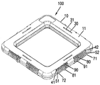
- FIG. 1 is a perspective view of a magnetic block formed with a surface structure of the present invention
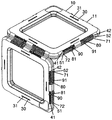
- Figure 2 is a perspective view of the vertical joint of the magnetic block of the present invention
- Figure 3 is a perspective view of the vertical junction of the magnetic block of the present invention.
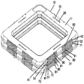
- Figure 4 is a perspective view of a horizontal junction of the magnetic block of the present invention.
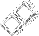
- Figure 5a is a view showing that after the horizontal bonding of the blocks formed with the surface structure according to the prior art push in the opposite side direction
- Figure 5b is a view showing that after the horizontal bonding of the blocks formed with the surface structure according to the present invention push in the opposite direction to each other.
- FIG. 1 is a perspective view of a magnetic block formed with a surface structure of the present invention
- Figure 2 is a perspective view of a vertical joint of the magnetic block of the present invention.
- Block 100 of the block toy in which the magnet of the present invention is built is made of a block by combining the upper frame 10 and the lower frame 20 has a square panel shape with a hollow in the center, the upper frame ( 10) and the inner center of the four sides of the lower frame 20 is formed with a magnet mounting groove (not shown) to secure the internal space for the rotational drive of the magnet to form one or two cylindrical magnets (not shown) ) Is built side by side with the longitudinal direction of the edge.
- the number of poles is increased as compared with the case where one magnet is embedded, and the two magnets are more strongly attracted to each other when the two frames are joined.
- the block 100 to which the upper frame 10 and the lower frame 20 are coupled is preferably formed in the form of a panel having a hollow in the center with a width of 60 to 70 mm and a thickness of 6 to 9 mm, respectively. This is because, when the length is less than 60 mm and the thickness of 6 mm, respectively, the block becomes too small as a block toy, and when the width exceeds 70 mm and the thickness is 9 mm, the block becomes too large as a block toy.
- the block 100 in which the upper frame 10 and the lower frame 20 are combined is a panel having a hollow portion in the middle of 65 mm in width and 7 mm in thickness, respectively, and the width of each of the four sides is 11 mm. Is formed.
- the horizontal protrusions 30 and the insertion grooves 31 are alternately arranged in parallel with the edges at regular intervals.
- the horizontal protrusion 30 of the upper surface 11 of the upper frame 10 of the block located below is placed thereon.
- the lower frame of the other block mounted on the insertion groove 31 of the upper frame 10 of the block located below It is formed so that the horizontal projection 30 of the lower surface 21 of the (20).
- the depth of the horizontal protrusion 30 and the insertion groove 31 is preferably formed equal to 0.8 ⁇ 1.0mm, which is horizontal if the depth of the horizontal protrusion 30 and the insertion groove 31 is less than 0.8mm
- the engagement force between the protrusion 30 and the insertion groove 31 is weakened, and when the depth of the horizontal protrusion 30 and the insertion groove 31 exceeds 1.0 mm, the horizontal protrusion 30 protrudes too high to block the This is because it causes inconvenience to use.
- the height of the horizontal protrusion 30 and the depth of the insertion groove 31 is formed to 0.9mm.
- the surface structure of the block as described above is used for vertical joining between the blocks of the present invention, even if the external force is applied in the lateral direction instead of the direction in which the joint is firmly joined without any sideways.
- FIG 3 is a perspective view of a vertical junction of the magnetic block of the present invention
- Figure 4 is a perspective view of a horizontal junction of the magnetic block of the present invention.
- An upper inclined surface 40 extends from an edge of the upper frame 10 to be 45 degrees downward, and extends downward from the upper inclined surface 40 to form an upper vertical surface 50.
- the lower frame 20 The lower inclined surface 60 is formed to extend from the edge of the 45 ° angle upward, and the lower vertical surface 70 is extended upward from the lower inclined surface 60.
- the upper inclined surface (40) has a predetermined gap based on a position slightly biased from the center to the left side, and the left and right engaging jaws (41) are formed in three stages of upper, middle, and lower, and the upper, middle, and lower three stages are caught on the right side.
- the groove 42 is formed to be slightly lower and longer than the locking jaw 41, and the lower inclined surface 60 has a predetermined gap on the left side with a predetermined interval based on a position slightly biased from the center to the upper, middle, and lower three stages.
- 62 is formed and the upper and lower engaging jaw 61 is formed slightly higher and shorter than the engaging groove 62 in three stages.
- the locking jaw 51 is formed on the left side at a predetermined interval based on the position slightly biased from the center to the left side, and the locking groove 52 is formed on the right side slightly lower and longer than the locking jaw 51.
- the locking groove 72 is formed on the left side at a predetermined interval based on the position slightly biased from the center to the right side, and the locking jaw 71 is formed on the right side slightly shorter than the locking groove 72. do.
- the locking jaws 41, 51, 61, and 71 perpendicular to the locking grooves 42 and 52.
- the upper protruding jaw 80 is formed higher than the height of the upper surface, and the locking jaws 41 and 51 at the middle of the locking jaw 41 on the left side of the upper inclined surface 40 and the upper left of the upper vertical surface 50.
- the upper insertion groove 90 is formed in the vertical direction, and the locking groove 62 on the left side of the lower inclined surface 60 and the locking groove 72 on the left side of the lower vertical surface 70 on the locking grooves 62 and 72.
- the lower protrusion jaw 81 is formed higher than the height of the locking jaws 41, 51, 61, and 71 in the vertical direction, and the locking jaw 61 on the right side of the lower inclined surface 60 and the locking jaw on the right side of the lower vertical surface 70 are formed. (71) In the middle portion, the lower insertion groove 91 is formed in the direction perpendicular to the locking jaw (61, 71).
- the locking grooves 42 and 62 are formed slightly lower and longer than the locking projections 41 and 61, and the locking projections 41 and 61 are locking grooves 42.
- the reason why it is formed slightly higher and shorter than that of 62 is to allow the locking projections 41 and 61 to be easily fitted into the locking grooves 42 and 62.
- the depth of each groove of the locking grooves 42 and 62 and the height of each jaw of the locking jaws 41 and 61 are It is preferable to be formed in each of 0.25 ⁇ 0.35mm, which is, for example, if the depth of each groove of the locking grooves (42, 62) and the height of each jaw of the locking projections (41, 61) is less than 0.25mm, for example
- the engaging force between the engaging jaw 41 of the upper inclined surface 40 and the engaging groove 62 of the lower inclined surface 60 becomes too weak, and the protruding jaws 80 and 81 and the insertion grooves 90 and 91 are also formed.
- the height of the locking jaws 41 and 61 is 0.35 mm
- the depth of the locking grooves 42 and 62 is 0.3 mm.
- the locking grooves 52, 72 are formed slightly lower and longer than the locking projections 51, 71, and the locking projections 51, 71 are locking grooves 52.
- the reason why it is formed slightly higher and shorter than that of 72 is to allow the locking projections 51 and 71 to be easily fitted into the locking grooves 52 and 72.
- the depths of the locking grooves 52 and 72 and the heights of the locking jaws 51 and 71 are 0.4 to 0.6 mm, respectively. It is preferable to be formed, which is, when the depth of the locking grooves 52 and 72 and the height of the locking jaws 51 and 71 are less than 0.4 mm, between the locking grooves 52 and 72 and the locking jaws 51 and 71.
- the engagement force is too weak, and the projection jaw (80, 81) and the insertion groove (90, 91) is also formed, so the depth of each groove of the engaging groove (52, 72) and the locking jaw (51, 71) This is because the engaging force between the locking jaws 51 and 71 and the locking grooves 52 and 72 does not need to be strong until the height of each jaw exceeds 0.6 mm, respectively.
- the height of the locking projections 51 and 71 is 0.55 mm
- the depth of the locking grooves 52 and 72 is 0.5 mm.
- the protrusion jaw (80, 81) is formed in the middle of the locking grooves (42, 52, 62, 72) and the insertion groove (90, 91) is formed in the middle of the locking jaw (41, 51, 61, 71)
- the reason why the insertion hole (90, 91) is not protruding to the surface even if it is formed so that the insertion groove (90, 91) is inserted into the projection jaw (80, 81) is the engaging groove (42, 52, 62, 72) It is formed on the higher engaging jaw (41, 51, 61, 71), protruding jaw (80, 81) is protruding to the surface when it is formed, if the protruding jaw (80, 81) is formed to protrude a lot of block toys Since the use of the protruding jaw (80, 81) is formed in the engaging groove (42, 52, 62, 72) is lower than the locking jaw (41, 51. 61, 71) the locking jaw (41
- the height of the protruding jaw (80, 81) and the depth of the insertion groove (90, 91) is preferably formed to be 0.8 ⁇ 1.0mm, which is the case when the height of the protruding jaw (80, 81) is less than 0.8mm
- the engagement force between the upper projection jaw 80 and the lower insertion groove 91 is too weak, and if the height of the projection jaw (80, 81) exceeds 1.0mm, the projection jaw (80, 81) is too This is because it protrudes a lot and causes inconvenience in using the block toy.
- the depths of the protrusions 80 and 81 and the insertion grooves 90 and 91 are 0.9 mm.
- the surface structure of the block as described above is used for vertical joining, horizontal joining between the blocks, in the vertical joining of the two blocks of the present invention, for example, the locking step 41 of the upper inclined surface 40 of the block located vertically In the locking groove 42, the locking groove 62 and the locking jaw 61 of the lower inclined surface 60 of the block horizontally engaged with each other are engaged with each other, and the upper protrusion jaw 80 of the vertically positioned block is horizontal.
- the lower protruding jaw 81 of the block positioned horizontally is inserted into the lower inserting groove 91 of the block positioned in the vertical direction, and the joint is formed when the vertical joining is performed. Even if the external force acts in the lateral direction, it is firmly joined without being pushed to the side at all.
- the locking jaw 71 of the lower vertical surface 70 of one block and the locking groove 72 are the locking grooves 52 of the upper upper surface 50 of the other block.
- the engaging jaw 51 is engaged with each other, and the upper protruding jaw 80 on the right side of the upper vertical plane 50 of one block is inserted into the upper insertion groove 90 on the left side of the upper vertical plane 50 of the other block,
- the lower protruding jaw 81 on the left side of the lower vertical surface 70 of one block is inserted into the lower insertion hole 91 on the right side of the lower vertical surface 70 of the other block, so that the external force is applied in the lateral direction rather than in the direction in which the bonding is performed in the horizontal bonding. Even if this action is carried out, it is firmly bonded without being pushed to the side at all.
- Such a configuration is the same on each of the four sides and the edge of the block 100 of the present invention having a square panel form.
- the block according to the present invention is protruding jaw (80, 81) is slightly protruding but the height is less than 1.0mm, and the top and bottom joints, vertical joints, horizontal joints between the blocks are made firmly without causing inconvenience to the use of block toys In particular, even if the external force acts in the lateral direction other than the direction in which the bonding is made, it does not push at all.
- Figure 5a is a diagram showing the pushed in the opposite side direction after the horizontal bonding of the blocks formed with the surface structure according to the prior art
- Figure 5b is a side opposite to each other after the horizontal bonding of the blocks formed with the surface structure according to the present invention It is a figure which shows pushing.
- the shape of the block is square, but the shape of the block is not limited thereto, and blocks of various shapes such as rectangular, triangular, hexagonal, and octagonal shapes can be used.
Abstract
La présente invention concerne une structure de surface pour assembler des blocs d'éléments à aimant intégré destinés à être couplés à un jouet en blocs, la structure de surface permettant un assemblage stable entre chaque bloc tout en permettant à des structures en forme de partie saillante et de rainure, qui sont formées sur les surfaces de chacun des éléments à aimant intégré assemblés de haut en bas, assemblés verticalement et assemblés horizontalement, de s'emboîter naturellement les uns avec les autres, en formant une structure en forme de partie saillante et de rainure sur la surface des éléments à aimant intégré à coupler avec un jouet en blocs.
Applications Claiming Priority (2)
| Application Number | Priority Date | Filing Date | Title |
|---|---|---|---|
| KR2020150008560U KR200482829Y1 (ko) | 2015-12-28 | 2015-12-28 | 자석이 내장되는 블록완구의 블록 간 접합을 위한 표면구조 |
| KR20-2015-0008560 | 2015-12-28 |
Publications (1)
| Publication Number | Publication Date |
|---|---|
| WO2017115900A1 true WO2017115900A1 (fr) | 2017-07-06 |
Family
ID=58025861
Family Applications (1)
| Application Number | Title | Priority Date | Filing Date |
|---|---|---|---|
| PCT/KR2016/000024 WO2017115900A1 (fr) | 2015-12-28 | 2016-01-05 | Structure de surface pour assembler des blocs d'un jouet en blocs comprenant un aimant |
Country Status (6)
| Country | Link |
|---|---|
| US (1) | US20170182429A1 (fr) |
| JP (1) | JP2017119088A (fr) |
| KR (1) | KR200482829Y1 (fr) |
| CN (1) | CN205965029U (fr) |
| DE (1) | DE202016107352U1 (fr) |
| WO (1) | WO2017115900A1 (fr) |
Families Citing this family (9)
| Publication number | Priority date | Publication date | Assignee | Title |
|---|---|---|---|---|
| CN206700770U (zh) * | 2017-05-17 | 2017-12-05 | 汕头市信必达早教科技有限公司 | 一种磁力积木 |
| CN108064318B (zh) * | 2017-11-15 | 2020-09-04 | 佛山市爱迪尔卫浴有限公司 | 一种拉手组件及淋浴门 |
| CN109078341A (zh) * | 2018-09-25 | 2018-12-25 | 塞伦斯玩具(上海)有限公司 | 一种磁力片 |
| IT201900001229A1 (it) * | 2019-01-28 | 2020-07-28 | Plastwood Italia S R L | Assieme magnetico |
| USD973788S1 (en) * | 2020-07-16 | 2022-12-27 | Gymworld Inc. | Toy block |
| US20220233969A1 (en) * | 2021-01-22 | 2022-07-28 | Retrospective Goods, LLC | Magnetic construction tile set |
| US20220297021A1 (en) * | 2021-03-18 | 2022-09-22 | Dreambuilder Toy LLC | Magnetic Toy Device |
| USD1016929S1 (en) * | 2021-10-20 | 2024-03-05 | Lone Star Merchandising Group Inc. | Magnetic building tile having a gear shape design |
| USD981496S1 (en) * | 2022-07-19 | 2023-03-21 | Wuyi Lizewei Industry And Trade Co., Ltd. | Magnetic tiles set |
Citations (5)
| Publication number | Priority date | Publication date | Assignee | Title |
|---|---|---|---|---|
| KR100546070B1 (ko) * | 2005-05-31 | 2006-01-26 | (주)마그넷포유 | 패널형 자석놀이완구 |
| JP2006304950A (ja) * | 2005-04-27 | 2006-11-09 | Magnet 4U Co Ltd | パネル型磁石おもちゃ |
| KR100856094B1 (ko) * | 2007-03-30 | 2008-09-03 | 주식회사 오르다코리아 | 자석 블록 |
| KR20120097088A (ko) * | 2011-02-24 | 2012-09-03 | 김미애 | 자석 블록 완구의 블록 구성물 및 동 구성물을 포함한 자석 블록 완구 |
| KR200475198Y1 (ko) * | 2014-03-21 | 2014-11-12 | 최소영 | 자석이 내장된 블록완구의 블록 간 접합을 위한 표면구조 |
Family Cites Families (18)
| Publication number | Priority date | Publication date | Assignee | Title |
|---|---|---|---|---|
| DE1158426B (de) * | 1962-01-18 | 1963-11-28 | W Lepper Dr Ing | Magnetische Bauspielelemente |
| US6142848A (en) * | 1992-08-28 | 2000-11-07 | Geo Australia Pty. Limited | Educational toy components |
| GB2303267B (en) | 1995-06-06 | 2000-03-22 | Sony Uk Ltd | Video compression |
| JP3048280U (ja) * | 1997-10-22 | 1998-05-06 | ピープル株式会社 | 組立式軌道玩具 |
| US6431936B1 (en) * | 2000-04-28 | 2002-08-13 | People Co., Ltd. | Building toy |
| US6557955B2 (en) * | 2001-01-13 | 2003-05-06 | Darren Saravis | Snap together modular storage |
| KR100430854B1 (ko) * | 2002-01-29 | 2004-05-10 | 주식회사 토야 | 조립식 블록완구 세트 |
| US7160170B2 (en) * | 2005-04-20 | 2007-01-09 | Magnet 4 U Co., Ltd. | Panel-type magnetic toys |
| US7438623B2 (en) * | 2005-09-06 | 2008-10-21 | Wen-Pin Lin | Geometric construction system |
| CN104115335A (zh) * | 2009-02-02 | 2014-10-22 | 艾派克斯技术股份有限公司 | 挠性磁性互连 |
| US8366507B2 (en) * | 2010-07-19 | 2013-02-05 | Ying-Jen Chen | Building toy block set |
| US8458863B2 (en) * | 2011-11-03 | 2013-06-11 | Sparkling Sky International Limited | Magnetic connector apparatus and related systems and methods |
| US9022829B2 (en) * | 2012-01-13 | 2015-05-05 | LaRose Industries, LLC | Magnetic module and construction kit |
| KR101349152B1 (ko) * | 2013-02-12 | 2014-01-16 | 윤정석 | 자석 블록 완구 |
| KR101491599B1 (ko) * | 2013-06-21 | 2015-02-06 | (주)짐월드 | 블록완구 |
| JP5485456B1 (ja) * | 2013-08-13 | 2014-05-07 | 光昭 塩路 | 組立玩具 |
| US20160074766A1 (en) * | 2014-09-11 | 2016-03-17 | Click-Block Corporation | Surface structure for combining block of block toy having magnet inside |
| JP2016131874A (ja) * | 2015-01-20 | 2016-07-25 | 株式会社インザブロックIn the block Co.,Ltd. | 組立式ブロック玩具 |
-
2015
- 2015-12-28 KR KR2020150008560U patent/KR200482829Y1/ko active IP Right Grant
-
2016
- 2016-01-05 WO PCT/KR2016/000024 patent/WO2017115900A1/fr active Application Filing
- 2016-07-14 CN CN201620744758.0U patent/CN205965029U/zh not_active Expired - Fee Related
- 2016-12-06 US US15/371,007 patent/US20170182429A1/en not_active Abandoned
- 2016-12-07 JP JP2016238021A patent/JP2017119088A/ja active Pending
- 2016-12-23 DE DE202016107352.9U patent/DE202016107352U1/de active Active
Patent Citations (5)
| Publication number | Priority date | Publication date | Assignee | Title |
|---|---|---|---|---|
| JP2006304950A (ja) * | 2005-04-27 | 2006-11-09 | Magnet 4U Co Ltd | パネル型磁石おもちゃ |
| KR100546070B1 (ko) * | 2005-05-31 | 2006-01-26 | (주)마그넷포유 | 패널형 자석놀이완구 |
| KR100856094B1 (ko) * | 2007-03-30 | 2008-09-03 | 주식회사 오르다코리아 | 자석 블록 |
| KR20120097088A (ko) * | 2011-02-24 | 2012-09-03 | 김미애 | 자석 블록 완구의 블록 구성물 및 동 구성물을 포함한 자석 블록 완구 |
| KR200475198Y1 (ko) * | 2014-03-21 | 2014-11-12 | 최소영 | 자석이 내장된 블록완구의 블록 간 접합을 위한 표면구조 |
Also Published As
| Publication number | Publication date |
|---|---|
| JP2017119088A (ja) | 2017-07-06 |
| CN205965029U (zh) | 2017-02-22 |
| US20170182429A1 (en) | 2017-06-29 |
| DE202016107352U1 (de) | 2017-04-19 |
| KR200482829Y1 (ko) | 2017-03-22 |
Similar Documents
| Publication | Publication Date | Title |
|---|---|---|
| WO2017115900A1 (fr) | Structure de surface pour assembler des blocs d'un jouet en blocs comprenant un aimant | |
| WO2015141927A1 (fr) | Structure de surface permettant d'assembler des blocs d'un jouet en blocs où un aimant est incorporé | |
| US9895623B2 (en) | Toy couplers including a plurality of block retaining channels | |
| US8968046B2 (en) | Toy couplers including a plurality of block retaining channels | |
| WO2014126271A1 (fr) | Jouet en bloc aimanté | |
| WO2017209344A1 (fr) | Ensemble de jeu de blocs de construction | |
| US9863145B2 (en) | Masonry block system | |
| US20170120158A1 (en) | Toy couplers including a plurality of block retaining channels | |
| NO20013364L (no) | Lekebyggesett med sammenkopling ved hjelp av snepptapper | |
| WO2016015487A1 (fr) | Bloc de construction jouet facilement façonnable | |
| RU2017101860A (ru) | Строительный блок и фасадная стена, выполненная с использованием таких блоков | |
| CN207286689U (zh) | 一种拼插式积木底板 | |
| KR20150002928U (ko) | 조립식 매트 | |
| RU2613514C2 (ru) | Модульная конструкционная система | |
| WO2017131278A1 (fr) | Blocs solides de jeu à blocs, comportant des éléments d'accouplement | |
| WO2017126912A1 (fr) | Bloc de jeu et procédé de fabrication associé | |
| KR200483151Y1 (ko) | 하나의 프레임으로 만들어져 자석내장부재가 결합되는 블록완구의 블록 간 접합을 위한 표면구조 | |
| KR200466927Y1 (ko) | 자석완구 | |
| KR200482828Y1 (ko) | 블록완구에 결합되는 자석내장부재의 블록 간 접합을 위한 표면구조 | |
| CN202920995U (zh) | 一种拼装玩具 | |
| KR200479878Y1 (ko) | 블록 지지대를 갖는 블록완구 | |
| CN102949854A (zh) | 磁性积木 | |
| KR20190002922U (ko) | 산업용 랙 시스템용 사각 알루미늄 프로파일, 랙 조인트 및 수직 연결 부재 | |
| CN217163204U (zh) | 积木玩具 | |
| CN215310223U (zh) | 一种机器人赛场 |
Legal Events
| Date | Code | Title | Description |
|---|---|---|---|
| 121 | Ep: the epo has been informed by wipo that ep was designated in this application |
Ref document number: 16881853 Country of ref document: EP Kind code of ref document: A1 |
|
| NENP | Non-entry into the national phase |
Ref country code: DE |
|
| 122 | Ep: pct application non-entry in european phase |
Ref document number: 16881853 Country of ref document: EP Kind code of ref document: A1 |