WO2017113511A1 - 一种多电机驱动的送风设备恒风量控制方法 - Google Patents
一种多电机驱动的送风设备恒风量控制方法 Download PDFInfo
- Publication number
- WO2017113511A1 WO2017113511A1 PCT/CN2016/075898 CN2016075898W WO2017113511A1 WO 2017113511 A1 WO2017113511 A1 WO 2017113511A1 CN 2016075898 W CN2016075898 W CN 2016075898W WO 2017113511 A1 WO2017113511 A1 WO 2017113511A1
- Authority
- WO
- WIPO (PCT)
- Prior art keywords
- air volume
- motor
- constant air
- bldc
- data processor
- Prior art date
- Legal status (The legal status is an assumption and is not a legal conclusion. Google has not performed a legal analysis and makes no representation as to the accuracy of the status listed.)
- Ceased
Links
Images




Classifications
-
- H—ELECTRICITY
- H02—GENERATION; CONVERSION OR DISTRIBUTION OF ELECTRIC POWER
- H02P—CONTROL OR REGULATION OF ELECTRIC MOTORS, ELECTRIC GENERATORS OR DYNAMO-ELECTRIC CONVERTERS; CONTROLLING TRANSFORMERS, REACTORS OR CHOKE COILS
- H02P6/00—Arrangements for controlling synchronous motors or other dynamo-electric motors using electronic commutation dependent on the rotor position; Electronic commutators therefor
- H02P6/04—Arrangements for controlling or regulating the speed or torque of more than one motor
-
- F—MECHANICAL ENGINEERING; LIGHTING; HEATING; WEAPONS; BLASTING
- F24—HEATING; RANGES; VENTILATING
- F24F—AIR-CONDITIONING; AIR-HUMIDIFICATION; VENTILATION; USE OF AIR CURRENTS FOR SCREENING
- F24F11/00—Control or safety arrangements
- F24F11/70—Control systems characterised by their outputs; Constructional details thereof
- F24F11/72—Control systems characterised by their outputs; Constructional details thereof for controlling the supply of treated air, e.g. its pressure
- F24F11/74—Control systems characterised by their outputs; Constructional details thereof for controlling the supply of treated air, e.g. its pressure for controlling air flow rate or air velocity
- F24F11/75—Control systems characterised by their outputs; Constructional details thereof for controlling the supply of treated air, e.g. its pressure for controlling air flow rate or air velocity for maintaining constant air flow rate or air velocity
-
- H—ELECTRICITY
- H02—GENERATION; CONVERSION OR DISTRIBUTION OF ELECTRIC POWER
- H02P—CONTROL OR REGULATION OF ELECTRIC MOTORS, ELECTRIC GENERATORS OR DYNAMO-ELECTRIC CONVERTERS; CONTROLLING TRANSFORMERS, REACTORS OR CHOKE COILS
- H02P5/00—Arrangements specially adapted for regulating or controlling the speed or torque of two or more electric motors
- H02P5/46—Arrangements specially adapted for regulating or controlling the speed or torque of two or more electric motors for speed regulation of two or more dynamo-electric motors in relation to one another
- H02P5/50—Arrangements specially adapted for regulating or controlling the speed or torque of two or more electric motors for speed regulation of two or more dynamo-electric motors in relation to one another by comparing electrical values representing the speeds
-
- H—ELECTRICITY
- H02—GENERATION; CONVERSION OR DISTRIBUTION OF ELECTRIC POWER
- H02P—CONTROL OR REGULATION OF ELECTRIC MOTORS, ELECTRIC GENERATORS OR DYNAMO-ELECTRIC CONVERTERS; CONTROLLING TRANSFORMERS, REACTORS OR CHOKE COILS
- H02P5/00—Arrangements specially adapted for regulating or controlling the speed or torque of two or more electric motors
- H02P5/74—Arrangements specially adapted for regulating or controlling the speed or torque of two or more electric motors controlling two or more AC dynamo-electric motors
-
- H—ELECTRICITY
- H02—GENERATION; CONVERSION OR DISTRIBUTION OF ELECTRIC POWER
- H02M—APPARATUS FOR CONVERSION BETWEEN AC AND AC, BETWEEN AC AND DC, OR BETWEEN DC AND DC, AND FOR USE WITH MAINS OR SIMILAR POWER SUPPLY SYSTEMS; CONVERSION OF DC OR AC INPUT POWER INTO SURGE OUTPUT POWER; CONTROL OR REGULATION THEREOF
- H02M7/00—Conversion of AC power input into DC power output; Conversion of DC power input into AC power output
- H02M7/42—Conversion of DC power input into AC power output without possibility of reversal
- H02M7/44—Conversion of DC power input into AC power output without possibility of reversal by static converters
- H02M7/48—Conversion of DC power input into AC power output without possibility of reversal by static converters using discharge tubes with control electrode or semiconductor devices with control electrode
- H02M7/53—Conversion of DC power input into AC power output without possibility of reversal by static converters using discharge tubes with control electrode or semiconductor devices with control electrode using devices of a triode or transistor type requiring continuous application of a control signal
- H02M7/537—Conversion of DC power input into AC power output without possibility of reversal by static converters using discharge tubes with control electrode or semiconductor devices with control electrode using devices of a triode or transistor type requiring continuous application of a control signal using semiconductor devices only, e.g. single switched pulse inverters
- H02M7/5387—Conversion of DC power input into AC power output without possibility of reversal by static converters using discharge tubes with control electrode or semiconductor devices with control electrode using devices of a triode or transistor type requiring continuous application of a control signal using semiconductor devices only, e.g. single switched pulse inverters in a bridge configuration
- H02M7/53871—Conversion of DC power input into AC power output without possibility of reversal by static converters using discharge tubes with control electrode or semiconductor devices with control electrode using devices of a triode or transistor type requiring continuous application of a control signal using semiconductor devices only, e.g. single switched pulse inverters in a bridge configuration with automatic control of output voltage or current
-
- H—ELECTRICITY
- H02—GENERATION; CONVERSION OR DISTRIBUTION OF ELECTRIC POWER
- H02P—CONTROL OR REGULATION OF ELECTRIC MOTORS, ELECTRIC GENERATORS OR DYNAMO-ELECTRIC CONVERTERS; CONTROLLING TRANSFORMERS, REACTORS OR CHOKE COILS
- H02P6/00—Arrangements for controlling synchronous motors or other dynamo-electric motors using electronic commutation dependent on the rotor position; Electronic commutators therefor
- H02P6/04—Arrangements for controlling or regulating the speed or torque of more than one motor
- H02P2006/045—Control of current
-
- Y—GENERAL TAGGING OF NEW TECHNOLOGICAL DEVELOPMENTS; GENERAL TAGGING OF CROSS-SECTIONAL TECHNOLOGIES SPANNING OVER SEVERAL SECTIONS OF THE IPC; TECHNICAL SUBJECTS COVERED BY FORMER USPC CROSS-REFERENCE ART COLLECTIONS [XRACs] AND DIGESTS
- Y02—TECHNOLOGIES OR APPLICATIONS FOR MITIGATION OR ADAPTATION AGAINST CLIMATE CHANGE
- Y02B—CLIMATE CHANGE MITIGATION TECHNOLOGIES RELATED TO BUILDINGS, e.g. HOUSING, HOUSE APPLIANCES OR RELATED END-USER APPLICATIONS
- Y02B30/00—Energy efficient heating, ventilation or air conditioning [HVAC]
- Y02B30/70—Efficient control or regulation technologies, e.g. for control of refrigerant flow, motor or heating
Definitions
- the invention relates to a constant air volume control method for a multi-motor driven air supply device.
- the constant air volume control of the fan equipment on the market is a BLDC motor with only one constant air volume control in the load to drive the wind wheel or the fan.
- This constant air volume controlled BLDC motor is designed according to parameters such as load power and a constant air volume control strategy is established.
- the object of the present invention is to provide a constant air volume control method for a multi-motor driven air supply device, which is simple in design and convenient to implement, can effectively shorten development time and cost, and reliably realize constant air volume control.
- each BLDC motor includes a control driving circuit board and a motor entity
- the driving circuit board includes a power circuit, a microprocessor, a motor operating parameter detecting circuit, and an inverter circuit.
- the rotor position measuring circuit the power circuit supplies power to each part of the circuit
- the rotor position measuring circuit detects the rotor position signal and inputs it to the microprocessor
- the motor operating parameter detecting circuit inputs the detected electrical parameter to the microprocessor
- the microprocessor controls the inverse
- the variable circuit works, and the output end of the inverter circuit is connected to each phase coil winding of the stator assembly.
- the constant air volume data processor described above is a digital signal processor DSP or a single chip MCU.
- the constant air volume data processor described above is wired or wirelessly communicated with each BLDC motor.
- Each of the BLDC motors described above adopts a motor with high precision control, and the error between the speed commanded by the constant air volume data processor and the actual running speed of the motor is within a range of plus or minus three revolutions.
- Each BLDC motor described above feeds back the motor operating parameter C to the constant air volume data processor as a power parameter or a current parameter.
- the constant air volume Q value in the constant air volume data processor described above can be determined by an external input.
- control drive circuit board described above can be integrated with the motor body.
- control drive circuit board described above can be separated from the motor body.
- control drive circuit board and the constant air volume data processor of each BLDC motor described above can be integrated on the same circuit board.
- the constant air volume data processor described above directly replaces the microprocessor of the control drive circuit board of each BLDC motor.
- the constant air volume data processor When each BLDC motor feeds back the motor operating parameter C to the constant air volume data processor as the power parameter P, the constant air volume data processor accumulates the power parameters fed back by each BLDC motor to form a total power P, and substitutes the total power into the constant power.
- the air volume control function Q F(n, P) calculates the motor speed n when a constant air volume is maintained.
- each BLDC motor feeds back the motor operating parameter C to the constant air volume data processor is the bus bar
- the invention has the following effects:
- the constant air volume data processor By making each BLDC motor into a speed closed-loop control motor, the constant air volume data processor sends the same speed signal command to each BLDC motor, so that the running speed of each BLDC motor is the same or equivalent; each BLDC motor The motor operating parameters are fed back to the constant air volume data processor, and the constant air volume data processor calculates the motor speed n when the constant air volume is maintained according to the motor running parameters fed back by each BLDC motor, and then sends the same speed signal command to each BLDC motor.
- the design is simple, the implementation is convenient, the development time and cost can be effectively shortened, and the constant air volume control can be reliably realized.
- BLDC motors are of the same specification and can be more conveniently and reliably controlled
- control drive circuit board can be integrated with the motor body to make the structure more compact
- control drive circuit board of each BLDC motor and the constant air volume data processor can be integrated on the same circuit board, which can reduce the repeated setting of the circuit.
- power circuits can further reduce product costs.
- Embodiment 1 is a schematic structural view of Embodiment 1 of the present invention.
- Figure 2 is a perspective view of a DC brushless motor in the first embodiment of the present invention
- Embodiment 3 is an exploded view of a DC brushless motor in Embodiment 1 of the present invention.
- Figure 5 is a plan view of a DC brushless motor in Embodiment 1 of the present invention.
- Figure 6 is a cross-sectional view taken along line A-A of Figure 5 of the present invention.
- Figure 7 is a block diagram showing the circuit of the control driving circuit board in the first embodiment of the present invention.
- Figure 8 is a circuit diagram corresponding to Figure 7;
- Figure 9 is a graph showing a family of constant air volume fitting curves measured by an experiment of Example 1 of the present invention.
- Figure 10 is a graph showing the fitting of the five-group constant air volume measured by an experiment in Example 1 of the present invention.
- Figure 11 is a schematic view showing the structure of the second embodiment of the present invention.
- Figure 12 is a schematic structural view of Embodiment 4 of the present invention.
- Embodiment 1 is a diagrammatic representation of Embodiment 1:
- the BLDC motor includes a motor body and a control driving circuit board 6.
- the motor body includes a rotating shaft 1, a rotor assembly 2, a stator assembly 3, a casing 4 and an end.
- the cover 5 the rotor assembly 2 is mounted on the rotating shaft 1, the stator assembly 3 is mounted with the casing 4 and nested outside the rotor assembly 2, and the end cover 5 is mounted on the end of the casing 4, and the two ends of the rotating shaft 1 are respectively supported
- the control driving circuit board 6 is mounted in the cavity 10 surrounded by the end cover 5 and the casing 4, and the speed regulating potentiometer 7 is soldered and mounted on the control driving circuit board 6, this embodiment
- the cavity 50 is opened on the inner side surface of the front end cover or the rear end cover, and the control driving circuit board 6 is installed in the cavity. 50 inside.
- the constant air volume data processor is located outside each BLDC motor.
- Each BLDC motor includes a control drive circuit board and a motor entity.
- the drive circuit board includes a power supply circuit, a microprocessor, a motor operating parameter detection circuit, an inverter circuit, and a rotor position measurement.
- the circuit and the power supply circuit supply power to each part of the circuit.
- the rotor position measuring circuit detects the rotor position signal and inputs it to the microprocessor.
- the motor running parameter detecting circuit inputs the detected electrical parameters to the microprocessor, and the microprocessor controls the inverter circuit to work.
- the output of the inverter circuit is connected to the coil windings of the phases of the stator assembly. As shown in Fig. 7 and Fig.
- the BLDC motor is a 3-phase brushless DC permanent magnet synchronous motor
- the motor operating parameter detecting circuit includes a rotor position measuring circuit and a bus bar.
- the current detecting circuit and the bus voltage detecting circuit, the rotor position measuring circuit generally adopts three Hall sensors, and the three Hall sensors respectively detect the rotor position of a 360-degree electrical angular period, and the stator assembly 12 is changed once every 120 degrees of electrical angle.
- the energization of each phase coil winding forms a 3-phase 6-step control mode.
- the DC bus current Ibus can be changed.
- the inverter circuit is composed of electronic switch tubes Q1, Q2, Q3, Q4, Q5 and Q6.
- the control terminals of the electronic switch tubes Q1, Q2, Q3, Q4, Q5 and Q6 are respectively output by the microprocessor.
- the 6-channel PWM signal (P1, P2, P3, P4, P5, P6) is controlled.
- the inverter circuit is also connected to the resistor R1 for detecting the bus current Ibus.
- the bus current detecting circuit converts the detected bus current Ibus of the resistor R1 and transmits it to microprocessor.
- the motor input power control is controlled by the electronic switch tube Q7, and the PWM signal output by the microprocessor, P0, is used to control the on-time of the electronic switch tube Q7 to control the motor input power.
- the rotor position measuring circuit detects the rotor position signal and inputs it to the microprocessor.
- the microprocessor calculates the real-time rotational speed V of the motor based on the rotor position signal, the bus current detecting circuit inputs the bus current to the microprocessor, and the bus voltage detecting circuit connects the DC bus.
- each BLDC motor is made into a speed closed loop control motor; 2) in a constant air volume data processor
- the speed signal command (compared to mean that the speed difference between the motor commands sent to the two BLDCs is within 1%), so that the speeds of the BLDC motors run at the same or equivalent, which means the actual speed error of the two BLDC motors.
- each target air volume corresponds to a set of C 1 , C 2 ,..., C m coefficients and is stored
- the development and mathematical model establishment of the Direct P Control for Constant Airflow Control Apparatus Method of the present invention is such that, in general, in a ventilation system, the fan is driven by a BLDC motor in a stable state.
- the air produced by the air.
- the power when the static pressure changes, is controlled by power and speed to maintain the constant air volume. As the static pressure increases, the power and speed change.
- a control model is developed that, when product control determines the air volume requirement, provides a constant air volume CFM at a specific static pressure by controlling power and speed.
- the characteristic curve represents the constant wind volume physical characteristics that maintain control power and speed.
- the process of curve fitting is to select a polynomial to describe the curve, and the coefficients of the polynomial can be obtained by the least squares method.
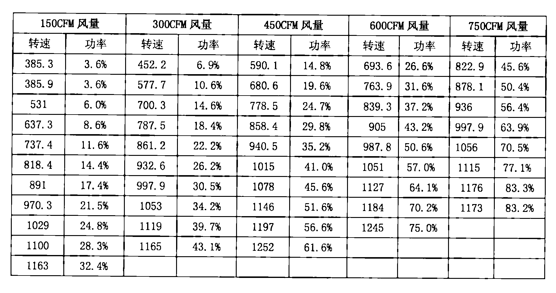
- Figure 10 is a plot of the experimental data of the direct power control constant air volume of a 1/3 HP PM motor in a small pipe HVAC system.
- the system selects some typical air volume CFM as a test point to build a test
- the database is used to build mathematical models. These typical points include the minimum and maximum air volume values, with some intermediate points added. According to the product specifications, the typical air volume CFM has five test points, 150/300/450/600 and 750 CFM.
- Table 2 shows an example of the test data results.
- the speed of the motor ranges from 200 to 1400 rpm; the static pressure of the system ranges from 0.1 to 1 H 2 O. Maintain the preset constant air volume CCFM output and obtain a value corresponding to the motor input power of Figure 11 to form a database.
- each predetermined CFM wind volume corresponds to a quadratic function of power and speed, obtained in a standard calculation method: these equations define the power and the speed of the operating point of any system at a particular static pressure.
- the motor system defines a function corresponding to it, and the trajectory of its working point follows the function definition. Equations (3) through (7) can be expressed as a standard equation, and C1, C2, and C3 are constants.
- the constant air volume Q value in the constant air volume data processor can be determined by external input, and the constant air volume is determined.
- the data processor stores a constant air volume control function for a plurality of test wind volume points, and if the input constant air volume IN-CFM request is not one of a modeling curve (a constant air volume control function of a plurality of test wind volume points), an interpolation is used. The method is to obtain a new characteristic equation to fit the requested constant air volume IN-CFM.
- the constant air volume data processor and each BLDC motor use wired or wireless communication.
- the constant air volume data processor can be a digital signal processor DSP or a single chip MCU.
- the constant air volume data processor communicates with the microprocessors in the control drive circuit boards 6 of the two BLDC motors, respectively.
- the two BLDC motors adopt high-precision controlled motors.
- the high-precision refers to the error between the speed of the constant air volume data processor command and the actual running speed of the motor in the range of plus or minus three revolutions.
- the two BLDC motors are of the same size, and the control drive circuit board can be integrated with the motor body.
- control drive circuit board can also be separated from the motor body, and the control drive of each BLDC motor
- the moving circuit board and the constant air volume data processor can be integrated on the same circuit board.
- Embodiment 2 is a diagrammatic representation of Embodiment 1:
- This embodiment is basically the same as the structural principle control method of the first embodiment.
- the present embodiment drives six wind wheels by three BLDC motors, including the first motor 100, the second motor 200, and the third motor 600 and 6.
- the wind turbine 400, the output shaft 1 of the first motor 100, the second motor 200 and the third motor 600 are respectively driven 400, the first motor 100, the second motor 200, the third motor 600 and 6 winds
- the wheel 400 is in the same air duct 500, and the first motor 100, the second motor 200, and the third motor 600 are BLDC motors of the same specification.
- Q is the air volume
- n is the motor running speed
- P is the motor input power.
- the same speed signal command sent by the constant air volume data processor to the three BLDC motors makes the running speed of each BLDC motor the same or equivalent, which means that the actual speed error of the two BLDC motors is within 1%;
- the BLDC motor respectively feeds the motor input power P1, P2, P3 to the constant air volume data processor, that is, the first motor 100 feeds back the motor input power P1 to the constant air volume data processor, and the second motor 200 feeds back the motor input power to the constant air volume data processor.
- the corresponding constant air volume control function is called, and the motor speed n when the constant air volume is maintained is calculated according to the feedback motor input total power P, and then the same speed signal is sent to each BLDC motor. instruction.
- the BLDC motor and the wind wheel are added according to the width of the air duct of the air supply device.
- four BLDC motors and eight wind wheels can be used.
- Embodiment 3 is a diagrammatic representation of Embodiment 3
- the signal command (equivalently means that the speed difference between the motor commands sent to the two BLDCs is within 1%), so that the running speeds of the BLDC motors are the same or equivalent, which means that the actual speed error of the two BLDC motors is 4% or less; 4)
- the motor speed is n and then
- the constant air volume data processor stores a constant air volume function of a plurality of wind volume points. It can realize constant air volume control of air supply equipment driven by two BLDC motors. Each BLDC motor only needs to follow the speed signal command sent by the constant air volume data processor, and it can run at the specified speed.
- Embodiment 4 is a diagrammatic representation of Embodiment 4:
- This embodiment is an improvement on the basis of the first embodiment: the control driving circuit board 6 of the two BLDC motors in the first embodiment is moved to the outside of the motor housing 4, because the control driving circuit boards 6 of the two BLDC motors 6 Both the constant air volume data processor and the constant air volume data processor need to be independently powered, the circuit structure is repeated, and the cost is increased. Now, the control drive circuit board 6 and the constant air volume data processor of the two BLDC motors are integrated on one circuit board, and the power supply circuit is supplied with power, and the repetition is repeated.
- the original control drive circuit board 6 of the two BLDC motors in the figure becomes the first control drive unit and the second control drive unit respectively, and the power supply circuit is simultaneously
- a control drive unit, a second control drive unit, and a constant air volume data processor provide power to save costs.
- the constant air volume data processor uses a high performance chip (has a higher computing speed and more I/O ports, then the microprocessor in the first control driving unit and the second control driving unit can be deleted directly from the constant
- the air volume data processor replaces its work, which further simplifies the structure and saves costs.
Landscapes
- Engineering & Computer Science (AREA)
- Power Engineering (AREA)
- Physics & Mathematics (AREA)
- Fluid Mechanics (AREA)
- Chemical & Material Sciences (AREA)
- Combustion & Propulsion (AREA)
- Mechanical Engineering (AREA)
- General Engineering & Computer Science (AREA)
- Control Of Multiple Motors (AREA)
- Control Of Positive-Displacement Air Blowers (AREA)
- Air Conditioning Control Device (AREA)
Abstract
Description


| CFM | C1 | C2 | C3 |
| 150 | 0.338 | -0.151 | 0.0458 |
| 300 | 0.4423 | -0.2113 | 0.0765 |
| 450 | 。。。 | 。。。 | 。。。 |
| 600 | 。。。 | 。。。 | 。。。 |
| 750 | 。。。 | 。。。 | 。。。 |
| 900 | 。。。 | 。。。 | 。。。 |


| 风量点(CFM) | |||
| 150 | 0.58 | -0.23 | 0.0224 |
| 300 | 0.66 | -0.33 | 0.0985 |
| 450 | 。。。 | 。。。 | 。。。 |
| 600 | 。。。 | 。。。 | 。。。 |
| 750 | 。。。 | 。。。 | 。。。 |
| 900 | 。。。 | 。。。 | 。。。 |
Claims (15)
- 一种多电机驱动的送风设备恒风量控制方法,所述的送风设备包括至少2台BLDC电机,每台BLDC电机各自驱动不同的风轮并处于同一风道内,其特征在于:1)将每台BLDC电机做成具速度闭环控制电机;2)在一个恒风量数据处理器里面存储恒风量控制函数Q=F(n,C),其中Q是风量,n是电机运行转速,C是电机运行参数;3)恒风量数据处理器向各台BLDC电机发送的相同的速度信号指令,使各台BLDC电机运行的转速相同或者相当;4)每台BLDC电机向恒风量数据处理器反馈电机运行参数C,恒风量数据处理器根据各台BLDC电机反馈的电机运行参数C计算出保持恒定风量时的电机速度n,然后向各台BLDC电机发送的相同的速度信号指令。
- 根据权利要求1所述的一种多电机驱动的送风设备恒风量控制方法,其特征在于:恒风量数据处理器位于各台BLDC电机外面,每台BLDC电机包括控制驱动线路板和电机实体,制驱动线路板包括电源电路、微处理器、电机运行参数检测电路、逆变电路和转子位置测量电路,电源电路为各部分电路供电,转子位置测量电路检测转子位置信号并输入到微处理器,电机运行参数检测电路将检测的电参数输入到微处理器,微处理器控制逆变电路工作,逆变电路的输出端连接定子组件的各相线圈绕组。
- 根据权利要求1所述的一种多电机驱动的送风设备恒风量控制方法,其特征在于:恒风量数据处理器是数字信号处理器DSP或者是单片机MCU。
- 根据权利要求1或2所述的一种多电机驱动的送风设备恒风量控制方法,其特征在于:恒风量数据处理器与各台BLDC电机采用有线或者无线通信。
- 根据权利要求4所述的一种多电机驱动的送风设备恒风量控制方法,其特征在于:所述的BLDC电机只有2台。
- 根据权利要求5所述的一种多电机驱动的送风设备恒风量控制方法,其特征在于:各台BLDC电机采用高精度控制的电机,恒风量数据处理器指令的转速与电机实际运行转速的误差在正负3转范围内。
- 根据权利要求1或2或3所述的一种多电机驱动的送风设备恒风量控制方法,其特征在于:每台BLDC电机向恒风量数据处理器反馈电机运行参数C是功率参数或者是电流参数。
- 根据权利要求7所述的一种多电机驱动的送风设备恒风量控制方法,其特征在于:恒风量数据处理器里面的恒定风量Q值可以由外部输入确定。
- 根据权利要求1或2所述的一种多电机驱动的送风设备恒风量控制方法,其特征在于:所有的BLDC电机是相同规格。
- 根据权利要求9所述的一种多电机驱动的送风设备恒风量控制方法,其特征在于:控制驱动线路板可以与电机实体造成一体。
- 根据权利要求1或2所述的一种多电机驱动的送风设备恒风量控制方法,其特征在于:控制驱动线路板可以与电机实体造成分体式。
- 根据权利要求11所述的一种多电机驱动的送风设备恒风量控制方法,其特征在于:各BLDC电机的控制驱动线路板与恒风量数据处理器可集成在同一块线路板上。
- 根据权利要求12所述的一种多电机驱动的送风设备恒风量控制方法,其特征在于:所述的恒风量数据处理器直接取代各BLDC电机的控制驱动线路板的微处理器。
- 根据权利要求7所述的一种多电机驱动的送风设备恒风量控制方法,其特征在于:当每台BLDC电机向恒风量数据处理器反馈电机运行参数C是功率参数P时,恒风量数据处理器将各台BLDC电机反馈的功率参数累加形成总功率P,将总功率代入恒风量控制函数Q=F(n,P)计算出保持恒定风量时的电机速度n。
- 根据权利要求7所述的一种多电机驱动的送风设备恒风量控制方法,其特征在于:当每台BLDC电机向恒风量数据处理器反馈电机运行参数C是母线电流参数时,恒风量数据处理器将各台BLDC电机反馈的母线电流参数累加形成总母线电流I,将总母线电流I代入恒风量控制函数Q=F(n,I)计算出保持恒 定风量时的电机速度n。
Priority Applications (3)
| Application Number | Priority Date | Filing Date | Title |
|---|---|---|---|
| MX2018008172A MX387033B (es) | 2015-12-31 | 2016-03-08 | Metodo de control de volumen de aire constante para un dispositivo de suministro de aire impulsado por motores multiples |
| CA3009707A CA3009707C (en) | 2015-12-31 | 2016-03-08 | Constant air volume control method for an air supply device driven by multiple motors |
| US16/012,739 US10690371B2 (en) | 2015-12-31 | 2018-06-19 | Method for outputting constant air volume by multi-motor driving system |
Applications Claiming Priority (2)
| Application Number | Priority Date | Filing Date | Title |
|---|---|---|---|
| CN201511034726.8 | 2015-12-31 | ||
| CN201511034726.8A CN106936342B (zh) | 2015-12-31 | 2015-12-31 | 一种多电机驱动的送风设备恒风量控制方法 |
Related Child Applications (1)
| Application Number | Title | Priority Date | Filing Date |
|---|---|---|---|
| US16/012,739 Continuation-In-Part US10690371B2 (en) | 2015-12-31 | 2018-06-19 | Method for outputting constant air volume by multi-motor driving system |
Publications (1)
| Publication Number | Publication Date |
|---|---|
| WO2017113511A1 true WO2017113511A1 (zh) | 2017-07-06 |
Family
ID=59224289
Family Applications (1)
| Application Number | Title | Priority Date | Filing Date |
|---|---|---|---|
| PCT/CN2016/075898 Ceased WO2017113511A1 (zh) | 2015-12-31 | 2016-03-08 | 一种多电机驱动的送风设备恒风量控制方法 |
Country Status (5)
| Country | Link |
|---|---|
| US (1) | US10690371B2 (zh) |
| CN (1) | CN106936342B (zh) |
| CA (1) | CA3009707C (zh) |
| MX (1) | MX387033B (zh) |
| WO (1) | WO2017113511A1 (zh) |
Cited By (4)
| Publication number | Priority date | Publication date | Assignee | Title |
|---|---|---|---|---|
| CN109357382A (zh) * | 2018-09-27 | 2019-02-19 | 四川长虹空调有限公司 | 空调恒风量控制方法 |
| CN109357360A (zh) * | 2018-09-27 | 2019-02-19 | 四川长虹空调有限公司 | 空调滤网脏堵情况检测与风量控制方法 |
| US10333436B2 (en) | 2017-11-29 | 2019-06-25 | Regal Beloit America, Inc. | Drive circuit for electric motors |
| US10554157B2 (en) | 2017-11-29 | 2020-02-04 | Regal Beloit America, Inc. | Drive circuit for electric motors |
Families Citing this family (9)
| Publication number | Priority date | Publication date | Assignee | Title |
|---|---|---|---|---|
| CN110239757A (zh) * | 2018-03-07 | 2019-09-17 | 上海艳灿电子科技有限公司 | 一种电动塑胶带打包机 |
| WO2019200813A1 (zh) | 2018-04-17 | 2019-10-24 | 中山大洋电机股份有限公司 | Bldc电机的转换电路板及应用其的旅馆用的空调控制系统 |
| CN109630447B (zh) * | 2018-11-01 | 2021-04-20 | 浙江铭振电子股份有限公司 | 一种风机墙的控制方法及风机墙 |
| CN112525306B (zh) * | 2019-09-18 | 2022-04-19 | 宁波方太厨具有限公司 | 楼宇集中式排烟系统中室内吸油烟机风量计算校正方法及系统 |
| CN111059736A (zh) * | 2019-12-04 | 2020-04-24 | 珠海格力电器股份有限公司 | 空调系统恒风量控制方法 |
| KR20230145793A (ko) * | 2022-04-11 | 2023-10-18 | 삼성전자주식회사 | 파라미터 차이가 있는 복수의 전동기를 구동하기 위한 방법 및 장치 |
| WO2024136094A1 (ko) * | 2022-12-22 | 2024-06-27 | 삼성전자 주식회사 | 가전 기기의 고장 진단 방법, 및 가전 기기 |
| CN221591293U (zh) * | 2023-11-09 | 2024-08-23 | 广东澳运科技有限公司 | 一种风扇的控制电路 |
| CN119687019B (zh) * | 2024-12-19 | 2025-10-14 | 电子科技大学中山学院 | 一种具有容错特性的多电机风机系统恒风量控制方法 |
Citations (6)
| Publication number | Priority date | Publication date | Assignee | Title |
|---|---|---|---|---|
| EP0821204A1 (fr) * | 1996-07-23 | 1998-01-28 | Gec Alsthom Transport Sa | Dispositif et procédé de régulation de la pression interne d'un espace clos ventilé |
| EP0892330B1 (en) * | 1997-07-14 | 2002-10-02 | Johnson Service Company | Environmental control system and method |
| WO2009054643A2 (en) * | 2007-10-25 | 2009-04-30 | Kyungdong Navien Co., Ltd. | Ventilating device |
| CN102748843A (zh) * | 2012-07-24 | 2012-10-24 | 海信(山东)空调有限公司 | 风管式空调室内机恒风量控制系统及方法 |
| CN103809437A (zh) * | 2012-11-13 | 2014-05-21 | 中山大洋电机股份有限公司 | 一种电机的恒风量控制方法 |
| CN105091230A (zh) * | 2015-08-10 | 2015-11-25 | 珠海格力电器股份有限公司 | 双贯流空调器及其风机控制装置和风机控制方法 |
Family Cites Families (7)
| Publication number | Priority date | Publication date | Assignee | Title |
|---|---|---|---|---|
| AU601850B2 (en) * | 1987-09-03 | 1990-09-20 | Mitsubishi Denki Kabushiki Kaisha | An airflow control device |
| US6428282B1 (en) * | 1999-06-14 | 2002-08-06 | Hewlett-Packard Company | System with fan speed synchronization control |
| KR100608692B1 (ko) * | 2004-09-23 | 2006-08-09 | 엘지전자 주식회사 | 공기조화기의 팬모터 속도가변장치 |
| JP4254885B2 (ja) * | 2007-05-22 | 2009-04-15 | ダイキン工業株式会社 | ファン制御システム、及びそのファン制御システムを備えた空調機 |
| US8233644B2 (en) * | 2008-06-06 | 2012-07-31 | Dell Products L.P. | Multiple fan acoustic interaction control |
| WO2010129734A2 (en) * | 2009-05-06 | 2010-11-11 | Munters Corporation | Fan for use in agriculture |
| CN104174238B (zh) * | 2014-07-23 | 2016-01-27 | 中山大洋电机股份有限公司 | 一种送风设备的滤网堵塞检测方法及其应用的送风设备 |
-
2015
- 2015-12-31 CN CN201511034726.8A patent/CN106936342B/zh active Active
-
2016
- 2016-03-08 MX MX2018008172A patent/MX387033B/es unknown
- 2016-03-08 WO PCT/CN2016/075898 patent/WO2017113511A1/zh not_active Ceased
- 2016-03-08 CA CA3009707A patent/CA3009707C/en active Active
-
2018
- 2018-06-19 US US16/012,739 patent/US10690371B2/en active Active
Patent Citations (6)
| Publication number | Priority date | Publication date | Assignee | Title |
|---|---|---|---|---|
| EP0821204A1 (fr) * | 1996-07-23 | 1998-01-28 | Gec Alsthom Transport Sa | Dispositif et procédé de régulation de la pression interne d'un espace clos ventilé |
| EP0892330B1 (en) * | 1997-07-14 | 2002-10-02 | Johnson Service Company | Environmental control system and method |
| WO2009054643A2 (en) * | 2007-10-25 | 2009-04-30 | Kyungdong Navien Co., Ltd. | Ventilating device |
| CN102748843A (zh) * | 2012-07-24 | 2012-10-24 | 海信(山东)空调有限公司 | 风管式空调室内机恒风量控制系统及方法 |
| CN103809437A (zh) * | 2012-11-13 | 2014-05-21 | 中山大洋电机股份有限公司 | 一种电机的恒风量控制方法 |
| CN105091230A (zh) * | 2015-08-10 | 2015-11-25 | 珠海格力电器股份有限公司 | 双贯流空调器及其风机控制装置和风机控制方法 |
Cited By (4)
| Publication number | Priority date | Publication date | Assignee | Title |
|---|---|---|---|---|
| US10333436B2 (en) | 2017-11-29 | 2019-06-25 | Regal Beloit America, Inc. | Drive circuit for electric motors |
| US10554157B2 (en) | 2017-11-29 | 2020-02-04 | Regal Beloit America, Inc. | Drive circuit for electric motors |
| CN109357382A (zh) * | 2018-09-27 | 2019-02-19 | 四川长虹空调有限公司 | 空调恒风量控制方法 |
| CN109357360A (zh) * | 2018-09-27 | 2019-02-19 | 四川长虹空调有限公司 | 空调滤网脏堵情况检测与风量控制方法 |
Also Published As
| Publication number | Publication date |
|---|---|
| US20180313568A1 (en) | 2018-11-01 |
| MX387033B (es) | 2025-03-19 |
| CA3009707A1 (en) | 2017-07-06 |
| CN106936342A (zh) | 2017-07-07 |
| MX2018008172A (es) | 2018-12-06 |
| CN106936342B (zh) | 2019-07-05 |
| CA3009707C (en) | 2021-05-18 |
| US10690371B2 (en) | 2020-06-23 |
Similar Documents
| Publication | Publication Date | Title |
|---|---|---|
| WO2017113511A1 (zh) | 一种多电机驱动的送风设备恒风量控制方法 | |
| KR102009450B1 (ko) | Pm 모터의 직접 전력 제어에 의한 일정한 공기 볼륨 제어를 위한 방법 및 상기 방법을 적용하는 hvac 시스템 | |
| CN105629814B (zh) | 一种具有抽风或者送风功能的电器设备的恒风量控制方法 | |
| CN105444340B (zh) | 一种带滤网堵塞检测功能的电器设备 | |
| CN105227020B (zh) | 风扇马达驱动装置以及送风装置 | |
| JP6254276B2 (ja) | ファン・モータ風量の検出法 | |
| CN104579044B (zh) | 一种ecm电机的恒力矩控制方法 | |
| CN104521136B (zh) | 电动机控制装置、电动机控制方法以及送风装置 | |
| CN101233326B (zh) | 送风装置及搭载该送风装置的电气设备 | |
| CN106154871B (zh) | 一种电器设备的通风管道堵塞程度实时显示控制方法 | |
| JP2017500470A5 (zh) | ||
| CN104807152B (zh) | Pm电机直接功率控制的恒风量控制方法及其应用的hvac系统 | |
| CN105991071B (zh) | 一种ecm电机的恒力矩控制方法 | |
| CN106837837B (zh) | 直流风机的控制方法及控制系统 | |
| JP6225326B2 (ja) | 換気装置 | |
| JP7345688B2 (ja) | 換気送風機 | |
| JP6324187B2 (ja) | 送風機 | |
| WO2021147321A1 (zh) | 一种恒风量引风机 | |
| CN106152385B (zh) | 一种风机电机的控制方法及一种空调的控制方法 | |
| JP6255573B2 (ja) | 換気装置 | |
| JP6221057B2 (ja) | 換気装置 | |
| CN119716237A (zh) | 一种变频器性能检测方法和变频器控制装置 | |
| JP6182736B2 (ja) | 換気装置 |
Legal Events
| Date | Code | Title | Description |
|---|---|---|---|
| 121 | Ep: the epo has been informed by wipo that ep was designated in this application |
Ref document number: 16880320 Country of ref document: EP Kind code of ref document: A1 |
|
| ENP | Entry into the national phase |
Ref document number: 3009707 Country of ref document: CA |
|
| WWE | Wipo information: entry into national phase |
Ref document number: MX/A/2018/008172 Country of ref document: MX |
|
| NENP | Non-entry into the national phase |
Ref country code: DE |
|
| 122 | Ep: pct application non-entry in european phase |
Ref document number: 16880320 Country of ref document: EP Kind code of ref document: A1 |