WO2017111474A1 - 난삭소재 가공용 커터장치 - Google Patents
난삭소재 가공용 커터장치 Download PDFInfo
- Publication number
- WO2017111474A1 WO2017111474A1 PCT/KR2016/015041 KR2016015041W WO2017111474A1 WO 2017111474 A1 WO2017111474 A1 WO 2017111474A1 KR 2016015041 W KR2016015041 W KR 2016015041W WO 2017111474 A1 WO2017111474 A1 WO 2017111474A1
- Authority
- WO
- WIPO (PCT)
- Prior art keywords
- cutter
- wedge member
- processing
- angle
- fixing bolt
- Prior art date
- Legal status (The legal status is an assumption and is not a legal conclusion. Google has not performed a legal analysis and makes no representation as to the accuracy of the status listed.)
- Ceased
Links
Images



Classifications
-
- B—PERFORMING OPERATIONS; TRANSPORTING
- B23—MACHINE TOOLS; METAL-WORKING NOT OTHERWISE PROVIDED FOR
- B23C—MILLING
- B23C5/00—Milling-cutters
- B23C5/16—Milling-cutters characterised by physical features other than shape
- B23C5/20—Milling-cutters characterised by physical features other than shape with removable cutter bits or teeth or cutting inserts
- B23C5/22—Securing arrangements for bits or teeth or cutting inserts
- B23C5/24—Securing arrangements for bits or teeth or cutting inserts adjustable
- B23C5/2489—Securing arrangements for bits or teeth or cutting inserts adjustable where the adjustment is made by changing the inclination of the inserts
-
- B—PERFORMING OPERATIONS; TRANSPORTING
- B23—MACHINE TOOLS; METAL-WORKING NOT OTHERWISE PROVIDED FOR
- B23B—TURNING; BORING
- B23B29/00—Holders for non-rotary cutting tools; Boring bars or boring heads; Accessories for tool holders
- B23B29/03—Boring heads
- B23B29/034—Boring heads with tools moving radially, e.g. for making chamfers or undercuttings
- B23B29/03403—Boring heads with tools moving radially, e.g. for making chamfers or undercuttings radially adjustable before starting manufacturing
- B23B29/03421—Boring heads with tools moving radially, e.g. for making chamfers or undercuttings radially adjustable before starting manufacturing by pivoting the tool carriers or by elastic deformation
-
- B—PERFORMING OPERATIONS; TRANSPORTING
- B23—MACHINE TOOLS; METAL-WORKING NOT OTHERWISE PROVIDED FOR
- B23C—MILLING
- B23C5/00—Milling-cutters
- B23C5/16—Milling-cutters characterised by physical features other than shape
- B23C5/20—Milling-cutters characterised by physical features other than shape with removable cutter bits or teeth or cutting inserts
- B23C5/22—Securing arrangements for bits or teeth or cutting inserts
- B23C5/24—Securing arrangements for bits or teeth or cutting inserts adjustable
- B23C5/2486—Securing arrangements for bits or teeth or cutting inserts adjustable where the adjustment is made by elastically deforming the toolholders
-
- B—PERFORMING OPERATIONS; TRANSPORTING
- B23—MACHINE TOOLS; METAL-WORKING NOT OTHERWISE PROVIDED FOR
- B23B—TURNING; BORING
- B23B2222/00—Materials of tools or workpieces composed of metals, alloys or metal matrices
- B23B2222/36—Nickel chrome alloys, e.g. Inconel®
-
- B—PERFORMING OPERATIONS; TRANSPORTING
- B23—MACHINE TOOLS; METAL-WORKING NOT OTHERWISE PROVIDED FOR
- B23B—TURNING; BORING
- B23B2222/00—Materials of tools or workpieces composed of metals, alloys or metal matrices
- B23B2222/84—Steel
-
- B—PERFORMING OPERATIONS; TRANSPORTING
- B23—MACHINE TOOLS; METAL-WORKING NOT OTHERWISE PROVIDED FOR
- B23B—TURNING; BORING
- B23B2222/00—Materials of tools or workpieces composed of metals, alloys or metal matrices
- B23B2222/88—Titanium
-
- B—PERFORMING OPERATIONS; TRANSPORTING
- B23—MACHINE TOOLS; METAL-WORKING NOT OTHERWISE PROVIDED FOR
- B23B—TURNING; BORING
- B23B2260/00—Details of constructional elements
- B23B2260/146—Wedges
-
- B—PERFORMING OPERATIONS; TRANSPORTING
- B23—MACHINE TOOLS; METAL-WORKING NOT OTHERWISE PROVIDED FOR
- B23C—MILLING
- B23C2222/00—Materials of tools or workpieces composed of metals, alloys or metal matrices
- B23C2222/64—Nickel
-
- B—PERFORMING OPERATIONS; TRANSPORTING
- B23—MACHINE TOOLS; METAL-WORKING NOT OTHERWISE PROVIDED FOR
- B23C—MILLING
- B23C2222/00—Materials of tools or workpieces composed of metals, alloys or metal matrices
- B23C2222/84—Steel
-
- B—PERFORMING OPERATIONS; TRANSPORTING
- B23—MACHINE TOOLS; METAL-WORKING NOT OTHERWISE PROVIDED FOR
- B23C—MILLING
- B23C2222/00—Materials of tools or workpieces composed of metals, alloys or metal matrices
- B23C2222/88—Titanium
Definitions
- the carbide insert tip of the cutter is frequently caused by the high hardness and toughness of the material.
- Cutter device for difficult material processing cutting tool body formed with a fastening portion in the center; A cutter having a carbide insert tip fixed thereto at one end thereof, the cutter being installed at least one of the cutting tool bodies; And an angle adjusting unit installed in the inner space of the cutter so as to adjust the angle by opening or closing the cutter.
- the cutter has a structure rotatably installed in the cutting tool body via a hinge.
- the angle adjusting unit may further include a wedge member installed between the cutters to adjust the angle of the cutter according to the vertical movement amount.
- the wedge member has a structure in which a central hole is formed at the center thereof.
- the fastening part of the cutting tool body may be provided as a screw fastening hole, and the angle adjusting part may further include a fixing bolt installed through the central hole of the wedge member while being screwed into the screw fastening hole of the cutting tool body.
- the fixing bolt has a structure in which a tool insertion groove for rotating the fixing bolt is formed at an end thereof.
- the fixing bolt has a structure to adjust the angle by pressing the cutter the wedge member through its rotation.
- the wedge member may further include a guide groove formed along the moving direction on the side portion in contact with the cutter.
- the cutter may further include a guide bar inserted into the guide groove of the wedge member.
- the wedge member has a structure in which one or more fixing pins are inserted in a vertical direction with respect to the fixing bolt to transmit the rotational force of the fixing bolt to the wedge member.
- the cutting angle of the cutter can be easily adjusted by spreading the cutter outwards with a simple operation, and the machining of difficult materials can be carried out conveniently by adjusting the angle of the cutter.
- the breakage of carbide tips can be prevented.
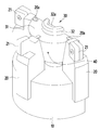
- FIG. 1 is a view schematically showing a cutter device for machining a difficult material according to the present embodiment.
- FIG. 2 is a view schematically showing the structure of a cutter device for machining a difficult material according to the present embodiment.
- FIG 3 is a view schematically showing the outside of the cutter apparatus for machining a difficult material according to the present embodiment.
- FIG. 4 is a view schematically showing an angle adjusting unit of the cutter apparatus for machining a difficult material according to the present embodiment.
- FIG. 1 is a view schematically showing a cutter device for machining a difficult material according to the present embodiment.
- FIG. 2 is a view schematically showing the structure of a cutter device for machining a difficult material according to the present embodiment.
- FIG 3 is a view schematically showing the outside of the cutter apparatus for machining a difficult material according to the present embodiment.
- the cutting device for cutting a difficult material As shown in Figures 1 to 3, the cutting device for cutting a difficult material according to the present embodiment, the cutting tool body 10 having a fastening portion formed in the center and at least one installed in the cutting tool body 10 While the carbide insert tip 21 is fixed to the end of the cutter 20, and the angle adjustment unit is installed in the inner space of the cutter 20 to adjust the angle by opening or closing the cutter 20 (30).
- the cutter device for cutting difficult materials can be conveniently used for machining difficult materials by adjusting the angle of the cutting carbide insert tip to change the cutting angle to achieve the optimum cutting conditions.
- the cutter is rotatably installed on the cutting tool body 10 via the hinge 22 to adjust the angle of the cutter 20 through the operation of the angle adjuster 30, the cutter ( The angle of the cemented carbide insert tip 21 fixed thereto may be adjusted through the movement of 20.
- the angle adjuster 30 further includes a wedge member 31 installed between the cutters 20 to adjust the angle of the cutter 20 according to the vertical movement amount, and the wedge member 31
- the central hole is formed in the center.
- the fastening part of the cutting tool body is provided as a screw fastening hole 10a, and the angle adjusting part 30 is screwed into the screw fastening hole 10a of the cutting tool body 10 and at the same time the wedge member ( It may further include a fixing bolt 32 is installed through the central hole of the 31.
- the angle adjuster 30 is composed of the wedge member 31 and the fixing bolt 32 is moved while the wedge member 31 is in contact with the cutter 20 through the rotation of the fixing bolt 32.
- the cutter 20 may be opened or retracted through the movement of the wedge member 31.
- the fixing bolt 32 has a tool insertion groove 32a for rotation of the fixing bolt 32 at an end thereof, and inserts a tool into the tool insertion groove 32a to fix the fixing bolt 32. By rotating, the wedge member 31 can be moved.
- the fixing bolt 32 is a structure to adjust the angle by pressing the cutter 20 by the wedge member 31 through the rotation, for example, if the fixing bolt 32 is rotated forward by the tool The wedge member 31 moves toward the cemented carbide insert tip 21 of the cutter 20 to open the cutter 20. On the contrary, when the fixing bolt 32 is reversed by a tool, the wedge member 31 is rotated. ) Can pinch the cutter 20 while moving in the direction of the cutting tool body 10.
- FIG. 4 is a view schematically showing an angle adjusting unit of the cutter apparatus for machining a difficult material according to the present embodiment.
- the wedge member 31 further includes a guide groove 31a formed along a moving direction at a side portion in contact with the cutter 20, and the cutter 20 includes the wedge member ( It may further include a guide bar (20a) is inserted into the guide groove (31a) of the guide 31.
- the cutter 20 and the wedge member 31 is a wedge member 31 is slidably assembled with respect to the cutter 20 by the coupling of the guide bar 20a and the guide groove 31a.
- the wedge member 31 slides along the cutter 20 by the rotation of the bolt 32, thereby pushing the cutter 20. Accordingly, the wedge member 31 presses the cutter 20, thereby cutting the cutter ( 20) can be opened.
- the cutter 20 may be connected to the cutting tool body 10 and the hinge 22 so that an angle thereof may be changed with respect to the cutting tool body 10.
- the wedge member 31 has a structure in which one or more fixing pins 40 are inserted in the vertical direction with respect to the fixing bolt 32 so that the rotational force of the fixing bolt 32 is transmitted to the wedge member 31.
- the wedge member 31 may be fixed through the fixing pin 40.
- the cutting angle of the cutter 20 can be easily adjusted by spreading the cutter 20 to the outside by a simple operation, and the machining of the difficult material can be conveniently performed through the angle adjustment of the cutter 20, and high hardness It is possible to prevent breakage of the cemented carbide insert tip 21 when machining a tough tough material.
Landscapes
- Engineering & Computer Science (AREA)
- Mechanical Engineering (AREA)
- Milling Processes (AREA)
- Processing Of Stones Or Stones Resemblance Materials (AREA)
Abstract
고경도 고인성의 난삭소재 가공시 초경 인서트 팁의 파손을 방지하기 위하여 난삭소재의 절삭조건에 맞춰 커터의 각도를 용이하게 조절할 수 있도록 그 중심에 체결부가 형성된 절삭용 공구 몸체; 상기 절삭용 공구 몸체에 하나 이상 설치되면서 그 단부에 초경 인서트 팁이 고정된 커터; 및 상기 커터의 내측 공간에 설치되어 커터를 벌리거나 오므림으로써 그 각도를 조절할 수 있도록 된 각도 조절부;를 포함하는 난삭소재 가공용 커터장치를 제공한다.
Description
난삭소재를 가공할 수 있는 커터장치를 개시한다.
일반적으로 인코넬, 티타늄, 고망간강 등 난삭성 소재의 절삭을 위한 커터의 경우 커터의 초경 인서트 팁이 소재의 고경도 고인성에 의해 파손되는 현상이 빈번히 발생된다.
이를 보완하기 위해 초경 공구 업체에서는 초경의 코발트양 조절로 초경 자체의 인성증가 또는 절삭인선의 변경 등으로 초경의 파손현상을 제어하고 있다. 하지만 이렇게 하더라도 고경도 고인성의 소재절삭을 위한 최적의 솔루션은 아니다.
또한, 상기 초경 인서트 팁의 경우 보통 한쪽이 마모되더라도 다른면으로 돌려서 가공을 하게 되면 4회 이상 다시 사용할 수 있는 반면, 파손이 되어버리면 바로 신규 초경 인서트 팁으로 교체해야하는 문제가 있었다.
고경도 고인성의 난삭소재 가공시 초경 인서트 팁의 파손을 방지하기 위하여 난삭소재의 절삭조건에 맞춰 커터의 각도를 용이하게 조절할 수 있도록 된 난삭소재 가공용 커터장치를 제공한다.
난삭소재 가공용 커터장치는, 그 중심에 체결부가 형성된 절삭용 공구 몸체; 상기 절삭용 공구 몸체에 하나 이상 설치되면서 그 단부에 초경 인서트 팁이 고정된 커터; 및 상기 커터의 내측 공간에 설치되어 커터를 벌리거나 오므림으로써 그 각도를 조절할 수 있도록 된 각도 조절부;를 포함한다.
상기 커터는 상기 절삭용 공구 몸체에 힌지를 매개로 회동가능하게 설치된 구조이다.
상기 각도 조절부는 상기 커터 사이에 설치되어 그 상하 이동량에 따라 커터의 각도를 조절하는 쐐기부재를 더 포함할 수 있다.
상기 쐐기부재는 그 중앙부에 중앙홀이 형성된 구조이다.
상기 절삭용 공구 몸체의 체결부는 나사체결홀로 제공되고, 상기 각도 조절부는 상기 절삭용 공구 몸체의 나사체결홀에 나사결함됨과 동시에 상기 쐐기부재의 중앙홀을 관통하여 설치되는 고정볼트를 더 포함할 수 있다.
상기 고정볼트는 그 단부에 고정볼트의 회전을 위한 공구삽입 홈이 형성된 구조이다.
상기 고정볼트는 그 회전을 통해 상기 쐐기부재가 상기 커터를 가압하여 각도를 조절하도록 하는 구조이다.
상기 쐐기부재는 상기 커터와 접하는 측면 부위에 이동방향을 따라 형성된 가이드홈을 더 포함할 수 있다.
상기 커터는 상기 쐐기부재의 가이드홈에 끼워져 안내되는 가이드 바를 더 포함할 수 있다.
상기 쐐기부재는 상기 고정볼트에 대해 수직방향으로 하나 이상의 고정핀이 삽입되어 고정볼트의 회전력이 쐐기부재에 전달되도록 하는 구조이다.
본 장치에 따르면, 간단한 조작으로 커터를 외측으로 벌려 커터의 절입각도를 용이하게 조절할 수 있고, 커터의 각도조절을 통해 난삭소재의 가공을 편리하게 진행할 수 있으며, 고경도 고인성의 난삭소재 가공시 초경팁의 파손을 방지할 수 있다.
도 1은 본 실시예에 따른 난삭소재 가공용 커터장치를 개략적으로 도시한 도면이다.
도 2는 본 실시예에 따른 난삭소재 가공용 커터장치의 구조를 개략적으로 도시한 도면이다.
도 3은 본 실시예에 따른 난삭소재 가공용 커터장치의 외측을 개략적으로 도시한 도면이다.
도 4는 본 실시예에 따른 난삭소재 가공용 커터장치의 각도 조절부를 개략적으로 도시한 도면이다.
이하에서 사용되는 전문용어는 단지 특정 실시예를 언급하기 위한 것이며, 본 발명을 한정하는 것을 의도하지 않는다. 여기서 사용되는 단수 형태들은 문구들이 이와 명백히 반대의 의미를 나타내지 않는 한 복수 형태들도 포함한다. 명세서에서 사용되는 “포함하는”의 의미는 특정 특성, 영역, 정수, 단계, 동작, 요소 및/또는 성분을 구체화하며, 다른 특정 특성, 영역, 정수, 단계, 동작, 요소, 성분 및/또는 군의 존재나 부가를 제외시키는 것은 아니다.
이하, 첨부한 도면을 참조하여, 본 발명이 속하는 기술분야에서 통상의 지식을 가진 자가 용이하게 실시할 수 있도록 본 발명의 실시예를 설명한다. 본 발명이 속하는 기술분야에서 통상의 지식을 가진 자가 용이하게 이해할 수 있는 바와 같이, 후술하는 실시예는 본 발명의 개념과 범위를 벗어나지 않는 한도 내에서 다양한 형태로 변형될 수 있다. 이에, 본 발명은 여러 가지 상이한 형태로 구현될 수 있으며 여기에서 설명하는 실시예에 한정되지 않는다.
도 1은 본 실시예에 따른 난삭소재 가공용 커터장치를 개략적으로 도시한 도면이다.
도 2는 본 실시예에 따른 난삭소재 가공용 커터장치의 구조를 개략적으로 도시한 도면이다.
도 3은 본 실시예에 따른 난삭소재 가공용 커터장치의 외측을 개략적으로 도시한 도면이다.
도 1 내지 도 3에 도시된 바와 같이, 본 실시예에 따른 난삭소재 가공용 커터장치는, 그 중심에 체결부가 형성된 절삭용 공구 몸체(10)와, 상기 절삭용 공구 몸체(10)에 하나 이상 설치되면서 그 단부에 초경 인서트 팁(21)이 고정된 커터(20) 및, 상기 커터(20)의 내측 공간에 설치되어 커터(20)를 벌리거나 오므림으로써 그 각도를 조절할 수 있도록 된 각도 조절부(30)를 포함한다.
즉, 상기 난삭소재 가공용 커터장치는 절삭용 초경 인서트 팁의 각도를 조절하여 절입각도를 변화시킴으로써 최적의 절삭조건을 갖게 하여 난삭소재의 가공에 편리하게 이용할 수 있다.
또한, 상기 커터는 상기 절삭용 공구 몸체(10)에 힌지(22)를 매개로 회동가능하게 설치되어 상기 각도 조절부(30)의 작동을 통해 커터(20)의 각도를 조절하고, 상기 커터(20)의 움직임을 통해 이에 고정된 상기 초경 인서트 팁(21)의 각도를 조절할 수 있다.
그리고, 상기 각도 조절부(30)는 상기 커터(20) 사이에 설치되어 그 상하 이동량에 따라 커터(20)의 각도를 조절하는 쐐기부재(31)를 더 포함하고, 상기 쐐기부재(31)는 그 중앙부에 중앙홀이 형성된 구조이다.
상기 절삭용 공구 몸체의 체결부는 나사체결홀(10a)로 제공되고, 상기 각도 조절부(30)는 상기 절삭용 공구 몸체(10)의 나사체결홀(10a)에 나사결함됨과 동시에 상기 쐐기부재(31)의 중앙홀을 관통하여 설치되는 고정볼트(32)를 더 포함할 수 있다.
여기서, 상기 각도 조절부(30)는 상기 쐐기부재(31)와 고정볼트(32)로 구성되어 고정볼트(32)의 회전을 통해 쐐기부재(31)가 상기 커터(20)와 접촉되면서 움직이게 되고, 상기 쐐기부재(31)의 움직임을 통해 상기 커터(20)를 벌어지게 하거나 오므리게 할 수 있다.
또한, 상기 고정볼트(32)는 그 단부에 고정볼트(32)의 회전을 위한 공구삽입 홈(32a)이 형성되고, 상기 공구삽입 홈(32a)에 공구를 삽입하여 상기 고정볼트(32)를 회전시킴으로써 상기 쐐기부재(31)를 움직이게 할 수 있다.
즉, 상기 고정볼트(32)는 그 회전을 통해 상기 쐐기부재(31)가 상기 커터(20)를 가압하여 각도를 조절하도록 하는 구조로서, 예컨대 상기 고정볼트(32)가 공구에 의해 정회전하면 상기 쐐기부재(31)가 상기 커터(20)의 초경 인서트 팁(21) 방향으로 움직이면서 커터(20)를 벌어지게 하고, 반대로 상기 고정볼트(32)가 공구에 의해 역회전하면 상기 쐐기부재(31)가 상기 절삭용 공구 몸체(10) 방향으로 움직이면서 커터(20)를 오므리게 할 수 있다.
도 4는 본 실시예에 따른 난삭소재 가공용 커터장치의 각도 조절부를 개략적으로 도시한 도면이다.
도 4에 도시된 바와 같이, 상기 쐐기부재(31)는 상기 커터(20)와 접하는 측면 부위에 이동방향을 따라 형성된 가이드홈(31a)을 더 포함하고, 상기 커터(20)는 상기 쐐기부재(31)의 가이드홈(31a)에 끼워져 안내되는 가이드 바(20a)를 더 포함할 수 있다.
여기서, 상기 커터(20)와 쐐기부재(31)는 상기 가이드 바(20a)와 가이드홈(31a)의 결합으로 쐐기부재(31)가 커터(20)에 대해 슬라이딩 가능하게 조립된 것으로, 상기 고정볼트(32)의 회전에 의해 상기 쐐기부재(31)가 커터(20)를 따라 슬라이딩되면서 커터(20)를 밀어주게 되고, 이에 따라 상기 쐐기부재(31)가 커터(20)를 가압함으로써 커터(20)가 벌어지게 할 수 있다.
상기 커터(20)는 절삭용 공구 몸체(10)와 힌지(22)로 연결되어 절삭용 공구 몸체(10)에 대해 그 각도가 변경될 수 있다.
또한, 상기 쐐기부재(31)는 상기 고정볼트(32)에 대해 수직방향으로 하나 이상의 고정핀(40)이 삽입되어 고정볼트(32)의 회전력이 쐐기부재(31)에 전달되도록 하는 구조이다. 상기 고정핀(40)을 통해 상기 쐐기부재(31)가 위치고정될 수 있다.
따라서, 간단한 조작으로 커터(20)를 외측으로 벌려 커터(20)의 절입각도를 용이하게 조절할 수 있고, 커터(20)의 각도조절을 통해 난삭소재의 가공을 편리하게 진행할 수 있으며, 고경도 고인성의 난삭소재 가공시 초경 인서트 팁(21)의 파손을 방지할 수 있다.
이상 설명한 바와 같이 본 발명의 예시적인 실시예가 도시되어 설명되었지만, 다양한 변형과 다른 실시예가 본 분야의 숙련된 기술자들에 의해 행해질 수 있을 것이다. 이러한 변형과 다른 실시예들은 첨부된 청구범위에 모두 고려되고 포함되어, 본 발명의 진정한 취지 및 범위를 벗어나지 않는다 할 것이다.
Claims (10)
- 그 중심에 체결부가 형성된 절삭용 공구 몸체;상기 절삭용 공구 몸체에 하나 이상 설치되면서 그 단부에 초경 인서트 팁이 고정된 커터; 및상기 커터의 내측 공간에 설치되어 커터를 벌리거나 오므림으로써 그 각도를 조절할 수 있도록 된 각도 조절부를 포함하는 난삭소재 가공용 커터장치.
- 제 1 항에 있어서,상기 커터는 상기 절삭용 공구 몸체에 힌지를 매개로 회동가능하게 설치된 구조의 난삭소재 가공용 커터장치.
- 제 1 항에 있어서,상기 각도 조절부는 상기 커터 사이에 설치되어 그 상하 이동량에 따라 커터의 각도를 조절하는 쐐기부재를 더 포함하는 난삭소재 가공용 커터장치.
- 제 3 항에 있어서,상기 쐐기부재는 그 중앙부에 중앙홀이 형성된 구조의 난삭소재 가공용 커터장치.
- 제 1 항 또는 제 4 항에 있어서,상기 절삭용 공구 몸체의 체결부는 나사체결홀로 제공되고,상기 각도 조절부는 상기 절삭용 공구 몸체의 나사체결홀에 나사결함됨과 동시에 상기 쐐기부재의 중앙홀을 관통하여 설치되는 고정볼트를 더 포함하는 난삭소재 가공용 커터장치.
- 제 5 항에 있어서,상기 고정볼트는 그 단부에 고정볼트의 회전을 위한 공구삽입 홈이 형성된 구조의 난삭소재 가공용 커터장치.
- 제 3 항 또는 제 5 항에 있어서,상기 고정볼트는 그 회전을 통해 상기 쐐기부재가 상기 커터를 가압하여 각도를 조절하도록 하는 구조의 난삭소재 가공용 커터장치.
- 제 3 항에 있어서,상기 쐐기부재는 상기 커터와 접하는 측면 부위에 이동방향을 따라 형성된 가이드홈을 더 포함하는 난삭소재 가공용 커터장치.
- 제 8 항에 있어서,상기 커터는 상기 쐐기부재의 가이드홈에 끼워져 안내되는 가이드 바를 더 포함하는 난삭소재 가공용 커터장치.
- 제 3 항 또는 제 5 항에 있어서,상기 쐐기부재는 상기 고정볼트에 대해 수직방향으로 하나 이상의 고정핀이 삽입되어 고정볼트의 회전력이 쐐기부재에 전달되도록 하는 구조의 난삭소재 가공용 커터장치.
Priority Applications (2)
| Application Number | Priority Date | Filing Date | Title |
|---|---|---|---|
| US16/065,758 US10576556B2 (en) | 2015-12-23 | 2016-12-21 | Cutter device for processing difficult-to-machine material |
| CN201680076155.0A CN108463304B (zh) | 2015-12-23 | 2016-12-21 | 用于加工难切削材料的刀具装置 |
Applications Claiming Priority (2)
| Application Number | Priority Date | Filing Date | Title |
|---|---|---|---|
| KR10-2015-0185434 | 2015-12-23 | ||
| KR1020150185434A KR101672298B1 (ko) | 2015-12-23 | 2015-12-23 | 난삭소재 가공용 커터장치 |
Publications (1)
| Publication Number | Publication Date |
|---|---|
| WO2017111474A1 true WO2017111474A1 (ko) | 2017-06-29 |
Family
ID=57571381
Family Applications (1)
| Application Number | Title | Priority Date | Filing Date |
|---|---|---|---|
| PCT/KR2016/015041 Ceased WO2017111474A1 (ko) | 2015-12-23 | 2016-12-21 | 난삭소재 가공용 커터장치 |
Country Status (4)
| Country | Link |
|---|---|
| US (1) | US10576556B2 (ko) |
| KR (1) | KR101672298B1 (ko) |
| CN (1) | CN108463304B (ko) |
| WO (1) | WO2017111474A1 (ko) |
Families Citing this family (2)
| Publication number | Priority date | Publication date | Assignee | Title |
|---|---|---|---|---|
| CN111590124B (zh) * | 2020-05-25 | 2022-05-20 | 芜湖市零一精密工具制造有限公司 | 一种便于调节的铣刀 |
| CN116638152B (zh) * | 2023-06-15 | 2024-08-13 | 易优创(苏州)精密工具有限公司 | 一种可调式铰刀 |
Citations (5)
| Publication number | Priority date | Publication date | Assignee | Title |
|---|---|---|---|---|
| JPS6232719U (ko) * | 1985-08-12 | 1987-02-26 | ||
| KR20120043746A (ko) * | 2009-07-26 | 2012-05-04 | 이스카 엘티디. | 절삭 인서트 및 회전형 절삭 공구 |
| KR20130130145A (ko) * | 2012-02-14 | 2013-12-02 | 박시두 | 밀링커터의 각도조절장치 |
| KR20150058976A (ko) * | 2013-11-21 | 2015-05-29 | 두산중공업 주식회사 | 튜브 폼 커터 |
| KR101534441B1 (ko) * | 2014-04-09 | 2015-07-07 | 강원대학교산학협력단 | 버 제거장치 |
Family Cites Families (23)
| Publication number | Priority date | Publication date | Assignee | Title |
|---|---|---|---|---|
| GB191120949A (en) * | 1911-09-22 | 1912-06-27 | Frederick Price | Improvements in Adjustable Reamers, Taps, and the like. |
| US2138727A (en) * | 1936-04-06 | 1938-11-29 | Stuart A Cogsdill | Cutting tool |
| GB552973A (en) * | 1942-06-12 | 1943-05-03 | Samuel Alexander Fox | Improvements in or relating to adjustable reamers |
| US2359296A (en) * | 1942-07-04 | 1944-10-03 | Wilson C Broga | Adjustable reamer |
| US2791946A (en) * | 1952-10-31 | 1957-05-14 | Cincinnati Milling Machine Co | Variable conical cutter |
| US2712686A (en) * | 1954-05-18 | 1955-07-12 | Ex Cell O Corp | Adjustable tool construction |
| US3380137A (en) * | 1966-05-12 | 1968-04-30 | Valeron Corp | Cylindrical insert cutting tool |
| GB1160425A (en) * | 1966-07-20 | 1969-08-06 | Marsh Brothers & Co Ltd | Improvements in or relating to Cutting Tools. |
| US3664755A (en) * | 1970-12-02 | 1972-05-23 | Singer Co | Finishing boring head |
| SU1537424A1 (ru) * | 1987-07-20 | 1990-01-23 | Краматорский Научно-Исследовательский И Проектно-Технологический Институт Машиностроения | Регулируема развертка |
| JP3415111B2 (ja) * | 2000-10-17 | 2003-06-09 | 大充男 井上 | 研磨工具 |
| ATE409536T1 (de) | 2006-02-13 | 2008-10-15 | Kaiser Heinz Ag | Werkzeug für die spahnabhebende bearbeitung |
| CN201338126Y (zh) * | 2009-01-12 | 2009-11-04 | 广西玉柴机器股份有限公司 | 一种可微调铣刀 |
| KR100919628B1 (ko) | 2009-03-23 | 2009-09-30 | 임사인 | 초경팁이 구비된 굴착면의 확장 및 축소가 가능한 직천공장치용 천공비트 |
| KR20120016255A (ko) * | 2009-04-28 | 2012-02-23 | 다이아몬드 이노베이션즈, 인크. | 물품을 부착시키거나 부착을 개선시키는 방법 |
| DE102009023290A1 (de) * | 2009-05-29 | 2010-12-02 | Muth, Dieter | Einstellbare Reibahle mit mechanisch spürbarer definierter Rasterung |
| DE102010014186A1 (de) | 2010-04-03 | 2011-10-06 | Gühring Ohg | Rotierbares Schneidwerkzeug |
| US9586274B2 (en) * | 2011-06-27 | 2017-03-07 | Walter Ag | Cubic cutting insert for boring or plunging |
| US20130343826A1 (en) * | 2012-06-25 | 2013-12-26 | Steven Webb | Cutting tool insert with powder metal insert body |
| KR101555305B1 (ko) | 2013-12-12 | 2015-10-06 | 두산중공업 주식회사 | 회전 절삭 공구 및 그 제조 방법 |
| DE102014105311A1 (de) * | 2013-12-17 | 2015-06-18 | Ergosurg Gmbh | Verfahren und System zur steuerbaren Verstellung der Abtragsleistung von handgeführten material- und gewebetrennenden Werkzeugen und Effektoren |
| US10183347B2 (en) * | 2015-09-08 | 2019-01-22 | Iscar, Ltd. | Rotary cutting tool having axial position adjustment arrangement |
| DE102016111805A1 (de) * | 2016-06-28 | 2017-12-28 | Komet Group Gmbh | Spanabhebendes Maschinenwerkzeug, insbesondere Maschinenreibwerkzeug |
-
2015
- 2015-12-23 KR KR1020150185434A patent/KR101672298B1/ko active Active
-
2016
- 2016-12-21 CN CN201680076155.0A patent/CN108463304B/zh active Active
- 2016-12-21 WO PCT/KR2016/015041 patent/WO2017111474A1/ko not_active Ceased
- 2016-12-21 US US16/065,758 patent/US10576556B2/en active Active
Patent Citations (5)
| Publication number | Priority date | Publication date | Assignee | Title |
|---|---|---|---|---|
| JPS6232719U (ko) * | 1985-08-12 | 1987-02-26 | ||
| KR20120043746A (ko) * | 2009-07-26 | 2012-05-04 | 이스카 엘티디. | 절삭 인서트 및 회전형 절삭 공구 |
| KR20130130145A (ko) * | 2012-02-14 | 2013-12-02 | 박시두 | 밀링커터의 각도조절장치 |
| KR20150058976A (ko) * | 2013-11-21 | 2015-05-29 | 두산중공업 주식회사 | 튜브 폼 커터 |
| KR101534441B1 (ko) * | 2014-04-09 | 2015-07-07 | 강원대학교산학협력단 | 버 제거장치 |
Also Published As
| Publication number | Publication date |
|---|---|
| US10576556B2 (en) | 2020-03-03 |
| US20190009350A1 (en) | 2019-01-10 |
| KR101672298B1 (ko) | 2016-11-03 |
| CN108463304B (zh) | 2020-06-09 |
| CN108463304A (zh) | 2018-08-28 |
Similar Documents
| Publication | Publication Date | Title |
|---|---|---|
| EP2834032B1 (en) | Cutting tool and cutting head with a resilient coupling portion | |
| KR101513764B1 (ko) | 공구, 공구 본체 및 절삭 헤드 | |
| EP2988896B1 (en) | Tool holder having a clamping member with a non-circular cross-section and method for clamping a cutting insert therein | |
| CN104588739B (zh) | 一种旋转加工刀具 | |
| CN101678486B (zh) | 可扩张式铰刀 | |
| CN107000074B (zh) | 使孔锯可释放地联接到钻轴的系统 | |
| WO2017111474A1 (ko) | 난삭소재 가공용 커터장치 | |
| US20150273591A1 (en) | Boring tool | |
| KR101800614B1 (ko) | 에어 척 죠의 스트로크위치 감지를 위한 감지구용 위치 조절장치 | |
| US20070053753A1 (en) | Boring head | |
| EP3045264B1 (en) | Processing device | |
| EP3329096B1 (en) | Cutting bit assembly | |
| US8590125B2 (en) | Device for cutting and burnishing a surface of a work piece | |
| EP3753698A1 (en) | Drilling device for enlarged-diameter hole | |
| WO2006089117B1 (en) | Self-centering drill bit chuck | |
| CN105817707A (zh) | 带有内部冷却的小型化的去毛刺和/或倒角工具 | |
| KR20070024662A (ko) | 연삭기 내에서 기계 가공되는 부품을 고정하기 위한 포인팅스테디레스트 클램프 | |
| US10052780B2 (en) | Hydraulic punch machine, and punch carrier for a punch machine | |
| CA2699351C (en) | Axial seating pin | |
| KR101672297B1 (ko) | 난삭소재 가공용 커터장치 | |
| KR102100471B1 (ko) | 직경 조절형 리머 | |
| CN101133230B (zh) | 钻杆支承件 | |
| US20240269805A1 (en) | Wrench with over-center jaws | |
| US10612314B2 (en) | Gearbox guide assembly | |
| CN215786949U (zh) | 一种高硬度钻孔加工用钻头 |
Legal Events
| Date | Code | Title | Description |
|---|---|---|---|
| 121 | Ep: the epo has been informed by wipo that ep was designated in this application |
Ref document number: 16879341 Country of ref document: EP Kind code of ref document: A1 |
|
| NENP | Non-entry into the national phase |
Ref country code: DE |
|
| 122 | Ep: pct application non-entry in european phase |
Ref document number: 16879341 Country of ref document: EP Kind code of ref document: A1 |