WO2017111013A1 - ベーン型圧縮機 - Google Patents
ベーン型圧縮機 Download PDFInfo
- Publication number
- WO2017111013A1 WO2017111013A1 PCT/JP2016/088363 JP2016088363W WO2017111013A1 WO 2017111013 A1 WO2017111013 A1 WO 2017111013A1 JP 2016088363 W JP2016088363 W JP 2016088363W WO 2017111013 A1 WO2017111013 A1 WO 2017111013A1
- Authority
- WO
- WIPO (PCT)
- Prior art keywords
- vane
- pressure chamber
- back pressure
- chamber
- rotor
- Prior art date
- Legal status (The legal status is an assumption and is not a legal conclusion. Google has not performed a legal analysis and makes no representation as to the accuracy of the status listed.)
- Ceased
Links
Images




Classifications
-
- F—MECHANICAL ENGINEERING; LIGHTING; HEATING; WEAPONS; BLASTING
- F04—POSITIVE - DISPLACEMENT MACHINES FOR LIQUIDS; PUMPS FOR LIQUIDS OR ELASTIC FLUIDS
- F04C—ROTARY-PISTON, OR OSCILLATING-PISTON, POSITIVE-DISPLACEMENT MACHINES FOR LIQUIDS; ROTARY-PISTON, OR OSCILLATING-PISTON, POSITIVE-DISPLACEMENT PUMPS
- F04C18/00—Rotary-piston pumps specially adapted for elastic fluids
- F04C18/30—Rotary-piston pumps specially adapted for elastic fluids having the characteristics covered by two or more of groups F04C18/02, F04C18/08, F04C18/22, F04C18/24, F04C18/48, or having the characteristics covered by one of these groups together with some other type of movement between co-operating members
- F04C18/34—Rotary-piston pumps specially adapted for elastic fluids having the characteristics covered by two or more of groups F04C18/02, F04C18/08, F04C18/22, F04C18/24, F04C18/48, or having the characteristics covered by one of these groups together with some other type of movement between co-operating members having the movement defined in group F04C18/08 or F04C18/22 and relative reciprocation between the co-operating members
- F04C18/344—Rotary-piston pumps specially adapted for elastic fluids having the characteristics covered by two or more of groups F04C18/02, F04C18/08, F04C18/22, F04C18/24, F04C18/48, or having the characteristics covered by one of these groups together with some other type of movement between co-operating members having the movement defined in group F04C18/08 or F04C18/22 and relative reciprocation between the co-operating members with vanes reciprocating with respect to the inner member
-
- F—MECHANICAL ENGINEERING; LIGHTING; HEATING; WEAPONS; BLASTING
- F04—POSITIVE - DISPLACEMENT MACHINES FOR LIQUIDS; PUMPS FOR LIQUIDS OR ELASTIC FLUIDS
- F04C—ROTARY-PISTON, OR OSCILLATING-PISTON, POSITIVE-DISPLACEMENT MACHINES FOR LIQUIDS; ROTARY-PISTON, OR OSCILLATING-PISTON, POSITIVE-DISPLACEMENT PUMPS
- F04C29/00—Component parts, details or accessories of pumps or pumping installations, not provided for in groups F04C18/00 - F04C28/00
Definitions
- the present invention relates to a vane type compressor provided with a vane having a structure useful for coping with problems caused by compressing oil accumulated in a back pressure chamber at the bottom of the vane groove.
- Patent Document 1 Japanese Patent Application Laid-Open No. 57-26293 discloses a compression chamber in which a rotor provided with a vane is arranged in a chamber composed of a cylinder and side blocks provided on both sides thereof, and the rotor rotates.
- a vane type compressor that compresses by expanding or contracting, low pressure pressure is guided into the vane pressing chamber formed by the lower end of the vane and a groove formed in the rotor during the suction stroke, and the vane pressing chamber is shut off during the compression stroke.
- a vane type compressor is disclosed in which when the compressed fluid from the compression chamber is discharged from the discharge hole, the vane pressing chamber opens to the high pressure side or the low pressure side to release the pressure in the vane pressing chamber.
- Patent Document 1 As a countermeasure against this, in Patent Document 1, the back pressure chamber is made an independent space in the compression stroke, and the pressure of the back pressure chamber is increased against the drawing of the vane. I am doing so.
- the vane type compressor that confins the back pressure chamber in this way, when the ratio of liquid such as oil in the back pressure chamber is large, the pressure becomes too large due to liquid compression by the vane, There were problems such as increased sliding friction at the tip of the vane and a lower coefficient of performance.
- Patent Document 2 Japanese Utility Model Publication No. 02-204708 configures a compressor body by fixing side blocks on both sides of a cylinder, and arranges a rotor in which vanes are inserted and inserted in the compressor body.
- a vane type compressor that constitutes a back pressure chamber surrounded by a rotor, a vane, and a side block, and this back pressure chamber becomes an independent space in the compression stroke, the back pressure chamber communicates with the side block in the compression stroke.
- a vane compressor having a blind hole for a damper.
- the vane in the compression stroke, the vane is gradually pushed into the vane groove along the inner surface of the cylinder to reduce the volume of the back pressure chamber.
- the pressure in the back pressure chamber escapes to the damper blind hole and the pressure in the back pressure chamber is prevented from rising abnormally.
- Patent Document 3 Japanese Patent Application Laid-Open No. 09-329094 describes a back pressure groove that communicates with the vane back pressure chamber in the entire section until the tip of the vane reaches the vicinity of the suction port start end, and oil in the back pressure chamber.
- a control oil pressure chamber that communicates with the high pressure chamber via the first passage, and communicates with the vane back pressure chamber in the section from the vicinity of the discharge port start end to the suction port start end.
- the second passage for releasing the high-pressure vane back pressure to the control pressure chamber is connected to the both passages via the control pressure chamber when the discharge pressure is lower than a predetermined value, and when the discharge pressure is higher than the predetermined value,
- a vane compressor that includes a spool valve that blocks communication.
- the present invention provides a vane type compressor having a vane having a structure capable of effectively avoiding an abnormal pressure increase in the back pressure chamber due to compression of the liquid accumulated in the back pressure chamber of the vane. It is to provide.
- the present invention provides a housing, a cylinder portion provided with a cam surface and provided in the housing, and a pair of side block portions that close both ends in the axial direction of the cylinder portion, A drive shaft rotatably supported by the pair of side block portions; a rotor fixed to the drive shaft and rotatably accommodated in the cylinder portion; and a plurality of vane grooves formed in the rotor; A plurality of vanes that are slidably inserted into the vane grooves and have tip portions protruding and retracting from the vane grooves and sliding on the cam surface; a back pressure chamber located at the bottom of the vane grooves; and the cylinder portion; In a space closed by the pair of side block portions, a compression chamber formed by the rotor and the vane, a suction port for sucking fluid into the compression chamber, and before being compressed in the compression chamber A discharge port that discharges fluid; a high-pressure chamber that stores fluid discharged from the discharge port; an oil reservoir
- the recess structure is preferably a notch formed between both side end portions of the vane bottom surface portion in the axial direction, and is formed at both side end portions in the axial direction of the bottom surface portion of the vane. It can be a notch.
- the dent structure is a notch formed between both side ends of the bottom surface of the vane in the axial direction and on one side in the thickness direction of the vane.
- the said recessed structure may be a notch part formed in the one side of the thickness direction of the said vane over the full length of the axial direction of the said vane bottom face part.
- the recess structure is a notch formed on the opposite side of the moving direction of the vane by the rotation of the rotor.
- the concave structure is a groove portion having a predetermined depth formed in a central portion in the thickness direction of the vane between both end portions of the vane bottom surface portion in the axial direction.
- the vane compressor is provided with a second communication passage that connects the back pressure chamber and the high pressure chamber in a closed section in which communication between the recess and the back pressure chamber is closed. Accordingly, oil in the back pressure chamber can be released to the high pressure chamber in a closed section where communication between the recess and the back pressure chamber is closed.
- the back pressure chamber and the second communication path are formed by the notch portions formed at both end portions in the axial direction of the vane bottom surface portion or over the entire axial length of the vane bottom surface portion. Since the area of the opening is sufficiently secured, oil can be efficiently released to the high pressure chamber, and an abnormal increase in the pressure of the back pressure chamber can be suppressed.
- the recess structure for enlarging the volume of the back pressure chamber at the bottom surface of the vane, the compressibility of the oil in the back pressure chamber by the vane is achieved. Is reduced, and an abnormal increase in the pressure of the back pressure chamber can be prevented.
- the recessed structure is formed at both end portions of the vane bottom surface portion, or is formed in the entire axial direction of the vane bottom surface portion, thereby opening the back pressure chamber and the second communication path. Is sufficiently secured and oil can be discharged efficiently, so that an abnormal increase in the pressure in the back pressure chamber can be prevented.
- FIG. 1 is a side sectional view of a vane type compressor according to the present invention.
- FIG. 2 is a front sectional view of the vane type compressor shown in FIG.
- FIG. 3 is an explanatory view showing the vane according to the first embodiment used in the vane type compressor shown in FIG. 1, wherein (a) is a front view thereof and (b) is a side view thereof.
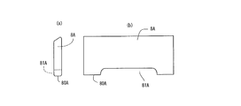
- FIG. 4 is an explanatory view showing a vane according to a second embodiment used in the vane type compressor shown in FIG. 1, wherein (a) is a front view thereof and (b) is a side view thereof.
- FIG. 5 is an explanatory view showing a vane according to a third embodiment used in the vane type compressor shown in FIG.
- FIG. 6 is an explanatory view showing a vane according to a fourth embodiment used in the vane type compressor shown in FIG. 1, wherein (a) is a front view thereof and (b) is a side view thereof.
- FIG. 7 is an explanatory view showing a vane according to a fifth embodiment used in the vane type compressor shown in FIG. 1, wherein (a) is a front view thereof and (b) is a side view thereof.
- FIG. 8 is an explanatory view showing a vane according to a sixth embodiment used in the vane type compressor shown in FIG. 1, wherein (a) is a front view thereof and (b) is a side view thereof.
- FIG. 6 is an explanatory view showing a vane according to a fourth embodiment used in the vane type compressor shown in FIG. 1, wherein (a) is a front view thereof and (b) is a side view thereof.
- FIG. 7 is an explanatory view showing a vane according to a fifth embodiment used in the vane type compressor shown in FIG
- FIG. 9 is an explanatory view showing a vane according to a seventh embodiment used in the vane type compressor shown in FIG. 1, wherein (a) is a front view thereof and (b) is a side view thereof.
- FIG. 10 is an explanatory view showing a vane according to an eighth embodiment used in the vane type compressor shown in FIG. 1, wherein (a) is a front view thereof and (b) is a side view thereof.
- FIG. 11 is an explanatory view showing a communication state between the high-pressure gas introduction hole and the back pressure chamber.
- FIG. 12 is an explanatory diagram illustrating a load related to the vane and the vane groove.
- the vane compressor 1 includes a cylinder block 3 in which a cylinder portion 3a in which a cam surface 2 is formed and a rear side block portion 3b that closes one end of the cylinder portion 3a are integrally formed. 3 and a housing 4 in which a front side block 4b and a shell forming portion 4a are integrally formed and closes the other end of the cylinder 3a, and one end is on the rear side block 3b.
- a drive shaft 5 that is rotatably supported by the front side block 4b, a rotor 6 that is fixed to the drive shaft 5 and rotates as the drive shaft 5 rotates, and that the rotor 6 is circumferentially equidistant.
- a discharge chamber 12 defined between them and communicating with the compression chamber 9 via the discharge port 11 is provided. Further, the discharge port 11 is provided with a discharge valve 13, and the communication between the discharge port 11 and the discharge chamber 12 is opened and closed.
- a back pressure chamber 70 facing the vane bottom surface portion 80 is formed at the lower end portion of the vane groove 7.
- a high-pressure chamber 14 is formed at the upper portion thereof, and an oil reservoir chamber 15 is formed at the lower portion thereof.
- the side block portions 3b and 4b are formed with a recess 16 through which the back pressure chamber 70 communicates in a stroke in which the tip of the vane is in front of the discharge port from the suction port.
- the recess 16 receives oil from the oil reservoir chamber 18 in which oil separated from the working fluid by an oil separator (not shown) (having a pressure corresponding to the pressure of the discharge gas) is accumulated. Is supplied via a communication path).
- the rear side block 3b is provided with a high-pressure gas introduction hole 18a that communicates with the back pressure chamber 70 in a closed section in which communication between the recess 16 and the back pressure chamber 70 is closed. . Further, a high-pressure gas introduction path 18 (second communication path) that communicates the high-pressure gas introduction hole 18a and the high-pressure chamber 14 is provided.
- the back pressure chamber 70 communicates with the high pressure chamber 14 via the high pressure gas introduction hole 18a and the high pressure gas introduction passage 18 (second communication passage).
- the vane 8 is a recess for expanding the volume of the back pressure chamber 70 in an intermediate portion in the axial direction of the vane bottom surface portion 80 as shown in FIG.
- the structure has an intermediate cutout portion 81, and end cutout portions 82 and 83 are formed at both axial ends of the vane bottom surface portion 80.
- oil in the back pressure chamber 70 is compressed by the vane 8 that enters the back pressure chamber 70 from the vane groove 7 in the compression stroke, but the back pressure is reduced by the intermediate notch 81 and the end notches 82 and 83. Since the volume of the chamber 70 is increased as compared with the case where the notched portions 81, 82, 83 are not provided, the oil compression rate is reduced and the pressure of the back pressure chamber 70 can be prevented from becoming abnormally high. .
- the back pressure chamber 70 and the high pressure gas introduction hole 18a are communicated to introduce high pressure gas into the back pressure chamber 70, so that the tip of the vane 8 is securely attached to the cam surface 2. I try to make it slide.
- the pressure in the back pressure chamber 70 becomes too high, the pressure in the back pressure chamber 70 increases by releasing high pressure oil to the high pressure chamber 14 through the high pressure gas introduction hole 18 a and the high pressure gas introduction path 18. Can be suppressed.
- FIG. 11 in the case of the conventional vane, since the lower end portion of the vane 8 enters the back pressure chamber 70, there arises a problem that the opening 18b of the high pressure gas introduction hole 18a becomes very narrow.
- one cutout portion 83 ensures a sufficient area of the opening 18b with respect to the high pressure gas introduction hole 18a. Further, the other notch portion 82 is formed for weight balance with the one notch portion 83.
- the intermediate cutout 81 described above may be either an arch shape or a square shape.
- the vane 8A according to the second embodiment shown in FIG. 4 does not form the end cutout portions 82 and 83 but forms the intermediate cutout portion 81A larger than the vane 8 according to the first embodiment described above. It is a thing.
- the intermediate notch 81A may be arched or rectangular. Further, the second embodiment is characterized in that the intermediate notch 81A is formed in a sufficient size.
- the vane 8B according to the third embodiment shown in FIG. 5 is characterized in that a plurality of intermediate notches 81B are provided with respect to the vane 8 according to the first embodiment described above.
- a plurality of intermediate notches 81B are provided with respect to the vane 8 according to the first embodiment described above.
- the reinforcing portion 84B it is possible to form the reinforcing portion 84B for maintaining the strength between the intermediate notches 81B. For this reason, the intensity
- the vane 8C according to the fourth embodiment shown in FIG. 6 is provided with only the end cutout portions 82C and 83C without forming the intermediate cutout portion 81 with respect to the vane 8 according to the first embodiment described above. It is characterized by.
- the volume of the back pressure chamber 70 can be increased by the end cutout portions 82C and 83C, and further, for example, the one end cutout portion 83C can be used to connect the back pressure chamber 70 and the high pressure gas introduction hole 18a. Since the area of the opening 18b is sufficiently secured, an abnormal increase in the pressure of the back pressure chamber 70 can be suppressed or prevented.
- the vane 8D according to the fifth embodiment shown in FIG. 7 has a one-side notch 85D cut out on one side in the thickness direction of the vane 8D along the axial direction of the vane bottom surface portion 80D.
- the volume of the back pressure chamber 70 can be secured by the one-side cutout portion 85D, and the back pressure chamber 70 and the high-pressure gas introduction hole 18a are formed by one end portion of the one-side cutout portion 85D. Since the area of the opening 18b is sufficiently secured, an abnormal increase in the pressure of the back pressure chamber 70 can be suppressed or prevented.
- the one-side notch 85D is formed on the opposite side of the direction in which the vane 8D moves due to the rotation of the rotor 6. As shown in FIG. 12, when the rotor 6 rotates in the direction indicated by A, a force in the direction indicated by B acts on the vane 8 due to the compression reaction force, and between the vane groove 7 and the vane 8. Since there is a sliding clearance, the vane groove 7 and the vane 8 come into contact at the contact portions 87 and 88.
- the one-side cutout portion 85D is formed on the front side in the direction in which the vane moves, the length in which the vane 8 contacts the inner wall of the vane groove 7 in the axial direction of the contact portion 87 is shortened. This causes a problem that the vane groove 7 or the vane 8 of the rotor 6 is easily worn.
- the one-side cutout portion 85D is formed on the opposite side of the direction in which the vane moves, so the axial contact length of the contact portion 87 is not shortened, An increase in the contact pressure between the vane 8 and the vane groove 7 can be avoided.
- the rotor 6 is formed of an aluminum material and the vane 8 is formed of a sintered iron material, and the rotor side (vane groove side) is easily worn.
- the axial contact length is increased. An increase in local contact pressure can be suppressed, and wear can be avoided.
- the vane 8E according to the sixth embodiment shown in FIG. 8 is partially cut on one side of the vane bottom surface portion 80E in a predetermined range of the intermediate portion along the axial direction and cut out on one side in the thickness direction of the vane 8E. It has the notch part 85E.
- the vane 8E according to the sixth embodiment has a shape in which both sides of the one-side partially cut-out portion 85E are closed. Since both ends serve as reinforcing columns, the back pressure chamber 70 is used. It is possible to maintain a sufficient strength of the vane while securing the volume.
- the one-side partially cutout portion 85E is formed on the opposite side of the moving direction of the vane.
- the contact length in the axial direction of 87 is not shortened, and the contact pressure between the vane 8 and the vane groove 7 can be avoided from increasing.
- the rotor side in the rotor 6 made of aluminum and the vane 8 made of a sintered material, the rotor side (vane groove side) is likely to be worn. As described above, by increasing the contact length in the axial direction, it is possible to suppress an increase in local contact pressure and to avoid wear.
- the vane 8F according to the seventh embodiment shown in FIG. 9 has a plurality of partially cut-out portions 85F on one side cut out at a predetermined interval along the axial direction of the vane bottom surface portion 80F.
- the portion between the one-side partially cutout portions 85F and both ends thereof serve as reinforcing columns.
- the one-side partially cut-out portion 85F is formed on the side opposite to the moving direction of the vane.
- the contact length in the axial direction of 87 is not shortened, and the contact pressure between the vane 8 and the vane groove 7 can be avoided from increasing. Also in this Example 7, as in the case of Example 5 described above, in the rotor 6 made of aluminum and the vane 8 made of a sintered material, the rotor side (vane groove side) is likely to be worn. As described above, by increasing the contact length in the axial direction, it is possible to suppress an increase in local contact pressure and to avoid wear.
- the vane 8G according to the eighth embodiment illustrated in FIG. 10 is a groove portion 86G having a predetermined depth from the vane bottom surface portion 80G in the intermediate portion in the axial direction of the vane bottom surface portion 80G and in the intermediate portion in the thickness direction of the vane 8G. Is formed.
- the volume of the back pressure chamber 70 can be expanded by the groove portion 86G having a predetermined depth, and the periphery of the groove portion 86G is surrounded by the wall portion, so that the strength of the vane bottom surface portion 80G is increased. It can be maintained.
- the vanes 8, 8A to 8G according to the present invention have a structure in which the volume of the back pressure chamber 70 formed in the rotor 6 is increased. It can be solved. Further, in the vanes 8, 8C, 8D according to the present invention, since the area of the opening 18b between the back pressure chamber 70 and the high pressure gas introduction hole 18a is sufficiently secured, the pressure in the back pressure chamber 70 is abnormally increased. Can be suppressed or prevented.
Landscapes
- Engineering & Computer Science (AREA)
- Mechanical Engineering (AREA)
- General Engineering & Computer Science (AREA)
- Rotary Pumps (AREA)
Abstract
【課題】 本発明は、ベーンの背圧室に溜まった液体を圧縮することによる背圧室の異常な圧力上昇を効果的に避けることが可能な構造を有するベーンを具備したベーン型圧縮機を提供する。 【解決手段】 本発明は、シリンダ部3a内周面との間に圧縮空間を画成するロータ6に形成された複数のベーン溝7にそれぞれ摺動自在に挿通され、ベーン溝7の底部に位置する背圧室70の圧力によって先端部が前記シリンダ部2内周面に押圧され、前記背圧室70と対峙するベーン底面部80に、前記背圧室70の容積を拡大するための凹み構造が形成されることものである。
Description
本発明は、ベーン溝底部の背圧室に溜まったオイルを圧縮することによる不都合に対処するために有用な構造を有するベーンを具備したベーン型圧縮機に関する。
特許文献1(特開昭57-26293号公報)は、シリンダとその両側に設けられたサイドブロックとよりなる室内に、ベーンが設けられたロータを配して、ロータが回転することで圧縮室が拡大又は縮小して圧縮作用を行うベーン型圧縮機において、吸入行程時には低圧圧力をベーンの下端とロータに形成された溝とよりなるベーン押圧室内に導き、圧縮行程時にはベーン押圧室を遮断し、圧縮室からの圧縮流体が吐出孔から吐出されるとベーン押圧室が高圧側又は低圧側に開口してベーン押圧室内の圧力を逃がすようにしたベーン型圧縮機を開示する。
従来のベーン型圧縮機において、ベーンは、その先端が常にシリンダの内面に沿って回転して圧縮室のシールを行う必要があるので、ベーンの遠心力に加えて、ベーンの後端とベーンが嵌挿されたベーン溝との間に背圧室を形成し、この背圧室に高圧を導き、ベーンを半径方向に押し出すようになっている。従来、前記背圧室の圧力は、一定に保つようにしていたが、圧縮行程時において、該圧力が不足してベーンがロータ面から中心方向へ引っ込み、再びシリンダの内面に当たり、異音を発生するいわゆるベーンチャッタリングを起こすことが知られており、この対策として、特許文献1では、背圧室を圧縮行程で独立空間とし、ベーンが引き込むのに対抗して背圧室の圧力を上昇させるようにしている。しかしながら、このように背圧室を閉じ込める形式のベーン型圧縮機においては、背圧室のオイル等の液分の割合が多い場合には、ベーンによる液圧縮となって前記圧力が大きくなりすぎ、ベーンの先端の摺動摩擦が増大し、成績係数が低くなる等の不具合があった。
そこで、特許文献2(実公平02-20478号公報)は、シリンダの両側にサイドブロックを固定して圧縮機本体を構成し、この圧縮機本体内にベーンが嵌挿されたロータを配置し、ロータ、ベーン及びサイドブロックに囲まれた背圧室を構成し、この背圧室が圧縮行程で独立した空間となるベーン型圧縮機において、前記サイドブロックに前記圧縮行程において背圧室が連通するダンパ用盲孔を形成したベーン型圧縮機を開示する。この特許文献2に開示されるベーン型圧縮機においては、圧縮行程において、ベーンがシリンダの内面に沿って徐々にベーン溝内方に押し込まれ背圧室の容積が減少する一方で、背圧室がダンパ用盲孔に開口して背圧室の圧力がダンパ用盲孔に逃げるので、背圧室の圧力が異常に上昇することを防止するようにしたものである。
また、特許文献3(特開平09-329094号公報)は、ベーンの先端が吸入ポート始端部付近に達するまでの全区間でベーン背圧室と連通する背圧溝と、オイルを背圧室に供給するオイル通路とを備え、第1通路を介して高圧室と連通した制御圧室と、ベーン先端が吐出ポート始端部付近から吸入ポート始端部付近に達するまでの区間でベーン背圧室と連通して高圧のベーン背圧を制御圧室に逃がす第2通路と、吐出圧が所定値以下のとき両通路を制御圧室を介して連通させるとともに、吐出圧が所定値より大きいとき両通路の連通を遮断するスプール弁とを備えるベーン圧縮機を開示する。これによって、オイルの供給量が多い低負荷時、両通路が制御圧室を介して連通し、ベーン先端が吐出ポート始端部付近から吸入ポート始端部付近に達するまでの区間におけるベーン背圧室内でのオイル圧縮が防止されるものである。
しかしながら、特許文献2に開示された構成においては、サイドブロック形成部のロータの端面と対峙する面の背圧閉鎖区間にダンパ用盲孔を設けることで対応しているので、盲孔の限られた空間の分だけしか背圧室の圧力を逃がすことができず、背圧室の異常な圧力上昇を十分に防ぐことができないものであった。
また、特許文献3に開示された構成においては、スプール弁によってオイルの供給量が多い低負荷時に、第1及び第2の通路が制御圧室を介して連通することから、ベーン先端が吐出ポート始端部付近から吸入ポート始端部付近に達するまでの区間におけるベーン背圧室内でのオイル圧縮が防止されるが、構造が複雑であるという問題がある。
このため、本発明は、ベーンの背圧室に溜まった液体を圧縮することによる背圧室の異常な圧力上昇を効果的に避けることが可能な構造を有するベーンを具備したベーン型圧縮機を提供するものである。
上記課題を達成するために、本発明は、ハウジングと、カム面が形成され、前記ハウジング内に設けられたシリンダ部と、前記シリンダ部の軸方向の両端を閉塞する一対のサイドブロック部と、前記一対のサイドブロック部に回転自在に支持された駆動軸と、前記駆動軸に固装されて前記シリンダ部内に回転可能に収容されるロータと、前記ロータに形成された複数のベーン溝と、前記ベーン溝に摺動自在に挿入され、先端部が前記ベーン溝から出没して前記カム面を摺動する複数のベーンと、前記ベーン溝の底部に位置する背圧室と、前記シリンダ部と前記一対のサイドブロック部とにより閉塞された空間に、前記ロータと前記ベーンによって形成される圧縮室と、前記圧縮室に流体を吸入する吸入ポートと、前記圧縮室で圧縮された前記流体を吐出する吐出ポートと、前記吐出ポートから吐出された流体を収容する高圧室と、吐出された前記流体の圧力に相当する圧力のオイルを貯留するオイル溜まり室と、少なくとも一方の前記サイドブロック部の前記圧縮室側端面に形成され、前記ベーンの先端部が前記吸入ポートから前記吐出ポートの手前にある行程において、前記背圧室と連通する凹部と、前記凹部と前記オイル溜まり室とを連通する第1の連通路と、を備えたベーン型圧縮機において、前記背圧室と対峙する前記ベーンのベーン底面部に、前記背圧室の容積を拡大するための凹み構造が形成されていることにある。
これによって、ベーンがロータの回転とともにベーン溝の底部に位置する背圧室に押し込まれた背圧室の圧力が上昇するが、ベーンの底面部に背圧室の容積を拡大するための凹み構造が形成されていることから、ベーンによる背圧室の圧縮率を低減することができるため、背圧室の異常な圧力上昇を防止できるものである。
また、前記凹み構造は、軸方向において前記ベーン底面部の両側端部の間に形成された切り欠き部であることが望ましく、また前記ベーンの底面部の軸方向の両側端部に形成された切り欠き部であって良いものである。
さらに、前記凹み構造は、軸方向において前記ベーン底面部の両側端部の間であって、前記ベーンの厚さ方向の片側に形成された切り欠き部であることが望ましい。さらにまた、前記凹み構造は、前記ベーン底面部の軸方向の全長にわたって、前記ベーンの厚さ方向の片側に形成された切り欠き部であって良いものである。この場合、特に前記凹み構造は、前記ロータの回転によって、前記ベーンが移動する方向の反対側に形成された切り欠き部であることが望ましい。前記ベーンが移動する方向の前側に片側切り欠き部を形成した場合、ベーンがベーン溝の内壁に接触する軸方向の長さが短くなることから、接触部分の接触圧が強くなり、ロータのベーン溝又はベーンが摩耗しやすくなるという問題がある。しかしながら、前記切り欠き部を前記ベーンが移動する方向の反対側に形成することによって、回転方向前側の軸方向の接触長が短くならず、ベーンとベーン溝との接触圧が高くなることを避けることができるものである。
また、前記凹み構造は、軸方向において前記ベーン底面部の両側端部の間であって、前記ベーンの厚さ方向の中央部分に形成された所定の深さの溝部であることが望ましい。
さらにまた、前記ベーン圧縮機は、前記凹部と前記背圧室との連通が閉鎖される閉鎖区間において、前記背圧室と前記高圧室とを連通する第2の連通路が設けられている。これによって、前記凹部と前記背圧室との連通が閉鎖される閉鎖区間で、前記背圧室内のオイルを前記高圧室に逃がすことが可能となる。さらに、前記ベーン底面部の軸方向の両側端部に、あるいは、前記ベーン底面部の軸方向の全長にわたって、形成された前記切り欠き部によって、前記背圧室と前記第2の連通路との開口部の面積が充分に確保されるため、オイルを効率的に前記高圧室に逃がすことが可能となり、前記背圧室の圧力の異常な上昇を抑制することができるものである。
以上述べたように、本発明によれば、前記ベーン底面部に、前記背圧室の容積を拡大するための前記凹み構造を設けたことによって、前記ベーンによる前記背圧室内のオイルの圧縮率が低減され、前記背圧室の圧力の異常な上昇を防止することができるものである。また、前記凹み構造が、前記ベーン底面部の両側端部に形成されるか、ベーン底面部の軸方向全体に形成されることによって、前記背圧室と前記第2の連通路との開口部の面積が充分に確保され、オイルを効率的に排出できるため、前記背圧室の圧力の異常な上昇を防止することができるものである。
以下、本発明のベーン型圧縮機について図面を参照しながら説明する。
図1及び図2において、冷媒を作動流体とする冷凍サイクルに適したベーン型圧縮機が示されている。なお、図1において、左側をフロント側、右側をリア側とする。このベーン型圧縮機1は、カム面2が形成されたシリンダ部3aと、このシリンダ部3aの一端を閉塞するリア側サイドブロック部3bとが一体に形成されたシリンダブロック3と、このシリンダブロック3が嵌挿されるとともに前記シリンダ部3aの他端を閉塞するフロント側サイドブロック部4bとシェル形成部4aが一体に形成されたハウジング4と、一端が前記リア側サイドブロック部3bに他端が前記フロント側サイドブロック部4bに回転自在に支持される駆動軸5と、この駆動軸5に固定されて駆動軸5の回転に伴って回転するロータ6と、このロータ6の周方向に等間隔で形成される複数のベーン溝7と、それぞれのベーン溝7に移動自在に装着されるベーン8と、両端が閉塞された前記シリンダ部3aに収容されたロータ6及びベーン8によって画成される圧縮室9と、前記シリンダブロック3に形成され、吸入行程において圧縮室9と連通する吸入ポート10(図2参照)と、シリンダ部3aとシェル形成部4aとの間に画成され、吐出ポート11を介して圧縮室9と連通する吐出室12とを具備するものである。また、前記吐出ポート11には吐出弁13が設けられ、前記吐出ポート11と吐出室12との連通が開閉されるものである。
また、前記ベーン溝7の下端部分には、ベーン底面部80に対峙する背圧室70が形成される。さらに、前記シリンダブロック3と前記シェル形成部4aとの間には、その上部に高圧室14が形成され、さらにその下部にオイル溜まり室15が形成される。さらに、前記サイドブロック部3bおよび4bには、前記ベーンの先端部が前記吸入ポートから前記吐出ポートの手前にある行程において、前記背圧室70が連通する凹部16が形成されている。この凹部16には、図示しないオイル分離器によって作動流体から分離されたオイル(吐出ガスの圧力に相当する圧力を有する)を溜める前記オイル溜まり室18から、オイルがオイル導入通路17(第1の連通路)を介して供給される。また、前記リア側サイドブロック部3bには、前記凹部16と前記背圧室70との連通が閉鎖される閉鎖区間において、前記背圧室70と連通する高圧ガス導入孔18aが設けられている。さらに、高圧ガス導入孔18aと前記高圧室14とを連通する高圧ガス導入路18(第2の連通路)が設けられている。前記背圧室70は、高圧ガス導入孔18aと高圧ガス導入通路18(第2の連通路)を介して高圧室14と連通している。
この実施例1に係るベーン型圧縮機1において、前記ベーン8は、図3に示すように、ベーン底面部80の軸方向の中間部分に、前記背圧室70の容積を拡大するための凹み構造として中間切り欠き部81を有し、さらにベーン底面部80の軸方向の両端部に、端部切り欠き部82,83が形成されている。通常、圧縮行程においてベーン溝7から背圧室70に入り込むベーン8によって背圧室70内のオイルが圧縮されるが、前記中間切り欠き部81及び端部切り欠き部82,83によって、背圧室70の容積が切り欠き部81、82、83が無い場合に比べて増加するため、オイルの圧縮率が低下し、背圧室70の圧力が異常に高圧となることを防止できるものである。
また、通常、圧縮行程の終盤において、背圧室70と高圧ガス導入孔18aとを連通させることによって、高圧ガスを背圧室70に導入し、ベーン8の先端部をカム面2に確実に摺接させるようにしている。なお、背圧室70の圧力が高くなり過ぎた場合には、高圧ガス導入孔18aおよび高圧ガス導入路18を介して、高圧のオイルを高圧室14に逃がすことによって背圧室70の圧力上昇を抑制することが可能となる。しかし、図11で示すように、従来のベーンの場合、ベーン8の下端部分が背圧室70内に入り込むため、高圧ガス導入孔18aの開口部18bが非常に狭くなるという不具合が生じる。しかしながら、前記端部切り欠き部82,83を設けたことで、一方の切り欠き部83によって、前記高圧ガス導入孔18aに対する開口部18bの面積が充分に確保されるものである。また、他方の切り欠き部82は、一方の切り欠き部83とのウェートバランスのために形成されるものである。
以上の構成により、ベーンに簡易な構造を設けることによって、背圧室70の異常高圧を防止または抑制することができるという効果を奏するものである。尚、上述した中間切り欠き部81は、アーチ形状であっても、方形であっても良いものである。以下、上述したベーン8の変形例について、図面により説明する。
図4で示す実施例2に係るベーン8Aは、上述した実施例1に係るベーン8に対して、端部切り欠き部82,83を形成せずに、中間切り欠き部81Aを大きく形成するようにしたものである。この中間切り欠き部81Aは、アーチ形状であっても、方形であっても良い。また、この実施例2は、中間切り欠き部81Aを十分な大きさに形成したことを特徴とするものである。
図5で示す実施例3に係るベーン8Bは、上述した実施例1に係るベーン8に対して、中間切り欠き部81Bを複数設けたことを特徴とするものである。またこの実施例3では、複数の中間切り欠き部81Bを設けることによって、中間切り欠き部81Bの間に強度を保持するための補強部84Bを形成することができる。このため、ベーン底面部の強度を維持することができる。
図6で示す実施例4に係るベーン8Cは、上述した実施例1に係るベーン8に対して、中間切り欠き部81を形成せずに、端部切り欠き部82C,83Cのみを設けたことを特徴とするものである。この端部切り欠き部82C,83Cによって前記背圧室70の容積を増加させることができ、さらに例えば一方の端部切り欠き部83Cによって、前記背圧室70と前記高圧ガス導入孔18aとの開口部18bの面積が充分に確保されるため、前記背圧室70の圧力の異常な上昇を抑制又は防止できるものである。
図7で示す実施例5に係るベーン8Dは、ベーン底面部80Dの軸方向に沿って、ベーン8Dの厚さ方向の片側に切り欠かれた片側切り欠き部85Dを有することを特徴とする。この実施例5に係るベーン8Dでは、片側切り欠き部85Dによって背圧室70の容積を確保できるとともに、片側切り欠き部85Dの一方の端部によって、背圧室70と前記高圧ガス導入孔18aとの開口部18bの面積が充分に確保されるため、前記背圧室70の圧力の異常な上昇を抑制又は防止できるものである。
また、実施例5に係るベーン8Dにおいて、前記片側切り欠き部85Dは、ロータ6の回転によって、ベーン8Dが移動する方向の反対側に形成されることが好ましい。図12に示すように、ロータ6がAで示す方向に回転する場合、圧縮反力によってベーン8にはBで示す方向の力が作用し、また、ベーン溝7とベーン8との間には摺動クリアランスがあるため、ベーン溝7とベーン8は、接触部分87、88で接触することとなる。ここで、ベーンが移動する方向の前側に片側切り欠き部85Dを形成した場合、接触部分87の軸方向において、ベーン8がベーン溝7の内壁に接触する長さが短くなることで、接触部分の接触圧が強くなり、ロータ6のベーン溝7又はベーン8が摩耗しやすくなるという問題が生じることとなる。このため、この実施例5に係るベーン8Dでは、片側切り欠き部85Dが、ベーンが移動する方向の反対側に形成されていることから、接触部分87の軸方向の接触長が短くならず、ベーン8とベーン溝7との接触圧が高くなることを避けることができるものである。また、ロータ6はアルミ材、ベーン8は鉄の焼結材で形成されており、ロータ側(ベーン溝側)が磨耗しやすくなるが、上述したように軸方向の接触長を長くすることで局所的な接触圧の高まりを抑えることができ、磨耗を回避することができる。
図8で示す実施例6に係るベーン8Eは、ベーン底面部80Eの軸方向に沿った中間部分の所定の範囲に、また、ベーン8Eの厚さ方向の片側に切り欠かれた片側一部切り欠き部85Eを有することを特徴とする。この実施例6に係るベーン8Eは、片側一部切り欠き部85Eの両側が閉塞された形となっているが、その両端が補強用の支柱としての役割を担うために、前記背圧室70の容積を確保しつつベーンの十分な強度を保持できるものである。また、実施例6に係るベーン8Eにおいても、実施例5に係るベーン8Dと同様に、片側一部切り欠き部85Eが、ベーンが移動する方向の反対側に形成されていることから、接触部分87の軸方向の接触長が短くならず、ベーン8とベーン溝7との接触圧が高くなることを避けることができるものである。また、この実施例6においても、上述した実施例5の場合と同様に、アルミ製のロータ6と、焼結材からなるベーン8では、ロータ側(ベーン溝側)が磨耗しやすくなるが、上述したように軸方向の接触長を長くすることで局所的な接触圧の高まりを抑えることができ、磨耗を回避することができる。
図9で示す実施例7に係るベーン8Fは、ベーン底面部80Fの軸方向に沿って所定の間隔で切り欠かれた複数の片側一部切り欠き部85Fを有するものである。この実施例7に係るベーン8Fでは、片側一部切り欠き部85Fの間、および、その両端が補強用の支柱としての役割を担う。これによって、背圧室70の容積を確保しつつベーンの十分な強度を保持できるものである。また、実施例7に係るベーン8Fにおいても、実施例5に係るベーン8Dと同様に、片側一部切り欠き部85Fが、ベーンが移動する方向の反対側に形成されていることから、接触部分87の軸方向の接触長が短くならず、ベーン8とベーン溝7との接触圧が高くなることを避けることができるものである。また、この実施例7においても、上述した実施例5の場合と同様に、アルミ製のロータ6と、焼結材からなるベーン8では、ロータ側(ベーン溝側)が磨耗しやすくなるが、上述したように軸方向の接触長を長くすることで局所的な接触圧の高まりを抑えることができ、磨耗を回避することができる。
図10で示す実施例8に係るベーン8Gは、ベーン底面部80Gの軸方向の中間部分で、かつ、ベーン8Gの厚さ方向の中間部分に、ベーン底面部80Gから所定の深さの溝部86Gを形成したことを特徴とするものである。この実施例8では、所定の深さの溝部86Gによって背圧室70の容積を拡大することができるとともに、溝部86Gの周縁が壁部によって囲設されることから、ベーン底面部80Gの強度を維持できるものである。
以上の構成により、本発明に係るベーン8,8A~8Gは、ロータ6に形成された背圧室70の容積が増加する構造を有することから、背圧室70での圧力上昇に伴う不具合を解消できるものである。また、本発明に係るベーン8,8C、8Dでは、背圧室70と高圧ガス導入孔18aとの開口部18bの面積が充分に確保されるため、前記背圧室70の圧力の異常な上昇を抑制又は防止できるものである。
1 ベーン型圧縮機
2 カム面
3 シリンダブロック
3a シリンダ部
3b リア側サイドブロック部
4 ハウジング
4a シェル形成部
4b フロント側サイドブロック部
5 駆動軸
6 ロータ
7 ベーン溝
8,8A,8B,8C,8D,8E,8F,8G ベーン
9 圧縮室
10 吸入ポート
11 吐出ポート
12 吐出室
13 吐出弁
14 高圧空間
15 オイル溜まり室
16 凹部
17 オイル導入通路(第1の連通路)
18 高圧ガス導入路(第2の連通路)
18a 高圧ガス導入孔
80,80A,80B,80C,80D,80E,80F,80G ベーン底面部
81,81A,81B 中間切り欠き部
82,82C,83,83C 端部切り欠き部
85D 片側切り欠き部
84B 補強部
85E,85F 片側一部切り欠き部
86G 溝部
2 カム面
3 シリンダブロック
3a シリンダ部
3b リア側サイドブロック部
4 ハウジング
4a シェル形成部
4b フロント側サイドブロック部
5 駆動軸
6 ロータ
7 ベーン溝
8,8A,8B,8C,8D,8E,8F,8G ベーン
9 圧縮室
10 吸入ポート
11 吐出ポート
12 吐出室
13 吐出弁
14 高圧空間
15 オイル溜まり室
16 凹部
17 オイル導入通路(第1の連通路)
18 高圧ガス導入路(第2の連通路)
18a 高圧ガス導入孔
80,80A,80B,80C,80D,80E,80F,80G ベーン底面部
81,81A,81B 中間切り欠き部
82,82C,83,83C 端部切り欠き部
85D 片側切り欠き部
84B 補強部
85E,85F 片側一部切り欠き部
86G 溝部
Claims (8)
- ハウジングと、カム面が形成され、前記ハウジング内に設けられたシリンダ部と、前記シリンダ部の軸方向の両端を閉塞する一対のサイドブロック部と、前記一対のサイドブロック部に回転自在に支持された駆動軸と、前記駆動軸に固装されて前記シリンダ部内に回転可能に収容されるロータと、前記ロータに形成された複数のベーン溝と、前記ベーン溝に摺動自在に挿入され、先端部が前記ベーン溝から出没して前記カム面を摺動する複数のベーンと、前記ベーン溝の底部に位置する背圧室と、前記シリンダ部と前記一対のサイドブロック部とにより閉塞された空間に、前記ロータと前記ベーンによって形成される圧縮室と、前記圧縮室に流体を吸入する吸入ポートと、前記圧縮室で圧縮された前記流体を吐出する吐出ポートと、前記吐出ポートから吐出された流体を収容する高圧室と、吐出された前記流体の圧力に相当する圧力のオイルを貯留するオイル溜まり室と、少なくとも一方の前記サイドブロック部の前記圧縮室側端面に形成され、前記ベーンの先端部が前記吸入ポートから前記吐出ポートの手前にある行程において、前記背圧室と連通する凹部と、前記凹部と前記オイル溜まり室とを連通する第1の連通路と、を備えたベーン型圧縮機において、
前記背圧室と対峙する前記ベーンのベーン底面部に、前記背圧室の容積を拡大するための凹み構造が形成されていることを特徴とするベーン型圧縮機。 - 前記凹み構造は、軸方向において前記ベーン底面部の両側端部の間に形成された切り欠き部であることを特徴とする請求項1記載のベーン型圧縮機。
- 前記凹み構造は、前記ベーン底面部の軸方向の両側端部に形成された切り欠き部であることを特徴とする請求項1又は2記載のベーン型圧縮機。
- 前記凹み構造は、軸方向において前記ベーン底面部の両側端部の間であって、前記ベーンの厚さ方向の片側に形成された切り欠き部であることを特徴とする請求項1記載のベーン型圧縮機。
- 前記凹み構造は、前記ベーン底面部の軸方向の全長にわたって、前記ベーンの厚さ方向の片側に形成された切り欠き部であることを特徴とする請求項1記載のベーン型圧縮機。
- 前記凹み構造は、前記ロータの回転によって、前記ベーンが移動する方向の反対側に形成された切り欠き部であることを特徴とする請求項4又は5記載のベーン型圧縮機。
- 前記凹み構造は、軸方向において前記ベーン底面部の両側端部の間であって、前記ベーンの厚さ方向の中央部分に形成された所定の深さの溝部であることを特徴とする請求項1記載のベーン型圧縮機。
- 前記ベーン圧縮機は、前記凹部と前記背圧室との連通が閉鎖される閉鎖区間において、前記背圧室と前記高圧室とを連通する第2の連通路が設けられていることを特徴とする請求項3又は5記載のベーン型圧縮機。
Applications Claiming Priority (2)
| Application Number | Priority Date | Filing Date | Title |
|---|---|---|---|
| JP2015252193 | 2015-12-24 | ||
| JP2015-252193 | 2015-12-24 |
Publications (1)
| Publication Number | Publication Date |
|---|---|
| WO2017111013A1 true WO2017111013A1 (ja) | 2017-06-29 |
Family
ID=59090392
Family Applications (1)
| Application Number | Title | Priority Date | Filing Date |
|---|---|---|---|
| PCT/JP2016/088363 Ceased WO2017111013A1 (ja) | 2015-12-24 | 2016-12-22 | ベーン型圧縮機 |
Country Status (1)
| Country | Link |
|---|---|
| WO (1) | WO2017111013A1 (ja) |
Citations (6)
| Publication number | Priority date | Publication date | Assignee | Title |
|---|---|---|---|---|
| JPS55112085U (ja) * | 1979-01-31 | 1980-08-06 | ||
| JPS5829189U (ja) * | 1981-08-20 | 1983-02-25 | セイコ−精機株式会社 | 気体圧縮機 |
| JP2006077597A (ja) * | 2004-09-07 | 2006-03-23 | Calsonic Compressor Inc | 気体圧縮機 |
| JP2010138798A (ja) * | 2008-12-11 | 2010-06-24 | Calsonic Kansei Corp | 気体圧縮機 |
| JP2013234618A (ja) * | 2012-05-10 | 2013-11-21 | Calsonic Kansei Corp | 気体圧縮機 |
| JP2014125962A (ja) * | 2012-12-26 | 2014-07-07 | Calsonic Kansei Corp | 気体圧縮機 |
-
2016
- 2016-12-22 WO PCT/JP2016/088363 patent/WO2017111013A1/ja not_active Ceased
Patent Citations (6)
| Publication number | Priority date | Publication date | Assignee | Title |
|---|---|---|---|---|
| JPS55112085U (ja) * | 1979-01-31 | 1980-08-06 | ||
| JPS5829189U (ja) * | 1981-08-20 | 1983-02-25 | セイコ−精機株式会社 | 気体圧縮機 |
| JP2006077597A (ja) * | 2004-09-07 | 2006-03-23 | Calsonic Compressor Inc | 気体圧縮機 |
| JP2010138798A (ja) * | 2008-12-11 | 2010-06-24 | Calsonic Kansei Corp | 気体圧縮機 |
| JP2013234618A (ja) * | 2012-05-10 | 2013-11-21 | Calsonic Kansei Corp | 気体圧縮機 |
| JP2014125962A (ja) * | 2012-12-26 | 2014-07-07 | Calsonic Kansei Corp | 気体圧縮機 |
Similar Documents
| Publication | Publication Date | Title |
|---|---|---|
| EP3754199B1 (en) | Scroll compressor | |
| JP5954453B1 (ja) | スクロール型圧縮機 | |
| JP6402648B2 (ja) | ベーン型圧縮機 | |
| WO2016104274A1 (ja) | 気体圧縮機 | |
| JP4408389B2 (ja) | 斜板式圧縮機 | |
| JPH10176690A (ja) | 吐出チャンバ圧力逃がし溝を有するロータリコンプレッサ | |
| JP2016017438A (ja) | シングルスクリュー圧縮機 | |
| JPH0220478Y2 (ja) | ||
| WO2017111013A1 (ja) | ベーン型圧縮機 | |
| JP6906887B2 (ja) | スクロール流体機械 | |
| JP4403739B2 (ja) | スクリュー圧縮機 | |
| JP2018105228A (ja) | ベーン型圧縮機の給油構造 | |
| JP6394126B2 (ja) | 回転式圧縮機 | |
| CN105308324B (zh) | 滑片式压缩机 | |
| JPWO2017111012A1 (ja) | ベーン型圧縮機 | |
| JP5341671B2 (ja) | 外接ギヤポンプ及びそれを備えたブレーキ装置 | |
| JP2009264160A (ja) | ベーンロータリ型圧縮機 | |
| KR20120081489A (ko) | 분리식 선회스크롤을 갖는 스크롤 압축기 | |
| JP6459255B2 (ja) | 回転式圧縮機 | |
| JP2009270463A (ja) | 圧縮機 | |
| JP3988818B2 (ja) | 気体圧縮機 | |
| JP2019100234A (ja) | ベーン型圧縮機 | |
| JP5878971B1 (ja) | 気体圧縮機 | |
| JP6634933B2 (ja) | ベーン型圧縮機 | |
| JP2014218961A (ja) | ベーン型圧縮機 |
Legal Events
| Date | Code | Title | Description |
|---|---|---|---|
| 121 | Ep: the epo has been informed by wipo that ep was designated in this application |
Ref document number: 16878900 Country of ref document: EP Kind code of ref document: A1 |
|
| NENP | Non-entry into the national phase |
Ref country code: DE |
|
| 122 | Ep: pct application non-entry in european phase |
Ref document number: 16878900 Country of ref document: EP Kind code of ref document: A1 |
|
| NENP | Non-entry into the national phase |
Ref country code: JP |