WO2017110797A1 - 電極材料の製造システム、並びに、電極材料、電極、電池及びキャパシタの製造方法 - Google Patents
電極材料の製造システム、並びに、電極材料、電極、電池及びキャパシタの製造方法 Download PDFInfo
- Publication number
- WO2017110797A1 WO2017110797A1 PCT/JP2016/087920 JP2016087920W WO2017110797A1 WO 2017110797 A1 WO2017110797 A1 WO 2017110797A1 JP 2016087920 W JP2016087920 W JP 2016087920W WO 2017110797 A1 WO2017110797 A1 WO 2017110797A1
- Authority
- WO
- WIPO (PCT)
- Prior art keywords
- raw material
- electrode
- manufacturing
- storage container
- manufacturing system
- Prior art date
- Legal status (The legal status is an assumption and is not a legal conclusion. Google has not performed a legal analysis and makes no representation as to the accuracy of the status listed.)
- Ceased
Links
Images


Classifications
-
- H—ELECTRICITY
- H01—ELECTRIC ELEMENTS
- H01G—CAPACITORS; CAPACITORS, RECTIFIERS, DETECTORS, SWITCHING DEVICES, LIGHT-SENSITIVE OR TEMPERATURE-SENSITIVE DEVICES OF THE ELECTROLYTIC TYPE
- H01G11/00—Hybrid capacitors, i.e. capacitors having different positive and negative electrodes; Electric double-layer [EDL] capacitors; Processes for the manufacture thereof or of parts thereof
- H01G11/22—Electrodes
- H01G11/30—Electrodes characterised by their material
- H01G11/50—Electrodes characterised by their material specially adapted for lithium-ion capacitors, e.g. for lithium-doping or for intercalation
-
- H—ELECTRICITY
- H01—ELECTRIC ELEMENTS
- H01G—CAPACITORS; CAPACITORS, RECTIFIERS, DETECTORS, SWITCHING DEVICES, LIGHT-SENSITIVE OR TEMPERATURE-SENSITIVE DEVICES OF THE ELECTROLYTIC TYPE
- H01G11/00—Hybrid capacitors, i.e. capacitors having different positive and negative electrodes; Electric double-layer [EDL] capacitors; Processes for the manufacture thereof or of parts thereof
- H01G11/84—Processes for the manufacture of hybrid or EDL capacitors, or components thereof
- H01G11/86—Processes for the manufacture of hybrid or EDL capacitors, or components thereof specially adapted for electrodes
-
- H—ELECTRICITY
- H01—ELECTRIC ELEMENTS
- H01G—CAPACITORS; CAPACITORS, RECTIFIERS, DETECTORS, SWITCHING DEVICES, LIGHT-SENSITIVE OR TEMPERATURE-SENSITIVE DEVICES OF THE ELECTROLYTIC TYPE
- H01G13/00—Apparatus specially adapted for manufacturing capacitors; Processes specially adapted for manufacturing capacitors not provided for in groups H01G4/00 - H01G11/00
-
- H—ELECTRICITY
- H01—ELECTRIC ELEMENTS
- H01M—PROCESSES OR MEANS, e.g. BATTERIES, FOR THE DIRECT CONVERSION OF CHEMICAL ENERGY INTO ELECTRICAL ENERGY
- H01M4/00—Electrodes
- H01M4/02—Electrodes composed of, or comprising, active material
- H01M4/36—Selection of substances as active materials, active masses, active liquids
- H01M4/38—Selection of substances as active materials, active masses, active liquids of elements or alloys
-
- H—ELECTRICITY
- H01—ELECTRIC ELEMENTS
- H01M—PROCESSES OR MEANS, e.g. BATTERIES, FOR THE DIRECT CONVERSION OF CHEMICAL ENERGY INTO ELECTRICAL ENERGY
- H01M4/00—Electrodes
- H01M4/02—Electrodes composed of, or comprising, active material
- H01M4/36—Selection of substances as active materials, active masses, active liquids
- H01M4/48—Selection of substances as active materials, active masses, active liquids of inorganic oxides or hydroxides
-
- H—ELECTRICITY
- H01—ELECTRIC ELEMENTS
- H01M—PROCESSES OR MEANS, e.g. BATTERIES, FOR THE DIRECT CONVERSION OF CHEMICAL ENERGY INTO ELECTRICAL ENERGY
- H01M4/00—Electrodes
- H01M4/02—Electrodes composed of, or comprising, active material
- H01M4/36—Selection of substances as active materials, active masses, active liquids
- H01M4/58—Selection of substances as active materials, active masses, active liquids of inorganic compounds other than oxides or hydroxides, e.g. sulfides, selenides, tellurides, halogenides or LiCoFy; of polyanionic structures, e.g. phosphates, silicates or borates
-
- H—ELECTRICITY
- H01—ELECTRIC ELEMENTS
- H01M—PROCESSES OR MEANS, e.g. BATTERIES, FOR THE DIRECT CONVERSION OF CHEMICAL ENERGY INTO ELECTRICAL ENERGY
- H01M4/00—Electrodes
- H01M4/02—Electrodes composed of, or comprising, active material
- H01M4/36—Selection of substances as active materials, active masses, active liquids
- H01M4/58—Selection of substances as active materials, active masses, active liquids of inorganic compounds other than oxides or hydroxides, e.g. sulfides, selenides, tellurides, halogenides or LiCoFy; of polyanionic structures, e.g. phosphates, silicates or borates
- H01M4/583—Carbonaceous material, e.g. graphite-intercalation compounds or CFx
- H01M4/587—Carbonaceous material, e.g. graphite-intercalation compounds or CFx for inserting or intercalating light metals
-
- Y—GENERAL TAGGING OF NEW TECHNOLOGICAL DEVELOPMENTS; GENERAL TAGGING OF CROSS-SECTIONAL TECHNOLOGIES SPANNING OVER SEVERAL SECTIONS OF THE IPC; TECHNICAL SUBJECTS COVERED BY FORMER USPC CROSS-REFERENCE ART COLLECTIONS [XRACs] AND DIGESTS
- Y02—TECHNOLOGIES OR APPLICATIONS FOR MITIGATION OR ADAPTATION AGAINST CLIMATE CHANGE
- Y02E—REDUCTION OF GREENHOUSE GAS [GHG] EMISSIONS, RELATED TO ENERGY GENERATION, TRANSMISSION OR DISTRIBUTION
- Y02E60/00—Enabling technologies; Technologies with a potential or indirect contribution to GHG emissions mitigation
- Y02E60/10—Energy storage using batteries
Definitions
- the present disclosure relates to an electrode material manufacturing system and an electrode material, electrode, battery, and capacitor manufacturing method.
- a process in which an alkali metal is previously doped into an electrode active material is employed for various purposes.
- a process in which an alkali metal is previously doped into an electrode active material is employed for various purposes.
- lithium pre-doping is performed for the purpose of lowering the negative electrode potential and increasing the energy density.
- a method of pre-doping the negative electrode active material in the cell using a current collector having a through hole has become the mainstream (see, for example, Patent Document 1).
- pre-doping is performed for the purpose of reducing the irreversible capacity of the negative electrode.
- a method of pre-doping the negative electrode active material before assembling the battery is employed (see, for example, Patent Documents 2 and 3).
- a method of pre-doping sodium into the negative electrode before assembling the power storage device is employed (Patent Document 4).
- Patent Document 5 a fibrous carbon material used as a negative electrode is brought into contact with n-butyllithium in a non-aqueous solvent in order to suppress decomposition of the electrolytic solution on the negative electrode during the initial charging of the secondary battery. It has been proposed to store lithium ions in the fibrous carbon material.
- Patent Documents 6 and 7 as a method for pre-doping lithium in a short time and easily, a lithium-dopeable material and finely cut lithium metal or granular lithium metal are kneaded and mixed in the presence of a solvent. Thus, a method for pre-doping has been proposed.
- Patent Document 8 a paste obtained by kneading a carbon material and fine particles of lithium coated with a polymer is applied onto a current collector, and the paste is dried to produce a negative electrode. It is disclosed that a lithium ion is occluded in a carbon material to produce an electrochemical capacitor.
- Such a problem can be improved to some extent by coating the surface of lithium metal with a polymer or the like, but since there is a similar problem when coating lithium metal with a polymer or the like, the essential problem has not been solved. Is in the situation. Moreover, there is also a problem that the manufacturing cost becomes very high by treating lithium metal with a polymer or the like.
- One aspect of the present disclosure provides an electrode material manufacturing system and an electrode material, electrode, battery, and capacitor manufacturing method capable of safely and inexpensively manufacturing an electrode material pre-doped with an alkali metal. Is preferred.
- One aspect of the present disclosure is an electrode material comprising: a storage container that stores at least one of an active material and a solvent; and a raw material processing unit that divides at least part of a raw material containing an alkali metal and supplies the raw material into the storage container. It is a manufacturing system. If this manufacturing system is used, an electrode material pre-doped with an alkali metal can be manufactured at low cost and safely.
- Electrode Material Manufacturing System A) Raw Material Processing Unit The raw material processing unit divides at least part of the raw material containing alkali metal and supplies the divided raw material into the storage container.
- alkali metal include lithium and sodium.
- the form of the raw material before being divided is not particularly limited, and examples thereof include sheets, wires, rods, melts, and the like.
- the sheet or wire form is preferable because the division process becomes easy.
- the electrode material manufacturing system of the present disclosure may include a supply unit that supplies the raw material to the raw material processing unit.
- the form of the raw material supplied by the supply unit is not particularly limited, and examples include forms such as a sheet, a wire, a rod, and a melt, but a sheet or a wire is preferable.
- the supply unit can draw the sheet or wire from a reel on which the sheet or wire has been wound in advance and supply the sheet or wire to the raw material processing unit.
- the width of the sheet is preferably in the range of 2 mm to 10 cm.
- the thickness of the sheet is preferably in the range of 10 ⁇ m to 1 cm.
- the diameter of the wire is preferably in the range of 1 mm to 2 cm.
- the width and thickness of the sheet and the diameter of the wire can be appropriately set according to the amount of the active material to be doped, but when it is within the above range, it is excellent in terms of doping efficiency.
- the length of the wire that is divided and supplied to the storage container is preferably in the range of 2 mm to 10 cm.
- the length of the divided sheet supplied to the storage container is preferably in the range of 2 mm to 10 cm.
- the lengths of the divided sheets and wires can be appropriately set according to the amount of the active material to be doped. However, when the length is within the above range, the division efficiency and the doping efficiency are excellent.
- the raw material may consist essentially of an alkali metal or may contain other components in addition to the alkali metal.
- Examples of raw materials include alkali metal alloys, laminates of alkali metal sheets and other metal (for example, copper) sheets, alkali metal sheets and resins (for example, polyethylene, polypropylene, PET, polyvinyl chloride, poly And a laminate with a sheet made of vinylidene chloride).
- the division piece generated by dividing the raw material processing unit is smaller than the raw material before division.
- the dividing method is not particularly limited, but from the viewpoint of productivity and manufacturing cost, the raw material processing unit is preferably divided by, for example, cutting the raw material with a cutting unit.
- the cutting unit is not particularly limited, and examples include those using a cutting blade and those using a heat source for fusing such as laser or plasma, but those using a cutting blade are preferable from the viewpoint of manufacturing cost.
- the material constituting the cutting blade is not particularly limited, and examples thereof include metals, ceramics, resins, and the like, but resins are preferable from the viewpoint of difficulty in adhering alkali metals.
- polyethylene polyethylene, polypropylene, and polyacetal are preferable.
- Specific embodiments of a cutting unit using a cutting blade are disclosed in, for example, Japanese Patent Application Laid-Open Nos. 59-173955 and 7-136978.
- the length of the raw material after cutting is preferably in the range of 2 mm to 10 cm. When it is within this range, the cutting efficiency and the doping efficiency are excellent.
- the raw material processing unit may divide the alkali metal by dispersing the molten alkali metal in a dispersion medium and generating a granular dispersion.
- the molten alkali metal corresponds to the raw material before division.
- the granular dispersion and the alkali metal particles on which it solidifies correspond to the raw material after the division.
- the diameter of the granular dispersion is preferably in the range of 10 ⁇ m to 1 cm. When it is within this range, it is excellent in terms of doping efficiency.
- the raw material processing unit in this case preferably includes, for example, a container for storing at least molten alkali metal and a dispersion medium, a stirring unit for stirring the inside of the container, and a heating unit for heating the container.
- the molten alkali metal may be an alkali metal heated and melted before being added to the dispersion medium, or an alkali metal melted in a dispersion medium heated to a temperature equal to or higher than the melting point of the alkali metal. Also good.
- the dispersion medium a hydrocarbon oil having a flash point of 90 ° C. or higher is preferable.
- the dispersion can be cooled, the dispersion medium can be removed by filtration, the alkali metal particles can be washed with a hydrocarbon solvent, and the alkali metal particles can be dried.
- the raw material processing unit may further include a cooling unit, a filtration unit, a unit that supplies a hydrocarbon solvent, a drying unit, and the like. Specific embodiments of an apparatus for dispersing alkali metal melted to obtain alkali metal particles are disclosed in, for example, Examples of JP-T-2010-535936.
- (B) Storage container A storage container accommodates at least one of an active material and a solvent. Moreover, the raw material divided
- This assembly can be used, for example, for producing a dispersion in which an electrode material, a precursor thereof, and divided raw materials are dispersed in a solvent.
- the electrode material examples include an electrode-forming slurry containing an alkali metal, an active material and a solvent, and an active material doped with an alkali metal.
- an electrode material is a mixture containing the divided raw material and an active material, for example, in a state before the active material is doped with an alkali metal.
- the dispersion in which the divided raw materials are dispersed in a solvent is obtained by dispersing the divided raw materials in a solvent in the absence of an active material.
- the size and shape of the storage container can be appropriately set according to the method of processing performed in the storage container, the amount of substance to be processed, and the like.
- the material which comprises a storage container can also be suitably selected from a metal, glass, ceramics, resin, etc. according to the method of the process performed in this storage container.
- the storage container can store the active material.
- the active material to be accommodated is not particularly limited as long as it is an electrode active material applicable to a battery or a capacitor using insertion / extraction of alkali metal ions, and may be a negative electrode active material or a positive electrode It may be an active material.
- the type of the negative electrode active material is not particularly limited.
- graphite, graphitizable carbon, non-graphitizable carbon, carbon materials such as composite carbon materials in which graphite particles are coated with a carbide of pitch or resin; lithium and Examples thereof include metals or metalloids such as Si and Sn that can be alloyed or materials containing these oxides.
- specific examples of the carbon material include carbon materials described in JP2013-258392A.
- Specific examples of the metal or metalloid capable of being alloyed with lithium or a material containing these oxides include materials described in JP-A-2005-123175 and JP-A-2006-107795.
- the positive electrode active material examples include transition metal oxides such as manganese oxide and vanadium oxide; sulfur-based active materials such as sulfur alone and metal sulfides. Both the positive electrode active material and the negative electrode active material may be composed of a single material or a mixture of two or more materials.
- the electrode material manufacturing system according to the present disclosure is suitable for the treatment of a negative electrode active material, and is particularly suitable when the negative electrode active material is a carbon material or a material containing Si or an oxide thereof.
- the storage container can store the solvent.
- the solvent is not particularly limited as long as it is a solvent having alkali metal ion conductivity, but is an organic solvent. Are preferred, and aprotic organic solvents are particularly preferred. It is preferable that an alkali metal salt is dissolved in the solvent. Examples of the alkali metal salt include a known lithium salt or sodium salt used as an electrolyte. In the solvent, a known additive added to the electrolytic solution may be further dissolved.
- a storage container is a slurry for electrode formation, such as a binder, a thickener other than the said solvent. It may further contain a known component that constitutes. In addition to the above-described components, the storage container may further store a conductive additive.
- the storage container may be provided with an opening on the upper side, for example.
- a raw material processing unit can be arrange
- the raw material processing unit may be arranged on the bottom surface of the storage container.
- the raw material processing unit is arranged on the bottom surface, if the specific gravity of the raw material is small, the raw material can be divided (for example, cut) while supplying the raw material upward from the bottom surface of the storage container. Therefore, the raw material can be divided more easily.
- the electrode material manufacturing system of the present disclosure may further include a raw material production unit that produces a raw material having a sheet or wire form by extrusion or rolling.
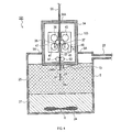
- the electrode material manufacturing system 1 includes a raw material preparation / processing unit 3, a storage container 5, and a mixing unit 6.
- the raw material creation / processing unit 3 includes a container 7, a piston 9, a die 11, a cutter 13, and an exhaust pipe 15.
- the raw material preparation / processing unit 3 corresponds to a raw material processing unit and a raw material preparation unit.
- the container 7 is a hollow cylindrical container having an open bottom.
- the axial direction of the cylinder is the vertical direction.
- the container 7 can store an ingot 17 of a raw material (for example, alkali metal) therein.
- the piston 9 includes a disk-shaped pressing portion 19 and a shaft portion 21.
- the pressing part 19 is accommodated in the ingot 17.
- the side surface of the pressing portion 19 is in contact with the inner surface of the container 7.
- the shaft portion 21 is inserted through an insertion hole 7 ⁇ / b> A provided in the upper portion of the container 7.
- the lower end of the shaft portion 21 is connected to the pressing portion 19, and the opposite end portion is connected to a drive mechanism (not shown) outside the container 7.
- the piston 9 moves up and down by the driving force transmitted from the driving mechanism.
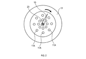
- the die 11 is a disk-shaped member having a plurality of die holes 11A.
- the die hole 11A is a circular hole.
- the die 11 is attached to the container 7 so as to close the opening below the container 7.
- the cutter 13 is a resin cutter attached to the bottom surface of the die 11.
- the cutter 13 and the lower surface of the die 11 are in contact with each other.
- the cutter 13 is rotatably attached to a shaft 23 located near the center of the die 11.
- the cutter 13 rotates about the shaft 23 by a driving force transmitted from a driving mechanism (not shown). When the cutter 13 rotates, the range in which the cutter 13 operates includes all the die holes 11A.
- the exhaust pipe 15 is connected to a vent hole 7B provided on the side surface of the container 7 at one end thereof.
- the exhaust pipe 15 is connected to a vacuum pump (not shown) at the opposite end.
- the storage container 5 includes an opening 5A on the upper side, and the raw material preparation / processing unit 3 is attached to the opening 5A.
- the die 11 and the cutter 13 are located inside the storage container 5.
- An electrolytic solution supply pipe 22 is connected to the upper portion of the side surface of the storage container 5.
- the electrolyte solution 25 can be supplied from the electrolyte solution supply pipe 22 into the storage container 5.
- the mixing unit 6 includes a rotary blade 24 near the bottom surface in the storage container 5.
- the mixing unit 6 can stir and mix the contents in the storage container 5 by rotating the rotary blade 24.
- the electrolytic solution 25 is put into the storage container 5 through the electrolytic solution supply pipe 22.
- the amount of the electrolytic solution 25 is set so that the bottom surface of the die 11 is immersed in the electrolytic solution 25.
- an active material 27 such as carbon is placed in the storage container 5.
- a raw material ingot 17 is placed inside the container 7. The ingot 17 is sandwiched from above and below by the die 11 and the piston 9.
- the inside of the container 7 is evacuated through the exhaust pipe 15.
- the raw material 29 in the form of a wire is extruded from the die hole 11A. Since the electrolytic solution 25 exists below the die 11, the raw material 29 having a wire form is extruded into the electrolytic solution 25.
- a divided raw material 31 is generated.
- the divided raw material 31 has the form of a short wire and is supplied into the storage container 5.
- This electrode material manufacturing system basically has the same configuration as that of the electrode material manufacturing system 1, but the die 11 is not a circular die hole but an elongated slit 33 as shown in FIG. A plurality.
- the piston 9 When the piston 9 is pushed down, a raw material having a sheet form is extruded from each slit 33.
- a divided raw material By dividing the raw material having a sheet form by rotating the cutter 13 at a constant period, a divided raw material is generated.
- the divided raw materials have a rectangular sheet form and are supplied into the storage container 5.
- the electrode material manufacturing system 101 includes a raw material creation / processing unit 103, a storage container 5, and a mixing unit 6.
- the raw material creation / processing unit 103 includes a housing 34, work rolls 35 and 37, support rolls 39, 41, 43 and 45, movable stands 47 and 49, and guide rolls 51 and 53.
- the raw material creation / processing unit 103 corresponds to a raw material processing unit and a raw material creation unit.
- the housing 34 is a hollow box-shaped container.
- the top plate is provided with an introduction slit 34A, and the bottom plate is provided with a lead-out slit 34B.
- the housing 34 accommodates work rolls 35 and 37, support rolls 39, 41, 43, and 45, movable bases 47 and 49, and guide rolls 51 and 53.
- the work rolls 35 and 37 are opposed to each other with a certain interval.
- the axis of the work roll 35 and the axis of the work roll 37 are parallel and at the same height.
- the gap between the work roll 35 and the work roll 37 is directly below the introduction slit 34A and above the lead-out slit 34B.
- the work roll 35 is supported by support rolls 39 and 41.
- the work roll 37 is supported by support rolls 43 and 45.
- the movable stand 47 supports the support rolls 39 and 41 in a rotatable manner.
- the movable base 47 can adjust the position in the left-right direction in FIG.
- the movable base 49 supports the support rolls 43 and 45 in a rotatable manner.
- the movable table 49 is urged in the direction A shown in FIG. 4 by an urging mechanism (not shown).
- the guide rolls 51 and 53 are located in the vicinity of the outlet slit 34B.
- the guide rolls 51 and 53 are opposed to each other with a certain interval.
- the axis of the guide roll 51 and the axis of the guide roll 53 are parallel and at the same height.
- the storage container 5 is provided with an opening 5A on the upper side, and a raw material preparation / processing unit 103 is attached to the opening 5A.
- a part of the lower side of the housing 34 is located inside the storage container 5.
- An electrolytic solution supply pipe 22 is connected to the upper portion of the side surface of the storage container 5.
- the electrolyte solution 25 can be supplied from the electrolyte solution supply pipe 22 into the storage container 5.
- the mixing unit 6 includes a rotary blade 24 near the bottom surface in the storage container 5.
- the mixing unit 6 can stir and mix the contents in the storage container 5 by rotating the rotary blade 24.
- the electrolytic solution 25 is put into the storage container 5 through the electrolytic solution supply pipe 22.
- the amount of the electrolytic solution 25 is set so that the bottom surface of the housing 34 is immersed in the electrolytic solution 25.
- an active material 27 such as carbon is placed in the storage container 5.
- the plate-shaped raw material 55 is introduced into the housing 34 from the introduction slit 34A.
- the plate-shaped raw material 55 is sent downward and pushed between the work rolls 35 and 37.
- the work rolls 35 and 37 rotate in the direction B in FIG. 4 while pressing the plate-shaped raw material 55.
- the plate-shaped raw material 55 is subjected to a rolling process by the work rolls 35 and 37 to become a raw material 57 having a sheet form.
- the thickness of the raw material 57 having a sheet form is smaller than the thickness of the plate-shaped raw material 55.
- the raw material 57 in the form of a sheet is guided by the guide rolls 51 and 53, passes through the lead-out slit 34 ⁇ / b> B, and is led out below the casing 34. Since the electrolytic solution 25 exists below the casing 34, the raw material 57 having a sheet form is led into the electrolytic solution 25. By dividing the raw material 57 having a sheet form by rotating the cutter 13 at a constant cycle, a divided raw material 59 is generated. The divided raw material 59 has a rectangular sheet form and is supplied into the storage container 5.
- the raw material preparation unit may be integrated with the raw material processing unit as in the above example, or may be a separate body.
- the electrode material manufacturing system according to the present disclosure is a mixture for mixing an aggregate containing a divided raw material and at least one of an active material and a solvent, which is stored in the storage container of (B). A unit may be further provided.
- an assembly including divided raw materials and active materials can be mixed by the mixing unit.
- the divided raw material can be uniformly dispersed in the active material, it becomes possible to uniformly dope the entire active material with the alkali metal in the subsequent steps.
- an assembly including, for example, an active material, divided raw materials, and a solvent can be mixed by the mixing unit.
- the active material and the alkali metal can be brought into contact with each other, so that the alkali metal can be doped into the active material.
- an assembly including divided raw materials, active materials, binders, organic solvents, and the like can be mixed by the mixing unit. In this case, it becomes possible to manufacture the slurry for electrode formation.
- the mixing unit is not particularly limited as long as it can mix the aggregate uniformly, and may be, for example, a unit that rotates, vibrates, or swings the storage container itself of (B), A stirrer, an ultrasonic vibrator, or the like that stirs and mixes the contents of the storage container (B) may be used, or a combination of both.
- the storage container (B) and the mixing unit may be integrated.
- Examples of the apparatus in which the storage container and the mixing unit of (B) are integrated include a known rotating mixer, a rotating / revolving mixer, a pressure kneader, and the like.
- the mixing unit may be a separate body from the storage container (B). Examples of the mixing unit that is separate from the storage container (B) include a known uniaxial stirrer and a magnetic stirrer.
- the electrode material manufacturing system of the present disclosure may further include a mixing container for mixing the divided raw material, active material, and solvent.
- the mixing container includes a mixing unit similar to the mixing unit (D).
- the divided raw materials can be dispersed in a solvent, and then the obtained dispersion and the active material or the slurry containing the active material can be mixed in the mixing container.
- the alkali metal contained in the raw material can be more uniformly dispersed.
- the electrode material manufacturing system of the present disclosure further includes a pressurization unit that statically pressurizes an assembly including divided raw materials and an active material, preferably in the presence of a solvent. Also good.
- the pressurization means applying a pressure larger than normal pressure.
- the “statically pressurizing” means pressurizing an assembly that has been left still (that is, substantially not subjected to the mixing treatment).
- the contact resistance between the active material particles can be reduced, so that the entire active material contained in the aggregate can be quickly and uniformly doped with alkali metal.
- the active material particles and the alkali metal hardly collide violently, so that the safety is further enhanced.
- the pressurization by the pressurization unit may be performed in the storage container (B) or may be performed outside the storage container (B).
- pressurization by the pressurizing unit is performed in the storage container of (B)
- an assembly stored in the storage container of (B) is an inner surface of the storage container of (B).
- a pressing unit that presses in the direction.
- the form of the pressing unit is not particularly limited as long as it can press the aggregate, and can be, for example, a plate shape, a rod shape, a spherical shape, or the like. It is preferable that the pressing unit has a plurality of through holes in a portion in contact with the assembly. In the case of having a plurality of through holes, for example, a solvent or alkali metal ions can be transmitted. Examples of the material constituting the pressing unit include metal, glass, resin, and nonwoven fabric. *
- pressurizing unit there is a pressurizing unit that pressurizes the aggregate by forming a flow of a solvent passing through the aggregate.
- a circulation pump can be incorporated.
- the manufacturing system uses a container (hereinafter referred to as a pressurization container) different from the storage container of (B) and pressurization. And a pressurizing unit that pressurizes the container.
- the mixing container (E) may be a pressurized container.
- the storage container of (B) is an aggregate containing divided raw materials and active materials, for example, and the active material is doped with an alkali metal
- a previous state ie, a precursor of the electrode material
- a dispersion liquid in which the divided raw materials are dispersed in a solvent can be produced in the storage container of (B).
- the electrode material manufacturing system of the present disclosure may further include a solvent supply unit that supplies a solvent into the storage container of (B).
- An alkali metal salt or an additive may be dissolved in the solvent.
- the solvent supply unit include a device that includes a container that stores a solvent and the like and a liquid feed pump, and further includes a stirring unit that stirs the solvent and the like as necessary.
- the electrode material manufacturing system of the present disclosure may include a slurry solvent supply unit that mixes an active material and a solvent to prepare a slurry, and supplies the prepared slurry into the storage container of (B). Good.
- the slurry may contain an alkali metal salt, an additive, a binder, a thickener, a conductive aid and the like.
- the slurry solvent supply unit include a container that contains a solvent and the like, a stirring unit that stirs the solvent, and a liquid feed pump.
- the electrode material manufacturing system according to the present disclosure may include an inert gas supply unit that supplies an inert gas such as argon into the storage container of (B).
- the electrode material manufacturing system of the present disclosure may include a filtration unit and a drying unit for removing the solvent after the alkali metal is doped into the active material in the solvent.
- a method for producing an electrode material according to the present disclosure includes a step of dividing at least a part of a raw material containing an alkali metal (hereinafter referred to as a division step) using the electrode material production system according to the present disclosure. .
- the electrode material examples include an electrode-forming slurry containing an alkali metal, an active material and a solvent, and an active material doped with an alkali metal.
- the electrode material is preferably a negative electrode material because the electrode material production system of the present disclosure is suitable for the treatment of the negative electrode active material.
- the dividing step since it becomes easy to divide the raw material, it is preferable to divide at least a part of the raw material containing the alkali metal in the solvent accommodated in the storage container (B). ) Is preferably divided by cutting at least part of the raw material containing the alkali metal in the solvent accommodated in the storage container.
- the solvent used in the dividing step is preferably the same as the solvent used in the dope step described later.
- the raw material and the active material which are divided in the storage container (B) or in the mixing container (E) different from the storage container (B) are included.
- a step of forming an aggregate can be performed.
- a step of doping an active material with an alkali metal (hereinafter referred to as a doping step) can be performed.
- Electrode material production system can be used, and the following solvents are particularly preferable. That is, ethylene carbonate, propylene carbonate, butylene carbonate, dimethyl carbonate, diethyl carbonate, methyl ethyl carbonate, ⁇ -butyrolactone, acetonitrile, dimethoxyethane, tetrahydrofuran, dioxolane, methylene chloride, sulfolane and the like are preferable.
- the solvent may be a single component or a mixed solvent of two or more components. It is preferable that an alkali metal salt such as a lithium salt or a sodium salt is dissolved in the solvent.
- an alkali metal salt such as a lithium salt or a sodium salt is dissolved in the solvent.
- the anion moiety constituting the alkali metal salt include phosphorus anions having a fluoro group such as PF 6 ⁇ , PF 3 (C 2 F 5 ) 3 ⁇ , PF 3 (CF 3 ) 3 ⁇ , and the like; BF 4 ⁇ , Boron anions having a fluoro group or a cyano group such as BF 2 (CF) 2 ⁇ , BF 3 (CF 3 ) ⁇ , B (CN) 4 —, etc .; N (FSO 2 ) 2 ⁇ , N (CF 3 SO 2 ) 2 -, N (C 2 F 5 SO 2) 2 - sulfonyl imide anion having a
- the concentration of the alkali metal ion (alkali metal salt) in the solution in which the alkali metal salt is dissolved (hereinafter referred to as the electrolyte for doping) is preferably 0.1 mol / L or more, more preferably 0.5 to Within the range of 1.5 mol / L. When it is within this range, doping of the alkali metal to the active material proceeds efficiently.
- additives such as vinylene carbonate, vinyl ethylene carbonate, 1-fluoroethylene carbonate, 1- (trifluoromethyl) ethylene carbonate, succinic anhydride, maleic anhydride, propane sultone, diethyl sulfone and the like are dissolved in the solvent. It may be.
- Examples of the method of bringing the divided raw material and active material into contact in the dope process include a method of kneading and mixing the two, and a method of applying ultrasonic vibration to both in the electrolyte for doping. Aspects are disclosed in JP 2012-204310 A, JP 2012-209195 A, JP 2014-51414 A, and the like.
- the divided material and the active material can be brought into contact by pressurizing the aggregate.
- the pressurizing pressure is preferably in the range of 0.001 to 20 MPa. When the pressure is within this range, the balance between the contact resistance between the active material particles and the diffusion of alkali metal ions is good, and the doping of the alkali metal to the active material proceeds efficiently.
- the pressurization time can be appropriately set according to the type and amount of the active material, the shape of the storage container and the pressing means, the amount of alkali metal dope, and the like.
- the aggregate when the aggregate is pressurized to bring the active material into contact with the divided raw material, the aggregate may further contain a conductive additive.
- the conductive assistant include carbon black, vapor grown carbon fiber, metal powder other than alkali metal, and the like.
- the dope rate can be increased by incorporating a conductive additive in the aggregate.
- the raw material and the active material divided in the storage container (B) are preferably mixed with a solvent in advance, or (B) After the raw material divided in the storage container is dispersed in a solvent, the obtained dispersion and the active material are preferably mixed in the mixing container (E).
- the divided raw material can be uniformly dispersed in the active material, it becomes easy to uniformly dope the alkali metal throughout the active material in the subsequent doping step.
- the order of supplying the divided raw material, active material, and solvent into the storage container (B) can be appropriately selected.
- the divided raw materials can be supplied into the storage container (B).
- the divided raw materials may be supplied into the storage container (B).
- the slurry containing the active material and the solvent may be supplied into the storage container (B) by the slurry solvent supply unit.
- a step of supplying the raw material divided into the storage container of (B), and a step of supplying a slurry containing an active material and a solvent into the storage container of (B) by the slurry solvent supply unit may be repeated alternately.
- the storage container (B) is preferably filled with an inert gas such as argon, and the dew point in the storage container (B) is preferably controlled to ⁇ 50 ° C. or lower.
- the active material and the divided raw material are contained in the storage container (B) or in the mixing container (E) different from the storage container (B).
- An organic solvent, a binder or the like may be mixed.
- Examples of the organic solvent include N-methylpyrrolidone and the like in addition to the organic solvents described above.
- the binder include rubber-based binders such as styrene-butadiene rubber (SBR) and NBR; fluorine-based resins such as polytetrafluoroethylene and polyvinylidene fluoride; polypropylene, polyethylene, disclosed in JP2009-246137A Fluorine-modified (meth) acrylic binder, polyimide and the like.
- SBR styrene-butadiene rubber
- fluorine-based resins such as polytetrafluoroethylene and polyvinylidene fluoride
- polypropylene polyethylene, disclosed in JP2009-246137A Fluorine-modified (meth) acrylic binder, polyimide and the like.
- Electrode-forming slurry examples include, for example, carbon black, graphite, vapor-grown carbon fiber, metal powder and the like; carboxyl methyl cellulose, its Na salt or ammonium salt, methyl cellulose, hydroxymethyl cellulose, ethyl cellulose , Hydroxypropylcellulose, polyvinyl alcohol, oxidized starch, phosphorylated starch, casein, and the like.
- the electrode manufacturing method of the present disclosure manufactures an electrode using the electrode material manufactured by the electrode material manufacturing method.
- the electrode to be manufactured may be a positive electrode or a negative electrode, but a negative electrode is preferable because the method for manufacturing an electrode material of the present disclosure is suitable for manufacturing a negative electrode material.
- an electrode for example, there is an electrode provided with a current collector and an active material layer provided on the surface thereof.
- an electrode-forming slurry is produced by the method described in the above-mentioned section “2. Method for producing electrode material”, and the electrode-forming slurry is used to activate on the current collector. The method of forming a material layer is mentioned. The electrode forming slurry corresponds to the electrode material.
- an active material doped with an alkali metal is manufactured by the method described in the section of “2. Method for manufacturing electrode material”, and then an active material doped with an alkali metal is contained.
- a method of producing a slurry and further forming an active material layer on the current collector using the slurry is exemplified.
- the active material doped with alkali metal corresponds to the electrode material.
- the current collector in the case of producing a negative electrode, for example, a metal foil such as copper, nickel, and stainless steel is preferable. Further, the current collector may be one in which a conductive layer mainly composed of a carbon material is formed on the metal foil.
- the thickness of the current collector can be, for example, 5 to 50 ⁇ m.
- the active material layer on the current collector is formed, for example, by applying a slurry on the current collector and drying it.
- the thickness of the active material layer is not particularly limited, but is, for example, 5 to 500 ⁇ m, preferably 10 to 200 ⁇ m, particularly preferably 10 to 100 ⁇ m.
- the slurry containing an active material doped with an alkali metal may contain a binder, an organic solvent, and other components in addition to the active material.
- a binder As the binder, the organic solvent, and other components, those similar to the binder, organic solvent, and other components listed in the above-mentioned section “2. Method for producing electrode material” can be used. Further, as disclosed in JP-A-2004-281162, etc., an electrode containing a gel electrolyte can be produced by using a gelling agent as a binder and adding an electrolyte to the slurry.
- the electrode manufactured by the electrode manufacturing method of the present disclosure has a small irreversible capacity.
- decomposition of the electrolytic solution on the electrode is suppressed.
- Capacitor Manufacturing Method is a method of manufacturing a capacitor including a positive electrode, a negative electrode, and an electrolyte, and includes a step of manufacturing the negative electrode by the electrode manufacturing method of the present disclosure.
- the capacitor is not particularly limited as long as it is a capacitor using insertion / extraction of alkali metal ions, and examples thereof include a lithium ion capacitor and a sodium ion capacitor. Among these, a lithium ion capacitor is preferable.
- the method for manufacturing a capacitor according to the present disclosure includes, for example, a step of manufacturing a negative electrode by the electrode manufacturing method, a step of manufacturing a positive electrode, a step of storing the obtained negative electrode and positive electrode in an exterior body, and an electrolyte in the exterior body Injecting.
- the process for producing the positive electrode is not particularly limited, and a known method can be adopted. It is preferable to use activated carbon as the positive electrode active material contained in the positive electrode.
- activated carbon As a process of housing the negative electrode and the positive electrode in the exterior body, for example, a laminated body in which three or more plate-like structural units composed of the positive electrode and the negative electrode and a separator interposed therebetween are laminated is manufactured. The method of enclosing in an exterior film is mentioned.
- the method of accommodating in a cylindrical container is mentioned.
- a separator the nonwoven fabric or porous film which uses a cellulose rayon, polyethylene, a polypropylene, polyamide, polyester, a polyimide etc. as a raw material can be mentioned, for example.
- the step of injecting the electrolyte into the exterior body is not particularly limited, and a known method can be employed.
- the electrolyte is usually in a liquid form, and the same electrolyte as the dope electrolyte described in the above section “2. Method for producing electrode material” can be used.
- the electrolyte may have a gel or solid form for the purpose of preventing leakage.
- a battery manufacturing method of the present disclosure is a method of manufacturing a battery including a positive electrode, a negative electrode, and an electrolyte, and includes a step of manufacturing the negative electrode by the electrode manufacturing method of the present disclosure.
- the battery is not particularly limited as long as it uses insertion / extraction of alkali metal ions, and may be a primary battery or a secondary battery. Examples of the battery include a lithium ion secondary battery and a sodium ion secondary battery. Among these, a lithium ion secondary battery is preferable.
- the battery manufacturing method of the present disclosure is basically the same as the method described in “4. Capacitor manufacturing method” except for the type of positive electrode active material to be used.
- the positive electrode active material an organic active material such as a nitroxy radical compound and oxygen can be used in addition to those exemplified in the section of “1. Electrode material production system”.
- the battery manufactured by the battery manufacturing method of the present disclosure includes a negative electrode with a small irreversible capacity, and thus has high energy density and excellent cycle characteristics.
Landscapes
- Engineering & Computer Science (AREA)
- Chemical & Material Sciences (AREA)
- Power Engineering (AREA)
- Chemical Kinetics & Catalysis (AREA)
- Electrochemistry (AREA)
- General Chemical & Material Sciences (AREA)
- Microelectronics & Electronic Packaging (AREA)
- Inorganic Chemistry (AREA)
- Manufacturing & Machinery (AREA)
- Materials Engineering (AREA)
- Battery Electrode And Active Subsutance (AREA)
- Electric Double-Layer Capacitors Or The Like (AREA)
- Fixed Capacitors And Capacitor Manufacturing Machines (AREA)
Abstract
電極材料の製造システムは、活物質及び溶媒の少なくとも一方を収納する収納容器と、アルカリ金属を含む原料の少なくとも一部を分割し、前記収納容器内に供給する原料処理ユニットとを備える。
Description
本国際出願は、2015年12月22日に日本国特許庁に出願された日本国特許出願第2015-250193号に基づく優先権を主張するものであり、日本国特許出願第2015-250193号の全内容を本国際出願に参照により援用する。
本開示は、電極材料の製造システム、並びに、電極材料、電極、電池及びキャパシタの製造方法に関する。
近年、電子機器の小型化及び軽量化は目覚ましく、それに伴い、当該電子機器の駆動用電源として用いられる電池に対しても小型化及び軽量化の要求が一層高まっている。
このような小型化及び軽量化の要求を満足するために、リチウムイオン二次電池に代表される非水電解質二次電池が開発されている。また、高エネルギー密度特性及び高出力特性を必要とする用途に対応する蓄電デバイスとして、リチウムイオンキャパシタが知られている。さらに、リチウムより低コストで資源的に豊富なナトリウムを用いたナトリウムイオン型の電池やキャパシタも知られている。
このような小型化及び軽量化の要求を満足するために、リチウムイオン二次電池に代表される非水電解質二次電池が開発されている。また、高エネルギー密度特性及び高出力特性を必要とする用途に対応する蓄電デバイスとして、リチウムイオンキャパシタが知られている。さらに、リチウムより低コストで資源的に豊富なナトリウムを用いたナトリウムイオン型の電池やキャパシタも知られている。
このような電池やキャパシタにおいては、様々な目的のために、予めアルカリ金属を電極活物質にドープするプロセス(一般にプレドープと呼ばれている)が採用されている。例えば、リチウムイオンキャパシタでは、負極電位を下げエネルギー密度を高めることを目的としてリチウムのプレドープが行われる。この場合は、貫通孔を有する集電体を利用してセル内で負極活物質にプレドープを行う方法が主流となっている(例えば、特許文献1参照)。
また、リチウムイオン二次電池では、負極の不可逆容量を低減させることを目的としてプレドープが行われる。この場合は、前記方法の他、電池を組み立てる前に負極活物質にプレドープを行う方法が採用されている(例えば、特許文献2、3参照)。さらに、ナトリウムイオン型の蓄電デバイスを作製するにあたっても、蓄電デバイスを組み立てる前に負極にナトリウムをプレドープする方法が採用されている(特許文献4)。
また、特許文献5では、二次電池の初期充電時における負極上での電解液の分解を抑制するために、負極として使用する繊維状炭素材料を非水溶媒中でn-ブチルリチウムに接触させ、その繊維状炭素材料にリチウムイオンを吸蔵させることが提案されている。
しかしながら、上に挙げた従来の方法は、製造コストや簡便さの点から実用に供するには難があった。
これに対し、特許文献6、7では、リチウムを短時間で、且つ容易にプレドープする方法として、リチウムドープ可能材料と、細かく切断したリチウム金属又は粒状のリチウム金属とを溶剤の存在下において混練混合してプレドープする方法が提案されている。
これに対し、特許文献6、7では、リチウムを短時間で、且つ容易にプレドープする方法として、リチウムドープ可能材料と、細かく切断したリチウム金属又は粒状のリチウム金属とを溶剤の存在下において混練混合してプレドープする方法が提案されている。
また、特許文献8では、炭素材料と、ポリマーで被覆したリチウムの微粒子等とを混練して得られたペーストを集電体上に塗工し、そしてそのペーストを乾燥させて負極を作製し、炭素材料にリチウムイオンを吸蔵させて、電気化学キャパシタを製造することが開示されている。
しかしながら、細かく切断したリチウム金属や粒状のリチウム金属は、互いにくっ付き易く、非常に取り扱い難いという問題がある。また、細かく切断したり粒状にしたりすると、リチウム金属の比表面積が大きくなるため、危険性が増すという問題もある。
かかる問題は、リチウム金属の表面をポリマー等で被覆することによりある程度は改善されるものの、リチウム金属をポリマー等で被覆する際に同様の問題があるため、本質的な問題の解決には至ってない状況にある。また、リチウム金属をポリマー等で処理することで、製造コストが非常に高くなるという問題もある。
本開示の一局面は、アルカリ金属がプレドープされた電極材料を低コストで且つ安全に製造することができる電極材料の製造システム、並びに、電極材料、電極、電池及びキャパシタの製造方法を提供することが好ましい。
本開示の一態様は、活物質及び溶媒の少なくとも一方を収納する収納容器と、アルカリ金属を含む原料の少なくとも一部を分割し、前記収納容器内に供給する原料処理ユニットと、を備える電極材料の製造システムである。この製造システムを用いれば、アルカリ金属がプレドープされた電極材料を低コストで且つ安全に製造することができる。
1、101…電極材料の製造システム、3、103…原料作成/処理ユニット、5…収納容器、5A…開口部、6…混合ユニット、7…コンテナ、7A…挿通孔、7B…通気孔、9…ピストン、11…ダイ、11A…ダイ孔、13…カッター、15…排気管、17…インゴット、19…押圧部、21…軸部、23…軸、24…回転翼、25…電解液、27…活物質、29…ワイヤの形態を有する原料、31…分割された原料、33…スリット、34…筐体、34A…導入スリット、34B…導出スリット、35、37…作業ロール、39、41、43、45…支持ロール、47、49…可動台、51、53…ガイドロール、55…板状の原料、57…シートの形態を有する原料、59…分割された原料
1.電極材料の製造システム
(A)原料処理ユニット
原料処理ユニットは、アルカリ金属を含む原料の少なくとも一部を分割し、分割された原料を収納容器内に供給する。アルカリ金属としては、例えば、リチウム、ナトリウムが挙げられる。
(A)原料処理ユニット
原料処理ユニットは、アルカリ金属を含む原料の少なくとも一部を分割し、分割された原料を収納容器内に供給する。アルカリ金属としては、例えば、リチウム、ナトリウムが挙げられる。
分割される前の原料の形態は特に限定されるものではなく、例えば、シート、ワイヤ、ロッド、溶融体等の形態が挙げられる。分割の処理が容易になるため、シート又はワイヤの形態が好ましい。
本開示の電極材料の製造システムは、原料を原料処理ユニットに供給する供給ユニットを備えていてもよい。供給ユニットにより供給される原料の形態は特に限定されるものではなく、例えば、シート、ワイヤ、ロッド、溶融体等の形態が挙げられるが、シート又はワイヤであることが好ましい。供給ユニットは、シート又はワイヤが予め巻き取られたリールからこれらを引き出して、原料処理ユニットに供給することができる。
シートにおける幅は2mm~10cmの範囲が好ましい。シートにおける厚さは10μm~1cmの範囲が好ましい。ワイヤの直径は1mm~2cmの範囲が好ましい。シートの幅及び厚さ並びにワイヤの直径は、ドープする活物質の量に応じて適宜に設定することができるが、上記の範囲内である場合、ドープ効率の点で優れる。
分割され、収納容器に供給されるワイヤの長さは2mm~10cmの範囲が好ましい。分割され、収納容器に供給されるシートの長さは2mm~10cmの範囲が好ましい。分割されたシート及びワイヤの長さは、ドープする活物質の量に応じて適宜に設定することができるが、上記の範囲内である場合、分割効率及びドープ効率の点で優れる。
原料は、実質的にアルカリ金属のみから成っていてもよいし、アルカリ金属に加えて他の成分を含んでいてもよい。原料として、例えば、アルカリ金属の合金、アルカリ金属のシートと他の金属(例えば、銅)のシートとの積層体、アルカリ金属のシートと樹脂(例えば、ポリエチレン、ポリプロピレン、PET、ポリ塩化ビニル、ポリ塩化ビニリデン)製シートとの積層体等が挙げられる。
原料処理ユニットが分割を行うことで生じた分割片は、分割前の原料より小さい。分割の方法は特に限定されないが、生産性及び製造コストの点から、原料処理ユニットは、例えば、切断ユニットにより原料を切断することで分割することが好ましい。
切断ユニットは特に限定されるものではなく、例えば、切断刃を用いるもの、レーザー又はプラズマ等の溶断のための熱源を利用するものが挙げられるが、製造コストの点から切断刃を用いるものが好ましい。切断刃を構成する材料は特に限定されるものではなく、例えば、金属、セラミックス、樹脂等が挙げられるが、アルカリ金属の付着し難さの点から樹脂であることが好ましい。
樹脂の種類としては、ポリエチレン、ポリプロピレン、ポリアセタールが好ましい。切断刃を用いる切断ユニットの具体的な態様は、例えば、特開昭59-173955号公報、特開平7-136978号公報に開示されている。
切断後における原料の長さは、2mm~10cmの範囲が好ましい。この範囲内である場合、切断効率及びドープ効率の点で優れる。
原料処理ユニットは、溶融したアルカリ金属を分散媒中に分散させ、粒状の分散体を生成することでアルカリ金属を分割するものであってもよい。溶融したアルカリ金属は分割前の原料に対応する。粒状の分散体、及びそれが固化したアルカリ金属粒子は、分割後の原料に対応する。粒状の分散体の直径は10μm~1cmの範囲が好ましい。この範囲内である場合、ドープ効率の点で優れる。
原料処理ユニットは、溶融したアルカリ金属を分散媒中に分散させ、粒状の分散体を生成することでアルカリ金属を分割するものであってもよい。溶融したアルカリ金属は分割前の原料に対応する。粒状の分散体、及びそれが固化したアルカリ金属粒子は、分割後の原料に対応する。粒状の分散体の直径は10μm~1cmの範囲が好ましい。この範囲内である場合、ドープ効率の点で優れる。
この場合の原料処理ユニットは、例えば、少なくとも溶融したアルカリ金属及び分散媒を収納する容器と、容器内を攪拌する撹拌ユニットと、容器を加熱する加熱ユニットとを備えていることが好ましい。溶融させたアルカリ金属は、分散媒に加える前に加熱して溶融させたアルカリ金属であってもよいし、アルカリ金属の融点以上の温度に加熱した分散媒中で溶融させたアルカリ金属であってもよい。
分散媒としては、引火点が90℃以上の炭化水素油が好ましい。アルカリ金属を粒状の分散体とした後、例えば、分散体の冷却、濾過による分散媒の除去、炭化水素系溶媒によるアルカリ金属粒子の洗浄及びアルカリ金属粒子の乾燥を行うことができる。この場合、原料処理ユニットは、冷却ユニット、濾過ユニット、炭化水素系溶媒を供給するユニット、乾燥ユニット等をさらに備えていてもよい。溶融したアルカリ金属を分散させ、アルカリ金属粒子を得るための装置の具体的な態様は、例えば、特表2010-535936の実施例に開示されている。
(B)収納容器
収納容器は、活物質及び溶媒の少なくとも一方を収納する。また、収納容器内には、原料処理ユニットにより分割された原料が供給される。よって、収納容器は、少なくとも、分割された原料と、活物質及び溶媒の少なくとも一方と、を含む集合体を収納することができる。この集合体は、例えば、電極材料、その前駆体、及び、分割された原料を溶媒中に分散させた分散液の製造に使用できる。
収納容器は、活物質及び溶媒の少なくとも一方を収納する。また、収納容器内には、原料処理ユニットにより分割された原料が供給される。よって、収納容器は、少なくとも、分割された原料と、活物質及び溶媒の少なくとも一方と、を含む集合体を収納することができる。この集合体は、例えば、電極材料、その前駆体、及び、分割された原料を溶媒中に分散させた分散液の製造に使用できる。
電極材料としては、例えば、アルカリ金属、活物質及び溶媒を含有する電極形成用スラリー、アルカリ金属をドープした活物質が挙げられる。また、電極材料の前駆体としては、例えば、分割された原料、及び活物質を含む混合物であって、活物質にアルカリ金属をドープする前の状態のものが挙げられる。また、分割された原料を溶媒中に分散させた分散液は、活物質の非存在下、分割された原料を溶媒中に分散させたものである。
収納容器の大きさや形状は、この収納容器内で行われる処理の方法、処理する物質の量等に応じて適宜に設定できる。また、収納容器を構成する材料も、この収納容器内で行われる処理の方法等に応じて、金属、ガラス、セラミックス、樹脂等から適宜に選択できる。
収納容器は、活物質を収納することができる。収容される活物質は、アルカリ金属イオンの挿入/脱離を利用する電池やキャパシタに適用可能な電極活物質であれば特に限定されるものではなく、負極活物質であってもよいし、正極活物質であってもよい。
負極活物質の種類は特に限定されるものではないが、例えば、黒鉛、易黒鉛化炭素、難黒鉛化炭素、黒鉛粒子をピッチや樹脂の炭化物で被覆した複合炭素材料等の炭素材料;リチウムと合金化が可能なSi、Sn等の金属若しくは半金属又はこれらの酸化物を含む材料等が挙げられる。炭素材料の具体例としては、特開2013-258392号公報に記載の炭素材料が挙げられる。リチウムと合金化が可能な金属若しくは半金属又はこれらの酸化物を含む材料の具体例としては、特開2005-123175号公報、特開2006-107795号公報に記載の材料が挙げられる。
正極活物質としては、例えば、マンガン酸化物、バナジウム酸化物等の遷移金属酸化物;硫黄単体、金属硫化物等の硫黄系活物質等が挙げられる。
正極活物質及び負極活物質のいずれにおいても、単一の物質から成るものであってもよいし、2種以上の物質を混合して成るものであってもよい。本開示の電極材料の製造システムは、負極活物質の処理に適しており、特に、負極活物質が炭素材料又はSi若しくはその酸化物を含む材料である場合に一層適している。
正極活物質及び負極活物質のいずれにおいても、単一の物質から成るものであってもよいし、2種以上の物質を混合して成るものであってもよい。本開示の電極材料の製造システムは、負極活物質の処理に適しており、特に、負極活物質が炭素材料又はSi若しくはその酸化物を含む材料である場合に一層適している。
一般的に、活物質として炭素材料を用いる場合、炭素材料の粒子径が小さくなると、内部抵抗の低い蓄電デバイスが得られる一方、不可逆容量が大きくなる、蓄電デバイスを充電状態で保持した際に発生するガスの量が多くなる等の問題が生じる。また、活物質としてSi又はその酸化物を含む材料を用いる場合も、一般的に不可逆容量が大きくなる傾向にある。本開示の電極材料の製造システムを使用すれば、微細化されたアルカリ金属を活物質粒子中に均一に分散させることができるため、活物質として粒子径の小さい炭素材料やSi又はその酸化物を含む材料を用いる場合であっても、かかる問題を抑制することができる。
収納容器は、溶媒を収納することができる。本開示の電極材料の製造システムを用いてアルカリ金属をドープした活物質を製造する場合、前記溶媒としては、アルカリ金属イオン伝導性を有する溶媒であれば特に限定されるものではないが、有機溶媒が好ましく、特に非プロトン性の有機溶媒が好ましい。前記溶媒にはアルカリ金属塩が溶解していることが好ましい。アルカリ金属塩としては、電解質として用いられる公知のリチウム塩又はナトリウム塩等が挙げられる。前記溶媒には、さらに、電解液に添加される公知の添加剤が溶解していてもよい。
また、本開示の電極材料の製造システムを用いてアルカリ金属及び活物質を含有する電極形成用スラリーを製造する場合、収納容器は、前記溶媒の他、バインダー、増粘剤等、電極形成用スラリーを構成する公知の成分をさらに収納するものであってもよい。また、収納容器は、上述した成分の他、導電助剤をさらに収納するものであってもよい。
収納容器は、例えば、その上側に開口部を備えるものであってもよい。そして、原料処理ユニットを、開口部の上側に配置することができる。その場合、原料処理ユニットにより分割された原料を収納容器内に供給することが一層容易になる。
また、原料処理ユニットは、収納容器の底面に配置してもよい。底面に原料処理ユニットを配置した場合、原料の比重が小さいと、原料を収納容器の底面から、上方向に供給しながら、原料を分割(例えば切断)することができる。そのため、原料の分割が一層容易になる。
(C)原料作成ユニット
本開示の電極材料の製造システムは、押出又は圧延により、シート又はワイヤの形態を有する原料を作成する原料作成ユニットをさらに備えていてもよい。
本開示の電極材料の製造システムは、押出又は圧延により、シート又はワイヤの形態を有する原料を作成する原料作成ユニットをさらに備えていてもよい。
押出によりワイヤの形態を有する原料を作成する原料作成ユニットを備えた電極材料の製造システムの例を図1、図2に基づき説明する。電極材料の製造システム1は、原料作成/処理ユニット3と、収納容器5と、混合ユニット6と、を備える。
原料作成/処理ユニット3は、コンテナ7、ピストン9、ダイ11、カッター13、及び排気管15を備える。なお、原料作成/処理ユニット3は、原料処理ユニットと、原料作成ユニットとに対応する。
コンテナ7は、下方が開口した中空円筒形状の容器である。円筒の軸方向は鉛直方向である。コンテナ7は、その内部に原料(例えばアルカリ金属)のインゴット17を収納可能である。ピストン9は、円盤状の押圧部19と軸部21とから成る。押圧部19はインゴット17内に収容されている。押圧部19の側面は、コンテナ7の内側面と接している。軸部21は、コンテナ7の上部に設けられた挿通孔7Aに挿通されている。軸部21の下端は押圧部19に接続され、反対側の端部はコンテナ7の外部において図示しない駆動機構に接続している。その駆動機構から伝達される駆動力により、ピストン9は上下動する。
ダイ11は、複数のダイ孔11Aを備えた円盤状部材である。ダイ孔11Aは円形の孔である。ダイ11は、コンテナ7の下方における開口部を塞ぐように、コンテナ7に取り付けられている。カッター13は、ダイ11の底面に取り付けられた樹脂製のカッターである。カッター13とダイ11の下面とは接している。カッター13は、ダイ11の中心付近に位置する軸23に回転可能に取り付けられている。カッター13は、図示しない駆動機構から伝達される駆動力により、軸23を中心として回転する。カッター13が回転するとき、カッター13が動作する範囲には、全てのダイ孔11Aが含まれる。
排気管15は、その一端においてコンテナ7の側面に設けられた通気孔7Bに接続している。排気管15は反対側の端部において図示しない真空ポンプに接続している。
収納容器5は、上方に開口部5Aを備え、その開口部5Aに、原料作成/処理ユニット3が取り付けられている。ダイ11、及びカッター13は収納容器5の内部に位置する。収納容器5の側面のうち上方寄りの部分に、電解液供給管22が接続されている。電解液供給管22から収納容器5の内部に電解液25を供給することができる。
収納容器5は、上方に開口部5Aを備え、その開口部5Aに、原料作成/処理ユニット3が取り付けられている。ダイ11、及びカッター13は収納容器5の内部に位置する。収納容器5の側面のうち上方寄りの部分に、電解液供給管22が接続されている。電解液供給管22から収納容器5の内部に電解液25を供給することができる。
混合ユニット6は、収納容器5内のうち、底面付近に回転翼24を備える。混合ユニット6は、回転翼24を回転させることにより、収納容器5内の収容物を攪拌、混合することができる。
電極材料の製造システム1を使用するとき、電解液供給管22を通して、収納容器5内に電解液25を入れておく。電解液25の量は、ダイ11の底面が電解液25に浸る量とする。また、収納容器5内に、カーボン等の活物質27を入れておく。また、コンテナ7の内部に原料のインゴット17を入れておく。インゴット17は、ダイ11とピストン9とにより上下から挟まれる。また、排気管15を通じてコンテナ7内を真空引きしておく。
次に、ピストン9を押し下げる。このとき、ダイ孔11Aから、ワイヤの形態を有する原料29が押出される。ダイ11より下方には電解液25が存在するので、ワイヤの形態を有する原料29は電解液25中に押し出される。一定の周期でカッター13を回転させ、ワイヤの形態を有する原料29を切断することで、分割された原料31が生じる。分割された原料31は短いワイヤの形態を有し、収納容器5内に供給される。
次に、押出によりシートの形態を有する原料を作成する原料作成ユニットを備えた電極材料の製造システムの例を図3に基づき説明する。この電極材料の製造システムは、基本的には、前記の電極材料の製造システム1と同様の構成を有するが、図3に示すように、ダイ11は、円形のダイ孔ではなく、細長いスリット33を複数有する。ピストン9を押し下げたとき、それぞれのスリット33から、シートの形態を有する原料が押出される。一定の周期でカッター13を回転させ、シートの形態を有する原料を切断することで、分割された原料が生じる。分割された原料は、矩形のシートの形態を有し、収納容器5内に供給される。
次に、圧延によりシートの形態を有する原料を作成する原料作成ユニットを備えた電極材料の製造システムの例を図4に基づき説明する。電極材料の製造システム101は、原料作成/処理ユニット103と、収納容器5と、混合ユニット6と、を備える。
原料作成/処理ユニット103は、筐体34、作業ロール35、37、支持ロール39、41、43、45、可動台47、49、及びガイドロール51、53を備える。なお、原料作成/処理ユニット103は、原料処理ユニットと、原料作成ユニットとに対応する。
筐体34は、中空箱状の容器である。その天板には、導入スリット34Aが設けられ、その底板には、導出スリット34Bが設けられている。筐体34は、作業ロール35、37、支持ロール39、41、43、45、可動台47、49、及びガイドロール51、53を収容している。
作業ロール35、37は、一定の間隔をおいて対向している。作業ロール35の軸と作業ロール37の軸とは、平行であり、同じ高さにある。作業ロール35と作業ロール37との隙間は、導入スリット34Aの真下にあり、導出スリット34Bの真上にある。作業ロール35は、支持ロール39、41により支持されている。作業ロール37は、支持ロール43、45により支持されている。
可動台47は、支持ロール39、41を回転自在に支持する。可動台47は、図4における左右方向での位置を調整可能である。可動台49は、支持ロール43、45を回転可能に支持する。可動台49は、図示しない付勢機構により、図4に示す方向Aに付勢されている。
ガイドロール51、53は、導出スリット34B付近に位置する。ガイドロール51、53は、一定の間隔をおいて対向している。ガイドロール51の軸とガイドロール53の軸とは、平行であり、同じ高さにある。
収納容器5は、上方に開口部5Aを備え、その開口部5Aに、原料作成/処理ユニット103が取り付けられている。筐体34のうち、下側の一部は収納容器5の内部に位置する。収納容器5の側面のうち上方寄りの部分に、電解液供給管22が接続されている。電解液供給管22から収納容器5の内部に電解液25を供給することができる。
混合ユニット6は、収納容器5内のうち、底面付近に回転翼24を備える。混合ユニット6は、回転翼24を回転させることにより、収納容器5内の収容物を攪拌、混合することができる。
電極材料の製造システム101を使用するとき、電解液供給管22を通して、収納容器5内に電解液25を入れておく。電解液25の量は、筐体34の底面が電解液25に浸る量とする。また、収納容器5内に、カーボン等の活物質27を入れておく。
次に、導入スリット34Aから、板状の原料55を筐体34の内部に導入する。板状の原料55は、下方に送られ、作業ロール35、37の間に押し込まれる。そのとき、作業ロール35、37は、板状の原料55を加圧しながら、図4における方向Bに回転する。板状の原料55は、作業ロール35、37による圧延処理を施され、シートの形態を有する原料57となる。シートの形態を有する原料57の厚みは、板状の原料55の厚みより小さい。
シートの形態を有する原料57は、ガイドロール51、53によりガイドされ、導出スリット34Bを通り、筐体34の下方に導出される。筐体34の下方には電解液25が存在するので、シートの形態を有する原料57は電解液25中に導出される。一定の周期でカッター13を回転させ、シートの形態を有する原料57を切断することで、分割された原料59が生じる。分割された原料59は矩形のシートの形態を有し、収納容器5内に供給される。
なお、原料作成ユニットは、前記の例のように、原料処理ユニットと一体であってもよいし、別体であってもよい。
(D)混合ユニット
本開示の電極材料の製造システムは、前記(B)の収納容器内に収容された、分割された原料と、活物質及び溶媒の少なくとも一方とを含む集合体を混合する混合ユニットをさらに備えていてもよい。
(D)混合ユニット
本開示の電極材料の製造システムは、前記(B)の収納容器内に収容された、分割された原料と、活物質及び溶媒の少なくとも一方とを含む集合体を混合する混合ユニットをさらに備えていてもよい。
混合ユニットにより、例えば、分割された原料と活物質とを含む集合体を混合することができる。この場合、分割された原料を活物質中に均一に分散させることができるため、その後の工程においてアルカリ金属を活物質全体に均一にドープすることが可能となる。
また、混合ユニットにより、例えば、活物質と、分割された原料と、溶媒とを含む集合体を混合することができる。この場合、活物質とアルカリ金属とを接触させ、活物質へのアルカリ金属のドープを進行させることができる。
また、混合ユニットにより、例えば、分割された原料、活物質、バインダー、有機溶媒等を含む集合体を混合することができる。この場合、電極形成用スラリーを製造することが可能となる。
混合ユニットは、集合体を均一に混合することができるものであれば特に限定されず、例えば、前記(B)の収納容器自体を回転、振動、揺動等させるものであってもよいし、前記(B)の収納容器を固定してその内容物を攪拌、混合する攪拌機、超音波振動子等であってもよいし、両者を組み合わせたものであってもよい。
前記(B)の収納容器と混合ユニットとは一体であってもよい。前記(B)の収納容器と混合ユニットとが一体となった装置の例として、公知の自転式ミキサー、自転公転式ミキサー、加圧ニーダー等が挙げられる。また、混合ユニットは前記(B)の収納容器と別体であってもよい。前記(B)の収納容器と別体である混合ユニットの例として、公知の一軸攪拌機、マグネチックスターラー等が挙げられる。
(E)混合容器
本開示の電極材料の製造システムは、分割された原料、活物質、及び溶媒を混合するための混合容器をさらに備えていてもよい。混合容器は前記(D)の混合ユニットと同様の混合ユニットを備えている。
本開示の電極材料の製造システムは、分割された原料、活物質、及び溶媒を混合するための混合容器をさらに備えていてもよい。混合容器は前記(D)の混合ユニットと同様の混合ユニットを備えている。
例えば、前記(B)の収納容器において、分割された原料を溶媒中に分散させ、次に、得られた分散液と、活物質又は活物質を含むスラリーとを混合容器において混合することができる。この場合、原料に含まれるアルカリ金属を一層均一に分散させることができる。
また、混合容器において、溶媒の存在下、活物質とアルカリ金属とを接触させ、活物質へのアルカリ金属のドープを進行させることもできる。
(F)加圧ユニット
本開示の電極材料の製造システムは、分割された原料と活物質とを含む集合体を、好ましくは溶媒の存在下、静的に加圧する加圧ユニットをさらに備えていてもよい。前記加圧とは、常圧より大きい圧力を加えることを意味する。また、前記「静的に加圧する」とは、静置された(すなわち混合処理を実質的に行っていない)集合体を加圧することを意味する。活物質を含む集合体を加圧する場合、活物質粒子間の接触抵抗を低下させることができるため、集合体に含まれる活物質全体にアルカリ金属を迅速かつ均一にドープすることが可能となる。また、静的に加圧された状態においては、活物質粒子とアルカリ金属とが激しく衝突しにくいため、安全性も一層高くなる。
(F)加圧ユニット
本開示の電極材料の製造システムは、分割された原料と活物質とを含む集合体を、好ましくは溶媒の存在下、静的に加圧する加圧ユニットをさらに備えていてもよい。前記加圧とは、常圧より大きい圧力を加えることを意味する。また、前記「静的に加圧する」とは、静置された(すなわち混合処理を実質的に行っていない)集合体を加圧することを意味する。活物質を含む集合体を加圧する場合、活物質粒子間の接触抵抗を低下させることができるため、集合体に含まれる活物質全体にアルカリ金属を迅速かつ均一にドープすることが可能となる。また、静的に加圧された状態においては、活物質粒子とアルカリ金属とが激しく衝突しにくいため、安全性も一層高くなる。
加圧ユニットによる加圧は、前記(B)の収納容器内で行われるものであってもよいし、前記(B)の収納容器外で行われるものであってもよい。加圧ユニットによる加圧を前記(B)の収納容器内で行う場合、加圧ユニットとしては、例えば、前記(B)の収納容器に収容された集合体を前記(B)の収納容器の内面の方向に押圧する押圧ユニットが挙げられる。
前記押圧ユニットの形態は、集合体を押圧できるものであれば特に限定されず、例えば、板状、棒状、球状等とすることができる。押圧ユニットは、集合体に接する部分に複数の貫通孔を有することが好ましい。複数の貫通孔を有する場合、例えば、溶媒やアルカリ金属イオンを透過させることができる。押圧ユニットを構成する材料としては、例えば、金属、ガラス、樹脂、不織布等が挙げられる。
また、他の加圧ユニットとして、集合体を通過する溶媒の流れを形成することで集合体を加圧する加圧ユニットが挙げられる。溶媒により集合体を加圧する具体的な手段としては、例えば、循環ポンプを組み込むことが挙げられる。
加圧ユニットによる加圧を前記(B)の収納容器外で行う場合、例えば、製造システムは、前記(B)の収納容器とは別の容器(以下では加圧容器とする)と、加圧容器内において加圧を行う加圧ユニットとを備えることができる。前記(E)の混合容器を加圧容器としてもよい。
なお、加圧ユニットによる加圧を加圧容器で行う場合、前記(B)の収納容器では、例えば、分割された原料、活物質を含む集合体であって、活物質はアルカリ金属をドープする前の状態であるもの(すなわち電極材料の前駆体)を製造することができる。また、加圧ユニットによる加圧を加圧容器で行う場合、前記(B)の収納容器では、分割された原料を溶媒中に分散させた分散液を製造することもできる。
(G)その他の構成
本開示の電極材料の製造システムは、前記(B)の収納容器内に溶媒を供給する溶媒供給ユニットをさらに備えていてもよい。溶媒には、アルカリ金属塩や添加剤が溶解していてもよい。溶媒供給ユニットとしては、例えば、溶媒等を収納する容器と送液ポンプとを備えており、必要に応じて溶媒等を撹拌する撹拌ユニットをさらに備える装置が挙げられる。
本開示の電極材料の製造システムは、前記(B)の収納容器内に溶媒を供給する溶媒供給ユニットをさらに備えていてもよい。溶媒には、アルカリ金属塩や添加剤が溶解していてもよい。溶媒供給ユニットとしては、例えば、溶媒等を収納する容器と送液ポンプとを備えており、必要に応じて溶媒等を撹拌する撹拌ユニットをさらに備える装置が挙げられる。
また、本開示の電極材料の製造システムは、活物質と溶媒とを混合してスラリーを作製し、作成したスラリーを前記(B)の収納容器内に供給するスラリー溶媒供給ユニットを備えていてもよい。前記スラリーには、アルカリ金属塩、添加剤、バインダー、増粘剤、導電助剤等が含有されていてもよい。スラリー溶媒供給ユニットとしては、例えば、溶媒等を収納する容器、溶媒等を撹拌する撹拌ユニット及び送液ポンプを備える装置が挙げられる。
また、本開示の電極材料の製造システムは、前記(B)の収納容器内にアルゴン等の不活性ガスを供給する不活性ガス供給ユニットを備えていてもよい。
また、本開示の電極材料の製造システムは、溶媒中でアルカリ金属を活物質にドープした後、溶媒を除去するための濾過ユニットや乾燥ユニットを備えていてもよい。
また、本開示の電極材料の製造システムは、溶媒中でアルカリ金属を活物質にドープした後、溶媒を除去するための濾過ユニットや乾燥ユニットを備えていてもよい。
2.電極材料の製造方法
本開示の電極材料の製造方法は、本開示の電極材料の製造システムを用いて、アルカリ金属を含む原料の少なくとも一部を分割する工程(以下では分割工程とする)を含む。
本開示の電極材料の製造方法は、本開示の電極材料の製造システムを用いて、アルカリ金属を含む原料の少なくとも一部を分割する工程(以下では分割工程とする)を含む。
電極材料としては、例えば、アルカリ金属、活物質及び溶媒を含有する電極形成用スラリー、アルカリ金属をドープした活物質が挙げられる。電極材料としては、本開示の電極材料の製造システムが負極活物質の処理に適していることから、負極材料が好ましい。
分割工程においては、原料を分割し易くなることから、前記(B)の収納容器内に収容された溶媒中でアルカリ金属を含む原料の少なくとも一部を分割することが好ましく、特に、前記(B)の収納容器内に収容された溶媒中でアルカリ金属を含む原料の少なくとも一部を切断することで分割することが好ましい。分割工程で用いる溶媒は、後述するドープ工程で用いる溶媒と共通であることが好ましい。
分割工程の後、例えば、前記(B)の収納容器内で、又は前記(B)の収納容器とは別の、前記(E)の混合容器内で、分割された原料と活物質とを含む集合体を形成する工程を行うことができる。
集合体を形成した後、例えば、前記(B)の収納容器内で、又は前記(B)の収納容器外で、好ましくは溶媒の存在下、集合体に含まれる活物質と分割された原料とを接触させることにより、活物質にアルカリ金属をドープする工程(以下ではドープ工程とする)を行うことができる。
ドープ工程で用いる溶媒として、前記「1.電極材料の製造システム」の項において挙げたものを用いることができるが、特に以下の溶媒が好ましい。すなわち、エチレンカーボネート、プロピレンカーボネート、ブチレンカーボネート、ジメチルカーボネート、ジエチルカーボネート、メチルエチルカーボネート、γ-ブチロラクトン、アセトニトリル、ジメトキシエタン、テトラヒドロフラン、ジオキソラン、塩化メチレン、スルホラン等が好ましい。
前記溶媒は、単一の成分から成るものであってもよいし、2種以上の成分の混合溶媒であってもよい。前記溶媒にはリチウム塩、ナトリウム塩等のアルカリ金属塩が溶解していることが好ましい。アルカリ金属塩を構成するアニオン部としては、例えば、PF6
-、PF3(C2F5)3
-、PF3(CF3)3
-、等のフルオロ基を有するリンアニオン;BF4 -、BF2 (CF)2
-、BF3(CF3)-、B(CN)4
-等のフルオロ基又はシアノ基を有するホウ素アニオン;N(FSO2)2
- 、N(CF3SO2)2
-、N(C2F5SO2)2
-等のフルオロ基を有するスルホニルイミドアニオン;CF3SO3
-等のフルオロ基を有する有機スルホン酸アニオンが挙げられる。溶媒には、単一のアルカリ金属塩が溶解していてもよいし、2種以上のアルカリ金属塩が溶解していてもよい。
アルカリ金属塩が溶解した溶液(以下では、ドープ用電解液とする)におけるアルカリ金属イオン(アルカリ金属塩)の濃度は、好ましくは0.1モル/L以上であり、より好ましくは0.5~1.5モル/Lの範囲内である。この範囲内である場合、活物質に対するアルカリ金属のドープが効率よく進行する。
前記溶媒には、さらに、ビニレンカーボネート、ビニルエチレンカーボネート、1-フルオロエチレンカーボネート、1-(トリフルオロメチル)エチレンカーボネート、無水コハク酸、無水マレイン酸、プロパンスルトン、ジエチルスルホン等の添加剤が溶解していてもよい。
ドープ工程において、分割された原料と活物質とを接触させる方法としては、例えば、両者を混練混合する方法、ドープ用電解液中で両者に超音波振動を加える方法が挙げられ、その具体的な態様は、特開2012-204310号公報、特開2012-209195号公報、特開2014-51414号公報等に開示されている。
また、ドープ工程において、集合体を加圧することで、分割された原料と活物質とを接触させることができる。加圧の圧力は、0.001~20MPaの範囲内であることが好ましい。圧力がこの範囲内にあると、活物質粒子間の接触抵抗とアルカリ金属イオンの拡散とのバランスがよく、活物質に対するアルカリ金属のドープが効率よく進行する。加圧時間は、活物質の種類及び量、収納容器及び押圧手段の形状、アルカリ金属のドープ量等に応じて適宜に設定することができる。
ドープ工程において、集合体を加圧することで、活物質と分割された原料とを接触させる場合、集合体は、導電助剤をさらに含有していてもよい。導電助剤としては、例えば、カーボンブラック、気相成長炭素繊維、アルカリ金属以外の金属粉末等が挙げられる。集合体中に導電助剤を含有せしめることにより、ドープ速度を高めることができる。
前記(B)の収納容器外でドープ工程を行う場合、前もって、前記(B)の収納容器内において分割された原料と活物質とを好ましくは溶媒と共に混合しておくか、又は前記(B)の収納容器内において分割された原料を溶媒中に分散させた後、得られた分散液と活物質とを前記(E)の混合容器内において混合しておくことが好ましい。この場合、分割された原料を活物質中に均一に分散させることができるため、その後のドープ工程においてアルカリ金属を活物質全体に均一にドープすることが容易になる。
前記(B)の収納容器内でドープ工程を行う場合、前記(B)の収納容器内に、分割された原料、活物質、及び溶媒を供給する順番は適宜選択できる。例えば、前記(B)の収納容器内に予め活物質及び溶媒を供給した後、前記(B)の収納容器内に分割された原料を供給することができる。また、前記(B)の収納容器内で活物質及び溶媒を含むケーキを作製した後、分割された原料を前記(B)の収納容器内に供給してもよい。
また、前記(B)の収納容器内に分割された原料を供給した後、前記スラリー溶媒供給ユニットにより、前記(B)の収納容器内に活物質と溶媒を含むスラリーを供給してもよい。また、前記(B)の収納容器内に分割された原料を供給する工程と、前記スラリー溶媒供給ユニットにより、前記(B)の収納容器内に活物質と溶媒を含むスラリーを供給する工程とを交互に繰り返し行ってもよい。
前記(B)の収納容器内はアルゴン等の不活性ガスで満たされていることが好ましく、前記(B)の収納容器内における露点は-50℃以下に制御されていることが好ましい。
本開示の電極材料の製造方法では、前記(B)の収納容器内で、又は前記(B)の収納容器とは別の、前記(E)の混合容器内で、活物質、分割された原料、有機溶媒、バインダー等を混合する処理を行ってもよい。この処理により、アルカリ金属及び活物質を含有する電極形成用スラリーを製造することができる。
本開示の電極材料の製造方法では、前記(B)の収納容器内で、又は前記(B)の収納容器とは別の、前記(E)の混合容器内で、活物質、分割された原料、有機溶媒、バインダー等を混合する処理を行ってもよい。この処理により、アルカリ金属及び活物質を含有する電極形成用スラリーを製造することができる。
有機溶媒としては、上述した有機溶媒の他、N-メチルピロリドン等が挙げられる。前記バインダーとしては、例えば、スチレン-ブタジエンゴム(SBR)、NBR等のゴム系バインダー;ポリ四フッ化エチレン、ポリフッ化ビニリデン等のフッ素系樹脂;ポリプロピレン、ポリエチレン、特開2009-246137号公報に開示されているようなフッ素変性(メタ)アクリル系バインダー、ポリイミド等が挙げられる。
電極形成用スラリーに含まれるその他の成分としては、例えば、カーボンブラック、黒鉛、気相成長炭素繊維、金属粉末等の導助剤;カルボキシルメチルセルロース、そのNa塩又はアンモニウム塩、メチルセルロース、ヒドロキシメチルセルロース、エチルセルロース、ヒドロキシプロピルセルロース、ポリビニルアルコール、酸化スターチ、リン酸化スターチ、カゼイン等の増粘剤が挙げられる。
3.電極の製造方法
本開示の電極の製造方法は、前記電極材料の製造方法で製造した電極材料を用いて電極を製造する。製造する電極は、正極であっても負極であってもよいが、本開示の電極材料の製造方法が負極材料の製造に適していることから、負極が好ましい。
本開示の電極の製造方法は、前記電極材料の製造方法で製造した電極材料を用いて電極を製造する。製造する電極は、正極であっても負極であってもよいが、本開示の電極材料の製造方法が負極材料の製造に適していることから、負極が好ましい。
電極としては、例えば、集電体と、その表面に設けられた活物質層とを備えるものがある。かかる電極の製造方法としては、例えば、前記「2.電極材料の製造方法」の項で述べた方法により、電極形成用スラリーを製造し、その電極形成用スラリーを用いて集電体上に活物質層を形成する方法が挙げられる。電極形成用スラリーは電極材料に対応する。
また、電極の製造方法として、前記「2.電極材料の製造方法」の項で述べた方法により、アルカリ金属をドープした活物質を製造し、次に、アルカリ金属をドープした活物質を含有するスラリーを製造し、さらに、そのスラリーを用いて集電体上に活物質層を形成する方法が挙げられる。アルカリ金属をドープした活物質は電極材料に対応する。
前記集電体としては、負極を製造する場合、例えば、銅、ニッケル、ステンレス等の金属箔が好ましい。また、集電体は、前記金属箔上に炭素材料を主成分とする導電層が形成されたものであってもよい。集電体の厚みは、例えば、5~50μmとすることができる。集電体上の活物質層は、例えば、スラリーを集電体上に塗布し、乾燥させることにより形成される。前記活物質層の厚さは特に限定されるものではないが、例えば、5~500μm、好ましくは10~200μm、特に好ましくは10~100μmである。
アルカリ金属をドープした活物質を含有するスラリーは、その活物質の他に、バインダー、有機溶媒、その他の成分を含んでいてもよい。バインダー、有機溶媒、その他の成分としては、前記「2.電極材料の製造方法」の項において挙げたバインダー、有機溶媒、その他の成分と同様のものを用いることができる。また、特開2004-281162号公報等に開示されているように、バインダーとしてゲル化剤を用いるとともに、電解質をスラリーに添加することによりゲル電解質を含有する電極を製造することもできる。
本開示の電極の製造方法により製造された電極は、不可逆容量が小さい。また、本開示の電極の製造方法により製造された電極を備えた電池又はキャパシタにおいては、電極上での電解液の分解が抑制される。
4.キャパシタの製造方法
本開示のキャパシタの製造方法は、正極、負極及び電解質を備えるキャパシタの製造方法であって、本開示の電極の製造方法により前記負極を製造する工程を含む。キャパシタとしては、アルカリ金属イオンの挿入/脱離を利用するキャパシタであれば特に限定されるものではないが、例えば、リチウムイオンキャパシタ、ナトリウムイオンキャパシタ等が挙げられる。その中でもリチウムイオンキャパシタが好ましい。
本開示のキャパシタの製造方法は、正極、負極及び電解質を備えるキャパシタの製造方法であって、本開示の電極の製造方法により前記負極を製造する工程を含む。キャパシタとしては、アルカリ金属イオンの挿入/脱離を利用するキャパシタであれば特に限定されるものではないが、例えば、リチウムイオンキャパシタ、ナトリウムイオンキャパシタ等が挙げられる。その中でもリチウムイオンキャパシタが好ましい。
本開示のキャパシタの製造方法は、前記電極の製造方法により負極を製造する工程の他、例えば、正極を製造する工程、得られた負極及び正極を外装体内に収納する工程、並びに外装体内に電解質を注入する工程を含む。
正極を製造する工程は特に限定されるものではなく、公知の方法を採用することができる。正極に含まれる正極活物質として、活性炭を使用することが好ましい。
負極及び正極を外装体内に収納する工程としては、例えば、正極及び負極と、それらを介するセパレータとから成る板状の構成単位が、3単位以上積層された積層体を作製し、その積層体を外装フィルム内に封入する方法が挙げられる。
負極及び正極を外装体内に収納する工程としては、例えば、正極及び負極と、それらを介するセパレータとから成る板状の構成単位が、3単位以上積層された積層体を作製し、その積層体を外装フィルム内に封入する方法が挙げられる。
また、負極及び正極を外装体内に収納する他の方法として、正極及び負極と、それらを介するセパレータとから成る帯状の構成単位が捲回された積層体を作製し、その積層体を角型又は円筒型の容器に収納する方法が挙げられる。セパレータとしては、例えば、セルロースレーヨン、ポリエチレン、ポリプロピレン、ポリアミド、ポリエステル、ポリイミド等を原料とする不織布又は多孔質フィルムを挙げることができる。
外装体内に電解質を注入する工程は特に限定されるものではなく、公知の方法を採用することができる。前記電解質の形態は、通常、液状であり、前記「2.電極材料の製造方法」の項において挙げたドープ用電解液と同様のものを用いることができる。電解質は、漏液を防止する目的で、ゲル状又は固体状の形態を有していてもよい。
本開示のキャパシタの製造方法により製造されたキャパシタにおいては、負極上での電解液の分解が抑制されるため、充電状態で保持した際に発生するガスの量が少ない。
5.電池の製造方法
本開示の電池の製造方法は、正極、負極及び電解質を備える電池の製造方法であって、本開示の電極の製造方法により前記負極を製造する工程を含む。電池としては、アルカリ金属イオンの挿入/脱離を利用する電池であれば特に限定されるものではなく、一次電池であっても二次電池であってもよい。電池としては、例えば、リチウムイオン二次電池、ナトリウムイオン二次電池等が挙げられる。その中でもリチウムイオン二次電池が好ましい。
5.電池の製造方法
本開示の電池の製造方法は、正極、負極及び電解質を備える電池の製造方法であって、本開示の電極の製造方法により前記負極を製造する工程を含む。電池としては、アルカリ金属イオンの挿入/脱離を利用する電池であれば特に限定されるものではなく、一次電池であっても二次電池であってもよい。電池としては、例えば、リチウムイオン二次電池、ナトリウムイオン二次電池等が挙げられる。その中でもリチウムイオン二次電池が好ましい。
本開示の電池の製造方法は、使用する正極活物質の種類を除いて、前記「4.キャパシタの製造方法」において説明した方法と基本的に同様である。正極活物質としては、前記「1.電極材料の製造システム」の項において例示したものの他、ニトロキシラジカル化合物等の有機活物質や酸素を使用することもできる。
本開示の電池の製造方法により製造された電池は、不可逆容量が小さい負極を備えるため、エネルギー密度が高く、サイクル特性にも優れる。
Claims (15)
- 活物質及び溶媒の少なくとも一方を収納する収納容器と、
アルカリ金属を含む原料の少なくとも一部を分割し、前記収納容器内に供給する原料処理ユニットと、
を備える電極材料の製造システム。 - 請求項1に記載の製造システムであって、
前記原料処理ユニットは、前記原料を切断することで分割する製造システム。 - 請求項1又は2に記載の製造システムであって、
前記収納容器内に収容された、分割された前記原料と、前記活物質及び前記溶媒の少なくとも一方とを含む集合体を混合する混合ユニットをさらに備える製造システム。 - 請求項1~3のいずれか1項に記載の製造システムであって、
前記原料処理ユニットは、シート又はワイヤの形態を有する前記原料を分割する製造システム。 - 請求項4に記載の製造システムであって、
押出又は圧延により、前記シート又は前記ワイヤの形態を有する原料を作成する原料作成ユニットをさらに備える製造システム。 - 請求項1~5のいずれか1項に記載の製造システムであって、
分割された前記原料と前記活物質とを含む集合体を静的に加圧する加圧ユニットをさらに備える製造システム。 - 請求項1~6のいずれか1項に記載の製造システムであって、
分割された前記原料、前記活物質、及び前記溶媒を混合するための混合容器をさらに備える製造システム。 - 請求項1~7のいずれか1項に記載の製造システムであって、
前記原料処理ユニットは、前記収納容器が備える開口部の上側、又は前記収納容器の底面に配置されている製造システム。 - 請求項1~8のいずれか1項に記載の製造システムであって、
前記電極材料がアルカリ金属をドープした活物質である製造システム。 - 請求項1~9のいずれか1項に記載の製造システムであって、
前記電極材料がアルカリ金属、活物質及び溶媒を含有する電極形成用スラリーである製造システム。 - 請求項1~10のいずれか1項に記載の製造システムを用いて、アルカリ金属を含む原料の少なくとも一部を分割する工程を含む電極材料の製造方法。
- 請求項11に記載の電極材料の製造方法であって、
前記アルカリ金属を前記活物質にドープするドープ工程をさらに含む電極材料の製造方法。 - 請求項11又は12に記載の製造方法により製造した電極材料を用いて電極を製造する電極の製造方法。
- 正極、負極及び電解質を備えるキャパシタの製造方法であって、
請求項13に記載の製造方法により前記負極を製造する工程を含むキャパシタの製造方法。 - 正極、負極及び電解質を備える電池の製造方法であって、
請求項13に記載の製造方法により前記負極を製造する工程を含む電池の製造方法。
Priority Applications (1)
| Application Number | Priority Date | Filing Date | Title |
|---|---|---|---|
| JP2017558149A JPWO2017110797A1 (ja) | 2015-12-22 | 2016-12-20 | 電極材料の製造システム、並びに、電極材料、電極、電池及びキャパシタの製造方法 |
Applications Claiming Priority (2)
| Application Number | Priority Date | Filing Date | Title |
|---|---|---|---|
| JP2015-250193 | 2015-12-22 | ||
| JP2015250193 | 2015-12-22 |
Publications (1)
| Publication Number | Publication Date |
|---|---|
| WO2017110797A1 true WO2017110797A1 (ja) | 2017-06-29 |
Family
ID=59089350
Family Applications (1)
| Application Number | Title | Priority Date | Filing Date |
|---|---|---|---|
| PCT/JP2016/087920 Ceased WO2017110797A1 (ja) | 2015-12-22 | 2016-12-20 | 電極材料の製造システム、並びに、電極材料、電極、電池及びキャパシタの製造方法 |
Country Status (2)
| Country | Link |
|---|---|
| JP (1) | JPWO2017110797A1 (ja) |
| WO (1) | WO2017110797A1 (ja) |
Cited By (3)
| Publication number | Priority date | Publication date | Assignee | Title |
|---|---|---|---|---|
| JP2020057519A (ja) * | 2018-10-02 | 2020-04-09 | Jsr株式会社 | 電極の製造方法及び蓄電デバイスの製造方法 |
| JP2020150154A (ja) * | 2019-03-14 | 2020-09-17 | Jsr株式会社 | 電極材料製造装置及び電極材料製造方法 |
| JP2021089849A (ja) * | 2019-12-04 | 2021-06-10 | 三洋化成工業株式会社 | リチウム含有負極活物質の製造方法及びリチウムイオン電池用負極の製造方法 |
Citations (6)
| Publication number | Priority date | Publication date | Assignee | Title |
|---|---|---|---|---|
| JPS57106424A (en) * | 1980-12-22 | 1982-07-02 | Hori Shigenori | Method for processing metallic lithium |
| JPH0541249A (ja) * | 1991-08-01 | 1993-02-19 | Toyo Takasago Kandenchi Kk | リチウム二次電池及びそれに使用する負極構造体へのリチウムイオンの注入方法 |
| JP2004508687A (ja) * | 2000-08-19 | 2004-03-18 | ゼノ エナジー カンパニー、リミテッド | リチウム粉末陰極、これを用いたリチウム電池及びこれらの製造方法 |
| JP2007500922A (ja) * | 2003-07-29 | 2007-01-18 | エフエムシー・コーポレイション | 電極におけるリチウム金属の分散 |
| WO2012020815A1 (ja) * | 2010-08-11 | 2012-02-16 | 株式会社Kri | リチウムのプリドープ方法、電極の製造方法、及びこれらの方法を用いた蓄電デバイス |
| JP3195615U (ja) * | 2014-11-10 | 2015-01-29 | 本城金属株式会社 | シート製造装置 |
-
2016
- 2016-12-20 WO PCT/JP2016/087920 patent/WO2017110797A1/ja not_active Ceased
- 2016-12-20 JP JP2017558149A patent/JPWO2017110797A1/ja active Pending
Patent Citations (6)
| Publication number | Priority date | Publication date | Assignee | Title |
|---|---|---|---|---|
| JPS57106424A (en) * | 1980-12-22 | 1982-07-02 | Hori Shigenori | Method for processing metallic lithium |
| JPH0541249A (ja) * | 1991-08-01 | 1993-02-19 | Toyo Takasago Kandenchi Kk | リチウム二次電池及びそれに使用する負極構造体へのリチウムイオンの注入方法 |
| JP2004508687A (ja) * | 2000-08-19 | 2004-03-18 | ゼノ エナジー カンパニー、リミテッド | リチウム粉末陰極、これを用いたリチウム電池及びこれらの製造方法 |
| JP2007500922A (ja) * | 2003-07-29 | 2007-01-18 | エフエムシー・コーポレイション | 電極におけるリチウム金属の分散 |
| WO2012020815A1 (ja) * | 2010-08-11 | 2012-02-16 | 株式会社Kri | リチウムのプリドープ方法、電極の製造方法、及びこれらの方法を用いた蓄電デバイス |
| JP3195615U (ja) * | 2014-11-10 | 2015-01-29 | 本城金属株式会社 | シート製造装置 |
Cited By (5)
| Publication number | Priority date | Publication date | Assignee | Title |
|---|---|---|---|---|
| JP2020057519A (ja) * | 2018-10-02 | 2020-04-09 | Jsr株式会社 | 電極の製造方法及び蓄電デバイスの製造方法 |
| JP7074010B2 (ja) | 2018-10-02 | 2022-05-24 | Jsr株式会社 | 電極の製造方法及び蓄電デバイスの製造方法 |
| JP2020150154A (ja) * | 2019-03-14 | 2020-09-17 | Jsr株式会社 | 電極材料製造装置及び電極材料製造方法 |
| JP7192590B2 (ja) | 2019-03-14 | 2022-12-20 | Jsr株式会社 | 電極材料製造装置及び電極材料製造方法 |
| JP2021089849A (ja) * | 2019-12-04 | 2021-06-10 | 三洋化成工業株式会社 | リチウム含有負極活物質の製造方法及びリチウムイオン電池用負極の製造方法 |
Also Published As
| Publication number | Publication date |
|---|---|
| JPWO2017110797A1 (ja) | 2018-10-18 |
Similar Documents
| Publication | Publication Date | Title |
|---|---|---|
| Su et al. | Polycation binders: an effective approach toward lithium polysulfide sequestration in Li–S batteries | |
| Xiong et al. | Flexible membranes of MoS2/C nanofibers by electrospinning as binder-free anodes for high-performance sodium-ion batteries | |
| WO2017188388A1 (ja) | 電極材料、電極、電池、及びキャパシタの製造方法、並びに電極材料の製造装置 | |
| Deng et al. | Highly reversible Li plating confined in three-dimensional interconnected microchannels toward high-rate and stable metallic lithium anodes | |
| CN103348519B (zh) | 使用三维网状铝多孔体的集电体、使用了该集电体的电极、使用了该电极的非水电解质电池、使用了该电极并含有非水电解液的电容器和锂离子电容器、以及制造该电极的方法 | |
| WO2012111738A1 (ja) | 電気化学素子 | |
| CN108292759A (zh) | 具有高体积能量密度和重量能量密度的碱金属或碱离子电池 | |
| Yang et al. | Single-step laser-printed integrated sulfur cathode toward high-performance lithium–sulfur batteries | |
| JP2022538822A (ja) | パターンが形成されたリチウム‐硫黄二次電池用正極、この製造方法及びこれを含むリチウム‐硫黄二次電池 | |
| WO2014181809A1 (ja) | 蓄電デバイス用電極、蓄電デバイスおよび蓄電デバイス用電極の製造方法 | |
| CN110277536A (zh) | 电极,绝缘层用涂布液,以及电极的制造方法 | |
| Wang et al. | A three-dimensional electrospun Li6. 4La3Zr1. 4Ta0. 6O12–poly (vinylidene fluoride-hexafluoropropylene) gel polymer electrolyte for rechargeable solid-state lithium ion batteries | |
| Li et al. | Electrolyte chemistry in 3D metal oxide nanorod arrays deciphers lithium dendrite-free plating/stripping behaviors for high-performance lithium batteries | |
| Lee et al. | Delocalized lithium ion flux by solid-state electrolyte composites coupled with 3D porous nanostructures for highly stable lithium metal batteries | |
| JP2012256582A (ja) | 電気化学素子用電極の製造方法 | |
| JPWO2015076059A1 (ja) | キャパシタおよびその製造方法 | |
| WO2012111707A1 (ja) | 電気化学素子用電極とその製造方法 | |
| Yang et al. | 3D-printed porous GO framework enabling dendrite-free lithium-metal anodes | |
| WO2017110797A1 (ja) | 電極材料の製造システム、並びに、電極材料、電極、電池及びキャパシタの製造方法 | |
| WO2012111736A1 (ja) | 電気化学素子用電極の製造方法 | |
| JP2015070032A (ja) | リチウムイオンキャパシタ | |
| Zhou et al. | Stabilizing lithium-metal host anodes by covalently binding MgF2 nanodots to honeycomb carbon nanofibers | |
| JP2011243344A (ja) | セパレータ付き電極の製造方法、セパレータ付き電極および二次電池 | |
| JP6528854B2 (ja) | 電極材料、電池、及びキャパシタの製造方法 | |
| JP2012256583A (ja) | 電気化学素子用電極の製造方法 |
Legal Events
| Date | Code | Title | Description |
|---|---|---|---|
| 121 | Ep: the epo has been informed by wipo that ep was designated in this application |
Ref document number: 16878686 Country of ref document: EP Kind code of ref document: A1 |
|
| ENP | Entry into the national phase |
Ref document number: 2017558149 Country of ref document: JP Kind code of ref document: A |
|
| NENP | Non-entry into the national phase |
Ref country code: DE |
|
| 122 | Ep: pct application non-entry in european phase |
Ref document number: 16878686 Country of ref document: EP Kind code of ref document: A1 |