WO2017110733A1 - 熱交換モジュール - Google Patents
熱交換モジュール Download PDFInfo
- Publication number
- WO2017110733A1 WO2017110733A1 PCT/JP2016/087752 JP2016087752W WO2017110733A1 WO 2017110733 A1 WO2017110733 A1 WO 2017110733A1 JP 2016087752 W JP2016087752 W JP 2016087752W WO 2017110733 A1 WO2017110733 A1 WO 2017110733A1
- Authority
- WO
- WIPO (PCT)
- Prior art keywords
- cooling fan
- fan
- heat exchange
- blade
- shroud
- Prior art date
- Legal status (The legal status is an assumption and is not a legal conclusion. Google has not performed a legal analysis and makes no representation as to the accuracy of the status listed.)
- Ceased
Links
Images





Classifications
-
- F—MECHANICAL ENGINEERING; LIGHTING; HEATING; WEAPONS; BLASTING
- F01—MACHINES OR ENGINES IN GENERAL; ENGINE PLANTS IN GENERAL; STEAM ENGINES
- F01P—COOLING OF MACHINES OR ENGINES IN GENERAL; COOLING OF INTERNAL-COMBUSTION ENGINES
- F01P5/00—Pumping cooling-air or liquid coolants
- F01P5/02—Pumping cooling-air; Arrangements of cooling-air pumps, e.g. fans or blowers
-
- F—MECHANICAL ENGINEERING; LIGHTING; HEATING; WEAPONS; BLASTING
- F01—MACHINES OR ENGINES IN GENERAL; ENGINE PLANTS IN GENERAL; STEAM ENGINES
- F01P—COOLING OF MACHINES OR ENGINES IN GENERAL; COOLING OF INTERNAL-COMBUSTION ENGINES
- F01P11/00—Component parts, details, or accessories not provided for in, or of interest apart from, groups F01P1/00 - F01P9/00
- F01P11/10—Guiding or ducting cooling-air, to, or from, liquid-to-air heat exchangers
-
- F—MECHANICAL ENGINEERING; LIGHTING; HEATING; WEAPONS; BLASTING
- F01—MACHINES OR ENGINES IN GENERAL; ENGINE PLANTS IN GENERAL; STEAM ENGINES
- F01P—COOLING OF MACHINES OR ENGINES IN GENERAL; COOLING OF INTERNAL-COMBUSTION ENGINES
- F01P11/00—Component parts, details, or accessories not provided for in, or of interest apart from, groups F01P1/00 - F01P9/00
- F01P11/14—Indicating devices; Other safety devices
-
- F—MECHANICAL ENGINEERING; LIGHTING; HEATING; WEAPONS; BLASTING
- F28—HEAT EXCHANGE IN GENERAL
- F28F—DETAILS OF HEAT-EXCHANGE AND HEAT-TRANSFER APPARATUS, OF GENERAL APPLICATION
- F28F9/00—Casings; Header boxes; Auxiliary supports for elements; Auxiliary members within casings
- F28F9/22—Arrangements for directing heat-exchange media into successive compartments, e.g. arrangements of guide plates
-
- F—MECHANICAL ENGINEERING; LIGHTING; HEATING; WEAPONS; BLASTING
- F28—HEAT EXCHANGE IN GENERAL
- F28F—DETAILS OF HEAT-EXCHANGE AND HEAT-TRANSFER APPARATUS, OF GENERAL APPLICATION
- F28F9/00—Casings; Header boxes; Auxiliary supports for elements; Auxiliary members within casings
Definitions
- This disclosure relates to a heat exchange module including a cooling fan and a fan shroud in a heat exchanger.
- a heat exchanger and a suction-type cooling fan that is arranged in parallel to the heat exchanger and blows cooling air to the core part of the heat exchanger and the cooling fan are accommodated, and the cooling air passes through the core part.
- a heat exchange module including a fan shroud that conducts air in such a manner is known.
- This heat exchange module is mainly mounted on a vehicle.
- the vehicle travels under a high water surface such as a flooded road in a submerged state, the water may reach the cooling fan through the heat exchanger.
- the cooling fan is deformed to the heat exchanger side by the driving force of the cooling fan, interferes with the core part of the heat exchanger, and damages the core part. It may cause vehicle malfunctions such as cooling water leakage from the exchanger, damage to the cooling fan, and overheating.
- Patent Document 1 in order to prevent the cooling fan from interfering with the core part of the heat exchanger and damaging the core part, there is a restricting protrusion protruding between the cooling fan and the core part of the heat exchanger.
- a configuration is described that is provided directly below the rotation axis of the cooling fan and functions as a stopper that suppresses deformation of the cooling fan.
- Patent Document 1 has room for further improvement in order to function as a stopper that suppresses deformation of the cooling fan.
- An object of the present disclosure is to provide a heat exchange module that can suitably prevent a cooling fan from interfering with a core portion of a heat exchanger and damaging the core portion.
- a heat exchange module includes a core portion having an outer shape formed in a rectangular shape, a heat exchanger in which a heat exchange medium flows inside the core portion, and a plurality of blades arranged in a rotation direction
- a cooling fan of an axial flow type arranged in parallel with the core part, and flowing cooling air for cooling the heat exchange medium through the outside of the core part from the core part side to the cooling fan side
- a cooling fan generated in the fan a fan shroud having an outer shape formed in a rectangular shape corresponding to the core portion and disposed opposite to the core portion, and a cylindrical housing portion for housing the cooling fan, and a core portion from the housing portion
- a fan-shaped shroud having a duct-shaped air guide portion that extends to the side so that the cooling air passes through the core portion, and between the cooling fan blade and the core portion in the housing portion or the air guide portion.
- a restricting protrusion that restricts the proximity of the core portion, and the restricting protrusion is at least one of the fan shrouds in a state where the one side of the fan-shaped shroud is opposed to the installation surface.
- FIG. 1 is a diagram illustrating a schematic configuration of a heat exchange module according to the first embodiment.
- 2 is a cross-sectional view taken along the line II-II in FIG.
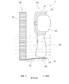
- FIG. 3 is a cross-sectional view taken along the line III-III in FIG. 1, and is a cross-sectional view showing a main part of the heat exchange module of the present embodiment.
- FIG. 4 is a diagram illustrating a schematic configuration of a heat exchange module according to the second embodiment.
- FIG. 5 is a diagram schematically showing an outline of the actual vehicle submerged road running test.
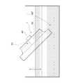
- FIG. 6 is a diagram schematically showing an outline of the bench test.
- FIG. 1 is a diagram illustrating a schematic configuration of a heat exchange module according to the first embodiment.
- 2 is a cross-sectional view taken along the line II-II in FIG.
- FIG. 3 is a cross-sectional view taken along the line III-III in FIG. 1, and is a cross-sectional view showing a main part of the
- FIG. 7 is a diagram illustrating a result of the bench test, and is a diagram illustrating a relationship between a water immersion position of the heat exchange module and a fan deformation amount.
- FIG. 8 is a diagram showing the results of unsteady fluid analysis using a three-dimensional model of the heat exchange module.
- the heat exchange module 1 includes a radiator 10 and an electric blower 20 and cools cooling water of an automobile engine.
- the heat exchange module 1 is mounted on the front side of the traveling direction of the vehicle with respect to the engine in a vehicle engine room (not shown).
- the radiator 10 and the electric blower 20 are juxtaposed along the traveling direction, and the radiator 10 is installed on the front side in the traveling direction with respect to the electric blower 20.
- the electric blower 20 is installed on the engine side (the rear side in the traveling direction) of the radiator 10.
- the back side of the paper surface of FIG. 1 is the front side
- the front side of the paper surface is the rear side
- the left side of the paper surface of FIGS. 2 and 3 is the front side
- the right side of the paper surface is the rear side.
- the vertical direction in FIG. 1 to FIG. 3 will be described as the vertical direction.
- the radiator 10 (heat exchanger) has a core portion 11 whose outer shape is formed in a rectangular shape by arranging a plurality of tubes in such a manner that the longitudinal direction of the tubes is directed in the vertical direction.
- This is a so-called vertical flow type radiator connected to a pair of tanks, that is, an upper tank 12 and a lower tank 13.
- cooling water (heat exchange medium) from the engine flows from the upper tank 12, flows in the tube of the core portion 11 from the upper side to the lower side in FIG. 1, and flows out from the lower tank 13.
- the flow direction of the cooling water in the radiator 10 is not limited to this configuration.
- the electric blower 20 mainly includes a fan shroud 30, an electric motor 40, and a cooling fan 50.
- the electric blower 20 is attached to the fan shroud 30 so that the rotation shaft of the cooling fan 50 faces the horizontal direction, and is used for cooling the core portion 11 of the radiator 10. It is designed to blow air.
- the electric blower 20 is a so-called suction type electric blower that sucks blown air from the vehicle grill side toward the engine side, that is, from the core portion 11 of the radiator 10 to the fan shroud 30 side.
- the fan shroud 30 has a rectangular shape (substantially square shape) corresponding to the core portion 11 of the radiator 10, and is made of, for example, a polypropylene resin material containing glass fiber, and is integrally formed by injection molding.
- the fan shroud 30 is disposed to face the core portion 11 of the radiator 10.
- the fan shroud 30 of the electric blower 20 is installed with the core portion 11 of the radiator 10 so that one side of the rectangular outer shape faces the installation surface.
- the fan shroud 30 is provided with a stepped cylindrical shroud ring portion 31 (accommodating portion) at a portion that becomes the outer periphery of the cooling fan 50.
- a cylindrical motor holding portion (not shown) is formed at the center of the shroud ring portion 31, and the motor holding portion extends radially and is connected to the shroud ring portion 31. (Not shown).
- the shroud ring portion 31 accommodates the cooling fan 50 in the fan shroud 30 so as to be rotatable.
- a smoothly inclined duct-shaped shroud air guide portion 32 (air guide portion) is formed, and the cooling fan 50.
- the air flow sucked by the air is efficiently guided over the entire core portion 11 of the radiator 10.
- a restricting projection 33 is formed on the inner side surface of the connection portion between the shroud ring portion 31 and the shroud air guide portion 32. The restricting protrusion 33 will be described in detail later.
- the electric motor 40 is, for example, a ferrite type DC motor, and a ferrite magnet as a stator is fixed to an inner peripheral surface of a cylindrical housing forming a main body, and an armature (coil) as a rotor is further provided inside the electric motor 40. It is mounted so that it can rotate.
- the electric motor 40 is fixed to the motor holding part of the fan shroud 30.
- the cooling fan 50 is disposed in the circumferential direction (rotation direction A centering on the rotation axis) of the boss portion 51 having a flat bottomed cylindrical shape, and a plurality of blades 52 extending radially are formed while being separated from each other. It is an axial flow fan.
- the cooling fan 50 in which the boss portion 51 and the blade 52 are integrally formed of, for example, a polypropylene resin material containing glass fiber is accommodated (enclosed) inside the shroud ring portion 31 of the fan shroud 30, and the electric motor 40.
- the rotary shaft is fixed to the rotary shaft and is rotated by the electric motor 40. That is, the cooling fan 50 is arranged in parallel with the core portion 11 of the radiator 10, and the cooling air for circulating the outside of the core portion 11 and cooling the cooling water inside is directed from the core portion 11 side to the cooling fan 50 side.
- the above-described restricting protrusion 33 is formed in a radially inward direction (a direction toward the rotation axis) from a connection portion (end portion on the core portion 11 side of the shroud ring portion 31) between the shroud ring portion 31 of the fan shroud 30 and the shroud air guide portion 32. Protruding.
- the restricting protrusion 33 is formed in a thin plate shape having the same thickness as the other portions of the fan shroud 30 and has a substantially rectangular shape.
- the regulation protrusion 33 is provided so as to protrude between the blade 52 of the cooling fan 50 and the core 11 of the radiator 10.
- a vehicle on which the heat exchange module 1 is mounted travels on a road surface with a high water level such as a flooded road in a submerged state, water may reach the cooling fan 50 through the radiator 10.
- the blade 52 receives a propulsive force when passing through the water, and the propulsive force causes the centrifugal direction end of the blade 52 to move toward the core portion 11 (progress). Deforms to the front side).
- the restriction protrusion 33 can restrict the blade 52 from being closer to the core part 11 than a predetermined position.
- this regulation projection part 33 is the state of the fan shroud 30 in the state installed so that one side of the rectangular external shape of the fan shroud 30 may oppose the installation surface.
- the amount of water that reaches the cooling fan 50 via the radiator 10 is arranged at a position that is larger than directly below the rotation axis of the cooling fan 50.
- the restricting protrusion 33 advances from the position P1 directly below the rotation axis of the cooling fan 50 (hereinafter also referred to as “directly below position P1”) to the turning rotation direction A of the cooling fan 50 and rotates the cooling fan 50. It is provided in a range P1 to P2 up to a position P2 having the same height as the center.
- the position P ⁇ b> 2 is a position advanced by 90 degrees from the direct position P ⁇ b> 1 in the turning rotation direction A of the cooling fan 50.
- the reason for determining the installation position of the restriction projection 33 will be described.
- transformation of a cooling fan is proposed similarly to the control protrusion 33 of this embodiment (for example, refer patent document 1).
- the element as such a stopper function has been provided at a position immediately below the rotating shaft of the cooling fan 50 (corresponding to the position P1 in FIG. 1). This is because when the water is submerged, the relative water level is high at the position P1 in the cooling fan 50, and the submerged area of the blade 52 is maximized. Therefore, the deformation is assumed to be maximum.
- the maximum deformation region X in which the blade 52 of the cooling fan 50 undergoes the maximum deformation due to the influence of the water flow is not a position P1 directly below the rotation axis as shown in FIG. It was found that the fan 50 exists on the side of the rotation direction A of the fan 50 and exists between the position immediately below the rotation axis and the position P2 that proceeds in the rotation direction A and has the same height as the rotation center of the cooling fan 50.
- the area of the core portion 11 of the front radiator 10 is small, so the amount of water flowing into the cooling fan 50 is only the amount of water in front of the cooling fan 50. Stays relatively small.
- the swivel rotation direction A side from the position P1 not only the portion of the core portion 11 facing the cooling fan 50 but also the portion of the core portion 11 not facing the surrounding cooling fan 50 is passed. Since water is also guided and flows in by the shroud air guiding portion 32, the amount of water flowing into the cooling fan 50 is increased as compared with the position P1.
- This position P3 is also referred to as “maximum water amount position P3” in the following description. It should be noted that the maximum water amount position P3 is 45 degrees in the turning rotation direction A from the position P1 directly below the rotation axis when the fan shroud 30 has a substantially square shape as shown in FIG.
- the range in which the amount of water increases in this way further advances to the turning rotation direction A side than the position P3, and the area of the portion of the core portion 11 that does not face the cooling fan 50 is reduced to the same as the position P1 again.
- a position P2 that is the same height as the rotation center of the cooling fan 50.
- the heat exchange module 1 can suitably prevent the cooling fan 50 from interfering with the core portion 11 of the radiator 10 and damaging the core portion 11.
- the “damage” assumed here is, for example, that the tip portion of the blade reaches the front radiator 10 due to deformation of the cooling fan 50 and is damaged by interference with the core portion 11, and in some cases, the tube of the core portion 11 is broken.
- a situation that causes The interference trace of the radiator 10 caused by the cooling fan 50 starts little by little from the position P1 immediately below the rotation axis of the cooling fan 50 as a result of the market recovery product investigation, and advances about 45 degrees from directly below the rotation direction of the cooling fan 50. It was found that the maximum was achieved at the position (maximum water amount position P3). Further, the interference trace remains in the range up to 90 degrees (position P2) in the rotation direction of the cooling fan 50.
- the above-described installation areas P1 and P2 of the restricting protrusion 33 are the maximum range for the present embodiment to exhibit the effect.
- the restricting projection 33 extends from the position P1 directly below to a position P1 that extends in the swivel rotation direction A of the cooling fan 50 and reaches a position P4 at the same height as the blade base position W immediately below the rotation axis of the blade 52 of the cooling fan 50. It is preferable to be provided at P4. Further, the restricting projection 33 is preferably provided in a range P1 to P3 from a position P1 directly below the rotation axis of the cooling fan 50 to the above-described maximum water amount position P3, and further provided at the maximum water amount position P3. preferable.
- the installation position of the restricting projection 33 the effect of suppressing the maximum displacement of the blade 52 of the cooling fan 50 can be further promoted.
- one restricting protrusion 33 is provided on the inner surface of the connection portion between the shroud ring portion 31 and the shroud air guide portion 32.
- the restricting protrusion 33 only needs to be able to restrict the blade 52 of the cooling fan 50 from being closer to the core portion 11 than the predetermined position, and is on the inner peripheral surface of the shroud ring portion 31 or the shroud air guide portion 32. You may provide in arbitrary positions.
- the heat exchange module 1A according to the second embodiment is different from that of the first embodiment in that the core 11 of the radiator 10A and the fan shroud 30A of the electric blower 20A are substantially rectangular. Different from the heat exchange module 1.
- the core portion 11 of the radiator 10A and the fan shroud 30A of the electric blower 20A are installed such that one side of the long side of the rectangular outer shape faces the installation surface.
- the restricting protrusion 33 advances from the position P1 immediately below the rotation axis of the cooling fan 50 in the turning rotation direction A of the cooling fan 50 and the rotation center of the cooling fan 50. It is provided in a range P1 to P2 up to a position P2 having the same height. Further, the restricting protrusion 33 extends from the position P1 directly below to a position P4 that proceeds in the turning rotation direction A of the cooling fan 50 and has the same height as the blade base position W immediately below the rotation axis of the blade 52 of the cooling fan 50. It is preferably provided at P1 to P4.
- the restricting projection 33 ranges from a position P1 immediately below the rotation axis of the cooling fan 50 to a maximum water amount position P3A on a line connecting the lower corner C that has advanced in the rotation direction A and the motor center. It is preferable to be provided at P3A, and more preferably at this maximum water amount position P3A.
- the fan shroud 30A when the fan shroud 30A is submerged, the area of the core portion 11 that does not face the cooling fan 50 is maximized at the maximum water amount position P3A.
- the blade 52 of the cooling fan 50 undergoes maximum deformation at a position P3 where the straight line connecting the corner portion C of the fan shroud 30 and the rotation center of the cooling fan 50 and the shroud ring portion 31 intersect. Will be described.
- a vehicle mounted with a heat exchange module equivalent to the heat exchange module 1 according to the embodiment is subjected to an actual vehicle submerged road running test in which the module is submerged so that the module is submerged.
- the inundation state in the engine compartment and engine room was observed.
- the water level rose in front of the radiator 10 and the cooling fan 50 was submerged at an angle of about 45 degrees when viewed from the side of the vehicle.
- a commercially available heat exchange module 1 (the number of cooling fans 50: 7 sheets, diameter 340 mm, 13.5 V, 80 W) was used.
- the commercially available heat exchange module 1 was dropped into the water tank in a state where it was inclined 45 degrees from the horizontal plane and the cooling fan 50 was rotationally driven as shown in FIG.
- the positional relationship (water immersion position) between the heat exchange module 1 and the water level of the water tank is as follows: (1) The water level at which the tip 1/4 of the blade 52 on the inclined lower side of the cooling fan 50 is submerged, (2) the cooling fan 50 The water level at which the tip 1/2 of the blade 52 on the lower side of the slope is submerged, (3) the water level at which the blade 52 on the lower side of the cooling fan 50 is submerged to the blade base, and (4) the boss at the center of the cooling fan 50
- FIG. 6 illustrates a state where the heat exchange module 1 is submerged to the water level (3).
- FIG. 7 The results of the bench test are shown in FIG.
- the horizontal axis of FIG. 7 shows the water immersion position, and the various water immersion positions are shown in the order of (1) ⁇ (2) ⁇ (3) ⁇ (4) from the left.
- the vertical axis in FIG. 7 indicates the amount of deformation of the cooling fan 50.
- the amount of deformation at the water immersion position (1) is the smallest, and the amount of deformation increases as the water immersion portion increases, and at the water immersion position (3), that is, the blade 52 It was confirmed that the amount of deformation was maximized when the water level was submerged. The reason why the maximum displacement is caused by the flooding at the blade base position is considered to be because the torque applied to one blade 52 is maximized in water. On the other hand, when the water immersion position transitions from (3) to (4) and becomes deeper than the blade base, the torque received by the entire cooling fan 50 is increased, so that the rotational speed is reduced and the deformation amount is confirmed to be reduced. did it.
- the cooling fan 50 is in a state where the heat exchange module 1 is submerged up to the “blade base position W (position P4) immediately below the rotation axis of the blade 52 of the cooling fan 50” in the above embodiment. It was confirmed that the maximum deformation amount.
Landscapes
- Engineering & Computer Science (AREA)
- Mechanical Engineering (AREA)
- General Engineering & Computer Science (AREA)
- Chemical & Material Sciences (AREA)
- Combustion & Propulsion (AREA)
- Physics & Mathematics (AREA)
- Thermal Sciences (AREA)
- Cooling, Air Intake And Gas Exhaust, And Fuel Tank Arrangements In Propulsion Units (AREA)
- Structures Of Non-Positive Displacement Pumps (AREA)
Abstract
熱交換モジュール1は、冷却ファン(50)のブレード(52)と熱交換器(10)のコア部(11)との間に突出するよう設けられ、前記ブレードが所定位置よりも前記コア部に近接することを規制する規制突起部(33)を備える。前記規制突起部は、ファンシュラウド(30)の矩形状の外形の一辺が設置面に対向するように設置される状態において、前記ファンシュラウドの少なくとも一部が水没した場合に前記熱交換器を介して前記冷却ファンに到達する水量が、前記冷却ファンの回転軸直下より大となる位置に配置される。
Description
本出願は、2015年12月25日に出願された日本国特許出願2015-253784号と、2016年10月31日に出願された日本国特許出願2016-212720号と、に基づくものであって、その優先権の利益を主張するものであり、その特許出願の全ての内容が、参照により本明細書に組み込まれる。
本開示は、熱交換器に冷却ファンとファンシュラウドとを備える熱交換モジュールに関する。
従来、熱交換器と、この熱交換器に並設され、熱交換器のコア部に冷却風を送風するための吸込み式の冷却ファンと、冷却ファンを収容し、冷却風がコア部を通過するように導風するファンシュラウドと、を備える熱交換モジュールが知られている。
この熱交換モジュールは、主に車両に搭載され、車両が冠水道路等の水位の高い路面を水没状態で走行すると、水が熱交換器を通って冷却ファンに達する場合がある。このとき、冷却ファンが作動していると、冷却ファンの推進力によって、冷却ファンが熱交換器側に変形し、熱交換器のコア部と干渉してコア部を損傷させ、この結果、熱交換器の冷却水漏れ、冷却ファンの破損、オーバーヒートなどの車両不具合を引き起こすことがある。特許文献1には、冷却ファンが熱交換器のコア部と干渉してコア部を損傷させるのを防止するために、冷却ファンと熱交換器のコア部との間に突出する規制突起部を冷却ファンの回転軸直下に設け、冷却ファンの変形を抑制するストッパとして機能させる構成が記載されている。
特許文献1に記載の規制突起部は、冷却ファンの変形を抑制するストッパとしての機能させるためにさらなる改善の余地があった。
本開示の目的は、冷却ファンが熱交換器のコア部に干渉してコア部にダメージを与えることを好適に防止することが可能な熱交換モジュールを提供することにある。
本開示の一態様による熱交換モジュールは、外形が矩形状で形成されるコア部を有し、コア部の内部に熱交換媒体が流れる熱交換器と、回転方向に配設された複数のブレードを有し、コア部に並設される軸流式の冷却ファンであって、コア部の外部を流通して熱交換媒体を冷却するための冷却風をコア部側から当該冷却ファン側の方向に発生する冷却ファンと、外形がコア部に対応する矩形状で形成され、コア部と対向配置されるファンシュラウドであって、冷却ファンを収容する円筒形状の収容部と、収容部からコア部側に延びて冷却風がコア部を通過するように導風するダクト状の導風部と、を有するファンシュラウドと、収容部または導風部にて冷却ファンのブレードとコア部との間に突出するよう設けられ、ブレードが所定位置よりもコア部に近接することを規制する規制突起部と、を備え、規制突起部は、ファンシュラウドの矩形状の外形の一辺が設置面に対向するように設置される状態において、ファンシュラウドの少なくとも一部が水没した場合に熱交換器を介して冷却ファンに到達する水量が、冷却ファンの回転軸直下より大となる位置に配置される。
このように規制突起部を設けることで、冷却ファンのブレードの最大変位を抑制することが可能となり、冷却ファンの変形によるラジエータのコア部への干渉不具合を好適に防ぐことができる。
以下、添付図面を参照しながら本実施形態について説明する。説明の理解を容易にするため、各図面において同一の構成要素に対しては可能な限り同一の符号を付して、重複する説明は省略する。
[第1実施形態]
図1~図3を参照して第1実施形態について説明する。図1に示すように、第1実施形態に係る熱交換モジュール1は、ラジエータ10と電動送風機20とからなり、自動車用エンジンの冷却水を冷却するものとしている。熱交換モジュール1は、図示しない車両エンジンルーム内において、エンジンに対して車両の進行方向の前側に搭載される。ラジエータ10と電動送風機20とは進行方向に沿って並設されており、ラジエータ10が電動送風機20よりも進行方向前側に設置される。電動送風機20は、ラジエータ10のエンジン側(進行方向後側)に設置されている。
図1~図3を参照して第1実施形態について説明する。図1に示すように、第1実施形態に係る熱交換モジュール1は、ラジエータ10と電動送風機20とからなり、自動車用エンジンの冷却水を冷却するものとしている。熱交換モジュール1は、図示しない車両エンジンルーム内において、エンジンに対して車両の進行方向の前側に搭載される。ラジエータ10と電動送風機20とは進行方向に沿って並設されており、ラジエータ10が電動送風機20よりも進行方向前側に設置される。電動送風機20は、ラジエータ10のエンジン側(進行方向後側)に設置されている。
なお、上記の進行方向に関しては、図1の紙面奥側が前側、紙面手前側が後側であり、図2及び図3の紙面左側が前側、紙面右側が後側である。また、以下の説明では、図1~図3の紙面上下方向を鉛直方向の上下方向として説明する。
ラジエータ10(熱交換器)は、チューブの長手方向が上下方向を向くようにして複数配列されることで外形が矩形状に形成されるコア部11を有し、このチューブの長手方向両端部が一対のタンク、即ち上タンク12および下タンク13に接続される、所謂バーチカルフロータイプのラジエータである。
ラジエータ10は、ここではエンジンからの冷却水(熱交換媒体)が上タンク12から流入し、コア部11のチューブ内を図1中の上側から下側に向けて流れ、下タンク13から流出してエンジンに戻るようになっている。なお、ラジエータ10内の冷却水の流れ方向はこの構成に限られない。
電動送風機20は、主にファンシュラウド30、電動モータ40、冷却ファン50からなり、冷却ファン50の回転軸が水平方向を向くようにファンシュラウド30に取り付けられ、ラジエータ10のコア部11に冷却用の空気を送風するようになっている。この電動送風機20は、車両のグリル側からエンジン側に向けて、即ちラジエータ10のコア部11からファンシュラウド30側に送風空気を吸引する、所謂吸込み式の電動送風機である。
ファンシュラウド30は、概略外形がラジエータ10のコア部11に対応した矩形状(略正方形状)であり、例えばガラス繊維を含有するポリプロピレン樹脂材からなり、射出成形により一体で形成されている。ファンシュラウド30は、ラジエータ10のコア部11と対向配置される。電動送風機20のファンシュラウド30は、ラジエータ10のコア部11と共に、矩形状の外形の一辺が設置面に対向するように設置される。
ファンシュラウド30は、冷却ファン50の外周となる部位に段付き円筒形状のシュラウドリング部31(収容部)を備えている。シュラウドリング部31の中心には、円筒形状のモータ保持部(図示せず)が形成されており、このモータ保持部は、放射状に延びてシュラウドリング部31に接続される複数のモータステー部(図示せず)によって支持されている。シュラウドリング部31は、冷却ファン50をファンシュラウド30内に回転可能に収容する。
シュラウドリング部31とラジエータ10のコア部11側のシュラウド30外周縁部との間には、滑らかに傾斜するダクト状のシュラウド導風部32(導風部)が形成されており、冷却ファン50によって吸引される空気流をラジエータ10のコア部11の全域にわたって効率的に導くようになっている。そして、シュラウドリング部31とシュラウド導風部32との接続部の内側面には規制突起部33が形成されている。規制突起部33については後で詳述する。
電動モータ40は、例えばフェライト式の直流モータであり、本体部をなす筒状のハウジングの内周面に固定子としてのフェライト磁石が固定され、さらにその内側に回転子としてのアーマチャ(コイル)が回転可能に装着されている。電動モータ40は、ファンシュラウド30のモータ保持部に固定されている。
冷却ファン50は、扁平有底筒状をなすボス部51の周方向(回転軸を中心とする回転方向A)に配設され、相互に離間しつつ放射状に延びる複数のブレード52が形成された軸流式のファンである。ボス部51及びブレード52が例えばガラス繊維を含有するポリプロピレン樹脂材で一体成形されてなる冷却ファン50は、ファンシュラウド30のシュラウドリング部31の内側に収容されて(内包されて)、電動モータ40の回転シャフトに固定され、電動モータ40によって回転作動されるようになっている。つまり、冷却ファン50は、ラジエータ10のコア部11に並設され、コア部11の外部を流通して内部の冷却水を冷却するための冷却風をコア部11側から冷却ファン50側の方向Bに発生させる。
前述の規制突起部33は、ファンシュラウド30のシュラウドリング部31とシュラウド導風部32との接続部(シュラウドリング部31のコア部11側端部)から径内方向(回転軸に向かう方向)に突出している。規制突起部33は、ファンシュラウド30の他の部分と同様な厚さの薄板状に形成されて略矩形形状をなしている。
図3に示すように、規制突起部33は、冷却ファン50のブレード52と、ラジエータ10のコア部11との間に突出するよう設けられる。上述のように、熱交換モジュール1が搭載される車両が冠水道路等の水位の高い路面を水没状態で走行すると、水がラジエータ10を通って冷却ファン50に達する場合がある。このとき、冷却ファン50が作動していると、ブレード52が水中を通過する際にコア部11側に推進力を受け、この推進力によってブレード52の遠心方向端部がコア部11側(進行方向前側)に変形する。規制突起部33は、このような冷却ファン50のブレード52に変形が生じたときに、ブレード52が所定位置よりもコア部11に近接することを規制することができる。
そして、特に本実施形態では、この規制突起部33は、図1に示すように、ファンシュラウド30の矩形状の外形の一辺が設置面に対向するように設置される状態において、ファンシュラウド30の少なくとも一部が水没した場合に、ラジエータ10を介して冷却ファン50に到達する水量が、冷却ファン50の回転軸直下より大となる位置に配置されている。
より詳細には、規制突起部33は、冷却ファン50の回転軸直下の位置P1(以下では「直下位置P1」とも表記する)から、冷却ファン50の旋回回転方向Aに進み冷却ファン50の回転中心と同じ高さとなる位置P2までの範囲P1~P2に設けられる。位置P2は、図1の例では、直下位置P1から冷却ファン50の旋回回転方向Aに90度進んだ位置である。ここで、このように規制突起部33の設置位置を定める理由について説明する。
従来より、本実施形態の規制突起部33と同様に、冷却ファンの変形を抑制するストッパを設ける構成は提案されている(例えば特許文献1参照)。しかし、従来はこのようなストッパ機能としての要素は、冷却ファン50の回転軸の直下の位置(図1の位置P1に相当)に設けられていた。水没した場合には、冷却ファン50の中で位置P1が相対的な水位が高く、ブレード52の水没面積が最大となることから、変形も最大となると想定されていたためである。
しかしながら、鋭意研究の結果、水流の影響によって冷却ファン50のブレード52に最大変形が生じる最大変形領域Xは、図1に示すように、回転軸直下の位置P1ではなく、この位置P1よりも冷却ファン50の旋回回転方向A側であり、回転軸直下から旋回回転方向Aに進み冷却ファン50の回転中心と同じ高さとなる位置P2までの間に存在することが見出された。
回転軸直下の位置P1においては、図2に矢印Bで示すように、前方のラジエータ10のコア部11の面積が小さいため、冷却ファン50に流入する水量は、冷却ファン50の前方の水量だけに留まり、相対的に少量となる。これに対して、位置P1よりも旋回回転方向A側では、冷却ファン50が対向するコア部11の部分だけでなく、その周囲の冷却ファン50と対向していないコア部11の部分を通った水もシュラウド導風部32によって誘導されて流入するため、冷却ファン50に流入する水量は、位置P1と比較して増大する。
特に、ファンシュラウド30のコーナー部C(位置P1から旋回回転方向Aに進んだ方向にある、設置面と接触する角部)と、冷却ファン50の回転中心とを結んだ直線上の位置、すなわちこの直線とシュラウドリング部31とが交差する位置P3では、図3に矢印Bで示すように、冷却ファン50と対向していないコア部11の部分の面積が最大となるので、冷却ファン50に流入する水量が最大となる。すなわち、冷却ファン50のブレード52に最大変形が生じる最大変形領域Xは位置P3に存在し、この位置P3に規制突起部33を設けるのがストッパ機能としての効果を最も発揮できると考えられる。この位置P3を以降の説明では「水量最大位置P3」とも表記する。なお、このような水量最大位置P3は、ファンシュラウド30が図1に示すような略正方形状の場合には、回転軸直下の位置P1から旋回回転方向Aに45度の位置となる。
そして、このように水量が増大する範囲は、位置P3よりもさらに旋回回転方向A側に進み、冷却ファン50と対向していないコア部11の部分の面積が再び位置P1と同等まで低減する、冷却ファン50の回転中心と同じ高さとなる位置P2までである。なお、この位置P2よりさらに旋回回転方向Aに進む領域(すなわち位置P1から90度以上進んだ位置)を水量増大範囲に含まない理由は、これらの領域まで冷却ファン50が水没する状況とは冷却ファン50の回転中心に配置される電動モータ40も水没している状況であり、冷却ファン50の回転が困難になるからである。
従って、上記の回転軸直下の位置P1から旋回回転方向Aに進み冷却ファン50の回転中心と同じ高さとなる位置P2までの領域P1~P2に規制突起部33を設けることで、水量が冷却ファン50の回転軸直下より大となる位置に規制突起部33が配置されることとなる。このように規制突起部33を設けることで、冷却ファン50のブレード52の最大変位を抑制することが可能となり、冷却ファン50の変形によるラジエータ10のコア部11への干渉不具合を好適に防ぐことができる。この結果、本実施形態に係る熱交換モジュール1は、冷却ファン50がラジエータ10のコア部11に干渉してコア部11にダメージを与えることを好適に防止することが可能となる。
なお、ここで想定する「ダメージ」とは、例えば、冷却ファン50の変形によって翼の先端部分が前方のラジエータ10に達し、コア部11と干渉して傷付け、場合によってはコア部11のチューブ破損を引き起こす状況をいう。このような冷却ファン50によるラジエータ10の干渉痕は、市場回収品調査の結果、冷却ファン50の回転軸直下の位置P1から少しずつ始まり、直下から冷却ファン50の回転方向に約45度進んだ位置(水量最大位置P3)で最大となることが判った。また、その干渉痕は、冷却ファン50の回転方向に90度(位置P2)までの範囲に留まっている。すなわち、回転軸直下から回転方向に90度までの範囲(領域P1~P2)、中でも約45度の位置(水量最大位置P3)での干渉(傷付)が著しいことが判った。チューブ破損が発生するとラジエータ10内の冷却水が漏れ、十分な冷却水がエンジンに戻されなくなり、この結果エンジンのオーバーヒートを発生させる場合がある。
また、上述した規制突起部33の設置領域P1~P2は、本実施形態が効果を発揮し得るための最大範囲である。規制突起部33は、上述の直下位置P1から、冷却ファン50の旋回回転方向Aに進み冷却ファン50のブレード52の回転軸直下の翼元位置Wと同じ高さとなる位置P4までの範囲P1~P4に設けられるのが好ましい。また、規制突起部33は、冷却ファン50の回転軸直下の直下位置P1から上述の水量最大位置P3までの範囲P1~P3に設けられるのがより好ましく、水量最大位置P3に設けられるのがさらに好ましい。このように規制突起部33の設置位置をさらに限定することによって、冷却ファン50のブレード52の最大変位を抑制する効果をさらに促進できる。
また、規制突起部33は、シュラウドリング部31とシュラウド導風部32との接続部の内側面に1個が設けられる。規制突起部33の設置個数を最小限にすることで、ファンシュラウド30への冷却ファン50の組み付け容易性を維持できると共に、製造コスト増加を抑制できる。
なお、規制突起部33は、冷却ファン50のブレード52が所定位置よりもコア部11に近接することを規制することができればよく、シュラウドリング部31またはシュラウド導風部32の内周面上の任意の位置に設けてもよい。
[第2実施形態]
図4を参照して第2実施形態を説明する。図4に示すように、第2実施形態に係る熱交換モジュール1Aは、ラジエータ10Aのコア部11、及び電動送風機20Aのファンシュラウド30Aの形状が略長方形状である点で、第1実施形態の熱交換モジュール1と異なる。ラジエータ10Aのコア部11、及び電動送風機20Aのファンシュラウド30Aは、長方形状の外形のうち長辺の一辺が設置面に対向するように設置される。
図4を参照して第2実施形態を説明する。図4に示すように、第2実施形態に係る熱交換モジュール1Aは、ラジエータ10Aのコア部11、及び電動送風機20Aのファンシュラウド30Aの形状が略長方形状である点で、第1実施形態の熱交換モジュール1と異なる。ラジエータ10Aのコア部11、及び電動送風機20Aのファンシュラウド30Aは、長方形状の外形のうち長辺の一辺が設置面に対向するように設置される。
第2実施形態でも、第1実施形態と同様に、規制突起部33は、冷却ファン50の回転軸直下の直下位置P1から、冷却ファン50の旋回回転方向Aに進み冷却ファン50の回転中心と同じ高さとなる位置P2までの範囲P1~P2に設けられる。また、規制突起部33は、上述の直下位置P1から、冷却ファン50の旋回回転方向Aに進み冷却ファン50のブレード52の回転軸直下の翼元位置Wと同じ高さとなる位置P4までの範囲P1~P4に設けられるのが好ましい。さらに、規制突起部33は、冷却ファン50の回転軸直下の位置P1から、旋回回転方向Aに進んだ下方の角部Cとモータ中心とを結んだ線上の水量最大位置P3Aまでの範囲P1~P3Aに設けられるのが好ましく、この水量最大位置P3Aに設けられるのがさらに好ましい。
第2実施形態の熱交換モジュール1Aにおいても、ファンシュラウド30Aが水没したときには水量最大位置P3Aにおいて冷却ファン50と対向していないコア部11の部分の面積が最大となるので、冷却ファン50に流入する水量が最大となる。なお、このような水量最大となる位置P3Aは、ファンシュラウド30が図4に示すような略長方形状の場合には、冷却ファン50の回転中心から回転軸直下の位置P1まで距離L1と、ファンシュラウド30の設置面と接する一辺のうちこの位置P1から角部までの長さL2とを用いて、ファンシュラウド30のから旋回回転方向Aに角度θ=arctan(L2/L1)だけ進んだ位置となる。
以下、実施例を挙げて上記実施形態についてより具体的に説明する。ただし、本発明は以下の実施例に限定されるものではない。以下の実施例では、ファンシュラウド30のコーナー部Cと冷却ファン50の回転中心とを結んだ直線とシュラウドリング部31とが交差する位置P3において、冷却ファン50のブレード52に最大変形が生じる点について説明する。
まず、図5に示すように、実施形態に係る熱交換モジュール1と同等の熱交換モジュールを搭載する車両で、モジュールが水没する程度の冠水路を走行する実車冠水路走行試験を行い、エンコパ(エンジンコンパートメント、エンジンルーム)内への浸水状態を観察した。この試験の結果、ラジエータ10の前方で水位が上昇し、冷却ファン50に対しては、車両の側面から視たときに約45度の角度で浸水してくることが判った。
そこで、上記の実車冠水路走行試験で観察された、側面視45度の角度で浸水する実車での浸水状態を模擬したベンチ試験を考案し、このベンチ試験で冷却ファン50の浸水位置(深さ)と、冷却ファン50の変形量との関係を計測した。
ベンチ試験には、市販品の熱交換モジュール1(冷却ファン50の枚数:7枚、直径340mm、13.5V、80W)を用いた。この市販品の熱交換モジュール1を、図6に示すように水平面から45度傾斜させ、かつ、冷却ファン50を回転駆動させている状態で、水槽に落とし込んだ。熱交換モジュール1と水槽の水位との位置関係(水浸位置)は、(1)冷却ファン50の傾斜下方側のブレード52の先端1/4の部分が浸水する水位、(2)冷却ファン50の傾斜下方側のブレード52の先端1/2の部分が浸水する水位、(3)冷却ファン50の傾斜下方側のブレード52が翼元まで浸水する水位、(4)冷却ファン50の中央のボス部51及びこのボス部51に連結される電動モータ40が浸水する水位、の4種類とした。そして、各種類の水浸位置における冷却ファン50の変形量を計測した。図6には、上記(3)の水位まで熱交換モジュール1を水没させている状態を例示している。
ベンチ試験の結果を図7に示す。図7の横軸は水浸位置を示し、上記の各種の水浸位置を左から(1)→(2)→(3)→(4)の順で示している。図7の縦軸は冷却ファン50の変形量を示す。
図7に示すように、水浸位置(1)における変形量が最小であり、水浸部分が増加するにつれて変形量が増大してゆき、水浸位置(3)において、すなわちブレード52が翼元まで浸水する水位のとき変形量が最大となることが確認できた。翼元位置の浸水で最大変位となるのは、水中で1枚のブレード52に加わるトルクが最大となるためであると考えられる。一方、水浸位置が(3)から(4)へ遷移して翼元よりも深くなると、冷却ファン50全体が受けるトルクが増大することで回転数が低下し、変形量は減少することが確認できた。したがって、ベンチ試験の結果から、上記実施形態の「冷却ファン50のブレード52の回転軸直下の翼元位置W(位置P4)」まで熱交換モジュール1が浸水している状態のときに冷却ファン50が変形量最大となることを確認できた。
次に、ベンチ試験の結果に基づいて、この変形量最大となる翼元の水位までモジュールが水浸しているとの条件を設定し、熱交換モジュール1の三次元モデルを用いて水と空気の二層流での非定常流体解析を実施した。解析結果を図8に示す。図8に示すように、三次元モデルを用いた解析結果では、上記実施形態と同様に、ファンシュラウド30のコーナー部Cと冷却ファン50の回転中心とを結んだ直線とシュラウドリング部31とが交差する位置P3において、冷却ファン50のブレード52に最大変形が生じていることが確認できた。
以上、具体例を参照しつつ本実施形態について説明した。しかし、本開示はこれらの具体例に限定されるものではない。これら具体例に、当業者が適宜設計変更を加えたものも、本開示の特徴を備えている限り、本開示の範囲に包含される。前述した各具体例が備える各要素およびその配置、条件、形状などは、例示したものに限定されるわけではなく適宜変更することができる。前述した各具体例が備える各要素は、技術的な矛盾が生じない限り、適宜組み合わせを変えることができる。
Claims (6)
- 外形が矩形状で形成されるコア部(11)を有し、前記コア部の内部に熱交換媒体が流れる熱交換器(10,10A)と、
回転方向に配設された複数のブレード(52)を有し、前記コア部に並設される軸流式の冷却ファン(50)であって、前記コア部の外部を流通して前記熱交換媒体を冷却するための冷却風を前記コア部側から当該冷却ファン側の方向(B)に発生する冷却ファンと、
外形が前記コア部に対応する矩形状で形成され、前記コア部と対向配置されるファンシュラウド(30,30A)であって、前記冷却ファンを収容する円筒形状の収容部(31)と、前記収容部から前記コア部側に延びて前記冷却風が前記コア部を通過するように導風するダクト状の導風部(32)と、を有するファンシュラウドと、
前記収容部または前記導風部にて前記冷却ファンの前記ブレードと前記コア部との間に突出するよう設けられ、前記ブレードが所定位置よりも前記コア部に近接することを規制する規制突起部(33)と、
を備え、
前記規制突起部は、前記ファンシュラウドの矩形状の外形の一辺が設置面に対向するように設置される状態において、前記ファンシュラウドの少なくとも一部が水没した場合に前記熱交換器を介して前記冷却ファンに到達する水量が、前記冷却ファンの回転軸直下より大となる位置に配置される、
熱交換モジュール(1,1A)。 - 前記規制突起部は、前記冷却ファンの回転軸直下の直下位置(P1)から、前記冷却ファンの旋回回転方向(A)に進み前記冷却ファンの回転中心と同じ高さとなる位置(P2)までの範囲(P1~P2)に設けられる、
請求項1に記載の熱交換モジュール。 - 前記冷却ファンは、回転軸まわりに配置され、前記複数のブレードの翼元と連結されるボス部(51)を有し、
前記規制突起部は、前記直下位置(P1)から、前記冷却ファンの旋回回転方向(A)に進み前記冷却ファンの前記ブレードの回転軸直下の翼元位置(W)と同じ高さとなる位置(P4)までの範囲(P1~P4)に設けられる、
請求項2に記載の熱交換モジュール。 - 前記規制突起部は、前記直下位置(P1)から前記旋回回転方向(A)に進んだ方向にある、前記設置面と接している前記ファンシュラウドの角部(C)と、前記冷却ファンの回転中心とを結んだ直線上の位置であり、前記ファンシュラウドの水没時に前記冷却ファンに流れる水量が最大となる水量最大位置(P3,P3A)と、前記直下位置(P1)との間の範囲(P1~P3,P3A)に設けられる、
請求項3に記載の熱交換モジュール。 - 前記規制突起部は、前記水量最大位置(P3,P3A)に設けられる、
請求項4に記載の熱交換モジュール。 - 前記規制突起部は、前記収容部または前記導風部に1個が設けられる、
請求項1~5のいずれか1項に記載の熱交換モジュール。
Priority Applications (2)
| Application Number | Priority Date | Filing Date | Title |
|---|---|---|---|
| US16/063,840 US10837346B2 (en) | 2015-12-25 | 2016-12-19 | Heat exchange module |
| CN201680075243.9A CN108431380B (zh) | 2015-12-25 | 2016-12-19 | 热交换组件 |
Applications Claiming Priority (4)
| Application Number | Priority Date | Filing Date | Title |
|---|---|---|---|
| JP2015-253784 | 2015-12-25 | ||
| JP2015253784 | 2015-12-25 | ||
| JP2016-212720 | 2016-10-31 | ||
| JP2016212720A JP6418221B2 (ja) | 2015-12-25 | 2016-10-31 | 熱交換モジュール |
Publications (1)
| Publication Number | Publication Date |
|---|---|
| WO2017110733A1 true WO2017110733A1 (ja) | 2017-06-29 |
Family
ID=59090339
Family Applications (1)
| Application Number | Title | Priority Date | Filing Date |
|---|---|---|---|
| PCT/JP2016/087752 Ceased WO2017110733A1 (ja) | 2015-12-25 | 2016-12-19 | 熱交換モジュール |
Country Status (1)
| Country | Link |
|---|---|
| WO (1) | WO2017110733A1 (ja) |
Citations (5)
| Publication number | Priority date | Publication date | Assignee | Title |
|---|---|---|---|---|
| JPS5310029U (ja) * | 1976-07-09 | 1978-01-27 | ||
| JP2000345845A (ja) * | 1999-06-04 | 2000-12-12 | Fuji Heavy Ind Ltd | ラジエータの冷却構造 |
| JP2008038776A (ja) * | 2006-08-07 | 2008-02-21 | Denso Corp | 熱交換装置 |
| JP2009109103A (ja) * | 2007-10-31 | 2009-05-21 | Denso Corp | 熱交換モジュール |
| US20090159020A1 (en) * | 2007-12-19 | 2009-06-25 | Deere & Company | Damage Protected Motor Vehicle Fan |
-
2016
- 2016-12-19 WO PCT/JP2016/087752 patent/WO2017110733A1/ja not_active Ceased
Patent Citations (5)
| Publication number | Priority date | Publication date | Assignee | Title |
|---|---|---|---|---|
| JPS5310029U (ja) * | 1976-07-09 | 1978-01-27 | ||
| JP2000345845A (ja) * | 1999-06-04 | 2000-12-12 | Fuji Heavy Ind Ltd | ラジエータの冷却構造 |
| JP2008038776A (ja) * | 2006-08-07 | 2008-02-21 | Denso Corp | 熱交換装置 |
| JP2009109103A (ja) * | 2007-10-31 | 2009-05-21 | Denso Corp | 熱交換モジュール |
| US20090159020A1 (en) * | 2007-12-19 | 2009-06-25 | Deere & Company | Damage Protected Motor Vehicle Fan |
Similar Documents
| Publication | Publication Date | Title |
|---|---|---|
| JP2014015862A (ja) | 冷却ファン装置 | |
| US11286953B2 (en) | Blower | |
| JP6394409B2 (ja) | 送風装置 | |
| JP6418221B2 (ja) | 熱交換モジュール | |
| KR102234339B1 (ko) | 차량용 팬 슈라우드 | |
| KR101693348B1 (ko) | 액티브 에어 플랩 | |
| JP2009109103A (ja) | 熱交換モジュール | |
| US20150349608A1 (en) | Axial Gap Motor | |
| CN105579713B (zh) | 送风装置 | |
| WO2017110733A1 (ja) | 熱交換モジュール | |
| JP6652034B2 (ja) | 熱交換モジュール | |
| KR102222129B1 (ko) | 전동기 | |
| JP2017120172A5 (ja) | ||
| US11448077B2 (en) | Method for manufacturing turbo fan | |
| CN106460634B (zh) | 风扇罩 | |
| KR102335896B1 (ko) | 모터 냉각용 공기 흐름 구조가 개선된 냉각팬 슈라우드 장치 | |
| JP2009221928A (ja) | シロッコファン及びその製造方法 | |
| CN111919368A (zh) | 马达 | |
| CN204947810U (zh) | 马达以及车载设备 | |
| KR102613730B1 (ko) | 팬 쉬라우드 조립체 | |
| JP2008038776A (ja) | 熱交換装置 | |
| JP2018057153A (ja) | モータの冷却機構 | |
| KR20170025127A (ko) | 차량용 팬 슈라우드 | |
| JP7666166B2 (ja) | ファン装置 | |
| KR20150071845A (ko) | 쿨링팬 |
Legal Events
| Date | Code | Title | Description |
|---|---|---|---|
| 121 | Ep: the epo has been informed by wipo that ep was designated in this application |
Ref document number: 16878622 Country of ref document: EP Kind code of ref document: A1 |
|
| NENP | Non-entry into the national phase |
Ref country code: DE |
|
| 122 | Ep: pct application non-entry in european phase |
Ref document number: 16878622 Country of ref document: EP Kind code of ref document: A1 |