WO2017110363A1 - Système et procédé de prévention de fuites d'informations - Google Patents
Système et procédé de prévention de fuites d'informations Download PDFInfo
- Publication number
- WO2017110363A1 WO2017110363A1 PCT/JP2016/085003 JP2016085003W WO2017110363A1 WO 2017110363 A1 WO2017110363 A1 WO 2017110363A1 JP 2016085003 W JP2016085003 W JP 2016085003W WO 2017110363 A1 WO2017110363 A1 WO 2017110363A1
- Authority
- WO
- WIPO (PCT)
- Prior art keywords
- information
- security policy
- user
- server
- client terminal
- Prior art date
Links
Images


Classifications
-
- H—ELECTRICITY
- H04—ELECTRIC COMMUNICATION TECHNIQUE
- H04L—TRANSMISSION OF DIGITAL INFORMATION, e.g. TELEGRAPHIC COMMUNICATION
- H04L63/00—Network architectures or network communication protocols for network security
- H04L63/10—Network architectures or network communication protocols for network security for controlling access to devices or network resources
- H04L63/105—Multiple levels of security
-
- G—PHYSICS
- G06—COMPUTING; CALCULATING OR COUNTING
- G06F—ELECTRIC DIGITAL DATA PROCESSING
- G06F21/00—Security arrangements for protecting computers, components thereof, programs or data against unauthorised activity
- G06F21/50—Monitoring users, programs or devices to maintain the integrity of platforms, e.g. of processors, firmware or operating systems
- G06F21/55—Detecting local intrusion or implementing counter-measures
- G06F21/554—Detecting local intrusion or implementing counter-measures involving event detection and direct action
-
- G—PHYSICS
- G06—COMPUTING; CALCULATING OR COUNTING
- G06F—ELECTRIC DIGITAL DATA PROCESSING
- G06F21/00—Security arrangements for protecting computers, components thereof, programs or data against unauthorised activity
- G06F21/60—Protecting data
-
- H—ELECTRICITY
- H04—ELECTRIC COMMUNICATION TECHNIQUE
- H04L—TRANSMISSION OF DIGITAL INFORMATION, e.g. TELEGRAPHIC COMMUNICATION
- H04L41/00—Arrangements for maintenance, administration or management of data switching networks, e.g. of packet switching networks
- H04L41/08—Configuration management of networks or network elements
- H04L41/0893—Assignment of logical groups to network elements
-
- H—ELECTRICITY
- H04—ELECTRIC COMMUNICATION TECHNIQUE
- H04L—TRANSMISSION OF DIGITAL INFORMATION, e.g. TELEGRAPHIC COMMUNICATION
- H04L41/00—Arrangements for maintenance, administration or management of data switching networks, e.g. of packet switching networks
- H04L41/28—Restricting access to network management systems or functions, e.g. using authorisation function to access network configuration
-
- H—ELECTRICITY
- H04—ELECTRIC COMMUNICATION TECHNIQUE
- H04L—TRANSMISSION OF DIGITAL INFORMATION, e.g. TELEGRAPHIC COMMUNICATION
- H04L63/00—Network architectures or network communication protocols for network security
- H04L63/10—Network architectures or network communication protocols for network security for controlling access to devices or network resources
- H04L63/102—Entity profiles
-
- H—ELECTRICITY
- H04—ELECTRIC COMMUNICATION TECHNIQUE
- H04L—TRANSMISSION OF DIGITAL INFORMATION, e.g. TELEGRAPHIC COMMUNICATION
- H04L63/00—Network architectures or network communication protocols for network security
- H04L63/14—Network architectures or network communication protocols for network security for detecting or protecting against malicious traffic
- H04L63/1408—Network architectures or network communication protocols for network security for detecting or protecting against malicious traffic by monitoring network traffic
- H04L63/1416—Event detection, e.g. attack signature detection
-
- H—ELECTRICITY
- H04—ELECTRIC COMMUNICATION TECHNIQUE
- H04L—TRANSMISSION OF DIGITAL INFORMATION, e.g. TELEGRAPHIC COMMUNICATION
- H04L63/00—Network architectures or network communication protocols for network security
- H04L63/20—Network architectures or network communication protocols for network security for managing network security; network security policies in general
-
- G—PHYSICS
- G06—COMPUTING; CALCULATING OR COUNTING
- G06F—ELECTRIC DIGITAL DATA PROCESSING
- G06F21/00—Security arrangements for protecting computers, components thereof, programs or data against unauthorised activity
- G06F21/50—Monitoring users, programs or devices to maintain the integrity of platforms, e.g. of processors, firmware or operating systems
- G06F21/55—Detecting local intrusion or implementing counter-measures
- G06F21/56—Computer malware detection or handling, e.g. anti-virus arrangements
Definitions
- This disclosure relates to information leakage prevention technology for preventing information leakage due to malware, for example.
- Patent Literature As a technique for preventing damage by blocking the connection from an infected client machine to the C & C server or isolating the infected client machine from the network when malware infection is detected by anti-malware software, for example, Patent Literature There is a technique described in 1.
- Japanese Patent Application Laid-Open No. 2004-151561 describes a technique for blocking a packet destined for a specific address using a firewall device and a relay device when a traffic abnormality is detected.
- Patent Document 1 the technique described in Patent Document 1 is based on the assumption that a firewall device and a relay device exist between an external network and a client machine, and the client machine is installed in a specific internal network where the firewall device and the relay device exist. There is a need to. For this reason, information leakage from client machines located outside the internal network cannot be prevented.
- Patent Document 1 uses a firewall device and a relay device to uniformly limit access to the outside. For this reason, only the same level of countermeasures can be taken for all client machines existing in the internal network. In addition, it is impossible to flexibly cope with such a case that the security strength is changed by a user who uses each client machine, a network connection is permitted within a range that is recognized as safe, and the use restriction of the user is reduced.
- the present disclosure employs, for example, the configuration described in the claims.
- the present specification includes a plurality of means for solving the above-described problems.
- a client terminal having a client processing unit that performs network control in accordance with an acquired security policy and the client terminal are used.
- a user database for storing information about the user to perform
- a security policy database for storing a security policy that defines network control content for each user attribute, and the security policy based on the user attribute and the time at which the security policy is distributed.
- An information leakage prevention system comprising: a management server having a server processing unit that selects and transmits the selected security policy to the corresponding client terminal.
- the present disclosure it is possible to block information transmission from the client terminal to the C & C server or to isolate the client terminal from the network even in a network where there is no firewall device or relay device. Moreover, according to this indication, the strength of a security policy can be changed according to the attribute of the user of a client terminal. Problems, configurations, and effects other than those described above will become apparent from the following description of embodiments.
- FIG. 1 is a diagram illustrating an overall configuration of a system according to Embodiment 1.
- FIG. The figure explaining the structure of the data stored in the user database (Example 1).
- FIG. 4 is a diagram for explaining the structure of data stored in a security policy database (Example 1).
- 10 is a flowchart for explaining a processing procedure when starting a client machine (first embodiment).
- 10 is a flowchart for explaining a processing procedure of the management server when the client machine is activated (first embodiment).
- the flowchart explaining the process sequence of the client machine at the time of malware infection Example 1).
- the flowchart explaining the process sequence of the management server at the time of malware infection Example 1).
- FIG. 3 is a diagram illustrating an overall configuration of a system according to a second embodiment.
- FIG. 6 is a diagram for explaining the structure of data stored in a security policy database (second embodiment).
- the flowchart explaining the processing procedure of the client machine at the time of malware infection (Example 2).
- the flowchart explaining the process sequence of the management server at the time of malware infection (Example 2).
- FIG. 10 is a diagram illustrating an overall configuration of a system according to a third embodiment.
- FIG. 10 is a diagram for explaining the structure of data stored in a security policy database (third embodiment).
- a flowchart explaining the processing procedure of the client machine at the time of malware infection (Example 3).
- the flowchart explaining the process sequence of the management server at the time of malware infection (Example 3).
- FIG. 1 shows an overall configuration of an information leakage prevention system 100 according to the present embodiment.
- the information leakage prevention system 100 is a system that controls the client machine's network connection and access to the C & C server by cooperation between the client machine and the management server, and prevents information leakage due to malware infection.
- the information leakage prevention system 100 includes a management server 106 and client machines 103 and 111.
- the management server 106 and the client machines 103 and 111 are connected through the network 102.
- FIG. 1 only the client machines 103 and 111 are shown, but the number of client machines is arbitrary.
- Each of the client machines 103 and 111 has a computer as a basic configuration and includes a CPU, a RAM, a ROM, a hard disk device, a network interface, a display device, and the like.
- the anti-malware software 104 and the client processing unit 114 that are provided with functions through execution of programs by the CPU are installed in the client machines 103 and 111.
- the anti-malware software 104 is a program that detects malware infection.
- the client processing unit 114 includes a user information transmission function, a malware detection information transmission function, and a network control function.
- the user information transmission function is used for transmitting user information
- the malware detection information transmission function is used for transmission of malware detection information
- the network control function controls connection or disconnection with a network or the like.
- the management server 106 has a computer as a basic configuration and includes a CPU, a RAM, a ROM, a hard disk device, a network interface, and the like. A display device is also connected to the management server 106 as necessary.
- the management server 106 according to the present embodiment includes a user database (database) 107, a security policy database (DB) 109, and a server processing unit 115.
- the server processing unit 115 provides a user information management function, a security policy management function, and a security policy transmission function through execution of a program by the CPU.
- the user information management function manages the user database 107
- the security policy management function manages the security policy database 109
- the security policy transmission function is used for transmission of the security policy.
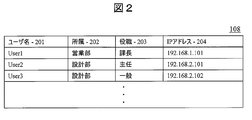
- the user database 107 stores data 108 such as the user name (or identifier), affiliation, title, and IP address of the client machine of each user. In this specification, these pieces of information are collectively referred to as “information about the user”. Also, the user name (or identifier), affiliation, and title of each user are collectively referred to as “user information”. In this embodiment, the affiliation, title, and policy distribution time of each user are also collectively referred to as “attributes”.
- the security policy database 109 stores data 110 describing affiliation, title, policy distribution time, policy application operation, and the like.
- the client machines 103 and 111 activated by the user transmit user information (user name, affiliation, title) registered in advance and the IP address (at the time of activation) of the own machine to the management server 106.
- user information user name, affiliation, title
- IP address at the time of activation
- the client machines 103 and 111 indicate the changed user name, affiliation, title, and IP address (after update) to the management server 106.
- the management server 106 receives information on the user name, affiliation, title, and IP address of each user from the client machines 103 and 111, the management server 106 stores them in the user database 107.
- the client machine 103 when the client machine 103 is infected with malware, the client machine 103 transmits malware detection information output from the anti-malware software 104 to the management server 106.
- the malware detection information includes detection date and time and C & C server information that is a communication destination of the malware.
- the management server 106 When the management server 106 receives malware detection information, the management server 106 extracts C & C server information from the detection information. Next, the management server 106 specifies the current time at which the policy is distributed, and searches the data 110 stored in the security policy database 109 at the specified current time. Here, the management server 106 selects a security policy registered for a combination of affiliation and post related to the current time. In addition, the management server 106 extracts each IP address corresponding to the combination of affiliation and title related to the current time from the data 108 stored in the user database 107, and sends each IP address to the IP address. A security policy and C & C server information corresponding to is transmitted. The transmission destination here is not limited to the client machine 103 infected with malware. In the case of FIG. 1, both of the client machines 103 and 111 are transmission destinations of the security policy and C & C server information.
- the client machines 103 and 111 that have received the security policy and the C & C server information disconnect the connection with the C & C server 101 or the network 102 according to the content of the received security policy.
- the client machine 103 disconnects the connection with the network 102
- the client machine 111 disconnects only the connection with the C & C server 101 (maintains the connection with the network).
- FIG. 2 shows a structural example of the data 108 stored in the user database 107.
- the user database 107 includes, as data items, a user name 201, an affiliation 202, a job title 203, and an IP address 204 of the client machine for each user. These pieces of information are transmitted from the client machines 103 and 111 to the management server 106 at the time of activation, and are stored in corresponding item positions by the management server 106.
- the management server 106 When the received user name 201 is already registered in the user database 107, the management server 106 newly receives information on the affiliation 202, post 203, and IP address 204 associated with the existing user name 201. Overwrite with. When the received user name 201 is not registered in the user database 107, the management server 106 stores the received user name 201, affiliation 202, title 203, and IP address 204 in a new line. The administrator of the management server 106 can delete unnecessary rows from the user database 107.
- FIG. 3 shows an example of the structure of the data 110 stored in the security policy database 109.
- the security policy database 109 has, as data items, an affiliation 301, a post 302, a policy distribution time 303, and a policy application operation 304.
- the management server 106 searches the security policy database 109 at the current time for distributing the policy, and includes the user (affiliation 301) included in the time 303 including the current time. And a security policy (operation 304 at the time of policy application) to be applied is selected.
- the management server 106 When the combination of the affiliation 301 and the post 302 associated with the time 303 including the current time at which the policy is distributed is not registered in the security policy database 109, the management server 106 indicates that the operation 304 at the time of applying the policy is “prohibit network connection”. And distribute the policy to all managed client machines. “Prohibit network connection” is the most severe operation. The administrator of the management server 106 can set the operation 304 when applying the policy for each combination of the affiliation 301, the post 302, and the time 303, and can change or delete the data even after the setting.
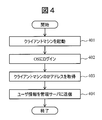
- FIG. 4 shows a processing procedure executed by the client machines 103 and 111 when the client machine is started.
- the client processing unit 114 logs in to an OS (Operation System) (step 402).
- the client processing unit 114 acquires its own IP address (step 403).
- the client processing unit 114 transmits the own IP address acquired in step 403 and user information (user name, affiliation, job title information) registered in advance to the management server 106 (step 404). ).
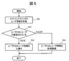
- FIG. 5 shows a processing procedure executed by the management server 106 when the client machine is activated.
- the server processing unit 115 of the management server 106 receives the IP address and user information from the client machines 103 and 111 (step 501).
- the user information here is the user information transmitted in step 404.
- the server processing unit 115 checks whether or not the user name included in the received user information is registered in the user database 107 (step 502).
- the server processing unit 115 overwrites each information of the affiliation 202, post 203, and IP address 204 associated with the user name with the contents of the received user information. Update (step 503).
- the server processing unit 115 newly registers the content of the received user information in the user database 107 (step 504).
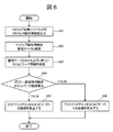
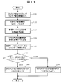
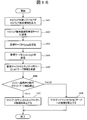
- FIG. 6 shows a processing procedure executed on the client machine 103 infected with malware. Malware infection is detected by the anti-malware software 104 running on the client machine 103. When detecting malware infection, the anti-malware software 104 outputs malware detection information (step 601). Subsequently, the client processing unit 114 of the client machine 103 transmits malware detection information to the management server 106 (step 602).
- the client processing unit 114 receives the security policy and C & C server information from the management server 106 (step 603).
- the client processing unit 114 confirms whether the operation at the time of applying the policy included in the received security policy is “network connection prohibited” or “C & C server connection prohibited” (step 604). If the operation at the time of applying the policy is “network connection prohibited”, the client processing unit 114 disconnects the connection to the network 102 and isolates itself from the network (step 605). On the other hand, when the operation at the time of applying the policy is “C & C server connection prohibited”, the client processing unit 114 prohibits connection only to the address of the C & C server 101 included in the received C & C server information (step 606). . Note that the operation after step 603 is executed in the client machine 111 that is not infected with malware.
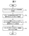
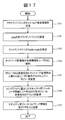
- FIG. 7 shows a processing procedure executed by the management server 106 that is notified of malware infection.
- the server processing unit 115 receives malware detection information from the client machine 103 (step 701).
- the malware detection information here is the malware detection information transmitted in step 602.
- the server processing unit 115 searches the policy database 109 based on the current time at which the policy is distributed, and distributes the security policy (at the time of policy application) for each combination of affiliation and post having the time 303 including the current time. Operation 304) is selected (step 702).
- a plurality of combinations can be selected.
- the server processing unit 115 compares the combination of affiliation and position that identifies the user for whom the security policy is selected with the combination of affiliation and position in the user database 107, and sends the transmission destination of the security policy distributed to each user. Is determined (step 703). Thereafter, the server processing unit 115 transmits the corresponding security policy and C & C server information to the determined IP address (step 704).
- the security policy and C & C server information here are the security policy and C & C server information received by the client machine in step 603.
- FIG. 8 shows the overall configuration of the information leakage prevention system 200 according to the present embodiment.
- the same or similar reference numerals are given to the corresponding parts to FIG.
- the basic configuration of the information leakage prevention system 200 is the same as the information leakage prevention system 100 of the first embodiment.
- Each of the client machines 803 and 811 has a computer as a basic configuration and includes a CPU, a RAM, a ROM, a hard disk device, a network interface, and the like.
- the anti-malware software 104 and the client processing unit 814 that are provided with functions through execution of programs by the CPU are installed in the client machines 803 and 811.
- a GPS terminal 805 is further mounted on the client machines 803 and 811 of this embodiment.
- the GPS terminal 805 may be externally attached to the client machine 803.
- the GPS terminal 805 acquires physical position information (latitude, longitude, altitude) of the client machines 803 and 811.
- the client processing unit 814 provides a user information transmission function, a position information processing function, a malware detection information transmission function, and a network control function through execution of a program by the CPU.
- a function different from the first embodiment is a position information processing function.
- the position information processing function acquires the current position information from the GPS terminal 805 in response to the request for position information, and transmits it to the request source (management server 806).
- the client processing unit 814 has a table for converting physical position information into management position information (for example, inside, outside, customer, employee's house, etc.), the management position information is transmitted as the position information. May be.
- the table used for conversion may be registered in advance in the client processing unit 814, or may be notified from the management server 806.
- the management server 806 has a computer as a basic configuration and includes a CPU, a RAM, a ROM, a hard disk device, a network interface, and the like. A display device is also connected to the management server 106 as necessary.
- a user database (database) 807, a security policy database (DB) 809, and a server processing unit 815 are installed.
- the server processing unit 815 provides a user information management function, a location information management function, a security policy management function, and a security policy transmission function through execution of a program by the CPU.
- a function different from the first embodiment is a position information management function.
- the location information management function requests the current location information from the client machines 803 and 811 when malware detection information is received.
- the position information management function registers the received position information in the user database 807.
- the position information management function converts the GPS information, which is physical position information, into management position information and registers it in the user database 807.
- a function for transmitting a table for converting GPS information to management position information to the client machines 803 and 811 may be implemented in the position information management function.
- the server processing unit 815 of the management server 806 when receiving the malware detection information, extracts the C & C server information from the malware detection information. Further, the server processing unit 815 searches the data 810 in the security policy database 809 based on the current time when the policy is distributed.
- the management server 806 selects a combination of security policy candidates and position information registered for a combination of affiliation and post related to the current time.
- the management server 806 collates the position information of the selected combination with the received position information, and determines the security policy that exercises the combination including the matching position information as the security policy to be applied to the corresponding user.
- the management server 806 extracts from the user database 807 an IP address corresponding to the determined combination of affiliation and position, and transmits a security policy and C & C server information corresponding to each user to the IP address.
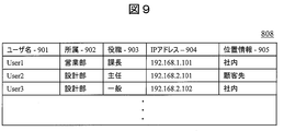
- FIG. 9 shows a structural example of the data 808 stored in the user database 807.
- the user database 807 includes, as data items, a user name 901, affiliation 902, title 903, client machine IP address 904, and location information 905 for each user.
- Information other than the position information 905 is transmitted from the client machines 803 and 811 to the management server 806 at the time of activation, and stored in the user database 807 by the management server 806.
- the management server 806 When the received user name 901 is already registered in the user database 807, the management server 806 newly receives information on the affiliation 902, post 903, and IP address 904 associated with the existing user name 901. Overwrite with. When the received user name 901 is not registered in the user database 807, the management server 806 stores the received user name 901, affiliation 902, title 903, and IP address 904 in a new row.
- the management server 806 When the management server 806 receives the location information 905 from the client machines 803 and 811, the management server 806 searches the user database 807 with the IP address 904 that is the transmission source of the location information 905, and the location received on the line where the IP address 904 matches. Information 905 is stored. In the case of the present embodiment, management position information is recorded in the position information 905.
- the IP address 904 that is the transmission source of the location information 905 is always stored in the user database 807. That is, the case where the IP address 904 that is the transmission source of the position information 905 is not stored in the user database 807 is not considered.
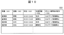
- FIG. 10 shows a structural example of the data 810 stored in the security policy database 809.
- the security policy database 809 has, as data items, affiliation 1001, title 1002, time 1003, location information 1004, and operation 1005 when applying the policy.
- management location information is recorded in the location information 1004.
- the management server 806 When the management server 806 receives malware detection information from any of the client machines 803 and 811, the management server 806 refers to the security policy database 809 and distributes the user's affiliation 1001, title 1002, and policy including the current time at which the policy is distributed.
- a security policy (operation 1005 when applying a policy) registered for the combination of the time 1003 and the position information 1004 is selected as a candidate. At this point in time, no security policy can be determined because no filtering is performed based on position information.
- the management server 806 When the combination of the time 1003 including the current time to distribute the policy, the affiliation 1001, the post 1002, and the location information 1004 is not registered in the security policy database 809, the management server 806 indicates that the operation 1005 when applying the policy is “network connection prohibited” And distribute the policy to all managed client machines.
- the administrator of the management server 806 can set an operation 1005 at the time of applying a policy for each combination of affiliation 1001, post 1002, time 1003, and position information 1004, and can change or delete data after the setting.
- FIG. 11 shows a processing procedure executed on the client machine 803 infected with malware. Malware infection is detected by anti-malware software 104 running on client machine 803. When detecting malware infection, the anti-malware software 104 outputs malware detection information (step 1101). Subsequently, the client processing unit 814 of the client machine 803 transmits malware detection information to the management server 806 (step 1102).
- the client processing unit 814 receives a position information acquisition request from the management server 806 (step 1103).
- the client processing unit 814 acquires position information from the GPS terminal 805, and transmits the acquired position information to the management server 806 (step 1104).
- the client processing unit 814 receives the security policy and C & C server information from the management server 806 (step 1105).
- the client processing unit 814 confirms whether the operation when applying the policy included in the received security policy is “network connection prohibited” or “C & C server connection prohibited” (step 1106).
- the client processing unit 814 disconnects the connection to the network 102 and isolates itself from the network (step 1107).
- the client processing unit 814 prohibits connection only to the address of the C & C server 101 included in the received C & C server information (step 1108). . Note that the operations after step 1103 are executed on the client machine 811 that is not infected with malware.
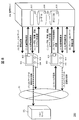
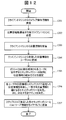
- FIG. 12 shows a processing procedure executed by the management server 806 notified of malware infection.
- the server processing unit 815 receives malware detection information from the client machine 803 (step 1201).
- the malware detection information here is the malware detection information transmitted in step 1102.
- the server processing unit 815 transmits a position information acquisition request to the client machines 803 and 811 (step 1202).
- the server processing unit 815 transmits a position information acquisition request not only to the client machine 803 that has detected the infection of malware, but also to all client machines under management.
- the server processing unit 815 receives position information from the client machines 803 and 811 (step 1203).
- the position information here is the position information transmitted in step 1104.
- the server processing unit 815 stores the received position information in the user database 807 (step 1204).
- the server processing unit 815 searches the policy database 809 based on the current time when the policy is distributed, and the security policy registered for the user having the time 1003 including the current time (operation 1005 when applying the policy). And position information 1004 are selected (step 1205).
- the server processing unit 815 compares the user location information 1004 corresponding to the security policy selected in Step 1205 with the location information 905 registered in the user database 807 (ie, the time 1003 and the matching user). The attribute and security policy of the user who satisfies both conditions of the position information 1004 are specified. Further, the server processing unit 815 determines the IP address of the user corresponding to the specified attribute and position information 905 from the user database 807 (step 1206).
- the server processing unit 815 transmits the corresponding security policy and C & C server information to the determined IP address (step 1207).
- the security policy and C & C server information here are the security policy and C & C server information received by the client machine in step 1105.
- Example 3 (3-1) System Configuration
- a security policy is determined in consideration of the number of network managers present, and a system for preventing information leakage by controlling network connection of a client machine and access to a C & C server. explain about.
- the network administrator is, for example, all staff belonging to the system department and manager staff of each department.
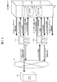
- FIG. 13 shows the overall configuration of the information leakage prevention system 300 according to the present embodiment.
- the same or similar reference numerals are given to the corresponding parts to FIG.
- the basic configuration of the information leakage prevention system 300 is the same as that of the information leakage prevention system 100 of the first embodiment.
- Each of the client machines 1303 and 1311 has a computer as a basic configuration and includes a CPU, a RAM, a ROM, a hard disk device, a network interface, and the like.
- the anti-malware software 104 and the client processing unit 1314 that are provided with functions through execution of programs by the CPU are installed in the client machines 1303 and 1311.
- the client processing unit 1314 provides a user information transmission function, a presence information processing function, a malware detection information transmission function, and a network control function through execution of a program by the CPU.
- a function different from the first embodiment is a seated information processing function.
- the presence information processing function provides a function of transmitting a response (echo reply) to the management server 1306 when the PC is activated when a presence information transmission request (ping) is received from the management server 1306.
- the management server 1306 has a computer as a basic configuration and includes a CPU, a RAM, a ROM, a hard disk device, a network interface, and the like. A display device is also connected to the management server 1306 as necessary.
- a user database (database) 1307, a security policy database (database) 1309, and a server processing unit 1315 are installed.
- the server processing unit 1315 provides a user information management function, a presence information management function, a security policy management function, and a security policy transmission function through execution of a program by the CPU.
- a function different from the first embodiment is a presence information management function.
- the presence information management function provides a function of transmitting a ping to all client machines 1303 and 1311 under management when malware detection information is received.
- the presence information management function receives a reply to ping (echo ⁇ reply)
- the presence information management function determines whether the user of the transmission source client machines 1303 and 1311 is a network administrator.
- a function of registering seat information in the user database 1307 is provided.
- the security policy transmission function of this embodiment receives C & C server information from the received malware detection information when a response (echo reply) is received from all the client machines 1303 and 1311 that transmitted the ping, or when a timeout occurs.
- the number of network managers who are present is counted from the data 1308 that is extracted and stored in the user database 1307.
- the security policy transmission function of this embodiment is based on the current time when the policy is distributed and the calculated number of network managers. Is selected from the security policy database 1309. Further, the security policy transmission function of the present embodiment extracts the IP address corresponding to the combination of affiliation and job title corresponding to the selected security policy from the user database 1307, and the security policy and C & C previously selected for the IP address. Send server information.
- FIG. 14 shows a structural example of the data 1308 stored in the user database 1307.
- the user database 1307 includes, as data items, a user name 1401, affiliation 1402, job title 1403, client machine IP address 1404, and presence information 1405 for each user.
- Information other than presence information 1405 is transmitted from the client machines 1303 and 1311 to the management server 1306 at the time of activation, and stored in the user database 1307 by the management server 1306.
- the management server 1306 When the received user name 1401 is already registered in the user database 1307, the management server 1306 displays the affiliation 1402 and the post 140 associated with the existing user name 1401. 3 and IP address 1404 are overwritten with the newly received information. When the received user name 1401 is not registered in the user database 1307, the management server 1306 stores the received user name 1401, affiliation 1402, title 1403, and IP address 1404 in a new row.
- the management server 1306 When the management server 1306 receives echo reply in response to the ping transmission, the management server 1306 searches the user database 1307 using the IP address 1404 that is the ping transmission destination, and the job title 1403 of the user whose IP address 1404 matches is the section manager. If so, “present” is stored in the presence information 1405. This function is executed by the presence information management function.
- the IP address 1404 that is the ping destination is always stored in the user database 1307. This is not considered when the IP address 1404 that is the transmission destination is not stored in the user database 1307.
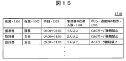
- FIG. 15 shows an example of the structure of data 1310 stored in the security policy database 1309.
- the security policy database 1308 includes, as data items, an affiliation 1501, a job title 1502, a policy distribution time 1503, a network administrator attendance 1504 necessary for applying the policy, and an operation 1505 when the policy is applied.
- the management server 1306 When the management server 1306 receives malware detection information from any of the client machines 1303 and 1310 and then receives echo reply from all of the ping destinations, or when a timeout occurs, the management server 1306 is present from the user database 1307 Count the number of network administrators inside. Further, the management server 1306 refers to the security policy database 1309 based on the number of network managers counted from the user database 1307 and the current time at which the policy is distributed, and the user's affiliation 1501, job title 1502, A security policy to be applied (operation 1505 when the policy is applied) is selected.
- the management server 1306 treats the operation 1505 when applying the policy as “network connection prohibited”, and distributes the policy to all client machines under management.
- the administrator of the management server 1306 can set an operation 1505 when applying a policy for each combination of affiliation 1501, title 1502, time 1503, and number of attendees 1504 of the administrator. Can be changed or deleted.
- FIG. 16 shows a processing procedure executed on the client machine 1303 infected with malware. Infection with malware is detected by the anti-malware software 104 running on the client machine 1303. When detecting malware infection, the anti-malware software 104 outputs malware detection information (step 1601). Subsequently, the client processing unit 1314 of the client machine 1303 transmits malware detection information to the management server 1306 (step 1602).
- the client processing unit 1314 receives a ping from the management server 1306 (step 1603).
- the client processing unit 1314 transmits echo reply to the management server 1306 (step 1604).
- the client processing unit 1314 receives the security policy and C & C server information from the management server 1306 (step 1605).
- the client processing unit 1314 confirms whether the operation at the time of applying the policy included in the received security policy is “network connection prohibited” or “C & C server connection prohibited” (step 1606).
- the client processing unit 1314 disconnects the connection to the network 102 and isolates itself from the network (step 1607).
- the client processing unit 1314 prohibits connection only to the address of the C & C server 101 included in the received C & C server information (step 1608). .
- the client machine 1311 that is not infected with malware executes the operations after Step 1603.
- FIG. 17 shows a processing procedure executed by the management server 1306 notified of malware infection.
- the server processing unit 1315 receives malware detection information from the client machine 1303 (step 1701).
- the malware detection information here is the malware detection information transmitted in step 1602.
- the server processing unit 1315 transmits a ping to the client machines 1303 and 1311 (step 1702). That is, the server processing unit 1315 transmits a position information acquisition request not only to the client machine 1303 that has detected the malware infection but also to all client machines under management. Thereafter, the server processing unit 1315 receives echoereply from the client machines 1303 and 1311 (step 1703).
- the echo reply here is the echo reply sent in step 1604. However, echo reply cannot be received from all of the client machines 1303 and 1311.
- the server processing unit 1315 stores the presence information of the user who uses the client machine that transmitted echo ⁇ ⁇ ⁇ ⁇ ⁇ ⁇ reply in the user database 1307 (step 1704). However, the server processing unit 1315 registers only the presence information of the network administrator in the user database 1307, and other users do not register the presence information.
- the server processing unit 1315 selects a security policy to be distributed based on a user who satisfies the combination of the current time at which the policy is distributed and the number of network administrators who are present (step 1705).
- the server processing unit 1315 compares the user information (affiliation and title) of the user corresponding to the security policy selected in step 1705 with the user information (affiliation and title) in the user database 1307, and becomes the transmission destination of each security policy.
- An IP address is determined (step 1706).
- the server processing unit 1315 transmits the corresponding security policy and C & C server information to the determined IP address (step 1707).
- the security policy and C & C server information here are the security policy and C & C server information received by the client machine in step 1605.
- the present disclosure is not limited to the above-described embodiments, and includes various modifications.
- the above-described embodiments have been described in detail for easy understanding of the present disclosure, and it is not always necessary to include all the configurations described.
- a part of one embodiment can be replaced with the configuration of another embodiment.
- the structure of another Example can also be added to the structure of a certain Example.
- a part of the configuration of another embodiment can be added, deleted, or replaced.
- each of the above-described configurations, functions, processing units, processing means, and the like may be realized by hardware by designing a part or all of them with, for example, an integrated circuit.
- Each of the above-described configurations, functions, and the like may be realized by the processor interpreting and executing a program that realizes each function (that is, in software).
- Information such as programs, tables, and files that realize each function can be stored in a storage device such as a memory, a hard disk, or an SSD (Solid State Drive), or a storage medium such as an IC card, an SD card, or a DVD.
- Control lines and information lines indicate what is considered necessary for the description, and do not represent all control lines and information lines necessary for the product. In practice, it can be considered that almost all components are connected to each other.
- 100 Information leakage prevention system, 101 ... C & C server 101 102 ... Network, 103, 111 ... client machine, 104 ... Anti-malware software, 106 ... management server, 107 ... user database, 109 ... security policy database, 114: Client processing unit, 115 ... Server processing unit, 200 ... Information leakage prevention system, 803, 211 ... client machine, 806 ... management server, 807 ... user database, 809 ... security policy database, 814 ... Client processing unit, 815 ... Server processing unit, 300 ... Information leakage prevention system, 1303, 1311 ... client machine, 1306: Management server, 1307: User database, 1309: Security policy database, 1314: Client processing unit, 1315: Server processing unit.
Landscapes
- Engineering & Computer Science (AREA)
- Computer Security & Cryptography (AREA)
- General Engineering & Computer Science (AREA)
- Computer Hardware Design (AREA)
- Signal Processing (AREA)
- Computer Networks & Wireless Communication (AREA)
- Computing Systems (AREA)
- Theoretical Computer Science (AREA)
- Software Systems (AREA)
- General Physics & Mathematics (AREA)
- Physics & Mathematics (AREA)
- Health & Medical Sciences (AREA)
- General Health & Medical Sciences (AREA)
- Bioethics (AREA)
- Data Exchanges In Wide-Area Networks (AREA)
- Computer And Data Communications (AREA)
- Virology (AREA)
Abstract
L'invention concerne une technologie de prévention de fuites d'informations qui ne nécessite pas d'appareil dédié pour administrer l'accès sur un réseau, et qui présente une excellente flexibilité en termes de politique de sécurité. Le système de prévention de fuites d'informations comprend un terminal client qui comporte une unité de traitement de client qui effectue une commande de réseau en fonction d'une politique de sécurité acquise, et un serveur administratif comportant : une base de données d'utilisateurs qui stocke des informations à propos d'utilisateurs utilisant le terminal client; une base de données de politiques de sécurité qui stocke des politiques de sécurité permettant de déterminer le contenu de commande de réseau pour chaque attribut d'utilisateur; et une unité de traitement de serveur qui sélectionne une politique de sécurité en fonction d'un attribut d'utilisateur et du moment auquel la politique de sécurité est distribuée, et qui transmet la politique de sécurité sélectionnée à un terminal client correspondant.
Priority Applications (1)
| Application Number | Priority Date | Filing Date | Title |
|---|---|---|---|
| US15/753,249 US10924492B2 (en) | 2015-12-25 | 2016-11-25 | Information leakage prevention system and method |
Applications Claiming Priority (2)
| Application Number | Priority Date | Filing Date | Title |
|---|---|---|---|
| JP2015-254597 | 2015-12-25 | ||
| JP2015254597A JP6340358B2 (ja) | 2015-12-25 | 2015-12-25 | 情報漏洩防止システム及び方法 |
Publications (1)
| Publication Number | Publication Date |
|---|---|
| WO2017110363A1 true WO2017110363A1 (fr) | 2017-06-29 |
Family
ID=59089329
Family Applications (1)
| Application Number | Title | Priority Date | Filing Date |
|---|---|---|---|
| PCT/JP2016/085003 WO2017110363A1 (fr) | 2015-12-25 | 2016-11-25 | Système et procédé de prévention de fuites d'informations |
Country Status (3)
| Country | Link |
|---|---|
| US (1) | US10924492B2 (fr) |
| JP (1) | JP6340358B2 (fr) |
| WO (1) | WO2017110363A1 (fr) |
Cited By (1)
| Publication number | Priority date | Publication date | Assignee | Title |
|---|---|---|---|---|
| JPWO2019064458A1 (ja) * | 2017-09-28 | 2020-07-02 | 株式会社オプティム | コンピュータシステム、セキュリティ設定提案方法及びプログラム |
Families Citing this family (4)
| Publication number | Priority date | Publication date | Assignee | Title |
|---|---|---|---|---|
| JP7009955B2 (ja) * | 2017-11-24 | 2022-01-26 | トヨタ自動車株式会社 | 医療データ通信装置、サーバ、医療データ通信方法および医療データ通信プログラム |
| JP7013817B2 (ja) * | 2017-11-24 | 2022-02-01 | トヨタ自動車株式会社 | 医療情報システム、医療装置、データ通信方法、及び、プログラム |
| JP7198617B2 (ja) * | 2018-09-21 | 2023-01-04 | 株式会社日立ハイテクソリューションズ | セキュリティシステム |
| CN110381088B (zh) * | 2019-08-21 | 2021-11-12 | 牡丹江师范学院 | 一种基于物联网的数据安全保障方法 |
Citations (6)
| Publication number | Priority date | Publication date | Assignee | Title |
|---|---|---|---|---|
| JP2008165601A (ja) * | 2006-12-28 | 2008-07-17 | Secure Ware:Kk | 通信監視システム、通信監視装置、及び通信制御装置 |
| JP2008288686A (ja) * | 2007-05-15 | 2008-11-27 | Fuji Xerox Co Ltd | 画像読取装置、画像処理システム及び画像処理プログラム |
| JP2009070073A (ja) * | 2007-09-12 | 2009-04-02 | Sumitomo Electric Ind Ltd | 情報処理装置及びエージェントコンピュータプログラム |
| JP2009169719A (ja) * | 2008-01-17 | 2009-07-30 | Fuji Xerox Co Ltd | セキュリティポリシーサーバ、セキュリティポリシー管理システム及びセキュリティポリシー管理プログラム |
| JP2010068427A (ja) * | 2008-09-12 | 2010-03-25 | Oki Electric Ind Co Ltd | 情報制御システム、情報制御方法、および、移動中継装置 |
| JP2011100362A (ja) * | 2009-11-06 | 2011-05-19 | Nippon Telegr & Teleph Corp <Ntt> | 情報アクセス制御システムとそのサーバ装置及び情報アクセス制御方法 |
Family Cites Families (12)
| Publication number | Priority date | Publication date | Assignee | Title |
|---|---|---|---|---|
| US20020116639A1 (en) * | 2001-02-21 | 2002-08-22 | International Business Machines Corporation | Method and apparatus for providing a business service for the detection, notification, and elimination of computer viruses |
| US7069316B1 (en) * | 2002-02-19 | 2006-06-27 | Mcafee, Inc. | Automated Internet Relay Chat malware monitoring and interception |
| US8566946B1 (en) * | 2006-04-20 | 2013-10-22 | Fireeye, Inc. | Malware containment on connection |
| US9705911B2 (en) * | 2005-06-30 | 2017-07-11 | Nokia Technologies Oy | System and method for using quarantine networks to protect cellular networks from viruses and worms |
| US8381298B2 (en) * | 2008-06-30 | 2013-02-19 | Microsoft Corporation | Malware detention for suspected malware |
| JP5518594B2 (ja) | 2010-06-30 | 2014-06-11 | 三菱電機株式会社 | 内部ネットワーク管理システム及び内部ネットワーク管理方法及びプログラム |
| GB201306628D0 (en) * | 2013-04-11 | 2013-05-29 | F Secure Oyj | Detecting and marking client devices |
| US9294486B1 (en) * | 2014-03-05 | 2016-03-22 | Sandia Corporation | Malware detection and analysis |
| TWI528216B (zh) * | 2014-04-30 | 2016-04-01 | 財團法人資訊工業策進會 | 隨選檢測惡意程式之方法、電子裝置、及使用者介面 |
| US9621563B2 (en) * | 2015-03-27 | 2017-04-11 | International Business Machines Corporation | Geographical location authentication |
| US9858424B1 (en) * | 2017-01-05 | 2018-01-02 | Votiro Cybersec Ltd. | System and method for protecting systems from active content |
| US10963566B2 (en) * | 2018-01-25 | 2021-03-30 | Microsoft Technology Licensing, Llc | Malware sequence detection |
-
2015
- 2015-12-25 JP JP2015254597A patent/JP6340358B2/ja active Active
-
2016
- 2016-11-25 WO PCT/JP2016/085003 patent/WO2017110363A1/fr active Application Filing
- 2016-11-25 US US15/753,249 patent/US10924492B2/en active Active
Patent Citations (6)
| Publication number | Priority date | Publication date | Assignee | Title |
|---|---|---|---|---|
| JP2008165601A (ja) * | 2006-12-28 | 2008-07-17 | Secure Ware:Kk | 通信監視システム、通信監視装置、及び通信制御装置 |
| JP2008288686A (ja) * | 2007-05-15 | 2008-11-27 | Fuji Xerox Co Ltd | 画像読取装置、画像処理システム及び画像処理プログラム |
| JP2009070073A (ja) * | 2007-09-12 | 2009-04-02 | Sumitomo Electric Ind Ltd | 情報処理装置及びエージェントコンピュータプログラム |
| JP2009169719A (ja) * | 2008-01-17 | 2009-07-30 | Fuji Xerox Co Ltd | セキュリティポリシーサーバ、セキュリティポリシー管理システム及びセキュリティポリシー管理プログラム |
| JP2010068427A (ja) * | 2008-09-12 | 2010-03-25 | Oki Electric Ind Co Ltd | 情報制御システム、情報制御方法、および、移動中継装置 |
| JP2011100362A (ja) * | 2009-11-06 | 2011-05-19 | Nippon Telegr & Teleph Corp <Ntt> | 情報アクセス制御システムとそのサーバ装置及び情報アクセス制御方法 |
Cited By (1)
| Publication number | Priority date | Publication date | Assignee | Title |
|---|---|---|---|---|
| JPWO2019064458A1 (ja) * | 2017-09-28 | 2020-07-02 | 株式会社オプティム | コンピュータシステム、セキュリティ設定提案方法及びプログラム |
Also Published As
| Publication number | Publication date |
|---|---|
| JP6340358B2 (ja) | 2018-06-06 |
| US20180241758A1 (en) | 2018-08-23 |
| JP2017117354A (ja) | 2017-06-29 |
| US10924492B2 (en) | 2021-02-16 |
Similar Documents
| Publication | Publication Date | Title |
|---|---|---|
| US11575703B2 (en) | Network security threat intelligence sharing | |
| WO2017110363A1 (fr) | Système et procédé de prévention de fuites d'informations | |
| US10958690B1 (en) | Security appliance to monitor networked computing environment | |
| US11647043B2 (en) | Identifying security actions based on computing asset relationship data | |
| US7592906B1 (en) | Network policy evaluation | |
| US11153184B2 (en) | Technologies for annotating process and user information for network flows | |
| EP3373179B1 (fr) | Dispositif, procédé et programme de traitement d'informations | |
| US9667643B2 (en) | Apparatus, system, and method for correlating security vulnerabilities from multiple independent vulnerability assessment methods | |
| US10242185B1 (en) | Dynamic guest image creation and rollback | |
| US8739287B1 (en) | Determining a security status of potentially malicious files | |
| EP2744251A1 (fr) | Système de réseau, dispositif de communication mobile et programme | |
| US9948649B1 (en) | Internet address filtering based on a local database | |
| CN108768926A (zh) | 受感染主机设备的跟踪和缓解 | |
| US10003601B1 (en) | Security management application providing proxy for administrative privileges | |
| US11159570B2 (en) | Cloud native discovery and protection | |
| US20100115587A1 (en) | Authentication system and terminal authentication apparatus | |
| CN108933773A (zh) | 在完成文件的接收之前使用元数据标识文件并确定文件的安全性分类 | |
| US20220217148A1 (en) | Techniques for protecting cloud native environments based on cloud resource access | |
| EP3750289B1 (fr) | Procédé, appareil, et support lisible par ordinateur pour fournir un service de sécurité à un centre de données | |
| US20080172742A1 (en) | Information processing system | |
| US20210117536A1 (en) | Information processing device and information processing method | |
| CN102761535A (zh) | 病毒监测方法和设备 | |
| US8856330B2 (en) | System for determining whether to block internet access of a portable system based on its current network configuration | |
| KR101911913B1 (ko) | 서비스 기능 체이닝 방법 및 이를 위한 장치 | |
| KR101733770B1 (ko) | 가상랜을 이용하여 사내 단말의 보안을 관리하는 사내 보안 관리 장치, 사내 보안 관리 시스템 및 사내 보안 관리 방법 |
Legal Events
| Date | Code | Title | Description |
|---|---|---|---|
| 121 | Ep: the epo has been informed by wipo that ep was designated in this application |
Ref document number: 16878257 Country of ref document: EP Kind code of ref document: A1 |
|
| WWE | Wipo information: entry into national phase |
Ref document number: 15753249 Country of ref document: US |
|
| NENP | Non-entry into the national phase |
Ref country code: DE |
|
| 122 | Ep: pct application non-entry in european phase |
Ref document number: 16878257 Country of ref document: EP Kind code of ref document: A1 |