WO2017110363A1 - Information leakage prevention system and method - Google Patents
Information leakage prevention system and method Download PDFInfo
- Publication number
- WO2017110363A1 WO2017110363A1 PCT/JP2016/085003 JP2016085003W WO2017110363A1 WO 2017110363 A1 WO2017110363 A1 WO 2017110363A1 JP 2016085003 W JP2016085003 W JP 2016085003W WO 2017110363 A1 WO2017110363 A1 WO 2017110363A1
- Authority
- WO
- WIPO (PCT)
- Prior art keywords
- information
- security policy
- user
- server
- client terminal
- Prior art date
Links
Images


Classifications
-
- H—ELECTRICITY
- H04—ELECTRIC COMMUNICATION TECHNIQUE
- H04L—TRANSMISSION OF DIGITAL INFORMATION, e.g. TELEGRAPHIC COMMUNICATION
- H04L63/00—Network architectures or network communication protocols for network security
- H04L63/10—Network architectures or network communication protocols for network security for controlling access to devices or network resources
- H04L63/105—Multiple levels of security
-
- G—PHYSICS
- G06—COMPUTING; CALCULATING OR COUNTING
- G06F—ELECTRIC DIGITAL DATA PROCESSING
- G06F21/00—Security arrangements for protecting computers, components thereof, programs or data against unauthorised activity
- G06F21/50—Monitoring users, programs or devices to maintain the integrity of platforms, e.g. of processors, firmware or operating systems
- G06F21/55—Detecting local intrusion or implementing counter-measures
- G06F21/554—Detecting local intrusion or implementing counter-measures involving event detection and direct action
-
- G—PHYSICS
- G06—COMPUTING; CALCULATING OR COUNTING
- G06F—ELECTRIC DIGITAL DATA PROCESSING
- G06F21/00—Security arrangements for protecting computers, components thereof, programs or data against unauthorised activity
- G06F21/60—Protecting data
-
- H—ELECTRICITY
- H04—ELECTRIC COMMUNICATION TECHNIQUE
- H04L—TRANSMISSION OF DIGITAL INFORMATION, e.g. TELEGRAPHIC COMMUNICATION
- H04L41/00—Arrangements for maintenance, administration or management of data switching networks, e.g. of packet switching networks
- H04L41/08—Configuration management of networks or network elements
- H04L41/0893—Assignment of logical groups to network elements
-
- H—ELECTRICITY
- H04—ELECTRIC COMMUNICATION TECHNIQUE
- H04L—TRANSMISSION OF DIGITAL INFORMATION, e.g. TELEGRAPHIC COMMUNICATION
- H04L41/00—Arrangements for maintenance, administration or management of data switching networks, e.g. of packet switching networks
- H04L41/28—Restricting access to network management systems or functions, e.g. using authorisation function to access network configuration
-
- H—ELECTRICITY
- H04—ELECTRIC COMMUNICATION TECHNIQUE
- H04L—TRANSMISSION OF DIGITAL INFORMATION, e.g. TELEGRAPHIC COMMUNICATION
- H04L63/00—Network architectures or network communication protocols for network security
- H04L63/10—Network architectures or network communication protocols for network security for controlling access to devices or network resources
- H04L63/102—Entity profiles
-
- H—ELECTRICITY
- H04—ELECTRIC COMMUNICATION TECHNIQUE
- H04L—TRANSMISSION OF DIGITAL INFORMATION, e.g. TELEGRAPHIC COMMUNICATION
- H04L63/00—Network architectures or network communication protocols for network security
- H04L63/14—Network architectures or network communication protocols for network security for detecting or protecting against malicious traffic
- H04L63/1408—Network architectures or network communication protocols for network security for detecting or protecting against malicious traffic by monitoring network traffic
- H04L63/1416—Event detection, e.g. attack signature detection
-
- H—ELECTRICITY
- H04—ELECTRIC COMMUNICATION TECHNIQUE
- H04L—TRANSMISSION OF DIGITAL INFORMATION, e.g. TELEGRAPHIC COMMUNICATION
- H04L63/00—Network architectures or network communication protocols for network security
- H04L63/20—Network architectures or network communication protocols for network security for managing network security; network security policies in general
-
- G—PHYSICS
- G06—COMPUTING; CALCULATING OR COUNTING
- G06F—ELECTRIC DIGITAL DATA PROCESSING
- G06F21/00—Security arrangements for protecting computers, components thereof, programs or data against unauthorised activity
- G06F21/50—Monitoring users, programs or devices to maintain the integrity of platforms, e.g. of processors, firmware or operating systems
- G06F21/55—Detecting local intrusion or implementing counter-measures
- G06F21/56—Computer malware detection or handling, e.g. anti-virus arrangements
Definitions
- This disclosure relates to information leakage prevention technology for preventing information leakage due to malware, for example.
- Patent Literature As a technique for preventing damage by blocking the connection from an infected client machine to the C & C server or isolating the infected client machine from the network when malware infection is detected by anti-malware software, for example, Patent Literature There is a technique described in 1.
- Japanese Patent Application Laid-Open No. 2004-151561 describes a technique for blocking a packet destined for a specific address using a firewall device and a relay device when a traffic abnormality is detected.
- Patent Document 1 the technique described in Patent Document 1 is based on the assumption that a firewall device and a relay device exist between an external network and a client machine, and the client machine is installed in a specific internal network where the firewall device and the relay device exist. There is a need to. For this reason, information leakage from client machines located outside the internal network cannot be prevented.
- Patent Document 1 uses a firewall device and a relay device to uniformly limit access to the outside. For this reason, only the same level of countermeasures can be taken for all client machines existing in the internal network. In addition, it is impossible to flexibly cope with such a case that the security strength is changed by a user who uses each client machine, a network connection is permitted within a range that is recognized as safe, and the use restriction of the user is reduced.
- the present disclosure employs, for example, the configuration described in the claims.
- the present specification includes a plurality of means for solving the above-described problems.
- a client terminal having a client processing unit that performs network control in accordance with an acquired security policy and the client terminal are used.
- a user database for storing information about the user to perform
- a security policy database for storing a security policy that defines network control content for each user attribute, and the security policy based on the user attribute and the time at which the security policy is distributed.
- An information leakage prevention system comprising: a management server having a server processing unit that selects and transmits the selected security policy to the corresponding client terminal.
- the present disclosure it is possible to block information transmission from the client terminal to the C & C server or to isolate the client terminal from the network even in a network where there is no firewall device or relay device. Moreover, according to this indication, the strength of a security policy can be changed according to the attribute of the user of a client terminal. Problems, configurations, and effects other than those described above will become apparent from the following description of embodiments.
- FIG. 1 is a diagram illustrating an overall configuration of a system according to Embodiment 1.
- FIG. The figure explaining the structure of the data stored in the user database (Example 1).
- FIG. 4 is a diagram for explaining the structure of data stored in a security policy database (Example 1).
- 10 is a flowchart for explaining a processing procedure when starting a client machine (first embodiment).
- 10 is a flowchart for explaining a processing procedure of the management server when the client machine is activated (first embodiment).
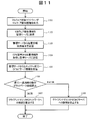
- the flowchart explaining the process sequence of the client machine at the time of malware infection Example 1).
- the flowchart explaining the process sequence of the management server at the time of malware infection Example 1).
- FIG. 3 is a diagram illustrating an overall configuration of a system according to a second embodiment.
- FIG. 6 is a diagram for explaining the structure of data stored in a security policy database (second embodiment).
- the flowchart explaining the processing procedure of the client machine at the time of malware infection (Example 2).
- the flowchart explaining the process sequence of the management server at the time of malware infection (Example 2).
- FIG. 10 is a diagram illustrating an overall configuration of a system according to a third embodiment.
- FIG. 10 is a diagram for explaining the structure of data stored in a security policy database (third embodiment).
- a flowchart explaining the processing procedure of the client machine at the time of malware infection (Example 3).
- the flowchart explaining the process sequence of the management server at the time of malware infection (Example 3).
- FIG. 1 shows an overall configuration of an information leakage prevention system 100 according to the present embodiment.
- the information leakage prevention system 100 is a system that controls the client machine's network connection and access to the C & C server by cooperation between the client machine and the management server, and prevents information leakage due to malware infection.
- the information leakage prevention system 100 includes a management server 106 and client machines 103 and 111.
- the management server 106 and the client machines 103 and 111 are connected through the network 102.
- FIG. 1 only the client machines 103 and 111 are shown, but the number of client machines is arbitrary.
- Each of the client machines 103 and 111 has a computer as a basic configuration and includes a CPU, a RAM, a ROM, a hard disk device, a network interface, a display device, and the like.
- the anti-malware software 104 and the client processing unit 114 that are provided with functions through execution of programs by the CPU are installed in the client machines 103 and 111.
- the anti-malware software 104 is a program that detects malware infection.
- the client processing unit 114 includes a user information transmission function, a malware detection information transmission function, and a network control function.
- the user information transmission function is used for transmitting user information
- the malware detection information transmission function is used for transmission of malware detection information
- the network control function controls connection or disconnection with a network or the like.
- the management server 106 has a computer as a basic configuration and includes a CPU, a RAM, a ROM, a hard disk device, a network interface, and the like. A display device is also connected to the management server 106 as necessary.
- the management server 106 according to the present embodiment includes a user database (database) 107, a security policy database (DB) 109, and a server processing unit 115.
- the server processing unit 115 provides a user information management function, a security policy management function, and a security policy transmission function through execution of a program by the CPU.
- the user information management function manages the user database 107
- the security policy management function manages the security policy database 109
- the security policy transmission function is used for transmission of the security policy.
- the user database 107 stores data 108 such as the user name (or identifier), affiliation, title, and IP address of the client machine of each user. In this specification, these pieces of information are collectively referred to as “information about the user”. Also, the user name (or identifier), affiliation, and title of each user are collectively referred to as “user information”. In this embodiment, the affiliation, title, and policy distribution time of each user are also collectively referred to as “attributes”.
- the security policy database 109 stores data 110 describing affiliation, title, policy distribution time, policy application operation, and the like.
- the client machines 103 and 111 activated by the user transmit user information (user name, affiliation, title) registered in advance and the IP address (at the time of activation) of the own machine to the management server 106.
- user information user name, affiliation, title
- IP address at the time of activation
- the client machines 103 and 111 indicate the changed user name, affiliation, title, and IP address (after update) to the management server 106.
- the management server 106 receives information on the user name, affiliation, title, and IP address of each user from the client machines 103 and 111, the management server 106 stores them in the user database 107.
- the client machine 103 when the client machine 103 is infected with malware, the client machine 103 transmits malware detection information output from the anti-malware software 104 to the management server 106.
- the malware detection information includes detection date and time and C & C server information that is a communication destination of the malware.
- the management server 106 When the management server 106 receives malware detection information, the management server 106 extracts C & C server information from the detection information. Next, the management server 106 specifies the current time at which the policy is distributed, and searches the data 110 stored in the security policy database 109 at the specified current time. Here, the management server 106 selects a security policy registered for a combination of affiliation and post related to the current time. In addition, the management server 106 extracts each IP address corresponding to the combination of affiliation and title related to the current time from the data 108 stored in the user database 107, and sends each IP address to the IP address. A security policy and C & C server information corresponding to is transmitted. The transmission destination here is not limited to the client machine 103 infected with malware. In the case of FIG. 1, both of the client machines 103 and 111 are transmission destinations of the security policy and C & C server information.
- the client machines 103 and 111 that have received the security policy and the C & C server information disconnect the connection with the C & C server 101 or the network 102 according to the content of the received security policy.
- the client machine 103 disconnects the connection with the network 102
- the client machine 111 disconnects only the connection with the C & C server 101 (maintains the connection with the network).
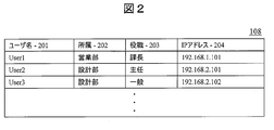
- FIG. 2 shows a structural example of the data 108 stored in the user database 107.
- the user database 107 includes, as data items, a user name 201, an affiliation 202, a job title 203, and an IP address 204 of the client machine for each user. These pieces of information are transmitted from the client machines 103 and 111 to the management server 106 at the time of activation, and are stored in corresponding item positions by the management server 106.
- the management server 106 When the received user name 201 is already registered in the user database 107, the management server 106 newly receives information on the affiliation 202, post 203, and IP address 204 associated with the existing user name 201. Overwrite with. When the received user name 201 is not registered in the user database 107, the management server 106 stores the received user name 201, affiliation 202, title 203, and IP address 204 in a new line. The administrator of the management server 106 can delete unnecessary rows from the user database 107.
- FIG. 3 shows an example of the structure of the data 110 stored in the security policy database 109.
- the security policy database 109 has, as data items, an affiliation 301, a post 302, a policy distribution time 303, and a policy application operation 304.
- the management server 106 searches the security policy database 109 at the current time for distributing the policy, and includes the user (affiliation 301) included in the time 303 including the current time. And a security policy (operation 304 at the time of policy application) to be applied is selected.
- the management server 106 When the combination of the affiliation 301 and the post 302 associated with the time 303 including the current time at which the policy is distributed is not registered in the security policy database 109, the management server 106 indicates that the operation 304 at the time of applying the policy is “prohibit network connection”. And distribute the policy to all managed client machines. “Prohibit network connection” is the most severe operation. The administrator of the management server 106 can set the operation 304 when applying the policy for each combination of the affiliation 301, the post 302, and the time 303, and can change or delete the data even after the setting.
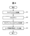
- FIG. 4 shows a processing procedure executed by the client machines 103 and 111 when the client machine is started.
- the client processing unit 114 logs in to an OS (Operation System) (step 402).
- the client processing unit 114 acquires its own IP address (step 403).
- the client processing unit 114 transmits the own IP address acquired in step 403 and user information (user name, affiliation, job title information) registered in advance to the management server 106 (step 404). ).
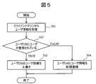
- FIG. 5 shows a processing procedure executed by the management server 106 when the client machine is activated.
- the server processing unit 115 of the management server 106 receives the IP address and user information from the client machines 103 and 111 (step 501).
- the user information here is the user information transmitted in step 404.
- the server processing unit 115 checks whether or not the user name included in the received user information is registered in the user database 107 (step 502).
- the server processing unit 115 overwrites each information of the affiliation 202, post 203, and IP address 204 associated with the user name with the contents of the received user information. Update (step 503).
- the server processing unit 115 newly registers the content of the received user information in the user database 107 (step 504).
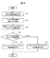
- FIG. 6 shows a processing procedure executed on the client machine 103 infected with malware. Malware infection is detected by the anti-malware software 104 running on the client machine 103. When detecting malware infection, the anti-malware software 104 outputs malware detection information (step 601). Subsequently, the client processing unit 114 of the client machine 103 transmits malware detection information to the management server 106 (step 602).
- the client processing unit 114 receives the security policy and C & C server information from the management server 106 (step 603).
- the client processing unit 114 confirms whether the operation at the time of applying the policy included in the received security policy is “network connection prohibited” or “C & C server connection prohibited” (step 604). If the operation at the time of applying the policy is “network connection prohibited”, the client processing unit 114 disconnects the connection to the network 102 and isolates itself from the network (step 605). On the other hand, when the operation at the time of applying the policy is “C & C server connection prohibited”, the client processing unit 114 prohibits connection only to the address of the C & C server 101 included in the received C & C server information (step 606). . Note that the operation after step 603 is executed in the client machine 111 that is not infected with malware.
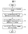
- FIG. 7 shows a processing procedure executed by the management server 106 that is notified of malware infection.
- the server processing unit 115 receives malware detection information from the client machine 103 (step 701).
- the malware detection information here is the malware detection information transmitted in step 602.
- the server processing unit 115 searches the policy database 109 based on the current time at which the policy is distributed, and distributes the security policy (at the time of policy application) for each combination of affiliation and post having the time 303 including the current time. Operation 304) is selected (step 702).
- a plurality of combinations can be selected.
- the server processing unit 115 compares the combination of affiliation and position that identifies the user for whom the security policy is selected with the combination of affiliation and position in the user database 107, and sends the transmission destination of the security policy distributed to each user. Is determined (step 703). Thereafter, the server processing unit 115 transmits the corresponding security policy and C & C server information to the determined IP address (step 704).
- the security policy and C & C server information here are the security policy and C & C server information received by the client machine in step 603.
- FIG. 8 shows the overall configuration of the information leakage prevention system 200 according to the present embodiment.
- the same or similar reference numerals are given to the corresponding parts to FIG.
- the basic configuration of the information leakage prevention system 200 is the same as the information leakage prevention system 100 of the first embodiment.
- Each of the client machines 803 and 811 has a computer as a basic configuration and includes a CPU, a RAM, a ROM, a hard disk device, a network interface, and the like.
- the anti-malware software 104 and the client processing unit 814 that are provided with functions through execution of programs by the CPU are installed in the client machines 803 and 811.
- a GPS terminal 805 is further mounted on the client machines 803 and 811 of this embodiment.
- the GPS terminal 805 may be externally attached to the client machine 803.
- the GPS terminal 805 acquires physical position information (latitude, longitude, altitude) of the client machines 803 and 811.
- the client processing unit 814 provides a user information transmission function, a position information processing function, a malware detection information transmission function, and a network control function through execution of a program by the CPU.
- a function different from the first embodiment is a position information processing function.
- the position information processing function acquires the current position information from the GPS terminal 805 in response to the request for position information, and transmits it to the request source (management server 806).
- the client processing unit 814 has a table for converting physical position information into management position information (for example, inside, outside, customer, employee's house, etc.), the management position information is transmitted as the position information. May be.
- the table used for conversion may be registered in advance in the client processing unit 814, or may be notified from the management server 806.
- the management server 806 has a computer as a basic configuration and includes a CPU, a RAM, a ROM, a hard disk device, a network interface, and the like. A display device is also connected to the management server 106 as necessary.
- a user database (database) 807, a security policy database (DB) 809, and a server processing unit 815 are installed.
- the server processing unit 815 provides a user information management function, a location information management function, a security policy management function, and a security policy transmission function through execution of a program by the CPU.
- a function different from the first embodiment is a position information management function.
- the location information management function requests the current location information from the client machines 803 and 811 when malware detection information is received.
- the position information management function registers the received position information in the user database 807.
- the position information management function converts the GPS information, which is physical position information, into management position information and registers it in the user database 807.
- a function for transmitting a table for converting GPS information to management position information to the client machines 803 and 811 may be implemented in the position information management function.
- the server processing unit 815 of the management server 806 when receiving the malware detection information, extracts the C & C server information from the malware detection information. Further, the server processing unit 815 searches the data 810 in the security policy database 809 based on the current time when the policy is distributed.
- the management server 806 selects a combination of security policy candidates and position information registered for a combination of affiliation and post related to the current time.
- the management server 806 collates the position information of the selected combination with the received position information, and determines the security policy that exercises the combination including the matching position information as the security policy to be applied to the corresponding user.
- the management server 806 extracts from the user database 807 an IP address corresponding to the determined combination of affiliation and position, and transmits a security policy and C & C server information corresponding to each user to the IP address.
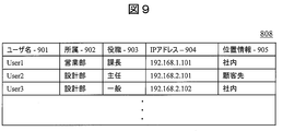
- FIG. 9 shows a structural example of the data 808 stored in the user database 807.
- the user database 807 includes, as data items, a user name 901, affiliation 902, title 903, client machine IP address 904, and location information 905 for each user.
- Information other than the position information 905 is transmitted from the client machines 803 and 811 to the management server 806 at the time of activation, and stored in the user database 807 by the management server 806.
- the management server 806 When the received user name 901 is already registered in the user database 807, the management server 806 newly receives information on the affiliation 902, post 903, and IP address 904 associated with the existing user name 901. Overwrite with. When the received user name 901 is not registered in the user database 807, the management server 806 stores the received user name 901, affiliation 902, title 903, and IP address 904 in a new row.
- the management server 806 When the management server 806 receives the location information 905 from the client machines 803 and 811, the management server 806 searches the user database 807 with the IP address 904 that is the transmission source of the location information 905, and the location received on the line where the IP address 904 matches. Information 905 is stored. In the case of the present embodiment, management position information is recorded in the position information 905.
- the IP address 904 that is the transmission source of the location information 905 is always stored in the user database 807. That is, the case where the IP address 904 that is the transmission source of the position information 905 is not stored in the user database 807 is not considered.
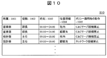
- FIG. 10 shows a structural example of the data 810 stored in the security policy database 809.
- the security policy database 809 has, as data items, affiliation 1001, title 1002, time 1003, location information 1004, and operation 1005 when applying the policy.
- management location information is recorded in the location information 1004.
- the management server 806 When the management server 806 receives malware detection information from any of the client machines 803 and 811, the management server 806 refers to the security policy database 809 and distributes the user's affiliation 1001, title 1002, and policy including the current time at which the policy is distributed.
- a security policy (operation 1005 when applying a policy) registered for the combination of the time 1003 and the position information 1004 is selected as a candidate. At this point in time, no security policy can be determined because no filtering is performed based on position information.
- the management server 806 When the combination of the time 1003 including the current time to distribute the policy, the affiliation 1001, the post 1002, and the location information 1004 is not registered in the security policy database 809, the management server 806 indicates that the operation 1005 when applying the policy is “network connection prohibited” And distribute the policy to all managed client machines.
- the administrator of the management server 806 can set an operation 1005 at the time of applying a policy for each combination of affiliation 1001, post 1002, time 1003, and position information 1004, and can change or delete data after the setting.
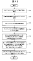
- FIG. 11 shows a processing procedure executed on the client machine 803 infected with malware. Malware infection is detected by anti-malware software 104 running on client machine 803. When detecting malware infection, the anti-malware software 104 outputs malware detection information (step 1101). Subsequently, the client processing unit 814 of the client machine 803 transmits malware detection information to the management server 806 (step 1102).
- the client processing unit 814 receives a position information acquisition request from the management server 806 (step 1103).
- the client processing unit 814 acquires position information from the GPS terminal 805, and transmits the acquired position information to the management server 806 (step 1104).
- the client processing unit 814 receives the security policy and C & C server information from the management server 806 (step 1105).
- the client processing unit 814 confirms whether the operation when applying the policy included in the received security policy is “network connection prohibited” or “C & C server connection prohibited” (step 1106).
- the client processing unit 814 disconnects the connection to the network 102 and isolates itself from the network (step 1107).
- the client processing unit 814 prohibits connection only to the address of the C & C server 101 included in the received C & C server information (step 1108). . Note that the operations after step 1103 are executed on the client machine 811 that is not infected with malware.
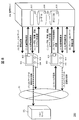
- FIG. 12 shows a processing procedure executed by the management server 806 notified of malware infection.
- the server processing unit 815 receives malware detection information from the client machine 803 (step 1201).
- the malware detection information here is the malware detection information transmitted in step 1102.
- the server processing unit 815 transmits a position information acquisition request to the client machines 803 and 811 (step 1202).
- the server processing unit 815 transmits a position information acquisition request not only to the client machine 803 that has detected the infection of malware, but also to all client machines under management.
- the server processing unit 815 receives position information from the client machines 803 and 811 (step 1203).
- the position information here is the position information transmitted in step 1104.
- the server processing unit 815 stores the received position information in the user database 807 (step 1204).
- the server processing unit 815 searches the policy database 809 based on the current time when the policy is distributed, and the security policy registered for the user having the time 1003 including the current time (operation 1005 when applying the policy). And position information 1004 are selected (step 1205).
- the server processing unit 815 compares the user location information 1004 corresponding to the security policy selected in Step 1205 with the location information 905 registered in the user database 807 (ie, the time 1003 and the matching user). The attribute and security policy of the user who satisfies both conditions of the position information 1004 are specified. Further, the server processing unit 815 determines the IP address of the user corresponding to the specified attribute and position information 905 from the user database 807 (step 1206).
- the server processing unit 815 transmits the corresponding security policy and C & C server information to the determined IP address (step 1207).
- the security policy and C & C server information here are the security policy and C & C server information received by the client machine in step 1105.
- Example 3 (3-1) System Configuration
- a security policy is determined in consideration of the number of network managers present, and a system for preventing information leakage by controlling network connection of a client machine and access to a C & C server. explain about.
- the network administrator is, for example, all staff belonging to the system department and manager staff of each department.
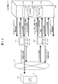
- FIG. 13 shows the overall configuration of the information leakage prevention system 300 according to the present embodiment.
- the same or similar reference numerals are given to the corresponding parts to FIG.
- the basic configuration of the information leakage prevention system 300 is the same as that of the information leakage prevention system 100 of the first embodiment.
- Each of the client machines 1303 and 1311 has a computer as a basic configuration and includes a CPU, a RAM, a ROM, a hard disk device, a network interface, and the like.
- the anti-malware software 104 and the client processing unit 1314 that are provided with functions through execution of programs by the CPU are installed in the client machines 1303 and 1311.
- the client processing unit 1314 provides a user information transmission function, a presence information processing function, a malware detection information transmission function, and a network control function through execution of a program by the CPU.
- a function different from the first embodiment is a seated information processing function.
- the presence information processing function provides a function of transmitting a response (echo reply) to the management server 1306 when the PC is activated when a presence information transmission request (ping) is received from the management server 1306.
- the management server 1306 has a computer as a basic configuration and includes a CPU, a RAM, a ROM, a hard disk device, a network interface, and the like. A display device is also connected to the management server 1306 as necessary.
- a user database (database) 1307, a security policy database (database) 1309, and a server processing unit 1315 are installed.
- the server processing unit 1315 provides a user information management function, a presence information management function, a security policy management function, and a security policy transmission function through execution of a program by the CPU.
- a function different from the first embodiment is a presence information management function.
- the presence information management function provides a function of transmitting a ping to all client machines 1303 and 1311 under management when malware detection information is received.
- the presence information management function receives a reply to ping (echo ⁇ reply)
- the presence information management function determines whether the user of the transmission source client machines 1303 and 1311 is a network administrator.
- a function of registering seat information in the user database 1307 is provided.
- the security policy transmission function of this embodiment receives C & C server information from the received malware detection information when a response (echo reply) is received from all the client machines 1303 and 1311 that transmitted the ping, or when a timeout occurs.
- the number of network managers who are present is counted from the data 1308 that is extracted and stored in the user database 1307.
- the security policy transmission function of this embodiment is based on the current time when the policy is distributed and the calculated number of network managers. Is selected from the security policy database 1309. Further, the security policy transmission function of the present embodiment extracts the IP address corresponding to the combination of affiliation and job title corresponding to the selected security policy from the user database 1307, and the security policy and C & C previously selected for the IP address. Send server information.
- FIG. 14 shows a structural example of the data 1308 stored in the user database 1307.
- the user database 1307 includes, as data items, a user name 1401, affiliation 1402, job title 1403, client machine IP address 1404, and presence information 1405 for each user.
- Information other than presence information 1405 is transmitted from the client machines 1303 and 1311 to the management server 1306 at the time of activation, and stored in the user database 1307 by the management server 1306.
- the management server 1306 When the received user name 1401 is already registered in the user database 1307, the management server 1306 displays the affiliation 1402 and the post 140 associated with the existing user name 1401. 3 and IP address 1404 are overwritten with the newly received information. When the received user name 1401 is not registered in the user database 1307, the management server 1306 stores the received user name 1401, affiliation 1402, title 1403, and IP address 1404 in a new row.
- the management server 1306 When the management server 1306 receives echo reply in response to the ping transmission, the management server 1306 searches the user database 1307 using the IP address 1404 that is the ping transmission destination, and the job title 1403 of the user whose IP address 1404 matches is the section manager. If so, “present” is stored in the presence information 1405. This function is executed by the presence information management function.
- the IP address 1404 that is the ping destination is always stored in the user database 1307. This is not considered when the IP address 1404 that is the transmission destination is not stored in the user database 1307.
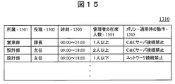
- FIG. 15 shows an example of the structure of data 1310 stored in the security policy database 1309.
- the security policy database 1308 includes, as data items, an affiliation 1501, a job title 1502, a policy distribution time 1503, a network administrator attendance 1504 necessary for applying the policy, and an operation 1505 when the policy is applied.
- the management server 1306 When the management server 1306 receives malware detection information from any of the client machines 1303 and 1310 and then receives echo reply from all of the ping destinations, or when a timeout occurs, the management server 1306 is present from the user database 1307 Count the number of network administrators inside. Further, the management server 1306 refers to the security policy database 1309 based on the number of network managers counted from the user database 1307 and the current time at which the policy is distributed, and the user's affiliation 1501, job title 1502, A security policy to be applied (operation 1505 when the policy is applied) is selected.
- the management server 1306 treats the operation 1505 when applying the policy as “network connection prohibited”, and distributes the policy to all client machines under management.
- the administrator of the management server 1306 can set an operation 1505 when applying a policy for each combination of affiliation 1501, title 1502, time 1503, and number of attendees 1504 of the administrator. Can be changed or deleted.
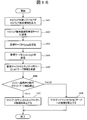
- FIG. 16 shows a processing procedure executed on the client machine 1303 infected with malware. Infection with malware is detected by the anti-malware software 104 running on the client machine 1303. When detecting malware infection, the anti-malware software 104 outputs malware detection information (step 1601). Subsequently, the client processing unit 1314 of the client machine 1303 transmits malware detection information to the management server 1306 (step 1602).
- the client processing unit 1314 receives a ping from the management server 1306 (step 1603).
- the client processing unit 1314 transmits echo reply to the management server 1306 (step 1604).
- the client processing unit 1314 receives the security policy and C & C server information from the management server 1306 (step 1605).
- the client processing unit 1314 confirms whether the operation at the time of applying the policy included in the received security policy is “network connection prohibited” or “C & C server connection prohibited” (step 1606).
- the client processing unit 1314 disconnects the connection to the network 102 and isolates itself from the network (step 1607).
- the client processing unit 1314 prohibits connection only to the address of the C & C server 101 included in the received C & C server information (step 1608). .
- the client machine 1311 that is not infected with malware executes the operations after Step 1603.
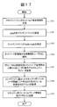
- FIG. 17 shows a processing procedure executed by the management server 1306 notified of malware infection.
- the server processing unit 1315 receives malware detection information from the client machine 1303 (step 1701).
- the malware detection information here is the malware detection information transmitted in step 1602.
- the server processing unit 1315 transmits a ping to the client machines 1303 and 1311 (step 1702). That is, the server processing unit 1315 transmits a position information acquisition request not only to the client machine 1303 that has detected the malware infection but also to all client machines under management. Thereafter, the server processing unit 1315 receives echoereply from the client machines 1303 and 1311 (step 1703).
- the echo reply here is the echo reply sent in step 1604. However, echo reply cannot be received from all of the client machines 1303 and 1311.
- the server processing unit 1315 stores the presence information of the user who uses the client machine that transmitted echo ⁇ ⁇ ⁇ ⁇ ⁇ ⁇ reply in the user database 1307 (step 1704). However, the server processing unit 1315 registers only the presence information of the network administrator in the user database 1307, and other users do not register the presence information.
- the server processing unit 1315 selects a security policy to be distributed based on a user who satisfies the combination of the current time at which the policy is distributed and the number of network administrators who are present (step 1705).
- the server processing unit 1315 compares the user information (affiliation and title) of the user corresponding to the security policy selected in step 1705 with the user information (affiliation and title) in the user database 1307, and becomes the transmission destination of each security policy.
- An IP address is determined (step 1706).
- the server processing unit 1315 transmits the corresponding security policy and C & C server information to the determined IP address (step 1707).
- the security policy and C & C server information here are the security policy and C & C server information received by the client machine in step 1605.
- the present disclosure is not limited to the above-described embodiments, and includes various modifications.
- the above-described embodiments have been described in detail for easy understanding of the present disclosure, and it is not always necessary to include all the configurations described.
- a part of one embodiment can be replaced with the configuration of another embodiment.
- the structure of another Example can also be added to the structure of a certain Example.
- a part of the configuration of another embodiment can be added, deleted, or replaced.
- each of the above-described configurations, functions, processing units, processing means, and the like may be realized by hardware by designing a part or all of them with, for example, an integrated circuit.
- Each of the above-described configurations, functions, and the like may be realized by the processor interpreting and executing a program that realizes each function (that is, in software).
- Information such as programs, tables, and files that realize each function can be stored in a storage device such as a memory, a hard disk, or an SSD (Solid State Drive), or a storage medium such as an IC card, an SD card, or a DVD.
- Control lines and information lines indicate what is considered necessary for the description, and do not represent all control lines and information lines necessary for the product. In practice, it can be considered that almost all components are connected to each other.
- 100 Information leakage prevention system, 101 ... C & C server 101 102 ... Network, 103, 111 ... client machine, 104 ... Anti-malware software, 106 ... management server, 107 ... user database, 109 ... security policy database, 114: Client processing unit, 115 ... Server processing unit, 200 ... Information leakage prevention system, 803, 211 ... client machine, 806 ... management server, 807 ... user database, 809 ... security policy database, 814 ... Client processing unit, 815 ... Server processing unit, 300 ... Information leakage prevention system, 1303, 1311 ... client machine, 1306: Management server, 1307: User database, 1309: Security policy database, 1314: Client processing unit, 1315: Server processing unit.
Abstract
Provided is an information leakage prevention technology which does not require any dedicated apparatus for administrating access on a network, and which has excellent flexibility in terms of security policy. The information leakage prevention system comprises a client terminal which has a client processing unit that performs network control in accordance with an acquired security policy, and an administrative server having: a user database which stores information about users using the client terminal; a security policy database which stores security policies for determining the network control content for each user attribute; and a server processing unit which selects a security policy on the basis of a user attribute and the time at which the security policy is distributed, and which transmits the selected security policy to a corresponding client terminal.
Description
本開示は、例えばマルウェアによる情報漏洩を未然に防止する情報漏洩防止技術に関する。
This disclosure relates to information leakage prevention technology for preventing information leakage due to malware, for example.
マルウェア対策ソフトウェアによりマルウェア感染を検知した場合に、感染したクライアントマシンからC&Cサーバへの接続をブロックし、又は、感染したクライアントマシンをネットワークから隔離することにより被害を防止するための技術として例えば特許文献1に記載の技術がある。特許文献1には、トラフィック異常を検出した場合、ファイアウォール(Firewall)装置と中継装置を使用して、特定のアドレスを宛先とするパケットを遮断する技術が記載されている。
As a technique for preventing damage by blocking the connection from an infected client machine to the C & C server or isolating the infected client machine from the network when malware infection is detected by anti-malware software, for example, Patent Literature There is a technique described in 1. Japanese Patent Application Laid-Open No. 2004-151561 describes a technique for blocking a packet destined for a specific address using a firewall device and a relay device when a traffic abnormality is detected.
しかし、特許文献1に記載の技術は、外部ネットワークとクライアントマシンの間にファイアウォール装置と中継装置が存在することを前提としており、クライアントマシンをファイアウォール装置と中継装置が存在する特定の内部ネットワークに設置する必要がある。このため、内部ネットワークの外に位置するクライアントマシンからの情報漏洩を防ぐことはできない。
However, the technique described in Patent Document 1 is based on the assumption that a firewall device and a relay device exist between an external network and a client machine, and the client machine is installed in a specific internal network where the firewall device and the relay device exist. There is a need to. For this reason, information leakage from client machines located outside the internal network cannot be prevented.
また、特許文献1に記載の技術は、ファイアウォール装置と中継装置を使用して、外部へのアクセスを一律に制限する。このため、内部ネットワークに存在する全てのクライアントマシンに対して同じレベルの対策しかできない。また、各クライアントマシンを使用するユーザによってセキュリティの強度を変更し、安全と認められる範囲内でネットワーク接続を許可し、ユーザの利用制限を軽減するなどの柔軟な対応ができない。
In addition, the technology described in Patent Document 1 uses a firewall device and a relay device to uniformly limit access to the outside. For this reason, only the same level of countermeasures can be taken for all client machines existing in the internal network. In addition, it is impossible to flexibly cope with such a case that the security strength is changed by a user who uses each client machine, a network connection is permitted within a range that is recognized as safe, and the use restriction of the user is reduced.
上記課題を解決するために、本開示は、例えば請求の範囲に記載の構成を採用する。本明細書は上記課題を解決する手段を複数含んでいるが、その一例を挙げるならば、「取得したセキュリティポリシーに応じてネットワーク制御を行うクライアント処理部を有するクライアント端末と、前記クライアント端末を利用するユーザに関する情報を格納するユーザデータベースと、ユーザの属性ごとにネットワーク制御内容を定めたセキュリティポリシーを格納するセキュリティポリシーデータベースと、ユーザの属性及び前記セキュリティポリシーを配布する時刻に基づいて前記セキュリティポリシーを選択し、選択された前記セキュリティポリシーを対応する前記クライアント端末に送信するサーバ処理部と、を有する管理サーバとを有する情報漏洩防止システム。」を特徴とする。
In order to solve the above problems, the present disclosure employs, for example, the configuration described in the claims. The present specification includes a plurality of means for solving the above-described problems. To give an example, a client terminal having a client processing unit that performs network control in accordance with an acquired security policy and the client terminal are used. A user database for storing information about the user to perform, a security policy database for storing a security policy that defines network control content for each user attribute, and the security policy based on the user attribute and the time at which the security policy is distributed. An information leakage prevention system comprising: a management server having a server processing unit that selects and transmits the selected security policy to the corresponding client terminal. "
本開示によれば、ファイアウォール装置や中継装置が存在しないネットワークでも、クライアント端末からC&Cサーバへの情報送信をブロックし又はクライアント端末をネットワークから隔離することができる。また、本開示によれば、クライアント端末のユーザの属性に応じてセキュリティポリシーの強弱を変化させることができる。前述した以外の課題、構成及び効果は、以下の実施の形態の説明により明らかにされる。
According to the present disclosure, it is possible to block information transmission from the client terminal to the C & C server or to isolate the client terminal from the network even in a network where there is no firewall device or relay device. Moreover, according to this indication, the strength of a security policy can be changed according to the attribute of the user of a client terminal. Problems, configurations, and effects other than those described above will become apparent from the following description of embodiments.
以下、図面に基づいて、本開示の実施の形態を説明する。なお、本開示の実施の態様は、後述する形態例に限定されるものではなく、その技術思想の範囲において、種々の変形が可能である。
Hereinafter, embodiments of the present disclosure will be described based on the drawings. Note that the embodiments of the present disclosure are not limited to the embodiments described below, and various modifications are possible within the scope of the technical idea.
(1)実施例1
(1-1)システム構成
図1は、本実施例に係る情報漏洩防止システム100の全体構成を示す。情報漏洩防止システム100は、クライアントマシンと管理サーバの協働により、クライアントマシンのネットワーク接続やC&Cサーバへのアクセスを制御し、マルウェアの感染による情報漏洩を防止するシステムである。 (1) Example 1
(1-1) System Configuration FIG. 1 shows an overall configuration of an informationleakage prevention system 100 according to the present embodiment. The information leakage prevention system 100 is a system that controls the client machine's network connection and access to the C & C server by cooperation between the client machine and the management server, and prevents information leakage due to malware infection.
(1-1)システム構成
図1は、本実施例に係る情報漏洩防止システム100の全体構成を示す。情報漏洩防止システム100は、クライアントマシンと管理サーバの協働により、クライアントマシンのネットワーク接続やC&Cサーバへのアクセスを制御し、マルウェアの感染による情報漏洩を防止するシステムである。 (1) Example 1
(1-1) System Configuration FIG. 1 shows an overall configuration of an information
情報漏洩防止システム100は、管理サーバ106とクライアントマシン103及び111を有している。管理サーバ106とクライアントマシン103及び111は、ネットワーク102を通じて接続されている。図1では、クライアントマシン103及び111のみを表しているが、クライアントマシンの台数は任意である。
The information leakage prevention system 100 includes a management server 106 and client machines 103 and 111. The management server 106 and the client machines 103 and 111 are connected through the network 102. In FIG. 1, only the client machines 103 and 111 are shown, but the number of client machines is arbitrary.
クライアントマシン103及び111はそれぞれ、コンピュータを基本構成とし、CPU、RAM、ROM、ハードディスク装置、ネットワークインタフェース、ディスプレイ装置等で構成される。本実施例の場合、クライアントマシン103及び111には、CPUによるプログラムの実行を通じて機能が提供されるマルウェア対策ソフトウェア104とクライアント処理部114が実装されている。マルウェア対策ソフトウェア104は、マルウェアの感染を検知するプログラムである。
Each of the client machines 103 and 111 has a computer as a basic configuration and includes a CPU, a RAM, a ROM, a hard disk device, a network interface, a display device, and the like. In the case of the present embodiment, the anti-malware software 104 and the client processing unit 114 that are provided with functions through execution of programs by the CPU are installed in the client machines 103 and 111. The anti-malware software 104 is a program that detects malware infection.
クライアント処理部114は、ユーザ情報送信機能、マルウェア検知情報送信機能、ネットワーク制御機能を含む。ユーザ情報送信機能はユーザ情報の送信に使用され、マルウェア検知情報送信機能はマルウェア検知情報の送信に使用され、ネットワーク制御機能はネットワーク等との接続又は切断を制御する。
The client processing unit 114 includes a user information transmission function, a malware detection information transmission function, and a network control function. The user information transmission function is used for transmitting user information, the malware detection information transmission function is used for transmission of malware detection information, and the network control function controls connection or disconnection with a network or the like.
管理サーバ106は、コンピュータを基本構成とし、CPU、RAM、ROM、ハードディスク装置、ネットワークインタフェース等で構成される。管理サーバ106には必要に応じて表示装置も接続される。本実施例の管理サーバ106には、ユーザデータベース(データベース)107、セキュリティポリシーデータベース(DB)109、サーバ処理部115が実装されている。
The management server 106 has a computer as a basic configuration and includes a CPU, a RAM, a ROM, a hard disk device, a network interface, and the like. A display device is also connected to the management server 106 as necessary. The management server 106 according to the present embodiment includes a user database (database) 107, a security policy database (DB) 109, and a server processing unit 115.
サーバ処理部115は、CPUによるプログラムの実行を通じ、ユーザ情報管理機能、セキュリティポリシー管理機能、セキュリティポリシー送信機能を提供する。ユーザ情報管理機能はユーザデータベース107を管理し、セキュリティポリシー管理機能はセキュリティポリシーデータベース109を管理し、セキュリティポリシー送信機能はセキュリティポリシーの送信に使用される。
The server processing unit 115 provides a user information management function, a security policy management function, and a security policy transmission function through execution of a program by the CPU. The user information management function manages the user database 107, the security policy management function manages the security policy database 109, and the security policy transmission function is used for transmission of the security policy.
ユーザデータベース107には、各ユーザのユーザ名(又は識別子)、所属、役職、クライアントマシンのIPアドレス等のデータ108が保存される。本明細書では、これら情報をまとめて「ユーザに関する情報」ともいう。また、各ユーザのユーザ名(又は識別子)、所属、役職をまとめて「ユーザ情報」ともいう。また、本実施例では、各ユーザの所属、役職、ポリシーを配布する時刻をまとめて「属性」ともいう。セキュリティポリシーデータベース109には、所属、役職、ポリシーを配布する時刻、ポリシー適用時の動作等を記述したデータ110が保存される。
The user database 107 stores data 108 such as the user name (or identifier), affiliation, title, and IP address of the client machine of each user. In this specification, these pieces of information are collectively referred to as “information about the user”. Also, the user name (or identifier), affiliation, and title of each user are collectively referred to as “user information”. In this embodiment, the affiliation, title, and policy distribution time of each user are also collectively referred to as “attributes”. The security policy database 109 stores data 110 describing affiliation, title, policy distribution time, policy application operation, and the like.
以下では、情報漏洩防止システム100で実行される通信や動作の概略を説明する。なお、以下の動作1~5は、図中の(1)~(5)に対応している。
In the following, an outline of communication and operations executed in the information leakage prevention system 100 will be described. The following operations 1 to 5 correspond to (1) to (5) in the figure.
・動作1
ユーザによって起動されたクライアントマシン103及び111は、予め登録されているユーザの情報(ユーザ名、所属、役職)と自機のIPアドレス(起動時)を管理サーバ106に送信する。クライアントマシン103及び111は、登録されているユーザ名、所属、役職、IPアドレスのいずれかに変更があった場合、変更後のユーザ名、所属、役職、IPアドレス(更新後)を管理サーバ106に送信する。管理サーバ106は、クライアントマシン103及び111から各ユーザのユーザ名、所属、役職、IPアドレスの情報を受信すると、それらをユーザデータベース107に格納する。 ・ Operation 1
The client machines 103 and 111 activated by the user transmit user information (user name, affiliation, title) registered in advance and the IP address (at the time of activation) of the own machine to the management server 106. When any of the registered user name, affiliation, title, and IP address is changed, the client machines 103 and 111 indicate the changed user name, affiliation, title, and IP address (after update) to the management server 106. Send to. When the management server 106 receives information on the user name, affiliation, title, and IP address of each user from the client machines 103 and 111, the management server 106 stores them in the user database 107.
ユーザによって起動されたクライアントマシン103及び111は、予め登録されているユーザの情報(ユーザ名、所属、役職)と自機のIPアドレス(起動時)を管理サーバ106に送信する。クライアントマシン103及び111は、登録されているユーザ名、所属、役職、IPアドレスのいずれかに変更があった場合、変更後のユーザ名、所属、役職、IPアドレス(更新後)を管理サーバ106に送信する。管理サーバ106は、クライアントマシン103及び111から各ユーザのユーザ名、所属、役職、IPアドレスの情報を受信すると、それらをユーザデータベース107に格納する。 ・ Operation 1
The
・動作2及び3
例えばクライアントマシン103がマルウェアに感染した場合、クライアントマシン103は、マルウェア対策ソフトウェア104が出力するマルウェア検知情報を管理サーバ106へ送信する。マルウェア検知情報には、検知日時とマルウェアの通信先であるC&Cサーバ情報が含まれる。 ・ Operations 2 and 3
For example, when theclient machine 103 is infected with malware, the client machine 103 transmits malware detection information output from the anti-malware software 104 to the management server 106. The malware detection information includes detection date and time and C & C server information that is a communication destination of the malware.
例えばクライアントマシン103がマルウェアに感染した場合、クライアントマシン103は、マルウェア対策ソフトウェア104が出力するマルウェア検知情報を管理サーバ106へ送信する。マルウェア検知情報には、検知日時とマルウェアの通信先であるC&Cサーバ情報が含まれる。 ・ Operations 2 and 3
For example, when the
・動作4
管理サーバ106は、マルウェア検知情報を受信した場合、当該検知情報からC&Cサーバ情報を摘出する。次に、管理サーバ106は、ポリシーを配布する現在時刻を特定し、特定した現在時刻でセキュリティポリシーデータベース109に格納されているデータ110を検索する。ここで、管理サーバ106は、現在時刻に関連する所属と役職の組み合わせについて登録されているセキュリティポリシーを選定する。また、管理サーバ106は、ユーザデータベース107に格納されているデータ108の中から、現在時刻に関連する所属と役職の組み合わせに対応する各IPアドレスを摘出し、当該IPアドレスに宛てて、各ユーザに対応するセキュリティポリシーとC&Cサーバ情報を送信する。ここでの送信先は、マルウェアに感染したクライアントマシン103に限定されない。図1の場合は、クライアントマシン103及び111のいずれもがセキュリティポリシーとC&Cサーバ情報の送信先となる。 ・ Operation 4
When the management server 106 receives malware detection information, the management server 106 extracts C & C server information from the detection information. Next, the management server 106 specifies the current time at which the policy is distributed, and searches thedata 110 stored in the security policy database 109 at the specified current time. Here, the management server 106 selects a security policy registered for a combination of affiliation and post related to the current time. In addition, the management server 106 extracts each IP address corresponding to the combination of affiliation and title related to the current time from the data 108 stored in the user database 107, and sends each IP address to the IP address. A security policy and C & C server information corresponding to is transmitted. The transmission destination here is not limited to the client machine 103 infected with malware. In the case of FIG. 1, both of the client machines 103 and 111 are transmission destinations of the security policy and C & C server information.
管理サーバ106は、マルウェア検知情報を受信した場合、当該検知情報からC&Cサーバ情報を摘出する。次に、管理サーバ106は、ポリシーを配布する現在時刻を特定し、特定した現在時刻でセキュリティポリシーデータベース109に格納されているデータ110を検索する。ここで、管理サーバ106は、現在時刻に関連する所属と役職の組み合わせについて登録されているセキュリティポリシーを選定する。また、管理サーバ106は、ユーザデータベース107に格納されているデータ108の中から、現在時刻に関連する所属と役職の組み合わせに対応する各IPアドレスを摘出し、当該IPアドレスに宛てて、各ユーザに対応するセキュリティポリシーとC&Cサーバ情報を送信する。ここでの送信先は、マルウェアに感染したクライアントマシン103に限定されない。図1の場合は、クライアントマシン103及び111のいずれもがセキュリティポリシーとC&Cサーバ情報の送信先となる。 ・ Operation 4
When the management server 106 receives malware detection information, the management server 106 extracts C & C server information from the detection information. Next, the management server 106 specifies the current time at which the policy is distributed, and searches the
・動作5
セキュリティポリシーとC&Cサーバ情報を受信したクライアントマシン103及び111は、受信したセキュリティポリシーの内容に応じ、C&Cサーバ101との接続を切断し、又は、ネットワーク102との接続を切断する。図1の場合、クライアントマシン103はネットワーク102との接続を切断し、クライアントマシン111はC&Cサーバ101との接続のみ切断する(ネットワークとの接続は維持する)。 ・ Operation 5
The client machines 103 and 111 that have received the security policy and the C & C server information disconnect the connection with the C & C server 101 or the network 102 according to the content of the received security policy. In the case of FIG. 1, the client machine 103 disconnects the connection with the network 102, and the client machine 111 disconnects only the connection with the C & C server 101 (maintains the connection with the network).
セキュリティポリシーとC&Cサーバ情報を受信したクライアントマシン103及び111は、受信したセキュリティポリシーの内容に応じ、C&Cサーバ101との接続を切断し、又は、ネットワーク102との接続を切断する。図1の場合、クライアントマシン103はネットワーク102との接続を切断し、クライアントマシン111はC&Cサーバ101との接続のみ切断する(ネットワークとの接続は維持する)。 ・ Operation 5
The
(1-2)ユーザデータベースの構成
図2に、ユーザデータベース107に格納されているデータ108の構造例を示す。ユーザデータベース107は、データ項目として、各ユーザのユーザ名201、所属202、役職203、クライアントマシンのIPアドレス204を有している。これらの情報は、起動時に、クライアントマシン103及び111から管理サーバ106に送信され、管理サーバ106により対応する項目位置に格納される。 (1-2) Configuration of User Database FIG. 2 shows a structural example of thedata 108 stored in the user database 107. The user database 107 includes, as data items, a user name 201, an affiliation 202, a job title 203, and an IP address 204 of the client machine for each user. These pieces of information are transmitted from the client machines 103 and 111 to the management server 106 at the time of activation, and are stored in corresponding item positions by the management server 106.
図2に、ユーザデータベース107に格納されているデータ108の構造例を示す。ユーザデータベース107は、データ項目として、各ユーザのユーザ名201、所属202、役職203、クライアントマシンのIPアドレス204を有している。これらの情報は、起動時に、クライアントマシン103及び111から管理サーバ106に送信され、管理サーバ106により対応する項目位置に格納される。 (1-2) Configuration of User Database FIG. 2 shows a structural example of the
受信したユーザ名201がユーザデータベース107に既に登録されている場合、管理サーバ106は、既存のユーザ名201に紐付けられている所属202、役職203及びIPアドレス204の情報を新たに受信した情報で上書きする。受信したユーザ名201がユーザデータベース107に登録されていない場合、管理サーバ106は、受信したユーザ名201、所属202、役職203、IPアドレス204を新たな行に格納する。管理サーバ106の管理者は、不要となった行をユーザデータベース107から削除することもできる。
When the received user name 201 is already registered in the user database 107, the management server 106 newly receives information on the affiliation 202, post 203, and IP address 204 associated with the existing user name 201. Overwrite with. When the received user name 201 is not registered in the user database 107, the management server 106 stores the received user name 201, affiliation 202, title 203, and IP address 204 in a new line. The administrator of the management server 106 can delete unnecessary rows from the user database 107.
(1-3)セキュリティポリシーデータベースの構成
図3に、セキュリティポリシーデータベース109に格納されているデータ110の構造例を示す。セキュリティポリシーデータベース109は、データ項目として、所属301、役職302、ポリシーを配布する時刻303、ポリシー適用時の動作304を有している。 (1-3) Configuration of Security Policy Database FIG. 3 shows an example of the structure of thedata 110 stored in the security policy database 109. The security policy database 109 has, as data items, an affiliation 301, a post 302, a policy distribution time 303, and a policy application operation 304.
図3に、セキュリティポリシーデータベース109に格納されているデータ110の構造例を示す。セキュリティポリシーデータベース109は、データ項目として、所属301、役職302、ポリシーを配布する時刻303、ポリシー適用時の動作304を有している。 (1-3) Configuration of Security Policy Database FIG. 3 shows an example of the structure of the
管理サーバ106は、クライアントマシン103及び111のいずれかからマルウェア検知情報を受信した場合、ポリシーを配布する現在時刻でセキュリティポリシーデータベース109を検索し、前記現在時刻を含む時刻303に含むユーザ(所属301と役職302の各組み合わせで特定される)に適用するセキュリティポリシー(ポリシー適用時の動作304)を選定する。
When the malware detection information is received from either of the client machines 103 and 111, the management server 106 searches the security policy database 109 at the current time for distributing the policy, and includes the user (affiliation 301) included in the time 303 including the current time. And a security policy (operation 304 at the time of policy application) to be applied is selected.
ポリシーを配布する現在時刻を含む時刻303に紐付けられた所属301及び役職302の組み合わせがセキュリティポリシーデータベース109に登録されていない場合、管理サーバ106は、ポリシー適用時の動作304が「ネットワーク接続禁止」であるものとして扱い、管理下にある全てのクライアントマシンに当該ポリシーを配布する。「ネットワーク接続禁止」は、最も厳しい動作である。管理サーバ106の管理者は、所属301、役職302及び時刻303の組み合わせ毎に、ポリシー適用時の動作304を設定することができ、その設定後も、データを変更又は削除できる。
When the combination of the affiliation 301 and the post 302 associated with the time 303 including the current time at which the policy is distributed is not registered in the security policy database 109, the management server 106 indicates that the operation 304 at the time of applying the policy is “prohibit network connection”. And distribute the policy to all managed client machines. “Prohibit network connection” is the most severe operation. The administrator of the management server 106 can set the operation 304 when applying the policy for each combination of the affiliation 301, the post 302, and the time 303, and can change or delete the data even after the setting.
(1-4)処理動作
(1-4-1)クライアントマシン起動時の動作
図4に、クライアントマシン起動時にクライアントマシン103及び111で実行される処理手順を示す。ユーザによってクライアントマシン103及び111が起動されると(ステップ401)、クライアント処理部114はOS(Operation System)にログインする(ステップ402)。次に、クライアント処理部114は、自身のIPアドレスを取得する(ステップ403)。続いて、クライアント処理部114は、ステップ403で取得した自身のIPアドレスと、予め登録されているユーザのユーザ情報(ユーザ名、所属、役職の情報)とを管理サーバ106に送信する(ステップ404)。 (1-4) Processing Operation (1-4-1) Operation when Client Machine is Started FIG. 4 shows a processing procedure executed by the client machines 103 and 111 when the client machine is started. When the client machines 103 and 111 are activated by the user (step 401), the client processing unit 114 logs in to an OS (Operation System) (step 402). Next, the client processing unit 114 acquires its own IP address (step 403). Subsequently, the client processing unit 114 transmits the own IP address acquired in step 403 and user information (user name, affiliation, job title information) registered in advance to the management server 106 (step 404). ).
(1-4-1)クライアントマシン起動時の動作
図4に、クライアントマシン起動時にクライアントマシン103及び111で実行される処理手順を示す。ユーザによってクライアントマシン103及び111が起動されると(ステップ401)、クライアント処理部114はOS(Operation System)にログインする(ステップ402)。次に、クライアント処理部114は、自身のIPアドレスを取得する(ステップ403)。続いて、クライアント処理部114は、ステップ403で取得した自身のIPアドレスと、予め登録されているユーザのユーザ情報(ユーザ名、所属、役職の情報)とを管理サーバ106に送信する(ステップ404)。 (1-4) Processing Operation (1-4-1) Operation when Client Machine is Started FIG. 4 shows a processing procedure executed by the
図5に、クライアントマシン起動時に管理サーバ106で実行される処理手順を示す。管理サーバ106のサーバ処理部115は、クライアントマシン103及び111からIPアドレスとユーザ情報を受信する(ステップ501)。ここでのユーザ情報は、前記ステップ404で送信されたユーザ情報である。次に、サーバ処理部115は、受信したユーザ情報に含まれるユーザ名がユーザデータベース107に登録されているか否か確認する(ステップ502)。ユーザ名がユーザデータベース107に登録されている場合、サーバ処理部115は、前記ユーザ名に対応付けられている所属202、役職203及びIPアドレス204の各情報を、受信したユーザ情報の内容で上書き更新する(ステップ503)。一方、ユーザ名がユーザデータベース107に登録されていない場合、サーバ処理部115は、受信したユーザ情報の内容をユーザデータベース107に新規登録する(ステップ504)。
FIG. 5 shows a processing procedure executed by the management server 106 when the client machine is activated. The server processing unit 115 of the management server 106 receives the IP address and user information from the client machines 103 and 111 (step 501). The user information here is the user information transmitted in step 404. Next, the server processing unit 115 checks whether or not the user name included in the received user information is registered in the user database 107 (step 502). When the user name is registered in the user database 107, the server processing unit 115 overwrites each information of the affiliation 202, post 203, and IP address 204 associated with the user name with the contents of the received user information. Update (step 503). On the other hand, if the user name is not registered in the user database 107, the server processing unit 115 newly registers the content of the received user information in the user database 107 (step 504).
(1-4-2)マルウェア感染時の動作
図6に、マルウェアに感染したクライアントマシン103で実行される処理手順を示す。マルウェアへの感染は、クライアントマシン103で実行中のマルウェア対策ソフトウェア104によって検知される。マルウェアの感染を検知すると、マルウェア対策ソフトウェア104は、マルウェア検知情報を出力する(ステップ601)。続いて、クライアントマシン103のクライアント処理部114が、マルウェア検知情報を管理サーバ106に送信する(ステップ602)。 (1-4-2) Operation at Malware Infection FIG. 6 shows a processing procedure executed on theclient machine 103 infected with malware. Malware infection is detected by the anti-malware software 104 running on the client machine 103. When detecting malware infection, the anti-malware software 104 outputs malware detection information (step 601). Subsequently, the client processing unit 114 of the client machine 103 transmits malware detection information to the management server 106 (step 602).
図6に、マルウェアに感染したクライアントマシン103で実行される処理手順を示す。マルウェアへの感染は、クライアントマシン103で実行中のマルウェア対策ソフトウェア104によって検知される。マルウェアの感染を検知すると、マルウェア対策ソフトウェア104は、マルウェア検知情報を出力する(ステップ601)。続いて、クライアントマシン103のクライアント処理部114が、マルウェア検知情報を管理サーバ106に送信する(ステップ602)。 (1-4-2) Operation at Malware Infection FIG. 6 shows a processing procedure executed on the
その後、クライアント処理部114は、管理サーバ106からセキュリティポリシーとC&Cサーバ情報を受信する(ステップ603)。ここで、クライアント処理部114は、受信したセキュリティポリシーに含まれるポリシー適用時の動作が、「ネットワーク接続禁止」か「C&Cサーバ接続禁止」かを確認する(ステップ604)。ポリシー適用時の動作が「ネットワーク接続禁止」であった場合、クライアント処理部114は、ネットワーク102への接続を切断し、自身をネットワークから隔離する(ステップ605)。一方、ポリシー適用時の動作が「C&Cサーバ接続禁止」であった場合、クライアント処理部114は、受信したC&Cサーバ情報に含まれるC&Cサーバ101のアドレスに対してのみ接続を禁止する(ステップ606)。なお、マルウェアに感染していないクライアントマシン111では、ステップ603以降の動作が実行される。
Thereafter, the client processing unit 114 receives the security policy and C & C server information from the management server 106 (step 603). Here, the client processing unit 114 confirms whether the operation at the time of applying the policy included in the received security policy is “network connection prohibited” or “C & C server connection prohibited” (step 604). If the operation at the time of applying the policy is “network connection prohibited”, the client processing unit 114 disconnects the connection to the network 102 and isolates itself from the network (step 605). On the other hand, when the operation at the time of applying the policy is “C & C server connection prohibited”, the client processing unit 114 prohibits connection only to the address of the C & C server 101 included in the received C & C server information (step 606). . Note that the operation after step 603 is executed in the client machine 111 that is not infected with malware.
図7に、マルウェアへの感染が通知された管理サーバ106で実行される処理手順を示す。サーバ処理部115は、クライアントマシン103からマルウェア検知情報を受信する(ステップ701)。ここでのマルウェア検知情報は、前記ステップ602で送信されたマルウェア検知情報である。次に、サーバ処理部115は、ポリシーを配布する現在時刻に基づいてポリシーデータベース109を検索し、前記現在時刻を含む時刻303を有する所属と役職の組み合わせ毎に、配布するセキュリティポリシー(ポリシー適用時の動作304)を選定する(ステップ702)。ここでは、複数の組み合わせが選定され得る。
FIG. 7 shows a processing procedure executed by the management server 106 that is notified of malware infection. The server processing unit 115 receives malware detection information from the client machine 103 (step 701). The malware detection information here is the malware detection information transmitted in step 602. Next, the server processing unit 115 searches the policy database 109 based on the current time at which the policy is distributed, and distributes the security policy (at the time of policy application) for each combination of affiliation and post having the time 303 including the current time. Operation 304) is selected (step 702). Here, a plurality of combinations can be selected.
次に、サーバ処理部115は、セキュリティポリシーが選定されたユーザを特定する所属及び役職の組み合わせと、ユーザデータベース107の所属と役職の組み合わせとを比較し、各ユーザに配布するセキュリティポリシーの送信先のIPアドレスを決定する(ステップ703)。この後、サーバ処理部115は、決定されたIPアドレスに宛てて、対応するセキュリティポリシーとC&Cサーバ情報を送信する(ステップ704)。ここでのセキュリティポリシーとC&Cサーバ情報は、前記ステップ603でクライアントマシンが受信したセキュリティポリシーとC&Cサーバ情報である。
Next, the server processing unit 115 compares the combination of affiliation and position that identifies the user for whom the security policy is selected with the combination of affiliation and position in the user database 107, and sends the transmission destination of the security policy distributed to each user. Is determined (step 703). Thereafter, the server processing unit 115 transmits the corresponding security policy and C & C server information to the determined IP address (step 704). The security policy and C & C server information here are the security policy and C & C server information received by the client machine in step 603.
(1-5)まとめ
前述したように、本実施例の情報漏洩防止システム100を構成するネットワーク102には、ファイアウォール装置も中継装置も存在しないが、クライアントマシン103及び111からC&Cサーバ101への情報送信をブロックし又はクライアントマシン103及び111をネットワーク102から隔離することができる。また、クライアントマシン103及び111に適用されるセキュリティポリシー(ポリシー適用時の動作)は、ユーザの所属と役職の組み合わせに応じて決定することができる。すなわち、クライアントマシン103及び111を使用するユーザの属性に応じてセキュリティポリシーの強弱を変化させることができる。 (1-5) Summary As described above, there is no firewall device or relay device in thenetwork 102 constituting the information leakage prevention system 100 of the present embodiment, but information from the client machines 103 and 111 to the C & C server 101 is information. Transmission can be blocked or client machines 103 and 111 can be isolated from the network 102. Further, the security policy (operation when applying a policy) applied to the client machines 103 and 111 can be determined according to the combination of the user's affiliation and job title. That is, the strength of the security policy can be changed according to the attribute of the user who uses the client machines 103 and 111.
前述したように、本実施例の情報漏洩防止システム100を構成するネットワーク102には、ファイアウォール装置も中継装置も存在しないが、クライアントマシン103及び111からC&Cサーバ101への情報送信をブロックし又はクライアントマシン103及び111をネットワーク102から隔離することができる。また、クライアントマシン103及び111に適用されるセキュリティポリシー(ポリシー適用時の動作)は、ユーザの所属と役職の組み合わせに応じて決定することができる。すなわち、クライアントマシン103及び111を使用するユーザの属性に応じてセキュリティポリシーの強弱を変化させることができる。 (1-5) Summary As described above, there is no firewall device or relay device in the
(2)実施例2
(2-1)システム構成
本実施例では、クライアントマシンの位置情報を加味してセキュリティポリシーを決定し、クライアントマシンのネットワーク接続やC&Cサーバへのアクセスを制御し、情報漏洩を防止するシステムついて説明する。図8に、本実施例に係る情報漏洩防止システム200の全体構成を示す。図8には、図1との対応部分に同一又は類似の符号を付して示す。図8より分かるように、情報漏洩防止システム200の基本構成は、実施例1の情報漏洩防止システム100と同じである。 (2) Example 2
(2-1) System Configuration In this embodiment, a system that determines the security policy in consideration of the location information of the client machine, controls the client machine's network connection and access to the C & C server, and prevents information leakage is described. To do. FIG. 8 shows the overall configuration of the informationleakage prevention system 200 according to the present embodiment. In FIG. 8, the same or similar reference numerals are given to the corresponding parts to FIG. As can be seen from FIG. 8, the basic configuration of the information leakage prevention system 200 is the same as the information leakage prevention system 100 of the first embodiment.
(2-1)システム構成
本実施例では、クライアントマシンの位置情報を加味してセキュリティポリシーを決定し、クライアントマシンのネットワーク接続やC&Cサーバへのアクセスを制御し、情報漏洩を防止するシステムついて説明する。図8に、本実施例に係る情報漏洩防止システム200の全体構成を示す。図8には、図1との対応部分に同一又は類似の符号を付して示す。図8より分かるように、情報漏洩防止システム200の基本構成は、実施例1の情報漏洩防止システム100と同じである。 (2) Example 2
(2-1) System Configuration In this embodiment, a system that determines the security policy in consideration of the location information of the client machine, controls the client machine's network connection and access to the C & C server, and prevents information leakage is described. To do. FIG. 8 shows the overall configuration of the information
クライアントマシン803及び811はそれぞれ、コンピュータを基本構成とし、CPU、RAM、ROM、ハードディスク装置、ネットワークインタフェース等で構成される。本実施例の場合、クライアントマシン803及び811には、CPUによるプログラムの実行を通じて機能が提供されるマルウェア対策ソフトウェア104とクライアント処理部814が実装されている。本実施例のクライアントマシン803及び811には、更にGPS端末805が実装されている。GPS端末805はクライアントマシン803に対して外付けされてもよい。GPS端末805は、各クライアントマシン803及び811の物理的な位置情報(緯度、経度、高度)を取得している。
Each of the client machines 803 and 811 has a computer as a basic configuration and includes a CPU, a RAM, a ROM, a hard disk device, a network interface, and the like. In the case of the present embodiment, the anti-malware software 104 and the client processing unit 814 that are provided with functions through execution of programs by the CPU are installed in the client machines 803 and 811. A GPS terminal 805 is further mounted on the client machines 803 and 811 of this embodiment. The GPS terminal 805 may be externally attached to the client machine 803. The GPS terminal 805 acquires physical position information (latitude, longitude, altitude) of the client machines 803 and 811.
クライアント処理部814は、CPUによるプログラムの実行を通じ、ユーザ情報送信機能、位置情報処理機能、マルウェア検知情報送信機能、ネットワーク制御機能を提供する。このうち、実施例1と異なる機能は、位置情報処理機能である。位置情報処理機能は、位置情報の要求に応じてGPS端末805から現在の位置情報を取得し、要求元(管理サーバ806)に送信する。クライアント処理部814が物理的な位置情報を管理上の位置情報(例えば社内、社外、顧客先、社員宅等)に変換するテーブルを有している場合、位置情報として管理上の位置情報を送信してもよい。変換に用いるテーブルは、クライアント処理部814内に事前に登録されていてもよいし、管理サーバ806から通知されてもよい。
The client processing unit 814 provides a user information transmission function, a position information processing function, a malware detection information transmission function, and a network control function through execution of a program by the CPU. Among these, a function different from the first embodiment is a position information processing function. The position information processing function acquires the current position information from the GPS terminal 805 in response to the request for position information, and transmits it to the request source (management server 806). When the client processing unit 814 has a table for converting physical position information into management position information (for example, inside, outside, customer, employee's house, etc.), the management position information is transmitted as the position information. May be. The table used for conversion may be registered in advance in the client processing unit 814, or may be notified from the management server 806.
管理サーバ806は、コンピュータを基本構成とし、CPU、RAM、ROM、ハードディスク装置、ネットワークインタフェース等で構成される。管理サーバ106には必要に応じて表示装置も接続される。本実施例の管理サーバ806には、ユーザデータベース(データベース)807、セキュリティポリシーデータベース(DB)809、サーバ処理部815が実装されている。
The management server 806 has a computer as a basic configuration and includes a CPU, a RAM, a ROM, a hard disk device, a network interface, and the like. A display device is also connected to the management server 106 as necessary. In the management server 806 of this embodiment, a user database (database) 807, a security policy database (DB) 809, and a server processing unit 815 are installed.
サーバ処理部815は、CPUによるプログラムの実行を通じ、ユーザ情報管理機能、位置情報管理機能、セキュリティポリシー管理機能、セキュリティポリシー送信機能を提供する。このうち、実施例1と異なる機能は、位置情報管理機能である。位置情報管理機能は、マルウェア検知情報を受信した場合に、クライアントマシン803及び811に対して現在の位置情報を要求する。位置情報管理機能は、クライアントマシン803及び811から位置情報を受信した場合、受信した位置情報をユーザデータベース807に登録する。位置情報管理機能は、GPS端末805が出力するGPS情報をそのまま位置情報として受信する場合、物理的な位置情報であるGPS情報を管理上の位置情報に変換し、ユーザデータベース807に登録する。なお、位置情報管理機能にGPS情報を管理上の位置情報に変換するテーブルをクライアントマシン803及び811に送信する機能を実装してもよい。
The server processing unit 815 provides a user information management function, a location information management function, a security policy management function, and a security policy transmission function through execution of a program by the CPU. Among these, a function different from the first embodiment is a position information management function. The location information management function requests the current location information from the client machines 803 and 811 when malware detection information is received. When the position information management function receives position information from the client machines 803 and 811, the position information management function registers the received position information in the user database 807. When the GPS information output from the GPS terminal 805 is received as position information as it is, the position information management function converts the GPS information, which is physical position information, into management position information and registers it in the user database 807. Note that a function for transmitting a table for converting GPS information to management position information to the client machines 803 and 811 may be implemented in the position information management function.
本実施例の場合、管理サーバ806のサーバ処理部815は、マルウェア検知情報を受信すると、マルウェア検知情報からC&Cサーバ情報を摘出する。また、サーバ処理部815は、ポリシーを配布する現在時刻に基づいてセキュリティポリシーデータベース809のデータ810を検索する。ここで、管理サーバ806は、現在時刻に関連する所属と役職の組み合わせについて登録されているセキュリティポリシーの候補と位置情報の組み合わせを選定する。また、管理サーバ806は、選定された組み合わせの位置情報と受信した位置情報を照合し、一致する位置情報を含む組み合わせに体操するセキュリティポリシーを該当するユーザに適用するセキュリティポリシーに決定する。また、管理サーバ806は、決定された組み合わせの所属と役職に対応するIPアドレスをユーザデータベース807から摘出し、当該IPアドレスに宛てて、各ユーザに対応するセキュリティポリシーとC&Cサーバ情報を送信する。
In the case of the present embodiment, when receiving the malware detection information, the server processing unit 815 of the management server 806 extracts the C & C server information from the malware detection information. Further, the server processing unit 815 searches the data 810 in the security policy database 809 based on the current time when the policy is distributed. Here, the management server 806 selects a combination of security policy candidates and position information registered for a combination of affiliation and post related to the current time. In addition, the management server 806 collates the position information of the selected combination with the received position information, and determines the security policy that exercises the combination including the matching position information as the security policy to be applied to the corresponding user. Also, the management server 806 extracts from the user database 807 an IP address corresponding to the determined combination of affiliation and position, and transmits a security policy and C & C server information corresponding to each user to the IP address.
(2-2)ユーザデータベースの構成
図9に、ユーザデータベース807に格納されるデータ808の構造例を示す。ユーザデータベース807は、データ項目として、各ユーザのユーザ名901、所属902、役職903、クライアントマシンのIPアドレス904、位置情報905を有している。位置情報905以外の情報は、起動時に、クライアントマシン803及び811から管理サーバ806に送信され、管理サーバ806によりユーザデータベース807に格納される。 (2-2) Configuration of User Database FIG. 9 shows a structural example of thedata 808 stored in the user database 807. The user database 807 includes, as data items, a user name 901, affiliation 902, title 903, client machine IP address 904, and location information 905 for each user. Information other than the position information 905 is transmitted from the client machines 803 and 811 to the management server 806 at the time of activation, and stored in the user database 807 by the management server 806.
図9に、ユーザデータベース807に格納されるデータ808の構造例を示す。ユーザデータベース807は、データ項目として、各ユーザのユーザ名901、所属902、役職903、クライアントマシンのIPアドレス904、位置情報905を有している。位置情報905以外の情報は、起動時に、クライアントマシン803及び811から管理サーバ806に送信され、管理サーバ806によりユーザデータベース807に格納される。 (2-2) Configuration of User Database FIG. 9 shows a structural example of the
受信したユーザ名901がユーザデータベース807に既に登録されている場合、管理サーバ806は、既存のユーザ名901に紐付けられている所属902、役職903及びIPアドレス904の情報を新たに受信した情報で上書きする。受信したユーザ名901がユーザデータベース807に登録されていない場合、管理サーバ806は、受信したユーザ名901、所属902、役職903、IPアドレス904を新たな行に格納する。
When the received user name 901 is already registered in the user database 807, the management server 806 newly receives information on the affiliation 902, post 903, and IP address 904 associated with the existing user name 901. Overwrite with. When the received user name 901 is not registered in the user database 807, the management server 806 stores the received user name 901, affiliation 902, title 903, and IP address 904 in a new row.
管理サーバ806は、クライアントマシン803及び811から位置情報905を受信した場合、位置情報905の送信元であるIPアドレス904でユーザデータベース807内を検索し、IPアドレス904が一致した行に受信した位置情報905を格納する。本実施例の場合、位置情報905には管理上の位置情報が記録される。
When the management server 806 receives the location information 905 from the client machines 803 and 811, the management server 806 searches the user database 807 with the IP address 904 that is the transmission source of the location information 905, and the location received on the line where the IP address 904 matches. Information 905 is stored. In the case of the present embodiment, management position information is recorded in the position information 905.
クライアントマシン803及び811は、起動時及びIPアドレスの変更時にユーザ情報を管理サーバ806に送信するため、位置情報905の送信元であるIPアドレス904は、必ずユーザデータベース807に格納されている。すなわち、位置情報905の送信元であるIPアドレス904がユーザデータベース807に格納されていない場合は考慮しない。
Since the client machines 803 and 811 transmit user information to the management server 806 at startup and when the IP address is changed, the IP address 904 that is the transmission source of the location information 905 is always stored in the user database 807. That is, the case where the IP address 904 that is the transmission source of the position information 905 is not stored in the user database 807 is not considered.
(2-3)セキュリティポリシーデータベースの構成
図10に、セキュリティポリシーデータベース809に格納されているデータ810の構造例を示す。セキュリティポリシーデータベース809は、データ項目として、所属1001、役職1002、時刻1003、位置情報1004、ポリシー適用時の動作1005を有している。本実施例の場合、位置情報1004には管理上の位置情報が記録される。 (2-3) Configuration of Security Policy Database FIG. 10 shows a structural example of thedata 810 stored in the security policy database 809. The security policy database 809 has, as data items, affiliation 1001, title 1002, time 1003, location information 1004, and operation 1005 when applying the policy. In the case of this embodiment, management location information is recorded in the location information 1004.
図10に、セキュリティポリシーデータベース809に格納されているデータ810の構造例を示す。セキュリティポリシーデータベース809は、データ項目として、所属1001、役職1002、時刻1003、位置情報1004、ポリシー適用時の動作1005を有している。本実施例の場合、位置情報1004には管理上の位置情報が記録される。 (2-3) Configuration of Security Policy Database FIG. 10 shows a structural example of the
管理サーバ806は、クライアントマシン803及び811のいずれかからマルウェア検知情報を受信した場合、セキュリティポリシーデータベース809を参照し、ポリシーを配布する現在時刻を含むユーザの所属1001、役職1002、ポリシーを配布する時刻1003及び位置情報1004の組み合わせについて登録されているセキュリティポリシー(ポリシー適用時の動作1005)を候補に選定する。この時点では、位置情報による絞り込みが行われていないため、セキュリティポリシーを決定できない。
When the management server 806 receives malware detection information from any of the client machines 803 and 811, the management server 806 refers to the security policy database 809 and distributes the user's affiliation 1001, title 1002, and policy including the current time at which the policy is distributed. A security policy (operation 1005 when applying a policy) registered for the combination of the time 1003 and the position information 1004 is selected as a candidate. At this point in time, no security policy can be determined because no filtering is performed based on position information.
ポリシーを配布する現在時刻を含む時刻1003、所属1001、役職1002及び位置情報1004の組み合わせがセキュリティポリシーデータベース809に登録されていない場合、管理サーバ806は、ポリシー適用時の動作1005が「ネットワーク接続禁止」であるものとして扱い、管理下にある全てのクライアントマシンに当該ポリシーを配布する。管理サーバ806の管理者は、所属1001、役職1002、時刻1003及び位置情報1004の組み合わせ毎に、ポリシー適用時の動作1005を設定することができ、その設定後も、データを変更又は削除できる。
When the combination of the time 1003 including the current time to distribute the policy, the affiliation 1001, the post 1002, and the location information 1004 is not registered in the security policy database 809, the management server 806 indicates that the operation 1005 when applying the policy is “network connection prohibited” And distribute the policy to all managed client machines. The administrator of the management server 806 can set an operation 1005 at the time of applying a policy for each combination of affiliation 1001, post 1002, time 1003, and position information 1004, and can change or delete data after the setting.
(2-4)処理動作
クライアントマシン起動時の動作は実施例1と基本的に同じであるため、以下では、マルウェア感染時の動作のみを説明する。図11に、マルウェアに感染したクライアントマシン803で実行される処理手順を示す。マルウェアへの感染は、クライアントマシン803で実行中のマルウェア対策ソフトウェア104によって検知される。マルウェアの感染を検知すると、マルウェア対策ソフトウェア104は、マルウェア検知情報を出力する(ステップ1101)。続いて、クライアントマシン803のクライアント処理部814が、マルウェア検知情報を管理サーバ806に送信する(ステップ1102)。 (2-4) Processing Operation Since the operation at the time of starting the client machine is basically the same as that of the first embodiment, only the operation at the time of malware infection will be described below. FIG. 11 shows a processing procedure executed on theclient machine 803 infected with malware. Malware infection is detected by anti-malware software 104 running on client machine 803. When detecting malware infection, the anti-malware software 104 outputs malware detection information (step 1101). Subsequently, the client processing unit 814 of the client machine 803 transmits malware detection information to the management server 806 (step 1102).
クライアントマシン起動時の動作は実施例1と基本的に同じであるため、以下では、マルウェア感染時の動作のみを説明する。図11に、マルウェアに感染したクライアントマシン803で実行される処理手順を示す。マルウェアへの感染は、クライアントマシン803で実行中のマルウェア対策ソフトウェア104によって検知される。マルウェアの感染を検知すると、マルウェア対策ソフトウェア104は、マルウェア検知情報を出力する(ステップ1101)。続いて、クライアントマシン803のクライアント処理部814が、マルウェア検知情報を管理サーバ806に送信する(ステップ1102)。 (2-4) Processing Operation Since the operation at the time of starting the client machine is basically the same as that of the first embodiment, only the operation at the time of malware infection will be described below. FIG. 11 shows a processing procedure executed on the
その後、クライアント処理部814は、管理サーバ806から位置情報取得要求を受信する(ステップ1103)。クライアント処理部814は、GPS端末805から位置情報を取得し、取得した位置情報を管理サーバ806に送信する(ステップ1104)。
Thereafter, the client processing unit 814 receives a position information acquisition request from the management server 806 (step 1103). The client processing unit 814 acquires position information from the GPS terminal 805, and transmits the acquired position information to the management server 806 (step 1104).
その後、クライアント処理部814は、管理サーバ806からセキュリティポリシーとC&Cサーバ情報を受信する(ステップ1105)。ここで、クライアント処理部814は、受信したセキュリティポリシーに含まれるポリシー適用時の動作が、「ネットワーク接続禁止」か「C&Cサーバ接続禁止」かを確認する(ステップ1106)。
Thereafter, the client processing unit 814 receives the security policy and C & C server information from the management server 806 (step 1105). Here, the client processing unit 814 confirms whether the operation when applying the policy included in the received security policy is “network connection prohibited” or “C & C server connection prohibited” (step 1106).
ポリシー適用時の動作が「ネットワーク接続禁止」であった場合、クライアント処理部814は、ネットワーク102への接続を切断し、自身をネットワークから隔離する(ステップ1107)。一方、ポリシー適用時の動作が「C&Cサーバ接続禁止」であった場合、クライアント処理部814は、受信したC&Cサーバ情報に含まれるC&Cサーバ101のアドレスに対してのみ接続を禁止する(ステップ1108)。なお、マルウェアに感染していないクライアントマシン811では、ステップ1103以降の動作が実行される。
When the operation at the time of applying the policy is “network connection prohibited”, the client processing unit 814 disconnects the connection to the network 102 and isolates itself from the network (step 1107). On the other hand, if the operation at the time of applying the policy is “C & C server connection prohibited”, the client processing unit 814 prohibits connection only to the address of the C & C server 101 included in the received C & C server information (step 1108). . Note that the operations after step 1103 are executed on the client machine 811 that is not infected with malware.
図12に、マルウェアへの感染が通知された管理サーバ806で実行される処理手順を示す。サーバ処理部815は、クライアントマシン803からマルウェア検知情報を受信する(ステップ1201)。ここでのマルウェア検知情報は、前記ステップ1102で送信されたマルウェア検知情報である。
FIG. 12 shows a processing procedure executed by the management server 806 notified of malware infection. The server processing unit 815 receives malware detection information from the client machine 803 (step 1201). The malware detection information here is the malware detection information transmitted in step 1102.
次に、サーバ処理部815は、位置情報取得要求をクライアントマシン803及び811に送信する(ステップ1202)。すなわち、サーバ処理部815は、マルウェアの感染を検知したクライアントマシン803だけでなく、管理下にある全てのクライアントマシンに位置情報取得要求を送信する。その後、サーバ処理部815は、クライアントマシン803及び811から位置情報を受信する(ステップ1203)。ここでの位置情報は、前記ステップ1104で送信された位置情報である。次に、サーバ処理部815は、受信した位置情報をユーザデータベース807に格納する(ステップ1204)。
Next, the server processing unit 815 transmits a position information acquisition request to the client machines 803 and 811 (step 1202). In other words, the server processing unit 815 transmits a position information acquisition request not only to the client machine 803 that has detected the infection of malware, but also to all client machines under management. Thereafter, the server processing unit 815 receives position information from the client machines 803 and 811 (step 1203). The position information here is the position information transmitted in step 1104. Next, the server processing unit 815 stores the received position information in the user database 807 (step 1204).
次に、サーバ処理部815は、ポリシーを配布する現在時刻に基づいてポリシーデータベース809を検索し、前記現在時刻を含む時刻1003を有するユーザについて登録されているセキュリティポリシー(ポリシー適用時の動作1005)と位置情報1004の組み合わせを選定する(ステップ1205)。
Next, the server processing unit 815 searches the policy database 809 based on the current time when the policy is distributed, and the security policy registered for the user having the time 1003 including the current time (operation 1005 when applying the policy). And position information 1004 are selected (step 1205).
次に、サーバ処理部815は、ステップ1205で選定したセキュリティポリシーに対応するユーザの位置情報1004とユーザデータベース807に登録されている位置情報905とを比較して一致するユーザ(すなわち、時刻1003と位置情報1004の両方の条件を満たすユーザ)の属性とセキュリティポリシーを特定する。更に、サーバ処理部815は、ユーザデータベース807から、特定された属性と位置情報905に対応するユーザのIPアドレスを決定する(ステップ1206)。
Next, the server processing unit 815 compares the user location information 1004 corresponding to the security policy selected in Step 1205 with the location information 905 registered in the user database 807 (ie, the time 1003 and the matching user). The attribute and security policy of the user who satisfies both conditions of the position information 1004 are specified. Further, the server processing unit 815 determines the IP address of the user corresponding to the specified attribute and position information 905 from the user database 807 (step 1206).
この後、サーバ処理部815は、決定されたIPアドレスに宛てて、対応するセキュリティポリシーとC&Cサーバ情報を送信する(ステップ1207)。ここでのセキュリティポリシーとC&Cサーバ情報は、前記ステップ1105でクライアントマシンが受信したセキュリティポリシーとC&Cサーバ情報である。
Thereafter, the server processing unit 815 transmits the corresponding security policy and C & C server information to the determined IP address (step 1207). The security policy and C & C server information here are the security policy and C & C server information received by the client machine in step 1105.
(2-5)まとめ
情報漏洩防止システム200の場合も、ファイアウォール装置や中継装置が存在しないネットワークでも、クライアントマシン803及び811からC&Cサーバ101への情報送信をブロックし又はクライアントマシン803及び811をネットワーク102から隔離することができる。また、クライアントマシン803及び811に適用されるセキュリティポリシー(ポリシー適用時の動作)は、ユーザの所属と役職とポリシーを配布する時刻に、位置情報の情報も組み合わせて決定することができる。すなわち、実施例1の場合によりも複雑な、換言すると柔軟なセキュリティポリシーの適用が可能になる。 (2-5) Summary In the case of the informationleakage prevention system 200 as well, even in a network where there is no firewall device or relay device, information transmission from the client machines 803 and 811 to the C & C server 101 is blocked or the client machines 803 and 811 are networked. Can be isolated from 102. Further, the security policy (operation when applying the policy) applied to the client machines 803 and 811 can be determined by combining the position information and the user affiliation, job title, and policy distribution time. That is, it is possible to apply a security policy that is more complicated than that of the first embodiment, in other words, a flexible security policy.
情報漏洩防止システム200の場合も、ファイアウォール装置や中継装置が存在しないネットワークでも、クライアントマシン803及び811からC&Cサーバ101への情報送信をブロックし又はクライアントマシン803及び811をネットワーク102から隔離することができる。また、クライアントマシン803及び811に適用されるセキュリティポリシー(ポリシー適用時の動作)は、ユーザの所属と役職とポリシーを配布する時刻に、位置情報の情報も組み合わせて決定することができる。すなわち、実施例1の場合によりも複雑な、換言すると柔軟なセキュリティポリシーの適用が可能になる。 (2-5) Summary In the case of the information
(3)実施例3
(3-1)システム構成
本実施例では、ネットワーク管理者の在席人数を加味してセキュリティポリシーを決定し、クライアントマシンのネットワーク接続やC&Cサーバへのアクセスを制御し、情報漏洩を防止するシステムついて説明する。本実施例の場合、ネットワーク管理者は、例えばシステム部門に属する全てのスタッフ、各部門の管理職スタッフを想定する。 (3) Example 3
(3-1) System Configuration In this embodiment, a security policy is determined in consideration of the number of network managers present, and a system for preventing information leakage by controlling network connection of a client machine and access to a C & C server. explain about. In the case of the present embodiment, it is assumed that the network administrator is, for example, all staff belonging to the system department and manager staff of each department.
図13に、本実施例に係る情報漏洩防止システム300の全体構成を示す。図13には、図1との対応部分に同一又は類似の符号を付して示す。図13より分かるように、情報漏洩防止システム300の基本構成は、実施例1の情報漏洩防止システム100と同じである。
FIG. 13 shows the overall configuration of the information leakage prevention system 300 according to the present embodiment. In FIG. 13, the same or similar reference numerals are given to the corresponding parts to FIG. As can be seen from FIG. 13, the basic configuration of the information leakage prevention system 300 is the same as that of the information leakage prevention system 100 of the first embodiment.
クライアントマシン1303及び1311はそれぞれ、コンピュータを基本構成とし、CPU、RAM、ROM、ハードディスク装置、ネットワークインタフェース等で構成される。本実施例の場合、クライアントマシン1303及び1311には、CPUによるプログラムの実行を通じて機能が提供されるマルウェア対策ソフトウェア104とクライアント処理部1314が実装されている。
Each of the client machines 1303 and 1311 has a computer as a basic configuration and includes a CPU, a RAM, a ROM, a hard disk device, a network interface, and the like. In the case of the present embodiment, the anti-malware software 104 and the client processing unit 1314 that are provided with functions through execution of programs by the CPU are installed in the client machines 1303 and 1311.
クライアント処理部1314は、CPUによるプログラムの実行を通じ、ユーザ情報送信機能、在席情報処理機能、マルウェア検知情報送信機能、ネットワーク制御機能を提供する。このうち、実施例1と異なる機能は、在席情報処理機能である。在席情報処理機能は、管理サーバ1306から在席情報送信要求(ping)を受信した場合に、PCが起動中であれば応答(echo reply)を管理サーバ1306に送信する機能を提供する。
The client processing unit 1314 provides a user information transmission function, a presence information processing function, a malware detection information transmission function, and a network control function through execution of a program by the CPU. Among these, a function different from the first embodiment is a seated information processing function. The presence information processing function provides a function of transmitting a response (echo reply) to the management server 1306 when the PC is activated when a presence information transmission request (ping) is received from the management server 1306.
管理サーバ1306は、コンピュータを基本構成とし、CPU、RAM、ROM、ハードディスク装置、ネットワークインタフェース等で構成される。管理サーバ1306には必要に応じて表示装置も接続される。本実施例の管理サーバ1306には、ユーザデータベース(データベース)1307、セキュリティポリシーデータベース(データベース)1309、サーバ処理部1315が実装されている。
The management server 1306 has a computer as a basic configuration and includes a CPU, a RAM, a ROM, a hard disk device, a network interface, and the like. A display device is also connected to the management server 1306 as necessary. In the management server 1306 of this embodiment, a user database (database) 1307, a security policy database (database) 1309, and a server processing unit 1315 are installed.
サーバ処理部1315は、CPUによるプログラムの実行を通じ、ユーザ情報管理機能、在席情報管理機能、セキュリティポリシー管理機能、セキュリティポリシー送信機能を提供する。このうち、実施例1と異なる機能は、在席情報管理機能である。在席情報管理機能は、マルウェア検知情報を受信した場合に、管理下にある全てのクライアントマシン1303及び1311に対してpingを送信する機能を提供する。また、在席情報管理機能は、pingへの応答(echo reply)を受信した場合、その送信元のクライアントマシン1303及び1311のユーザがネットワーク管理者か否か判定し、ネットワーク管理者であれば在席情報をユーザデータベース1307に登録する機能を提供する。
The server processing unit 1315 provides a user information management function, a presence information management function, a security policy management function, and a security policy transmission function through execution of a program by the CPU. Among these, a function different from the first embodiment is a presence information management function. The presence information management function provides a function of transmitting a ping to all client machines 1303 and 1311 under management when malware detection information is received. In addition, when the presence information management function receives a reply to ping (echo へ reply), the presence information management function determines whether the user of the transmission source client machines 1303 and 1311 is a network administrator. A function of registering seat information in the user database 1307 is provided.
本実施例のセキュリティポリシー送信機能は、pingを送信した全てのクライアントマシン1303及び1311から応答(echo reply)を受信した場合、又は、タイムアウトとなった場合、受信したマルウェア検知情報からC&Cサーバ情報を摘出し、ユーザデータベース1307に格納されているデータ1308から在席中のネットワーク管理者の人数をカウントする。また、本実施例のセキュリティポリシー送信機能は、ポリシーを配布する現在時刻と算出したネットワーク管理者の人数とに基づいて、当該条件に合致する所属と役職の組み合わせと、当該組み合わせについて適用するセキュリティポリシーをセキュリティポリシーデータベース1309から選定する。更に、本実施例のセキュリティポリシー送信機能は、選定されたセキュリティポリシーに対応する所属と役職の組み合わせに対応するIPアドレスをユーザデータベース1307から摘出し、当該IPアドレスに先に選定したセキュリティポリシーとC&Cサーバ情報を送信する。
The security policy transmission function of this embodiment receives C & C server information from the received malware detection information when a response (echo reply) is received from all the client machines 1303 and 1311 that transmitted the ping, or when a timeout occurs. The number of network managers who are present is counted from the data 1308 that is extracted and stored in the user database 1307. In addition, the security policy transmission function of this embodiment is based on the current time when the policy is distributed and the calculated number of network managers. Is selected from the security policy database 1309. Further, the security policy transmission function of the present embodiment extracts the IP address corresponding to the combination of affiliation and job title corresponding to the selected security policy from the user database 1307, and the security policy and C & C previously selected for the IP address. Send server information.
(3-2)ユーザデータベースの構成
図14に、ユーザデータベース1307に格納されるデータ1308の構造例を示す。ユーザデータベース1307は、データ項目として、各ユーザのユーザ名1401、所属1402、役職1403、クライアントマシンのIPアドレス1404、在席情報1405を有している。在席情報1405以外の情報は、起動時に、クライアントマシン1303及び1311から管理サーバ1306に送信され、管理サーバ1306によりユーザデータベース1307に格納される。 (3-2) Configuration of User Database FIG. 14 shows a structural example of thedata 1308 stored in the user database 1307. The user database 1307 includes, as data items, a user name 1401, affiliation 1402, job title 1403, client machine IP address 1404, and presence information 1405 for each user. Information other than presence information 1405 is transmitted from the client machines 1303 and 1311 to the management server 1306 at the time of activation, and stored in the user database 1307 by the management server 1306.
図14に、ユーザデータベース1307に格納されるデータ1308の構造例を示す。ユーザデータベース1307は、データ項目として、各ユーザのユーザ名1401、所属1402、役職1403、クライアントマシンのIPアドレス1404、在席情報1405を有している。在席情報1405以外の情報は、起動時に、クライアントマシン1303及び1311から管理サーバ1306に送信され、管理サーバ1306によりユーザデータベース1307に格納される。 (3-2) Configuration of User Database FIG. 14 shows a structural example of the
受信したユーザ名1401がユーザデータベース1307に既に登録されている場合、管理サーバ1306は、既存のユーザ名1401に紐付けられている所属1402、役職140
3及びIPアドレス1404を新たに受信した情報で上書きする。受信したユーザ名1401がユーザデータベース1307に登録されていない場合、管理サーバ1306は、受信したユーザ名1401、所属1402、役職1403、IPアドレス1404を新たな行に格納する。 When the received user name 1401 is already registered in theuser database 1307, the management server 1306 displays the affiliation 1402 and the post 140 associated with the existing user name 1401.
3 andIP address 1404 are overwritten with the newly received information. When the received user name 1401 is not registered in the user database 1307, the management server 1306 stores the received user name 1401, affiliation 1402, title 1403, and IP address 1404 in a new row.
3及びIPアドレス1404を新たに受信した情報で上書きする。受信したユーザ名1401がユーザデータベース1307に登録されていない場合、管理サーバ1306は、受信したユーザ名1401、所属1402、役職1403、IPアドレス1404を新たな行に格納する。 When the received user name 1401 is already registered in the
3 and
管理サーバ1306は、pingの送信に対してecho replyを受信した場合、pingの送信先であるIPアドレス1404を用いてユーザデータベース1307内を検索し、IPアドレス1404が一致するユーザの役職1403が課長以上であれば在席情報1405に「在席」を格納する。この機能は、在席情報管理機能が実行する。
When the management server 1306 receives echo reply in response to the ping transmission, the management server 1306 searches the user database 1307 using the IP address 1404 that is the ping transmission destination, and the job title 1403 of the user whose IP address 1404 matches is the section manager. If so, “present” is stored in the presence information 1405. This function is executed by the presence information management function.
クライアントマシン1303及び1311は、起動時及びIPアドレスの変更時にユーザ情報を管理サーバ1306に送信するため、pingの送信先であるIPアドレス1404は、必ずユーザデータベース1307に格納されているものとし、pingの送信先であるIPアドレス1404がユーザデータベース1307内に格納されていない場合は考慮しない。
Since the client machines 1303 and 1311 transmit user information to the management server 1306 at startup and when the IP address is changed, it is assumed that the IP address 1404 that is the ping destination is always stored in the user database 1307. This is not considered when the IP address 1404 that is the transmission destination is not stored in the user database 1307.
(3-3)セキュリティポリシーデータベースの構成
図15に、セキュリティポリシーデータベース1309に格納されているデータ1310の構造例を示す。セキュリティポリシーデータベース1308は、データ項目として、所属1501、役職1502、ポリシーを配布する時刻1503、ポリシーの適用に必要なネットワーク管理者の在席人数1504、ポリシー適用時の動作1505を有している。 (3-3) Configuration of Security Policy Database FIG. 15 shows an example of the structure ofdata 1310 stored in the security policy database 1309. The security policy database 1308 includes, as data items, an affiliation 1501, a job title 1502, a policy distribution time 1503, a network administrator attendance 1504 necessary for applying the policy, and an operation 1505 when the policy is applied.
図15に、セキュリティポリシーデータベース1309に格納されているデータ1310の構造例を示す。セキュリティポリシーデータベース1308は、データ項目として、所属1501、役職1502、ポリシーを配布する時刻1503、ポリシーの適用に必要なネットワーク管理者の在席人数1504、ポリシー適用時の動作1505を有している。 (3-3) Configuration of Security Policy Database FIG. 15 shows an example of the structure of
管理サーバ1306は、クライアントマシン1303及び1310のいずれかからマルウェア検知情報を受信した後、pingの送信先の全てからecho replyを受信した場合、又は、タイムアウトとなった場合、ユーザデータベース1307から在席中のネットワーク管理者の人数をカウントする。更に、管理サーバ1306は、ユーザデータベース1307からカウントされたネットワーク管理者の人数とポリシーを配布する現在時刻とに基づいてセキュリティポリシーデータベース1309を参照し、条件に合致するユーザの所属1501、役職1502、適用するセキュリティポリシー(ポリシー適用時の動作1505)を選定する。
When the management server 1306 receives malware detection information from any of the client machines 1303 and 1310 and then receives echo reply from all of the ping destinations, or when a timeout occurs, the management server 1306 is present from the user database 1307 Count the number of network administrators inside. Further, the management server 1306 refers to the security policy database 1309 based on the number of network managers counted from the user database 1307 and the current time at which the policy is distributed, and the user's affiliation 1501, job title 1502, A security policy to be applied (operation 1505 when the policy is applied) is selected.
ポリシーを配布する現在時刻を含む時刻1503及び管理者の在席人数1504を含む所属1501、役職1502、時刻1503、管理者の在席人数1504の組み合わせがセキュリティポリシーデータベース1309に登録されていない場合、管理サーバ1306は、ポリシー適用時の動作1505が「ネットワーク接続禁止」であるものとして扱い、管理下にある全てのクライアントマシンに当該ポリシーを配布する。管理サーバ1306の管理者は、所属1501、役職1502、時刻1503及び管理者の在席人数1504の組み合わせ毎に、ポリシー適用時の動作1505を設定することができ、その設定の後も、データを変更又は削除できる。
When the combination of the time 1503 including the current time for distributing the policy and the affiliation 1501, the title 1502, the time 1503, and the manager attendance 1504 including the manager attendance 1504 is not registered in the security policy database 1309, The management server 1306 treats the operation 1505 when applying the policy as “network connection prohibited”, and distributes the policy to all client machines under management. The administrator of the management server 1306 can set an operation 1505 when applying a policy for each combination of affiliation 1501, title 1502, time 1503, and number of attendees 1504 of the administrator. Can be changed or deleted.
(3―4)処理動作
クライアントマシン起動時の動作は実施例1と基本的に同じであるため、以下では、マルウェア感染時の動作のみを説明する。図16に、マルウェアに感染したクライアントマシン1303で実行される処理手順を示す。マルウェアへの感染は、クライアントマシン1303で実行中のマルウェア対策ソフトウェア104によって検知される。マルウェアの感染を検知すると、マルウェア対策ソフトウェア104は、マルウェア検知情報を出力する(ステップ1601)。続いて、クライアントマシン1303のクライアント処理部1314が、マルウェア検知情報を管理サーバ1306に送信する(ステップ1602)。 (3-4) Processing Operation Since the operation at the time of starting the client machine is basically the same as that of the first embodiment, only the operation at the time of malware infection will be described below. FIG. 16 shows a processing procedure executed on theclient machine 1303 infected with malware. Infection with malware is detected by the anti-malware software 104 running on the client machine 1303. When detecting malware infection, the anti-malware software 104 outputs malware detection information (step 1601). Subsequently, the client processing unit 1314 of the client machine 1303 transmits malware detection information to the management server 1306 (step 1602).
クライアントマシン起動時の動作は実施例1と基本的に同じであるため、以下では、マルウェア感染時の動作のみを説明する。図16に、マルウェアに感染したクライアントマシン1303で実行される処理手順を示す。マルウェアへの感染は、クライアントマシン1303で実行中のマルウェア対策ソフトウェア104によって検知される。マルウェアの感染を検知すると、マルウェア対策ソフトウェア104は、マルウェア検知情報を出力する(ステップ1601)。続いて、クライアントマシン1303のクライアント処理部1314が、マルウェア検知情報を管理サーバ1306に送信する(ステップ1602)。 (3-4) Processing Operation Since the operation at the time of starting the client machine is basically the same as that of the first embodiment, only the operation at the time of malware infection will be described below. FIG. 16 shows a processing procedure executed on the
その後、クライアント処理部1314は、管理サーバ1306からpingを受信する(ステップ1603)。クライアント処理部1314は、echo replyを管理サーバ1306に送信する(ステップ1604)。
Thereafter, the client processing unit 1314 receives a ping from the management server 1306 (step 1603). The client processing unit 1314 transmits echo reply to the management server 1306 (step 1604).
その後、クライアント処理部1314は、管理サーバ1306からセキュリティポリシーとC&Cサーバ情報を受信する(ステップ1605)。ここで、クライアント処理部1314は、受信したセキュリティポリシーに含まれるポリシー適用時の動作が、「ネットワーク接続禁止」か「C&Cサーバ接続禁止」かを確認する(ステップ1606)。
Thereafter, the client processing unit 1314 receives the security policy and C & C server information from the management server 1306 (step 1605). Here, the client processing unit 1314 confirms whether the operation at the time of applying the policy included in the received security policy is “network connection prohibited” or “C & C server connection prohibited” (step 1606).
ポリシー適用時の動作が「ネットワーク接続禁止」であった場合、クライアント処理部1314は、ネットワーク102への接続を切断し、自身をネットワークから隔離する(ステップ1607)。一方、ポリシー適用時の動作が「C&Cサーバ接続禁止」であった場合、クライアント処理部1314は、受信したC&Cサーバ情報に含まれるC&Cサーバ101のアドレスに対してのみ接続を禁止する(ステップ1608)。なお、マルウェアに感染していないクライアントマシン1311では、ステップ1603以降の動作が実行される。
When the operation at the time of applying the policy is “network connection prohibited”, the client processing unit 1314 disconnects the connection to the network 102 and isolates itself from the network (step 1607). On the other hand, when the operation at the time of applying the policy is “C & C server connection prohibited”, the client processing unit 1314 prohibits connection only to the address of the C & C server 101 included in the received C & C server information (step 1608). . The client machine 1311 that is not infected with malware executes the operations after Step 1603.
図17に、マルウェアへの感染が通知された管理サーバ1306で実行される処理手順を示す。サーバ処理部1315は、クライアントマシン1303からマルウェア検知情報を受信する(ステップ1701)。ここでのマルウェア検知情報は、前記ステップ1602で送信されたマルウェア検知情報である。
FIG. 17 shows a processing procedure executed by the management server 1306 notified of malware infection. The server processing unit 1315 receives malware detection information from the client machine 1303 (step 1701). The malware detection information here is the malware detection information transmitted in step 1602.
次に、サーバ処理部1315は、pingをクライアントマシン1303及び1311に送信する(ステップ1702)。すなわち、サーバ処理部1315は、マルウェアの感染を検知したクライアントマシン1303だけでなく、管理下にある全てのクライアントマシンに位置情報取得要求を送信する。その後、サーバ処理部1315は、クライアントマシン1303及び1311からecho replyを受信する(ステップ1703)。ここでのecho replyは、前記ステップ1604で送信されたecho replyである。ただし、クライアントマシン1303及び1311の全てからecho replyが受信できるとは限らない。
Next, the server processing unit 1315 transmits a ping to the client machines 1303 and 1311 (step 1702). That is, the server processing unit 1315 transmits a position information acquisition request not only to the client machine 1303 that has detected the malware infection but also to all client machines under management. Thereafter, the server processing unit 1315 receives echoereply from the client machines 1303 and 1311 (step 1703). The echo reply here is the echo reply sent in step 1604. However, echo reply cannot be received from all of the client machines 1303 and 1311.
次に、サーバ処理部1315は、echo replyを送信したクライアントマシンを使用するユーザの在席情報をユーザデータベース1307に格納する(ステップ1704)。ただし、サーバ処理部1315は、ネットワーク管理者の在席情報のみをユーザデータベース1307に登録し、それ以外のユーザは在席情報を登録しない。
Next, the server processing unit 1315 stores the presence information of the user who uses the client machine that transmitted echo ク ラ イ ア ン ト reply in the user database 1307 (step 1704). However, the server processing unit 1315 registers only the presence information of the network administrator in the user database 1307, and other users do not register the presence information.
サーバ処理部1315は、ポリシーを配布する現在時刻と在席中のネットワーク管理者の人数の組み合わせを満たすユーザに基づいて、配布するセキュリティポリシーを選定する(ステップ1705)。サーバ処理部1315は、ステップ1705で選定したセキュリティポリシーに対応するユーザのユーザ情報(所属及び役職)と、ユーザデータベース1307のユーザ情報(所属及び役職)を比較し、各セキュリティポリシーの送信先となるIPアドレスを決定する(ステップ1706)。
The server processing unit 1315 selects a security policy to be distributed based on a user who satisfies the combination of the current time at which the policy is distributed and the number of network administrators who are present (step 1705). The server processing unit 1315 compares the user information (affiliation and title) of the user corresponding to the security policy selected in step 1705 with the user information (affiliation and title) in the user database 1307, and becomes the transmission destination of each security policy. An IP address is determined (step 1706).
この後、サーバ処理部1315は、決定されたIPアドレスに宛てて、対応するセキュリティポリシーとC&Cサーバ情報を送信する(ステップ1707)。ここでのセキュリティポリシーとC&Cサーバ情報は、前記ステップ1605でクライアントマシンが受信したセキュリティポリシーとC&Cサーバ情報である。
Thereafter, the server processing unit 1315 transmits the corresponding security policy and C & C server information to the determined IP address (step 1707). The security policy and C & C server information here are the security policy and C & C server information received by the client machine in step 1605.
(3-5)まとめ
情報漏洩防止システム300の場合も、ファイアウォール装置も中継装置も存在しないネットワークでも、クライアントマシン1303及び1311からC&Cサーバ101への情報送信をブロックし又はクライアントマシン1303及び1311をネットワーク102から隔離することができる。また、クライアントマシン1303及び1311に適用されるセキュリティポリシー(ポリシー適用時の動作)は、ユーザの所属と役職とポリシーを配布する時刻に、ネットワーク管理者の在席人数も組み合わせて決定することができる。すなわち、実施例1の場合によりも複雑な、換言すると柔軟なセキュリティポリシーの適用が可能になる。 (3-5) Summary Even in the case of the informationleakage prevention system 300, even in a network in which neither a firewall device nor a relay device exists, information transmission from the client machines 1303 and 1311 to the C & C server 101 is blocked or the client machines 1303 and 1311 are networked. Can be isolated from 102. Further, the security policy (operation when applying the policy) applied to the client machines 1303 and 1311 can be determined by combining the user's affiliation, job title, and policy distribution time with the number of attendees of the network administrator. . That is, it is possible to apply a security policy that is more complicated than that of the first embodiment, in other words, a flexible security policy.
情報漏洩防止システム300の場合も、ファイアウォール装置も中継装置も存在しないネットワークでも、クライアントマシン1303及び1311からC&Cサーバ101への情報送信をブロックし又はクライアントマシン1303及び1311をネットワーク102から隔離することができる。また、クライアントマシン1303及び1311に適用されるセキュリティポリシー(ポリシー適用時の動作)は、ユーザの所属と役職とポリシーを配布する時刻に、ネットワーク管理者の在席人数も組み合わせて決定することができる。すなわち、実施例1の場合によりも複雑な、換言すると柔軟なセキュリティポリシーの適用が可能になる。 (3-5) Summary Even in the case of the information
(4)他の実施例
本開示は、上述した実施例に限定されるものでなく、様々な変形例を含んでいる。例えば、上述した実施例は、本開示を分かりやすく説明するために詳細に説明したものであり、必ずしも説明した全ての構成を備える必要はない。また、ある実施例の一部を他の実施例の構成に置き換えることができる。また、ある実施例の構成に他の実施例の構成を加えることもできる。また、各実施例の構成の一部について、他の実施例の構成の一部を追加、削除又は置換することもできる。 (4) Other Embodiments The present disclosure is not limited to the above-described embodiments, and includes various modifications. For example, the above-described embodiments have been described in detail for easy understanding of the present disclosure, and it is not always necessary to include all the configurations described. In addition, a part of one embodiment can be replaced with the configuration of another embodiment. Moreover, the structure of another Example can also be added to the structure of a certain Example. In addition, with respect to a part of the configuration of each embodiment, a part of the configuration of another embodiment can be added, deleted, or replaced.
本開示は、上述した実施例に限定されるものでなく、様々な変形例を含んでいる。例えば、上述した実施例は、本開示を分かりやすく説明するために詳細に説明したものであり、必ずしも説明した全ての構成を備える必要はない。また、ある実施例の一部を他の実施例の構成に置き換えることができる。また、ある実施例の構成に他の実施例の構成を加えることもできる。また、各実施例の構成の一部について、他の実施例の構成の一部を追加、削除又は置換することもできる。 (4) Other Embodiments The present disclosure is not limited to the above-described embodiments, and includes various modifications. For example, the above-described embodiments have been described in detail for easy understanding of the present disclosure, and it is not always necessary to include all the configurations described. In addition, a part of one embodiment can be replaced with the configuration of another embodiment. Moreover, the structure of another Example can also be added to the structure of a certain Example. In addition, with respect to a part of the configuration of each embodiment, a part of the configuration of another embodiment can be added, deleted, or replaced.
また、上述した各構成、機能、処理部、処理手段等は、それらの一部又は全部を、例えば集積回路で設計する等によりハードウェアで実現しても良い。また、上記の各構成、機能等は、プロセッサがそれぞれの機能を実現するプログラムを解釈し、実行することにより(すなわちソフトウェア的に)実現しても良い。各機能を実現するプログラム、テーブル、ファイル等の情報は、メモリ、ハードディスク、SSD(Solid State Drive)等の記憶装置、又は、ICカード、SDカード、DVD等の記憶媒体に格納することができる。また、制御線や情報線は、説明上必要と考えられるものを示すものであり、製品上必要な全ての制御線や情報線を表すものでない。実際にはほとんど全ての構成が相互に接続されていると考えて良い。
In addition, each of the above-described configurations, functions, processing units, processing means, and the like may be realized by hardware by designing a part or all of them with, for example, an integrated circuit. Each of the above-described configurations, functions, and the like may be realized by the processor interpreting and executing a program that realizes each function (that is, in software). Information such as programs, tables, and files that realize each function can be stored in a storage device such as a memory, a hard disk, or an SSD (Solid State Drive), or a storage medium such as an IC card, an SD card, or a DVD. Control lines and information lines indicate what is considered necessary for the description, and do not represent all control lines and information lines necessary for the product. In practice, it can be considered that almost all components are connected to each other.
100…情報漏洩防止システム、
101…C&Cサーバ101
102…ネットワーク、
103、111…クライアントマシン、
104…マルウェア対策ソフトウェア、
106…管理サーバ、
107…ユーザデータベース、
109…セキュリティポリシーデータベース、
114…クライアント処理部、
115…サーバ処理部、
200…情報漏洩防止システム、
803、211…クライアントマシン、
806…管理サーバ、
807…ユーザデータベース、
809…セキュリティポリシーデータベース、
814…クライアント処理部、
815…サーバ処理部、
300…情報漏洩防止システム、
1303、1311…クライアントマシン、
1306…管理サーバ、
1307…ユーザデータベース、
1309…セキュリティポリシーデータベース、
1314…クライアント処理部、
1315…サーバ処理部。 100 ... Information leakage prevention system,
101 ... C &C server 101
102 ... Network,
103, 111 ... client machine,
104 ... Anti-malware software,
106 ... management server,
107 ... user database,
109 ... security policy database,
114: Client processing unit,
115 ... Server processing unit,
200 ... Information leakage prevention system,
803, 211 ... client machine,
806 ... management server,
807 ... user database,
809 ... security policy database,
814 ... Client processing unit,
815 ... Server processing unit,
300 ... Information leakage prevention system,
1303, 1311 ... client machine,
1306: Management server,
1307: User database,
1309: Security policy database,
1314: Client processing unit,
1315: Server processing unit.
101…C&Cサーバ101
102…ネットワーク、
103、111…クライアントマシン、
104…マルウェア対策ソフトウェア、
106…管理サーバ、
107…ユーザデータベース、
109…セキュリティポリシーデータベース、
114…クライアント処理部、
115…サーバ処理部、
200…情報漏洩防止システム、
803、211…クライアントマシン、
806…管理サーバ、
807…ユーザデータベース、
809…セキュリティポリシーデータベース、
814…クライアント処理部、
815…サーバ処理部、
300…情報漏洩防止システム、
1303、1311…クライアントマシン、
1306…管理サーバ、
1307…ユーザデータベース、
1309…セキュリティポリシーデータベース、
1314…クライアント処理部、
1315…サーバ処理部。 100 ... Information leakage prevention system,
101 ... C &
102 ... Network,
103, 111 ... client machine,
104 ... Anti-malware software,
106 ... management server,
107 ... user database,
109 ... security policy database,
114: Client processing unit,
115 ... Server processing unit,
200 ... Information leakage prevention system,
803, 211 ... client machine,
806 ... management server,
807 ... user database,
809 ... security policy database,
814 ... Client processing unit,
815 ... Server processing unit,
300 ... Information leakage prevention system,
1303, 1311 ... client machine,
1306: Management server,
1307: User database,
1309: Security policy database,
1314: Client processing unit,
1315: Server processing unit.
Claims (10)
- 取得したセキュリティポリシーに応じてネットワーク制御を行うクライアント処理部を有するクライアント端末と、
前記クライアント端末を利用するユーザに関する情報を格納するユーザデータベースと、ユーザの属性ごとにネットワーク制御内容を定めたセキュリティポリシーを格納するセキュリティポリシーデータベースと、ユーザの属性及び前記セキュリティポリシーを配布する時刻に基づいて前記セキュリティポリシーを選択し、選択された前記セキュリティポリシーを対応する前記クライアント端末に送信するサーバ処理部とを有する管理サーバと を有する情報漏洩防止システム。 A client terminal having a client processing unit that performs network control according to the acquired security policy;
Based on a user database that stores information about users who use the client terminal, a security policy database that stores security policies that define network control content for each user attribute, user attributes, and the time at which the security policy is distributed And a management server having a server processing unit that selects the security policy and transmits the selected security policy to the corresponding client terminal. - 請求項1に記載の情報漏洩防止システムにおいて、
前記サーバ処理部は、
前記クライアント端末から取得したユーザ情報を前記ユーザデータベースに格納するユーザ情報管理機能部と、
前記時刻に基づいて前記セキュリティポリシーデータベースを検索して前記ユーザの所属及び役職の組み合わせに対応付けられた前記セキュリティポリシーを選択するセキュリティポリシー管理機能部と、
選択した前記セキュリティポリシーに対応する所属及び役職に基づいて前記ユーザデータベースを検索して送信先となるクライアント端末のIPアドレスを取得し、前記IPアドレスを有する前記クライアント端末に前記セキュリティポリシー及びC&Cサーバ情報を送信するセキュリティポリシー送信機能部と
を更に有することを特徴とする情報漏洩防止システム。 In the information leakage prevention system according to claim 1,
The server processing unit
A user information management function unit for storing user information acquired from the client terminal in the user database;
A security policy management function unit that searches the security policy database based on the time and selects the security policy associated with a combination of the affiliation and post of the user;
Based on the affiliation and title corresponding to the selected security policy, the user database is searched to obtain the IP address of the client terminal that is the transmission destination, and the security policy and C & C server information are sent to the client terminal having the IP address. An information leakage prevention system, further comprising: a security policy transmission function unit for transmitting. - 請求項1に記載の情報漏洩防止システムにおいて、
前記サーバ処理部は、
前記クライアント端末から取得したユーザ情報を前記ユーザデータベースに格納するユーザ情報管理機能部と、
前記クライアント端末からマルウェア検知情報を受信すると、前記クライアント端末に対して位置情報の送信を要求して取得し、取得した前記位置情報を前記ユーザデータベースに格納する位置情報管理機能部と、
前記時刻に基づいて前記セキュリティポリシーデータベースを検索して前記ユーザの所属及び役職毎のセキュリティポリシーの候補を選択し、選択された前記セキュリティポリシーの候補のうち、前記ユーザデータベースに格納した位置情報と一致する位置情報に対応するセキュリティポリシーを選択し、選択した前記セキュリティポリシーに対応する所属及び役職に基づいて前記ユーザデータベースを検索して送信先となるクライアント端末のIPアドレスを取得し、前記IPアドレスを有する前記クライアント端末に前記セキュリティポリシー及びC&Cサーバ情報を送信するセキュリティポリシー管理機能部と
を更に有することを特徴とする情報漏洩防止システム。 In the information leakage prevention system according to claim 1,
The server processing unit
A user information management function unit for storing user information acquired from the client terminal in the user database;
Upon receiving malware detection information from the client terminal, the client terminal requests and acquires transmission of position information, and the position information management function unit stores the acquired position information in the user database;
Search the security policy database based on the time and select a security policy candidate for each user's affiliation and post, and match the location information stored in the user database among the selected security policy candidates The security policy corresponding to the location information to be selected is selected, the user database is searched based on the affiliation and position corresponding to the selected security policy, and the IP address of the client terminal that is the transmission destination is acquired, and the IP address is An information leakage prevention system, further comprising: a security policy management function unit that transmits the security policy and C & C server information to the client terminal. - 請求項1に記載の情報漏洩防止システムにおいて、
前記サーバ処理部は、
前記クライアント端末から取得したユーザ情報を前記ユーザデータベースに格納するユーザ情報管理機能部と、
前記クライアント端末へ送信した在席情報送信要求に対する応答の有無によりユーザの在席情報を取得し、前記ユーザデータベースに格納する在席情報管理機能部と、
前記ユーザデータベースを検索して管理者の在席人数を算出し、算出された前記在席人数及び前記時刻に基づいて前記セキュリティポリシーデータベースを検索して、前記ユーザの所属及び役職の組み合わせに対応する前記セキュリティポリシーを選択し、選択した前記セキュリティポリシーに対応する所属及び役職に基づいて前記ユーザデータベースを検索して送信先となるクライアント端末のIPアドレスを取得し、前記IPアドレスを有する前記クライアント端末に前記セキュリティポリシー及びC&Cサーバ情報を送信するセキュリティポリシー管理機能部と
を更に有することを特徴とする情報漏洩防止システム。 In the information leakage prevention system according to claim 1,
The server processing unit
A user information management function unit for storing user information acquired from the client terminal in the user database;
The presence information management function unit for acquiring the presence information of the user by the presence or absence of a response to the presence information transmission request transmitted to the client terminal, and storing the presence information in the user database;
Search the user database to calculate the number of managers present, search the security policy database based on the calculated number of attendees and the time, and correspond to the combination of affiliation and post of the user Select the security policy, search the user database based on the affiliation and post corresponding to the selected security policy to obtain the IP address of the client terminal that is the transmission destination, and to the client terminal having the IP address An information leakage prevention system, further comprising: a security policy management function unit that transmits the security policy and C & C server information. - 請求項1に記載の情報漏洩防止システムにおいて、
前記クライアント処理部は、
前記クライアント端末を使用するユーザの情報を管理サーバに送信するユーザ情報送信機能部と、
C&Cサーバ情報及びマルウェアに感染したクライアント端末を利用するユーザの情報を含むマルウェア検知情報を前記管理サーバに送信するマルウェア検知情報送信機能部と、
前記セキュリティポリシー及び前記C&Cサーバ情報を前記管理サーバから取得するセキュリティポリシー受信機能部と、
取得した前記セキュリティポリシーがネットワークへの接続を禁止している場合、前記クライアント端末からのネットワークへの接続を禁止し、取得した前記セキュリティポリシーが前記C&Cサーバへの接続を禁止している場合、前記クライアント端末から前記C&Cサーバへの接続を禁止するネットワーク制御機能部と、
を更に有することを特徴とする情報漏洩防止システム。 In the information leakage prevention system according to claim 1,
The client processing unit
A user information transmission function unit that transmits information of a user who uses the client terminal to a management server;
A malware detection information transmission function unit that transmits malware detection information including C & C server information and information of a user who uses a client terminal infected with malware to the management server;
A security policy receiving function unit for acquiring the security policy and the C & C server information from the management server;
When the acquired security policy prohibits connection to the network, the client terminal prohibits connection to the network, and when the acquired security policy prohibits connection to the C & C server, A network control function unit that prohibits connection from the client terminal to the C & C server;
An information leakage prevention system, further comprising: - 請求項5に記載の情報漏洩防止システムにおいて、
前記クライアント処理部は、
前記管理サーバからの位置情報の送信要求を受信すると、自端末の位置情報を取得して前記管理サーバに送信する位置情報処理機能部
を更に有することを特徴とする情報漏洩防止システム。 In the information leakage prevention system according to claim 5,
The client processing unit
An information leakage prevention system further comprising: a position information processing function unit that acquires the position information of the terminal itself and transmits the position information to the management server when receiving the position information transmission request from the management server. - 請求項5に記載の情報漏洩防止システムにおいて、
前記クライアント処理部は、
前記管理サーバから受信した在席情報送信要求への応答を前記管理サーバに送信する在席情報処理機能部
を更に有することを特徴とする情報漏洩防止システム。 In the information leakage prevention system according to claim 5,
The client processing unit
An information leakage prevention system, further comprising: a presence information processing function unit that transmits a response to the presence information transmission request received from the management server to the management server. - クライアント端末と管理サーバとを有する情報漏洩防止システムにおいて実行される情報漏洩防止方法において、
マルウェアへの感染を検知した前記クライアント端末が、C&Cサーバ情報及び自端末を利用するユーザの情報を含むマルウェア検知情報を前記管理サーバに送信する処理と、 前記マルウェア検知情報を受信した前記管理サーバが、セキュリティポリシーを配布する時刻に基づいてユーザの属性ごとにネットワーク制御内容を定めたセキュリティポリシーを格納するセキュリティポリシーデータベースを検索して前記セキュリティポリシーを選択する処理と、
前記管理サーバが、選択された前記セキュリティポリシーと前記C&Cサーバ情報を対応する前記クライアント端末に送信する処理と、
前記クライアント端末が、前記セキュリティポリシー及び前記C&Cサーバ情報を前記管理サーバから受信する処理と、
前記クライアント端末が、取得した前記セキュリティポリシーがネットワークへの接続を禁止している場合、自端末からのネットワークへの接続を禁止し、取得した前記セキュリティポリシーが前記C&Cサーバへの接続を禁止している場合、自端末から前記C&Cサーバへの接続を禁止する処理と
を有することを特徴とする情報漏洩防止方法。 In an information leakage prevention method executed in an information leakage prevention system having a client terminal and a management server,
A process in which the client terminal that has detected an infection with malware transmits malware detection information including C & C server information and information on a user who uses the terminal to the management server, and the management server that has received the malware detection information A process of searching a security policy database that stores a security policy that defines network control content for each user attribute based on the time at which the security policy is distributed, and selecting the security policy;
A process in which the management server transmits the selected security policy and the C & C server information to the corresponding client terminal;
A process in which the client terminal receives the security policy and the C & C server information from the management server;
When the acquired security policy prohibits connection to the network, the client terminal prohibits connection to the network from its own terminal, and the acquired security policy prohibits connection to the C & C server. And a process for prohibiting connection from the terminal to the C & C server. - 請求項8に記載の情報漏洩防止方法において、
前記マルウェア検知情報を受信した前記管理サーバが、前記クライアント端末に対して位置情報の送信を要求する処理と、
前記位置情報の送信の要求を受信した前記クライアント端末が、自端末の位置情報を取得して前記管理サーバに送信する処理と、
前記管理サーバが、前記クライアント端末から受信した前記位置情報を、前記クライアント端末を利用するユーザに関する情報を格納するユーザデータベースに格納する処理と を更に有し、
前記管理サーバによる前記セキュリティポリシーを選択する処理において、前記管理サーバが、前記時刻に基づいて選択したユーザの属性毎のセキュリティポリシーの候補の中から、前記ユーザデータベースに格納した位置情報と一致する位置情報に対応するセキュリティポリシーを選択する
ことを特徴とする情報漏洩防止方法。 The information leakage prevention method according to claim 8,
The management server that has received the malware detection information requests the client terminal to transmit position information;
The client terminal that has received the request for transmission of the location information acquires the location information of its own terminal and transmits it to the management server;
The management server further includes a process of storing the location information received from the client terminal in a user database that stores information on a user who uses the client terminal,
In the process of selecting the security policy by the management server, the management server selects a position that matches the position information stored in the user database from among security policy candidates for each user attribute selected based on the time. An information leakage prevention method characterized by selecting a security policy corresponding to information. - 請求項8に記載の情報漏洩防止方法において、
前記マルウェア検知情報を受信した前記管理サーバが、前記クライアント端末に対して在席情報送信要求を送信する処理と、
前記クライアント端末が、受信した前記在席情報送信要求に対して応答する処理と、
前記管理サーバが、前記応答の有無によりユーザの在席情報を取得し、前記クライアント端末を利用するユーザに関する情報を格納するユーザデータベースに格納する処理と
を更に有し、
前記管理サーバによる前記セキュリティポリシーを選択する処理において、前記管理サーバが、前記ユーザデータベースを検索して管理者の在席人数を算出し、算出された前記在席人数及び前記時刻に基づいて前記セキュリティポリシーデータベースを検索して、前記ユーザの属性の組み合わせに対応する前記セキュリティポリシーを選択する
ことを特徴とする情報漏洩防止方法。 The information leakage prevention method according to claim 8,
The management server that has received the malware detection information transmits a presence information transmission request to the client terminal;
Processing in which the client terminal responds to the received presence information transmission request;
The management server further includes a process of acquiring presence information of the user based on the presence or absence of the response, and storing the information in a user database that stores information on the user who uses the client terminal,
In the process of selecting the security policy by the management server, the management server searches the user database to calculate the number of managers present, and based on the calculated number of attendants and the time, the security An information leakage prevention method comprising: searching a policy database and selecting the security policy corresponding to the combination of the user attributes.
Priority Applications (1)
| Application Number | Priority Date | Filing Date | Title |
|---|---|---|---|
| US15/753,249 US10924492B2 (en) | 2015-12-25 | 2016-11-25 | Information leakage prevention system and method |
Applications Claiming Priority (2)
| Application Number | Priority Date | Filing Date | Title |
|---|---|---|---|
| JP2015-254597 | 2015-12-25 | ||
| JP2015254597A JP6340358B2 (en) | 2015-12-25 | 2015-12-25 | Information leakage prevention system and method |
Publications (1)
| Publication Number | Publication Date |
|---|---|
| WO2017110363A1 true WO2017110363A1 (en) | 2017-06-29 |
Family
ID=59089329
Family Applications (1)
| Application Number | Title | Priority Date | Filing Date |
|---|---|---|---|
| PCT/JP2016/085003 WO2017110363A1 (en) | 2015-12-25 | 2016-11-25 | Information leakage prevention system and method |
Country Status (3)
| Country | Link |
|---|---|
| US (1) | US10924492B2 (en) |
| JP (1) | JP6340358B2 (en) |
| WO (1) | WO2017110363A1 (en) |
Cited By (1)
| Publication number | Priority date | Publication date | Assignee | Title |
|---|---|---|---|---|
| JPWO2019064458A1 (en) * | 2017-09-28 | 2020-07-02 | 株式会社オプティム | Computer system, security setting proposal method and program |
Families Citing this family (4)
| Publication number | Priority date | Publication date | Assignee | Title |
|---|---|---|---|---|
| JP7009955B2 (en) * | 2017-11-24 | 2022-01-26 | トヨタ自動車株式会社 | Medical data communication equipment, servers, medical data communication methods and medical data communication programs |
| JP7013817B2 (en) * | 2017-11-24 | 2022-02-01 | トヨタ自動車株式会社 | Medical information systems, medical devices, data communication methods, and programs |
| JP7198617B2 (en) * | 2018-09-21 | 2023-01-04 | 株式会社日立ハイテクソリューションズ | security system |
| CN110381088B (en) * | 2019-08-21 | 2021-11-12 | 牡丹江师范学院 | Data security guarantee method based on Internet of things |
Citations (6)
| Publication number | Priority date | Publication date | Assignee | Title |
|---|---|---|---|---|
| JP2008165601A (en) * | 2006-12-28 | 2008-07-17 | Secure Ware:Kk | Communication monitoring system, communication monitoring device and communication control device |
| JP2008288686A (en) * | 2007-05-15 | 2008-11-27 | Fuji Xerox Co Ltd | Image reader, image processing system, and image processing program |
| JP2009070073A (en) * | 2007-09-12 | 2009-04-02 | Sumitomo Electric Ind Ltd | Information processor and agent computer program |
| JP2009169719A (en) * | 2008-01-17 | 2009-07-30 | Fuji Xerox Co Ltd | Security policy server, security policy management system, and security policy management program |
| JP2010068427A (en) * | 2008-09-12 | 2010-03-25 | Oki Electric Ind Co Ltd | Information control system, information control method, and, information relay apparatus |
| JP2011100362A (en) * | 2009-11-06 | 2011-05-19 | Nippon Telegr & Teleph Corp <Ntt> | Information access control system, server device thereof, and information access control method |
Family Cites Families (12)
| Publication number | Priority date | Publication date | Assignee | Title |
|---|---|---|---|---|
| US20020116639A1 (en) * | 2001-02-21 | 2002-08-22 | International Business Machines Corporation | Method and apparatus for providing a business service for the detection, notification, and elimination of computer viruses |
| US7069316B1 (en) * | 2002-02-19 | 2006-06-27 | Mcafee, Inc. | Automated Internet Relay Chat malware monitoring and interception |
| US8566946B1 (en) * | 2006-04-20 | 2013-10-22 | Fireeye, Inc. | Malware containment on connection |
| US9705911B2 (en) * | 2005-06-30 | 2017-07-11 | Nokia Technologies Oy | System and method for using quarantine networks to protect cellular networks from viruses and worms |
| US8381298B2 (en) * | 2008-06-30 | 2013-02-19 | Microsoft Corporation | Malware detention for suspected malware |
| JP5518594B2 (en) | 2010-06-30 | 2014-06-11 | 三菱電機株式会社 | Internal network management system, internal network management method and program |
| GB201306628D0 (en) * | 2013-04-11 | 2013-05-29 | F Secure Oyj | Detecting and marking client devices |
| US9294486B1 (en) * | 2014-03-05 | 2016-03-22 | Sandia Corporation | Malware detection and analysis |
| TWI528216B (en) * | 2014-04-30 | 2016-04-01 | 財團法人資訊工業策進會 | Method, electronic device, and user interface for on-demand detecting malware |
| US9621563B2 (en) * | 2015-03-27 | 2017-04-11 | International Business Machines Corporation | Geographical location authentication |
| US9858424B1 (en) * | 2017-01-05 | 2018-01-02 | Votiro Cybersec Ltd. | System and method for protecting systems from active content |
| US10963566B2 (en) * | 2018-01-25 | 2021-03-30 | Microsoft Technology Licensing, Llc | Malware sequence detection |
-
2015
- 2015-12-25 JP JP2015254597A patent/JP6340358B2/en active Active
-
2016
- 2016-11-25 US US15/753,249 patent/US10924492B2/en active Active
- 2016-11-25 WO PCT/JP2016/085003 patent/WO2017110363A1/en active Application Filing
Patent Citations (6)
| Publication number | Priority date | Publication date | Assignee | Title |
|---|---|---|---|---|
| JP2008165601A (en) * | 2006-12-28 | 2008-07-17 | Secure Ware:Kk | Communication monitoring system, communication monitoring device and communication control device |
| JP2008288686A (en) * | 2007-05-15 | 2008-11-27 | Fuji Xerox Co Ltd | Image reader, image processing system, and image processing program |
| JP2009070073A (en) * | 2007-09-12 | 2009-04-02 | Sumitomo Electric Ind Ltd | Information processor and agent computer program |
| JP2009169719A (en) * | 2008-01-17 | 2009-07-30 | Fuji Xerox Co Ltd | Security policy server, security policy management system, and security policy management program |
| JP2010068427A (en) * | 2008-09-12 | 2010-03-25 | Oki Electric Ind Co Ltd | Information control system, information control method, and, information relay apparatus |
| JP2011100362A (en) * | 2009-11-06 | 2011-05-19 | Nippon Telegr & Teleph Corp <Ntt> | Information access control system, server device thereof, and information access control method |
Cited By (1)
| Publication number | Priority date | Publication date | Assignee | Title |
|---|---|---|---|---|
| JPWO2019064458A1 (en) * | 2017-09-28 | 2020-07-02 | 株式会社オプティム | Computer system, security setting proposal method and program |
Also Published As
| Publication number | Publication date |
|---|---|
| JP6340358B2 (en) | 2018-06-06 |
| JP2017117354A (en) | 2017-06-29 |
| US10924492B2 (en) | 2021-02-16 |
| US20180241758A1 (en) | 2018-08-23 |
Similar Documents
| Publication | Publication Date | Title |
|---|---|---|
| US11575703B2 (en) | Network security threat intelligence sharing | |
| WO2017110363A1 (en) | Information leakage prevention system and method | |
| US10958690B1 (en) | Security appliance to monitor networked computing environment | |
| US11647043B2 (en) | Identifying security actions based on computing asset relationship data | |
| US7592906B1 (en) | Network policy evaluation | |
| US11153184B2 (en) | Technologies for annotating process and user information for network flows | |
| EP3373179B1 (en) | Information processing device, information processing method, and information processing program | |
| US9667643B2 (en) | Apparatus, system, and method for correlating security vulnerabilities from multiple independent vulnerability assessment methods | |
| US10242185B1 (en) | Dynamic guest image creation and rollback | |
| US8739287B1 (en) | Determining a security status of potentially malicious files | |
| US9948649B1 (en) | Internet address filtering based on a local database | |
| US20140201808A1 (en) | Network system, mobile communication device and program | |
| US10601839B1 (en) | Security management application providing proxy for administrative privileges | |
| CN108768926A (en) | The tracking and alleviation of infected host equipment | |
| US11689576B2 (en) | Cloud native discovery and protection | |
| US20100115587A1 (en) | Authentication system and terminal authentication apparatus | |
| CN108933773A (en) | Metadata mark file and the Security assortment of determining file are used before the reception for completing file | |
| US20220217148A1 (en) | Techniques for protecting cloud native environments based on cloud resource access | |
| EP3750289B1 (en) | Method, apparatus, and computer readable medium for providing security service for data center | |
| US20080172742A1 (en) | Information processing system | |
| US20210117536A1 (en) | Information processing device and information processing method | |
| US20140250222A1 (en) | Network monitoring service | |
| KR101911913B1 (en) | Method and apparatus for service function chaining | |
| KR101733770B1 (en) | Private security management apparatus and system for managing security of private terminal using vlan and method thereof | |
| US8682706B2 (en) | Techniques for temporarily holding project stages |
Legal Events
| Date | Code | Title | Description |
|---|---|---|---|
| 121 | Ep: the epo has been informed by wipo that ep was designated in this application |
Ref document number: 16878257 Country of ref document: EP Kind code of ref document: A1 |
|
| WWE | Wipo information: entry into national phase |
Ref document number: 15753249 Country of ref document: US |
|
| NENP | Non-entry into the national phase |
Ref country code: DE |
|
| 122 | Ep: pct application non-entry in european phase |
Ref document number: 16878257 Country of ref document: EP Kind code of ref document: A1 |