WO2017110013A1 - Backlight device and liquid crystal display apparatus - Google Patents
Backlight device and liquid crystal display apparatus Download PDFInfo
- Publication number
- WO2017110013A1 WO2017110013A1 PCT/JP2016/003846 JP2016003846W WO2017110013A1 WO 2017110013 A1 WO2017110013 A1 WO 2017110013A1 JP 2016003846 W JP2016003846 W JP 2016003846W WO 2017110013 A1 WO2017110013 A1 WO 2017110013A1
- Authority
- WO
- WIPO (PCT)
- Prior art keywords
- light
- plate
- luminance
- region
- uniform
- Prior art date
Links
Images


Classifications
-
- G—PHYSICS
- G02—OPTICS
- G02F—OPTICAL DEVICES OR ARRANGEMENTS FOR THE CONTROL OF LIGHT BY MODIFICATION OF THE OPTICAL PROPERTIES OF THE MEDIA OF THE ELEMENTS INVOLVED THEREIN; NON-LINEAR OPTICS; FREQUENCY-CHANGING OF LIGHT; OPTICAL LOGIC ELEMENTS; OPTICAL ANALOGUE/DIGITAL CONVERTERS
- G02F1/00—Devices or arrangements for the control of the intensity, colour, phase, polarisation or direction of light arriving from an independent light source, e.g. switching, gating or modulating; Non-linear optics
- G02F1/01—Devices or arrangements for the control of the intensity, colour, phase, polarisation or direction of light arriving from an independent light source, e.g. switching, gating or modulating; Non-linear optics for the control of the intensity, phase, polarisation or colour
- G02F1/13—Devices or arrangements for the control of the intensity, colour, phase, polarisation or direction of light arriving from an independent light source, e.g. switching, gating or modulating; Non-linear optics for the control of the intensity, phase, polarisation or colour based on liquid crystals, e.g. single liquid crystal display cells
- G02F1/133—Constructional arrangements; Operation of liquid crystal cells; Circuit arrangements
- G02F1/1333—Constructional arrangements; Manufacturing methods
- G02F1/1335—Structural association of cells with optical devices, e.g. polarisers or reflectors
- G02F1/1336—Illuminating devices
- G02F1/133602—Direct backlight
- G02F1/133611—Direct backlight including means for improving the brightness uniformity
-
- G—PHYSICS
- G02—OPTICS
- G02F—OPTICAL DEVICES OR ARRANGEMENTS FOR THE CONTROL OF LIGHT BY MODIFICATION OF THE OPTICAL PROPERTIES OF THE MEDIA OF THE ELEMENTS INVOLVED THEREIN; NON-LINEAR OPTICS; FREQUENCY-CHANGING OF LIGHT; OPTICAL LOGIC ELEMENTS; OPTICAL ANALOGUE/DIGITAL CONVERTERS
- G02F1/00—Devices or arrangements for the control of the intensity, colour, phase, polarisation or direction of light arriving from an independent light source, e.g. switching, gating or modulating; Non-linear optics
- G02F1/01—Devices or arrangements for the control of the intensity, colour, phase, polarisation or direction of light arriving from an independent light source, e.g. switching, gating or modulating; Non-linear optics for the control of the intensity, phase, polarisation or colour
- G02F1/13—Devices or arrangements for the control of the intensity, colour, phase, polarisation or direction of light arriving from an independent light source, e.g. switching, gating or modulating; Non-linear optics for the control of the intensity, phase, polarisation or colour based on liquid crystals, e.g. single liquid crystal display cells
- G02F1/133—Constructional arrangements; Operation of liquid crystal cells; Circuit arrangements
- G02F1/1333—Constructional arrangements; Manufacturing methods
- G02F1/1335—Structural association of cells with optical devices, e.g. polarisers or reflectors
- G02F1/1336—Illuminating devices
- G02F1/133601—Illuminating devices for spatial active dimming
-
- G—PHYSICS
- G02—OPTICS
- G02F—OPTICAL DEVICES OR ARRANGEMENTS FOR THE CONTROL OF LIGHT BY MODIFICATION OF THE OPTICAL PROPERTIES OF THE MEDIA OF THE ELEMENTS INVOLVED THEREIN; NON-LINEAR OPTICS; FREQUENCY-CHANGING OF LIGHT; OPTICAL LOGIC ELEMENTS; OPTICAL ANALOGUE/DIGITAL CONVERTERS
- G02F1/00—Devices or arrangements for the control of the intensity, colour, phase, polarisation or direction of light arriving from an independent light source, e.g. switching, gating or modulating; Non-linear optics
- G02F1/01—Devices or arrangements for the control of the intensity, colour, phase, polarisation or direction of light arriving from an independent light source, e.g. switching, gating or modulating; Non-linear optics for the control of the intensity, phase, polarisation or colour
- G02F1/13—Devices or arrangements for the control of the intensity, colour, phase, polarisation or direction of light arriving from an independent light source, e.g. switching, gating or modulating; Non-linear optics for the control of the intensity, phase, polarisation or colour based on liquid crystals, e.g. single liquid crystal display cells
- G02F1/133—Constructional arrangements; Operation of liquid crystal cells; Circuit arrangements
- G02F1/1333—Constructional arrangements; Manufacturing methods
- G02F1/1335—Structural association of cells with optical devices, e.g. polarisers or reflectors
- G02F1/1336—Illuminating devices
- G02F1/133602—Direct backlight
- G02F1/133605—Direct backlight including specially adapted reflectors
-
- G—PHYSICS
- G02—OPTICS
- G02F—OPTICAL DEVICES OR ARRANGEMENTS FOR THE CONTROL OF LIGHT BY MODIFICATION OF THE OPTICAL PROPERTIES OF THE MEDIA OF THE ELEMENTS INVOLVED THEREIN; NON-LINEAR OPTICS; FREQUENCY-CHANGING OF LIGHT; OPTICAL LOGIC ELEMENTS; OPTICAL ANALOGUE/DIGITAL CONVERTERS
- G02F1/00—Devices or arrangements for the control of the intensity, colour, phase, polarisation or direction of light arriving from an independent light source, e.g. switching, gating or modulating; Non-linear optics
- G02F1/01—Devices or arrangements for the control of the intensity, colour, phase, polarisation or direction of light arriving from an independent light source, e.g. switching, gating or modulating; Non-linear optics for the control of the intensity, phase, polarisation or colour
- G02F1/13—Devices or arrangements for the control of the intensity, colour, phase, polarisation or direction of light arriving from an independent light source, e.g. switching, gating or modulating; Non-linear optics for the control of the intensity, phase, polarisation or colour based on liquid crystals, e.g. single liquid crystal display cells
- G02F1/133—Constructional arrangements; Operation of liquid crystal cells; Circuit arrangements
- G02F1/1333—Constructional arrangements; Manufacturing methods
- G02F1/1335—Structural association of cells with optical devices, e.g. polarisers or reflectors
- G02F1/1336—Illuminating devices
- G02F1/133602—Direct backlight
- G02F1/133606—Direct backlight including a specially adapted diffusing, scattering or light controlling members
-
- G—PHYSICS
- G02—OPTICS
- G02F—OPTICAL DEVICES OR ARRANGEMENTS FOR THE CONTROL OF LIGHT BY MODIFICATION OF THE OPTICAL PROPERTIES OF THE MEDIA OF THE ELEMENTS INVOLVED THEREIN; NON-LINEAR OPTICS; FREQUENCY-CHANGING OF LIGHT; OPTICAL LOGIC ELEMENTS; OPTICAL ANALOGUE/DIGITAL CONVERTERS
- G02F1/00—Devices or arrangements for the control of the intensity, colour, phase, polarisation or direction of light arriving from an independent light source, e.g. switching, gating or modulating; Non-linear optics
- G02F1/01—Devices or arrangements for the control of the intensity, colour, phase, polarisation or direction of light arriving from an independent light source, e.g. switching, gating or modulating; Non-linear optics for the control of the intensity, phase, polarisation or colour
- G02F1/13—Devices or arrangements for the control of the intensity, colour, phase, polarisation or direction of light arriving from an independent light source, e.g. switching, gating or modulating; Non-linear optics for the control of the intensity, phase, polarisation or colour based on liquid crystals, e.g. single liquid crystal display cells
- G02F1/133—Constructional arrangements; Operation of liquid crystal cells; Circuit arrangements
- G02F1/1333—Constructional arrangements; Manufacturing methods
- G02F1/1335—Structural association of cells with optical devices, e.g. polarisers or reflectors
- G02F1/1336—Illuminating devices
- G02F1/133602—Direct backlight
- G02F1/133608—Direct backlight including particular frames or supporting means
Definitions
- the present disclosure relates to a backlight device including a plurality of light sources and a liquid crystal display device including the backlight device.
- Liquid crystal display devices have features such as thinness, low power consumption, and high definition, and with the increase in screen size due to the development of manufacturing technology, they are spreading to the field of television receivers.
- the contrast (dynamic range) of the displayed image is low due to the display method. For this reason, in recent years, technological development relating to the improvement of image quality of display images has been actively performed.
- a liquid crystal display device used in a television receiver includes a backlight device that illuminates the entire display surface from the back side.
- a light source of the backlight device a plurality of granular light-emitting diodes (light-emitting diodes, hereinafter referred to as LEDs) arranged on the back side of the liquid crystal panel is used.
- LEDs light-emitting diodes
- a light reflecting sheet is provided on the side opposite to the side on which the liquid crystal panel is installed, or light is provided between the liquid crystal panel and these light sources.
- a diffusion plate is provided.
- a grid-like partition wall is provided on the reflection sheet to divide it into a plurality of reflection areas, and each of the reflection areas is provided with the above-described light source.
- Luminance control in units also referred to as area control or local dimming
- Patent Document 1 Luminance control in units
- the brightness in units of reflective areas is increased according to the brightness of each part so that the contrast between these parts is increased. Be controlled.
- the present disclosure provides a liquid crystal display device that can further suppress such luminance unevenness and can express higher contrast on the entire screen.
- a backlight device includes a reflection sheet having a reflection surface partitioned into a plurality of reflection regions by a plurality of bowl-shaped partition walls, and a plurality of light sources disposed in each of the plurality of reflection regions of the reflection surface And the luminance that is transmitted from the plurality of light sources received by the first surface opposite to the reflection surface and the reflection light from the reflection sheet and is emitted from the second surface opposite to the first surface
- a backlight device comprising a uniform plate and a diffuser plate that diffuses and emits light emitted from the second surface, wherein the uniform luminance plate is located at a region facing the light source and at the top of the partition wall.
- a region having a higher light transmittance per unit area than a region facing the light source and a region facing the top of the partition is included between the facing regions.
- a liquid crystal display device includes a liquid crystal panel and the backlight device corresponding to the liquid crystal panel.
- the backlight device according to the present disclosure is effective in realizing a liquid crystal display device that can suppress uneven brightness of emitted light and can express higher contrast on the entire screen.
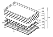
- FIG. 1 is an exploded perspective view showing a schematic configuration of the entire liquid crystal display device according to the embodiment.
- FIG. 2 is a partially enlarged view of the reflection sheet in the embodiment.
- FIG. 3 is a schematic diagram illustrating a positional relationship among the light source, the plurality of partition walls, and the luminance uniform plate in the embodiment.
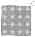
- FIG. 4 is a plan view of an example of a uniform luminance plate according to the embodiment.
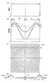
- FIG. 5 is a diagram illustrating an example of the unit pattern of the uniform luminance plate and the light transmittance within the unit pattern in the embodiment.
- FIG. 6 is a partially enlarged view of a reflective sheet in a modification of the embodiment.
- FIG. 1 is an exploded perspective view showing a schematic configuration of the entire liquid crystal display device according to the embodiment.
- the liquid crystal display device 10 includes a liquid crystal panel 11, a bezel 12, a backlight device 20 on a rectangular shape that is disposed on the back side of the liquid crystal panel 11 and has a size corresponding to the liquid crystal panel 11. Consists of.
- the liquid crystal panel 11 is a transmissive liquid crystal panel having a rectangular flat plate shape, and displays an image by transmitting or blocking light emitted from the backlight device 20 located on the back surface thereof.
- the bezel 12 is a casing on the front surface of the liquid crystal display device 10, and surrounds the liquid crystal panel 11 to protect the peripheral portion thereof.
- a plastic resin is mainly used from the viewpoints of design and lightness in the product.
- the backlight device 20 includes a plurality of printed boards 27 on which a plurality of light sources 21 are mounted, a chassis 22 that houses the plurality of printed boards 27, an optical unit 26 that is disposed between the liquid crystal panel 11 and the light sources 21, and a diffusion plate 25, a uniform luminance plate 24, and a reflection sheet 23.
- the printed circuit board 27 is supplied with electric power from a power source (not shown), and supplies this electric power to each light source 21 as driving electric power.
- the printed circuit board 27 in the present disclosure has a substantially rectangular shape, and six light sources 21 are mounted in a row along the longitudinal direction. According to FIG. 1, the plurality of printed circuit boards 27 are arranged in 7 rows ⁇ 2 columns in the chassis 22. As a result of this arrangement of the printed circuit board 27, the plurality of light sources 21 are arranged in a matrix. Note that the shape, size, number, and arrangement of the printed circuit boards 27 and the number of light sources 21 mounted on each printed circuit board 27 are not the gist of the present disclosure, and do not limit the present invention.
- the plurality of light sources 21 may be configured by using a plurality of types of light sources that emit monochromatic light such as red light, blue light, and green light, or may be configured only by light sources that emit white light. Also good. For example, an LED is used as such a light source 21.
- the chassis 22 is also a casing on the back surface of the liquid crystal display device 10.
- the chassis 22 is made of, for example, a plastic, a metal having a high-radiation ceramic sheet attached to the front or back, a metal anodized such as black, or a metal coated with carbon black.
- a metal anodized such as black
- a metal coated with carbon black As these metals, for example, alloys mainly composed of aluminum or iron are used.
- the reflection sheet 23 is a component made of a substantially flat resin, and its main surface is, for example, a mirror surface or white, and efficiently reflects light incident on the main surface.
- this main surface is also referred to as a reflective surface.
- This reflection surface is partitioned into a plurality of reflection regions 232 arranged in a matrix by a plurality of ridge-like partition walls 231 arranged in a lattice pattern.
- the saddle shape here means that the shape of the cross section perpendicular to the extending direction of the partition wall 231 has a width toward the top (in a direction opposite to the direction in which the chassis 22 is located) like a substantially triangular shape or a substantially trapezoidal shape. A shape that narrows.
- the vertical and horizontal pitches of the reflection areas 232 are the same as the vertical and horizontal pitches of the light sources 21 on the chassis 22.
- each light source 21 is arranged every 50 mm.
- Each reflection region 232 includes an opening 233 at substantially the center.
- FIG. 2 is a partially enlarged view of the state in which the reflection sheet 23 is superimposed on the chassis 22 in the present embodiment.
- the opening 233 is provided so that the light source 21 exits from the surface of the reflection sheet 23 in this state. Therefore, in the assembled liquid crystal display device 10, the light source 21 is disposed in each of the reflection regions 232.
- the reflection sheet 23 reflects the light emitted from each light source 21 in the direction of the luminance uniform plate 24.
- Such a reflection sheet 23 is produced by, for example, forming unevenness on a resin flat plate by vacuum forming.
- the bowl-shaped partition 231 has a height of 4.5 mm and is provided at a pitch of 50 mm. Further, processing such as drilling is performed as necessary.
- the luminance uniform plate 24 is a plate-shaped part made of a highly reflective and translucent resin (for example, polyethylene terephthalate).
- the uniform luminance plate 24 is arranged so that one main surface (hereinafter also referred to as a first surface) of the liquid crystal display device 10 in an assembled state faces the reflective surface of the reflective sheet 23 at a distance from the first surface.
- the light emitted from the light source 21 and the light reflected from the reflection sheet 23 are received. Then, the emitted light and the reflected light are transmitted, and emitted from the second surface, which is the main surface opposite to the first surface, as light with increased uniformity of luminance.
- the configuration of the luminance uniform plate 24 for emitting the light with enhanced luminance uniformity will be described later.
- Such a uniform brightness plate 24 is formed by molding the above-mentioned resin as a material, for example, by pressing.
- the diffuser plate 25 is a plate-like component having a refractive index higher than that of air, and is mainly made of, for example, an acrylic resin such as polymethyl methacrylate, polycarbonate, or the like, and a material containing fine particles dispersed throughout. Become. In the assembled liquid crystal display device 10, the diffusion plate 25 is positioned on the second surface side of the uniform luminance plate 24, and the light incident from the surface of the main surface facing the second surface of the uniform luminance plate 24 is the particle. And is emitted from the main surface opposite to the main surface.
- a diffusion plate 25 can be produced by, for example, injection molding the above-mentioned material.
- the optical unit 26 is located between the liquid crystal panel 11 and the diffusion plate 25 in the assembled liquid crystal display device 10 and faces the surface of the diffusion plate 25 from which light is emitted.
- the optical unit 26 has a size corresponding to the liquid crystal panel 11 and includes an optical sheet stack for further diffusing and collecting the light emitted from the diffusion plate 25.
- the optical sheet laminate includes, for example, a prism sheet that condenses incident light from the diffusion plate 25 toward a certain direction, a diffusion sheet that further diffuses incident light from the diffusion plate 25, and the diffusion plate 25.
- a polarizing sheet or the like that transmits light having a specific polarization plane corresponding to the polarization axis of the liquid crystal panel 11 is used.
- the brightness of the light emitted from the optical unit 26 is made uniform from the time of incidence, and the brightness uniformity of the backlight device 20 as the surface light source of the liquid crystal display device 10 is further increased.
- light derived from the light source 21 incident on the luminance uniform plate 24 from the first surface can be divided into the following three types having different paths.
- One is direct light from the light source 21.
- the other is reflected light that is reflected by the reflecting sheet 23 and is incident only once after being emitted from the light source 21.
- Another one is reflected light that is emitted from the light source 21 and then reflected m times on the reflection sheet 23 and n times on the luminance uniform plate 24 (m is an integer of 1 or more, and n is an integer of 1 or more).
- the sum of m and n is an integer of 2 or more).
- the incident light to the luminance uniform plate 24 composed of these three types of light is added in the region facing each reflection region 232, and the light is increased in luminance uniformity through the luminance uniform plate.
- the luminance uniform plate 24 increases the luminance uniformity
- FIG. 3 is a schematic diagram showing the positional relationship between the light source 21, the plurality of partition walls 231, and the luminance uniform plate 24 on one reflection region 232 of the backlight device 20 according to the present embodiment.
- (A) is sectional drawing of the reflective sheet 23 and the luminance uniform board 24,
- (b) is the top view which looked at the reflective sheet 23 from the luminance uniform board 24 side.
- a broken line is a boundary of the reflection region 232 surrounded by four partition walls 231 (here, these are distinguished, and reference numerals of the partition walls 231a to 231d are attached to indicate correspondence between (a) and (b)), And the boundary of the area
- Dotted arrows L1 to L6 indicate examples of light paths toward the first surface.
- the outline of the cross section of the partition wall 231 is a straight line, but the cross section of the partition wall 231 may be a straight line, a curve, or both.
- the partition wall 231 is drawn as a mountain-folded portion of the reflection sheet 23, but the partition wall 231 may be a hook-like protrusion on the reflection surface side of the reflection sheet 23, and the structure is not limited to the illustrated one.
- the incident light to the uniform luminance plate 24 attenuates according to the moving distance after emission from the light source 21, more specifically, in inverse proportion to the square of the moving distance.
- the direct light is attenuated according to the distance of the path from the light source 21 until reaching the first surface of the luminance uniform plate 24.
- the lengths of arrows L1 and L2 in (a) in this figure and arrows L5 and L6 in (b) indicate the travel distance of direct light from the light source 21, and incident light correlates with this travel distance. It is decaying. That is, the incident light that is further from the light source 21 and enters the luminance uniform plate 24 is more attenuated.
- the reflection sheet 23 includes the partition wall 231 protruding toward the luminance uniform plate 24 side, and therefore the distance between the reflection surface and the first surface varies depending on the location (for example, arrows L3 and L4). ). Therefore, similarly to the direct light, the degree of attenuation of the reflected light varies depending on the incident location.
- the intensity of the reflected light incident on the uniform luminance plate 24 correlates not only with the moving distance as described above but also with the number of times reflected by the reflective sheet 23 and the uniform luminance plate 24 before incidence. More precisely, the reflected light is weakened in correlation with the m-th power of the reflectance of the reflection sheet 23 and the n-th power of the luminance uniform plate 24 (m and n are as described above) in addition to the moving distance.
- the light emitted from the light source 21 has some attenuation factors before entering the luminance uniform plate 24, and the degree of attenuation is uniform luminance facing one reflection region 232.
- the degree of attenuation is uniform luminance facing one reflection region 232.
- the region facing the partition wall 231 and the other region arrows L3 and L4.
- the distance from the reflecting surface is also different in the region facing the partition wall 231.
- the reflected light that is reflected at the highest part of the partition wall 231 hereinafter also referred to as the top of the partition wall 231 and enters the region facing this part has the smallest attenuation rate due to the moving distance.
- the intensity of the incident light composed of such direct light and reflected light in the entire area of the uniform luminance plate 24 facing one reflection area 232 is, for example, the strongest in the area facing the light source 21 and as the distance from the light source 21 increases.
- the distribution is such that the distance from the light source 21 increases, that is, the region becomes stronger as it approaches the top.
- the incident light in the region where the luminance uniform plate 24 faces the top of the partition wall 231 is weaker than the region facing the light source 21.
- the transmittance with respect to the incident light (hereinafter also simply referred to as light transmittance) in each region facing the reflection region 232 of the luminance uniform plate 24 is changed in a predetermined pattern to change the inside of the region.
- the uniformity of the brightness of the light emitted from the second surface is increased.
- the predetermined pattern is that the distribution of light transmittance of the luminance uniform plate 24 in the region facing each reflection region 232 of the luminance uniform plate 24 is the intensity of incident light to the luminance uniform plate 24. It has a negative correlation.
- the product of the intensity of incident light and the light transmittance at each location is brought close to a constant, and the uniformity of the brightness of the light emitted from the brightness uniform plate 24 is increased.
- the contrast between the bright part and the dark part in the screen corresponding to the image displayed on the entire screen is increased.
- the configuration of the uniform brightness plate 24 that realizes the predetermined pattern will be described by taking as an example the case where the intensity of incident light on the uniform brightness plate 24 exhibits the above-described distribution.
- FIG. 4 is a plan view (part) of an example of the uniform luminance plate 24 in the present embodiment.
- a large number of circles seen in this figure indicate through-holes 241 penetrating between the first surface and the second surface of the luminance uniform plate 24. That is, the uniform luminance plate 24 shown in the figure has a plurality of through holes 241 penetrating between the first surface and the second surface.
- the through hole 241 in this example has variations in size (opening area of each through hole). These through holes 241 having different sizes are arranged so as to form one pattern in the entire region facing one reflection region 232 of the luminance uniform plate 24, and this pattern is repeated vertically and horizontally over the entire luminance uniform plate 24. It is.
- the plurality of through holes 241 arranged so as to form such a single pattern are, for example, a plurality of protrusions that penetrate the flat plate of the resin material in one step of press processing for forming the above-described luminance uniform plate 24. It is provided using the type
- the predetermined pattern of the light transmittance described above is realized by a pattern (hereinafter referred to as a unit pattern) over the entire region facing this one reflection region 232.
- this unit pattern will be described.
- FIG. 5 is a diagram showing an example of the unit pattern of the uniform luminance plate 24 and the light transmittance within the unit pattern in the present embodiment.
- This unit pattern is shown in (c) of this figure, and (b) shows the light transmittance on line A and the light transmittance on line B of the luminance uniform plate 24 having this unit pattern.
- It is a graph.
- (D) of this figure is sectional drawing which shows the cut surface obtained by cut
- (A) is a graph which shows the intensity
- the horizontal axes of the graphs of (a) and (b) correspond to the horizontal position of the unit pattern shown in (c) and the horizontal position of the reflection sheet 23 shown in (d).
- the light transmittance used in the description of the unit pattern means the light transmittance per unit area.
- the light transmittance indicated by this graph is the same as that of the incident light on the first surface passing through the through hole 241 and the light emitted from the opening on the second surface side and the resin within the unit area. It is a total ratio with the light which appeared on the 2nd surface side.
- region which has a unit area in this indication shall not be settled in opening of arbitrary through-holes 241.
- the material of the uniform brightness plate 24 has translucency, but is not transparent. More specifically, the luminance uniform plate 24 is a resinous white plate having a through hole 241. Therefore, the uniform luminance plate 24 transmits light to some extent even in an arbitrary region that does not include the through hole 241.
- the range in which the light transmittance near the center of the graph corresponding to the line A is constant corresponds to a region near the center in the diagram (c) where there is no through hole 241. The reason why the light transmittance is not zero in this range is due to the translucency of the material of the uniform luminance plate 24 itself.
- the through holes 241 allow light to pass from the first surface side to the second surface side of the luminance uniform plate 24 at a higher rate (substantially 100%) than the resin that is the material of the luminance uniform plate 24. Therefore, in the region of the unit area, the light transmittance of this region increases as the opening area of the through hole 241 increases. In other words, the opening area of the through hole 241 per unit area of the luminance uniform plate 24 and the light transmittance have a positive correlation. Then, by changing the opening area per unit area (hereinafter also referred to as the aperture ratio) depending on the location, the light transmittance in the region of the luminance uniform plate 24 facing one reflection region 232 is changed.
- the aperture ratio the opening area per unit area
- the light transmittance is increased by increasing the aperture ratio, and the light transmittance is decreased by decreasing the aperture ratio.
- the pitch between the through holes 241 is uniform in the region where the through holes 241 exist, and the aperture ratio is changed by changing the size of each through hole 241. As a result, the light transmittance is changed.
- the intensity of the incident light in the region of the luminance uniform plate 24 facing one reflection region 232 is the strongest in the region facing the light source 21 as described above, and decreases as the distance from the light source 21 increases. In the region facing the partition wall 231, it becomes stronger as it approaches the top. That is, in the region of the brightness uniform plate 24 that does not face the partition wall 231, the intensity of incident light and the distance from the light source 21 have a negative correlation.
- the product of the intensity of incident light and the light transmittance in this region approaches a constant between the distance from the light source 21 and the light transmittance of the uniform luminance plate 24. Have a positive correlation.
- the luminance of the emitted light from the second surface of the uniform luminance plate 24 in this region is brought close to a constant state regardless of the distance from the light source 21 as shown in FIG. Can do.
- the aperture area per unit area of the luminance uniform plate 24 and the distance from the light source 21 have a positive correlation.
- a hole 241 is provided in the luminance uniform plate 24. This region substantially corresponds to the range indicated by III and IV in FIG.
- FIG. 5B there is a difference between the light transmittance on the line A and the light transmittance on the line B even at the same left and right positions. This reflects the difference in the degree of attenuation.
- the through-hole 241 is not provided as shown in the figure in the region facing the light source 21 and in the vicinity thereof. This region substantially corresponds to the range indicated by IV in FIG.
- the region where the through-holes 241 are not provided as described above is appropriately determined according to, for example, the light distribution of the light source 21 and the degree of diffusion of incident light (scattering in the luminance uniform plate 24) by the luminance uniform plate 24.
- the intensity of incident light and the distance from the partition wall 231 have a negative correlation.
- the backlight device 20 in the present embodiment has a relationship between the intensity of incident light and the light transmittance in this area. A positive correlation is given so that the product approaches a constant value. As a result, the brightness of the emitted light from the second surface of the uniform brightness plate 24 in this region can be brought close to a constant state regardless of the distance from the top as shown in FIG. it can.
- the opening area per unit area of the luminance uniform plate 24 and the distance from the top of the partition 231 have a positive correlation in the region facing the partition 231 of the luminance uniform plate 24.
- a through-hole 241 is provided in the luminance uniform plate 24 so that there is a region. This region substantially corresponds to the range indicated by I and II in FIG.
- the distribution of the light transmittance of the luminance uniform plate 24 provided with the through-holes 241 as described above will be described with reference to the entire region of the luminance uniform plate 24 facing one reflection region 232.
- a region having a higher light transmittance than any of these regions is between the region facing the light source 21 and the region facing the top of the partition wall 231. If this region is shown more specifically, it can be said that the luminance uniform plate 24 is in the vicinity of the boundary between the region facing the partition wall 231 and the other region. In FIG. 5B, this region is a region near the peak of each curve, which is near the boundary between the range indicated by II and the range indicated by III. Further, the light transmittance has a minimum value in a region facing the light source 21.
- This region is included in the range indicated by IV in FIG.
- the maximum value is found between the region facing the light source 21 and the region facing the top of the partition wall 231.
- the opening area of one through-hole 241 inside the region of the luminance uniform plate 24 not facing the partition wall 231 and in the vicinity of the corner is the highest (that is, the light transmittance is high). ).
- the boundaries of these areas are not strictly determined based on these positional relationships. It may vary to some extent due to light scattering by the reflection surface of the reflection sheet 23, diffusion of incident light by the luminance uniform plate 24 (scattering in the luminance uniform plate 24), and the like. For this reason, in the design of the uniform luminance plate 24, it is necessary to appropriately adjust the light transmittance distribution in consideration of the influence of these variable factors.
- the through holes 241 are arranged at an equal pitch, and the aperture ratio is changed by changing the size of each through hole 241, but the luminance uniform plate 24 in the present invention.
- the configuration is not limited to this. Any configuration may be used as long as the light transmittance distribution in the unit pattern of the luminance uniform plate 24 as described above can be obtained.
- the opening area of the plurality of through holes 241 may be the same, and the opening ratio may be changed by changing the number of through holes 241 per unit area, that is, the density of the through holes 241.
- the opening area of each through-hole 241 in a region not facing the partition wall 231 has a positive correlation with the distance from the light source 21, but the opening for each through-hole 241. If there is a variation in area, this correlation may be absent. In other words, a positive correlation may be established between the distance from the light source 21 and the aperture ratio, and the aperture ratio may be satisfied by the plurality of through holes 241. For example, depending on the location, the through hole 241 having a larger opening area may be provided so as to surround the through hole 241 having a smaller opening area. Alternatively, the through hole 241 having a smaller opening area may be provided so as to surround the through hole 241 having a larger opening area.
- the arrangement of the through holes 241 is not limited to the example of the unit pattern shown in FIG.
- FIG. Moreover, you may arrange
- the shape of the through hole 241 is not limited to a circle as shown in FIGS. Moreover, the shape of all the through-holes 241 may not be congruent or similar. That is, there may be variations in the shape of the through hole 241.
- a negative correlation may be given between the light transmittance of the uniform luminance plate 24 and the intensity of light received by the uniform luminance plate 24 on the first surface.
- the light transmittance of the luminance uniform plate 24 may be changed by applying a light shielding agent such as a paint having a light shielding property to the luminance uniform plate 24 in a predetermined pattern.
- the light transmittance of the uniform luminance plate 24 may be changed by applying the light shielding agent while changing the application area per unit area of the uniform luminance plate 24. In this case, for example, it is realized by applying paint so as to draw dots having different areas depending on the location, or changing the density of dots drawn by the paint.
- the concentration of the paint may be changed depending on the place, or paints having different light transmittances may be used.
- a non-through hole may be used instead of the through hole 241. That is, the light transmittance of the uniform luminance plate 24 may be changed by changing the average thickness per unit area of the uniform luminance plate 24. The configuration not including these through holes is also applied so that the light transmittance distribution of the uniform luminance plate 24 has the same characteristics as described above.
- the through hole 241 and the above-described light shielding agent or non-through hole may be used in combination.
- FIG. 6 is a partially enlarged view of a reflective sheet 23a according to a modification of the above embodiment.
- the reflective sheet 23 a is different from the reflective sheet 23 in that the reflective sheet 23 a has support pillars 234 that protrude toward the uniform brightness plate 24 on the partition wall 231 that projects in the direction in which the uniform brightness plate 24 exists.
- the support column 234 supports the luminance uniform plate 24 in a state where the tip is inserted into the hole of the luminance uniform plate 24.
- the uniform brightness plate 24 is prevented from being bent by its own weight.
- the larger luminance uniform plate 24 is used in accordance with the display surface.
- an increase in the size of the uniform luminance plate 24 causes a deflection due to its own weight. If the thickness of the luminance uniform plate 24 is increased in order not to cause this deflection, a decrease in the light transmittance due to the increase in the thickness may result in insufficient luminance of the emitted light to the diffusion plate, or to avoid this insufficient luminance.
- the uniform luminance plate 24 There is an influence such as a change in specifications of the uniform luminance plate 24 or other components. As described above, it is not preferable to increase the thickness of the uniform luminance plate 24 in order to prevent the deflection. Further, even when the liquid crystal display device 10 is relatively small, the uniform brightness plate 24 is easily bent by providing the plurality of through holes 241 as in the present disclosure. The bent uniform brightness plate 24 cannot obtain an appropriate positional relationship between the light source 21 and the partition wall 231 in each reflection region 232 as described above, and therefore cannot increase the brightness uniformity.
- the support pillar 234 described above may be provided.
- positioning of the support pillar 234 shown by FIG. 6 are examples, and are not limited to this.
- only one of the support pillars 234 that protrude from the center of the reflection sheet 23 a and fit into a hole in the center of the luminance uniform plate 24 may be provided.
- it may be arranged at a position where the partition walls 231 arranged in a lattice shape intersect, or may be arranged at other positions as shown in the figure.
- the hole of the luminance uniform plate 24 into which the tip of the support column 234 is inserted is provided separately from the hole for giving the luminance uniform plate 24 a predetermined light transmittance distribution pattern.
- a support column 234 is formed by processing a highly reflective material such as polycarbonate by injection molding or the like. The material may be the same as or different from that of the reflection sheet 23a. Moreover, it may be molded integrally with the reflection sheet 23a, or may be prepared separately from the reflection sheet 23a and attached to the reflection sheet 23a.
- a support column 234 affects the intensity of light reaching the first surface of the luminance uniform plate 24 due to a difference in material from the reflection sheet 23 a or a difference in shape from the surrounding partition wall 231. Under this influence, the light reaching the first surface around the support pillar 234 may become stronger or weaker. That is, it causes unevenness in the intensity of light incident on the luminance uniform plate 24.
- the uniform brightness plate 24 may have a light transmittance distribution pattern that suppresses unevenness of light intensity caused by the support pillars 234.
- the luminance uniform plate 24 supported by the support pillar 234 is a positive region between the opening area per unit area and the distance from the top of the partition wall around the support pillar 234 in the region facing the plurality of partition walls.
- Each light source 21 is controlled to be turned on or off independently.
- the light emitted from the light source 21 becomes direct light, and the light reflected by the reflection sheet 23 after being reflected by the reflection sheet 23 or the luminance uniform plate 24 is reflected light. Is incident on the uniform luminance plate 24.
- interference of light emitted from the light source 21 in each reflection region 232 to the surrounding reflection region 232 is caused by the hook-shaped partition wall 231 provided around each light source 21 and projecting toward the luminance uniform plate 24. Is suppressed.
- the brightness uniform plate 24 emits light with a higher degree of brightness uniformity.
- the light emitted from the uniform luminance plate 24 enters the diffusion plate 25.
- the incident light to the uniform brightness plate 24 is attenuated according to the moving distance from the light source 21 and the number of reflections, and the intensity varies depending on the location.
- the light transmittance distribution of the uniform luminance plate 24 is negatively correlated with such unevenness in the intensity of incident light.
- the light transmittance per unit area is changed depending on the place. More specifically, large through holes 241 are provided or the through holes 241 are provided at high density so that the aperture ratio is relatively large in a region where incident light is relatively strong. This is, for example, a region that does not face the partition wall 231 and that is away from the light source 21.
- the through hole 241 is provided so that the aperture ratio is relatively small at a place where the distance from the partition wall 231 is relatively short, and the aperture ratio is relatively large at a place where this distance is long.
- the through hole 241 is not provided in the region that faces the light source 21 and receives strong direct light. Thereby, the difference in intensity depending on the location of the incident light on the luminance uniform plate 24 is absorbed, and the uniformity of the luminance of the outgoing light to the diffusion plate 25 can be increased.
- the intensity of light incident on the luminance uniform plate 24 is uneven due to the light reflection characteristics of the support column 234.
- the unevenness of the intensity of light is also absorbed by changing the light transmittance per unit area of the luminance uniform plate 24 around the support column 234, for example, around the support column 234, and thereby the luminance uniform plate 24.
- the uniformity of the emitted light can be increased.
- the diffusion plate 25 diffuses the light with the increased brightness uniformity in this way, and emits the light with a higher uniformity.
- the light emitted from the diffusing plate 25 is further diffused and condensed by the optical unit 26 and irradiated onto the liquid crystal panel 11.
- the backlight device is disposed in each of the reflection sheet having a reflection surface partitioned into a plurality of reflection regions by a plurality of bowl-shaped partition walls and the plurality of reflection regions of the reflection surface.
- a plurality of light sources to be transmitted, and light emitted from the plurality of light sources received by the first surface facing the reflection surface and reflected light from the reflection sheet are transmitted, and the second light beam is opposite to the first surface.
- a backlight device comprising a uniform luminance plate that emits from a surface and a diffuser plate that diffuses and emits light emitted from the second surface, wherein the uniform luminance plate is a region facing the light source; Between the area
- the luminance uniform plate 24 has a light transmittance distribution having a negative correlation with the intensity of incident light that varies depending on the location, and increases the uniformity of the luminance of the emitted light.
- the uniform luminance plate has a plurality of through holes penetrating between the first surface and the second surface, and the opening area of the through hole per unit area of the uniform luminance plate and the light
- the transmittance may have a positive correlation.
- the light transmittance increases in a region including the opening. Further, by changing the opening area per unit area, the light transmittance of the region including the opening can be changed. Thereby, the light transmittance distribution as described above can be given to the luminance uniform plate 24. That is, the uniformity of the brightness of light emitted from the brightness uniform plate 24 to the diffusion plate 25 can be increased.
- the opening area per unit area and the distance from the top of the partition may have a positive correlation.
- the light transmittance of the uniform luminance plate 24 is suppressed in a region that receives reflected light with a small attenuation due to distance among light reflected by the reflection sheet 23, and is increased in a region that receives reflected light with a large attenuation due to distance. Can do.
- the uniformity of the luminance of the light emitted from the luminance uniform plate 24 to the diffusion plate 25 can be increased.
- the opening area per unit area and the distance from the light source may have a positive correlation. That is, the light transmittance of the uniform luminance plate 24 may be suppressed in a region that receives direct light with a small attenuation due to distance among light emitted from the light source 21, and may be increased in a region that receives direct light with a large attenuation due to distance. it can. Thereby, the uniformity of the luminance of the light emitted from the luminance uniform plate 24 to the diffusion plate 25 can be increased.
- the light transmittance per unit area in the region of the luminance uniform plate facing the reflection region takes a minimum value in the region facing the light source, the region facing the light source, and the top of the partition wall A maximum value may be taken between the regions facing each other. That is, the light transmittance of the uniform luminance plate 24 is the lowest in the region receiving the strongest light in the region facing the reflection region 232. Further, in this region, the light transmittance is highest in a region that receives direct light attenuated compared to the light received by the region receiving the strongest light and also has a large attenuation of the reflected light received from the reflection sheet 23. Thereby, the uniformity of the luminance of the light emitted from the luminance uniform plate 24 to the diffusion plate 25 can be increased.
- the reflection sheet further includes a support column that protrudes toward the luminance uniform plate on the plurality of partition walls and supports the luminance uniform plate, and the reflection sheet includes a support column in a region facing the plurality of partition walls.
- the opening area per unit area and the distance from the top of the partition do not have a positive correlation.
- a liquid crystal display device includes a liquid crystal panel, and any one of the backlight devices disposed on the back side of the liquid crystal panel and corresponding to the liquid crystal panel. This provides a liquid crystal display device that provides high-contrast expression over the entire screen by area control and that has a high degree of luminance uniformity within the area of the unit of luminance control.
- the shape and size of each component and the ratio of sizes between components are examples, and the present invention is not limited to this.
- the slope of the partition wall 231 may be gentler or steep.
- the slope of the partition wall 231 may vary depending on the location in the reflection region 232.
- the slope of the partition wall 231 is gentle at the four corners of the reflection region 232 in plan view, and may be closer to the light source 21 than shown in FIGS.
- the correlation between the aperture ratio of the uniform luminance plate 24 and the distance from the top of the partition wall 231 or the light source 21 is as described above.
- the method of creating each component is not limited to the one described in the embodiment.
- the uniform brightness plate 24 may be formed by injection molding a resin as a material.
- various processing methods applicable as necessary may be used.
- the through-hole 241 of the uniform luminance plate 24 may be provided by punching in press working, or may be provided by drilling using a drill, a laser, or the like.
- the present disclosure can be applied to a backlight device and a liquid crystal display device including the backlight device in general.
Abstract
This backlight device (20) is provided with: a reflective sheet (23) which includes a reflective surface partitioned into a plurality of reflective regions (232) by a plurality of ridge-shaped partitioning walls (231); a plurality of light sources (21) which are respectively disposed in the plurality of reflective regions (232); a luminance-uniformity plate (24) through which light incident on a first surface thereof opposed to the reflective surface is allowed to transmit and which emits the light from a second surface thereof; and a diffusing plate (25) which diffuses and emits the light having been emitted from the second surface and having entered the diffusing plate (25), wherein the luminance-uniformity plate (24) includes, between a region opposed to each of the light sources (21) and a region opposed to the top section of a corresponding one of the partitioning walls (231), a region having a higher light transmittance per unit area than the region opposed to the light source (21) or the region opposed to the top section the partitioning wall (231).
Description
本開示は、複数の光源を含むバックライト装置と、当該バックライト装置を備えた液晶表示装置とに関する。
The present disclosure relates to a backlight device including a plurality of light sources and a liquid crystal display device including the backlight device.
液晶表示装置は薄型、低消費電力、高精細などの特徴を有し、製造技術の発達による画面サイズの大型化も伴い、テレビジョン受信機分野への普及が進行している。しかしながら液晶表示装置では、その表示方法に起因する、表示される画像のコントラスト(ダイナミックレンジ)の低さが指摘されている。そのため、近年は表示画像の画質向上に関する技術開発が盛んになされている。
Liquid crystal display devices have features such as thinness, low power consumption, and high definition, and with the increase in screen size due to the development of manufacturing technology, they are spreading to the field of television receivers. However, in the liquid crystal display device, it is pointed out that the contrast (dynamic range) of the displayed image is low due to the display method. For this reason, in recent years, technological development relating to the improvement of image quality of display images has been actively performed.
テレビジョン受信機に用いられる液晶表示装置は、その表示面全体を背面側から照らすバックライト装置を備える。このバックライト装置の光源としては、粒状の発光ダイオード(light-emitting diode、以下ではLEDと表記する)を液晶パネルの裏側に複数並べたものが用いられる。そしてこの複数の光源で照らされる領域全体で均一な輝度を得るために、液晶パネルが設置される側とは反対側に光反射シートが設けられたり、液晶パネルとこれらの光源との間に光拡散板が設けられたりする。また、反射シート上に格子状の隔壁を設けて複数の反射領域に分割し、各反射領域に上記の光源を設けて、各光源による反射領域間での干渉を隔壁で抑えながらこれらの反射領域単位での輝度制御(エリア制御、又はローカルディミングともいわれる)を可能にしている(特許文献1参照)。これにより、例えば画面内で明るい部分と暗い部分とに分かれるようなシーンを表示する際に、これらの部分間のコントラストが高まるように、各部分での明るさに応じて反射領域単位で輝度が制御される。
A liquid crystal display device used in a television receiver includes a backlight device that illuminates the entire display surface from the back side. As a light source of the backlight device, a plurality of granular light-emitting diodes (light-emitting diodes, hereinafter referred to as LEDs) arranged on the back side of the liquid crystal panel is used. In order to obtain uniform brightness over the entire area illuminated by the plurality of light sources, a light reflecting sheet is provided on the side opposite to the side on which the liquid crystal panel is installed, or light is provided between the liquid crystal panel and these light sources. A diffusion plate is provided. In addition, a grid-like partition wall is provided on the reflection sheet to divide it into a plurality of reflection areas, and each of the reflection areas is provided with the above-described light source. Luminance control in units (also referred to as area control or local dimming) is enabled (see Patent Document 1). As a result, for example, when displaying a scene that is divided into a bright part and a dark part on the screen, the brightness in units of reflective areas is increased according to the brightness of each part so that the contrast between these parts is increased. Be controlled.
従来の液晶表示装置では、各反射領域内での輝度の均一度への隔壁による影響の抑制が不十分であり、各反射領域内で輝度ムラを生じる。その結果、バックライト装置全体では画面内の明るい部分と暗い部分とのコントラストが十分に高められないという問題がある。
In the conventional liquid crystal display device, the influence of the partition walls on the luminance uniformity in each reflection area is not sufficiently suppressed, and uneven brightness occurs in each reflection area. As a result, there is a problem that the contrast between the bright part and the dark part in the screen cannot be sufficiently increased in the entire backlight device.
本開示は、このような輝度ムラをさらに抑制し、画面全体でのより高いコントラストの表現が可能な液晶表示装置を提供する。
The present disclosure provides a liquid crystal display device that can further suppress such luminance unevenness and can express higher contrast on the entire screen.
本開示に係るバックライト装置は、複数の畝状の隔壁で複数の反射領域に区画された反射面を有する反射シートと、前記反射面の前記複数の反射領域のそれぞれに配置される複数の光源と、前記反射面に対向する第1面で受けた前記複数の光源からの出射光及び前記反射シートからの反射光を透過させて、前記第1面と反対側の第2面から出射する輝度均一板と、前記第2面から出射した光を、拡散して出射する拡散板とを備えるバックライト装置であって、前記輝度均一板は、前記光源に対向する領域と、前記隔壁の頂部に対向する領域との間に、前記光源と対向する領域及び隔壁の頂部に対向する領域よりも単位面積あたりの光透過率が高い領域を含む。
A backlight device according to the present disclosure includes a reflection sheet having a reflection surface partitioned into a plurality of reflection regions by a plurality of bowl-shaped partition walls, and a plurality of light sources disposed in each of the plurality of reflection regions of the reflection surface And the luminance that is transmitted from the plurality of light sources received by the first surface opposite to the reflection surface and the reflection light from the reflection sheet and is emitted from the second surface opposite to the first surface A backlight device comprising a uniform plate and a diffuser plate that diffuses and emits light emitted from the second surface, wherein the uniform luminance plate is located at a region facing the light source and at the top of the partition wall. A region having a higher light transmittance per unit area than a region facing the light source and a region facing the top of the partition is included between the facing regions.
また、本開示に係る液晶表示装置は、液晶パネルと、前記液晶パネルに対応する上記のバックライト装置とを備える。
Further, a liquid crystal display device according to the present disclosure includes a liquid crystal panel and the backlight device corresponding to the liquid crystal panel.
本開示に係るバックライト装置は出射光の輝度ムラが抑制され、画面全体でのより高いコントラストの表現が可能な液晶表示装置の実現に有効である。
The backlight device according to the present disclosure is effective in realizing a liquid crystal display device that can suppress uneven brightness of emitted light and can express higher contrast on the entire screen.
以下、適宜図面を参照しながら、実施の形態を詳細に説明する。ただし、必要以上に詳細な説明は省略する場合がある。例えば、既によく知られた事項の詳細説明や実質的に同一の構成に対する重複説明を省略する場合がある。これは、以下の説明が不必要に冗長になるのを避け、当業者の理解を容易にするためである。
Hereinafter, embodiments will be described in detail with reference to the drawings as appropriate. However, more detailed explanation than necessary may be omitted. For example, detailed descriptions of already well-known matters and repeated descriptions for substantially the same configuration may be omitted. This is to avoid the following description from becoming unnecessarily redundant and to facilitate understanding by those skilled in the art.
なお、当業者が本開示を十分に理解するために添付図面および以下の説明を提供するのであって、これらによって請求の範囲に記載の主題を限定することを意図するものではない。
It is to be noted that those skilled in the art provide the accompanying drawings and the following description in order to fully understand the present disclosure, and are not intended to limit the claimed subject matter.
(実施の形態)
以下、図1~5を用いて、実施の形態を説明する。 (Embodiment)
The embodiment will be described below with reference to FIGS.
以下、図1~5を用いて、実施の形態を説明する。 (Embodiment)
The embodiment will be described below with reference to FIGS.
図1は、実施の形態における液晶表示装置全体の概略構成を示す分解斜視図である。
FIG. 1 is an exploded perspective view showing a schematic configuration of the entire liquid crystal display device according to the embodiment.
[1-1.構成]
[1-1-1.液晶表示装置の構成]
図1に示すように、液晶表示装置10は、液晶パネル11と、ベゼル12と、液晶パネル11の背面側に配置され、液晶パネル11に対応する大きさの直方形上のバックライト装置20とからなる。 [1-1. Constitution]
[1-1-1. Configuration of liquid crystal display device]
As shown in FIG. 1, the liquidcrystal display device 10 includes a liquid crystal panel 11, a bezel 12, a backlight device 20 on a rectangular shape that is disposed on the back side of the liquid crystal panel 11 and has a size corresponding to the liquid crystal panel 11. Consists of.
[1-1-1.液晶表示装置の構成]
図1に示すように、液晶表示装置10は、液晶パネル11と、ベゼル12と、液晶パネル11の背面側に配置され、液晶パネル11に対応する大きさの直方形上のバックライト装置20とからなる。 [1-1. Constitution]
[1-1-1. Configuration of liquid crystal display device]
As shown in FIG. 1, the liquid
液晶パネル11は長方形の平板形状を有する透過型の液晶パネルであり、その背面に位置するバックライト装置20から出射された光を透過又は遮断することで画像を表示する。
The liquid crystal panel 11 is a transmissive liquid crystal panel having a rectangular flat plate shape, and displays an image by transmitting or blocking light emitted from the backlight device 20 located on the back surface thereof.
ベゼル12は、液晶表示装置10の前面のケーシングであり、液晶パネル11を囲繞してその周縁部分を保護する。ベゼル12の材料としては、製品におけるデザイン性や軽量性などの観点から、主にプラスチック樹脂が使用される。
The bezel 12 is a casing on the front surface of the liquid crystal display device 10, and surrounds the liquid crystal panel 11 to protect the peripheral portion thereof. As a material of the bezel 12, a plastic resin is mainly used from the viewpoints of design and lightness in the product.
[1-1-2.バックライト装置の構成]
バックライト装置20は、複数の光源21が実装された複数のプリント基板27、複数のプリント基板27を収容するシャーシ22、液晶パネル11と光源21との間に配置される光学部26、拡散板25、輝度均一板24、及び反射シート23を備える。 [1-1-2. Configuration of backlight device]
Thebacklight device 20 includes a plurality of printed boards 27 on which a plurality of light sources 21 are mounted, a chassis 22 that houses the plurality of printed boards 27, an optical unit 26 that is disposed between the liquid crystal panel 11 and the light sources 21, and a diffusion plate 25, a uniform luminance plate 24, and a reflection sheet 23.
バックライト装置20は、複数の光源21が実装された複数のプリント基板27、複数のプリント基板27を収容するシャーシ22、液晶パネル11と光源21との間に配置される光学部26、拡散板25、輝度均一板24、及び反射シート23を備える。 [1-1-2. Configuration of backlight device]
The
プリント基板27は、図示しない電源から電力の供給を受け、この電力を各光源21に駆動電力として供給する。本開示におけるプリント基板27は略矩形の形状を有し、長手方向に沿って6個の光源21を一列に実装している。図1によれば、複数のプリント基板27はシャーシ22内に7行×2列に配置されている。プリント基板27のこの配置の結果、複数の光源21はマトリクス状に配置されている。なお、プリント基板27の形状、大きさ、枚数、配置、及び各プリント基板27に実装される光源21の数は本開示の要旨ではなく、本発明を限定するものではない。
The printed circuit board 27 is supplied with electric power from a power source (not shown), and supplies this electric power to each light source 21 as driving electric power. The printed circuit board 27 in the present disclosure has a substantially rectangular shape, and six light sources 21 are mounted in a row along the longitudinal direction. According to FIG. 1, the plurality of printed circuit boards 27 are arranged in 7 rows × 2 columns in the chassis 22. As a result of this arrangement of the printed circuit board 27, the plurality of light sources 21 are arranged in a matrix. Note that the shape, size, number, and arrangement of the printed circuit boards 27 and the number of light sources 21 mounted on each printed circuit board 27 are not the gist of the present disclosure, and do not limit the present invention.
複数の光源21は、それぞれが赤色光、青色光、緑色光などの単色の光を発光する光源を複数種類用いて構成されてもよいし、または、白色光を発光する光源のみで構成されてもよい。例えばLEDがこのような光源21として用いられる。
The plurality of light sources 21 may be configured by using a plurality of types of light sources that emit monochromatic light such as red light, blue light, and green light, or may be configured only by light sources that emit white light. Also good. For example, an LED is used as such a light source 21.
シャーシ22は、液晶表示装置10の背面のケーシングでもある。シャーシ22は、例えばプラスチック、表裏に高放射性セラミックスシートが貼付された金属、又は黒色などのアルマイト処理された金属や、カーボンブラックを塗布した金属を材料とする部品で構成される。これらの金属としては、例えばアルミニウムや鉄などを主成分とした合金などが用いられる。
The chassis 22 is also a casing on the back surface of the liquid crystal display device 10. The chassis 22 is made of, for example, a plastic, a metal having a high-radiation ceramic sheet attached to the front or back, a metal anodized such as black, or a metal coated with carbon black. As these metals, for example, alloys mainly composed of aluminum or iron are used.
反射シート23は略平板形状の樹脂からなる部品であり、その主面は例えば鏡面、白色等で、この主面に落射する光を効率よく反射する。以下、この主面を反射面ともいう。この反射面は、格子状に並ぶ、複数の畝状の隔壁231によって、マトリクス状に並ぶ複数の反射領域232に区画される。ここでいう畝状とは、隔壁231の延伸方向に垂直な断面の形状が、略三角形若しくは略台形のように、頂部に向かって(シャーシ22がある方向と反対の方向に向かって)幅が狭くなる形状を指す。
The reflection sheet 23 is a component made of a substantially flat resin, and its main surface is, for example, a mirror surface or white, and efficiently reflects light incident on the main surface. Hereinafter, this main surface is also referred to as a reflective surface. This reflection surface is partitioned into a plurality of reflection regions 232 arranged in a matrix by a plurality of ridge-like partition walls 231 arranged in a lattice pattern. The saddle shape here means that the shape of the cross section perpendicular to the extending direction of the partition wall 231 has a width toward the top (in a direction opposite to the direction in which the chassis 22 is located) like a substantially triangular shape or a substantially trapezoidal shape. A shape that narrows.
各反射領域232の縦横のピッチはシャーシ22上にある光源21の縦横のピッチとそれぞれ共通である。例えば反射領域232の縦横のピッチをいずれも50mmとすると、各光源21は50mmごとに配置される。また、各反射領域232は略中央に開口部233を備える。図2は、本実施の形態におけるシャーシ22の上に反射シート23を重ねた状態の部分拡大図である。開口部233は、この状態で光源21が反射シート23の表面に出るよう設けられる。したがって、組立状態の液晶表示装置10では、光源21は反射領域232のそれぞれに配置される。そして反射シート23は、各光源21から出射された光を輝度均一板24の方向に反射する。このような反射シート23は、例えば樹脂の平板に真空成形によって凹凸を付けて作成される。例えば畝状の隔壁231は、高さ4.5mmで、50mmのピッチで設けられる。また、必要に応じて孔開け等の加工が施される。
The vertical and horizontal pitches of the reflection areas 232 are the same as the vertical and horizontal pitches of the light sources 21 on the chassis 22. For example, if the vertical and horizontal pitches of the reflection regions 232 are both 50 mm, each light source 21 is arranged every 50 mm. Each reflection region 232 includes an opening 233 at substantially the center. FIG. 2 is a partially enlarged view of the state in which the reflection sheet 23 is superimposed on the chassis 22 in the present embodiment. The opening 233 is provided so that the light source 21 exits from the surface of the reflection sheet 23 in this state. Therefore, in the assembled liquid crystal display device 10, the light source 21 is disposed in each of the reflection regions 232. The reflection sheet 23 reflects the light emitted from each light source 21 in the direction of the luminance uniform plate 24. Such a reflection sheet 23 is produced by, for example, forming unevenness on a resin flat plate by vacuum forming. For example, the bowl-shaped partition 231 has a height of 4.5 mm and is provided at a pitch of 50 mm. Further, processing such as drilling is performed as necessary.
輝度均一板24は、高反射性であって透光性も有する樹脂(例えばポリエチレンテレフタラート)を材料とする板状体の部品である。輝度均一板24は、組立状態の液晶表示装置10において一方の主面(以下、第1面ともいう)が反射シート23の反射面と距離を置いて対向するよう配置され、この第1面で光源21からの出射光と反射シート23からの反射光を受ける。そしてこれらの出射光及び反射光を透過させて、第1面とは反対側の主面である第2面から輝度の均一度を高めた光として出射する。輝度の均一度を高めた光として出射するための輝度均一板24の構成については後述する。このような輝度均一板24は、材料である上記の樹脂を例えばプレス加工によって成形して作成される。
The luminance uniform plate 24 is a plate-shaped part made of a highly reflective and translucent resin (for example, polyethylene terephthalate). The uniform luminance plate 24 is arranged so that one main surface (hereinafter also referred to as a first surface) of the liquid crystal display device 10 in an assembled state faces the reflective surface of the reflective sheet 23 at a distance from the first surface. The light emitted from the light source 21 and the light reflected from the reflection sheet 23 are received. Then, the emitted light and the reflected light are transmitted, and emitted from the second surface, which is the main surface opposite to the first surface, as light with increased uniformity of luminance. The configuration of the luminance uniform plate 24 for emitting the light with enhanced luminance uniformity will be described later. Such a uniform brightness plate 24 is formed by molding the above-mentioned resin as a material, for example, by pressing.
拡散板25は、空気よりも高い屈折率を有する板状体の部品であり、例えばポリメチルメタクリレート等のアクリル樹脂、又はポリカーボネート等を主とし、さらに全体に分散させた微小な粒子を含む材料からなる。組立状態の液晶表示装置10では、拡散板25は輝度均一板24の第2面側に位置し、その主面のうち輝度均一板24の第2面に対向する面から入射した光をこの粒子によって拡散して、この主面と反対側の主面から出射する。このような拡散板25は、例えば上記の材料を射出成形して作成することができる。
The diffuser plate 25 is a plate-like component having a refractive index higher than that of air, and is mainly made of, for example, an acrylic resin such as polymethyl methacrylate, polycarbonate, or the like, and a material containing fine particles dispersed throughout. Become. In the assembled liquid crystal display device 10, the diffusion plate 25 is positioned on the second surface side of the uniform luminance plate 24, and the light incident from the surface of the main surface facing the second surface of the uniform luminance plate 24 is the particle. And is emitted from the main surface opposite to the main surface. Such a diffusion plate 25 can be produced by, for example, injection molding the above-mentioned material.
光学部26は、組立状態の液晶表示装置10において液晶パネル11と拡散板25との間に位置し、拡散板25の光が出射する面に主面で対向する。光学部26は、液晶パネル11に対応する大きさで、拡散板25からの出射光をさらに拡散及び集光するための光学シート積層体を備える。この光学シート積層体は、例えば、拡散板25からの入射光を液晶パネル11がある方向に向けて集光するプリズムシート、拡散板25からの入射光をさらに拡散する拡散シート、拡散板25からの入射光のうち、液晶パネル11の偏光軸に対応する特定の偏光面の光を透過させる偏光シート等により構成される。光学部26から出射した光は入射時より輝度が均一化され、液晶表示装置10の面光源としてのバックライト装置20の輝度の均一度はより高められる。
The optical unit 26 is located between the liquid crystal panel 11 and the diffusion plate 25 in the assembled liquid crystal display device 10 and faces the surface of the diffusion plate 25 from which light is emitted. The optical unit 26 has a size corresponding to the liquid crystal panel 11 and includes an optical sheet stack for further diffusing and collecting the light emitted from the diffusion plate 25. The optical sheet laminate includes, for example, a prism sheet that condenses incident light from the diffusion plate 25 toward a certain direction, a diffusion sheet that further diffuses incident light from the diffusion plate 25, and the diffusion plate 25. Among the incident light, a polarizing sheet or the like that transmits light having a specific polarization plane corresponding to the polarization axis of the liquid crystal panel 11 is used. The brightness of the light emitted from the optical unit 26 is made uniform from the time of incidence, and the brightness uniformity of the backlight device 20 as the surface light source of the liquid crystal display device 10 is further increased.
これらの構成要素が組み立てられてなるバックライト装置20において、輝度均一板24に第1面から入射する光源21由来の光は、経路の異なる次の3種類に分けることができる。ひとつは光源21からの直接光である。もうひとつは、光源21から出射されてから1回のみ反射シート23に反射して入る反射光である。さらに別のひとつは、光源21から出射された後、反射シート23にm回、輝度均一板24にn回反射して入る反射光である(mは1以上の整数、nは1以上の整数であって、mとnとの和は2以上の整数)。これらの3種類の光からなる輝度均一板24への入射光は、各反射領域232に対向する領域内で光が合算され、その光が輝度均一板を介して輝度の均一度が高められてから液晶パネル11に向けて出射される。以下では、これらの構成要素のうち、輝度均一板24が輝度の均一度を高める構成について説明する。
In the backlight device 20 in which these components are assembled, light derived from the light source 21 incident on the luminance uniform plate 24 from the first surface can be divided into the following three types having different paths. One is direct light from the light source 21. The other is reflected light that is reflected by the reflecting sheet 23 and is incident only once after being emitted from the light source 21. Another one is reflected light that is emitted from the light source 21 and then reflected m times on the reflection sheet 23 and n times on the luminance uniform plate 24 (m is an integer of 1 or more, and n is an integer of 1 or more). And the sum of m and n is an integer of 2 or more). The incident light to the luminance uniform plate 24 composed of these three types of light is added in the region facing each reflection region 232, and the light is increased in luminance uniformity through the luminance uniform plate. To the liquid crystal panel 11. Hereinafter, among these components, a configuration in which the luminance uniform plate 24 increases the luminance uniformity will be described.
[1-1-3.輝度均一板の構成]
以下では、輝度均一板24が、第1面への入射光を輝度の均一度を高めた光として第2面から出射するための構成について例を用いて説明する。ただしその前に、均一度が高められる前の、輝度均一板24への入射光の強さのムラについてより詳細に説明する。 [1-1-3. Configuration of uniform brightness plate]
Hereinafter, a configuration for thebrightness uniform plate 24 to emit light incident on the first surface from the second surface as light with improved brightness uniformity will be described using an example. However, before that, the unevenness of the intensity of the incident light on the luminance uniform plate 24 before the uniformity is increased will be described in more detail.
以下では、輝度均一板24が、第1面への入射光を輝度の均一度を高めた光として第2面から出射するための構成について例を用いて説明する。ただしその前に、均一度が高められる前の、輝度均一板24への入射光の強さのムラについてより詳細に説明する。 [1-1-3. Configuration of uniform brightness plate]
Hereinafter, a configuration for the
図3は、本実施の形態におけるバックライト装置20の1つの反射領域232上の光源21、複数の隔壁231、及び輝度均一板24の位置関係を示す模式図である。(a)は反射シート23及び輝度均一板24の断面図であり、(b)は反射シート23を輝度均一板24側から見た平面図である。破線は4つの隔壁231(ここではこれらを区別し、(a)と(b)との間での対応を示すために隔壁231a~231dの参照符号を付す)で囲まれる反射領域232の境界、及び輝度均一板24のこの反射領域232に対向する領域の境界を示す。点線の矢印L1~L6は、第1面に向かう光の経路の例を示す。なお、図3では、隔壁231の断面の輪郭は、直線で構成されているが、隔壁231は、その断面が、直線、曲線、又はこれらの両方から構成される形状であってもよい。また隔壁231は反射シート23の山折部分として描画されているが、隔壁231は反射シート23の反射面側における畝状の突出であればよく、その構造は図示のものに限定されない。
FIG. 3 is a schematic diagram showing the positional relationship between the light source 21, the plurality of partition walls 231, and the luminance uniform plate 24 on one reflection region 232 of the backlight device 20 according to the present embodiment. (A) is sectional drawing of the reflective sheet 23 and the luminance uniform board 24, (b) is the top view which looked at the reflective sheet 23 from the luminance uniform board 24 side. A broken line is a boundary of the reflection region 232 surrounded by four partition walls 231 (here, these are distinguished, and reference numerals of the partition walls 231a to 231d are attached to indicate correspondence between (a) and (b)), And the boundary of the area | region facing this reflective area | region 232 of the brightness | luminance uniform board 24 is shown. Dotted arrows L1 to L6 indicate examples of light paths toward the first surface. In FIG. 3, the outline of the cross section of the partition wall 231 is a straight line, but the cross section of the partition wall 231 may be a straight line, a curve, or both. Further, the partition wall 231 is drawn as a mountain-folded portion of the reflection sheet 23, but the partition wall 231 may be a hook-like protrusion on the reflection surface side of the reflection sheet 23, and the structure is not limited to the illustrated one.
輝度均一板24への入射光は、光源21からの出射後の移動距離に応じて、より具体的には、移動距離の2乗に反比例するよう減衰する。例えば、上記の3種類の光のうち、直接光は光源21から出射して輝度均一板24の第1面に到達するまでの経路の距離に応じて減衰する。本図の(a)における、矢印L1及び矢印L2、並びに(b)における矢印L5及びL6の長さは、光源21からの直接光の移動距離を示し、入射光はこの移動距離と相関して減衰している。つまり、光源21からより遠くで輝度均一板24に入射する入射光ほど、より減衰している。また、本実施の形態におけるバックライト装置20では、反射シート23は輝度均一板24側に突出する隔壁231を有するため、反射面と第1面との距離は場所によって異なる(例えば矢印L3とL4)。したがって、直接光と同様に、反射光も入射場所によって減衰の程度が異なる。なお、輝度均一板24へ入射する反射光の強度は上記のような移動距離のみではなく、入射までに反射シート23及び輝度均一板24で反射された回数とも相関する。より正確には、反射光は、移動距離に加えて、反射シート23の反射率のm乗及び輝度均一板24のn乗(m、nは上述どおり)とも相関して弱まる。
The incident light to the uniform luminance plate 24 attenuates according to the moving distance after emission from the light source 21, more specifically, in inverse proportion to the square of the moving distance. For example, among the above three types of light, the direct light is attenuated according to the distance of the path from the light source 21 until reaching the first surface of the luminance uniform plate 24. The lengths of arrows L1 and L2 in (a) in this figure and arrows L5 and L6 in (b) indicate the travel distance of direct light from the light source 21, and incident light correlates with this travel distance. It is decaying. That is, the incident light that is further from the light source 21 and enters the luminance uniform plate 24 is more attenuated. Further, in the backlight device 20 according to the present embodiment, the reflection sheet 23 includes the partition wall 231 protruding toward the luminance uniform plate 24 side, and therefore the distance between the reflection surface and the first surface varies depending on the location (for example, arrows L3 and L4). ). Therefore, similarly to the direct light, the degree of attenuation of the reflected light varies depending on the incident location. Note that the intensity of the reflected light incident on the uniform luminance plate 24 correlates not only with the moving distance as described above but also with the number of times reflected by the reflective sheet 23 and the uniform luminance plate 24 before incidence. More precisely, the reflected light is weakened in correlation with the m-th power of the reflectance of the reflection sheet 23 and the n-th power of the luminance uniform plate 24 (m and n are as described above) in addition to the moving distance.
このように、光源21から出射された光には、輝度均一板24への入射までにいくつかの減衰の要因があり、また、減衰の程度には、ひとつの反射領域232と対向する輝度均一板24の領域内で場所によって差がある。上記では隔壁231に対向する領域とそれ以外の領域で比較したが(矢印L3とL4)、隔壁231に対向する領域内でも反射面からの距離に差があるため、反射光の減衰の程度に差がある。例えば隔壁231の最も高い部分(以下、隔壁231の頂部ともいう)で反射されてこの部分に対向する領域に入る反射光は、移動距離による減衰率が最も小さい。
As described above, the light emitted from the light source 21 has some attenuation factors before entering the luminance uniform plate 24, and the degree of attenuation is uniform luminance facing one reflection region 232. Within the area of the plate 24 there are differences depending on the location. In the above, comparison was made between the region facing the partition wall 231 and the other region (arrows L3 and L4). However, the distance from the reflecting surface is also different in the region facing the partition wall 231. There is a difference. For example, the reflected light that is reflected at the highest part of the partition wall 231 (hereinafter also referred to as the top of the partition wall 231) and enters the region facing this part has the smallest attenuation rate due to the moving distance.
このような直接光及び反射光からなる入射光の、1つの反射領域232に対向する輝度均一板24の領域全体での強度は、例えば光源21に対向する領域で最も強く、光源21から遠ざかるにつれて弱まり、各隔壁231に対向する領域では光源21から遠ざかるにつれて、つまり頂部に近づくにつれて強くなる、という分布を示す。ただし、このような分布においても、輝度均一板24が隔壁231の頂部に対向する領域での入射光は、光源21に対向する領域よりも弱い。
The intensity of the incident light composed of such direct light and reflected light in the entire area of the uniform luminance plate 24 facing one reflection area 232 is, for example, the strongest in the area facing the light source 21 and as the distance from the light source 21 increases. In the region facing each partition wall 231, the distribution is such that the distance from the light source 21 increases, that is, the region becomes stronger as it approaches the top. However, even in such a distribution, the incident light in the region where the luminance uniform plate 24 faces the top of the partition wall 231 is weaker than the region facing the light source 21.
なお、図3に示される光源21、複数の隔壁231、及び輝度均一板24の位置関係は複数の反射領域232及びこれらに対抗する輝度均一板24の各領域に共通している。したがって、上述した入射光の強度の分布は、いずれの反射領域232に対向する輝度均一板24の領域でも共通に見られる。
Note that the positional relationship among the light source 21, the plurality of partition walls 231, and the luminance uniform plate 24 shown in FIG. 3 is common to each of the plurality of reflection regions 232 and the corresponding luminance uniform plate 24. Therefore, the above-described intensity distribution of incident light is commonly seen in the region of the uniform luminance plate 24 facing any reflection region 232.
本開示では、輝度均一板24の反射領域232に対向する各領域内での、上記入射光に対する透過率(以下、単に光透過率ともいう)に所定のパターンで変化を付けることで当該領域内の第2面から出射される光の輝度の均一度を高める。この所定のパターンとは、具体的には、輝度均一板24の各反射領域232に対向する領域において、輝度均一板24の光透過率の分布が、輝度均一板24への入射光の強さと負の相関を有するものである。これにより、各場所での入射光の強さと光透過率との積を一定に近づけて、輝度均一板24からの出射光の輝度の均一度を高める。その結果、画面全体で表示される画像に応じた当該画面内の明るい部分と暗い部分とのコントラストが高められる。以下、輝度均一板24への入射光の強度が上述の分布を示す場合を例に、この所定のパターンを実現する輝度均一板24の構成について説明する。
In the present disclosure, the transmittance with respect to the incident light (hereinafter also simply referred to as light transmittance) in each region facing the reflection region 232 of the luminance uniform plate 24 is changed in a predetermined pattern to change the inside of the region. The uniformity of the brightness of the light emitted from the second surface is increased. Specifically, the predetermined pattern is that the distribution of light transmittance of the luminance uniform plate 24 in the region facing each reflection region 232 of the luminance uniform plate 24 is the intensity of incident light to the luminance uniform plate 24. It has a negative correlation. As a result, the product of the intensity of incident light and the light transmittance at each location is brought close to a constant, and the uniformity of the brightness of the light emitted from the brightness uniform plate 24 is increased. As a result, the contrast between the bright part and the dark part in the screen corresponding to the image displayed on the entire screen is increased. Hereinafter, the configuration of the uniform brightness plate 24 that realizes the predetermined pattern will be described by taking as an example the case where the intensity of incident light on the uniform brightness plate 24 exhibits the above-described distribution.
図4は、本実施の形態における輝度均一板24の一例の平面図(部分)である。本図中に見られる多数の円は、輝度均一板24の第1面と第2面との間を貫通する貫通孔241を示す。つまり本図に示される輝度均一板24は、第1面と第2面との間を貫通する複数の貫通孔241を有する。この例における貫通孔241には、大きさ(各貫通孔の開口面積)にバリエーションがある。大きさが異なるこれらの貫通孔241は、輝度均一板24の1つの反射領域232に対向する領域全体で1つのパターンをなすよう配置され、このパターンが輝度均一板24全体に渡って縦横に繰り返されている。なお、このような1つのパターンをなすよう配置される複数の貫通孔241は、例えば上述した輝度均一板24を作成するためのプレス加工の一工程で、樹脂材料の平板を貫通する複数の突起を備える型を用いて設けられる。
FIG. 4 is a plan view (part) of an example of the uniform luminance plate 24 in the present embodiment. A large number of circles seen in this figure indicate through-holes 241 penetrating between the first surface and the second surface of the luminance uniform plate 24. That is, the uniform luminance plate 24 shown in the figure has a plurality of through holes 241 penetrating between the first surface and the second surface. The through hole 241 in this example has variations in size (opening area of each through hole). These through holes 241 having different sizes are arranged so as to form one pattern in the entire region facing one reflection region 232 of the luminance uniform plate 24, and this pattern is repeated vertically and horizontally over the entire luminance uniform plate 24. It is. The plurality of through holes 241 arranged so as to form such a single pattern are, for example, a plurality of protrusions that penetrate the flat plate of the resin material in one step of press processing for forming the above-described luminance uniform plate 24. It is provided using the type | mold provided with.
上記の光透過率の所定のパターンは、この1つの反射領域232に対向する領域全体に渡るパターン(以下、単位パターンという)によって実現される。以下、この単位パターンについて説明する。
The predetermined pattern of the light transmittance described above is realized by a pattern (hereinafter referred to as a unit pattern) over the entire region facing this one reflection region 232. Hereinafter, this unit pattern will be described.
図5は、本実施の形態における輝度均一板24の単位パターン及びこの単位パターン内での光透過率の一例を示す図である。この単位パターンは本図の(c)に示され、(b)に示されるのは、この単位パターンを持つ輝度均一板24の線A上の光透過率及び線B上の光透過率を示すグラフである。本図の(d)は、反射シート23を本図の(c)における線Aを含む平面で切断して得られる切断面を示す断面図である。なお、この断面図は基本的には図3の(a)に示される断面図と共通であり、本図では、この反射領域を挟む2つの隔壁231のそれぞれに図3と共通の参照符号を付している。(a)は、(b)に示される光透過率を有する輝度均一板24が、上述の強度分布の入射光を受けて出射する出射光の強度を示すグラフである。なお、(a)及び(b)のグラフの横軸は、(c)に示される単位パターンの左右方向の位置、及び(d)に示される反射シート23の左右方向の位置と対応する。
FIG. 5 is a diagram showing an example of the unit pattern of the uniform luminance plate 24 and the light transmittance within the unit pattern in the present embodiment. This unit pattern is shown in (c) of this figure, and (b) shows the light transmittance on line A and the light transmittance on line B of the luminance uniform plate 24 having this unit pattern. It is a graph. (D) of this figure is sectional drawing which shows the cut surface obtained by cut | disconnecting the reflective sheet 23 by the plane containing the line A in (c) of this figure. Note that this cross-sectional view is basically the same as the cross-sectional view shown in FIG. 3A. In this figure, the same reference numerals as those in FIG. 3 are assigned to the two partition walls 231 sandwiching the reflection region. It is attached. (A) is a graph which shows the intensity | strength of the emitted light which the brightness | luminance uniform board 24 which has the light transmittance shown by (b) receives and radiate | emits the incident light of the above-mentioned intensity distribution. The horizontal axes of the graphs of (a) and (b) correspond to the horizontal position of the unit pattern shown in (c) and the horizontal position of the reflection sheet 23 shown in (d).
ここで、この単位パターンの説明で用いられる光透過率とは、単位面積あたりの光透過率を意味する。つまりこのグラフが示す光透過率は、単位面積の領域内で、第1面への入射光に対する、貫通孔241を通過して第2面側の開口から出た光と樹脂を通過して第2面側に現れた光との合計の割合である。なお、本開示における単位面積を有する領域は、任意の貫通孔241の開口に収まらないものとする。
Here, the light transmittance used in the description of the unit pattern means the light transmittance per unit area. In other words, the light transmittance indicated by this graph is the same as that of the incident light on the first surface passing through the through hole 241 and the light emitted from the opening on the second surface side and the resin within the unit area. It is a total ratio with the light which appeared on the 2nd surface side. In addition, the area | region which has a unit area in this indication shall not be settled in opening of arbitrary through-holes 241. FIG.
まず、本図の(b)及び(c)を参照しながら、この単位パターンを持つ輝度均一板24の構成と光透過率との関係について説明する。
First, the relationship between the configuration of the uniform luminance plate 24 having this unit pattern and the light transmittance will be described with reference to FIGS.
輝度均一板24は上述のとおりその素材自体が透光性を有しているが、透明ではない。より具体的には、輝度均一板24は貫通孔241を有する樹脂性の白色の板状体である。したがって輝度均一板24は、貫通孔241を含まない任意の領域においても光をある程度透過させる。例えば、線Aに対応するグラフの中央付近にある光透過率が一定の範囲は、(c)の図の中央付近の、貫通孔241が無い領域に対応する。この範囲で光透過率がゼロでないのは、輝度均一板24の素材自体の透光性による。一方、貫通孔241は輝度均一板24の材料である樹脂よりも高い割合(実質的には100%)で光を輝度均一板24の第1面側から第2面側に通過させる。したがって、単位面積の領域内では、貫通孔241の開口面積が大きいほどこの領域の光透過率は大きくなる。別の表現をすると、輝度均一板24の単位面積あたりの貫通孔241の開口面積と、光透過率とは正の相関を有する。そして場所によって単位面積あたりの開口面積(以下、開口率ともいう)を変えることで、輝度均一板24の、ひとつの反射領域232に対向する領域内での光透過率に変化を付けている。つまり、開口率を上げることで光透過率を大きくし、開口率を下げることで光透過率を小さくしている。本図の(c)に例示される単位パターンでは、貫通孔241が存在する領域では貫通孔241の間のピッチは均等であり、各貫通孔241の大きさを変えることで開口率に変化を付け、これにより光透過率に変化を付けている。
As described above, the material of the uniform brightness plate 24 has translucency, but is not transparent. More specifically, the luminance uniform plate 24 is a resinous white plate having a through hole 241. Therefore, the uniform luminance plate 24 transmits light to some extent even in an arbitrary region that does not include the through hole 241. For example, the range in which the light transmittance near the center of the graph corresponding to the line A is constant corresponds to a region near the center in the diagram (c) where there is no through hole 241. The reason why the light transmittance is not zero in this range is due to the translucency of the material of the uniform luminance plate 24 itself. On the other hand, the through holes 241 allow light to pass from the first surface side to the second surface side of the luminance uniform plate 24 at a higher rate (substantially 100%) than the resin that is the material of the luminance uniform plate 24. Therefore, in the region of the unit area, the light transmittance of this region increases as the opening area of the through hole 241 increases. In other words, the opening area of the through hole 241 per unit area of the luminance uniform plate 24 and the light transmittance have a positive correlation. Then, by changing the opening area per unit area (hereinafter also referred to as the aperture ratio) depending on the location, the light transmittance in the region of the luminance uniform plate 24 facing one reflection region 232 is changed. That is, the light transmittance is increased by increasing the aperture ratio, and the light transmittance is decreased by decreasing the aperture ratio. In the unit pattern illustrated in (c) of this figure, the pitch between the through holes 241 is uniform in the region where the through holes 241 exist, and the aperture ratio is changed by changing the size of each through hole 241. As a result, the light transmittance is changed.
次に、単位パターン内での輝度均一板24の光透過率の変化のさせ方について、本図の(a)から(d)を参照してより詳細に説明する。
Next, how to change the light transmittance of the uniform brightness plate 24 in the unit pattern will be described in more detail with reference to FIGS.
本実施の形態において、ひとつの反射領域232に対向する輝度均一板24の領域での入射光の強度は、上述のとおり、光源21に対向する領域で最も強く、光源21から遠ざかるにつれて弱まり、各隔壁231に対向する領域では頂部に近づくにつれて強くなる。つまり、輝度均一板24の隔壁231と対向しない領域では、入射光の強度と光源21からの距離とが負の相関を有する。本実施の形態におけるバックライト装置20では、光源21からの距離と輝度均一板24の光透過率との間に、この領域内での入射光の強さと光透過率との積が一定に近づくような正の相関を持たせる。これにより、この領域内での輝度均一板24の第2面からの出射光の輝度を、本図の(a)に示されるような、光源21からの距離によらず一定の状態に近づけることができる。そしてこの正の相関を実現するために、輝度均一板24の隔壁231と対向しない領域では、輝度均一板24の単位面積あたりの開口面積と光源21からの距離とが正の相関を有するよう貫通孔241が輝度均一板24に設けられる。この領域は、図5ではIII及びIVで示される範囲に略相当する。なお、本図の(b)で、線A上の光透過率と線B上の光透過率とで同じ左右位置であっても差があるのは、光源21からの距離の差による光の減衰の程度の差を反映させたものである。
In the present embodiment, the intensity of the incident light in the region of the luminance uniform plate 24 facing one reflection region 232 is the strongest in the region facing the light source 21 as described above, and decreases as the distance from the light source 21 increases. In the region facing the partition wall 231, it becomes stronger as it approaches the top. That is, in the region of the brightness uniform plate 24 that does not face the partition wall 231, the intensity of incident light and the distance from the light source 21 have a negative correlation. In the backlight device 20 according to the present embodiment, the product of the intensity of incident light and the light transmittance in this region approaches a constant between the distance from the light source 21 and the light transmittance of the uniform luminance plate 24. Have a positive correlation. Thereby, the luminance of the emitted light from the second surface of the uniform luminance plate 24 in this region is brought close to a constant state regardless of the distance from the light source 21 as shown in FIG. Can do. In order to realize this positive correlation, in an area where the luminance uniform plate 24 does not face the partition wall 231, the aperture area per unit area of the luminance uniform plate 24 and the distance from the light source 21 have a positive correlation. A hole 241 is provided in the luminance uniform plate 24. This region substantially corresponds to the range indicated by III and IV in FIG. In FIG. 5B, there is a difference between the light transmittance on the line A and the light transmittance on the line B even at the same left and right positions. This reflects the difference in the degree of attenuation.
なお、この領域内であっても光源21に対向する領域及びその近傍には、本図のように貫通孔241を設けない領域があってもよい。この領域は、図5ではIVで示される範囲に略相当する。このように貫通孔241が設けられない領域は、例えば光源21の配光分布、及び輝度均一板24による入射光の拡散(輝度均一板24内での散乱)の程度等に応じて適宜決定される。
Even in this region, there may be a region where the through-hole 241 is not provided as shown in the figure in the region facing the light source 21 and in the vicinity thereof. This region substantially corresponds to the range indicated by IV in FIG. The region where the through-holes 241 are not provided as described above is appropriately determined according to, for example, the light distribution of the light source 21 and the degree of diffusion of incident light (scattering in the luminance uniform plate 24) by the luminance uniform plate 24. The
一方、隔壁231と対向する輝度均一板24の領域内では、入射光の強度と隔壁231からの距離とが負の相関を有する。この領域内で輝度均一板24の第2面から均一な輝度で光を出射するために、本実施の形態におけるバックライト装置20では、この領域内での入射光の強さと光透過率との積が一定に近づくような正の相関を持たせる。これにより、この領域内での輝度均一板24の第2面からの出射光の輝度を、本図の(a)に示されるような、頂部からの距離によらず一定の状態に近づけることができる。そしてこの正の相関を実現するために、輝度均一板24の隔壁231と対向する領域では、輝度均一板24の単位面積あたりの開口面積と隔壁231の頂部からの距離とが正の相関を有する領域があるよう貫通孔241が輝度均一板24に設けられる。この領域は、図5ではI及びIIで示される範囲に略相当する。
On the other hand, in the region of the uniform brightness plate 24 facing the partition wall 231, the intensity of incident light and the distance from the partition wall 231 have a negative correlation. In order to emit light with uniform brightness from the second surface of the brightness uniform plate 24 in this area, the backlight device 20 in the present embodiment has a relationship between the intensity of incident light and the light transmittance in this area. A positive correlation is given so that the product approaches a constant value. As a result, the brightness of the emitted light from the second surface of the uniform brightness plate 24 in this region can be brought close to a constant state regardless of the distance from the top as shown in FIG. it can. In order to realize this positive correlation, the opening area per unit area of the luminance uniform plate 24 and the distance from the top of the partition 231 have a positive correlation in the region facing the partition 231 of the luminance uniform plate 24. A through-hole 241 is provided in the luminance uniform plate 24 so that there is a region. This region substantially corresponds to the range indicated by I and II in FIG.
このように貫通孔241が設けられる輝度均一板24の光透過率の分布を、ひとつの反射領域232に対向する輝度均一板24の領域全体で見て説明する。まず、光源21と対向する領域と、隔壁231の頂部に対向する領域との間に、これらの領域のいずれよりも光透過率が高い領域がある。この領域をより具体的に示すなら、輝度均一板24が隔壁231に対向する領域と、それ以外の領域の境界の近傍ともいえる。図5の(b)でいえば、IIで示される範囲とIIIで示される範囲の境界付近にある、各曲線のピーク近傍の領域がこの領域である。また、光透過率は光源21と対向する領域で最小値をとる。この領域は、図5ではIVで示される範囲に含まれる。一方、最大値は光源21と対向する領域と、隔壁231の頂部に対向する領域との間でみられる。図5の(c)でいえば、輝度均一板24の隔壁231と対向しない領域の内側であって、その隅付近にあるひとつの貫通孔241の開口面積が最も高い(つまり光透過率が高い)。
The distribution of the light transmittance of the luminance uniform plate 24 provided with the through-holes 241 as described above will be described with reference to the entire region of the luminance uniform plate 24 facing one reflection region 232. First, between the region facing the light source 21 and the region facing the top of the partition wall 231 is a region having a higher light transmittance than any of these regions. If this region is shown more specifically, it can be said that the luminance uniform plate 24 is in the vicinity of the boundary between the region facing the partition wall 231 and the other region. In FIG. 5B, this region is a region near the peak of each curve, which is near the boundary between the range indicated by II and the range indicated by III. Further, the light transmittance has a minimum value in a region facing the light source 21. This region is included in the range indicated by IV in FIG. On the other hand, the maximum value is found between the region facing the light source 21 and the region facing the top of the partition wall 231. In FIG. 5C, the opening area of one through-hole 241 inside the region of the luminance uniform plate 24 not facing the partition wall 231 and in the vicinity of the corner is the highest (that is, the light transmittance is high). ).
ただし、これらの領域の境界はこれらの位置関係に基づいて厳密に定まるものではない。反射シート23の反射面による光の散乱や、輝度均一板24による入射光の拡散(輝度均一板24内での散乱)の特性等によってある程度変動しうる。そのため、輝度均一板24の設計においては、これらの変動要素による影響を考慮して光透過率の分布を適宜調整する必要がある。
However, the boundaries of these areas are not strictly determined based on these positional relationships. It may vary to some extent due to light scattering by the reflection surface of the reflection sheet 23, diffusion of incident light by the luminance uniform plate 24 (scattering in the luminance uniform plate 24), and the like. For this reason, in the design of the uniform luminance plate 24, it is necessary to appropriately adjust the light transmittance distribution in consideration of the influence of these variable factors.
[1-1-4.輝度均一板の構成の変形例]
図5に示される単位パターンの例では、貫通孔241は均等なピッチで配置され、各貫通孔241の大きさを変えることで開口率に変化を付けているが、本発明における輝度均一板24の構成はこれに限定されない。上述のような輝度均一板24の単位パターン内の光透過率分布が得られるのであればどのような構成であってもよい。 [1-1-4. Modified example of configuration of uniform brightness plate]
In the example of the unit pattern shown in FIG. 5, the throughholes 241 are arranged at an equal pitch, and the aperture ratio is changed by changing the size of each through hole 241, but the luminance uniform plate 24 in the present invention. The configuration is not limited to this. Any configuration may be used as long as the light transmittance distribution in the unit pattern of the luminance uniform plate 24 as described above can be obtained.
図5に示される単位パターンの例では、貫通孔241は均等なピッチで配置され、各貫通孔241の大きさを変えることで開口率に変化を付けているが、本発明における輝度均一板24の構成はこれに限定されない。上述のような輝度均一板24の単位パターン内の光透過率分布が得られるのであればどのような構成であってもよい。 [1-1-4. Modified example of configuration of uniform brightness plate]
In the example of the unit pattern shown in FIG. 5, the through
例えば、複数の貫通孔241の開口面積は同一であって、単位面積あたりの貫通孔241の個数、つまり貫通孔241の密度を変えることで開口率を変化させてもよい。
For example, the opening area of the plurality of through holes 241 may be the same, and the opening ratio may be changed by changing the number of through holes 241 per unit area, that is, the density of the through holes 241.
また、図5に示される単位パターンの例では、隔壁231と対向しない領域内における各貫通孔241の開口面積には光源21からの距離と正の相関がみられるが、貫通孔241ごとの開口面積にバリエーションがある場合、この相関は無くてもよい。つまり、光源21からの距離と開口率との間に正の相関が成立すればよく、複数の貫通孔241によって開口率を満たすようにしてもよい。例えば場所によっては、より大きい開口面積の貫通孔241が、より小さい開口面積の貫通孔241を囲むように設けられてもよい。または、より小さい開口面積の貫通孔241が、より大きい開口面積の貫通孔241を囲むように設けられてもよい。
Further, in the example of the unit pattern shown in FIG. 5, the opening area of each through-hole 241 in a region not facing the partition wall 231 has a positive correlation with the distance from the light source 21, but the opening for each through-hole 241. If there is a variation in area, this correlation may be absent. In other words, a positive correlation may be established between the distance from the light source 21 and the aperture ratio, and the aperture ratio may be satisfied by the plurality of through holes 241. For example, depending on the location, the through hole 241 having a larger opening area may be provided so as to surround the through hole 241 having a smaller opening area. Alternatively, the through hole 241 having a smaller opening area may be provided so as to surround the through hole 241 having a larger opening area.
また、貫通孔241の配置は、図5に示される単位パターンの例に限定されない。例えば光源21の中心の真上にあたる位置を中心とする同心円の円周に沿って配置されてもよい。また、同位置を中心とする円の半径に沿って配置されてもよい。また、これらの配置を組み合わせてもよい。
Further, the arrangement of the through holes 241 is not limited to the example of the unit pattern shown in FIG. For example, you may arrange | position along the circumference of the concentric circle centering on the position right above the center of the light source 21. FIG. Moreover, you may arrange | position along the radius of the circle centering on the same position. Further, these arrangements may be combined.
また、貫通孔241の形状は、図4及び図5に示されるような円形に限定されない。また、すべての貫通孔241の形状が合同又は相似でなくてもよい。つまり、貫通孔241の形状にバリエーションがあってもよい。
Further, the shape of the through hole 241 is not limited to a circle as shown in FIGS. Moreover, the shape of all the through-holes 241 may not be congruent or similar. That is, there may be variations in the shape of the through hole 241.
また、貫通孔241を含まない構成によって、輝度均一板24の光透過率と輝度均一板24が第1面で受ける光の強さとに負の相関を持たせてもよい。例えば、遮光性を有する塗料等の遮光剤を所定のパターンで輝度均一板24に塗布することで輝度均一板24の光透過率に変化を付けてもよい。例えばこの遮光剤の、輝度均一板24の単位面積あたりの塗布面積を変えて塗布することで輝度均一板24の光透過率に変化を付けてもよい。この場合、例えば場所によって面積の異なるドットを描くように塗料を塗布したり、塗料で描くドットの密度を変えたりすることで実現される。または、場所によってこの塗料の濃度を変化させてもよいし、光透過率の異なる塗料が用いられてもよい。または、貫通孔241に代えて非貫通孔を用いてもよい。つまり、輝度均一板24の単位面積あたりの厚さの平均に変化を付けることで輝度均一板24の光透過率に変化を付けてもよい。これらの貫通孔を含まない構成も、輝度均一板24の光透過率分布が上述と同様の特性を有するよう適用される。
Further, by a configuration that does not include the through-hole 241, a negative correlation may be given between the light transmittance of the uniform luminance plate 24 and the intensity of light received by the uniform luminance plate 24 on the first surface. For example, the light transmittance of the luminance uniform plate 24 may be changed by applying a light shielding agent such as a paint having a light shielding property to the luminance uniform plate 24 in a predetermined pattern. For example, the light transmittance of the uniform luminance plate 24 may be changed by applying the light shielding agent while changing the application area per unit area of the uniform luminance plate 24. In this case, for example, it is realized by applying paint so as to draw dots having different areas depending on the location, or changing the density of dots drawn by the paint. Alternatively, the concentration of the paint may be changed depending on the place, or paints having different light transmittances may be used. Alternatively, a non-through hole may be used instead of the through hole 241. That is, the light transmittance of the uniform luminance plate 24 may be changed by changing the average thickness per unit area of the uniform luminance plate 24. The configuration not including these through holes is also applied so that the light transmittance distribution of the uniform luminance plate 24 has the same characteristics as described above.
また、貫通孔241と上記の遮光剤又は非貫通孔とが併用されてもよい。
Further, the through hole 241 and the above-described light shielding agent or non-through hole may be used in combination.
[1-2.その他の変形例]
以下に、輝度均一板24の構成の変更を伴う、輝度均一板24以外の構成要素の変更に関する上記の実施の形態の変形例について説明する。 [1-2. Other variations]
Below, the modification of said embodiment regarding the change of components other than thebrightness uniform board 24 accompanying the change of the structure of the brightness uniform board 24 is demonstrated.
以下に、輝度均一板24の構成の変更を伴う、輝度均一板24以外の構成要素の変更に関する上記の実施の形態の変形例について説明する。 [1-2. Other variations]
Below, the modification of said embodiment regarding the change of components other than the
図6は、上記の実施の形態の一変形例に係る反射シート23aの部分拡大図である。
FIG. 6 is a partially enlarged view of a reflective sheet 23a according to a modification of the above embodiment.
反射シート23aは、輝度均一板24がある方向に突出する隔壁231の上で、さらに輝度均一板24に向かって突出する支持柱234を有する点が反射シート23と異なる。
The reflective sheet 23 a is different from the reflective sheet 23 in that the reflective sheet 23 a has support pillars 234 that protrude toward the uniform brightness plate 24 on the partition wall 231 that projects in the direction in which the uniform brightness plate 24 exists.
この支持柱234は、輝度均一板24が有する孔にその先端が嵌入される状態で輝度均一板24を支持する。これにより、例えば輝度均一板24が自重でたわむことが防止される。例えば表示面がより大きい液晶表示装置10では、輝度均一板24もその表示面に合わせてより大きいものが用いられる。しかし輝度均一板24の大型化は自重によるたわみを招く。このたわみを発生させないために輝度均一板24の厚みを増加させると、この厚みの増加による光透過率の低下が、拡散板への出射光の輝度不足、又はこの輝度不足を回避するための、輝度均一板24若しくはその他の構成要素の仕様変更を招くなどの影響がある。このように、輝度均一板24のたわみ防止のためにその厚みを増加させるのは好適ではない。また、液晶表示装置10が比較的小さい場合でも、本開示のように複数の貫通孔241を設けられることで輝度均一板24がたわみやすくなる。たわんだ輝度均一板24は、上述したような各反射領域232内の光源21及び隔壁231との適切な位置関係が得られないため、輝度の均一度を上昇させることができない。
The support column 234 supports the luminance uniform plate 24 in a state where the tip is inserted into the hole of the luminance uniform plate 24. Thereby, for example, the uniform brightness plate 24 is prevented from being bent by its own weight. For example, in the liquid crystal display device 10 having a larger display surface, the larger luminance uniform plate 24 is used in accordance with the display surface. However, an increase in the size of the uniform luminance plate 24 causes a deflection due to its own weight. If the thickness of the luminance uniform plate 24 is increased in order not to cause this deflection, a decrease in the light transmittance due to the increase in the thickness may result in insufficient luminance of the emitted light to the diffusion plate, or to avoid this insufficient luminance. There is an influence such as a change in specifications of the uniform luminance plate 24 or other components. As described above, it is not preferable to increase the thickness of the uniform luminance plate 24 in order to prevent the deflection. Further, even when the liquid crystal display device 10 is relatively small, the uniform brightness plate 24 is easily bent by providing the plurality of through holes 241 as in the present disclosure. The bent uniform brightness plate 24 cannot obtain an appropriate positional relationship between the light source 21 and the partition wall 231 in each reflection region 232 as described above, and therefore cannot increase the brightness uniformity.
このような輝度均一板24のたわみの影響を抑えるために、上述した支持柱234が設けられてもよい。なお、図6に示される支持柱234の形状、数量、及び配置は一例であり、これに限定されない。例えば反射シート23aの中央から突出して、輝度均一板24の中央にある孔に嵌入する支持柱234の1個のみが設けられてもよい。また、格子状に並ぶ隔壁231の交わる位置に配置されてもよいし、図示のようにそれ以外の位置に配置されてもよい。また、支持柱234の先端が嵌入される輝度均一板24の孔は、輝度均一板24に所定の光透過率分布パターンを与えるための孔とは別途設けられる。このような支持柱234は、例えばポリカーボネートなどの高反射性の材料を射出成形などで加工して作成される。材料は反射シート23aと共通であってもよいし、異なってもよい。また、反射シート23aと一体で成形されてもよいし、反射シート23aとは別途作成されて反射シート23aに取り付けられてもよい。
In order to suppress the influence of such deflection of the uniform luminance plate 24, the support pillar 234 described above may be provided. In addition, the shape, quantity, and arrangement | positioning of the support pillar 234 shown by FIG. 6 are examples, and are not limited to this. For example, only one of the support pillars 234 that protrude from the center of the reflection sheet 23 a and fit into a hole in the center of the luminance uniform plate 24 may be provided. Moreover, it may be arranged at a position where the partition walls 231 arranged in a lattice shape intersect, or may be arranged at other positions as shown in the figure. Further, the hole of the luminance uniform plate 24 into which the tip of the support column 234 is inserted is provided separately from the hole for giving the luminance uniform plate 24 a predetermined light transmittance distribution pattern. Such a support column 234 is formed by processing a highly reflective material such as polycarbonate by injection molding or the like. The material may be the same as or different from that of the reflection sheet 23a. Moreover, it may be molded integrally with the reflection sheet 23a, or may be prepared separately from the reflection sheet 23a and attached to the reflection sheet 23a.
しかしながら、このような支持柱234は、反射シート23aとの材料の違い又は周囲の隔壁231との形状の違いにより、輝度均一板24の第1面に届く光の強さに影響する。この影響では、支持柱234周囲の第1面に届く光は、強くなる可能性も弱くなる可能性もある。つまり、輝度均一板24に入射する光の強さのムラの原因となる。輝度均一板24はこのような支持柱234に起因する光の強さのムラを抑えるような光透過率分布パターンを有してもよい。例えば、支持柱234によって支持される輝度均一板24は、前記複数の隔壁に対向する領域において、支持柱234の周囲では単位面積あたりの開口面積と隔壁の頂部からの距離との間の正の相関がなくてもよい。また、この輝度均一板24の隔壁に対向しない領域において、支持柱234の近傍では、上記のような単位面積あたりの開口面積と光源21からの距離との正の相関がなくてもよい。
However, such a support column 234 affects the intensity of light reaching the first surface of the luminance uniform plate 24 due to a difference in material from the reflection sheet 23 a or a difference in shape from the surrounding partition wall 231. Under this influence, the light reaching the first surface around the support pillar 234 may become stronger or weaker. That is, it causes unevenness in the intensity of light incident on the luminance uniform plate 24. The uniform brightness plate 24 may have a light transmittance distribution pattern that suppresses unevenness of light intensity caused by the support pillars 234. For example, the luminance uniform plate 24 supported by the support pillar 234 is a positive region between the opening area per unit area and the distance from the top of the partition wall around the support pillar 234 in the region facing the plurality of partition walls. There may be no correlation. Further, in the region of the luminance uniform plate 24 that does not face the partition wall, in the vicinity of the support pillar 234, there is no need to have a positive correlation between the opening area per unit area and the distance from the light source 21 as described above.
これにより、支持柱234を配置することに起因する輝度均一板24の出射光の輝度のムラを抑え、その均一度を高めることができる。
Thereby, it is possible to suppress unevenness in the luminance of the emitted light from the luminance uniform plate 24 resulting from the arrangement of the support pillars 234 and to increase the uniformity thereof.
[1-3.液晶表示装置の動作]
以上のように構成された液晶表示装置10について、その動作を以下説明する。 [1-3. Operation of liquid crystal display device]
The operation of the liquidcrystal display device 10 configured as described above will be described below.
以上のように構成された液晶表示装置10について、その動作を以下説明する。 [1-3. Operation of liquid crystal display device]
The operation of the liquid
各光源21は、独立して点灯又は消灯の制御が行われる。光源21が点灯されると、光源21から出射した光は直接光として、この出射された光が反射シート23、又は輝度均一板24での反射を経て反射シート23により反射された光は反射光として輝度均一板24に入射する。このとき、各光源21の周囲に設けられた、輝度均一板24に向かって突出する畝状の隔壁231により、各反射領域232の光源21が出射した光の、周囲の反射領域232への干渉が抑制される。
Each light source 21 is controlled to be turned on or off independently. When the light source 21 is turned on, the light emitted from the light source 21 becomes direct light, and the light reflected by the reflection sheet 23 after being reflected by the reflection sheet 23 or the luminance uniform plate 24 is reflected light. Is incident on the uniform luminance plate 24. At this time, interference of light emitted from the light source 21 in each reflection region 232 to the surrounding reflection region 232 is caused by the hook-shaped partition wall 231 provided around each light source 21 and projecting toward the luminance uniform plate 24. Is suppressed.
輝度均一板24は、入射した光の輝度の均一度を高めて出射する。輝度均一板24から出射された光は拡散板25に入射する。
The brightness uniform plate 24 emits light with a higher degree of brightness uniformity. The light emitted from the uniform luminance plate 24 enters the diffusion plate 25.
ここで、輝度均一板24への入射光は、光源21から出射されてからの移動距離や反射回数等に応じて減衰し、場所によってその強さにムラがある。
Here, the incident light to the uniform brightness plate 24 is attenuated according to the moving distance from the light source 21 and the number of reflections, and the intensity varies depending on the location.
本開示では、輝度均一板24の光透過率分布に、このような入射光の強さのムラと負の相関を持たせる。例えば輝度均一板24に貫通孔241による開口を設けることで、その単位面積あたりの光透過率に場所による変化を付ける。より具体的には、入射光が相対的に強い領域では開口率が相対的に大きくなるよう、大きな貫通孔241が設けられるか、又は貫通孔241が高密度で設けられる。これは例えば隔壁231と対向しない領域であって、光源21から離れた領域である。また、輝度均一板24が隔壁231と対向する領域では、例えば隔壁231からの距離によって隔壁231からの反射光の減衰の程度が変化して入射光の強度にムラが生じる。したがって、この領域内では、隔壁231からの距離が相対的に短い場所では相対的に開口率を小さくし、この距離が長い場所では相対的に開口率を大きくするよう貫通孔241が設けられる。またはさらに、光源21と対向して強い直接光を受ける領域では貫通孔241を設けない。これにより、輝度均一板24への入射光の場所による強さの差が吸収され、拡散板25への出射光の輝度の均一度を高めることができる。
In the present disclosure, the light transmittance distribution of the uniform luminance plate 24 is negatively correlated with such unevenness in the intensity of incident light. For example, by providing an opening by the through hole 241 in the luminance uniform plate 24, the light transmittance per unit area is changed depending on the place. More specifically, large through holes 241 are provided or the through holes 241 are provided at high density so that the aperture ratio is relatively large in a region where incident light is relatively strong. This is, for example, a region that does not face the partition wall 231 and that is away from the light source 21. Further, in the region where the uniform luminance plate 24 faces the partition wall 231, for example, the degree of attenuation of reflected light from the partition wall 231 varies depending on the distance from the partition wall 231, and unevenness in incident light intensity occurs. Therefore, in this region, the through hole 241 is provided so that the aperture ratio is relatively small at a place where the distance from the partition wall 231 is relatively short, and the aperture ratio is relatively large at a place where this distance is long. Alternatively, the through hole 241 is not provided in the region that faces the light source 21 and receives strong direct light. Thereby, the difference in intensity depending on the location of the incident light on the luminance uniform plate 24 is absorbed, and the uniformity of the luminance of the outgoing light to the diffusion plate 25 can be increased.
また、図6に示されるような支持柱234が設けられる場合、支持柱234の光反射特性によって輝度均一板24に入射する光の強度にムラが生じる。この光の強度のムラも、支持柱234の影響がある領域、例えば支持柱234の周囲で輝度均一板24の単位面積あたりの光透過率に変化を付けることで吸収して、輝度均一板24の出射光の均一度を高めることができる。
Further, when the support column 234 as shown in FIG. 6 is provided, the intensity of light incident on the luminance uniform plate 24 is uneven due to the light reflection characteristics of the support column 234. The unevenness of the intensity of light is also absorbed by changing the light transmittance per unit area of the luminance uniform plate 24 around the support column 234, for example, around the support column 234, and thereby the luminance uniform plate 24. The uniformity of the emitted light can be increased.
拡散板25はこのように輝度の均一度が高められた光を拡散することでさらにその均一度を高めて出射する。拡散板25から出射した光は、光学部26でさらに拡散、集光されて液晶パネル11に照射される。
The diffusion plate 25 diffuses the light with the increased brightness uniformity in this way, and emits the light with a higher uniformity. The light emitted from the diffusing plate 25 is further diffused and condensed by the optical unit 26 and irradiated onto the liquid crystal panel 11.
[1-4.効果など]
以上のように、本開示に係るバックライト装置は、複数の畝状の隔壁で複数の反射領域に区画された反射面を有する反射シートと、前記反射面の前記複数の反射領域のそれぞれに配置される複数の光源と、前記反射面に対向する第1面で受けた前記複数の光源からの出射光及び前記反射シートからの反射光を透過させて、前記第1面と反対側の第2面から出射する輝度均一板と、前記第2面から出射した光を、拡散して出射する拡散板とを備えるバックライト装置であって、前記輝度均一板は、前記光源に対向する領域と、前記隔壁の頂部に対向する領域との間に、前記光源と対向する領域及び隔壁の頂部に対向する領域よりも単位面積あたりの光透過率が高い領域を含む。 [1-4. Effect etc.]
As described above, the backlight device according to the present disclosure is disposed in each of the reflection sheet having a reflection surface partitioned into a plurality of reflection regions by a plurality of bowl-shaped partition walls and the plurality of reflection regions of the reflection surface. A plurality of light sources to be transmitted, and light emitted from the plurality of light sources received by the first surface facing the reflection surface and reflected light from the reflection sheet are transmitted, and the second light beam is opposite to the first surface. A backlight device comprising a uniform luminance plate that emits from a surface and a diffuser plate that diffuses and emits light emitted from the second surface, wherein the uniform luminance plate is a region facing the light source; Between the area | region which opposes the top part of the said partition, the area | region where the light transmittance per unit area is higher than the area | region which opposes the said light source, and the area | region which opposes the top part of a partition.
これにより、輝度均一板24は、場所によって異なる入射光の強さと負の相関を持つ光透過率分布を持ち、出射光の輝度の均一度を高める。
Thereby, the luminance uniform plate 24 has a light transmittance distribution having a negative correlation with the intensity of incident light that varies depending on the location, and increases the uniformity of the luminance of the emitted light.
また、前記輝度均一板は、前記第1面と前記第2面との間を貫通する複数の貫通孔を有し、前記輝度均一板の前記単位面積あたりの前記貫通孔の開口面積と前記光透過率とが正の相関を有してもよい。開口を含む領域は光透過率が上昇する。また、単位面積あたりの開口面積を変えることで、当該開口を含む領域の光透過率を変えることができる。これにより、上記のような光透過率分布を輝度均一板24に与えることができる。つまり、輝度均一板24から拡散板25に出射される光の輝度の均一度を高めることができる。
The uniform luminance plate has a plurality of through holes penetrating between the first surface and the second surface, and the opening area of the through hole per unit area of the uniform luminance plate and the light The transmittance may have a positive correlation. The light transmittance increases in a region including the opening. Further, by changing the opening area per unit area, the light transmittance of the region including the opening can be changed. Thereby, the light transmittance distribution as described above can be given to the luminance uniform plate 24. That is, the uniformity of the brightness of light emitted from the brightness uniform plate 24 to the diffusion plate 25 can be increased.
また、前記輝度均一板の、前記複数の隔壁に対向する領域の少なくとも一部では、前記単位面積あたりの開口面積と前記隔壁の頂部からの距離とが正の相関を有してもよい。つまり、輝度均一板24の光透過率を、反射シート23によって反射された光のうち、距離による減衰が小さい反射光を受ける領域では抑え、距離による減衰が大きい反射光を受ける領域では高くすることができる。これにより、輝度均一板24から拡散板25に出射される光の輝度の均一度を高めることができる。
In addition, in at least a part of the region facing the plurality of partitions of the uniform luminance plate, the opening area per unit area and the distance from the top of the partition may have a positive correlation. In other words, the light transmittance of the uniform luminance plate 24 is suppressed in a region that receives reflected light with a small attenuation due to distance among light reflected by the reflection sheet 23, and is increased in a region that receives reflected light with a large attenuation due to distance. Can do. Thereby, the uniformity of the luminance of the light emitted from the luminance uniform plate 24 to the diffusion plate 25 can be increased.
また、前記輝度均一板の、前記複数の隔壁に対向しない領域の少なくとも一部では、前記単位面積あたりの開口面積と前記光源からの距離とが正の相関を有してもよい。つまり、輝度均一板24の光透過率を、光源21から出射された光のうち、距離による減衰が小さい直接光を受ける領域では抑え、距離による減衰が大きい直接光を受ける領域では高くすることができる。これにより、輝度均一板24から拡散板25に出射される光の輝度の均一度を高めることができる。
Further, in at least a part of the region of the luminance uniform plate that does not face the plurality of partition walls, the opening area per unit area and the distance from the light source may have a positive correlation. That is, the light transmittance of the uniform luminance plate 24 may be suppressed in a region that receives direct light with a small attenuation due to distance among light emitted from the light source 21, and may be increased in a region that receives direct light with a large attenuation due to distance. it can. Thereby, the uniformity of the luminance of the light emitted from the luminance uniform plate 24 to the diffusion plate 25 can be increased.
また、前記反射領域に対向する前記輝度均一板の領域内における前記単位面積あたりの光透過率は、前記光源と対向する領域において最小値をとり、前記光源と対向する領域と、前記隔壁の頂部に対向する領域との間で最大値をとってもよい。つまり、輝度均一板24の光透過率は、反射領域232に対向する領域内で最も強い光を受ける領域で最も低い。また、この領域内で、上記の最も強い光を受ける領域が受ける光よりも減衰した直接光を受け、かつ反射シート23から受ける反射光も減衰も大きい領域で光透過率が最も高い。これにより、輝度均一板24から拡散板25に出射される光の輝度の均一度を高めることができる。
Further, the light transmittance per unit area in the region of the luminance uniform plate facing the reflection region takes a minimum value in the region facing the light source, the region facing the light source, and the top of the partition wall A maximum value may be taken between the regions facing each other. That is, the light transmittance of the uniform luminance plate 24 is the lowest in the region receiving the strongest light in the region facing the reflection region 232. Further, in this region, the light transmittance is highest in a region that receives direct light attenuated compared to the light received by the region receiving the strongest light and also has a large attenuation of the reflected light received from the reflection sheet 23. Thereby, the uniformity of the luminance of the light emitted from the luminance uniform plate 24 to the diffusion plate 25 can be increased.
また、前記反射シートは、前記複数の隔壁の上で前記輝度均一板に向かって突出して前記輝度均一板を支持する支持柱をさらに有し、前記複数の隔壁に対向する領域における前記支持柱の周囲では、前記単位面積あたりの開口面積と前記隔壁の頂部からの距離とが正の相関を有さない。これにより、輝度均一板24を支持する支持柱234に起因する入射光の強度のムラも解消され、輝度均一板24から拡散板25に出射される光の輝度の均一度を高めることができる。
Further, the reflection sheet further includes a support column that protrudes toward the luminance uniform plate on the plurality of partition walls and supports the luminance uniform plate, and the reflection sheet includes a support column in a region facing the plurality of partition walls. In the surroundings, the opening area per unit area and the distance from the top of the partition do not have a positive correlation. Thereby, the unevenness of the intensity of the incident light caused by the support column 234 that supports the luminance uniform plate 24 is also eliminated, and the luminance uniformity of the light emitted from the luminance uniform plate 24 to the diffusion plate 25 can be increased.
また、本開示に係る液晶表示装置は、液晶パネルと、前記液晶パネルの背面側に配置され、前記液晶パネルに対応する上記のいずれかのバックライト装置とを備える。これにより、エリア制御によって画面全体での高コントラストな表現をする液晶表示装置であって、輝度制御の単位のエリア内での輝度の均一度が高い液晶表示装置が提供される。
Also, a liquid crystal display device according to the present disclosure includes a liquid crystal panel, and any one of the backlight devices disposed on the back side of the liquid crystal panel and corresponding to the liquid crystal panel. This provides a liquid crystal display device that provides high-contrast expression over the entire screen by area control and that has a high degree of luminance uniformity within the area of the unit of luminance control.
(他の実施の形態)
本開示において、本発明の実装の例示として、以上のように実施の形態及びその変形例を説明した。しかしながら、本発明はこれらに限定されず、適宜、変更、置き換え、付加、省略などを行った実施の形態にも適用可能である。また、上記実施の形態及びその変形例で説明した各構成要素を組み合わせて新たな実施の形態とすることも可能である。 (Other embodiments)
In the present disclosure, the embodiments and the modifications thereof have been described as examples of the implementation of the present invention. However, the present invention is not limited to these, and can also be applied to embodiments in which changes, replacements, additions, omissions, etc. are made as appropriate. Moreover, it is also possible to combine each component demonstrated in the said embodiment and its modification, and it can also be set as a new embodiment.
なお、本開示における、各構成要素の形状、大きさ、及び構成要素間の大きさの比率は一例であり、これに限定するものではない。例えば、隔壁231の斜面はより緩やか又は急であってもよい。または、反射領域232内の場所によって隔壁231の斜面の緩急に差があってもよい。例えば平面視における反射領域232の四隅では隔壁231の斜面は緩やかで、図2や図3で示されるよりも光源21の近くまで斜面があってもよい。この場合も、輝度均一板24の開口率と、隔壁231の頂部又は光源21からの距離との相関は上述のとおりである。
In the present disclosure, the shape and size of each component and the ratio of sizes between components are examples, and the present invention is not limited to this. For example, the slope of the partition wall 231 may be gentler or steep. Alternatively, the slope of the partition wall 231 may vary depending on the location in the reflection region 232. For example, the slope of the partition wall 231 is gentle at the four corners of the reflection region 232 in plan view, and may be closer to the light source 21 than shown in FIGS. Also in this case, the correlation between the aperture ratio of the uniform luminance plate 24 and the distance from the top of the partition wall 231 or the light source 21 is as described above.
また、各構成要素の作成方法については、実施の形態に記載したものに限定されない。例えば輝度均一板24は、材料である樹脂を射出成形して作成されてもよい。また、各構成要素の作成において、必要に応じて適用可能な各種の加工方法が用いられてもよい。例えば輝度均一板24の貫通孔241は、プレス加工における打ち抜きによって設けられてもよいし、ドリルやレーザ等による孔開け加工等によって設けられてもよい。
Further, the method of creating each component is not limited to the one described in the embodiment. For example, the uniform brightness plate 24 may be formed by injection molding a resin as a material. Moreover, in creation of each component, various processing methods applicable as necessary may be used. For example, the through-hole 241 of the uniform luminance plate 24 may be provided by punching in press working, or may be provided by drilling using a drill, a laser, or the like.
本開示は、バックライト装置、及びバックライト装置を備える液晶表示装置全般に適用可能である。
The present disclosure can be applied to a backlight device and a liquid crystal display device including the backlight device in general.
10 液晶表示装置
11 液晶パネル
12 ベゼル
20 バックライト装置
21 光源
22 シャーシ
23、23a 反射シート
231、231a、231b、231c、231d 隔壁
232 反射領域
233 開口部
234 支持柱
24 輝度均一板
241 貫通孔
25 拡散板
26 光学部
27 プリント基板 DESCRIPTION OFSYMBOLS 10 Liquid crystal display device 11 Liquid crystal panel 12 Bezel 20 Backlight apparatus 21 Light source 22 Chassis 23, 23a Reflection sheet 231,231a, 231b, 231c, 231d Partition 232 Reflection area 233 Opening 234 Support pillar 24 Luminance uniform plate 241 Through hole 25 Diffusion Plate 26 Optical part 27 Printed circuit board
11 液晶パネル
12 ベゼル
20 バックライト装置
21 光源
22 シャーシ
23、23a 反射シート
231、231a、231b、231c、231d 隔壁
232 反射領域
233 開口部
234 支持柱
24 輝度均一板
241 貫通孔
25 拡散板
26 光学部
27 プリント基板 DESCRIPTION OF
Claims (7)
- 複数の畝状の隔壁で複数の反射領域に区画された反射面を有する反射シートと、
前記反射面の前記複数の反射領域のそれぞれに配置される複数の光源と、
前記反射面に対向する第1面で受けた前記複数の光源からの出射光及び前記反射シートからの反射光を透過させて、前記第1面と反対側の第2面から出射する輝度均一板と、
前記第2面から出射した光を、拡散して出射する拡散板とを備えるバックライト装置であって、
前記輝度均一板は、前記光源に対向する領域と、前記隔壁の頂部に対向する領域との間に、前記光源と対向する領域及び隔壁の頂部に対向する領域よりも単位面積あたりの光透過率が高い領域を含む
バックライト装置。 A reflective sheet having a reflective surface partitioned into a plurality of reflective regions by a plurality of bowl-shaped partition walls;
A plurality of light sources arranged in each of the plurality of reflection regions of the reflection surface;
A brightness uniform plate that transmits the light emitted from the plurality of light sources and the light reflected from the reflection sheet received by the first surface facing the reflection surface, and emits the light from the second surface opposite to the first surface. When,
A backlight device comprising a diffusion plate that diffuses and emits light emitted from the second surface,
The uniform luminance plate has a light transmittance per unit area between a region facing the light source and a region facing the top of the partition wall, rather than a region facing the light source and a region facing the top of the partition wall. Backlight device including high area. - 前記輝度均一板は、前記第1面と前記第2面との間を貫通する複数の貫通孔を有し、
前記輝度均一板の前記単位面積あたりの前記貫通孔の開口面積と前記光透過率とが正の相関を有する
請求項1に記載のバックライト装置。 The brightness uniform plate has a plurality of through holes penetrating between the first surface and the second surface,
The backlight device according to claim 1, wherein an opening area of the through hole per unit area of the luminance uniform plate and the light transmittance have a positive correlation. - 前記輝度均一板の、前記複数の隔壁に対向する領域の少なくとも一部では、
前記単位面積あたりの開口面積と前記隔壁の頂部からの距離とが正の相関を有する
請求項2に記載のバックライト装置。 In at least a part of the region of the luminance uniform plate facing the plurality of partition walls,
The backlight device according to claim 2, wherein the opening area per unit area and the distance from the top of the partition have a positive correlation. - 前記輝度均一板の、前記複数の隔壁に対向しない領域の少なくとも一部では、
前記単位面積あたりの開口面積と前記光源からの距離とが正の相関を有する
請求項2又は3に記載のバックライト装置。 In at least part of the region of the uniform brightness plate that does not face the plurality of partition walls,
The backlight device according to claim 2, wherein an opening area per unit area and a distance from the light source have a positive correlation. - 前記反射領域に対向する前記輝度均一板の領域内における前記単位面積あたりの光透過率は、前記光源と対向する領域において最小値をとり、
前記光源と対向する領域と、前記隔壁の頂部に対向する領域との間で最大値をとる
請求項2から4のいずれか1項に記載のバックライト装置。 The light transmittance per unit area in the region of the uniform brightness plate facing the reflection region takes a minimum value in the region facing the light source,
The backlight device according to any one of claims 2 to 4, wherein a maximum value is obtained between a region facing the light source and a region facing the top of the partition wall. - 前記反射シートは、前記複数の隔壁の上で前記輝度均一板に向かって突出して前記輝度均一板を支持する支持柱をさらに有し、
前記複数の隔壁に対向する領域における前記支持柱の周囲では、前記単位面積あたりの開口面積と前記隔壁の頂部からの距離とが正の相関を有さない
請求項3から5のいずれか1項に記載のバックライト装置。 The reflective sheet further has a support column that protrudes toward the luminance uniform plate on the plurality of partition walls and supports the luminance uniform plate,
The opening area per unit area and the distance from the top of the partition do not have a positive correlation around the support pillar in a region facing the plurality of partitions. The backlight device described in 1. - 液晶パネルと、
前記液晶パネルの背面側に配置され、前記液晶パネルに対応する大きさの請求項1から6のいずれか1項に記載のバックライト装置とを備えた液晶表示装置。 LCD panel,
A liquid crystal display device comprising the backlight device according to claim 1, which is disposed on a back side of the liquid crystal panel and has a size corresponding to the liquid crystal panel.
Priority Applications (3)
| Application Number | Priority Date | Filing Date | Title |
|---|---|---|---|
| EP16877918.9A EP3396233B1 (en) | 2015-12-25 | 2016-08-24 | Backlight device and liquid crystal display apparatus |
| JP2017557674A JP6785432B2 (en) | 2015-12-25 | 2016-08-24 | Backlight device and liquid crystal display device |
| US15/962,828 US10466536B2 (en) | 2015-12-25 | 2018-04-25 | Backlight device and liquid crystal display apparatus |
Applications Claiming Priority (2)
| Application Number | Priority Date | Filing Date | Title |
|---|---|---|---|
| JP2015-255447 | 2015-12-25 | ||
| JP2015255447 | 2015-12-25 |
Related Child Applications (1)
| Application Number | Title | Priority Date | Filing Date |
|---|---|---|---|
| US15/962,828 Continuation US10466536B2 (en) | 2015-12-25 | 2018-04-25 | Backlight device and liquid crystal display apparatus |
Publications (1)
| Publication Number | Publication Date |
|---|---|
| WO2017110013A1 true WO2017110013A1 (en) | 2017-06-29 |
Family
ID=59091124
Family Applications (1)
| Application Number | Title | Priority Date | Filing Date |
|---|---|---|---|
| PCT/JP2016/003846 WO2017110013A1 (en) | 2015-12-25 | 2016-08-24 | Backlight device and liquid crystal display apparatus |
Country Status (4)
| Country | Link |
|---|---|
| US (1) | US10466536B2 (en) |
| EP (1) | EP3396233B1 (en) |
| JP (1) | JP6785432B2 (en) |
| WO (1) | WO2017110013A1 (en) |
Families Citing this family (6)
| Publication number | Priority date | Publication date | Assignee | Title |
|---|---|---|---|---|
| US10969628B1 (en) * | 2017-09-28 | 2021-04-06 | Apple Inc. | Backlight units with support posts and cavity height monitoring |
| JP7275428B2 (en) * | 2019-03-08 | 2023-05-18 | 船井電機・ホールディングス株式会社 | Backlight device and liquid crystal display device |
| CN110441957B (en) * | 2019-06-10 | 2021-06-11 | 惠科股份有限公司 | Display module assembly and display device |
| KR20210119621A (en) * | 2020-03-24 | 2021-10-06 | 삼성디스플레이 주식회사 | Light source member, display device including the same, and manufacturing method for the same |
| KR20220011013A (en) * | 2020-07-20 | 2022-01-27 | 삼성전자주식회사 | Backlight unit and display apparatus including the same |
| JP2023005241A (en) * | 2021-06-28 | 2023-01-18 | 船井電機株式会社 | Display device and backlight device |
Citations (2)
| Publication number | Priority date | Publication date | Assignee | Title |
|---|---|---|---|---|
| JP2010272245A (en) * | 2009-05-19 | 2010-12-02 | Toshiba Corp | Backlight unit and liquid crystal display equipped with this |
| JP2011151002A (en) | 2009-11-16 | 2011-08-04 | Opt Design:Kk | Surface light source unit, surface lighting system, and liquid crystal display |
Family Cites Families (3)
| Publication number | Priority date | Publication date | Assignee | Title |
|---|---|---|---|---|
| JP2010135204A (en) * | 2008-12-05 | 2010-06-17 | Citizen Electronics Co Ltd | Plane light source and liquid crystal display |
| US9632357B2 (en) * | 2012-07-17 | 2017-04-25 | Lg Electronics Inc. | Display device |
| EP3273297B1 (en) * | 2016-07-20 | 2021-05-26 | Nichia Corporation | Light emitting device |
-
2016
- 2016-08-24 JP JP2017557674A patent/JP6785432B2/en active Active
- 2016-08-24 EP EP16877918.9A patent/EP3396233B1/en active Active
- 2016-08-24 WO PCT/JP2016/003846 patent/WO2017110013A1/en unknown
-
2018
- 2018-04-25 US US15/962,828 patent/US10466536B2/en not_active Expired - Fee Related
Patent Citations (2)
| Publication number | Priority date | Publication date | Assignee | Title |
|---|---|---|---|---|
| JP2010272245A (en) * | 2009-05-19 | 2010-12-02 | Toshiba Corp | Backlight unit and liquid crystal display equipped with this |
| JP2011151002A (en) | 2009-11-16 | 2011-08-04 | Opt Design:Kk | Surface light source unit, surface lighting system, and liquid crystal display |
Also Published As
| Publication number | Publication date |
|---|---|
| EP3396233A1 (en) | 2018-10-31 |
| EP3396233B1 (en) | 2021-04-14 |
| JP6785432B2 (en) | 2020-11-18 |
| US10466536B2 (en) | 2019-11-05 |
| EP3396233A4 (en) | 2018-12-05 |
| US20180239197A1 (en) | 2018-08-23 |
| JPWO2017110013A1 (en) | 2018-10-11 |
Similar Documents
| Publication | Publication Date | Title |
|---|---|---|
| WO2017110013A1 (en) | Backlight device and liquid crystal display apparatus | |
| JP6695035B2 (en) | Backlight device and liquid crystal display device | |
| JP6634611B2 (en) | Backlight device and liquid crystal display device | |
| CN101295044B (en) | Back light module and optical plate | |
| US20120013811A1 (en) | Lighting device, display device and television receiver | |
| US20120256974A1 (en) | Light source device, display, and electronic unit | |
| JP2013105005A (en) | Light source device, display device, and electronic apparatus | |
| US8567977B2 (en) | Illumination system and display device | |
| WO2017154050A1 (en) | Backlight device and liquid crystal display device | |
| JP6580161B2 (en) | Display device | |
| JP6990279B2 (en) | Light source device, lighting device, and display device | |
| WO2013088556A1 (en) | Optical lens, optical module, backlight assembly, and display device | |
| KR102425442B1 (en) | Display and device | |
| JP2007157520A (en) | Side light source mixing type back light | |
| KR20070113577A (en) | Back light assembly | |
| TWI722799B (en) | Surface light source apparatus and liquid crystal display device | |
| WO2017104081A1 (en) | Display device | |
| US9477114B2 (en) | Direct type backlight module and liquid crystal display device having same | |
| KR20090119399A (en) | Optical panel containing refelective minute beads for backlight | |
| JP2009258317A (en) | Display device | |
| JP6924307B2 (en) | Lighting device and display device | |
| WO2013080344A1 (en) | Backlight device and liquid-crystal display device using same | |
| JP2023155051A (en) | Backlight device and display device | |
| JPWO2013088556A1 (en) | Optical lens, optical module, backlight assembly and display device | |
| KR100925065B1 (en) | Backlight unit using led |
Legal Events
| Date | Code | Title | Description |
|---|---|---|---|
| 121 | Ep: the epo has been informed by wipo that ep was designated in this application |
Ref document number: 16877918 Country of ref document: EP Kind code of ref document: A1 |
|
| ENP | Entry into the national phase |
Ref document number: 2017557674 Country of ref document: JP Kind code of ref document: A |
|
| NENP | Non-entry into the national phase |
Ref country code: DE |