WO2017104633A1 - 船舶 - Google Patents
船舶 Download PDFInfo
- Publication number
- WO2017104633A1 WO2017104633A1 PCT/JP2016/086985 JP2016086985W WO2017104633A1 WO 2017104633 A1 WO2017104633 A1 WO 2017104633A1 JP 2016086985 W JP2016086985 W JP 2016086985W WO 2017104633 A1 WO2017104633 A1 WO 2017104633A1
- Authority
- WO
- WIPO (PCT)
- Prior art keywords
- gas
- supply line
- pressure
- tank
- boil
- Prior art date
- Legal status (The legal status is an assumption and is not a legal conclusion. Google has not performed a legal analysis and makes no representation as to the accuracy of the status listed.)
- Ceased
Links
Images



Classifications
-
- B—PERFORMING OPERATIONS; TRANSPORTING
- B63—SHIPS OR OTHER WATERBORNE VESSELS; RELATED EQUIPMENT
- B63B—SHIPS OR OTHER WATERBORNE VESSELS; EQUIPMENT FOR SHIPPING
- B63B25/00—Load-accommodating arrangements, e.g. stowing, trimming; Vessels characterised thereby
- B63B25/02—Load-accommodating arrangements, e.g. stowing, trimming; Vessels characterised thereby for bulk goods
- B63B25/08—Load-accommodating arrangements, e.g. stowing, trimming; Vessels characterised thereby for bulk goods fluid
- B63B25/12—Load-accommodating arrangements, e.g. stowing, trimming; Vessels characterised thereby for bulk goods fluid closed
- B63B25/16—Load-accommodating arrangements, e.g. stowing, trimming; Vessels characterised thereby for bulk goods fluid closed heat-insulated
-
- B—PERFORMING OPERATIONS; TRANSPORTING
- B63—SHIPS OR OTHER WATERBORNE VESSELS; RELATED EQUIPMENT
- B63H—MARINE PROPULSION OR STEERING
- B63H21/00—Use of propulsion power plant or units on vessels
- B63H21/12—Use of propulsion power plant or units on vessels the vessels being motor-driven
- B63H21/14—Use of propulsion power plant or units on vessels the vessels being motor-driven relating to internal-combustion engines
-
- B—PERFORMING OPERATIONS; TRANSPORTING
- B63—SHIPS OR OTHER WATERBORNE VESSELS; RELATED EQUIPMENT
- B63H—MARINE PROPULSION OR STEERING
- B63H21/00—Use of propulsion power plant or units on vessels
- B63H21/38—Apparatus or methods specially adapted for use on marine vessels, for handling power plant or unit liquids, e.g. lubricants, coolants, fuels or the like
-
- B—PERFORMING OPERATIONS; TRANSPORTING
- B63—SHIPS OR OTHER WATERBORNE VESSELS; RELATED EQUIPMENT
- B63J—AUXILIARIES ON VESSELS
- B63J3/00—Driving of auxiliaries
- B63J3/04—Driving of auxiliaries from power plant other than propulsion power plant
-
- F—MECHANICAL ENGINEERING; LIGHTING; HEATING; WEAPONS; BLASTING
- F02—COMBUSTION ENGINES; HOT-GAS OR COMBUSTION-PRODUCT ENGINE PLANTS
- F02B—INTERNAL-COMBUSTION PISTON ENGINES; COMBUSTION ENGINES IN GENERAL
- F02B43/00—Engines characterised by operating on gaseous fuels; Plants including such engines
-
- F—MECHANICAL ENGINEERING; LIGHTING; HEATING; WEAPONS; BLASTING
- F02—COMBUSTION ENGINES; HOT-GAS OR COMBUSTION-PRODUCT ENGINE PLANTS
- F02M—SUPPLYING COMBUSTION ENGINES IN GENERAL WITH COMBUSTIBLE MIXTURES OR CONSTITUENTS THEREOF
- F02M21/00—Apparatus for supplying engines with non-liquid fuels, e.g. gaseous fuels stored in liquid form
- F02M21/02—Apparatus for supplying engines with non-liquid fuels, e.g. gaseous fuels stored in liquid form for gaseous fuels
-
- F—MECHANICAL ENGINEERING; LIGHTING; HEATING; WEAPONS; BLASTING
- F02—COMBUSTION ENGINES; HOT-GAS OR COMBUSTION-PRODUCT ENGINE PLANTS
- F02M—SUPPLYING COMBUSTION ENGINES IN GENERAL WITH COMBUSTIBLE MIXTURES OR CONSTITUENTS THEREOF
- F02M21/00—Apparatus for supplying engines with non-liquid fuels, e.g. gaseous fuels stored in liquid form
- F02M21/02—Apparatus for supplying engines with non-liquid fuels, e.g. gaseous fuels stored in liquid form for gaseous fuels
- F02M21/0203—Apparatus for supplying engines with non-liquid fuels, e.g. gaseous fuels stored in liquid form for gaseous fuels characterised by the type of gaseous fuel
- F02M21/0209—Hydrocarbon fuels, e.g. methane or acetylene
-
- F—MECHANICAL ENGINEERING; LIGHTING; HEATING; WEAPONS; BLASTING
- F02—COMBUSTION ENGINES; HOT-GAS OR COMBUSTION-PRODUCT ENGINE PLANTS
- F02M—SUPPLYING COMBUSTION ENGINES IN GENERAL WITH COMBUSTIBLE MIXTURES OR CONSTITUENTS THEREOF
- F02M21/00—Apparatus for supplying engines with non-liquid fuels, e.g. gaseous fuels stored in liquid form
- F02M21/02—Apparatus for supplying engines with non-liquid fuels, e.g. gaseous fuels stored in liquid form for gaseous fuels
- F02M21/0203—Apparatus for supplying engines with non-liquid fuels, e.g. gaseous fuels stored in liquid form for gaseous fuels characterised by the type of gaseous fuel
- F02M21/0215—Mixtures of gaseous fuels; Natural gas; Biogas; Mine gas; Landfill gas
-
- F—MECHANICAL ENGINEERING; LIGHTING; HEATING; WEAPONS; BLASTING
- F02—COMBUSTION ENGINES; HOT-GAS OR COMBUSTION-PRODUCT ENGINE PLANTS
- F02M—SUPPLYING COMBUSTION ENGINES IN GENERAL WITH COMBUSTIBLE MIXTURES OR CONSTITUENTS THEREOF
- F02M25/00—Engine-pertinent apparatus for adding non-fuel substances or small quantities of secondary fuel to combustion-air, main fuel or fuel-air mixture
- F02M25/08—Engine-pertinent apparatus for adding non-fuel substances or small quantities of secondary fuel to combustion-air, main fuel or fuel-air mixture adding fuel vapours drawn from engine fuel reservoir
-
- F—MECHANICAL ENGINEERING; LIGHTING; HEATING; WEAPONS; BLASTING
- F17—STORING OR DISTRIBUTING GASES OR LIQUIDS
- F17C—VESSELS FOR CONTAINING OR STORING COMPRESSED, LIQUEFIED OR SOLIDIFIED GASES; FIXED-CAPACITY GAS-HOLDERS; FILLING VESSELS WITH, OR DISCHARGING FROM VESSELS, COMPRESSED, LIQUEFIED, OR SOLIDIFIED GASES
- F17C13/00—Details of vessels or of the filling or discharging of vessels
-
- F—MECHANICAL ENGINEERING; LIGHTING; HEATING; WEAPONS; BLASTING
- F17—STORING OR DISTRIBUTING GASES OR LIQUIDS
- F17C—VESSELS FOR CONTAINING OR STORING COMPRESSED, LIQUEFIED OR SOLIDIFIED GASES; FIXED-CAPACITY GAS-HOLDERS; FILLING VESSELS WITH, OR DISCHARGING FROM VESSELS, COMPRESSED, LIQUEFIED, OR SOLIDIFIED GASES
- F17C13/00—Details of vessels or of the filling or discharging of vessels
- F17C13/004—Details of vessels or of the filling or discharging of vessels for large storage vessels not under pressure
-
- F—MECHANICAL ENGINEERING; LIGHTING; HEATING; WEAPONS; BLASTING
- F17—STORING OR DISTRIBUTING GASES OR LIQUIDS
- F17C—VESSELS FOR CONTAINING OR STORING COMPRESSED, LIQUEFIED OR SOLIDIFIED GASES; FIXED-CAPACITY GAS-HOLDERS; FILLING VESSELS WITH, OR DISCHARGING FROM VESSELS, COMPRESSED, LIQUEFIED, OR SOLIDIFIED GASES
- F17C9/00—Methods or apparatus for discharging liquefied or solidified gases from vessels not under pressure
-
- F—MECHANICAL ENGINEERING; LIGHTING; HEATING; WEAPONS; BLASTING
- F17—STORING OR DISTRIBUTING GASES OR LIQUIDS
- F17C—VESSELS FOR CONTAINING OR STORING COMPRESSED, LIQUEFIED OR SOLIDIFIED GASES; FIXED-CAPACITY GAS-HOLDERS; FILLING VESSELS WITH, OR DISCHARGING FROM VESSELS, COMPRESSED, LIQUEFIED, OR SOLIDIFIED GASES
- F17C2221/00—Handled fluid, in particular type of fluid
- F17C2221/03—Mixtures
- F17C2221/032—Hydrocarbons
- F17C2221/033—Methane, e.g. natural gas, CNG, LNG, GNL, GNC, PLNG
-
- F—MECHANICAL ENGINEERING; LIGHTING; HEATING; WEAPONS; BLASTING
- F17—STORING OR DISTRIBUTING GASES OR LIQUIDS
- F17C—VESSELS FOR CONTAINING OR STORING COMPRESSED, LIQUEFIED OR SOLIDIFIED GASES; FIXED-CAPACITY GAS-HOLDERS; FILLING VESSELS WITH, OR DISCHARGING FROM VESSELS, COMPRESSED, LIQUEFIED, OR SOLIDIFIED GASES
- F17C2265/00—Effects achieved by gas storage or gas handling
- F17C2265/03—Treating the boil-off
- F17C2265/031—Treating the boil-off by discharge
-
- F—MECHANICAL ENGINEERING; LIGHTING; HEATING; WEAPONS; BLASTING
- F17—STORING OR DISTRIBUTING GASES OR LIQUIDS
- F17C—VESSELS FOR CONTAINING OR STORING COMPRESSED, LIQUEFIED OR SOLIDIFIED GASES; FIXED-CAPACITY GAS-HOLDERS; FILLING VESSELS WITH, OR DISCHARGING FROM VESSELS, COMPRESSED, LIQUEFIED, OR SOLIDIFIED GASES
- F17C2265/00—Effects achieved by gas storage or gas handling
- F17C2265/05—Regasification
-
- F—MECHANICAL ENGINEERING; LIGHTING; HEATING; WEAPONS; BLASTING
- F17—STORING OR DISTRIBUTING GASES OR LIQUIDS
- F17C—VESSELS FOR CONTAINING OR STORING COMPRESSED, LIQUEFIED OR SOLIDIFIED GASES; FIXED-CAPACITY GAS-HOLDERS; FILLING VESSELS WITH, OR DISCHARGING FROM VESSELS, COMPRESSED, LIQUEFIED, OR SOLIDIFIED GASES
- F17C2265/00—Effects achieved by gas storage or gas handling
- F17C2265/06—Fluid distribution
-
- F—MECHANICAL ENGINEERING; LIGHTING; HEATING; WEAPONS; BLASTING
- F17—STORING OR DISTRIBUTING GASES OR LIQUIDS
- F17C—VESSELS FOR CONTAINING OR STORING COMPRESSED, LIQUEFIED OR SOLIDIFIED GASES; FIXED-CAPACITY GAS-HOLDERS; FILLING VESSELS WITH, OR DISCHARGING FROM VESSELS, COMPRESSED, LIQUEFIED, OR SOLIDIFIED GASES
- F17C2270/00—Applications
- F17C2270/01—Applications for fluid transport or storage
- F17C2270/0102—Applications for fluid transport or storage on or in the water
- F17C2270/0105—Ships
-
- Y—GENERAL TAGGING OF NEW TECHNOLOGICAL DEVELOPMENTS; GENERAL TAGGING OF CROSS-SECTIONAL TECHNOLOGIES SPANNING OVER SEVERAL SECTIONS OF THE IPC; TECHNICAL SUBJECTS COVERED BY FORMER USPC CROSS-REFERENCE ART COLLECTIONS [XRACs] AND DIGESTS
- Y02—TECHNOLOGIES OR APPLICATIONS FOR MITIGATION OR ADAPTATION AGAINST CLIMATE CHANGE
- Y02T—CLIMATE CHANGE MITIGATION TECHNOLOGIES RELATED TO TRANSPORTATION
- Y02T10/00—Road transport of goods or passengers
- Y02T10/10—Internal combustion engine [ICE] based vehicles
- Y02T10/30—Use of alternative fuels, e.g. biofuels
-
- Y—GENERAL TAGGING OF NEW TECHNOLOGICAL DEVELOPMENTS; GENERAL TAGGING OF CROSS-SECTIONAL TECHNOLOGIES SPANNING OVER SEVERAL SECTIONS OF THE IPC; TECHNICAL SUBJECTS COVERED BY FORMER USPC CROSS-REFERENCE ART COLLECTIONS [XRACs] AND DIGESTS
- Y02—TECHNOLOGIES OR APPLICATIONS FOR MITIGATION OR ADAPTATION AGAINST CLIMATE CHANGE
- Y02T—CLIMATE CHANGE MITIGATION TECHNOLOGIES RELATED TO TRANSPORTATION
- Y02T70/00—Maritime or waterways transport
- Y02T70/50—Measures to reduce greenhouse gas emissions related to the propulsion system
- Y02T70/5218—Less carbon-intensive fuels, e.g. natural gas, biofuels
Definitions
- the present invention relates to a ship including a main gas engine for propulsion and a sub gas engine for power generation.
- Patent Document 1 discloses a ship 100 as shown in FIG.
- the ship 100 includes a tank 110 that stores liquefied natural gas, a main gas engine 130 for propulsion, and a sub gas engine 140 for power generation.
- the main gas engine 130 is a diesel cycle type engine with a high fuel gas injection pressure
- the sub gas engine 140 is a dual fuel engine with a low fuel gas injection pressure.
- the tank 110 is connected to the high-pressure compressor 120 via the air supply line 101, and the high-pressure compressor 120 is connected to the main gas engine 130 via the first supply line 102.
- the air supply line 101 guides the boil-off gas generated in the tank 110 to the high-pressure compressor 120, and the high-pressure compressor 120 compresses the boil-off gas to a high pressure (for example, about 30 MPa).
- the first supply line 102 guides high-pressure boil-off gas discharged from the high-pressure compressor 120 to the main gas engine 130.
- the second supply line 103 is connected to the auxiliary gas engine 140 from the middle of the high-pressure compressor 120.
- surplus gas is supplied to the sub gas engine 140 through the second supply line 103.
- the ship 100 shown in FIG. 4 has a configuration for supplying a sufficient amount of fuel gas to the main gas engine 130 even when the amount of boil-off gas generated is smaller than the fuel gas consumption of the main gas engine 130. It has been adopted.
- a pump 150 is disposed in the tank 110, and the pump 150 is connected to the suction drum 160 through the first supply line 104.
- the suction drum 160 is connected to the high-pressure pump 170 through the second supply line 105, the high-pressure pump 170 is connected to the gas heater 180 through the third supply line 106, and the fourth supply line 107 is connected to the first supply line 102 from the gas heater 180. ing.
- connection line 190 branches from the first supply line 102 downstream of the position where the fourth supply line 107 is connected, and the connection line 190 is connected to the second supply line 103.
- the communication line 190 is provided with a check valve 191 with a pressure adjustment function. That is, the high-pressure gas in the first supply line 102 can be supplied to the auxiliary gas engine 140 after the pressure is reduced.
- an object of the present invention is to provide a ship capable of supplying a sufficient amount of fuel gas to the main gas engine and the auxiliary gas engine without using a high-pressure pump.
- a ship of the present invention includes a main gas engine for propulsion, a tank for storing liquefied natural gas, an air supply line for guiding boil-off gas generated in the tank to a compressor, A first supply line for guiding boil-off gas discharged from the compressor to the main gas engine, a sub-gas engine for power generation, and liquefied natural gas discharged from a pump disposed in the tank are guided to a forced vaporizer.
- An opening degree change that leads the liquid supply line, the second supply line that leads the vaporized gas generated in the forced vaporizer to the sub-gas engine, and the vaporized gas from the second supply line to the air supply line.
- a bridge line provided with a first adjustable valve, a return line connected to the tank from the second supply line and provided with a second adjustable valve capable of changing an opening, and the first adjusted valve
- a control unit for controlling the preliminary second regulating valve, and wherein the.
- the liquefied natural gas is forcibly vaporized by the forced vaporizer and the vaporized gas is supplied to the secondary gas engine
- a sufficient amount of fuel is supplied to the secondary gas engine without using a high-pressure pump. Gas can be supplied. Thereby, combustion of the fuel oil in a subgas engine becomes unnecessary, or the consumption of fuel oil can be suppressed.
- the boil-off gas is insufficient with respect to the fuel gas consumption of the main gas engine, the vaporized gas generated by the forced vaporizer is merged with the boil-off gas sucked into the compressor through the bridge line. Can do. Therefore, a sufficient amount of fuel gas can be supplied to the main gas engine without using a high-pressure pump.
- the phrase “without using a high-pressure pump” does not exclude the provision of a high-pressure pump on a ship as an alternative means in the event of a compressor failure.
- the ship includes a first pressure gauge that detects a pressure of the boil-off gas in the tank or the boil-off gas that flows through the air supply line, and a second pressure gauge that detects the pressure of the vaporized gas that flows through the second supply line.
- the control device calculates an available amount of boil-off gas from the amount of liquefied natural gas in the tank and the pressure of the boil-off gas detected by the first pressure gauge, and the boil-off gas can be used.
- the first adjustment valve is opened to a predetermined opening
- the second adjustment valve is opened while the first adjustment valve is opened to the predetermined opening.
- the second adjustment valve When the pressure of the vaporized gas detected by the pressure gauge exceeds a threshold value, the second adjustment valve may be opened from a fully closed state to a predetermined opening. According to this configuration, it is possible to follow the pressure change of the second supply line without being affected by the response delay of the forced vaporizer, that is, the excess or deficiency of the amount of vaporized gas to be generated. In addition, even if the fuel gas consumption of the auxiliary gas engine is reduced, the minimum flow rate of the forced carburetor can be maintained.
- the ship includes a first pressure gauge that detects a pressure of the boil-off gas in the tank or the boil-off gas that flows through the air supply line, and a second pressure gauge that detects the pressure of the vaporized gas that flows through the second supply line.
- the control device calculates an available amount of boil-off gas from the amount of liquefied natural gas in the tank and the pressure of the boil-off gas detected by the first pressure gauge, and the boil-off gas can be used.
- the first adjustment valve is opened to a predetermined opening
- the second adjustment valve is opened while the first adjustment valve is opened to the predetermined opening.
- the opening of the first adjustment valve may be further increased from the predetermined opening.
- the control device fully closes the second adjustment valve when the pressure of the vaporized gas detected by the second pressure gauge exceeds a threshold value while keeping the first adjustment valve in the fully closed state. You may open from a state to a predetermined opening degree. According to this configuration, when the vaporized gas is not flowing through the bridge line, even if the vaporized gas supplied to the auxiliary gas engine through the second supply line is excessive, the surplus vaporized gas can be returned to the tank. it can.
- a sufficient amount of fuel gas can be supplied to the main gas engine and the auxiliary gas engine without using a high-pressure pump.
- FIG. 1 shows a ship 1A according to an embodiment of the present invention.
- the ship 1A includes a tank 11 for storing liquefied natural gas (hereinafter referred to as LNG), a main gas engine 13 for propulsion, and a sub gas engine 16 for power generation (that is, for onboard power).
- LNG liquefied natural gas
- main gas engine 13 for propulsion
- sub gas engine 16 for power generation (that is, for onboard power).
- the ship 1A is an LNG carrier, and the ship 1A is equipped with a plurality of cargo tanks. That is, the tank 11 shown in FIG. 1 is each of a plurality of cargo tanks.
- one main gas engine 13 and one sub gas engine 16 are provided, but a plurality of main gas engines 13 may be provided, or a plurality of sub gas engines 16 may be provided. Good.
- the ship 1A is a mechanical propulsion type, and the main gas engine 13 directly rotates and drives a screw propeller (not shown).
- the ship 1A may be an electric propulsion type, and the main gas engine 13 may rotationally drive the screw propeller via a generator and a motor.
- the main gas engine 13 is a diesel cycle type two-stroke engine having a high fuel gas injection pressure of about 20 to 35 MPa, for example.
- the main gas engine 13 may be an Otto cycle type two-stroke engine having a medium pressure of, for example, a fuel gas injection pressure of about 1 to 2 MPa.
- the main gas engine 13 may be an Otto cycle type four-stroke engine having a low fuel gas injection pressure of, for example, about 0.5 to 1 MPa.
- the main gas engine 13 may be a gas-only combustion engine that burns only fuel gas, or may be a dual fuel engine that burns one or both of fuel gas and fuel oil (binary fuel engine). In this case, the fuel gas may be burned by the Otto cycle, and the fuel oil may be burned by the diesel cycle).
- the auxiliary gas engine 16 is an Otto cycle type four-stroke engine having a low fuel gas injection pressure of about 0.5 to 1 MPa, for example, and is connected to a generator (not shown).
- the auxiliary gas engine 16 may be a gas combustion engine that burns only fuel gas, or may be a dual fuel engine that burns one or both of fuel gas and fuel oil.
- the fuel gas of the main gas engine 13 is mainly boil-off gas (hereinafter referred to as BOG) generated in the tank 11 by natural heat input, and the fuel gas of the auxiliary gas engine 16 is mainly forced by LNG.
- BOG boil-off gas
- VG vaporized gas
- the tank 11 is connected to the compressor 12 by an air supply line 21, and the compressor 12 is connected to the main gas engine 13 by a first supply line 31. Further, a pump 14 is disposed in the tank 11, and the pump 14 is connected to the forced vaporizer 15 by a liquid feed line 41. The forced vaporizer 15 is connected to the auxiliary gas engine 16 by the second supply line 51.
- the air supply line 21 guides BOG generated in the tank to the compressor 12.
- the compressor 12 is a multistage high pressure compressor.
- the compressor 12 compresses the BOG to a high pressure.
- the first supply line 31 guides the high-pressure BOG discharged from the compressor 12 to the main gas engine 13.
- the compressor 12 may be a low-pressure compressor, for example, when the fuel gas injection pressure of the main gas engine 13 is low.
- the liquid feed line 41 guides LNG discharged from the pump 14 to the forced vaporizer 15.
- the liquid feed line 41 is provided with an adjustment valve 42 capable of changing the opening degree.
- the forced vaporizer 15 uses, for example, steam generated in a boiler as a heat source, and forcibly vaporizes LNG to generate VG.
- the second supply line 51 guides VG generated by the forced vaporizer 15 to the sub gas engine 16.
- the second supply line 51 is provided with a cooler 52, a gas-liquid separator 53, and a heater 54 in order from the upstream side.
- the cooler 52 cools the VG generated by the forced vaporizer 15 and generates a liquid component whose main component is a component other than methane.
- the produced liquid component is collected by the gas-liquid separator 53.
- most of the heavy components for example, ethane, propane, butane, etc.
- the liquid component collected by the gas-liquid separator 53 is returned to the tank 11 through the drain line.
- the VG that has passed through the gas-liquid separator 53 is heated by the heater 54. As a result, VG having an appropriate temperature can be supplied to the auxiliary gas engine 16.
- an extraction line 44 is connected to the cooler 52.
- the extraction line 44 branches from the liquid supply line 41 on the upstream side of the regulating valve 42.
- the extraction line 44 is provided with an adjustment valve 45 whose opening degree can be changed.
- the cooler 52 cools the VG by injecting LNG supplied from the extraction line 44 into the VG.
- a first bridge line 61 is connected to the air supply line 21 from the second supply line 51.
- the upstream end of the first bridge line 61 is connected to the second supply line 51 between the cooler 52 and the gas-liquid separator 53, but the upstream end of the first bridge line 61 is connected to the cooler. It may be connected to the second supply line 51 upstream of 52, between the gas-liquid separator 53 and the heater 54, or downstream of the heater 54.
- the first bridge line 61 guides VG from the second supply line 51 to the air supply line 21 when the BOG is insufficient with respect to the fuel gas consumption Q1 of the main gas engine 13. As a result, BOG and VG are supplied to the main gas engine 13 as fuel gas.
- the second bridge line 63 is connected to the second supply line 51 from the middle of the compressor 12.
- the downstream end of the second bridge line 63 is connected to the second supply line 51 on the downstream side of the heater 54, but the downstream end of the second bridge line 63 is on the upstream side of the heater 54. It may be connected to the second supply line 51.
- the second bridge line 63 guides the BOG from the compressor 12 to the second supply line 51 when the BOG is surplus with respect to the fuel gas consumption Q1 of the main gas engine 13.
- VG and BOG (in some cases, only BOG) are supplied to the auxiliary gas engine 16 as fuel gas.
- the first bridge line 61 is provided with an adjustment valve 62 capable of changing the opening (corresponding to the first adjustment valve of the present invention), and the second bridge line 63 has an adjustment valve capable of changing the opening. 64 is provided.
- each of the regulating valves 62 and 64 plays a role of opening or closing the bridge line (61 or 63).
- each of the first bridge line 61 and the second bridge line 63 may be provided with an open / close valve separately from the adjustment valve (62 or 64).
- the pump 14 causes the pressure of the VG generated by the forced vaporizer 15 (in other words, the outlet pressure of the forced vaporizer 15) to be higher than the fuel gas supply pressure of the auxiliary gas engine 16.
- LNG is discharged. That is, the pressure of VG flowing through the second supply line 51 is higher than the pressure of BOG in the tank 11.
- the regulating valve 62 reduces the pressure of VG to the same level as the pressure of BOG in the tank 11 when opening the first bridge line 61.
- the air supply line 21 is provided with a check valve 22 on the upstream side of the position where the first bridge line 61 is connected. This prevents VG from the first bridge line 61 from flowing into the tank 11.
- a return line 71 is connected from the second supply line 51 to the tank 11.
- the upstream end of the return line 71 is connected to the second supply line 51 between the gas-liquid separator 53 and the heater 54, but the upstream end of the return line 71 is connected to the cooler 52 and the gas-liquid.
- the separator 53 may be connected to the second supply line 51.
- the downstream end of the return line 71 may be located above the liquid level of LNG in the tank 11 or may be located below the liquid level.
- the return line 71 is provided with an adjustment valve 72 (corresponding to the second adjustment valve of the present invention) whose opening degree can be changed.
- the regulating valve 72 plays a role of opening or closing the return line 71.
- the return line 71 may be provided with an open / close valve separately from the regulating valve 72.
- the above-described adjusting valves 42, 45, 62, 64, 72 are controlled by the control device 8.
- the control device 8 includes a first pressure gauge 81 provided in the air supply line 21, a second pressure gauge 82 provided in the second supply line 51, a flow meter 83 provided in the first bridge line 61, and A thermometer 84 provided in the second supply line 51 is connected.
- the first pressure gauge 81 detects the pressure Pb of the BOG flowing through the air supply line 21.
- the first pressure gauge 81 may be provided on either the upstream side or the downstream side of the check valve 22 as long as the first pressure gauge 81 is located upstream of the position where the first bridge line 61 is connected in the air supply line 21. .
- the first pressure gauge 81 may be provided in the tank 11 to detect the pressure Pt of the BOG in the tank 11.
- the second pressure gauge 82 detects the pressure Pv of VG flowing in the second supply line 51.
- the second pressure gauge 82 is located on the downstream side of the position where the second bridge line 63 is connected in the second supply line 51. However, when the second pressure gauge 82 is used only for controlling the regulating valve 72 provided in the return line 71 described later, the second pressure gauge 82 is connected to the second bridge line 63 in the second supply line 51. It may be located on the upstream side.
- the flow meter 83 detects the flow rate Fv of VG flowing through the first bridge line 61.
- the thermometer 84 detects the outlet temperature of the cooler 52.
- the control device 8 includes a first gas engine controller (not shown) for controlling the fuel gas injection timing of the main gas engine 13 and a second gas engine controller for controlling the fuel gas injection timing of the auxiliary gas engine 16. Various signals are transmitted from (not shown). Then, the control device 8 calculates the fuel gas consumption Q1 of the main gas engine 13 from the signal transmitted from the first gas engine controller, and the auxiliary gas engine 16 from the signal transmitted from the second gas engine controller. The fuel gas consumption Q2 is calculated. However, the control device 8 may acquire the fuel gas consumption Q1 directly from the first gas engine controller or may acquire the fuel gas consumption Q2 directly from the second gas engine controller. Good.
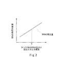
- the set pressure Ps is a pressure at which the BOG usable amount Qa becomes equal to the BOG generation amount Qn.
- the BOG generation amount Qn varies depending on the pressure of the BOG in the tank 11, but substantially depends on the amount of LNG in the tank 11. Further, since the capacity of the tank 11 which is a cargo tank is very large, even when BOG and / or LNG is used as the fuel gas, the height of the liquid level of the LNG in the tank 11 does not change so much. For this reason, in this embodiment, the amount of LNG in the tank 11 is not a variable but is treated as a constant value (different between full load and empty load). Then, the control device 8 calculates the available amount Qa of BOG from the amount of LNG in the tank 11 and the deviation ⁇ P between the calculated pressure Pt of the BOG in the tank 11 and the set pressure Ps. However, when the capacity of the tank 11 is small, a level meter that detects the amount of LNG in the tank 11 may be provided in the tank 11 and the amount of LNG in the tank 11 may be treated as a variable.
- the control device 8 has a deficient amount of LNG obtained by subtracting the BOG usable amount Qa from the total fuel gas consumption Qt, which is the sum of the fuel gas consumption Q1 of the main gas engine 13 and the fuel gas consumption Q2 of the auxiliary gas engine 16. Is supplied to the forced vaporizer 15 through the liquid feed line 41, and the adjustment valve 42 provided in the liquid feed line 41 is controlled. A return line 43 is branched from the liquid supply line 41 on the upstream side of the adjustment valve 42, and the portion of the LNG discharged from the pump 14 that is limited by the adjustment valve 42 is in the tank 11 through the return line 43. Will be returned. Further, the control device 8 controls the regulating valve 45 provided in the extraction line 44 based on the outlet temperature of the cooler 52 detected by the thermometer 84.
- control device 8 determines that the BOG usable amount Qa is larger than the fuel gas consumption Q1 of the main gas engine 13 (when the BOG is greater than the fuel gas consumption Q1 of the main gas engine 13).
- the adjustment valve 62 provided in the bridge line 61 is fully closed, and the adjustment valve 64 provided in the second bridge line 63 is opened to a predetermined opening.
- the control device 8 determines whether the available amount Qa of BOG is smaller than the fuel gas consumption Q1 of the main gas engine 13 (when BOG is insufficient with respect to the fuel gas consumption Q1 of the main gas engine 13).
- the adjustment valve 64 provided in the second bridge line 63 is fully closed, and the adjustment valve 62 provided in the first bridge line 61 is opened to a predetermined opening.
- the control valve 62 is controlled.
- LNG is forcibly vaporized by the forced vaporizer 15 and the VG is supplied to the secondary gas engine 16, so that the secondary gas engine is not used without using a high-pressure pump.
- a sufficient amount of fuel gas can be supplied to 16.
- combustion of the fuel oil in the auxiliary gas engine 16 becomes unnecessary or the consumption amount of the fuel oil can be suppressed.
- the VG generated in the forced vaporizer 15 is taken into the BOG through the first bridge line 61 into the compressor 12. Can be joined. Therefore, a sufficient amount of fuel gas can be supplied to the main gas engine 13 without using a high-pressure pump.
- the forced vaporizer 15 uses steam as a heat source and the cooler 52 is provided on the downstream side of the forced vaporizer 15, the forced vaporization is performed in order to ensure controllability of the outlet temperature of the cooler 52. It is necessary to supply a certain amount of LNG to the vessel 15. In other words, the forced vaporizer 15 has a minimum flow rate. In such a configuration, not only temporarily VG is temporarily generated as the load of the auxiliary gas engine 16 is reduced, but also when the fuel gas consumption of the auxiliary gas engine 16 is lower than the minimum flow rate of the forced carburetor 15. Surplus VG is constantly generated. Accordingly, the return line 71 is particularly useful for such a configuration.
- the control device 8 opens the regulating valve 62 at a predetermined opening, and the pressure Pv of the VG detected by the second pressure gauge 82 exceeds the threshold value ⁇ ,
- the adjustment valve 72 provided in the return line 71 is opened from the fully closed state to a predetermined opening degree.
- control device 8 fully closes the adjustment valve 72 when the pressure Pv of the VG detected by the second pressure gauge 82 exceeds the threshold value ⁇ while the adjustment valve 62 is opened to a predetermined opening degree.
- the opening of the regulating valve 62 may be further increased from the predetermined opening.
- control device 8 fully closes the adjustment valve 72 when the pressure Pv of the VG detected by the second pressure gauge 82 exceeds the threshold value ⁇ while the adjustment valve 62 is kept in the fully closed state. You may open from a state to a predetermined opening degree. In this way, even when VG is not flowing through the first bridge line 61 and the VG supplied to the secondary gas engine 16 through the second supply line 51 is surplus, the surplus VG is returned to the tank 11. can do.
- the pump 14 may have a function of pumping up LNG up to the forced vaporizer 15, and a compressor may be provided in the second supply line 51.
- a compressor may be provided in the second supply line 51.
- a return line 91 may be branched from the first supply line 31, and the return line 91 may be connected to the tank 11, as in the ship 1 ⁇ / b> B of the modified example shown in FIG. 3.
- the tip of the return line 91 may be located above the liquid level of LNG in the tank 11 or may be located below the liquid level.
- the return line 91 is provided with an expansion device 92 such as an expansion valve.
- the second bridge line 63 may be omitted.
- the return line 91 and the liquid supply line 41 are provided with a heat exchanger 93.
- the heat exchanger 93 cools the BOG flowing in the return line 91 upstream of the expansion device 92 (BOG returned to the tank 11) with LNG flowing in the liquid supply line 41.
- the BOG returned to the tank 11 is partially reliquefied.
- the LNG flowing in the liquid feeding line 41 may be partially vaporized by taking heat from the BOG.
- the regulating valve 62 provided in the first bridge line 61 is not necessarily controlled based on the flow rate Qv of the VG detected by the flow meter 83.
- a flow meter (not shown) is provided in the air supply line 21 on the upstream side of the position where the first bridge line 61 is connected, and the BOG flow rate detected by this flow meter becomes the BOG usable amount Qa.
- the regulating valve 62 may be controlled.
- the first bridge line 61 is provided with a third pressure gauge (not shown) for detecting the pressure of the first bridge line 61 on the downstream side of the regulating valve 62, and the BOG detected by the first pressure gauge 81 is provided.
- the adjustment valve 62 may be controlled so that the deviation between the pressure Pb and the pressure of the first bridge line 61 detected by the third pressure gauge becomes a predetermined value.
- the first bridge line 61 may be provided with a pressure reducing valve that outputs a constant secondary pressure even when the primary pressure fluctuates, and a check valve, instead of the regulating valve 62. According to this configuration, VG is automatically replenished when the pressure of the BOG flowing through the air supply line 21 falls below the secondary pressure of the pressure reducing valve.
- the second supply line 51 may not be provided with the cooler 52, the gas-liquid separator 53, and the heater 54.
- main gas engine 13 and the auxiliary gas engine 16 are not necessarily a reciprocating engine, and may be a gas turbine engine.
Landscapes
- Engineering & Computer Science (AREA)
- Chemical & Material Sciences (AREA)
- Mechanical Engineering (AREA)
- Combustion & Propulsion (AREA)
- General Engineering & Computer Science (AREA)
- Ocean & Marine Engineering (AREA)
- Chemical Kinetics & Catalysis (AREA)
- General Chemical & Material Sciences (AREA)
- Oil, Petroleum & Natural Gas (AREA)
- Filling Or Discharging Of Gas Storage Vessels (AREA)
Abstract
Description
本発明は前記実施形態に限定されるものではなく、本発明の要旨を逸脱しない範囲で種々の変形が可能である。
12 圧縮機
13 主ガスエンジン
14 ポンプ
15 強制気化器
16 副ガスエンジン
21 送気ライン
31 第1供給ライン
41 送液ライン
44 抽出ライン
51 第2供給ライン
52 冷却器
53 気液分離器
61 第1ブリッジライン
62 調整弁(第1調整弁)
71 返送ライン
72 調整弁(第2調整弁)
8 制御装置
81 第1圧力計
82 第2圧力計
Claims (4)
- 推進用の主ガスエンジンと、
液化天然ガスを貯留するタンクと、
前記タンク内で発生するボイルオフガスを圧縮機へ導く送気ラインと、
前記圧縮機から吐出されるボイルオフガスを前記主ガスエンジンへ導く第1供給ラインと、
発電用の副ガスエンジンと、
前記タンク内に配置されたポンプから吐出される液化天然ガスを強制気化器へ導く送液ラインと、
前記強制気化器にて生成される気化ガスを前記副ガスエンジンへ導く第2供給ラインと、
前記第2供給ラインから前記送気ラインへ前記気化ガスを導く、開度変更が可能な第1調整弁が設けられたブリッジラインと、
前記第2供給ラインから前記タンクにつながる、開度変更が可能な第2調整弁が設けられた返送ラインと、
前記第1調整弁および前記第2調整弁を制御する制御装置と、
を備える、船舶。 - 前記タンク内のボイルオフガスまたは前記送気ラインに流れるボイルオフガスの圧力を検出する第1圧力計と、
前記第2供給ラインに流れる気化ガスの圧力を検出する第2圧力計と、をさらに備え、
前記制御装置は、前記タンク内の液化天然ガスの量および前記第1圧力計で検出されるボイルオフガスの圧力からボイルオフガスの利用可能量を算出し、前記ボイルオフガスの利用可能量が前記主ガスエンジンの燃料ガス消費量よりも少ない場合には、前記第1調整弁を所定開度に開くとともに、
前記第1調整弁を所定開度に開いている間に、前記第2圧力計で検出される気化ガスの圧力が閾値を上回ったときに、前記第2調整弁を全閉状態から所定開度まで開く、請求項1に記載の船舶。 - 前記タンク内のボイルオフガスまたは前記送気ラインに流れるボイルオフガスの圧力を検出する第1圧力計と、
前記第2供給ラインに流れる気化ガスの圧力を検出する第2圧力計と、をさらに備え、
前記制御装置は、前記タンク内の液化天然ガスの量および前記第1圧力計で検出されるボイルオフガスの圧力からボイルオフガスの利用可能量を算出し、前記ボイルオフガスの利用可能量が前記主ガスエンジンの燃料ガス消費量よりも少ない場合には、前記第1調整弁を所定開度に開くとともに、
前記第1調整弁を所定開度に開いている間に、前記第2圧力計で検出される気化ガスの圧力が閾値を上回ったときに、前記第1調整弁の開度を前記所定開度からさらに大きくする、請求項1に記載の船舶。 - 前記制御装置は、前記第1調整弁を全閉状態に保っている間に、前記第2圧力計で検出される気化ガスの圧力が閾値を上回ったときに、前記第2調整弁を全閉状態から所定開度まで開く、請求項2または3に記載の船舶。
Priority Applications (2)
| Application Number | Priority Date | Filing Date | Title |
|---|---|---|---|
| CN201680073009.2A CN108368796B (zh) | 2015-12-18 | 2016-12-13 | 船舶 |
| KR1020187019548A KR102100435B1 (ko) | 2015-12-18 | 2016-12-13 | 선박 |
Applications Claiming Priority (2)
| Application Number | Priority Date | Filing Date | Title |
|---|---|---|---|
| JP2015247908A JP6600248B2 (ja) | 2015-12-18 | 2015-12-18 | 船舶 |
| JP2015-247908 | 2015-12-18 |
Publications (1)
| Publication Number | Publication Date |
|---|---|
| WO2017104633A1 true WO2017104633A1 (ja) | 2017-06-22 |
Family
ID=59056652
Family Applications (1)
| Application Number | Title | Priority Date | Filing Date |
|---|---|---|---|
| PCT/JP2016/086985 Ceased WO2017104633A1 (ja) | 2015-12-18 | 2016-12-13 | 船舶 |
Country Status (4)
| Country | Link |
|---|---|
| JP (1) | JP6600248B2 (ja) |
| KR (1) | KR102100435B1 (ja) |
| CN (1) | CN108368796B (ja) |
| WO (1) | WO2017104633A1 (ja) |
Cited By (5)
| Publication number | Priority date | Publication date | Assignee | Title |
|---|---|---|---|---|
| CN110944907A (zh) * | 2017-09-08 | 2020-03-31 | 川崎重工业株式会社 | 船舶 |
| CN113074052A (zh) * | 2021-05-07 | 2021-07-06 | 潍柴动力股份有限公司 | 一种混合动力车辆的燃气压力控制方法及混合动力车辆 |
| CN113090417A (zh) * | 2021-03-29 | 2021-07-09 | 招商局重工(深圳)有限公司 | 一种lpg气液分离罐以及燃料控制系统 |
| CN116255561A (zh) * | 2023-02-21 | 2023-06-13 | 江南造船(集团)有限责任公司 | 一种用于双燃料船舶的lng供气系统 |
| CN116658805A (zh) * | 2023-05-26 | 2023-08-29 | 江南造船(集团)有限责任公司 | 一种lng气化系统 |
Families Citing this family (9)
| Publication number | Priority date | Publication date | Assignee | Title |
|---|---|---|---|---|
| US11009185B2 (en) * | 2018-11-16 | 2021-05-18 | China Energy Investment Corporation Limited | Method and system of dispensing liquefied gas |
| KR102626179B1 (ko) * | 2018-12-26 | 2024-01-18 | 한화오션 주식회사 | 연료가스 공급 시스템 및 방법 |
| KR102176543B1 (ko) * | 2019-04-18 | 2020-11-10 | 대우조선해양 주식회사 | 선박의 증발가스 처리 시스템 및 방법 |
| WO2021031196A1 (zh) * | 2019-08-22 | 2021-02-25 | 中集船舶海洋工程设计研究院有限公司 | Lng燃料供气系统及船舶 |
| KR102631166B1 (ko) * | 2019-12-09 | 2024-01-31 | 삼성중공업 주식회사 | 선박용 연료가스공급시스템 |
| KR102439297B1 (ko) * | 2020-08-10 | 2022-09-02 | 삼성중공업(주) | 연료저장탱크의 압력 유지용 장치 및 연료저장탱크의 압력 유지 시스템 |
| CN113006975B (zh) * | 2021-03-05 | 2022-09-09 | 长江三星能源科技股份有限公司 | 一种船舶lng供气系统模拟和测试装置 |
| JP6922113B1 (ja) * | 2021-05-27 | 2021-08-18 | 株式会社神戸製鋼所 | 圧縮機ユニット、圧縮機ユニットの制御プログラムおよび制御方法 |
| CN113734352A (zh) * | 2021-09-24 | 2021-12-03 | 上海外高桥造船有限公司 | 一种具有再冷凝功能的供气系统和工作方法 |
Citations (7)
| Publication number | Priority date | Publication date | Assignee | Title |
|---|---|---|---|---|
| JP2012076561A (ja) * | 2010-09-30 | 2012-04-19 | Mitsubishi Heavy Ind Ltd | 舶用燃料供給システム |
| JP2014108759A (ja) * | 2012-12-04 | 2014-06-12 | Kawasaki Heavy Ind Ltd | 低沸点燃料の移送システム、低沸点燃料の移送方法及び低沸点燃料の燃料供給船 |
| JP2015505941A (ja) * | 2012-10-24 | 2015-02-26 | デウ シップビルディング アンド マリーン エンジニアリング カンパニー リミテッド | 船舶の液化ガス処理システム |
| WO2015036708A2 (fr) * | 2013-09-12 | 2015-03-19 | Cryostar Sas | Dispositif de récupération de vapeurs issues d'un réservoir cryogénique |
| JP2015074418A (ja) * | 2013-10-11 | 2015-04-20 | 三井造船株式会社 | 液化ガス運搬船用燃料ガス供給システム |
| JP2015127510A (ja) * | 2013-12-27 | 2015-07-09 | 川崎重工業株式会社 | 船舶の燃料供給システム |
| JP2015145243A (ja) * | 2015-04-30 | 2015-08-13 | 三井造船株式会社 | 液化ガス運搬船用燃料ガス供給システム |
Family Cites Families (1)
| Publication number | Priority date | Publication date | Assignee | Title |
|---|---|---|---|---|
| KR100894013B1 (ko) * | 2007-09-21 | 2009-04-17 | 현대중공업 주식회사 | 천연가스 재 액화장치 |
-
2015
- 2015-12-18 JP JP2015247908A patent/JP6600248B2/ja not_active Expired - Fee Related
-
2016
- 2016-12-13 CN CN201680073009.2A patent/CN108368796B/zh not_active Expired - Fee Related
- 2016-12-13 KR KR1020187019548A patent/KR102100435B1/ko not_active Expired - Fee Related
- 2016-12-13 WO PCT/JP2016/086985 patent/WO2017104633A1/ja not_active Ceased
Patent Citations (7)
| Publication number | Priority date | Publication date | Assignee | Title |
|---|---|---|---|---|
| JP2012076561A (ja) * | 2010-09-30 | 2012-04-19 | Mitsubishi Heavy Ind Ltd | 舶用燃料供給システム |
| JP2015505941A (ja) * | 2012-10-24 | 2015-02-26 | デウ シップビルディング アンド マリーン エンジニアリング カンパニー リミテッド | 船舶の液化ガス処理システム |
| JP2014108759A (ja) * | 2012-12-04 | 2014-06-12 | Kawasaki Heavy Ind Ltd | 低沸点燃料の移送システム、低沸点燃料の移送方法及び低沸点燃料の燃料供給船 |
| WO2015036708A2 (fr) * | 2013-09-12 | 2015-03-19 | Cryostar Sas | Dispositif de récupération de vapeurs issues d'un réservoir cryogénique |
| JP2015074418A (ja) * | 2013-10-11 | 2015-04-20 | 三井造船株式会社 | 液化ガス運搬船用燃料ガス供給システム |
| JP2015127510A (ja) * | 2013-12-27 | 2015-07-09 | 川崎重工業株式会社 | 船舶の燃料供給システム |
| JP2015145243A (ja) * | 2015-04-30 | 2015-08-13 | 三井造船株式会社 | 液化ガス運搬船用燃料ガス供給システム |
Cited By (8)
| Publication number | Priority date | Publication date | Assignee | Title |
|---|---|---|---|---|
| CN110944907A (zh) * | 2017-09-08 | 2020-03-31 | 川崎重工业株式会社 | 船舶 |
| CN110944907B (zh) * | 2017-09-08 | 2022-04-08 | 川崎重工业株式会社 | 船舶 |
| CN113090417A (zh) * | 2021-03-29 | 2021-07-09 | 招商局重工(深圳)有限公司 | 一种lpg气液分离罐以及燃料控制系统 |
| CN113090417B (zh) * | 2021-03-29 | 2022-07-22 | 招商局重工(深圳)有限公司 | 一种lpg气液分离罐以及燃料控制系统 |
| CN113074052A (zh) * | 2021-05-07 | 2021-07-06 | 潍柴动力股份有限公司 | 一种混合动力车辆的燃气压力控制方法及混合动力车辆 |
| CN116255561A (zh) * | 2023-02-21 | 2023-06-13 | 江南造船(集团)有限责任公司 | 一种用于双燃料船舶的lng供气系统 |
| CN116255561B (zh) * | 2023-02-21 | 2025-08-08 | 江南造船(集团)有限责任公司 | 一种用于双燃料船舶的lng供气系统 |
| CN116658805A (zh) * | 2023-05-26 | 2023-08-29 | 江南造船(集团)有限责任公司 | 一种lng气化系统 |
Also Published As
| Publication number | Publication date |
|---|---|
| JP2017110621A (ja) | 2017-06-22 |
| KR20180090368A (ko) | 2018-08-10 |
| JP6600248B2 (ja) | 2019-10-30 |
| CN108368796B (zh) | 2020-10-02 |
| KR102100435B1 (ko) | 2020-04-13 |
| CN108368796A (zh) | 2018-08-03 |
Similar Documents
| Publication | Publication Date | Title |
|---|---|---|
| JP6600248B2 (ja) | 船舶 | |
| JP6600247B2 (ja) | 船舶 | |
| KR101464118B1 (ko) | 선박, 연료가스 공급장치 및 연료가스 공급방법 | |
| JP6678077B2 (ja) | 船舶 | |
| JP6670088B2 (ja) | 船舶 | |
| JP6401544B2 (ja) | ガス供給システム及びそれを備える船舶 | |
| CN111033024A (zh) | 船舶 | |
| JP2017110797A (ja) | 船舶 | |
| JP6796976B2 (ja) | 船舶 | |
| WO2017078155A1 (ja) | 船舶 | |
| JP6757217B2 (ja) | 船舶 | |
| EP3252289A1 (en) | System and method for controlling fuel supply of ship engine | |
| JP2018103954A (ja) | 船舶 | |
| JP2018103955A (ja) | 船舶 | |
| JP6722074B2 (ja) | 船舶 | |
| KR20180000225U (ko) | 엔진의 연료 공급 시스템 | |
| WO2017077719A1 (ja) | 船舶 | |
| US20260117731A1 (en) | Fuel supply device and engine system | |
| JP2018103960A (ja) | 船舶 |
Legal Events
| Date | Code | Title | Description |
|---|---|---|---|
| 121 | Ep: the epo has been informed by wipo that ep was designated in this application |
Ref document number: 16875610 Country of ref document: EP Kind code of ref document: A1 |
|
| NENP | Non-entry into the national phase |
Ref country code: DE |
|
| ENP | Entry into the national phase |
Ref document number: 20187019548 Country of ref document: KR Kind code of ref document: A |
|
| WWE | Wipo information: entry into national phase |
Ref document number: 1020187019548 Country of ref document: KR |
|
| 122 | Ep: pct application non-entry in european phase |
Ref document number: 16875610 Country of ref document: EP Kind code of ref document: A1 |