WO2017104598A1 - 無線通信装置 - Google Patents
無線通信装置 Download PDFInfo
- Publication number
- WO2017104598A1 WO2017104598A1 PCT/JP2016/086860 JP2016086860W WO2017104598A1 WO 2017104598 A1 WO2017104598 A1 WO 2017104598A1 JP 2016086860 W JP2016086860 W JP 2016086860W WO 2017104598 A1 WO2017104598 A1 WO 2017104598A1
- Authority
- WO
- WIPO (PCT)
- Prior art keywords
- metal plate
- wireless communication
- antenna
- housing
- substrate
- Prior art date
- Legal status (The legal status is an assumption and is not a legal conclusion. Google has not performed a legal analysis and makes no representation as to the accuracy of the status listed.)
- Ceased
Links
Images


Classifications
-
- H—ELECTRICITY
- H01—ELECTRIC ELEMENTS
- H01Q—ANTENNAS, i.e. RADIO AERIALS
- H01Q21/00—Antenna arrays or systems
- H01Q21/24—Combinations of antenna units polarised in different directions for transmitting or receiving circularly and elliptically polarised waves or waves linearly polarised in any direction
- H01Q21/245—Combinations of antenna units polarised in different directions for transmitting or receiving circularly and elliptically polarised waves or waves linearly polarised in any direction provided with means for varying the polarisation
-
- H—ELECTRICITY
- H04—ELECTRIC COMMUNICATION TECHNIQUE
- H04B—TRANSMISSION
- H04B1/00—Details of transmission systems, not covered by a single one of groups H04B3/00 - H04B13/00; Details of transmission systems not characterised by the medium used for transmission
- H04B1/38—Transceivers, i.e. devices in which transmitter and receiver form a structural unit and in which at least one part is used for functions of transmitting and receiving
-
- H—ELECTRICITY
- H01—ELECTRIC ELEMENTS
- H01Q—ANTENNAS, i.e. RADIO AERIALS
- H01Q1/00—Details of, or arrangements associated with, antennas
- H01Q1/12—Supports; Mounting means
- H01Q1/22—Supports; Mounting means by structural association with other equipment or articles
- H01Q1/2291—Supports; Mounting means by structural association with other equipment or articles used in Bluetooth® or Wi-Fi® devices of Wireless Local Area Networks [WLAN]
-
- H—ELECTRICITY
- H01—ELECTRIC ELEMENTS
- H01Q—ANTENNAS, i.e. RADIO AERIALS
- H01Q1/00—Details of, or arrangements associated with, antennas
- H01Q1/12—Supports; Mounting means
- H01Q1/22—Supports; Mounting means by structural association with other equipment or articles
- H01Q1/24—Supports; Mounting means by structural association with other equipment or articles with receiving set
- H01Q1/241—Supports; Mounting means by structural association with other equipment or articles with receiving set used in mobile communications, e.g. GSM
- H01Q1/242—Supports; Mounting means by structural association with other equipment or articles with receiving set used in mobile communications, e.g. GSM specially adapted for hand-held use
- H01Q1/245—Supports; Mounting means by structural association with other equipment or articles with receiving set used in mobile communications, e.g. GSM specially adapted for hand-held use with means for shaping the antenna pattern, e.g. in order to protect user against rf exposure
-
- H—ELECTRICITY
- H01—ELECTRIC ELEMENTS
- H01Q—ANTENNAS, i.e. RADIO AERIALS
- H01Q1/00—Details of, or arrangements associated with, antennas
- H01Q1/36—Structural form of radiating elements, e.g. cone, spiral, umbrella; Particular materials used therewith
- H01Q1/38—Structural form of radiating elements, e.g. cone, spiral, umbrella; Particular materials used therewith formed by a conductive layer on an insulating support
-
- H—ELECTRICITY
- H01—ELECTRIC ELEMENTS
- H01Q—ANTENNAS, i.e. RADIO AERIALS
- H01Q15/00—Devices for reflection, refraction, diffraction or polarisation of waves radiated from an antenna, e.g. quasi-optical devices
- H01Q15/14—Reflecting surfaces; Equivalent structures
-
- H—ELECTRICITY
- H01—ELECTRIC ELEMENTS
- H01Q—ANTENNAS, i.e. RADIO AERIALS
- H01Q19/00—Combinations of primary active antenna elements and units with secondary devices, e.g. with quasi-optical devices, for giving the antenna a desired directional characteristic
- H01Q19/10—Combinations of primary active antenna elements and units with secondary devices, e.g. with quasi-optical devices, for giving the antenna a desired directional characteristic using reflecting surfaces
-
- H—ELECTRICITY
- H04—ELECTRIC COMMUNICATION TECHNIQUE
- H04B—TRANSMISSION
- H04B1/00—Details of transmission systems, not covered by a single one of groups H04B3/00 - H04B13/00; Details of transmission systems not characterised by the medium used for transmission
- H04B1/38—Transceivers, i.e. devices in which transmitter and receiver form a structural unit and in which at least one part is used for functions of transmitting and receiving
- H04B1/3827—Portable transceivers
- H04B1/3888—Arrangements for carrying or protecting transceivers
-
- H—ELECTRICITY
- H04—ELECTRIC COMMUNICATION TECHNIQUE
- H04B—TRANSMISSION
- H04B1/00—Details of transmission systems, not covered by a single one of groups H04B3/00 - H04B13/00; Details of transmission systems not characterised by the medium used for transmission
- H04B1/38—Transceivers, i.e. devices in which transmitter and receiver form a structural unit and in which at least one part is used for functions of transmitting and receiving
- H04B1/40—Circuits
-
- H—ELECTRICITY
- H04—ELECTRIC COMMUNICATION TECHNIQUE
- H04L—TRANSMISSION OF DIGITAL INFORMATION, e.g. TELEGRAPHIC COMMUNICATION
- H04L69/00—Network arrangements, protocols or services independent of the application payload and not provided for in the other groups of this subclass
- H04L69/18—Multiprotocol handlers, e.g. single devices capable of handling multiple protocols
Definitions
- the present invention relates to a wireless communication device.
- a predetermined-length waveguide and reflector A first arrangement in which the positional relationship between the radiator and the radiator can be changed, and the director, the reflector, and the radiator function as a directional antenna having a predetermined interval and parallel to each other;
- an antenna device having a structure capable of switching to a second arrangement that functions as an omnidirectional antenna by changing the arrangement of at least one of a director, a reflector, and a radiation ( Patent Document 1).
- the positional relationship between the director, the reflector, and the radiator can be changed, and the first arrangement that functions as a directional antenna and the second arrangement that functions as an omnidirectional antenna. Therefore, although it is a single antenna device, it can be used as a directional antenna or an omnidirectional antenna.
- Patent Document 1 it is possible to realize an infinite number of radiation patterns by moving the position of the radiator. Depending on the positional relationship between the waver, the reflector and the radiator, there is a problem that the gain is deteriorated.
- the present invention is intended to solve the problems associated with the prior art as described above, and an object of the present invention is to provide a wireless communication apparatus capable of easily changing directivity for general users. There is a place to do.
- a housing a substrate installed inside the housing, an antenna installed on the substrate, a detachable installation on the housing, and a reflectance of the housing
- a metal plate having a higher reflectance than the substrate at the time of installation, a detection unit that detects the installation of the metal plate, and an output unit that outputs a detection result of the detection unit.
- a wireless communication device is provided.
- a casing a board installed inside the casing, an antenna installed on the board, and switching for switching the directivity of the antenna from a first state to a second state
- a wireless communication device including a unit, a detection unit that detects switching by the switching unit, and an output unit that outputs a detection result of the detection unit.
- FIG. 2 is a cross-sectional view taken along the line II of the wireless communication apparatus in FIG. It is the figure (sectional view) which expanded the periphery of the detection part of the radio
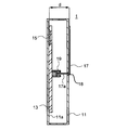
- FIG. 1 is an explanatory diagram (perspective view) for illustrating a schematic configuration of a wireless communication apparatus according to an embodiment of the present invention.
- 2 is a cross-sectional view taken along the line II of the wireless communication apparatus of FIG.
- the wireless communication device 1 includes a housing 11, a substrate 13, antennas 15 a to 15 d, a metal plate 17, an opening 18, and a detection unit 19. In addition, when it is not necessary to distinguish the antennas, they are described as “antenna 15”.
- the casing 11 has a rectangular parallelepiped shape in this example, but may have any shape as long as the antenna 15 and the metal plate 17 can be set to a predetermined distance d.
- the casing 11 is formed of a resin material in this example. But the material which forms the housing
- casing 11 is not limited to a resin material, unless it is a material which becomes a role of reflectors, such as a metal material.
- the casing 11 has an opening 18.
- the opening 18 is located near the center of the housing 11.
- the position of the opening 18 is not limited to the vicinity of the center of the housing 11 as long as the metal plate 17 is disposed at a position facing the antenna when the metal plate 17 is installed in the housing 11.
- the substrate 13 is installed inside the housing 11.
- the substrate 13 is installed on the side surface 11 a inside the housing 11, but a part of the substrate 13 may not be in contact with the side surface 11 a inside the housing 11.
- the substrate 13 is a single layer, but may be a multilayer. In the case of multiple layers, the position where the antenna 15 is installed can be the inner layer as described later.
- the antenna 15 is installed on the substrate 13.
- the number of elements of the antenna 15 is four.
- the number of elements is not limited to this, and may be one or more than four.
- the antenna 15 is a planar antenna in this example.
- the antenna 15 is formed by printing on the substrate 13.
- the antenna 15 is not limited to a printed planar antenna on the substrate 13, and a planar antenna such as a plate inverted F antenna (PIFA: Planar Inverted-F Antenna) or a patch antenna may be mounted on the substrate 13. Good.
- PIFA Planar Inverted-F Antenna
- the antenna 15 is configured on the front surface of the substrate 13 in this example, but may be configured on the back surface.
- the antenna 15 may be configured as an inner layer.
- a known split ring resonator (Split Ring Resonator, not shown) is disposed between the antenna elements.
- the distance between the antenna elements is shorter than when the split ring resonator is not disposed.
- the distance between the antenna elements is ⁇ / 2.
- the distance between the antenna elements is preferably ⁇ or more.
- the antenna 15 is a 5 GHz band wireless communication antenna.
- the distance between the antenna elements is preferably 60 mm or more.
- an antenna for wireless communication in the 2.45 GHz band may also be provided.
- the metal plate 17 has a function of reflecting radio waves.
- the metal plate 17 reflects the radio wave radiated from the antenna 15.
- the reflectance of the metal plate 17 is higher than the reflectance of the housing 11.
- the antenna 15a to the antenna 15d are inside the metal plate 17 in a plan view.
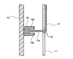
- the protrusion 17a is a part of the metal plate 17 in this example. That is, the protrusion 17a and the metal plate 17 are formed of the same material. When formed of the same material, the protrusion 17a and the metal plate 17 can be manufactured integrally. However, the protrusion 17a and the metal plate 17 may be made of different materials. In the case of another material, it is necessary to join the protrusion 17a and the metal plate 17 together. Further, the protrusion 17 a is inserted into the housing 11.
- the metal plate 17 When the metal plate 17 is installed in the housing 11, the metal plate 17 has a surface facing the substrate 13 and the antenna 15 installed on the substrate 13.
- the number of antenna elements installed on the substrate is four.
- the distance between each antenna and the metal plate 17 is preferably equal. If the distance between each antenna and the metal plate 17 is different, there is a difference in the degree of overlap between the radio wave radiated from each antenna and the radio wave reflected by the metal plate 17, which affects the directivity and the magnitude of the front gain. Because it gives. Therefore, in this example, the four antennas 15 and the metal plate 17 are configured to have the same distance. That is, the four antennas 15 and the metal plate 17 are parallel. In other words, the substrate 13 on which the antenna 15 is installed and the metal plate 17 are preferably parallel.
- the distance d between each antenna 15 and the metal plate 17 is preferably greater than ⁇ / 12 and less than 5 ⁇ / 12 with respect to the radio frequency used. More preferably, the distance d between each antenna 15 and the metal plate 17 is not less than ⁇ / 6 and not more than ⁇ / 3 with respect to the radio frequency used.
- the distance d between each antenna 15 and the metal plate 17 is more preferably ⁇ / 4 with respect to the radio frequency used.
- the radio frequency to be used is the 5 GHz band. Therefore, the distance d between each antenna 15 and the metal plate 17 is more preferably 15 mm.
- FIG. 3 is an enlarged view (sectional view) of the periphery of the detection unit of the wireless communication device according to the embodiment of the present invention.
- the detection unit 19 is a photo interrupter.
- the photo interrupter has a light emitting portion 19a and a light receiving portion 19b that face each other.
- the detection unit 19 can detect that the metal plate 17 is installed in the housing 11 without contacting the protrusion 17a.
- the detection unit 19 is not limited to a photo interrupter, and may be another non-contact sensor.
- FIG. 3A is an enlarged view (sectional view) of the periphery of the detection unit of the wireless communication device when a metal plate is not installed in the housing in the wireless communication device according to the embodiment of the present invention.
- FIG. 3B is an enlarged view (sectional view) of the periphery of the detection unit of the wireless communication device when a metal plate is installed in the housing in the wireless communication device according to the embodiment of the present invention.
- the metal plate 17 When the metal plate 17 is moved in the direction of the arrow in the drawing as shown in FIG. 3A and the light receiving portion 19b detects that the projection 17a blocks the light from the light emitting portion 19a as shown in FIG.
- the part 19A detects that a case including the metal plate 17 is installed in the housing 11.
- FIG. 4 is a block diagram for explaining a part of a wireless communication apparatus according to an embodiment of the present invention.
- the substrate 13 includes an antenna 15, a detection unit 19, an output unit 20, an RF unit 21, a baseband unit 23, and a control unit 25.
- the RF unit 21 processes a frequency band signal used in the wireless communication device 1.
- the RF unit 21 processes a signal of 5 GHz band.
- the RF unit 21 is connected to the antenna 15.
- the RF unit 21 is connected to the baseband unit 23.
- the reception mixer in the RF unit 21 converts the high frequency into an intermediate frequency (IF) and then converts it into a baseband signal.
- the RF unit 21 includes a known configuration such as various mixers for transmission and reception, an amplifier such as an LNA, and a filter such as a bandpass filter, but the description thereof is omitted here.
- the control unit 25 controls the operation mode based on the detection result output by the output unit.
- the control unit 25 performs various controls related to wireless LAN communication, such as retransmission control when an error occurs when a signal transmitted from the transmission side is decoded on the reception side, and transmission timing control. Further, the control unit 25 may perform control so as to reduce the transmission output of the antenna 15 when the detection unit 19 detects that the metal plate 17 is installed in the housing 11.
- the output unit 20 outputs the result detected by the detection unit 19. Then, the output result is used by the control unit 25.
- FIG. 5 is a diagram for explaining a simulation situation for confirming the directivity of the wireless communication apparatus according to the embodiment of the present invention.
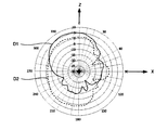
- 6A and 6B are simulation results showing the directivity of the wireless communication apparatus according to the embodiment of the present invention.
- the wireless communication device 1 ⁇ / b> A is installed in a housing 11, a substrate 13 installed in the housing, an antenna 15 a installed in the substrate, and a detachable installation in the housing.
- 1 includes a metal plate (reflecting plate) 17 that is parallel to the substrate 13, a detection unit (not shown) that detects the installation of the metal plate 17, and an output unit (not shown) that outputs the detection result of the detection unit. .
- the antenna 15a is a planar antenna for 5 GHz band.
- the housing 11 is a case made of a resin material.
- the resin case is designed so that the distance between the antenna 15a and the metal plate (reflecting plate) 17 is ⁇ / 4 (15 mm).
- the horizontal direction is the X-axis direction
- the vertical direction is the Y-axis direction
- the vertical direction from the substrate 13 to the opposite side of the metal plate 17 Is the Z-axis direction.
- D1 solid line
- D2 dashed line
- Antenna gain When the metal plate 17 is not attached to the housing 11, the antenna gain in the Z-axis direction is about 1 dBi.
- the antenna gain in the Z-axis direction is about 5 dBi.
- D3 solid line
- D4 broken line
- the antenna gain in the Z-axis direction is about 1 dBi.
- the antenna gain in the Z-axis direction is about 5 dBi. Then, when the metal plate 17 is attached to the housing 11, the antenna gain in the Z-axis direction is increased by 3 dB or more.
- the antenna 15a When the metal plate 17 is attached to the housing 11, the antenna 15a is a highly directional antenna. As you can see, it works. On the other hand, when the metal plate 17 is not attached to the housing 11, the antenna 15a does not have a large antenna gain in any direction, so that it can be seen that it operates as an antenna with low directivity. That is, the metal plate 17 can be said to be a switching unit that switches the antenna directivity from a relatively low state (first state) to a high state (second state). And a detection part detects the switching by this switching part.
- a plurality of antennas are provided on both a transmission side and a reception side, and a MIMO (Multiple Input Multiplex) that configures a multi-input multiple-output system via a wireless transmission path (channel).
- MIMO Multiple Input Multiplex
- the Output method is attracting attention.
- a plurality of antennas are provided with respect to the conventional technique in order to cope with the MIMO method, a problem arises that a plurality of waveguides and reflectors are required.
- a plurality of antennas 15 are formed on one substrate 13. That is, the plurality of antennas 15 are formed in the same plane. And the board
- the detection unit 19 automatically detects whether or not the metal plate 17 is installed in the housing 11. Therefore, the control unit 25 has an effect that the transmission output of the wireless communication device 1 can be automatically switched by the detection.
- the protrusion 17a is made of the same material as the metal plate 17, there is an effect that both can be manufactured integrally.
- the distance between the substrate 13 including the plurality of antennas 15 and the metal plate (reflecting plate) 17 can be determined by the protrusion 17a, and detection by the detection unit 19 is also performed. Therefore, the projection part 17a has an effect that one can play two roles.
- the detection part 19 can detect that the metal plate 17 was installed in the housing
- FIG. 7A is an enlarged view (cross-sectional view) of the periphery of the detection unit of the wireless communication device when a metal plate is not installed in the housing in the wireless communication device according to another embodiment of the present invention.
- FIG. 7B is an enlarged view (cross-sectional view) of the periphery of the detection unit of the wireless communication device when a metal plate is installed in the housing in the wireless communication device according to another embodiment of the present invention.
- This embodiment is substantially the same as the first embodiment, although the detection unit is different. Therefore, description of the same part is omitted, and different points will be described in detail.
- the detection unit 19A is a push switch in this example. Therefore, when the push switch is pushed by the protrusion 17a, it is detected that the metal plate 17 is installed in the housing 11. Accordingly, the detection unit 19A comes into contact with the protrusion 17a.
- the automatic detection of the metal plate 17 by the switch is not limited to the push switch, but may be a lever switch or the like.
- the detection unit 19 is not a non-contact sensor such as a photo interrupter but a push switch.
- the push switch is less expensive than the photo interrupter. Therefore, in this embodiment, there exists an effect that the detection part 19 can be comprised more cheaply.
- FIG. 8 is an explanatory diagram (perspective view) for illustrating a schematic configuration of a wireless communication apparatus according to another embodiment of the present invention.
- 9 is a cross-sectional view of the wireless communication apparatus of FIG. 8 taken along the line II-II.
- This embodiment is substantially the same as the first embodiment, except that the position of the detection unit and the opening are not provided. Therefore, description of the same part is omitted, and only different points will be described in detail.
- the detection unit 19B is a push switch installed on the upper surface of the housing 11. Of the case 16 covering the housing 11, the surface parallel to the substrate 13 is the metal plate 17B.
- the case 16 may be installed in the housing 11 so that the case 16 is difficult to move from the housing 11, and the upper surface of the housing 11 may be provided with irregularities so as to be engaged with the case 16.
- the detection unit 19B may not function. Therefore, the unevenness is provided as long as the detection unit 19B functions.
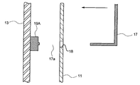
- FIG. 10A is an enlarged view (cross-sectional view) of the periphery of the detection unit of the wireless communication device when a metal plate is not installed in the housing in the wireless communication device according to another embodiment of the present invention.
- FIG. 10B is an enlarged view (cross-sectional view) of the periphery of the detection unit of the wireless communication device when a metal plate is installed in the housing in the wireless communication device according to another embodiment of the present invention.
- the detection unit 19B When the case 16 is moved in the direction of the arrow in the drawing as shown in FIG. 10A and the push switch (detection unit 19B) is pushed by the recess 16a of the case 16 as shown in FIG. 10B, the detection unit 19B is It is detected that a case including the metal plate 17 is installed on the body 11.
- This embodiment also has the same effect as the first embodiment.
- the housing 11 since the detection unit 19B is installed on the upper surface of the housing 11, the housing 11 does not have an opening portion like the opening 18 of the first embodiment. Therefore, when a general user installs the case 16 including the metal plate 17 in the housing 11, the detection unit 19 ⁇ / b> B can be installed while being visually confirmed.
- the control unit when a restriction is provided for the counterpart terminal that communicates with the wireless communication device 1, for example, when a threshold is provided for the reception sensitivity received from the counterpart terminal, the control unit is configured such that the detection unit 19 is provided on the casing 11 and the metal plate is provided on the casing 11.
- the threshold value of the reception sensitivity of the counterpart terminal for communication is changed. For example, when a metal plate (reflecting plate) 17 is not installed in the casing 11 of the wireless communication device 1 and communication is performed with a counterpart terminal receiving at a reception sensitivity of ⁇ 80 dB or more, as shown in FIG.
- the counterpart terminals 30a and 30b communicate with the wireless communication apparatus 1, but the counterpart terminal 30c outside the residence indicated by the broken line does not communicate with the radio communication apparatus 1.
- the control unit determines the counterpart terminals 30a and 30b receiving with a reception sensitivity of ⁇ 80 dBm or more. Communication is performed, but when a metal plate (reflecting plate) 17 is installed in the casing 11, the threshold value is controlled so that communication is performed only with the counterpart terminals 30a and 30b receiving at a reception sensitivity of ⁇ 77 dBm or higher. May be.
- RSSI Received Signal Strength Indication, Received Signal Strength Indicator, or received signal strength.
- RSSI is a circuit or signal for measuring the strength of a signal received by a wireless communication device.
- the threshold of the counterpart terminal with which the wireless communication apparatus communicates can be changed.
- This embodiment is substantially the same as the first embodiment.
- the function of the control unit is different from that of the first embodiment. Therefore, description of the same part is omitted, and different points will be described in detail.
- the control unit may define the modulation method and the wireless LAN standard when the detection unit 19 detects that the metal plate 17 is installed in the housing 11.
- the transmission / reception environment of the wireless communication device is better when the metal plate 17 is installed in the housing 11.
- the detection unit 19 detects that the metal plate 17 is installed in the housing 11
- the modulation method may be changed to 256QAM.
- the detection unit 19 detects that the metal plate 17 is installed in the housing 11, it does not perform IEEE 802.11ac communication but performs other communication such as IEEE 802.11g. It may be.
- the transmission / reception environment of the wireless communication device is better when the metal plate 17 is installed in the housing 11. Therefore, when the detection unit 19 detects that the metal plate 17 is installed in the housing 11, the output unit 20 outputs the detection result, and the control unit 25 installs the metal plate 17 in the housing 11. It is controlled to transmit a signal indicating that it has been detected. Then, the signal is transmitted from the antenna 15 to the counterpart terminal.
- the counterpart terminal receiving the signal can reduce power consumption by suppressing the amplification factor of the intermediate frequency amplifier.
- the wireless communication apparatus transmits a signal indicating whether or not the metal plate 17 is installed in the housing 11 to the counterpart terminal, There is an effect that the counterpart terminal can adaptively reduce the power consumption.
- a plurality of the antennas of the present invention may be installed on the substrate.
- a part of the metal plate may be inserted into the housing.
- the distance between the substrate and the facing surface may be greater than ⁇ / 12 and less than 5 ⁇ / 12.
- the detection unit may detect the installation of the metal plate without contacting a part of the inserted metal plate.
- a control unit for controlling the operation mode may be further included based on the detection result output by the output unit.
- the control unit may reduce the output of the antenna.
- the antenna may transmit the result detected by the detection unit to the receiver side.
Landscapes
- Engineering & Computer Science (AREA)
- Computer Networks & Wireless Communication (AREA)
- Signal Processing (AREA)
- Physics & Mathematics (AREA)
- Electromagnetism (AREA)
- Transceivers (AREA)
- Variable-Direction Aerials And Aerial Arrays (AREA)
- Aerials With Secondary Devices (AREA)
Priority Applications (3)
| Application Number | Priority Date | Filing Date | Title |
|---|---|---|---|
| CN201680073990.9A CN108432044B (zh) | 2015-12-18 | 2016-12-12 | 无线通信设备 |
| US16/006,026 US10892563B2 (en) | 2015-12-18 | 2018-06-12 | Wireless communication device |
| US17/101,344 US11309640B2 (en) | 2015-12-18 | 2020-11-23 | Wireless communication device |
Applications Claiming Priority (2)
| Application Number | Priority Date | Filing Date | Title |
|---|---|---|---|
| JP2015247893A JP6249014B2 (ja) | 2015-12-18 | 2015-12-18 | 無線通信装置 |
| JP2015-247893 | 2015-12-18 |
Related Child Applications (1)
| Application Number | Title | Priority Date | Filing Date |
|---|---|---|---|
| US16/006,026 Continuation US10892563B2 (en) | 2015-12-18 | 2018-06-12 | Wireless communication device |
Publications (1)
| Publication Number | Publication Date |
|---|---|
| WO2017104598A1 true WO2017104598A1 (ja) | 2017-06-22 |
Family
ID=59056557
Family Applications (1)
| Application Number | Title | Priority Date | Filing Date |
|---|---|---|---|
| PCT/JP2016/086860 Ceased WO2017104598A1 (ja) | 2015-12-18 | 2016-12-12 | 無線通信装置 |
Country Status (4)
| Country | Link |
|---|---|
| US (2) | US10892563B2 (https=) |
| JP (1) | JP6249014B2 (https=) |
| CN (1) | CN108432044B (https=) |
| WO (1) | WO2017104598A1 (https=) |
Families Citing this family (4)
| Publication number | Priority date | Publication date | Assignee | Title |
|---|---|---|---|---|
| CN110809837B (zh) * | 2017-06-16 | 2022-04-29 | 雅马哈株式会社 | 无线通信装置 |
| JP6560722B2 (ja) * | 2017-08-29 | 2019-08-14 | 京セラ株式会社 | 受電アンテナ、受電装置、アンテナ部品、及び受電アンテナの組立方法 |
| CN110931938B (zh) * | 2018-09-20 | 2021-04-16 | 宏碁股份有限公司 | 电子装置 |
| CN114095050B (zh) * | 2020-07-29 | 2022-12-27 | 华为技术有限公司 | 一种无线终端 |
Citations (4)
| Publication number | Priority date | Publication date | Assignee | Title |
|---|---|---|---|---|
| JPH0243803A (ja) * | 1988-08-04 | 1990-02-14 | Nippon Telegr & Teleph Corp <Ntt> | パラボラアンテナ |
| JP2000284854A (ja) * | 1999-03-31 | 2000-10-13 | Toshiba Corp | 携帯型電子機器 |
| JP2011015295A (ja) * | 2009-07-03 | 2011-01-20 | Mitsubishi Electric Corp | 無線通信装置 |
| JP2011061861A (ja) * | 2010-12-06 | 2011-03-24 | Toshiba Corp | 電子機器 |
Family Cites Families (6)
| Publication number | Priority date | Publication date | Assignee | Title |
|---|---|---|---|---|
| US6211830B1 (en) * | 1998-06-10 | 2001-04-03 | Matsushita Electric Industrial Co., Ltd. | Radio antenna device |
| TWI280690B (en) * | 2003-03-18 | 2007-05-01 | Tdk Corp | Electronic device for wireless communications and reflector device for wireless communication cards |
| JP3783006B2 (ja) | 2003-07-01 | 2006-06-07 | 株式会社バッファロー | アンテナ装置 |
| KR20090130812A (ko) * | 2008-06-16 | 2009-12-24 | 주식회사 케이엠더블유 | 형상 변경이 가능한 기지국 안테나 |
| JP4649522B2 (ja) * | 2009-05-29 | 2011-03-09 | 株式会社東芝 | ノートブック型パーソナルコンピュータ |
| CN103682635B (zh) * | 2012-09-25 | 2016-01-13 | 西门子公司 | 一种射频识别天线、射频识别天线的控制单元及控制方法和射频识别系统 |
-
2015
- 2015-12-18 JP JP2015247893A patent/JP6249014B2/ja active Active
-
2016
- 2016-12-12 WO PCT/JP2016/086860 patent/WO2017104598A1/ja not_active Ceased
- 2016-12-12 CN CN201680073990.9A patent/CN108432044B/zh active Active
-
2018
- 2018-06-12 US US16/006,026 patent/US10892563B2/en active Active
-
2020
- 2020-11-23 US US17/101,344 patent/US11309640B2/en active Active
Patent Citations (4)
| Publication number | Priority date | Publication date | Assignee | Title |
|---|---|---|---|---|
| JPH0243803A (ja) * | 1988-08-04 | 1990-02-14 | Nippon Telegr & Teleph Corp <Ntt> | パラボラアンテナ |
| JP2000284854A (ja) * | 1999-03-31 | 2000-10-13 | Toshiba Corp | 携帯型電子機器 |
| JP2011015295A (ja) * | 2009-07-03 | 2011-01-20 | Mitsubishi Electric Corp | 無線通信装置 |
| JP2011061861A (ja) * | 2010-12-06 | 2011-03-24 | Toshiba Corp | 電子機器 |
Also Published As
| Publication number | Publication date |
|---|---|
| US20210075126A1 (en) | 2021-03-11 |
| JP2017112578A (ja) | 2017-06-22 |
| US11309640B2 (en) | 2022-04-19 |
| US10892563B2 (en) | 2021-01-12 |
| CN108432044B (zh) | 2021-05-07 |
| JP6249014B2 (ja) | 2017-12-20 |
| US20180294579A1 (en) | 2018-10-11 |
| CN108432044A (zh) | 2018-08-21 |
Similar Documents
| Publication | Publication Date | Title |
|---|---|---|
| US11309640B2 (en) | Wireless communication device | |
| CN113328762B (zh) | 具有天线阵列增减能力的无线网络 | |
| KR101382085B1 (ko) | 휴대용 장치 | |
| US10651670B1 (en) | Electronic devices with wireless charging antenna arrays | |
| CA2837561C (en) | Antenna structure having a shorting leg | |
| US20110148736A1 (en) | Multi-input multi-output antenna for improving isolation | |
| US20120013519A1 (en) | Multiple-input multiple-output (mimo) multi-band antennas with a conductive neutralization line for signal decoupling | |
| WO2018179870A1 (en) | Antenna, configuration method of antenna and wireless communication device | |
| US10164343B2 (en) | Communication device | |
| KR102279153B1 (ko) | 샤크 핀 안테나 | |
| EP2893593B1 (en) | Multiband monopole antenna apparatus with ground plane aperture | |
| US20220399918A1 (en) | Apparatus that supports spatial diversity, at least at reception | |
| US10270176B2 (en) | Communication device | |
| US9837724B2 (en) | Antenna system | |
| KR20180046694A (ko) | 안테나 장치 및 그를 포함하는 전자 장치 | |
| KR20180047392A (ko) | 안테나장치 | |
| US9761931B2 (en) | Wireless network device | |
| JP6841328B2 (ja) | 無線通信装置 | |
| CN112467355B (zh) | 天线系统 | |
| JP4422657B2 (ja) | アンテナ装置 | |
| JP4469320B2 (ja) | アンテナ装置 | |
| US12621040B2 (en) | Gain pattern overlap reduction | |
| JP2013197636A (ja) | 無線通信式携帯型tvチューナ | |
| KR20250017066A (ko) | 빔포밍 신호를 전송하기 위한 전자 장치 및 방법 | |
| KR101956044B1 (ko) | 무선 통신 장치 및 이의 제어 방법 |
Legal Events
| Date | Code | Title | Description |
|---|---|---|---|
| 121 | Ep: the epo has been informed by wipo that ep was designated in this application |
Ref document number: 16875575 Country of ref document: EP Kind code of ref document: A1 |
|
| NENP | Non-entry into the national phase |
Ref country code: DE |
|
| 122 | Ep: pct application non-entry in european phase |
Ref document number: 16875575 Country of ref document: EP Kind code of ref document: A1 |