WO2017094912A1 - Ferrule equipped with optical fiber, and method for manufacturing ferrule equipped with optical fiber - Google Patents
Ferrule equipped with optical fiber, and method for manufacturing ferrule equipped with optical fiber Download PDFInfo
- Publication number
- WO2017094912A1 WO2017094912A1 PCT/JP2016/086030 JP2016086030W WO2017094912A1 WO 2017094912 A1 WO2017094912 A1 WO 2017094912A1 JP 2016086030 W JP2016086030 W JP 2016086030W WO 2017094912 A1 WO2017094912 A1 WO 2017094912A1
- Authority
- WO
- WIPO (PCT)
- Prior art keywords
- optical fiber
- ferrule
- refractive index
- hole
- index matching
- Prior art date
Links
Images


Classifications
-
- G—PHYSICS
- G02—OPTICS
- G02B—OPTICAL ELEMENTS, SYSTEMS OR APPARATUS
- G02B6/00—Light guides; Structural details of arrangements comprising light guides and other optical elements, e.g. couplings
- G02B6/24—Coupling light guides
- G02B6/36—Mechanical coupling means
- G02B6/38—Mechanical coupling means having fibre to fibre mating means
- G02B6/3807—Dismountable connectors, i.e. comprising plugs
- G02B6/381—Dismountable connectors, i.e. comprising plugs of the ferrule type, e.g. fibre ends embedded in ferrules, connecting a pair of fibres
- G02B6/3818—Dismountable connectors, i.e. comprising plugs of the ferrule type, e.g. fibre ends embedded in ferrules, connecting a pair of fibres of a low-reflection-loss type
- G02B6/382—Dismountable connectors, i.e. comprising plugs of the ferrule type, e.g. fibre ends embedded in ferrules, connecting a pair of fibres of a low-reflection-loss type with index-matching medium between light guides
-
- G—PHYSICS
- G02—OPTICS
- G02B—OPTICAL ELEMENTS, SYSTEMS OR APPARATUS
- G02B6/00—Light guides; Structural details of arrangements comprising light guides and other optical elements, e.g. couplings
- G02B6/24—Coupling light guides
- G02B6/36—Mechanical coupling means
-
- G—PHYSICS
- G02—OPTICS
- G02B—OPTICAL ELEMENTS, SYSTEMS OR APPARATUS
- G02B6/00—Light guides; Structural details of arrangements comprising light guides and other optical elements, e.g. couplings
- G02B6/24—Coupling light guides
- G02B6/36—Mechanical coupling means
- G02B6/38—Mechanical coupling means having fibre to fibre mating means
- G02B6/3807—Dismountable connectors, i.e. comprising plugs
- G02B6/381—Dismountable connectors, i.e. comprising plugs of the ferrule type, e.g. fibre ends embedded in ferrules, connecting a pair of fibres
- G02B6/3818—Dismountable connectors, i.e. comprising plugs of the ferrule type, e.g. fibre ends embedded in ferrules, connecting a pair of fibres of a low-reflection-loss type
- G02B6/3821—Dismountable connectors, i.e. comprising plugs of the ferrule type, e.g. fibre ends embedded in ferrules, connecting a pair of fibres of a low-reflection-loss type with axial spring biasing or loading means
-
- G—PHYSICS
- G02—OPTICS
- G02B—OPTICAL ELEMENTS, SYSTEMS OR APPARATUS
- G02B6/00—Light guides; Structural details of arrangements comprising light guides and other optical elements, e.g. couplings
- G02B6/24—Coupling light guides
- G02B6/36—Mechanical coupling means
- G02B6/38—Mechanical coupling means having fibre to fibre mating means
- G02B6/3807—Dismountable connectors, i.e. comprising plugs
- G02B6/3833—Details of mounting fibres in ferrules; Assembly methods; Manufacture
- G02B6/3834—Means for centering or aligning the light guide within the ferrule
- G02B6/3835—Means for centering or aligning the light guide within the ferrule using discs, bushings or the like
- G02B6/3837—Means for centering or aligning the light guide within the ferrule using discs, bushings or the like forwarding or threading methods of light guides into apertures of ferrule centering means
-
- G—PHYSICS
- G02—OPTICS
- G02B—OPTICAL ELEMENTS, SYSTEMS OR APPARATUS
- G02B6/00—Light guides; Structural details of arrangements comprising light guides and other optical elements, e.g. couplings
- G02B6/24—Coupling light guides
- G02B6/36—Mechanical coupling means
- G02B6/38—Mechanical coupling means having fibre to fibre mating means
- G02B6/3807—Dismountable connectors, i.e. comprising plugs
- G02B6/3833—Details of mounting fibres in ferrules; Assembly methods; Manufacture
- G02B6/3853—Lens inside the ferrule
-
- G—PHYSICS
- G02—OPTICS
- G02B—OPTICAL ELEMENTS, SYSTEMS OR APPARATUS
- G02B6/00—Light guides; Structural details of arrangements comprising light guides and other optical elements, e.g. couplings
- G02B6/24—Coupling light guides
- G02B6/36—Mechanical coupling means
- G02B6/38—Mechanical coupling means having fibre to fibre mating means
- G02B6/3807—Dismountable connectors, i.e. comprising plugs
- G02B6/3833—Details of mounting fibres in ferrules; Assembly methods; Manufacture
- G02B6/3855—Details of mounting fibres in ferrules; Assembly methods; Manufacture characterised by the method of anchoring or fixing the fibre within the ferrule
- G02B6/3861—Adhesive bonding
-
- G—PHYSICS
- G02—OPTICS
- G02B—OPTICAL ELEMENTS, SYSTEMS OR APPARATUS
- G02B6/00—Light guides; Structural details of arrangements comprising light guides and other optical elements, e.g. couplings
- G02B6/24—Coupling light guides
- G02B6/36—Mechanical coupling means
- G02B6/38—Mechanical coupling means having fibre to fibre mating means
- G02B6/3807—Dismountable connectors, i.e. comprising plugs
- G02B6/3833—Details of mounting fibres in ferrules; Assembly methods; Manufacture
- G02B6/3867—Details of mounting fibres in ferrules; Assembly methods; Manufacture comprising air venting holes
-
- G—PHYSICS
- G02—OPTICS
- G02B—OPTICAL ELEMENTS, SYSTEMS OR APPARATUS
- G02B6/00—Light guides; Structural details of arrangements comprising light guides and other optical elements, e.g. couplings
- G02B6/24—Coupling light guides
- G02B6/36—Mechanical coupling means
- G02B6/38—Mechanical coupling means having fibre to fibre mating means
- G02B6/3807—Dismountable connectors, i.e. comprising plugs
- G02B6/3869—Mounting ferrules to connector body, i.e. plugs
-
- G—PHYSICS
- G02—OPTICS
- G02B—OPTICAL ELEMENTS, SYSTEMS OR APPARATUS
- G02B6/00—Light guides; Structural details of arrangements comprising light guides and other optical elements, e.g. couplings
- G02B6/24—Coupling light guides
- G02B6/36—Mechanical coupling means
- G02B6/38—Mechanical coupling means having fibre to fibre mating means
- G02B6/3807—Dismountable connectors, i.e. comprising plugs
- G02B6/3873—Connectors using guide surfaces for aligning ferrule ends, e.g. tubes, sleeves, V-grooves, rods, pins, balls
- G02B6/3885—Multicore or multichannel optical connectors, i.e. one single ferrule containing more than one fibre, e.g. ribbon type
-
- G—PHYSICS
- G02—OPTICS
- G02B—OPTICAL ELEMENTS, SYSTEMS OR APPARATUS
- G02B6/00—Light guides; Structural details of arrangements comprising light guides and other optical elements, e.g. couplings
- G02B6/24—Coupling light guides
- G02B6/42—Coupling light guides with opto-electronic elements
- G02B6/4201—Packages, e.g. shape, construction, internal or external details
- G02B6/4204—Packages, e.g. shape, construction, internal or external details the coupling comprising intermediate optical elements, e.g. lenses, holograms
- G02B6/4212—Packages, e.g. shape, construction, internal or external details the coupling comprising intermediate optical elements, e.g. lenses, holograms the intermediate optical element being a coupling medium interposed therebetween, e.g. epoxy resin, refractive index matching material, index grease, matching liquid or gel
-
- G—PHYSICS
- G02—OPTICS
- G02B—OPTICAL ELEMENTS, SYSTEMS OR APPARATUS
- G02B6/00—Light guides; Structural details of arrangements comprising light guides and other optical elements, e.g. couplings
- G02B6/24—Coupling light guides
- G02B6/42—Coupling light guides with opto-electronic elements
- G02B6/4201—Packages, e.g. shape, construction, internal or external details
- G02B6/4204—Packages, e.g. shape, construction, internal or external details the coupling comprising intermediate optical elements, e.g. lenses, holograms
- G02B6/4214—Packages, e.g. shape, construction, internal or external details the coupling comprising intermediate optical elements, e.g. lenses, holograms the intermediate optical element having redirecting reflective means, e.g. mirrors, prisms for deflecting the radiation from horizontal to down- or upward direction toward a device
Definitions
- the present invention relates to a ferrule with an optical fiber and a method for manufacturing a ferrule with an optical fiber.
- Patent Document 1 discloses that an adhesive filling portion is filled and cured with an adhesive in a state where an end face of an optical fiber is abutted against an inner wall of an adhesive filling portion of a ferrule.
- the end face of the fiber peels off from the abutting surface of the inner wall of the adhesive filling section.
- the transmission loss may increase.
- An object of the present invention is to provide a ferrule with an optical fiber capable of suppressing transmission loss.
- a main invention for achieving the above object is a fiber hole into which an optical fiber is inserted, a filling portion filled with a liquid refractive index matching agent, and an opening surface of the fiber hole inside, the opening surface, A filling portion having an opposite facing surface, and the filling portion is filled with the liquid refractive index matching agent in a state where an end face of the optical fiber inserted into the fiber hole is abutted against the facing surface.
- This is a ferrule with an optical fiber.
- transmission loss can be suppressed even if the ferrule is deformed due to environmental changes.
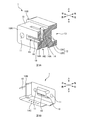
- FIG. 1A and 1B are overall perspective views of the ferrule 1 of the first embodiment.
- FIG. 2 is a cut perspective view of the ferrule 1 of the first embodiment.
- FIG. 3A is a cross-sectional view of the ferrule 1 with an optical fiber of the first embodiment.
- FIG. 3B is a cross-sectional view of a comparative example.
- FIG. 4 is a flowchart of the manufacturing method (assembly procedure) of the ferrule 1 with a fiber.
- FIG. 5A is a cut perspective view of a ferrule 1 of a modification of the first embodiment.
- FIG. 5B is an overall perspective view of a ferrule 1 of a modified example of the first embodiment.
- FIG. 6 is a schematic cross-sectional view of an optical connector using the ferrule 1 of the first embodiment.
- FIG. 7 is a schematic cross-sectional view of the ferrule 1 of the second embodiment.
- a ferrule with an optical fiber, wherein the filling portion is filled with the liquid refractive index matching agent in a state where an end face of the optical fiber inserted into the fiber hole is abutted against the opposing surface Becomes clear. According to such a ferrule with an optical fiber, since the deformation of the ferrule can be suppressed, and even if the ferrule is deformed, the liquid refractive index matching agent enters between the end face of the optical fiber and the facing surface. Can be suppressed.
- the liquid refractive index matching agent is preferably water repellant. Thereby, deterioration of a liquid refractive index matching agent can be suppressed and the physical property of a liquid refractive index matching agent can be maintained.
- liquid refractive index matching agent does not overflow from the filling part when the filling part is opened downward. Thereby, the liquid refractive index matching agent can be held in the filling portion.
- the viscosity of the liquid refractive index matching agent is preferably in the range of 100 to 100,000 mPa ⁇ s. If the viscosity is lower than this range, the liquid refractive index matching agent may be diluted by the condensed water and flow out of the filling portion. Moreover, when the viscosity is higher than this range, it becomes difficult to fill the filling portion with the liquid refractive index matching agent.
- the gap between the fiber hole and the optical fiber is fixed.
- the optical fiber can be fixed to the ferrule.
- a lid for closing the opening of the filling part It is desirable to have a lid for closing the opening of the filling part. Thereby, a liquid refractive index matching agent can be sealed in a filling part.
- FIG. 2 is a cut perspective view of the ferrule 1 of the first embodiment.
- each direction is defined as shown in the figure. That is, the direction of the optical fiber hole 12 is “front-rear direction”, the connection end surface 10A side of the ferrule 1 is “front”, and the opposite side is “rear”. Further, the thickness direction of the ferrule 1 is “vertical direction”, the side of the opening that fills the filling portion 14 with the refractive index matching agent is “upper”, and the opposite side is “lower”. A direction perpendicular to the front-rear direction and the up-down direction is referred to as a “left-right direction”. Note that the width direction of the ferrule 1 is “left-right direction”, and the direction in which the two guide pin holes 11 are arranged is “left-right direction”.
- the arrangement direction of the plurality of optical fiber holes 12 is the “left-right direction”. That is, the arrangement direction of the plurality of optical fibers 3 constituting the optical fiber tape (refer to reference numeral 4 in FIG. 6) attached to the ferrule 1 is the “left-right direction”. In this left-right direction, the right side when viewed from the back is “right”, and the opposite side is “left”.
- the end face of the optical fiber is exposed from the end face of the ferrule. Then, the optical fibers are optically connected by abutting the ferrule end faces and physically connecting the optical fiber end faces.
- the optical fiber end face is not exposed from the ferrule end face 10A.
- the lens unit 16 is disposed in the recess 15 of the ferrule end surface 10A, and an optical signal is input / output from the lens unit 16. That is, in the ferrule 1 of this embodiment, there is no physical contact between the optical fiber end faces. For this reason, even if attachment and detachment are repeated, it does not deteriorate and has high durability.
- the ferrule 1 is a member that holds an end portion of an optical fiber 3 (see FIG. 3A) that transmits an optical signal.
- a front end face 10A (ferrule end face 10A) of the main body 10 of the ferrule 1 serves as a connection end face connected to the other ferrule.
- the main body portion 10 and the flange portion 10B including the ferrule end face 10A are integrally formed of a resin (for example, a transparent resin) that can transmit an optical signal.
- the ends of the plurality of optical fibers 3 are held inside the main body 10.
- the dimension in the front-rear direction of the ferrule 1 of the present embodiment is about 3.5 mm to 5.0 mm, which is shorter than a normal MT ferrule (about 8 mm).
- the main body 10 has a guide pin hole 11, an optical fiber hole 12, a boot hole 13, a filling part 14, a recess 15, a lens part 16, and a light transmission part 18.
- the guide pin hole 11 is a hole for inserting a guide pin (see reference numeral 22 in FIG. 6). By inserting the guide pins into the guide pin holes 11, the ferrules 1 are aligned.
- the guide pin hole 11 penetrates the main body portion 10 in the front-rear direction, and two guide pin holes 11 are opened on the ferrule end surface 10A.
- the two guide pin holes 11 are formed at intervals in the left-right direction so as to sandwich the plurality of optical fiber holes 12 from the left and right. Between the two guide pin holes 11, in addition to the optical fiber hole 12, a boot hole 13, a recess 15, a lens part 16 and a light transmission part 18 are also arranged.
- the optical fiber hole 12 is a hole for inserting the optical fiber 3.
- the optical fiber hole 12 is also a hole for positioning the optical fiber 3.
- the optical fiber hole 12 penetrates between the boot hole 13 and the filling portion 14.
- a bare fiber obtained by removing the coating from the optical fiber core wire is inserted into the optical fiber hole 12.
- the optical fiber holes 12 are parallel to the front-rear direction, and the plurality of optical fiber holes 12 are arranged side by side in the left-right direction. That is, a plurality of optical fiber holes 12 parallel to each other are arranged in the left-right direction.
- Each optical fiber hole 12 has a tapered portion 12A and a fiber fixing portion 12B.
- the tapered portion 12A is provided at the rear end portion of the optical fiber hole 12, and has a tapered shape that widens toward the rear side. By providing such a tapered portion 12 ⁇ / b> A, the optical fiber 3 can be easily inserted into the optical fiber hole 12.
- the fiber fixing part 12B is provided in front of the taper part 12A, and has substantially the same size (diameter) as the diameter of the optical fiber 3. Thereby, the optical fiber 3 inserted in the optical fiber hole 12 can be positioned.
- the boot hole 13 is provided on the rear end face of the ferrule 1.
- the boot hole 13 is a hole for receiving and fixing a boot (see reference numeral 26 in FIG. 3A) attached to the optical fiber 3.
- the filling portion 14 is a hollow portion for filling the refractive index matching agent.
- the filling portion 14 is a cavity that is long in the left-right direction (longer than the length in which the plurality of optical fiber holes 12 and the lens portion 16 are arranged in the left-right direction).
- the filling portion 14 is opened on the upper surface of the main body portion 10 of the ferrule 1.
- the opening of the filling portion 14 is also an opening elongated in the left-right direction (longer than the length in which the plurality of optical fiber holes 12 and the lens portion 16 are arranged in the left-right direction) on the upper surface of the main body portion 10 of the ferrule 1.
- the filling portion 14 is filled with a liquid refractive index matching agent instead of a curing adhesive (described later).
- the filling portion 14 has an optical fiber hole opening surface 14A and an abutting surface 14B.
- the optical fiber hole opening surface 14 ⁇ / b> A is an inner wall on the rear side of the filling portion 14.
- a plurality of optical fiber holes 12 are opened side by side in the left-right direction on the optical fiber hole opening surface 14A.
- the abutting surface 14B is an inner wall on the front side of the filling portion 14 and is a facing surface facing the optical fiber hole opening surface 14A.
- the abutting surface 14B is opposed to the opening of the optical fiber hole 12 in the optical fiber hole opening surface 14A, and is a surface against which the end surface of the optical fiber 3 is abutted.
- the recess 15 is a portion that is recessed with respect to the ferrule end face 10A.
- the recess 15 is provided between the two guide pin holes 11 on the ferrule end surface 10A.
- the recess 15 has a rectangular shape elongated in the left-right direction so as to correspond to the plurality of optical fiber holes 12.
- the lens portion 16 is provided on the bottom surface (rear surface) of the recess 15.
- the lens unit 16 is disposed corresponding to each of the plurality of optical fibers 3 (in other words, the plurality of optical fiber holes 12), and an optical signal is input / output through the lens unit 16.
- the lens unit 16 is formed so as to function as a collimating lens, for example. By inputting / outputting an optical signal whose diameter is enlarged by the lens unit 16, it is possible to reduce the influence of dust and the like in the optical path, and to suppress transmission loss of the optical signal.
- the light transmitting portion 18 transmits a light signal between the ferrule end surface 10A (specifically, the lens portion 16 of the recess 15 of the ferrule end surface 10A) and the abutting surface 14B of the filling portion 14 (an optical path is formed).
- the main body 10 of the present embodiment is integrally formed of a resin that transmits an optical signal. However, it is sufficient that at least a portion where the optical path is formed (the light transmitting portion 18) can transmit the optical signal. Other parts may be made of another material (a material that does not transmit an optical signal).
- FIG. 3B is a cross-sectional view of a comparative example.
- the filling portion 14 is an adhesive filling portion (adhesive filling window), and the filling portion 14 is filled with a curable adhesive (for example, an ultraviolet curable adhesive or a thermosetting adhesive).
- a curable adhesive for example, an ultraviolet curable adhesive or a thermosetting adhesive.
- the ferrule 1 is deformed as described above, but the ferrule 1 is not deformed on the lower side of the ferrule 1 due to the bottom wall of the ferrule 1, and as a result, the ferrule 1 is deformed so as to warp as shown by a dotted line in the figure. Resulting in. Examples of the cause of the shrinkage of the adhesive include a high-temperature and high-humidity environment and curing of the adhesive. Further, when the ferrule 1 is deformed so as to warp as shown by the dotted line in FIG. 3B, the end face of the optical fiber 3 is peeled off from the abutting surface 14B. As a result, the end face of the optical fiber 3 and the abutting face 14B are separated.
- a peeling layer air layer
- transmission loss may increase.
- the end face of the optical fiber is exposed from the end face of the ferrule, and the end face of the optical fiber is the inner wall (the abutting face 14B) of the filling portion 14 as in this embodiment. )
- the adhesive in the adhesive filling portion shrinks and deforms so that the ferrule is warped, the optical fiber end face and the abutting face 14B are separated. There is no problem.
- the problem of peeling off the end face of the optical fiber is a problem peculiar to the structure in which the end face of the optical fiber is abutted against the inner wall (abutting face 14B) of the filling portion 14 as in the comparative example and this embodiment.
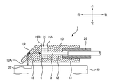
- FIG. 3A is a cross-sectional view of the ferrule 1 with an optical fiber of the first embodiment.
- the filling portion 14 is filled with the liquid refractive index matching agent 5.
- the liquid refractive index matching agent 5 filled in the filling portion 14 is held as a liquid without being cured.
- the filler filled in the filling portion 14 is a liquid, deformation of the ferrule 1 due to the shrinkage of the adhesive as in the comparative example does not occur, so an increase in transmission loss can be suppressed.
- the liquid refractive index matching agent 5 enters the gap between the optical fiber 3 and the abutting surface 14B.
- An increase in transmission loss can be suppressed.
- the effect of suppressing transmission loss can be obtained synergistically.
- the liquid refractive index matching agent 5 has physical properties (viscosity, etc.) that can be filled (injected) into the filling portion 14 and physical properties that do not overflow from the filling portion 14 even if the ferrule 1 is turned upside down. ing.
- the viscosity of the liquid refractive index matching agent 5 is preferably from 100 to 100,000 mPa ⁇ s, and more preferably from 10,000 to 100,000 mPa ⁇ s. The reason is as described below.
- the suitable viscosity of the liquid refractive index matching agent 5 is 100 ⁇ It was 100,000 mPa ⁇ s.
- the appropriate viscosity of the liquid refractive index matching agent 5 was in the range of 10,000 mPa ⁇ s to 100,000 mPa ⁇ s.
- the viscosity of the liquid refractive index matching agent 5 is preferably from 100 to 100,000 mPa ⁇ s, and more preferably from 10,000 to 100,000 mPa ⁇ s.
- the liquid refractive index matching agent 5 is adjusted so that the refractive index difference from the optical fiber 3 becomes small in order to suppress Fresnel reflection.
- the refractive index difference between the liquid refractive index matching agent 5 and the optical fiber 3 is preferably within 0.1, and more preferably within 0.05.
- liquid refractive index matching agent 5 water-repellent silicone oil is used here. Since the liquid refractive index matching agent 5 is not hydrophilic but water repellant, even if water droplets or the like adhere to the ferrule with an optical fiber, moisture is absorbed by the liquid refractive index matching agent 5 filled in the filling portion 14. Therefore, the liquid refractive index matching agent 5 does not deteriorate due to dilution or the like, and the physical properties of the liquid refractive index matching agent 5 can be maintained.
- the liquid refractive index matching agent 5 is not limited to the silicone type, and may be other polymer oils.
- the end portion of the optical fiber 3 cannot be directly fixed at the filling portion 14 as in the comparative example. Therefore, in this embodiment, the boot 26 and the optical fiber 3 are fixed with an adhesive, and the boot 26 and the ferrule 1 (the inner wall surface of the boot hole 13) are fixed with an adhesive. Thereby, the optical fiber 3 is fixed to the ferrule 1. Further, the optical fiber hole 12 and the optical fiber 3 are fixed with an adhesive, whereby the optical fiber 3 may be fixed to the ferrule 1.
- FIG. 4 is a flowchart of the manufacturing method (assembly procedure) of the ferrule 1 with a fiber.
- the operator prepares the ferrule 1 of the present embodiment (S101), inserts each optical fiber 3 of the optical fiber tape into which the boot 26 has been inserted in advance into the optical fiber hole 12 of the ferrule 1, and also boots 26 Is inserted into the boot hole 13 of the ferrule 1 (S102).
- the optical fiber end face is projected from the optical fiber hole opening face 14A.
- the end face of the optical fiber is not abutted against the abutting surface 14B of the filling portion 14. This is because dust or the like may adhere to the end face of the optical fiber when the optical fiber 3 is passed through the optical fiber hole 12.
- the worker cleans the optical fiber end face protruding from the optical fiber hole opening face 14A of the filling portion 14 (S103). For example, the operator blows off dust on the end face of the optical fiber by blowing air from the opening of the filling unit 14. Thereby, dust on the end face of the optical fiber attached when inserted into the optical fiber hole 12 can be removed.
- the filling of the filling portion 14 with the liquid refractive index matching agent is not performed before the optical fiber 3 is inserted, but after the optical fiber 3 is inserted. ing.
- the operator slides the optical fiber 3 (optical fiber tape) forward with respect to the boot 26 and abuts the end face of the optical fiber against the abutment surface 14B of the filling portion 14 (S104). At this stage, an air layer exists between the end face of the optical fiber and the abutting surface 14B.
- the worker fixes the optical fiber 3 to the ferrule 1 at the rear part of the ferrule 1 (S105).
- the operator fills the adhesive filling portion 26 ⁇ / b> A (see the dotted line in FIG. 3A) provided in the boot 26 with a thermosetting adhesive and allows the adhesive to penetrate into the fiber insertion hole of the boot 26.
- the adhesive is infiltrated between the boot 26 and the optical fiber 3.
- the adhesive filling portion 26A (see the dotted line in FIG. 3A) of the boot 26 is filled with the adhesive, and the adhesive is infiltrated between the boot 26 and the ferrule 1 (the inner wall surface of the boot hole 13). Note that the adhesive filling portion 26A (see the dotted line in FIG.
- the boot 26 may be filled with an adhesive so that the adhesive penetrates between the optical fiber hole 12 and the optical fiber 3. After infiltrating each part with the thermosetting adhesive, the operator heats and cures the adhesive, whereby the optical fiber 3 is bonded and fixed to the ferrule 1.
- the method for applying the adhesive is not limited to the one using the adhesive filling portion 26A.
- the operator fills the filling portion 14 with the liquid refractive index matching agent 5 (S106).
- the liquid refractive index matching agent 5 By filling the liquid refractive index matching agent 5 between the end face of the optical fiber and the abutting surface 14B, transmission loss of the optical signal is suppressed.
- the liquid refractive index matching agent 5 penetrates between the optical fiber end face and the abutting surface 14B due to the capillary phenomenon of the liquid refractive index matching agent 5, the gap between the optical fiber end face and the abutting face 14B. Air bubbles hardly remain.
- the ferrule 1 with a fiber of the present embodiment is completed.
- the manufacturing method of the ferrule 1 with a fiber described above since the deformation of the ferrule 1 can be suppressed, transmission loss can be suppressed, and even if the ferrule 1 is deformed, liquid refraction is caused between the end face of the optical fiber and the abutting surface 14B. Since the rate matching agent 5 enters, the transmission loss can be suppressed, so that the effect of suppressing the transmission loss can be obtained synergistically.
- FIG. 5A is a cut perspective view of a ferrule 1 of a modification of the first embodiment.
- FIG. 5B is an overall perspective view of a ferrule 1 of a modified example of the first embodiment.
- a vent hole 14C is formed at the bottom of the filling portion 14.
- the liquid refractive index matching agent 5 needs to have physical properties that do not leak from the vent hole 14C.
- the opening of the vent 14 ⁇ / b> C may be made smaller than the opening above the filling part 14.
- the vent hole 14C is provided on the bottom surface of the filling unit 14, it is difficult for bubbles to be formed on the bottom of the filling unit 14, and the working time for filling the liquid refractive index matching agent into the filling unit 14 can be shortened. The effect is also obtained.
- a plurality of small vents 14C are arranged side by side in the left-right direction, but the number of vents 14C may be one, or may be an elongated opening in the left-right direction. .
- the ferrule 1 may have a lid for closing the upper opening of the filling portion 14.
- a lid By closing the filling part 14 with a lid, the liquid refractive index matching agent 5 can be sealed in the filling part 14.
- This lid is preferably made of a resin having a linear expansion coefficient comparable to that of the resin constituting the ferrule 1.
- the lid can be made of the same resin as the ferrule 1.
- the lid is, for example, a plate-like body having the same shape as the upper opening of the filling unit 14. The lid is fitted into the opening, and is fixed to the ferrule 1 with an adhesive having a linear expansion coefficient similar to that of the ferrule 1.
- FIG. 6 is a schematic cross-sectional view of an optical connector using the ferrule 1 of the first embodiment.
- the ferrule 1 of this embodiment can be used by being housed in a housing 20 of an optical connector.
- the housing 20 is a member that accommodates the ferrule 1 so as to be retractable.
- a protrusion 20A is formed in the internal space of the housing 20, and the ferrule 1 is urged forward by the repulsive force of the spring 24 in a state where the protrusion 20A and the flange 10B of the ferrule 1 are engaged. Yes.
- a guide pin 22 is inserted into the two guide pin holes 11 of the ferrule 1, and the guide pin 22 positions the mating optical connector with the ferrule 1.
- a boot 26 is inserted into the boot hole 13 of the ferrule 1.
- the boot 26 is a cylindrical member having a substantially rectangular cross section, and the plurality of optical fibers 3 of the optical fiber tape 4 penetrate in the front-rear direction.
- the dimensions of the boot 26 in the left-right direction and the vertical direction are substantially the same as the dimensions of the boot hole 13, and the boot 26 is fitted in the boot hole 13.
- the maximum loss increase amount among the loss increase amounts of the eight optical fibers of the 8-fiber optical fiber tape was 1.0 dB in the comparative example, but was 0.3 dB or less in the present embodiment. Most of the eight optical fibers of the comparative examples had a loss increase exceeding 0.3 dB. That is, when an optical fiber having an increase in loss of 0.3 dB or more is evaluated as “defective”, in the comparative example, almost all optical fibers are evaluated as “defective”, whereas in this embodiment, “defective”. There was no optical fiber to be evaluated.
- FIG. 7 is a schematic cross-sectional view of the ferrule 1 of the second embodiment.
- symbol is attached
- the ferrule 1 of the second embodiment is fixed on the photoelectric conversion module 30 via a holder (not shown).
- a positioning pin (not shown) is formed on the lower surface of the ferrule 1, and the positioning pin is fitted into a positioning hole (not shown) of a holder (not shown) bonded and fixed to the upper surface of the photoelectric conversion module 30.
- the ferrule 1 is positioned with respect to the photoelectric conversion module 30.
- the optical element 32 of the photoelectric conversion module 30 include a light emitting element such as a semiconductor laser, or a light receiving element such as a photodiode.
- the main body portion 10 of the ferrule 1 of the second embodiment is integrally molded with a resin that transmits an optical signal, like the main body portion 10 of the first embodiment.
- the lower surface of the main body 10 is a ferrule end surface 10A.
- the ferrule 1 has a plurality of optical fiber holes 12 arranged in the left-right direction (perpendicular to the paper surface) and a filling portion 14.
- the filling portion 14 is provided with an optical fiber hole opening surface 14A and an abutting surface 14B facing the opening of the optical fiber hole 12 (opposing surface facing the optical fiber hole opening surface 14A).
- a portion of the main body 10 that is in front of the abutting surface 14 ⁇ / b> B of the filling portion 14 is a light transmission portion 18, and the light transmission portion 18 is provided with a reflection portion 19.
- the reflecting portion 19 has an inclined surface that is inclined rearward as it goes upward.
- the reflection unit 19 reflects light incident on the ferrule end face 10A toward the end face of the optical fiber 3 (light parallel to the vertical direction becomes light parallel to the front-rear direction). Convert).
- the reflection unit 19 reflects light emitted from the end face of the optical fiber 3 toward the optical element 32 (light parallel to the front-rear direction is light parallel to the vertical direction). To As described above, the reflection unit 19 reflects light (optical signal) in order to convert the optical path.
- the filling portion 14 is filled with the liquid refractive index matching agent 5.
- the liquid refractive index matching agent 5 filled in the filling portion 14 is held as a liquid without being cured. Also in the second embodiment, since the deformation of the ferrule 1 can be suppressed, transmission loss can be suppressed, and even if the ferrule 1 is deformed, the liquid refractive index matching agent 5 enters between the end face of the optical fiber and the abutting surface 14B. Therefore, since transmission loss can be suppressed, the effect of suppressing transmission loss can be obtained synergistically.
Landscapes
- Physics & Mathematics (AREA)
- General Physics & Mathematics (AREA)
- Optics & Photonics (AREA)
- Optical Couplings Of Light Guides (AREA)
- Mechanical Coupling Of Light Guides (AREA)
Abstract
The present disclosure is a ferrule equipped with an optical fiber, the ferrule provided with a fiber hole through which the optical fiber is inserted, and a filling part filled with a refractive-index-matching agent, the filling agent part having an opening surface for the fiber hole in the interior and an opposing surface opposing the opening surface. The ferrule equipped with an optical fiber, characterized in that the filling part is filled with the refractive-index-matching agent once the end surface of the optical fiber inserted into the fiber hole abuts the opposing surface.
Description
本発明は、光ファイバ付きフェルール、及び光ファイバ付きフェルールの製造方法に関する。
The present invention relates to a ferrule with an optical fiber and a method for manufacturing a ferrule with an optical fiber.
光ファイバの端部を保持するフェルールとして、接着剤を充填するための開口が設けられた接着剤充填部を備え、接着剤充填部に接着剤を充填して光ファイバを固定させるようにしたものが知られている。特許文献1には、フェルールの接着剤充填部の内壁に光ファイバの端面を突き当てた状態で、接着剤充填部に接着剤を充填硬化させることが開示されている。
The ferrule that holds the end of the optical fiber has an adhesive filling part with an opening for filling the adhesive, and the optical fiber is fixed by filling the adhesive filling part with the adhesive. It has been known. Patent Document 1 discloses that an adhesive filling portion is filled and cured with an adhesive in a state where an end face of an optical fiber is abutted against an inner wall of an adhesive filling portion of a ferrule.
接着剤充填部に接着剤を充填して硬化させた後、高温・高湿などの環境変化によってフェルールが変形すると、ファイバの端面が接着剤充填部の内壁の突き当て面から剥離し、この結果、伝送損失の増加するおそれがある。
After the adhesive filling section is filled with adhesive and cured, when the ferrule is deformed due to environmental changes such as high temperature and high humidity, the end face of the fiber peels off from the abutting surface of the inner wall of the adhesive filling section. The transmission loss may increase.
本発明は、伝送損失を抑制可能な光ファイバ付きフェルールを提供することを目的とする。
An object of the present invention is to provide a ferrule with an optical fiber capable of suppressing transmission loss.
上記目的を達成するための主たる発明は、光ファイバを挿入させたファイバ穴と、液状屈折率整合剤を充填させた充填部であって、内部に前記ファイバ穴の開口面と、前記開口面と対向する対向面とを有する充填部と、を備え、前記ファイバ穴に挿入させた前記光ファイバの端面を前記対向面に突き当てた状態で、前記充填部に前記液状屈折率整合剤が充填されていることを特徴とする光ファイバ付きフェルールである。
A main invention for achieving the above object is a fiber hole into which an optical fiber is inserted, a filling portion filled with a liquid refractive index matching agent, and an opening surface of the fiber hole inside, the opening surface, A filling portion having an opposite facing surface, and the filling portion is filled with the liquid refractive index matching agent in a state where an end face of the optical fiber inserted into the fiber hole is abutted against the facing surface. This is a ferrule with an optical fiber.
本発明の他の特徴については、後述する明細書及び図面の記載により明らかにする。
Other features of the present invention will be made clear by the description and drawings described later.
本発明によれば、仮に環境変化によってフェルールが変形しても、伝送損失を抑制することができる。
According to the present invention, transmission loss can be suppressed even if the ferrule is deformed due to environmental changes.
後述する明細書及び図面の記載から、少なくとも以下の事項が明らかとなる。
At least the following matters will become clear from the description and drawings described below.
光ファイバを挿入させたファイバ穴と、液状屈折率整合剤を充填させた充填部であって、内部に前記ファイバ穴の開口面と、前記開口面と対向する対向面とを有する充填部と、を備え、前記ファイバ穴に挿入させた前記光ファイバの端面を前記対向面に突き当てた状態で、前記充填部に前記液状屈折率整合剤が充填されていることを特徴とする光ファイバ付きフェルールが明らかとなる。このような光ファイバ付きフェルールによれば、フェルールの変形を抑制できるため、また、仮にフェルールが変形しても光ファイバ端面と前記対向面との間に液状屈折率整合剤が入り込むため、伝送損失を抑制することができる。
A fiber hole into which an optical fiber is inserted, and a filling part filled with a liquid refractive index matching agent, the filling part having an opening surface of the fiber hole inside and an opposing surface facing the opening surface; A ferrule with an optical fiber, wherein the filling portion is filled with the liquid refractive index matching agent in a state where an end face of the optical fiber inserted into the fiber hole is abutted against the opposing surface Becomes clear. According to such a ferrule with an optical fiber, since the deformation of the ferrule can be suppressed, and even if the ferrule is deformed, the liquid refractive index matching agent enters between the end face of the optical fiber and the facing surface. Can be suppressed.
前記液状屈折率整合剤は撥水性であることが望ましい。これにより、液状屈折率整合剤の劣化を抑制し、液状屈折率整合剤の物性を維持できる。
The liquid refractive index matching agent is preferably water repellant. Thereby, deterioration of a liquid refractive index matching agent can be suppressed and the physical property of a liquid refractive index matching agent can be maintained.
前記充填部の開口を下にしたときに、前記液状屈折率整合剤が前記充填部から溢れ出ないことが望ましい。これにより、充填部に液状屈折率整合剤を保持できる。
It is desirable that the liquid refractive index matching agent does not overflow from the filling part when the filling part is opened downward. Thereby, the liquid refractive index matching agent can be held in the filling portion.
前記液状屈折率整合剤の粘度は、100~100000mPa・sの範囲内であることが望ましい。この範囲よりも粘度が低いと、結露した水分によって液状屈折率整合剤が希釈化して充填部から流出するおそれがある。また、この範囲よりも粘度が高いと、充填部に液状屈折率整合剤を充填しにくくなる。
The viscosity of the liquid refractive index matching agent is preferably in the range of 100 to 100,000 mPa · s. If the viscosity is lower than this range, the liquid refractive index matching agent may be diluted by the condensed water and flow out of the filling portion. Moreover, when the viscosity is higher than this range, it becomes difficult to fill the filling portion with the liquid refractive index matching agent.
前記光ファイバを挿通させたブーツと前記光ファイバとの間が固定されており、フェルールに設けられたブーツ穴と前記ブーツとの間が固定されていることが望ましい。これにより、光ファイバをフェルールに対して固定できる。
It is desirable that a space between the boot through which the optical fiber is inserted and the optical fiber is fixed, and a space between the boot hole provided in the ferrule and the boot is fixed. Thereby, the optical fiber can be fixed to the ferrule.
前記ファイバ穴と前記光ファイバとの間が固定されていることが望ましい。これにより、光ファイバをフェルールに対して固定できる。
It is desirable that the gap between the fiber hole and the optical fiber is fixed. Thereby, the optical fiber can be fixed to the ferrule.
フェルールの端面に対して凹んだ凹所と、前記凹所に形成され、前記光ファイバ穴に対応して配置されたレンズ部とを備えることが望ましい。これにより、光ファイバ端面同士の物理的な接触を無くし、耐久性を高めることができる。
It is desirable to include a recess that is recessed with respect to the end face of the ferrule and a lens portion that is formed in the recess and is disposed corresponding to the optical fiber hole. Thereby, the physical contact between optical fiber end surfaces can be eliminated, and durability can be enhanced.
前記充填部の底に通気口が形成されていることが望ましい。これにより、充填部の底に気泡が形成されにくくなるとともに、液状屈折率整合剤の充填作業が容易になる。
It is desirable that a vent is formed at the bottom of the filling part. This makes it difficult for bubbles to form at the bottom of the filling portion, and facilitates the filling operation of the liquid refractive index matching agent.
前記充填部の開口を塞ぐための蓋を有することが望ましい。これにより、液状屈折率整合剤を充填部に密閉できる。
It is desirable to have a lid for closing the opening of the filling part. Thereby, a liquid refractive index matching agent can be sealed in a filling part.
(1)光ファイバを挿入させるためのファイバ穴と、液状屈折率整合剤を充填させるための充填部であって、内部に前記ファイバ穴の開口面と、前記開口面と対向する対向面とを有する充填部と、を備えたフェルールを準備すること、(2)前記光ファイバを前記光ファイバ穴に挿入し、前記開口面から突出した前記光ファイバの端面を前記対向面に突き当てること、及び(3)前記光ファイバの端面を前記対向面に突き当てた状態で、前記充填部に前記液状屈折率整合剤を充填することを行う光ファイバ付きフェルールの製造方法が明らかとなる。これにより、伝送損失を抑制可能な光ファイバ付きフェルールを提供することができる。
(1) A fiber hole for inserting an optical fiber, a filling portion for filling a liquid refractive index matching agent, and an opening surface of the fiber hole and a facing surface facing the opening surface inside And (2) inserting the optical fiber into the optical fiber hole, and abutting the end surface of the optical fiber protruding from the opening surface against the facing surface; and (3) The manufacturing method of the ferrule with an optical fiber which fills the filling part with the liquid refractive index matching agent in a state where the end surface of the optical fiber is abutted against the facing surface becomes clear. Thereby, the ferrule with an optical fiber which can suppress transmission loss can be provided.
===第1実施形態===
<構成>
図1A及び図1Bは、第1実施形態のフェルール1の全体斜視図である。図2は、第1実施形態のフェルール1の切断斜視図である。 === First Embodiment ===
<Configuration>
1A and 1B are overall perspective views of theferrule 1 of the first embodiment. FIG. 2 is a cut perspective view of the ferrule 1 of the first embodiment.
<構成>
図1A及び図1Bは、第1実施形態のフェルール1の全体斜視図である。図2は、第1実施形態のフェルール1の切断斜視図である。 === First Embodiment ===
<Configuration>
1A and 1B are overall perspective views of the
以下の説明では、図に示すように各方向を定義する。すなわち、光ファイバ穴12の方向を「前後方向」とし、フェルール1の接続端面10Aの側を「前」とし、逆側を「後」とする。また、フェルール1の厚み方向を「上下方向」とし、充填部14に屈折率整合剤を充填する開口の側を「上」とし、逆側を「下」とする。また、前後方向及び上下方向に垂直な方向を「左右方向」とする。なお、フェルール1の幅方向が「左右方向」となり、2つのガイドピン穴11の並ぶ方向が「左右方向」となる。また、複数の光ファイバ穴12の並び方向が「左右方向」となる。すなわち、フェルール1に取り付けられる光ファイバテープ(図6の符号4参照)を構成する複数の光ファイバ3の並び方向が「左右方向」となる。この左右方向において、後から前を見たときの右側を「右」とし、逆側を「左」とする。
In the following explanation, each direction is defined as shown in the figure. That is, the direction of the optical fiber hole 12 is “front-rear direction”, the connection end surface 10A side of the ferrule 1 is “front”, and the opposite side is “rear”. Further, the thickness direction of the ferrule 1 is “vertical direction”, the side of the opening that fills the filling portion 14 with the refractive index matching agent is “upper”, and the opposite side is “lower”. A direction perpendicular to the front-rear direction and the up-down direction is referred to as a “left-right direction”. Note that the width direction of the ferrule 1 is “left-right direction”, and the direction in which the two guide pin holes 11 are arranged is “left-right direction”. Further, the arrangement direction of the plurality of optical fiber holes 12 is the “left-right direction”. That is, the arrangement direction of the plurality of optical fibers 3 constituting the optical fiber tape (refer to reference numeral 4 in FIG. 6) attached to the ferrule 1 is the “left-right direction”. In this left-right direction, the right side when viewed from the back is “right”, and the opposite side is “left”.
まず、第1実施形態のフェルール1と、通常のMTフェルール(JIS C5981に規定された光コネクタ)との異なる点について説明する。
First, differences between the ferrule 1 of the first embodiment and a normal MT ferrule (optical connector defined in JIS C5981) will be described.
通常のMTフェルールでは、フェルール端面から光ファイバ端面が露出している。そして、フェルール端面同士を突き当てて、光ファイバ端面を物理的に接続することによって、光ファイバ同士を光接続することになる。
In the normal MT ferrule, the end face of the optical fiber is exposed from the end face of the ferrule. Then, the optical fibers are optically connected by abutting the ferrule end faces and physically connecting the optical fiber end faces.
これに対し、第1実施形態のフェルール1では、光ファイバ端面はフェルール端面10Aから露出していない。第1実施形態のフェルール1では、フェルール端面10Aの凹所15にレンズ部16が配置されており、レンズ部16から光信号が入出力されることになる。つまり、本実施形態のフェルール1では、光ファイバ端面同士の物理的な接触がない。このため、着脱を繰り返しても劣化せず耐久性が高い。
In contrast, in the ferrule 1 of the first embodiment, the optical fiber end face is not exposed from the ferrule end face 10A. In the ferrule 1 of the first embodiment, the lens unit 16 is disposed in the recess 15 of the ferrule end surface 10A, and an optical signal is input / output from the lens unit 16. That is, in the ferrule 1 of this embodiment, there is no physical contact between the optical fiber end faces. For this reason, even if attachment and detachment are repeated, it does not deteriorate and has high durability.
フェルール1は、光信号を伝送する光ファイバ3(図3A参照)の端部を保持する部材である。フェルール1の本体部10の前側の端面10A(フェルール端面10A)は、相手方のフェルールと接続する接続端面となる。本体部10の後側には、本体部10の外周面から外側に突出した鍔部10Bが形成されている。フェルール端面10Aを含む本体部10及び鍔部10Bは、光信号を透過可能な樹脂(例えば透明樹脂)により一体成型されている。この本体部10の内部において、複数の光ファイバ3の端部が保持されることになる。なお、本実施形態のフェルール1の前後方向の寸法は、3.5mm~5.0mm程度であり、通常のMTフェルール(約8mm)よりも短い。
The ferrule 1 is a member that holds an end portion of an optical fiber 3 (see FIG. 3A) that transmits an optical signal. A front end face 10A (ferrule end face 10A) of the main body 10 of the ferrule 1 serves as a connection end face connected to the other ferrule. On the rear side of the main body portion 10, a flange portion 10 </ b> B that protrudes outward from the outer peripheral surface of the main body portion 10 is formed. The main body portion 10 and the flange portion 10B including the ferrule end face 10A are integrally formed of a resin (for example, a transparent resin) that can transmit an optical signal. The ends of the plurality of optical fibers 3 are held inside the main body 10. Note that the dimension in the front-rear direction of the ferrule 1 of the present embodiment is about 3.5 mm to 5.0 mm, which is shorter than a normal MT ferrule (about 8 mm).
本体部10は、ガイドピン穴11、光ファイバ穴12、ブーツ穴13、充填部14、凹所15、レンズ部16及び光透過部18を有する。
The main body 10 has a guide pin hole 11, an optical fiber hole 12, a boot hole 13, a filling part 14, a recess 15, a lens part 16, and a light transmission part 18.
ガイドピン穴11は、ガイドピン(図6の符号22参照)を挿入するための穴である。ガイドピン穴11にガイドピンを挿入することによって、フェルール1同士が位置合わせされることになる。ガイドピン穴11は、前後方向に本体部10を貫通しており、フェルール端面10Aには2つのガイドピン穴11が開口している。2つのガイドピン穴11は、複数の光ファイバ穴12を左右から挟むように、左右方向に間隔をあけて形成されている。2つのガイドピン穴11の間には、光ファイバ穴12の他に、ブーツ穴13、凹所15、レンズ部16及び光透過部18も配置されている。
The guide pin hole 11 is a hole for inserting a guide pin (see reference numeral 22 in FIG. 6). By inserting the guide pins into the guide pin holes 11, the ferrules 1 are aligned. The guide pin hole 11 penetrates the main body portion 10 in the front-rear direction, and two guide pin holes 11 are opened on the ferrule end surface 10A. The two guide pin holes 11 are formed at intervals in the left-right direction so as to sandwich the plurality of optical fiber holes 12 from the left and right. Between the two guide pin holes 11, in addition to the optical fiber hole 12, a boot hole 13, a recess 15, a lens part 16 and a light transmission part 18 are also arranged.
光ファイバ穴12は、光ファイバ3を挿入するための穴である。また、光ファイバ穴12は、光ファイバ3を位置決めするための穴でもある。光ファイバ穴12は、ブーツ穴13と充填部14との間を貫通している。光ファイバ穴12には、光ファイバ心線から被覆を除去した裸ファイバが挿入されることになる。また、光ファイバ穴12は前後方向に平行であり、複数の光ファイバ穴12は左右方向に並んで配置されている。つまり、互いに平行な複数の光ファイバ穴12が左右方向に並んでいる。各光ファイバ穴12は、それぞれテーパ部12Aとファイバ固定部12Bとを有している。
The optical fiber hole 12 is a hole for inserting the optical fiber 3. The optical fiber hole 12 is also a hole for positioning the optical fiber 3. The optical fiber hole 12 penetrates between the boot hole 13 and the filling portion 14. A bare fiber obtained by removing the coating from the optical fiber core wire is inserted into the optical fiber hole 12. The optical fiber holes 12 are parallel to the front-rear direction, and the plurality of optical fiber holes 12 are arranged side by side in the left-right direction. That is, a plurality of optical fiber holes 12 parallel to each other are arranged in the left-right direction. Each optical fiber hole 12 has a tapered portion 12A and a fiber fixing portion 12B.
テーパ部12Aは、光ファイバ穴12の後端部分に設けられており、後側ほど広がるようなテーパ形状となっている。このようなテーパ部12Aを設けることにより、光ファイバ3を光ファイバ穴12に挿入しやすくなる。
The tapered portion 12A is provided at the rear end portion of the optical fiber hole 12, and has a tapered shape that widens toward the rear side. By providing such a tapered portion 12 </ b> A, the optical fiber 3 can be easily inserted into the optical fiber hole 12.
ファイバ固定部12Bは、テーパ部12Aよりも前側に設けられており、光ファイバ3の径とほぼ同じ大きさ(直径)になっている。これにより、光ファイバ穴12に挿入された光ファイバ3を位置決めすることができる。
The fiber fixing part 12B is provided in front of the taper part 12A, and has substantially the same size (diameter) as the diameter of the optical fiber 3. Thereby, the optical fiber 3 inserted in the optical fiber hole 12 can be positioned.
ブーツ穴13は、フェルール1の後側の端面に設けられている。ブーツ穴13は、光ファイバ3に取り付けられたブーツ(図3Aの符号26参照)を収容及び固定するための穴である。
The boot hole 13 is provided on the rear end face of the ferrule 1. The boot hole 13 is a hole for receiving and fixing a boot (see reference numeral 26 in FIG. 3A) attached to the optical fiber 3.
充填部14は、屈折率整合剤を充填するための空洞部である。充填部14は、左右方向に長い(複数の光ファイバ穴12及びレンズ部16が左右方向に並ぶ長さよりも長い)空洞となっている。充填部14は、フェルール1の本体部10の上面に開口している。充填部14の開口も、フェルール1の本体部10の上面において、左右方向に細長い(複数の光ファイバ穴12及びレンズ部16が左右方向に並ぶ長さよりも長い)開口となっている。なお、本実施形態では、充填部14には、硬化する接着剤ではなく、液状の屈折率整合剤が充填されることになる(後述)。
The filling portion 14 is a hollow portion for filling the refractive index matching agent. The filling portion 14 is a cavity that is long in the left-right direction (longer than the length in which the plurality of optical fiber holes 12 and the lens portion 16 are arranged in the left-right direction). The filling portion 14 is opened on the upper surface of the main body portion 10 of the ferrule 1. The opening of the filling portion 14 is also an opening elongated in the left-right direction (longer than the length in which the plurality of optical fiber holes 12 and the lens portion 16 are arranged in the left-right direction) on the upper surface of the main body portion 10 of the ferrule 1. In the present embodiment, the filling portion 14 is filled with a liquid refractive index matching agent instead of a curing adhesive (described later).
充填部14は、光ファイバ穴開口面14Aと、突き当て面14Bとを有する。
光ファイバ穴開口面14Aは、充填部14の後側の内壁である。光ファイバ穴開口面14Aには、複数の光ファイバ穴12が左右方向に並んで開口している。
突き当て面14Bは、充填部14の前側の内壁であり、光ファイバ穴開口面14Aと対向する対向面である。突き当て面14Bは、光ファイバ穴開口面14Aにおける光ファイバ穴12の開口と対向しており、光ファイバ3の端面を突き当てる面となる。 The fillingportion 14 has an optical fiber hole opening surface 14A and an abutting surface 14B.
The optical fiberhole opening surface 14 </ b> A is an inner wall on the rear side of the filling portion 14. A plurality of optical fiber holes 12 are opened side by side in the left-right direction on the optical fiber hole opening surface 14A.
Theabutting surface 14B is an inner wall on the front side of the filling portion 14 and is a facing surface facing the optical fiber hole opening surface 14A. The abutting surface 14B is opposed to the opening of the optical fiber hole 12 in the optical fiber hole opening surface 14A, and is a surface against which the end surface of the optical fiber 3 is abutted.
光ファイバ穴開口面14Aは、充填部14の後側の内壁である。光ファイバ穴開口面14Aには、複数の光ファイバ穴12が左右方向に並んで開口している。
突き当て面14Bは、充填部14の前側の内壁であり、光ファイバ穴開口面14Aと対向する対向面である。突き当て面14Bは、光ファイバ穴開口面14Aにおける光ファイバ穴12の開口と対向しており、光ファイバ3の端面を突き当てる面となる。 The filling
The optical fiber
The
凹所15は、フェルール端面10Aに対して凹んだ部位である。凹所15は、フェルール端面10Aにおいて2つのガイドピン穴11の間に設けられている。凹所15は、複数の光ファイバ穴12に対応するように左右方向に細長い長方形状になっている。
The recess 15 is a portion that is recessed with respect to the ferrule end face 10A. The recess 15 is provided between the two guide pin holes 11 on the ferrule end surface 10A. The recess 15 has a rectangular shape elongated in the left-right direction so as to correspond to the plurality of optical fiber holes 12.
レンズ部16は、凹所15の底面(後側の面)に設けられている。レンズ部16は、複数の光ファイバ3(言い換えると、複数の光ファイバ穴12)にそれぞれ対応して配置されており、レンズ部16を介して光信号が入出力されることになる。レンズ部16は、例えばコリメートレンズとして機能するように形成されている。レンズ部16によって径の拡大された光信号を入出力することによって、光路中のゴミなどの影響を軽減させることができ、光信号の伝送損失を抑制できる。
The lens portion 16 is provided on the bottom surface (rear surface) of the recess 15. The lens unit 16 is disposed corresponding to each of the plurality of optical fibers 3 (in other words, the plurality of optical fiber holes 12), and an optical signal is input / output through the lens unit 16. The lens unit 16 is formed so as to function as a collimating lens, for example. By inputting / outputting an optical signal whose diameter is enlarged by the lens unit 16, it is possible to reduce the influence of dust and the like in the optical path, and to suppress transmission loss of the optical signal.
光透過部18は、フェルール端面10A(詳しくは、フェルール端面10Aの凹所15のレンズ部16)と充填部14の突き当て面14Bとの間で光信号を透過させる部位(光路が形成される部位)である。なお、本実施形態の本体部10は、光信号を透過させる樹脂によって一体成型されているが、少なくとも光路が形成される部位(光透過部18)が光信号を透過可能であればよく、これ以外の部位は別の材料(光信号を透過しない材料)で構成されていてもよい。
The light transmitting portion 18 transmits a light signal between the ferrule end surface 10A (specifically, the lens portion 16 of the recess 15 of the ferrule end surface 10A) and the abutting surface 14B of the filling portion 14 (an optical path is formed). Part). The main body 10 of the present embodiment is integrally formed of a resin that transmits an optical signal. However, it is sufficient that at least a portion where the optical path is formed (the light transmitting portion 18) can transmit the optical signal. Other parts may be made of another material (a material that does not transmit an optical signal).
<充填部14に充填する充填剤について>
図3Bは、比較例の断面図である。比較例では、充填部14が接着剤充填部(接着剤充填窓)であり、充填部14には硬化型の接着剤(例えば紫外線硬化型接着剤や熱硬化型接着剤など)が充填されている。充填部14がフェルール1の上面に開口している場合、硬化した接着剤が収縮すると、フェルール1の上側(充填部14の開口側)では光ファイバ開口面14Aと突き当て面14Bとが近接するようにフェルール1が変形するが、フェルール1の底壁があるためにフェルール1の下側ではフェルール1は変形せず、この結果、図中の点線に示すようにフェルール1が反るように変形してしまう。なお、接着剤の収縮が生じる原因として、例えば高温・高湿な環境や、接着剤の硬化などが挙げられる。
更に、図3Bの点線に示すようにフェルール1が反るように変形すると、光ファイバ3の端面が突き当て面14Bから剥離し、この結果、光ファイバ3の端面と突き当て面14Bとの間に剥離層(空気層)が形成され、伝送損失が増加するおそれがある。なお、通常のMTフェルール(JIS C5981に規定された光コネクタ)では、光ファイバ端面はフェルール端面から露出しており、本実施形態のように光ファイバ端面が充填部14の内壁(突き当て面14B)に突き当てられていないため、仮に接着剤充填部(接着剤充填窓)の接着剤が収縮してフェルールが反るように変形しても、光ファイバ端面と突き当て面14Bとの剥離という問題は生じない。このため、光ファイバ端面の剥離という課題は、比較例や本実施形態のように光ファイバ端面を充填部14の内壁(突き当て面14B)に突き当てた構造に特有の課題となる。 <About the filler with which the fillingpart 14 is filled>
FIG. 3B is a cross-sectional view of a comparative example. In the comparative example, the fillingportion 14 is an adhesive filling portion (adhesive filling window), and the filling portion 14 is filled with a curable adhesive (for example, an ultraviolet curable adhesive or a thermosetting adhesive). Yes. When the filling portion 14 is opened on the upper surface of the ferrule 1, when the cured adhesive contracts, the optical fiber opening surface 14A and the abutting surface 14B come close to each other on the upper side of the ferrule 1 (opening side of the filling portion 14). The ferrule 1 is deformed as described above, but the ferrule 1 is not deformed on the lower side of the ferrule 1 due to the bottom wall of the ferrule 1, and as a result, the ferrule 1 is deformed so as to warp as shown by a dotted line in the figure. Resulting in. Examples of the cause of the shrinkage of the adhesive include a high-temperature and high-humidity environment and curing of the adhesive.
Further, when theferrule 1 is deformed so as to warp as shown by the dotted line in FIG. 3B, the end face of the optical fiber 3 is peeled off from the abutting surface 14B. As a result, the end face of the optical fiber 3 and the abutting face 14B are separated. In this case, a peeling layer (air layer) is formed, and transmission loss may increase. Note that in an ordinary MT ferrule (optical connector defined in JIS C5981), the end face of the optical fiber is exposed from the end face of the ferrule, and the end face of the optical fiber is the inner wall (the abutting face 14B) of the filling portion 14 as in this embodiment. ), Even if the adhesive in the adhesive filling portion (adhesive filling window) shrinks and deforms so that the ferrule is warped, the optical fiber end face and the abutting face 14B are separated. There is no problem. For this reason, the problem of peeling off the end face of the optical fiber is a problem peculiar to the structure in which the end face of the optical fiber is abutted against the inner wall (abutting face 14B) of the filling portion 14 as in the comparative example and this embodiment.
図3Bは、比較例の断面図である。比較例では、充填部14が接着剤充填部(接着剤充填窓)であり、充填部14には硬化型の接着剤(例えば紫外線硬化型接着剤や熱硬化型接着剤など)が充填されている。充填部14がフェルール1の上面に開口している場合、硬化した接着剤が収縮すると、フェルール1の上側(充填部14の開口側)では光ファイバ開口面14Aと突き当て面14Bとが近接するようにフェルール1が変形するが、フェルール1の底壁があるためにフェルール1の下側ではフェルール1は変形せず、この結果、図中の点線に示すようにフェルール1が反るように変形してしまう。なお、接着剤の収縮が生じる原因として、例えば高温・高湿な環境や、接着剤の硬化などが挙げられる。
更に、図3Bの点線に示すようにフェルール1が反るように変形すると、光ファイバ3の端面が突き当て面14Bから剥離し、この結果、光ファイバ3の端面と突き当て面14Bとの間に剥離層(空気層)が形成され、伝送損失が増加するおそれがある。なお、通常のMTフェルール(JIS C5981に規定された光コネクタ)では、光ファイバ端面はフェルール端面から露出しており、本実施形態のように光ファイバ端面が充填部14の内壁(突き当て面14B)に突き当てられていないため、仮に接着剤充填部(接着剤充填窓)の接着剤が収縮してフェルールが反るように変形しても、光ファイバ端面と突き当て面14Bとの剥離という問題は生じない。このため、光ファイバ端面の剥離という課題は、比較例や本実施形態のように光ファイバ端面を充填部14の内壁(突き当て面14B)に突き当てた構造に特有の課題となる。 <About the filler with which the filling
FIG. 3B is a cross-sectional view of a comparative example. In the comparative example, the filling
Further, when the
図3Aは、第1実施形態の光ファイバ付きフェルール1の断面図である。
本実施形態では、充填部14には液状屈折率整合剤5が充填される。充填部14に充填された液状屈折率整合剤5は、硬化することなく、液体として保持されている。本実施形態では、充填部14に充填される充填剤が液体であるため、比較例のような接着剤の収縮によるフェルール1の変形は生じないので、伝送損失の増加を抑制できる。また、仮にフェルール1が何らかの理由で変形し、光ファイバ3の端面が突き当て面14Bから離れたとしても、光ファイバ3と突き当て面14Bとの隙間に液状屈折率整合剤5が入り込むため、伝送損失の増加を抑制できる。このように、本実施形態では、伝送損失の抑制という効果を相乗的に得ることができる。 FIG. 3A is a cross-sectional view of theferrule 1 with an optical fiber of the first embodiment.
In the present embodiment, the fillingportion 14 is filled with the liquid refractive index matching agent 5. The liquid refractive index matching agent 5 filled in the filling portion 14 is held as a liquid without being cured. In the present embodiment, since the filler filled in the filling portion 14 is a liquid, deformation of the ferrule 1 due to the shrinkage of the adhesive as in the comparative example does not occur, so an increase in transmission loss can be suppressed. Further, even if the ferrule 1 is deformed for some reason and the end surface of the optical fiber 3 is separated from the abutting surface 14B, the liquid refractive index matching agent 5 enters the gap between the optical fiber 3 and the abutting surface 14B. An increase in transmission loss can be suppressed. Thus, in this embodiment, the effect of suppressing transmission loss can be obtained synergistically.
本実施形態では、充填部14には液状屈折率整合剤5が充填される。充填部14に充填された液状屈折率整合剤5は、硬化することなく、液体として保持されている。本実施形態では、充填部14に充填される充填剤が液体であるため、比較例のような接着剤の収縮によるフェルール1の変形は生じないので、伝送損失の増加を抑制できる。また、仮にフェルール1が何らかの理由で変形し、光ファイバ3の端面が突き当て面14Bから離れたとしても、光ファイバ3と突き当て面14Bとの隙間に液状屈折率整合剤5が入り込むため、伝送損失の増加を抑制できる。このように、本実施形態では、伝送損失の抑制という効果を相乗的に得ることができる。 FIG. 3A is a cross-sectional view of the
In the present embodiment, the filling
液状屈折率整合剤5は、充填部14に充填(注入)できる程度の物性(粘度など)であるとともに、仮にフェルール1を上下逆向きにしても充填部14から溢れ出ない程度の物性を備えている。具体的には、液状屈折率整合剤5の粘度は100~100000mPa・sであることが望ましく、10000~100000mPa・sの範囲内であることが更に望ましい。この理由は次に説明する通りである。
The liquid refractive index matching agent 5 has physical properties (viscosity, etc.) that can be filled (injected) into the filling portion 14 and physical properties that do not overflow from the filling portion 14 even if the ferrule 1 is turned upside down. ing. Specifically, the viscosity of the liquid refractive index matching agent 5 is preferably from 100 to 100,000 mPa · s, and more preferably from 10,000 to 100,000 mPa · s. The reason is as described below.
次表に示すTelcordia GR-1435-COREに準拠した試験において、データセンターのように温度湿度の管理された環境を想定した条件(Controlled Environment)では、液状屈折率整合剤5の適性粘度は100~100000mPa・sであった。また、通常環境を想定した条件(Uncontrolled Environment:Controlled Environmentよりも厳しい条件)では、液状屈折率整合剤5の適性粘度は10000mPa・s~100000mPa・sの範囲内であった。なお、通常環境を想定した条件(Uncontrolled Environment)では、液状屈折率整合剤5の粘度が10000mPa・s以下の場合、高い湿度において結露した水分が液状屈折率整合剤5と混ざり、希釈化された液状屈折率整合剤5が充填部14から流出する場合がある。これに対し、管理された環境を想定した条件(Controlled Environment)では結露が生じないため、液状屈折率整合剤5の粘度が10000mPa・s以下でもこのような問題が生じない。このような理由から、液状屈折率整合剤5の粘度は100~100000mPa・sであることが望ましく、10000~100000mPa・sの範囲内であることが更に望ましい。
In the test based on Telcordia GR-1435-CORE shown in the following table, under the conditions (Controlled Environment) where temperature and humidity are controlled like a data center, the suitable viscosity of the liquid refractive index matching agent 5 is 100 ~ It was 100,000 mPa · s. In addition, under the conditions assuming a normal environment (conditions that are stricter than Uncontrolled Environment: Controlled Environment), the appropriate viscosity of the liquid refractive index matching agent 5 was in the range of 10,000 mPa · s to 100,000 mPa · s. In the condition (Uncontrolled Environment) assuming a normal environment, when the viscosity of the liquid refractive index matching agent 5 is 10000 mPa · s or less, moisture condensed at high humidity is mixed with the liquid refractive index matching agent 5 and diluted. The liquid refractive index matching agent 5 may flow out from the filling part 14. On the other hand, no dew condensation occurs under the condition (Controlled Environment) assuming a controlled environment. Therefore, even if the viscosity of the liquid refractive index matching agent 5 is 10000 mPa · s or less, such a problem does not occur. For this reason, the viscosity of the liquid refractive index matching agent 5 is preferably from 100 to 100,000 mPa · s, and more preferably from 10,000 to 100,000 mPa · s.

液状屈折率整合剤5は、フレネル反射の抑制のため、光ファイバ3との屈折率差が小さくなるように調整されている。液状屈折率整合剤5と光ファイバ3との屈折率差は、0.1以内であることが望ましく、0.05以内であることが更に望ましい。
The liquid refractive index matching agent 5 is adjusted so that the refractive index difference from the optical fiber 3 becomes small in order to suppress Fresnel reflection. The refractive index difference between the liquid refractive index matching agent 5 and the optical fiber 3 is preferably within 0.1, and more preferably within 0.05.
液状屈折率整合剤5として、ここでは撥水性シリコーンオイルが採用されている。液状屈折率整合剤5が親水性ではなく撥水性であることによって、仮に光ファイバ付きフェルールに水滴等が付着しても、充填部14に充填された液状屈折率整合剤5に水分が吸収されずに済むため、希釈などによって液状屈折率整合剤5が劣化せずに済み、液状屈折率整合剤5の物性を維持できる。なお、液状屈折率整合剤5は、シリコーン系に限られず、他の高分子系オイルでも良い。
As the liquid refractive index matching agent 5, water-repellent silicone oil is used here. Since the liquid refractive index matching agent 5 is not hydrophilic but water repellant, even if water droplets or the like adhere to the ferrule with an optical fiber, moisture is absorbed by the liquid refractive index matching agent 5 filled in the filling portion 14. Therefore, the liquid refractive index matching agent 5 does not deteriorate due to dilution or the like, and the physical properties of the liquid refractive index matching agent 5 can be maintained. The liquid refractive index matching agent 5 is not limited to the silicone type, and may be other polymer oils.
ところで、本実施形態の液状屈折率整合剤5は接着剤ではないため、比較例のように充填部14において光ファイバ3の端部を直接固定することはできない。このため、本実施形態では、ブーツ26と光ファイバ3との間が接着剤で固定されており、ブーツ26とフェルール1(ブーツ穴13の内壁面)との間が接着剤で固定されており、これにより、光ファイバ3がフェルール1に対して固定されている。また、光ファイバ穴12と光ファイバ3との間が接着剤で固定されており、これにより、光ファイバ3がフェルール1に対して固定されても良い。
Incidentally, since the liquid refractive index matching agent 5 of this embodiment is not an adhesive, the end portion of the optical fiber 3 cannot be directly fixed at the filling portion 14 as in the comparative example. Therefore, in this embodiment, the boot 26 and the optical fiber 3 are fixed with an adhesive, and the boot 26 and the ferrule 1 (the inner wall surface of the boot hole 13) are fixed with an adhesive. Thereby, the optical fiber 3 is fixed to the ferrule 1. Further, the optical fiber hole 12 and the optical fiber 3 are fixed with an adhesive, whereby the optical fiber 3 may be fixed to the ferrule 1.
<ファイバ付きフェルール1の製造方法>
図4は、ファイバ付きフェルール1の製造方法(組み立て手順)のフロー図である。
まず、作業者は、本実施形態のフェルール1を準備し(S101)、予めブーツ26を挿入させた光ファイバテープの各光ファイバ3をフェルール1の光ファイバ穴12にそれぞれ挿入するとともに、ブーツ26をフェルール1のブーツ穴13に挿入する(S102)。そして、光ファイバ端面を光ファイバ穴開口面14Aから突出させる。但し、この段階では、光ファイバ端面を充填部14の突き当て面14Bには突き当てない。これは、光ファイバ3を光ファイバ穴12に通したときに、光ファイバ端面にゴミ等が付着するおそれがあるためである。 <Manufacturing method offerrule 1 with fiber>
FIG. 4 is a flowchart of the manufacturing method (assembly procedure) of theferrule 1 with a fiber.
First, the operator prepares theferrule 1 of the present embodiment (S101), inserts each optical fiber 3 of the optical fiber tape into which the boot 26 has been inserted in advance into the optical fiber hole 12 of the ferrule 1, and also boots 26 Is inserted into the boot hole 13 of the ferrule 1 (S102). Then, the optical fiber end face is projected from the optical fiber hole opening face 14A. However, at this stage, the end face of the optical fiber is not abutted against the abutting surface 14B of the filling portion 14. This is because dust or the like may adhere to the end face of the optical fiber when the optical fiber 3 is passed through the optical fiber hole 12.
図4は、ファイバ付きフェルール1の製造方法(組み立て手順)のフロー図である。
まず、作業者は、本実施形態のフェルール1を準備し(S101)、予めブーツ26を挿入させた光ファイバテープの各光ファイバ3をフェルール1の光ファイバ穴12にそれぞれ挿入するとともに、ブーツ26をフェルール1のブーツ穴13に挿入する(S102)。そして、光ファイバ端面を光ファイバ穴開口面14Aから突出させる。但し、この段階では、光ファイバ端面を充填部14の突き当て面14Bには突き当てない。これは、光ファイバ3を光ファイバ穴12に通したときに、光ファイバ端面にゴミ等が付着するおそれがあるためである。 <Manufacturing method of
FIG. 4 is a flowchart of the manufacturing method (assembly procedure) of the
First, the operator prepares the
次に、作業者は、充填部14の光ファイバ穴開口面14Aから突出した光ファイバ端面を洗浄する(S103)。例えば、作業者は、充填部14の開口からエアを吹き付けることによって、光ファイバ端面のゴミを吹き飛ばす。これにより、光ファイバ穴12に挿入したときに付着した光ファイバ端面のゴミを除去することができる。なお、このように光ファイバ端面のゴミを除去するために、充填部14への液状屈折率整合剤の充填は、光ファイバ3の挿入前に予め行うのではなく、光ファイバ3の挿入後に行っている。
Next, the worker cleans the optical fiber end face protruding from the optical fiber hole opening face 14A of the filling portion 14 (S103). For example, the operator blows off dust on the end face of the optical fiber by blowing air from the opening of the filling unit 14. Thereby, dust on the end face of the optical fiber attached when inserted into the optical fiber hole 12 can be removed. In order to remove the dust on the end face of the optical fiber in this way, the filling of the filling portion 14 with the liquid refractive index matching agent is not performed before the optical fiber 3 is inserted, but after the optical fiber 3 is inserted. ing.
作業者は、光ファイバ端面の洗浄後、ブーツ26に対して光ファイバ3(光ファイバテープ)を前側にスライドさせて、光ファイバ端面を充填部14の突き当て面14Bに突き当てる(S104)。この段階では、光ファイバ端面と突き当て面14Bとの間には空気層が存在する。
After cleaning the end face of the optical fiber, the operator slides the optical fiber 3 (optical fiber tape) forward with respect to the boot 26 and abuts the end face of the optical fiber against the abutment surface 14B of the filling portion 14 (S104). At this stage, an air layer exists between the end face of the optical fiber and the abutting surface 14B.
次に、作業者は、フェルール1の後部において光ファイバ3をフェルール1に対して固定する(S105)。具体的には、作業者は、ブーツ26に設けられた接着剤充填部26A(図3Aの点線参照)に熱硬化性の接着剤を充填し、ブーツ26のファイバ挿通穴まで接着剤を浸透させて、ブーツ26と光ファイバ3との間に接着剤を浸透させる。また、ブーツ26の接着剤充填部26A(図3Aの点線参照)に接着剤を充填し、ブーツ26とフェルール1(ブーツ穴13の内壁面)との間に接着剤を浸透させる。なお、ブーツ26の接着剤充填部26A(図3Aの点線参照)に接着剤を充填し、これにより、光ファイバ穴12と光ファイバ3との間にまで接着剤を浸透させても良い。熱硬化性の接着剤を各部に浸透させた後、作業者は、接着剤を加熱して硬化させ、これにより光ファイバ3をフェルール1に対して接着固定する。なお、接着剤の塗布方法は、接着剤充填部26Aを用いるものに限られるものではない。
Next, the worker fixes the optical fiber 3 to the ferrule 1 at the rear part of the ferrule 1 (S105). Specifically, the operator fills the adhesive filling portion 26 </ b> A (see the dotted line in FIG. 3A) provided in the boot 26 with a thermosetting adhesive and allows the adhesive to penetrate into the fiber insertion hole of the boot 26. Then, the adhesive is infiltrated between the boot 26 and the optical fiber 3. Further, the adhesive filling portion 26A (see the dotted line in FIG. 3A) of the boot 26 is filled with the adhesive, and the adhesive is infiltrated between the boot 26 and the ferrule 1 (the inner wall surface of the boot hole 13). Note that the adhesive filling portion 26A (see the dotted line in FIG. 3A) of the boot 26 may be filled with an adhesive so that the adhesive penetrates between the optical fiber hole 12 and the optical fiber 3. After infiltrating each part with the thermosetting adhesive, the operator heats and cures the adhesive, whereby the optical fiber 3 is bonded and fixed to the ferrule 1. The method for applying the adhesive is not limited to the one using the adhesive filling portion 26A.
次に、作業者は、充填部14に液状屈折率整合剤5を充填する(S106)。光ファイバ端面と突き当て面14Bとの間に液状屈折率整合剤5が充填されることによって、光信号の伝送損失が抑制されることになる。なお、液状屈折率整合剤5の毛管現象によって、光ファイバ端面と突き当て面14Bとの間に液状屈折率整合剤5が浸透することになるため、光ファイバ端面と突き当て面14Bとの間に気泡は残りにくい。
Next, the operator fills the filling portion 14 with the liquid refractive index matching agent 5 (S106). By filling the liquid refractive index matching agent 5 between the end face of the optical fiber and the abutting surface 14B, transmission loss of the optical signal is suppressed. In addition, since the liquid refractive index matching agent 5 penetrates between the optical fiber end face and the abutting surface 14B due to the capillary phenomenon of the liquid refractive index matching agent 5, the gap between the optical fiber end face and the abutting face 14B. Air bubbles hardly remain.
液状屈折率整合剤5の充填完了により、本実施形態のファイバ付きフェルール1が完成することになる。
上記のファイバ付きフェルール1の製造方法によれば、フェルール1の変形を抑制できるため伝送損失を抑制できるとともに、仮にフェルール1が変形しても光ファイバ端面と突き当て面14Bとの間に液状屈折率整合剤5が入り込むため伝送損失を抑制できるので、伝送損失の抑制という効果を相乗的に得ることができる。 When the filling of the liquid refractiveindex matching agent 5 is completed, the ferrule 1 with a fiber of the present embodiment is completed.
According to the manufacturing method of theferrule 1 with a fiber described above, since the deformation of the ferrule 1 can be suppressed, transmission loss can be suppressed, and even if the ferrule 1 is deformed, liquid refraction is caused between the end face of the optical fiber and the abutting surface 14B. Since the rate matching agent 5 enters, the transmission loss can be suppressed, so that the effect of suppressing the transmission loss can be obtained synergistically.
上記のファイバ付きフェルール1の製造方法によれば、フェルール1の変形を抑制できるため伝送損失を抑制できるとともに、仮にフェルール1が変形しても光ファイバ端面と突き当て面14Bとの間に液状屈折率整合剤5が入り込むため伝送損失を抑制できるので、伝送損失の抑制という効果を相乗的に得ることができる。 When the filling of the liquid refractive
According to the manufacturing method of the
<変形例1>
充填部14に液状屈折率整合剤5を充填するとき(S106)、複数の光ファイバ3の端面が突き当て面14Bに突き当てられた状態であるため、充填部14の内部で複数の光ファイバ3が障壁となり、複数の光ファイバ3の上部に液状屈折率整合剤5が溜まりやすくなる。この結果、複数の光ファイバ3の上部に溜まった液状屈折率整合剤5が充填部14を塞いでしまい、液状屈折率整合剤5が充填部14の下側まで届き難くなるとともに、充填部14の底に気泡が形成されるおそれがある。そこで、充填部14の底面からフェルール1の下面までの間に通気口を形成しても良い。 <Modification 1>
When the fillingportion 14 is filled with the liquid refractive index matching agent 5 (S106), the end faces of the plurality of optical fibers 3 are in a state of being abutted against the abutting surface 14B. 3 becomes a barrier, and the liquid refractive index matching agent 5 tends to accumulate on the top of the plurality of optical fibers 3. As a result, the liquid refractive index matching agent 5 accumulated at the top of the plurality of optical fibers 3 blocks the filling portion 14, making it difficult for the liquid refractive index matching agent 5 to reach the lower side of the filling portion 14, and for the filling portion 14. There is a risk that bubbles may be formed at the bottom of the substrate. Therefore, a vent hole may be formed between the bottom surface of the filling portion 14 and the lower surface of the ferrule 1.
充填部14に液状屈折率整合剤5を充填するとき(S106)、複数の光ファイバ3の端面が突き当て面14Bに突き当てられた状態であるため、充填部14の内部で複数の光ファイバ3が障壁となり、複数の光ファイバ3の上部に液状屈折率整合剤5が溜まりやすくなる。この結果、複数の光ファイバ3の上部に溜まった液状屈折率整合剤5が充填部14を塞いでしまい、液状屈折率整合剤5が充填部14の下側まで届き難くなるとともに、充填部14の底に気泡が形成されるおそれがある。そこで、充填部14の底面からフェルール1の下面までの間に通気口を形成しても良い。 <
When the filling
図5Aは、第1実施形態の変形例のフェルール1の切断斜視図である。図5Bは、第1実施形態の変形例のフェルール1の全体斜視図である。
FIG. 5A is a cut perspective view of a ferrule 1 of a modification of the first embodiment. FIG. 5B is an overall perspective view of a ferrule 1 of a modified example of the first embodiment.
この変形例のフェルール1では、充填部14の底に通気口14Cが形成されている。液状屈折率整合剤5は、通気口14Cから漏洩しない程度の物性を備える必要がある。但し、液状屈折率整合剤5は充填部14から漏洩しない程度の物性を備えているため、通気口14Cの開口を充填部14の上側の開口よりも小さくすれば良い。なお、充填部14の底面に通気口14Cを設けた場合には、充填部14の底に気泡が形成されにくくなるとともに、充填部14に液状屈折率整合剤を充填する作業時間を短縮化できるという効果も得られる。
In the ferrule 1 of this modified example, a vent hole 14C is formed at the bottom of the filling portion 14. The liquid refractive index matching agent 5 needs to have physical properties that do not leak from the vent hole 14C. However, since the liquid refractive index matching agent 5 has physical properties that do not leak from the filling part 14, the opening of the vent 14 </ b> C may be made smaller than the opening above the filling part 14. In addition, when the vent hole 14C is provided on the bottom surface of the filling unit 14, it is difficult for bubbles to be formed on the bottom of the filling unit 14, and the working time for filling the liquid refractive index matching agent into the filling unit 14 can be shortened. The effect is also obtained.
なお、図5A及び図5Bに示す変形例では、複数の小さな通気口14Cが左右方向に並んで配置されているが、通気口14Cは1つでも良いし、左右方向に細長い開口にしても良い。
In the modification shown in FIGS. 5A and 5B, a plurality of small vents 14C are arranged side by side in the left-right direction, but the number of vents 14C may be one, or may be an elongated opening in the left-right direction. .
<変形例2>
フェルール1が、充填部14の上側の開口を塞ぐための蓋を有していても良い。蓋によって充填部14を閉じることによって、液状屈折率整合剤5を充填部14に密閉することができる。なお、蓋が設けられた場合には、前述の結露による液状屈折率整合剤5の希釈化の問題が生じなくなるため、液状屈折率整合剤5の粘度の下限を設けずに済むという利点もある。この蓋は、フェルール1を構成する樹脂と同程度の線膨張係数を有する樹脂で構成するのが好ましい。例えば、蓋は、フェルール1と同じ樹脂で構成することができる。蓋は、例えば、充填部14の上側の開口と同じ形状の板状体である。この蓋は、その開口に嵌合され、フェルール1と同程度の線膨張係数の接着剤によってフェルール1に接着固定される。 <Modification 2>
Theferrule 1 may have a lid for closing the upper opening of the filling portion 14. By closing the filling part 14 with a lid, the liquid refractive index matching agent 5 can be sealed in the filling part 14. In addition, since the problem of dilution of the liquid refractive index matching agent 5 due to the dew condensation does not occur when the lid is provided, there is an advantage that it is not necessary to provide a lower limit of the viscosity of the liquid refractive index matching agent 5. . This lid is preferably made of a resin having a linear expansion coefficient comparable to that of the resin constituting the ferrule 1. For example, the lid can be made of the same resin as the ferrule 1. The lid is, for example, a plate-like body having the same shape as the upper opening of the filling unit 14. The lid is fitted into the opening, and is fixed to the ferrule 1 with an adhesive having a linear expansion coefficient similar to that of the ferrule 1.
フェルール1が、充填部14の上側の開口を塞ぐための蓋を有していても良い。蓋によって充填部14を閉じることによって、液状屈折率整合剤5を充填部14に密閉することができる。なお、蓋が設けられた場合には、前述の結露による液状屈折率整合剤5の希釈化の問題が生じなくなるため、液状屈折率整合剤5の粘度の下限を設けずに済むという利点もある。この蓋は、フェルール1を構成する樹脂と同程度の線膨張係数を有する樹脂で構成するのが好ましい。例えば、蓋は、フェルール1と同じ樹脂で構成することができる。蓋は、例えば、充填部14の上側の開口と同じ形状の板状体である。この蓋は、その開口に嵌合され、フェルール1と同程度の線膨張係数の接着剤によってフェルール1に接着固定される。 <Modification 2>
The
<光コネクタ>
図6は、第1実施形態のフェルール1を用いた光コネクタの概略断面図である。図に示すように、本実施形態のフェルール1は、光コネクタのハウジング20に収容して用いることができる。
ハウジング20は、フェルール1を後退可能に収容する部材である。ハウジング20の内部空間には突出部20Aが形成されており、この突出部20Aとフェルール1の鍔部10Bとが係合した状態で、スプリング24の反発力によってフェルール1が前側に付勢されている。
フェルール1の2つのガイドピン穴11にはガイドピン22が挿入されており、このガイドピン22により、相手側の光コネクタのフェルール1との位置決めが行われることになる。また、フェルール1のブーツ穴13には、ブーツ26が挿入されている。ブーツ26は、断面が略矩形の筒状の部材であり、光ファイバテープ4の複数の光ファイバ3がそれぞれ前後方向に貫通している。ブーツ26の左右方向及び上下方向の寸法は、ブーツ穴13の寸法とほぼ同じであり、ブーツ26はブーツ穴13に嵌合している。 <Optical connector>
FIG. 6 is a schematic cross-sectional view of an optical connector using theferrule 1 of the first embodiment. As shown in the figure, the ferrule 1 of this embodiment can be used by being housed in a housing 20 of an optical connector.
Thehousing 20 is a member that accommodates the ferrule 1 so as to be retractable. A protrusion 20A is formed in the internal space of the housing 20, and the ferrule 1 is urged forward by the repulsive force of the spring 24 in a state where the protrusion 20A and the flange 10B of the ferrule 1 are engaged. Yes.
Aguide pin 22 is inserted into the two guide pin holes 11 of the ferrule 1, and the guide pin 22 positions the mating optical connector with the ferrule 1. A boot 26 is inserted into the boot hole 13 of the ferrule 1. The boot 26 is a cylindrical member having a substantially rectangular cross section, and the plurality of optical fibers 3 of the optical fiber tape 4 penetrate in the front-rear direction. The dimensions of the boot 26 in the left-right direction and the vertical direction are substantially the same as the dimensions of the boot hole 13, and the boot 26 is fitted in the boot hole 13.
図6は、第1実施形態のフェルール1を用いた光コネクタの概略断面図である。図に示すように、本実施形態のフェルール1は、光コネクタのハウジング20に収容して用いることができる。
ハウジング20は、フェルール1を後退可能に収容する部材である。ハウジング20の内部空間には突出部20Aが形成されており、この突出部20Aとフェルール1の鍔部10Bとが係合した状態で、スプリング24の反発力によってフェルール1が前側に付勢されている。
フェルール1の2つのガイドピン穴11にはガイドピン22が挿入されており、このガイドピン22により、相手側の光コネクタのフェルール1との位置決めが行われることになる。また、フェルール1のブーツ穴13には、ブーツ26が挿入されている。ブーツ26は、断面が略矩形の筒状の部材であり、光ファイバテープ4の複数の光ファイバ3がそれぞれ前後方向に貫通している。ブーツ26の左右方向及び上下方向の寸法は、ブーツ穴13の寸法とほぼ同じであり、ブーツ26はブーツ穴13に嵌合している。 <Optical connector>
FIG. 6 is a schematic cross-sectional view of an optical connector using the
The
A
<実施例>
図4に示す手順に沿って、本実施形態の光ファイバ付きフェルール(図3A参照)と、比較例の光ファイバ付きフェルール(図3B参照)とを製造した。光ファイバ付きフェルールに対し、-40℃、25℃、75℃の順に温度を変化させる環境試験を行い、環境試験中の光ファイバの損失増加量を測定し、損失増加量に基づいて評価を行った。 <Example>
According to the procedure shown in FIG. 4, the ferrule with an optical fiber of this embodiment (see FIG. 3A) and the ferrule with an optical fiber of a comparative example (see FIG. 3B) were manufactured. Performs an environmental test in which the temperature is changed in the order of −40 ° C., 25 ° C., and 75 ° C. on the ferrule with optical fiber, measures the increase in loss of the optical fiber during the environmental test, and evaluates based on the increase in loss It was.
8心光ファイバテープの8本の光ファイバの損失増加量のうちの最大損失増加量は、比較例では1.0dBであるのに対し、本実施形態では0.3dB以下であった。なお、比較例の8本の光ファイバのほとんどが、損失増加量が0.3dBを越えていた。つまり、損失増加量が0.3dB以上の光ファイバを「不良」と評価する場合、比較例ではほぼ全ての光ファイバが「不良」と評価されるのに対し、本実施形態では「不良」と評価される光ファイバが無かった。
The maximum loss increase amount among the loss increase amounts of the eight optical fibers of the 8-fiber optical fiber tape was 1.0 dB in the comparative example, but was 0.3 dB or less in the present embodiment. Most of the eight optical fibers of the comparative examples had a loss increase exceeding 0.3 dB. That is, when an optical fiber having an increase in loss of 0.3 dB or more is evaluated as “defective”, in the comparative example, almost all optical fibers are evaluated as “defective”, whereas in this embodiment, “defective”. There was no optical fiber to be evaluated.
===第2実施形態===
第2実施形態のフェルール1は反射部19を有していている。そして、反射部19を介して光信号の伝達を行なう。 === Second Embodiment ===
Theferrule 1 of the second embodiment has a reflecting portion 19. Then, an optical signal is transmitted through the reflection unit 19.
第2実施形態のフェルール1は反射部19を有していている。そして、反射部19を介して光信号の伝達を行なう。 === Second Embodiment ===
The
図7は、第2実施形態のフェルール1の概略断面図である。なお、第1実施形態と同一構成の部分には同一符号を付し説明を省略する。
FIG. 7 is a schematic cross-sectional view of the ferrule 1 of the second embodiment. In addition, the same code | symbol is attached | subjected to the part same as 1st Embodiment, and description is abbreviate | omitted.
第2実施形態のフェルール1は、ホルダ(不図示)を介して光電変換モジュール30上に固定されている。例えばフェルール1の下面に位置決めピン(不図示)が形成されており、光電変換モジュール30の上面に接着固定されたホルダ(不図示)の位置決め穴(不図示)に位置決めピンを嵌合させることによって、フェルール1が光電変換モジュール30に対して位置決めされている。光電変換モジュール30の光素子32としては、半導体レーザ等の発光素子、あるいは、フォトダイオード等の受光素子が挙げられる。
The ferrule 1 of the second embodiment is fixed on the photoelectric conversion module 30 via a holder (not shown). For example, a positioning pin (not shown) is formed on the lower surface of the ferrule 1, and the positioning pin is fitted into a positioning hole (not shown) of a holder (not shown) bonded and fixed to the upper surface of the photoelectric conversion module 30. The ferrule 1 is positioned with respect to the photoelectric conversion module 30. Examples of the optical element 32 of the photoelectric conversion module 30 include a light emitting element such as a semiconductor laser, or a light receiving element such as a photodiode.
第2実施形態のフェルール1の本体部10は、第1実施形態の本体部10と同様に、光信号を透過させる樹脂により一体成型されている。第2実施形態では、本体部10の下面がフェルール端面10Aとなっている。フェルール1は、左右方向(紙面に垂直方向)に並ぶ複数の光ファイバ穴12と、充填部14とを有している。充填部14には、光ファイバ穴開口面14Aと、光ファイバ穴12の開口と対向する突き当て面14B(光ファイバ穴開口面14Aと対向する対向面)が設けられている。また、本体部10において充填部14の突き当て面14Bよりも前側の部位が光透過部18となっており、光透過部18には、反射部19が設けられている。反射部19は、上側ほど後側に傾斜した傾斜面になっている。
The main body portion 10 of the ferrule 1 of the second embodiment is integrally molded with a resin that transmits an optical signal, like the main body portion 10 of the first embodiment. In the second embodiment, the lower surface of the main body 10 is a ferrule end surface 10A. The ferrule 1 has a plurality of optical fiber holes 12 arranged in the left-right direction (perpendicular to the paper surface) and a filling portion 14. The filling portion 14 is provided with an optical fiber hole opening surface 14A and an abutting surface 14B facing the opening of the optical fiber hole 12 (opposing surface facing the optical fiber hole opening surface 14A). Further, a portion of the main body 10 that is in front of the abutting surface 14 </ b> B of the filling portion 14 is a light transmission portion 18, and the light transmission portion 18 is provided with a reflection portion 19. The reflecting portion 19 has an inclined surface that is inclined rearward as it goes upward.
反射部19は、光素子32が発光素子である場合には、フェルール端面10Aに入射する光を光ファイバ3の端面に向けて反射する(上下方向に平行な光を前後方向に平行な光に変換する)。光素子32が受光素子である場合には、反射部19は、光ファイバ3の端面から出射する光を、光素子32に向けて反射する(前後方向に平行な光を上下方向に平行な光に変換する)。このように、反射部19は、光路を変換するために光(光信号)を反射する。
When the optical element 32 is a light emitting element, the reflection unit 19 reflects light incident on the ferrule end face 10A toward the end face of the optical fiber 3 (light parallel to the vertical direction becomes light parallel to the front-rear direction). Convert). When the optical element 32 is a light receiving element, the reflection unit 19 reflects light emitted from the end face of the optical fiber 3 toward the optical element 32 (light parallel to the front-rear direction is light parallel to the vertical direction). To As described above, the reflection unit 19 reflects light (optical signal) in order to convert the optical path.
第2実施形態においても、充填部14には液状屈折率整合剤5が充填される。充填部14に充填された液状屈折率整合剤5は、硬化することなく、液体として保持されている。第2実施形態においても、フェルール1の変形を抑制できるため伝送損失を抑制できるとともに、仮にフェルール1が変形しても光ファイバ端面と突き当て面14Bとの間に液状屈折率整合剤5が入り込むため伝送損失を抑制できるので、伝送損失の抑制という効果を相乗的に得ることができる。
Also in the second embodiment, the filling portion 14 is filled with the liquid refractive index matching agent 5. The liquid refractive index matching agent 5 filled in the filling portion 14 is held as a liquid without being cured. Also in the second embodiment, since the deformation of the ferrule 1 can be suppressed, transmission loss can be suppressed, and even if the ferrule 1 is deformed, the liquid refractive index matching agent 5 enters between the end face of the optical fiber and the abutting surface 14B. Therefore, since transmission loss can be suppressed, the effect of suppressing transmission loss can be obtained synergistically.
===その他===
上記の実施形態は、本発明の理解を容易にするためのものであり、本発明を限定して解釈するためのものではない。本発明は、その趣旨を逸脱することなく、変更・改良され得ると共に、本発明には、その等価物が含まれることは言うまでもない。 === Others ===
The above-described embodiments are for facilitating the understanding of the present invention, and are not intended to limit the present invention. The present invention can be modified and improved without departing from the gist thereof, and it goes without saying that the present invention includes equivalents thereof.
1 フェルール、3 光ファイバ、4 光ファイバテープ、5 屈折率整合剤、
10 本体部、10A フェルール端面、10B 鍔部、
11 ガイドピン穴、12 光ファイバ穴、
12A テーパ部、12B ファイバ固定部、
13 ブーツ穴、14 充填部、
14A 光ファイバ開口面、14B 突き当て面、14C 通気口、
15 凹所、16レンズ部、
18 光透過部、19 反射部、
20 ハウジング、20A 突出部、
22 ガイドピン、
24 スプリング、26 ブーツ、
30 光電変換モジュール、32 光素子 1 Ferrule, 3 Optical fiber, 4 Optical fiber tape, 5 Refractive index matching agent,
10 body part, 10A ferrule end face, 10B collar part,
11 Guide pin hole, 12 Optical fiber hole,
12A taper part, 12B fiber fixing part,
13 boot hole, 14 filling part,
14A optical fiber opening surface, 14B abutting surface, 14C air vent,
15 recesses, 16 lens parts,
18 light transmission part, 19 reflection part,
20 housing, 20A protrusion,
22 guide pins,
24 springs, 26 boots,
30 photoelectric conversion module, 32 optical element
Claims (10)
- 光ファイバを挿入させたファイバ穴と、
液状屈折率整合剤を充填させた充填部であって、内部に前記ファイバ穴の開口面と、前記開口面と対向する対向面とを有する充填部と、
を備え、
前記ファイバ穴に挿入させた前記光ファイバの端面を前記対向面に突き当てた状態で、前記充填部に前記液状屈折率整合剤が充填されている
ことを特徴とする光ファイバ付きフェルール。 A fiber hole into which an optical fiber is inserted;
A filling portion filled with a liquid refractive index matching agent, the filling portion having an opening surface of the fiber hole inside and a facing surface facing the opening surface;
With
The ferrule with an optical fiber, wherein the filling portion is filled with the liquid refractive index matching agent in a state where an end face of the optical fiber inserted into the fiber hole is abutted against the facing surface. - 請求項1に記載の光ファイバ付きフェルールであって、
前記液状屈折率整合剤は撥水性であることを特徴とする光ファイバ付きフェルール。 The ferrule with an optical fiber according to claim 1,
The ferrule with an optical fiber, wherein the liquid refractive index matching agent is water-repellent. - 請求項1又は2に記載の光ファイバ付きフェルールであって、
前記充填部の開口を下にしたときに、前記液状屈折率整合剤が前記充填部から溢れ出ないことを特徴とする光ファイバ付きフェルール。 A ferrule with an optical fiber according to claim 1 or 2,
The ferrule with an optical fiber, wherein the liquid refractive index matching agent does not overflow from the filling portion when the opening of the filling portion is directed downward. - 請求項1~3のいずれかに記載の光ファイバ付きフェルールであって、
前記液状屈折率整合剤の粘度は、100~100000mPa・sの範囲内であることを特徴とする光ファイバ付きフェルール。 A ferrule with an optical fiber according to any one of claims 1 to 3,
The ferrule with an optical fiber, wherein the viscosity of the liquid refractive index matching agent is in a range of 100 to 100,000 mPa · s. - 請求項1~4のいずれかに記載の光ファイバ付きフェルールであって、
前記光ファイバを挿通させたブーツと前記光ファイバとの間が固定されており、
フェルールに設けられたブーツ穴と前記ブーツとの間が固定されている
ことを特徴とする光ファイバ付きフェルール。 A ferrule with an optical fiber according to any one of claims 1 to 4,
Between the optical fiber and the boot through which the optical fiber is inserted is fixed,
A ferrule with an optical fiber, characterized in that a space between a boot hole provided in the ferrule and the boot is fixed. - 請求項1~5のいずれかに記載の光ファイバ付きフェルールであって、
前記ファイバ穴と前記光ファイバとの間が固定されている
ことを特徴とする光ファイバ付きフェルール。 A ferrule with an optical fiber according to any one of claims 1 to 5,
A ferrule with an optical fiber, wherein a gap between the fiber hole and the optical fiber is fixed. - 請求項1~6のいずれかに記載の光ファイバ付きフェルールであって、
フェルールの端面に対して凹んだ凹所と、
前記凹所に形成され、前記光ファイバ穴に対応して配置されたレンズ部と
を備えることを特徴とする光ファイバ付きフェルール。 A ferrule with an optical fiber according to any one of claims 1 to 6,
A recess recessed with respect to the end face of the ferrule,
A ferrule with an optical fiber, comprising: a lens portion formed in the recess and disposed corresponding to the optical fiber hole. - 請求項1~7のいずれかに記載の光ファイバ付きフェルールであって、
前記充填部の底に通気口が形成されていることを特徴とする光ファイバ付きフェルール。 A ferrule with an optical fiber according to any one of claims 1 to 7,
A ferrule with an optical fiber, wherein a vent hole is formed at the bottom of the filling portion. - 請求項1~8のいずれかに記載の光ファイバ付きフェルールであって、
前記充填部の開口を塞ぐための蓋を有することを特徴とする光ファイバ付きフェルール。 A ferrule with an optical fiber according to any one of claims 1 to 8,
A ferrule with an optical fiber, comprising a lid for closing the opening of the filling portion. - (1)光ファイバを挿入させるためのファイバ穴と、液状屈折率整合剤を充填させるための充填部であって、内部に前記ファイバ穴の開口面と、前記開口面と対向する対向面とを有する充填部と、を備えたフェルールを準備すること、
(2)前記光ファイバを前記光ファイバ穴に挿入し、前記開口面から突出した前記光ファイバの端面を前記対向面に突き当てること、及び
(3)前記光ファイバの端面を前記対向面に突き当てた状態で、前記充填部に前記液状屈折率整合剤を充填すること
を行う光ファイバ付きフェルールの製造方法。 (1) A fiber hole for inserting an optical fiber, a filling portion for filling a liquid refractive index matching agent, and an opening surface of the fiber hole and a facing surface facing the opening surface inside Preparing a ferrule with a filling portion,
(2) The optical fiber is inserted into the optical fiber hole, and the end surface of the optical fiber protruding from the opening surface is abutted against the facing surface; and (3) The end surface of the optical fiber is abutted against the facing surface. The manufacturing method of the ferrule with an optical fiber which fills the said liquid refractive index matching agent in the said filling part in the applied state.
Priority Applications (3)
| Application Number | Priority Date | Filing Date | Title |
|---|---|---|---|
| EP16870846.9A EP3385764A4 (en) | 2015-12-04 | 2016-12-05 | Ferrule equipped with optical fiber, and method for manufacturing ferrule equipped with optical fiber |
| CN201680025902.8A CN107533199B (en) | 2015-12-04 | 2016-12-05 | The manufacturing method of lock pin with optical fiber and the lock pin with optical fiber |
| US15/569,660 US10209455B2 (en) | 2015-12-04 | 2016-12-05 | Optical-fiber-attached ferrule and method of manufacturing the same |
Applications Claiming Priority (2)
| Application Number | Priority Date | Filing Date | Title |
|---|---|---|---|
| JP2015237215A JP6322617B2 (en) | 2015-12-04 | 2015-12-04 | Ferrule with optical fiber and manufacturing method of ferrule with optical fiber |
| JP2015-237215 | 2015-12-04 |
Publications (1)
| Publication Number | Publication Date |
|---|---|
| WO2017094912A1 true WO2017094912A1 (en) | 2017-06-08 |
Family
ID=58797461
Family Applications (1)
| Application Number | Title | Priority Date | Filing Date |
|---|---|---|---|
| PCT/JP2016/086030 WO2017094912A1 (en) | 2015-12-04 | 2016-12-05 | Ferrule equipped with optical fiber, and method for manufacturing ferrule equipped with optical fiber |
Country Status (5)
| Country | Link |
|---|---|
| US (1) | US10209455B2 (en) |
| EP (1) | EP3385764A4 (en) |
| JP (1) | JP6322617B2 (en) |
| CN (1) | CN107533199B (en) |
| WO (1) | WO2017094912A1 (en) |
Families Citing this family (7)
| Publication number | Priority date | Publication date | Assignee | Title |
|---|---|---|---|---|
| JP2018092152A (en) * | 2016-11-30 | 2018-06-14 | 株式会社フジクラ | Ferrule structure body, ferrule structure body with fiber, and manufacturing method of ferrule structure body with fiber |
| CN109425942B (en) * | 2017-09-05 | 2021-01-05 | 禾橙科技股份有限公司 | Optical communication module |
| US10268001B2 (en) * | 2017-09-18 | 2019-04-23 | Orangetek Corporation | Optical communication module |
| WO2019077683A1 (en) * | 2017-10-17 | 2019-04-25 | 株式会社フジクラ | Ferrule |
| USD894248S1 (en) * | 2018-08-31 | 2020-08-25 | Roborus Co., Ltd. | Robot |
| JP7053547B2 (en) * | 2019-10-02 | 2022-04-12 | タツタ電線株式会社 | Medical light guide and its manufacturing method |
| WO2024044060A1 (en) * | 2022-08-22 | 2024-02-29 | Corning Research & Development Corporation | Multi-fiber ferrule with tapered transition into ferrule bore |
Citations (7)
| Publication number | Priority date | Publication date | Assignee | Title |
|---|---|---|---|---|
| JP2003248143A (en) * | 2001-12-21 | 2003-09-05 | Furukawa Electric Co Ltd:The | Optical module and its manufacturing method |
| JP2005099477A (en) * | 2003-09-25 | 2005-04-14 | Fujikura Ltd | Boot for optical connector |
| JP2007178786A (en) * | 2005-12-28 | 2007-07-12 | Photonic Science Technology Inc | Mechanical splice and splicing method of optical fiber |
| US20090087150A1 (en) * | 2007-10-01 | 2009-04-02 | Seldon David Benjamin | Index-matching gel for nanostructure optical fibers and mechanical splice assembly and connector using same |
| JP2012013805A (en) * | 2010-06-29 | 2012-01-19 | Fujikura Ltd | Ferrule and ferrule with optical fiber |
| JP2013213949A (en) * | 2012-04-02 | 2013-10-17 | Fujikura Ltd | Ferrule, and ferrule with optical fiber |
| JP2015022130A (en) * | 2013-07-18 | 2015-02-02 | 富士通コンポーネント株式会社 | Optical connector |
Family Cites Families (7)
| Publication number | Priority date | Publication date | Assignee | Title |
|---|---|---|---|---|
| US7234560B2 (en) * | 1994-04-19 | 2007-06-26 | Applied Elastomerics, Inc. | Inflatable restraint cushions and other uses |
| US6247772B1 (en) * | 1996-02-12 | 2001-06-19 | Haworth, Inc. | Cabinet unit with pivoting height-adjustable work surface |
| CA2282612A1 (en) * | 1998-09-18 | 2000-03-18 | Sumitomo Electric Industries, Ltd. | Photodiode module |
| US20030142946A1 (en) | 2001-11-13 | 2003-07-31 | The Furukawa Electric Co. Ltd. | Optical module |
| EP1866687A1 (en) * | 2005-04-04 | 2007-12-19 | Molex Incorporated | Multifiber mt-type connector and ferrule comprising v-groove lens array and method of manufacture |
| US9927583B2 (en) * | 2010-01-14 | 2018-03-27 | Fujikura Ltd. | Optical connector and optical connector ferrule |
| US9563027B2 (en) * | 2010-10-19 | 2017-02-07 | Us Conec, Ltd. | Unitary multi-fiber optical ferrule with integrated lenses |
-
2015
- 2015-12-04 JP JP2015237215A patent/JP6322617B2/en active Active
-
2016
- 2016-12-05 CN CN201680025902.8A patent/CN107533199B/en not_active Expired - Fee Related
- 2016-12-05 US US15/569,660 patent/US10209455B2/en active Active
- 2016-12-05 EP EP16870846.9A patent/EP3385764A4/en not_active Withdrawn
- 2016-12-05 WO PCT/JP2016/086030 patent/WO2017094912A1/en active Application Filing
Patent Citations (7)
| Publication number | Priority date | Publication date | Assignee | Title |
|---|---|---|---|---|
| JP2003248143A (en) * | 2001-12-21 | 2003-09-05 | Furukawa Electric Co Ltd:The | Optical module and its manufacturing method |
| JP2005099477A (en) * | 2003-09-25 | 2005-04-14 | Fujikura Ltd | Boot for optical connector |
| JP2007178786A (en) * | 2005-12-28 | 2007-07-12 | Photonic Science Technology Inc | Mechanical splice and splicing method of optical fiber |
| US20090087150A1 (en) * | 2007-10-01 | 2009-04-02 | Seldon David Benjamin | Index-matching gel for nanostructure optical fibers and mechanical splice assembly and connector using same |
| JP2012013805A (en) * | 2010-06-29 | 2012-01-19 | Fujikura Ltd | Ferrule and ferrule with optical fiber |
| JP2013213949A (en) * | 2012-04-02 | 2013-10-17 | Fujikura Ltd | Ferrule, and ferrule with optical fiber |
| JP2015022130A (en) * | 2013-07-18 | 2015-02-02 | 富士通コンポーネント株式会社 | Optical connector |
Non-Patent Citations (1)
| Title |
|---|
| See also references of EP3385764A4 * |
Also Published As
| Publication number | Publication date |
|---|---|
| US20180120512A1 (en) | 2018-05-03 |
| CN107533199B (en) | 2019-06-25 |
| CN107533199A (en) | 2018-01-02 |
| JP2017102374A (en) | 2017-06-08 |
| EP3385764A1 (en) | 2018-10-10 |
| EP3385764A4 (en) | 2019-07-31 |
| JP6322617B2 (en) | 2018-05-09 |
| US10209455B2 (en) | 2019-02-19 |
Similar Documents
| Publication | Publication Date | Title |
|---|---|---|
| JP6322617B2 (en) | Ferrule with optical fiber and manufacturing method of ferrule with optical fiber | |
| WO2016152246A1 (en) | Ferrule, and method for manufacturing ferrule having attached optical fibers | |
| JP6764854B2 (en) | Ferrule and manufacturing method of ferrule with optical fiber | |
| US10705299B2 (en) | Ferrule structure, ferrule structure with fiber, and method for manufacturing ferrule structure with fiber | |
| WO2017159710A1 (en) | Ferrule with optical fiber and manufacturing method for ferrule with optical fiber | |
| CN111279237B (en) | Ferrule structure | |
| US10768380B2 (en) | Ferrule, ferrule with optical fiber, and method of manufacturing ferrule with optical fiber | |
| US20220075124A1 (en) | Ferrule structure, method for manufacturing ferrule structure, ferrule, and lens unit | |
| JP6530940B2 (en) | Ferrule and method of manufacturing ferrule with optical fiber | |
| JP6749227B2 (en) | Ferrule, ferrule with optical fiber, and method for manufacturing ferrule with optical fiber | |
| CN111279238A (en) | Ferrule structure | |
| WO2015125729A1 (en) | Optical receptacle and optical module | |
| JP6228583B2 (en) | Ferrule with a plurality of optical fibers and manufacturing method of ferrule with a plurality of optical fibers | |
| JP6491418B2 (en) | Fiber optic connector | |
| JP6796633B2 (en) | Ferrule structure and manufacturing method of ferrule structure | |
| JP4483698B2 (en) | Optical components | |
| CN112955795B (en) | Ferrule, ferrule with optical fiber, and method for manufacturing ferrule with optical fiber | |
| WO2021065224A1 (en) | Ferrule, optical connector, and method for manufacturing optical connector | |
| JP2014182340A (en) | Optical connector |
Legal Events
| Date | Code | Title | Description |
|---|---|---|---|
| 121 | Ep: the epo has been informed by wipo that ep was designated in this application |
Ref document number: 16870846 Country of ref document: EP Kind code of ref document: A1 |
|
| WWE | Wipo information: entry into national phase |
Ref document number: 15569660 Country of ref document: US |
|
| NENP | Non-entry into the national phase |
Ref country code: DE |