WO2017094620A1 - 電圧測定装置、電圧測定システム - Google Patents
電圧測定装置、電圧測定システム Download PDFInfo
- Publication number
- WO2017094620A1 WO2017094620A1 PCT/JP2016/085014 JP2016085014W WO2017094620A1 WO 2017094620 A1 WO2017094620 A1 WO 2017094620A1 JP 2016085014 W JP2016085014 W JP 2016085014W WO 2017094620 A1 WO2017094620 A1 WO 2017094620A1
- Authority
- WO
- WIPO (PCT)
- Prior art keywords
- voltage
- storage device
- relay
- power storage
- voltage measurement
- Prior art date
- Legal status (The legal status is an assumption and is not a legal conclusion. Google has not performed a legal analysis and makes no representation as to the accuracy of the status listed.)
- Ceased
Links
Images


Classifications
-
- G—PHYSICS
- G01—MEASURING; TESTING
- G01R—MEASURING ELECTRIC VARIABLES; MEASURING MAGNETIC VARIABLES
- G01R31/00—Arrangements for testing electric properties; Arrangements for locating electric faults; Arrangements for electrical testing characterised by what is being tested not provided for elsewhere
- G01R31/36—Arrangements for testing, measuring or monitoring the electrical condition of accumulators or electric batteries, e.g. capacity or state of charge [SoC]
- G01R31/382—Arrangements for monitoring battery or accumulator variables, e.g. SoC
- G01R31/3835—Arrangements for monitoring battery or accumulator variables, e.g. SoC involving only voltage measurements
-
- B—PERFORMING OPERATIONS; TRANSPORTING
- B60—VEHICLES IN GENERAL
- B60R—VEHICLES, VEHICLE FITTINGS, OR VEHICLE PARTS, NOT OTHERWISE PROVIDED FOR
- B60R16/00—Electric or fluid circuits specially adapted for vehicles and not otherwise provided for; Arrangement of elements of electric or fluid circuits specially adapted for vehicles and not otherwise provided for
- B60R16/02—Electric or fluid circuits specially adapted for vehicles and not otherwise provided for; Arrangement of elements of electric or fluid circuits specially adapted for vehicles and not otherwise provided for electric constitutive elements
- B60R16/03—Electric or fluid circuits specially adapted for vehicles and not otherwise provided for; Arrangement of elements of electric or fluid circuits specially adapted for vehicles and not otherwise provided for electric constitutive elements for supply of electrical power to vehicle subsystems or for
- B60R16/033—Electric or fluid circuits specially adapted for vehicles and not otherwise provided for; Arrangement of elements of electric or fluid circuits specially adapted for vehicles and not otherwise provided for electric constitutive elements for supply of electrical power to vehicle subsystems or for characterised by the use of electrical cells or batteries
-
- B—PERFORMING OPERATIONS; TRANSPORTING
- B60—VEHICLES IN GENERAL
- B60R—VEHICLES, VEHICLE FITTINGS, OR VEHICLE PARTS, NOT OTHERWISE PROVIDED FOR
- B60R16/00—Electric or fluid circuits specially adapted for vehicles and not otherwise provided for; Arrangement of elements of electric or fluid circuits specially adapted for vehicles and not otherwise provided for
- B60R16/02—Electric or fluid circuits specially adapted for vehicles and not otherwise provided for; Arrangement of elements of electric or fluid circuits specially adapted for vehicles and not otherwise provided for electric constitutive elements
- B60R16/04—Arrangement of batteries
-
- H—ELECTRICITY
- H01—ELECTRIC ELEMENTS
- H01M—PROCESSES OR MEANS, e.g. BATTERIES, FOR THE DIRECT CONVERSION OF CHEMICAL ENERGY INTO ELECTRICAL ENERGY
- H01M10/00—Secondary cells; Manufacture thereof
- H01M10/42—Methods or arrangements for servicing or maintenance of secondary cells or secondary half-cells
- H01M10/48—Accumulators combined with arrangements for measuring, testing or indicating the condition of cells, e.g. the level or density of the electrolyte
-
- H—ELECTRICITY
- H02—GENERATION; CONVERSION OR DISTRIBUTION OF ELECTRIC POWER
- H02J—ELECTRIC POWER NETWORKS; CIRCUIT ARRANGEMENTS OR SYSTEMS FOR SUPPLYING OR DISTRIBUTING ELECTRIC POWER; SYSTEMS FOR STORING ELECTRIC ENERGY
- H02J7/00—Circuit arrangements for charging or discharging batteries or for supplying loads from batteries
- H02J7/14—Circuit arrangements for charging or discharging batteries or for supplying loads from batteries for charging batteries from dynamo-electric generators driven at varying speed, e.g. on vehicle
-
- H—ELECTRICITY
- H02—GENERATION; CONVERSION OR DISTRIBUTION OF ELECTRIC POWER
- H02J—ELECTRIC POWER NETWORKS; CIRCUIT ARRANGEMENTS OR SYSTEMS FOR SUPPLYING OR DISTRIBUTING ELECTRIC POWER; SYSTEMS FOR STORING ELECTRIC ENERGY
- H02J7/00—Circuit arrangements for charging or discharging batteries or for supplying loads from batteries
- H02J7/80—Circuit arrangements for charging or discharging batteries or for supplying loads from batteries including monitoring or indicating arrangements
- H02J7/82—Control of state of charge [SOC]
-
- Y—GENERAL TAGGING OF NEW TECHNOLOGICAL DEVELOPMENTS; GENERAL TAGGING OF CROSS-SECTIONAL TECHNOLOGIES SPANNING OVER SEVERAL SECTIONS OF THE IPC; TECHNICAL SUBJECTS COVERED BY FORMER USPC CROSS-REFERENCE ART COLLECTIONS [XRACs] AND DIGESTS
- Y02—TECHNOLOGIES OR APPLICATIONS FOR MITIGATION OR ADAPTATION AGAINST CLIMATE CHANGE
- Y02E—REDUCTION OF GREENHOUSE GAS [GHG] EMISSIONS, RELATED TO ENERGY GENERATION, TRANSMISSION OR DISTRIBUTION
- Y02E60/00—Enabling technologies; Technologies with a potential or indirect contribution to GHG emissions mitigation
- Y02E60/10—Energy storage using batteries
-
- Y—GENERAL TAGGING OF NEW TECHNOLOGICAL DEVELOPMENTS; GENERAL TAGGING OF CROSS-SECTIONAL TECHNOLOGIES SPANNING OVER SEVERAL SECTIONS OF THE IPC; TECHNICAL SUBJECTS COVERED BY FORMER USPC CROSS-REFERENCE ART COLLECTIONS [XRACs] AND DIGESTS
- Y02—TECHNOLOGIES OR APPLICATIONS FOR MITIGATION OR ADAPTATION AGAINST CLIMATE CHANGE
- Y02T—CLIMATE CHANGE MITIGATION TECHNOLOGIES RELATED TO TRANSPORTATION
- Y02T10/00—Road transport of goods or passengers
- Y02T10/60—Other road transportation technologies with climate change mitigation effect
- Y02T10/70—Energy storage systems for electromobility, e.g. batteries
Definitions
- the present invention relates to a voltage measurement apparatus, and more particularly to a technology for measuring an open circuit voltage of an on-vehicle storage device.
- Patent Document 1 discloses a technique in which a main battery and a sub battery are provided side by side, and the internal resistance of the sub battery is measured from the current value and the voltage value when charging the smoothing capacitor with the sub battery.
- power supply to the on-board electrical load may require not only the alternator but also the discharge current of the storage device while the vehicle is traveling. And since this discharge path has a common part with the above-mentioned charge path, if the charge path is merely shut off, there is a possibility that the electric load is not sufficiently fed.
- this invention aims at providing the technique which avoids that the electric power in driving
- the voltage measurement device measures an open circuit voltage of a first power storage device indirectly connected to a generator mounted on the vehicle and a DC bus connected to the vehicle load.
- the voltage measurement device includes a power supply circuit connected to the DC bus, a first voltage measurement unit that measures a first voltage applied to the power supply circuit, and an intervening unit between the DC bus and the first power storage device.
- a relay having a first end connected to the DC bus and a second end connected to the first power storage device, and receiving operating power from the power supply circuit to control the opening and closing of the relay;
- a control circuit that closes between the first end and the second end when a first voltage is less than a first threshold, and a second voltage applied to the second end, at least the relay is open
- a second voltage measuring unit that measures the time.
- FIG. 1 is a block diagram illustrating the configuration of the voltage measurement device 2A and the configuration around it.
- the voltage measurement device 2A has a function of measuring the open circuit voltage of the power storage device 1 (indicated as "BAT” in the figure) mounted on the vehicle.
- Power storage device 1 is connected to alternator 4 (denoted by “ALT” in the drawing) via DC bus 211.
- the alternator 4 functions as an on-vehicle generator that generates electric power by rotation of an engine (not shown), and charges the power storage device 1 with the DC bus 211 as a charging path.
- a positive potential is applied to the DC bus 211.
- the voltage (generated voltage) generated by the alternator 4 is controlled by the engine ECU (Electronic Control Unit) 5 to be a predetermined voltage value.
- ECU Electronic Control Unit
- Power storage device 1 may be, for example, a lead storage battery or an electric double layer capacitor.
- the vehicle load 3 is an on-vehicle electrical load, and can be supplied with power from either the alternator 4 or the storage device 1 via the DC bus 211.
- the voltage measurement device 2A includes a relay 200, a power supply circuit 203, voltage measurement units 201 and 202, and a control circuit 204.
- the power supply circuit 203 is connected to the DC bus 211, converts the voltage Vb supplied from the DC bus 211, and supplies the converted voltage Vb to the control circuit 204.
- the voltage Vb is measured by a voltage measurement unit 202 (indicated as “voltage monitor B” in the drawing).
- Relay 200 is interposed between power storage device 1 and DC bus 211, and has ends 200a and 200b.
- power storage device 1 is indirectly connected to DC bus 211 via relay 200.
- End 200 a is connected to power storage device 1
- end 200 b is connected to DC bus 211.
- the voltage Vb is closed (short circuit) when the voltage Vb is lower than the first threshold and is opened (opened) when the voltage Vb is higher than the second threshold.
- the first threshold is smaller than the second threshold.
- the ends 200b and 200a can be grasped as a first end and a second end, respectively.
- the control circuit 204 (denoted as “CPU” in the figure) operates by receiving operating power from the power supply circuit 203.
- the control circuit 204 can be realized using a known microcomputer.
- a specific first operation of the control circuit 204 is to make the engine ECU 5 control the generated voltage of the alternator 4.
- a specific second operation is to make the voltage measurement unit 202 measure the voltage Vb applied to the power supply circuit 203, and control the opening / closing of the relay 200 based on the value.
- a specific third operation is to cause the voltage measurement unit 201 (indicated as “voltage monitor A” in the drawing) to measure the voltage Va applied to the end 200 a at least when the relay 200 is in the open state. .
- the voltage measuring units 202 and 201 can be grasped as a first voltage measuring unit and a second voltage measuring unit, respectively.
- FIG. 2 is a flowchart illustrating the operation of the voltage measurement device 2A according to the first embodiment, and shows control by the control circuit 204. Steps S101 to S104, S106, and S108 correspond to the above-described second operation, and steps S105 and S107 correspond to the above-described third operation. “Battery diagnosis” in FIG. 2 refers to a diagnosis of the power storage device 1. The diagnosis includes the acquisition of the open circuit voltage of the power storage device 1.
- step S101 the relay 200 is closed (ON) by the control circuit 204 once. Normally, since power storage device 1 is charged from alternator 4 via DC bus 211 and discharged to vehicle load 3 via DC bus 211, relay 200 is closed while the vehicle is traveling. Step S101 may be omitted.
- step S102 it is determined in step S102 whether the voltage Vb is equal to or greater than a second threshold.
- the second threshold is a voltage value at which power supply to the vehicle load 3 is sufficient.
- the voltage value can be preset from the characteristics of the vehicle load 3.
- the voltage Vb is a voltage generated by the alternator 4 and it is determined whether or not there is enough power for power supply to the vehicle load 3. Therefore, in FIG. . If the determination is affirmative (if the voltage Vb is equal to or higher than the second threshold), the relay 200 is opened (turned off) in step S103. As a result, the power storage device 1 is disconnected from the vehicle load 3 and the alternator 4 and is not charged or discharged. In this manner, measurement of the open circuit voltage (denoted as "OCV" in the figure) of the power storage device 1 becomes possible.
- step S102 If the determination in step S102 is negative (if the voltage Vb is less than the second threshold), the relay 200 is closed in step S108. This is because when the relay 200 is opened and measurement of the open time voltage is started, it is predicted that power supply to the vehicle load 3 will be insufficient due to the absence of power supply from the storage device 1 to the vehicle load 3 . In order to avoid such power shortage, a determination step of step S102 is provided.
- the open circuit voltage is a voltage Va measured by the voltage measurement unit 201 when the relay 200 is open.
- the voltage measurement unit 201 may measure the voltage Va when the relay 200 is closed, but at least when the relay 200 is open, it measures the voltage Va.
- step S104 battery diagnosis is performed in step S105. This includes the measurement of the voltage Va.
- step S104 it may be determined that the open circuit voltage is stable when the fluctuation of the voltage Va falls within a predetermined range. After the relay 200 is opened in step S103, it may be determined that the open circuit voltage is stabilized when a predetermined time assumed to be necessary for the open circuit voltage to stabilize has elapsed.
- step S102 is executed again, and it is determined whether the open circuit voltage Vb is greater than or equal to the second threshold. . As described above, even while waiting for the open-time voltage to stabilize, step S102 is executed again, whereby the shortage of power supply to the vehicle load 3 is avoided.
- step S106 determines whether the voltage Vb is larger than the first threshold.
- the first threshold is a voltage value required to supply power to the vehicle load 3.
- the voltage value can be preset from the characteristics of the vehicle load 3. If the voltage Vb falls below the first threshold during battery diagnosis, the battery diagnosis is stopped, and the relay 200 is closed to enable power supply from the storage device 1 to the vehicle load 3. That is, if the determination result of step S106 is negative, step S108 is executed.
- step S106 determines whether the battery diagnosis has ended. This is because the diagnosis of the storage device 1 requires not only the voltage Va of the open circuit voltage but also a comprehensive judgment using, for example, the internal resistance of the storage device 1 which has already been acquired, so that only the acquisition of the voltage Va is necessarily required. Step is provided in view of the fact that the diagnosis is not completed. If the determination result of step S107 is negative (if the battery diagnosis is not completed), steps S105 and S106 are repeatedly executed. As described above, even at the battery diagnosis time, the shortage of the power supply to the vehicle load 3 is avoided by executing step S106 again.
- step S107 If the determination result in step S107 is affirmative (if the battery diagnosis is completed), relay 200 is closed (ON) in step S108 in order to enable charging / discharging of power storage device 1.
- priority is given to the power supply to the traveling vehicle load 3 using the first threshold, so that the shortage of the power during traveling of the vehicle can be avoided by the measurement of the open time voltage of the storage device 1.
- FIGS. 3 and 4 are graphs in which time is plotted on the horizontal axis, and the voltage Vb, the operation of the relay 200, and the state of battery diagnosis are shown.
- FIG. 3 shows the case where the diagnosis is not interrupted
- FIG. 4 shows the case where the diagnosis is interrupted.
- an event corresponding to the above-described first operation occurs at time t01.
- the engine ECU 5 instructs the alternator 4 to generate power at a predetermined voltage value Vb0 (> 0).
- Vb0 a predetermined voltage value
- Steps S102 and S108 are performed until the voltage Vb reaches the second threshold.
- the second threshold is set to a voltage value Vb0 or less, for example, to the voltage value Vb0.
- step S103 is executed at time t1.
- the relay 200 is turned off (opened).
- steps S104, S102, and S103 are repeatedly executed, and step S105 is executed at time t2.
- step S103 is performed, the case where the voltage Vb does not become less than a 2nd threshold value is illustrated until step S105 is performed.
- FIG. 3 shows the case where the voltage Vb maintains the voltage value Vb0 and does not fall below the first threshold (which is smaller than the second threshold) until a positive determination is obtained in step S107. In this case, the determination result of step S106 will not be negative. At time t3, a positive determination is obtained in step S107, and the relay 200 is turned on (closed) by executing step S108.
- FIG. 4 exemplifies a case where a value (Vb 0 ⁇ V) (where ⁇ V> 0) is adopted as the first threshold. While steps S105 to S107 are repeatedly executed, the voltage Vb decreases and reaches the first threshold at time t4. As a result, the determination result in step S106 becomes negative, and the relay 200 is turned on (closed) in step S108. And since step S108 was performed before an affirmative judgment is obtained by step S107, battery diagnosis is interrupted.
- the relay 200 is desirably a normally closed type. Even in the case of the normally closed type, the above operation is not hindered.
- a normally closed type Since the relay 200 is closed, the power storage device 1 can be used to supply power to the vehicle load 3. This is desirable from the viewpoint of not interfering with the power supply to the vehicle load 3 during traveling.
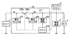
- FIG. 5 is a block diagram illustrating the configuration of the voltage measurement device 2C and the configuration around it.
- the same components as those described in the first embodiment are denoted by the same reference numerals, and the description thereof is omitted.
- the voltage measurement device 2C has a configuration in which a power storage device 206 and a step-up / down circuit 208 are added to the voltage measurement device 2A.
- the power storage device 206 is, for example, an electric double layer capacitor, and its capacitance is, for example, about several to several tens of F.
- the power storage devices 1 and 206 can be grasped as a first power storage device and a second power storage device, respectively.
- a bidirectional buck-boost circuit is adopted as the buck-boost circuit 208.
- the step-up / step-down circuit 208 is connected to the DC bus 211, and the storage device 206 is connected to the DC bus 211 via the step-up / step-down circuit 208.
- the conversion of the voltage between power storage device 206 and DC bus 211 is performed by step-up / step-down circuit 208.
- the step-up / step-down circuit 208 enables either charging from the DC bus 211 to the power storage device 206 or discharging from the power storage device 206 to the DC bus 211.
- the discharge can be employed for either the power supply from the storage device 206 to the vehicle load 3 or the power supply to the power supply circuit 203.
- the voltage measuring unit 202 measures the voltage Vb as in the first embodiment. Therefore, the voltage measuring device 2C can also execute the flowchart shown in FIG. 2 similarly to the voltage measuring device 2A, whereby the measurement of the open circuit voltage of the storage device 1 causes the shortage of electric power while the vehicle is traveling. Is avoided.
- the alternator 4 does not generate power, but it is necessary to supply power to the vehicle load 3.
- the current required for such power supply is called dark current, and is required for wireless communication such as the function of opening a door wirelessly.
- dark current is obtained by discharge of power storage device 1. Therefore, when the relay 200 is opened and the open circuit voltage is measured, this dark current is interrupted. Moreover, power is not supplied from the alternator 4 to the power supply circuit 203. Therefore, even if the relay 200 is opened to measure the open circuit voltage when the vehicle is stopped, the control circuit 204 does not operate.
- the open circuit voltage of the storage device 1 is measured without blocking the dark current even when the vehicle is stopped.
- the engine ECU 5 shown in FIG. 1 for instructing the generated voltage to the alternator 4 is omitted.
- FIG. 6 is a flowchart illustrating the operation of the voltage measurement device 2C according to the second embodiment, and shows control by the control circuit 204.
- Steps S301, S303, S304, S305, S307, and S308 are the same steps as steps S101, S103, S104, S105, S107, and S108 of FIG. 2, respectively.
- steps S302a and S302b are executed in place of step S102 of the first embodiment.
- control circuit 204 determines whether or not voltage Vc of power storage device 206 serving as the auxiliary power is normal. Similar to step S102, if the determination result is negative, step S308 is executed, and the control circuit 204 turns on (closes) the relay 200. Then, in step S309, power storage device 206 is charged from power storage device 1 via relay 200 and DC bus 211. On the other hand, if the determination result is affirmative, step S302 b is executed.
- control circuit 204 detects voltage Vc via step-up / step-down circuit 208.
- the voltage Vc is equal to or higher than the third threshold, the voltage of the auxiliary power supply is normal.
- the voltage Vc is lower than the third threshold, it is determined that the voltage is not normal.
- the third threshold is a threshold for the voltage Vc which can convert the voltage Vb to a voltage sufficient to allow the step-up / step-down circuit 208 to supply the dark current to the vehicle load 3 sufficiently. Since the detection of the voltage Vc is a known technique, the detailed description is omitted here.
- step S302 b since it is determined in step S302 a that the dark current is secured even if the relay 200 is turned off, the power storage device 206 is discharged via the step-up / step-down circuit 208. Since the dark current can be secured by execution of step S302 b, step S303 is executed, and the control circuit 204 turns off (opens) the relay 200.
- step S306 is executed instead of step S106 of the first embodiment.
- step S306 the same determination as in step S302a is performed. If the determination result is negative, steps S308 and S309 are executed. If the determination result is affirmative, step S307 is executed, and step S305 or steps S308 and S309 are executed as in step S107.
- control circuit 204 opens / closes between the ends 200 a and 200 b depending on whether the voltage Vc of the power storage device 206 is equal to or higher than the third threshold.
- the open circuit voltage can be measured even while the vehicle is stopped, and the dark current is secured. Ru.
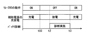
- FIG. 7 is a graph in which the horizontal axis represents time, and shows the operation of the relay 200, charging / discharging of the power storage device 206 (denoted as "auxiliary power supply” in the figure), and the state of battery diagnosis.
- step S302a At time t03, an affirmative determination is made in step S302a, steps S302b and S303 are executed, and the relay 200 is turned off (opened). Thereafter, steps S304, S302a, S302b, and S303 are repeatedly executed, and step S305 is executed at time t2. Thus, after step S303 is performed, the case where negative determination is not made by step S302a until step S305 is performed is illustrated.
- step S306 a negative determination is not made in step S306 until a positive determination is obtained in step S307.
- a positive determination is obtained in step S307, and the relay 200 is turned on (closed) by executing step S308.
- step S306 the battery determination is interrupted, the relay 200 is turned on (closed) by executing step S308, and the power storage device 206 is charged in step S309.
- power storage device 206 as an auxiliary power supply as described above, power is supplied to power supply circuit 203 even while the vehicle is parked, operation failure of control circuit 204 is avoided, and the open circuit voltage of power storage device 1 is measured. . Moreover, the dark current can be secured by adopting the determinations of steps S302a and S306a.
- the relay 200 be a normally closed type. Even in the case of the normally closed type, the above operation is not disturbed, and even if the power supply from the storage device 206 is insufficient to cause the control circuit 204 to malfunction, the storage device 1 is not connected via the closed relay 200. This is because the power supply circuit 203 is supplied with power, and the operation of the control circuit 204 is restored.
- step S106 whether the current flowing to the vehicle load 3 has increased may be adopted as the basis of the determination of step S106.
- the increase of the current causes a shortage of power supply to the vehicle load 3 when the relay 200 is open.
- step S108 is executed, and if the current does not increase, step S107 is executed.
- the ability of the step-up / step-down circuit 208 to convert the voltage Vc into the voltage Vb is preset.
- the first threshold may be set to K times the third threshold, and step S102 may be used instead for either of steps S302a and S306. That is, also in the second embodiment, by setting the first threshold as described above, the control circuit 204 closes the voltage between the ends 200a and 200b when the voltage Vb is lower than the first threshold. It is possible to close between the ends 200a and 200b when Vc is less than or equal to the third threshold.
- power storage device 206 may be incorporated in voltage measurement device 2C as illustrated in FIG. 5 or may be provided outside voltage measurement device 2C.
- the power storage device 206 and the voltage measurement device 2C are collectively a voltage measurement system that measures the open-circuit voltage of the power storage device 1.
- Voltage measuring devices 2A and 2C may be built in a relay box mounted on a vehicle, or may be provided between power storage device 1 and the relay box.
- each structure demonstrated by said each embodiment and each modification can be combined suitably, as long as there is no contradiction mutually.
- Power storage device (first power storage device) 2A voltage measuring device 2C voltage measuring device 3 vehicle load 4 alternator 200 relay 200a end (second end) 200b end (first end) 201 Voltage measurement unit (second voltage measurement unit) 202 Voltage Measurement Unit (First Voltage Measurement Unit) 203 power supply circuit 204 control circuit 206 power storage device (second power storage device) 208 Buck-Boost Circuit 211 DC Bus
Landscapes
- Engineering & Computer Science (AREA)
- Power Engineering (AREA)
- Mechanical Engineering (AREA)
- General Chemical & Material Sciences (AREA)
- Chemical Kinetics & Catalysis (AREA)
- Electrochemistry (AREA)
- Chemical & Material Sciences (AREA)
- Manufacturing & Machinery (AREA)
- Physics & Mathematics (AREA)
- General Physics & Mathematics (AREA)
- Charge And Discharge Circuits For Batteries Or The Like (AREA)
- Secondary Cells (AREA)
- Measurement Of Current Or Voltage (AREA)
- Tests Of Electric Status Of Batteries (AREA)
Priority Applications (2)
| Application Number | Priority Date | Filing Date | Title |
|---|---|---|---|
| US15/773,401 US10677851B2 (en) | 2015-11-30 | 2016-11-25 | Voltage measurement device, voltage measurement system |
| CN201680066058.3A CN108352716B (zh) | 2015-11-30 | 2016-11-25 | 电压测定装置、电压测定系统 |
Applications Claiming Priority (2)
| Application Number | Priority Date | Filing Date | Title |
|---|---|---|---|
| JP2015233025A JP6418141B2 (ja) | 2015-11-30 | 2015-11-30 | 電圧測定装置、電圧測定システム |
| JP2015-233025 | 2015-11-30 |
Publications (1)
| Publication Number | Publication Date |
|---|---|
| WO2017094620A1 true WO2017094620A1 (ja) | 2017-06-08 |
Family
ID=58797298
Family Applications (1)
| Application Number | Title | Priority Date | Filing Date |
|---|---|---|---|
| PCT/JP2016/085014 Ceased WO2017094620A1 (ja) | 2015-11-30 | 2016-11-25 | 電圧測定装置、電圧測定システム |
Country Status (4)
| Country | Link |
|---|---|
| US (1) | US10677851B2 (https=) |
| JP (1) | JP6418141B2 (https=) |
| CN (1) | CN108352716B (https=) |
| WO (1) | WO2017094620A1 (https=) |
Families Citing this family (5)
| Publication number | Priority date | Publication date | Assignee | Title |
|---|---|---|---|---|
| JP6520665B2 (ja) * | 2015-11-30 | 2019-05-29 | 株式会社オートネットワーク技術研究所 | 電圧測定装置、電圧測定システム |
| JP6750288B2 (ja) * | 2016-04-15 | 2020-09-02 | 株式会社オートネットワーク技術研究所 | リレー装置 |
| US10549649B2 (en) * | 2017-11-10 | 2020-02-04 | GM Global Technology Operations LLC | Maximum current calculation and power prediction for a battery pack |
| JP6819719B2 (ja) * | 2019-04-24 | 2021-01-27 | スズキ株式会社 | 車両用電源装置 |
| KR102851396B1 (ko) | 2019-10-10 | 2025-08-26 | 주식회사 엘지에너지솔루션 | 히팅 패드 제어 장치 |
Citations (4)
| Publication number | Priority date | Publication date | Assignee | Title |
|---|---|---|---|---|
| JP2003291754A (ja) * | 2002-04-01 | 2003-10-15 | Toyota Motor Corp | 車両用電源装置 |
| JP2011230685A (ja) * | 2010-04-28 | 2011-11-17 | Denso Corp | 車両用電子制御装置 |
| JP2013051823A (ja) * | 2011-08-31 | 2013-03-14 | Toyota Industries Corp | 電池状態監視システムおよび方法 |
| JP2015020619A (ja) * | 2013-07-19 | 2015-02-02 | 株式会社オートネットワーク技術研究所 | 車両用給電装置 |
Family Cites Families (11)
| Publication number | Priority date | Publication date | Assignee | Title |
|---|---|---|---|---|
| US4733100A (en) * | 1987-01-14 | 1988-03-22 | Fox Technology, Inc. | Automatic on/off circuit with time delay |
| JP2812066B2 (ja) * | 1992-06-04 | 1998-10-15 | 三菱電機株式会社 | 車両用電源電圧切換え装置 |
| JP5094797B2 (ja) * | 2009-08-07 | 2012-12-12 | 日立オートモティブシステムズ株式会社 | 直流電源平滑用コンデンサーの放電回路 |
| US9190860B2 (en) * | 2011-11-15 | 2015-11-17 | Maxwell Technologies, Inc. | System and methods for managing a degraded state of a capacitor system |
| JP5477409B2 (ja) * | 2012-03-12 | 2014-04-23 | 株式会社デンソー | 電源システム |
| JP5966583B2 (ja) * | 2012-05-11 | 2016-08-10 | 日産自動車株式会社 | 電力制御装置 |
| JP5961854B2 (ja) * | 2012-07-23 | 2016-08-02 | 株式会社明電舎 | モータ駆動回路 |
| JP5983171B2 (ja) * | 2012-08-10 | 2016-08-31 | 株式会社Gsユアサ | スイッチ故障診断装置、蓄電装置 |
| JP5772781B2 (ja) * | 2012-10-10 | 2015-09-02 | トヨタ自動車株式会社 | 車両、電源システムおよび電源システムの制御方法 |
| US20160016483A1 (en) * | 2013-04-03 | 2016-01-21 | Autonetworks Technologies, Ltd. | Control apparatus, power supply control apparatus, charge control method, charge control apparatus, and power supply apparatus for vehicles |
| US9970988B2 (en) * | 2015-11-20 | 2018-05-15 | Tabuchi Electric Co., Ltd. | Relay abnormality detection device and power conditioner |
-
2015
- 2015-11-30 JP JP2015233025A patent/JP6418141B2/ja not_active Expired - Fee Related
-
2016
- 2016-11-25 US US15/773,401 patent/US10677851B2/en not_active Expired - Fee Related
- 2016-11-25 WO PCT/JP2016/085014 patent/WO2017094620A1/ja not_active Ceased
- 2016-11-25 CN CN201680066058.3A patent/CN108352716B/zh not_active Expired - Fee Related
Patent Citations (4)
| Publication number | Priority date | Publication date | Assignee | Title |
|---|---|---|---|---|
| JP2003291754A (ja) * | 2002-04-01 | 2003-10-15 | Toyota Motor Corp | 車両用電源装置 |
| JP2011230685A (ja) * | 2010-04-28 | 2011-11-17 | Denso Corp | 車両用電子制御装置 |
| JP2013051823A (ja) * | 2011-08-31 | 2013-03-14 | Toyota Industries Corp | 電池状態監視システムおよび方法 |
| JP2015020619A (ja) * | 2013-07-19 | 2015-02-02 | 株式会社オートネットワーク技術研究所 | 車両用給電装置 |
Also Published As
| Publication number | Publication date |
|---|---|
| US20180328993A1 (en) | 2018-11-15 |
| CN108352716B (zh) | 2021-07-16 |
| CN108352716A (zh) | 2018-07-31 |
| US10677851B2 (en) | 2020-06-09 |
| JP2017103845A (ja) | 2017-06-08 |
| JP6418141B2 (ja) | 2018-11-07 |
Similar Documents
| Publication | Publication Date | Title |
|---|---|---|
| JP6546617B2 (ja) | 電力分配システム | |
| JP6527906B2 (ja) | 電力分配システム | |
| CN108011433B (zh) | 蓄电装置及其控制方法、蓄电装置监测用系统、存储介质 | |
| WO2017094620A1 (ja) | 電圧測定装置、電圧測定システム | |
| US11404899B2 (en) | Battery system and battery management device for cancelling polarization voltage by applying a reverse current | |
| US10916962B2 (en) | Dual energy store and dual charging source vehicle power supply system and vehicle drive system | |
| JP2019146305A (ja) | 電源システム | |
| CN104737412B (zh) | 电源管理系统及电源管理方法 | |
| JP6099824B2 (ja) | 車載電源網および車載電源網を動作させる方法 | |
| JP2009259762A (ja) | 複数のリレーを有する電源装置 | |
| US20170292990A1 (en) | Power supply apparatus, transport device including power supply apparatus, determination method of determining state of sensor detecting current value, and computer readable medium for determining state | |
| US20190305587A1 (en) | Vehicle backup device | |
| US20180326925A1 (en) | Charge/discharge device | |
| JP7101506B2 (ja) | 電池劣化判定装置 | |
| WO2017068874A1 (ja) | 車載用電源装置 | |
| JP6520665B2 (ja) | 電圧測定装置、電圧測定システム | |
| JP6220158B2 (ja) | リレー診断装置 | |
| US20130241564A1 (en) | Method for Determining a Charge State of a Battery | |
| WO2022210441A1 (ja) | 予備電源装置及び予備電源装置の制御方法 | |
| JP6409635B2 (ja) | 蓄電システム | |
| JP5411046B2 (ja) | 車両用電池管理装置及び電流センサのオフセット検出方法 | |
| JP7769596B2 (ja) | 車両電源システム | |
| CN104081620B (zh) | 管理机动车辆的电气结构的电能的方法及实现该方法的机动车辆 | |
| JP2015209126A (ja) | 電源装置及びその制御方法 | |
| JP2026058837A (ja) | 車両用電源装置 |
Legal Events
| Date | Code | Title | Description |
|---|---|---|---|
| 121 | Ep: the epo has been informed by wipo that ep was designated in this application |
Ref document number: 16870557 Country of ref document: EP Kind code of ref document: A1 |
|
| WWE | Wipo information: entry into national phase |
Ref document number: 15773401 Country of ref document: US |
|
| NENP | Non-entry into the national phase |
Ref country code: DE |
|
| 122 | Ep: pct application non-entry in european phase |
Ref document number: 16870557 Country of ref document: EP Kind code of ref document: A1 |